mission information and test systems summary of ...€¦ · mission information and test systems ....
TRANSCRIPT

NASA/TM—2013–216043
Mission Information and Test Systems Summary of Accomplishments, 2011 Sean E. McMorrow and Roberta B. Sherrard Dryden Flight Research Center, Edwards, California
February 2013

NASA STI Program ... in Profile
Since its founding, NASA has been dedicated to the advancement of aeronautics and space science. The NASA scientific and technical information (STI) program plays a key part in helping NASA maintain this important role.
The NASA STI program operates under the auspices of the Agency Chief Information Officer. It collects, organizes, provides for archiving, and disseminates NASA’s STI. The NASA STI program provides access to the NASA Aeronautics and Space Database and its public interface, the NASA Technical Reports Server, thus providing one of the largest collections of aeronautical and space science STI in the world. Results are published in both non-NASA channels and by NASA in the NASA STI Report Series, which includes the following report types:
• TECHNICAL PUBLICATION. Reports of
completed research or a major significant phase of research that present the results of NASA Programs and include extensive data or theoretical analysis. Includes compila- tions of significant scientific and technical data and information deemed to be of continuing reference value. NASA counter-part of peer-reviewed formal professional papers but has less stringent limitations on manuscript length and extent of graphic presentations.
• TECHNICAL MEMORANDUM. Scientific and technical findings that are preliminary or of specialized interest, e.g., quick release reports, working papers, and bibliographies that contain minimal annotation. Does not contain extensive analysis.
• CONTRACTOR REPORT. Scientific and technical findings by NASA-sponsored contractors and grantees.
• CONFERENCE PUBLICATION. Collected papers from scientific and technical conferences, symposia, seminars, or other meetings sponsored or co-sponsored by NASA.
• SPECIAL PUBLICATION. Scientific, technical, or historical information from NASA programs, projects, and missions, often concerned with subjects having substantial public interest.
• TECHNICAL TRANSLATION. English-language translations of foreign scientific and technical material pertinent to NASA’s mission.
Specialized services also include organizing and publishing research results, distributing specialized research announcements and feeds, providing information desk and personal search support, and enabling data exchange services.
For more information about the NASA STI program, see the following:
• Access the NASA STI program home page at
http://www.sti.nasa.gov
• E-mail your question to [email protected]
• Fax your question to the NASA STI Information Desk at 443-757-5803
• Phone the NASA STI Information Desk at 443-757-5802
• Write to: STI Information Desk NASA Center for AeroSpace Information 7115 Standard Drive Hanover, MD 21076-1320
This page is required and contains approved text that cannot be changed.

NASA/TM—2013–216043
Mission Information and Test Systems Summary of Accomplishments, 2011 Sean E. McMorrow and Roberta B. Sherrard Dryden Flight Research Center, Edwards, California
Insert conference information, if applicable; otherwise delete
Click here: Press F1 key (Windows) or Help key (Mac) for help
National Aeronautics and Space Administration Dryden Flight Research Center Edwards, CA 93523-0273
February 2013

Enter acknowledgments here, if applicable.
Click here: Press F1 key (Windows) or Help key (Mac) for help
Available from:
Click here: Press F1 key (Windows) or Help key (Mac) for help
NASA Center for AeroSpace Information 7115 Standard Drive
Hanover, MD 21076-1320 443-757-5802

v
Preface The Mission Information and Test Systems Directorate (Code M) annual report for 2011 showcases the highlights and accomplishments of the Directorate by Branch in support of the following vision and mission statements.
• Code M Vision: To enable and showcase discoveries through flight. • Code M Mission: Enabling the advancement of Aeronautics, Science, Technology, and
Exploration through flight by evolving efficient and effective mission, information, and test systems.
Facilities and Assets The Research Aircraft Integration Facility (RAIF) provides the ability to seamlessly integrate simulation, and vehicle software and hardware systems under a single roof. This one-of-a-kind facility can simultaneously support a wide variety of advanced, highly integrated aerospace vehicles through all phases of a research program from conceptual design to flight. The RAIF offers high fidelity 6-degrees of freedom (DOF) batch and in-real-time flight simulation capabilities, as well as support for system integration and closed-loop verification and validation testing of vehicle components and flight vehicles. Also available are complete aircraft ground-support services including all electrical, hydraulic and cooling-air systems required for vehicle-system integration, functional checks, and routine aircraft maintenance. Western Aeronautical Test Range (WATR) is located at the Dryden Flight Research Center, part of the Edwards Air Force Base complex. The mission of the WATR is to support flight research operations and low earth-orbiting missions. WATR supplies a comprehensive set of resources for the control and monitoring of flight activities, real-time acquisition and reduction of research data, and effective communication of information to flight and ground crews. Precision radar provides tracking and space positioning information on research vehicles and other targets, including satellites. Fixed and mobile telemetry antennas receive real-time data and video signals from the research vehicle and relay this data to telemetry processing areas. The processed data is displayed at the engineering stations in the mission control center and archived in a post-flight storage area. The Flight Loads Laboratory (FLL) was constructed at the National Aeronautics and Space Administration (NASA) Dryden Flight Research Center in 1964 as a unique national laboratory to support flight research and tests of aircraft structures. The FLL conducts mechanical-load and thermal studies of structural components and complete flight vehicles in addition to performing calibration tests of vehicle instrumentation for real-time determination flight loads. Mechanical loads and thermal conditions can be applied either separately or simultaneously to represent combined thermal-mechanical load conditions. The FLL can be used to test aerospace structures from subsonic through hypersonic flight regimes. The Consolidated Information Technology Center is Dryden’s new 22,000-square-foot facility is a state-of-art facility that consolidates all information technology (IT) services to enable reliable, secure, and rapid analysis of critical flight research data. The facility provides data processing, distribution, display, and storage.
Code M Branches Code MC—The NASA Dryden Flight Research Center Western Aeronautical Test Range’s (WATR) Range Engineering Branch provides flight-test range development services and maintains two mission

vi
control centers. The major services that the Range Engineering Branch performs are range systems engineering, test information engineering, and data processing and display system/software development. Code ME—The Simulation Engineering Branch develops high-fidelity engineering simulations that can support various research phases ranging from conceptual studies through flight testing as well as providing a research tool that enhances the quality, quantity, and feasibility of the research objectives. Code MI—The Information Services Branch provides integrated, secure, and efficient information technology solutions and services that enable NASA Dryden’s mission. Code MR—The NASA DFRC WATR’s Range Operations Branch is responsible for operating, maintaining, and building the WATR systems required to support safe flight test and research activities. Code MT—The Technical Laboratory Services Branch supports Structures Engineering in the Flight Loads Laboratory and Simulation Engineering in the Research Aircraft Integration Facility. The core group consists of Electronic Technicians and Engineering Technicians (Mechanical), who perform the operations, maintenance, buildup, instrumentation, testing, troubleshooting, and data collection of test articles, flight hardware, flight simulators, and the laboratory test equipment.
vii
Table of Contents Range Engineering ........................................................................................................................ 1 Positional Awareness Map3D ................................................................................................. 2 Chapter 10 Tools ..................................................................................................................... 4 WINGS Dual RSO Station...................................................................................................... 6 Global Hawk KQ-X ................................................................................................................ 7 Ikhana Build-up and Test, Part of ADS-B .............................................................................. 8 Phantom Eye and Phantom Ray Supported Installation, Integration, and Testing of Unique Data Links ...................................................................... 9 Enhanced Flight Termination System ....................................................................................10 Simulation Engineering ...............................................................................................................11 Automatic Ground Collision Avoidance System – An Android OS Implementation ...........12 SOFIA Hardware-In-the-Loop Simulation Laboratory .........................................................13 F-18 Test Bench .....................................................................................................................15 PCI MultiFunction I/O Card Driver .......................................................................................17 F-18 PCM Simulator ..............................................................................................................18 Small UAV Automatic Ground Collision Avoidance System User Interface .......................20 Digital Strip Chart ..................................................................................................................22 Heads Down Display System.................................................................................................24 NESC Model Exchange .........................................................................................................26 Information Services ....................................................................................................................29 Data Center Transition ...........................................................................................................30 Agency CBI Integration .........................................................................................................32 DFRC Emergency Operations Center ....................................................................................34 I3P NICS Transition ..............................................................................................................35 DFRC/DAOF Code MI Short-Term External Partner Support .............................................36 DFRC Simulation Lab Network Infrastructure Upgrade and Modernization .......................38 DAOF Code MI Large Conference Room .............................................................................39 Ikhana GCS Accreditation and Authorization .......................................................................41 Online Dryden Information Exchange ...................................................................................42 Remote Desktop Services ......................................................................................................43 SOFIA Compilation ...............................................................................................................44 Aircraft Work Order System ..................................................................................................45 Range Operations .........................................................................................................................47 Western Aeronautical Test Range (WATR) Operational Test ..............................................48 WATR Data Path Acquisition to Test Engineer ....................................................................49 Telemetry Systems .................................................................................................................50 Time Space Position Information Systems ............................................................................52 Video Systems .......................................................................................................................54 RF Communications Systems ................................................................................................56 Ground Voice Communications Systems ..............................................................................58 Data Distribution Systems .....................................................................................................59 WATR Mobile Operation Facility Systems ...........................................................................60 Real-Time Data Processing/Monitoring Systems ..................................................................62 Range Safety Ground Systems...............................................................................................64 Technical Laboratory Services ....................................................................................................67

viii
Structurally Integrated Thermal Protection System ...............................................................68 Phantom Eye Ground Vibration Test/Structural Moment of Inertia .....................................70 G-III Aircraft ..........................................................................................................................71 Photogrammetry System to Temecula Temporary Duty .......................................................72 Stratospheric Observatory for Infrared Astronomy ...............................................................73 Dynamic Inertia Measurement Test .......................................................................................74 X-48 Mass Properties Testing ................................................................................................75 HyperSonic Vehicle Test Article ...........................................................................................76 F-18 Test Bench .....................................................................................................................77 Simulation Electric Stick and Cockpit Interface Unit............................................................79 Mobile Cockpit Build ............................................................................................................81 Blended Wing Body (X-48B) Aircraft ..................................................................................83 Consolidated Information Technology Center (CITC) ................................................................85 Flight Loads Laboratory ..............................................................................................................87 Research Aircraft Integration Facility (RAIF) .............................................................................89 Western Aeronautical Test Range (WATR) ................................................................................91 2011 Awards, Recognition, and Conference Papers ....................................................................95

1
Range Engineering
Code MC is the Range Engineering Branch of the Western Aeronautical Test Range (WATR), which is part of the National Aeronautics and Space Administration’s Dryden Flight Research Center (Edwards, California). Code MC provides flight-test range development services and maintains two mission control centers (fig. 1). The major services that the Range Engineering Branch performs are range systems engineering, test information engineering, and data processing and display system/software development.
Photo courtesy: NASA/Robert Guere
Figure 1. Mission Control Center 2.

2
Positional Awareness Map3D
Summary
Positional awareness in the Mission Control Center (MCC) is a crucial aspect associated with real-time mission support. During a flight, it is important for personnel in the MCC to know where the aircraft is, if the aircraft is entering a restricted area, whether or not the aircraft is following the expected flight path, et cetera. Advances in computing and high resolution imaging have provided the tools to create more robust and precise mapping applications. These advances in hardware and software have generated a need for improvements in the MCC positional awareness capability, resulting in the development of the Positional Awareness Map3D (PAM3D) application.
The primary objective of the PAM3D software development is to replace the current outdated 2-dimensional (2D) positional awareness mapping application (fig. 1) in the MCC of the National Aeronautics and Space Administration (NASA) Dryden Flight Research Center (Edwards, California). This application must provide the functionality of the original system, while adding improvements such as high resolution imagery and a 3-dimensional (3D) display capability (fig. 2).
Before development, a study was conducted on various commercial off-the-shelf (COTS) mapping products to determine if COTS software could be utilized to minimize development time for specialized requirements. Once the study of COTS products was completed, the decision was made to purchase Analytical Graphics Incorporation’s (AGI) (Exton, Pennsylvania) Satellite Tool Kit (STK) because of its 2D and 3D capabilities, accurate positional information, terrain mapping, and ability to develop customized configuration files. An agile software development approach was applied to the PAM3D development, following NASA and Dryden software development processes.
Figure 1. Current 2D mapping application, GRIM.

3
Figure 2. PAM3D 2D and 3D windows.
Contacts
Darryl Burkes, DFRC, Code M, (661) 276-2517 Matt Cheung, DFRC, Code MC, (661) 276-5226

4
Chapter 10 Tools
Summary
The Western Aeronautical Test Range (WATR) of the National Aeronautics and Space Administration (NASA) Dryden Flight Research Center (DFRC) (Edwards, California) concurrently supports flight testing and research for multiple projects. Projects commonly record data on board the research vehicle on a Chapter 10 compliant data recorder. Chapter 10 is a digital recording standard and is part of the Inter-Range Instrumentation Group (IRIG) 106 standards. As part of the Dryden flight research environment, real-time data is converted after a flight to a Dryden standard format (CMP4). CMP4 is a compressed file format that contains descriptive information about its contents. For Chapter 10 files this conversion requires the use of commercially available software to read the Chapter 10 files and in-house developed software to convert the output from the Chapter 10 reader software to the CMP4 file format. These CMP4 files are then transferred to a central storage system and made available across the Dryden campus to flight researchers.
Different vendors of Chapter 10 recorders produce files with minor variances and errors. The most common error found within vendor files are time errors. It appears that most recorders have difficulty writing the data to the file within one second. Since the use of Chapter 10 recorders across the center is growing, the WATR determined that there was a need to generate a tool that would take any of the Chapter 10 files received from any project and convert them into a Chapter 10 file that the WATR software reader could accept.
The objective of Chapter 10 Tools is to identify and correct the following: Chapter 10 file-structure errors, Telemetry Attributes Transfer Standard (TMATS) errors, time errors, packet errors, and data type errors. Although the focus of the WATR was to generate a Chapter 10 file that the WATR’s reader would accept, the solution should also be able to produce a file that any Chapter 10 file reader would accept.
The WATR started architecting a solution by gathering requirements and laying out some basic ground rules. It was decided that the most effective approach would be to use a modular software design with a plug-in architecture. The plug-in architecture was used for the part of the application referred to as the data type modules. The data type modules are modules that detect and correct errors in data packets. The data types supported by Chapter 10 include pulse code modulation (PCM), 1553, ARINC-429, time, video, Ethernet, analog, discrete, computer generated, message, image, UART, IEEE 1394, and parallel. For the first release the computer generated and time data type capabilities were implemented.
The application is segmented into five primary functional areas; the Chapter 10 reader, the TMATS module, the controller, the channel pipelines, and the Chapter 10 writer. See figure 1 for an illustration of the functional areas and their relationships.
The Chapter 10 Reader: • Reads data from the original Chapter 10 file. • Detects and corrects errors in the Chapter 10 headers and trailers. • Strips the data type body from the packets and passes them to the channel pipelines.
The TMATS Module: • Detects and corrects errors in the TMATS section. • Provides users the ability to manually correct errors. • Provides the corrected TMATS information to the controller.

5
The Controller: • Receives setup information from the user (channels to be process, start times, end times, type of
error correction to be performed, et cetera). • Configures the channel pipelines. • Passes information necessary for the correct processing of the data to the data type modules.
The Channel Pipelines: • Each data type has its own pipeline. • Each pipeline has a packet reader/writer and blocking queues to control the flow of data. • The data type processing module detects and corrects errors for that data type. The modules are
often referred to as filters because errors are removed from the file.
The Chapter 10 Writer:
• The Chapter 10 writer gathers the packet bodies from all of the channel pipelines and assembles them into a valid Chapter 10 packet before writing them out to the new Chapter 10 file.
Figure 1. Chapter 10 Tools data flows.
The application prototype and paper were presented at the International Telemetry Conference (ITC) in October 2011. Version 1.0 of the application is currently in the functional test cycle of verification and validation (V&V). The Chapter 10 Tools application is expected to be released in 2012.
Contacts
Darryl Burkes, DFRC, Code M, (661) 276-2517 Matt Cheung, DFRC, Code MC, (661) 276-5226
6
WINGS Dual RSO Station
Summary
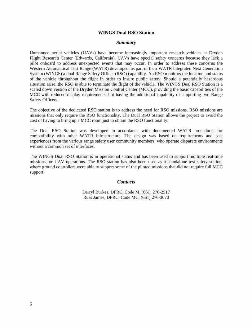
Unmanned aerial vehicles (UAVs) have become increasingly important research vehicles at Dryden Flight Research Center (Edwards, California). UAVs have special safety concerns because they lack a pilot onboard to address unexpected events that may occur. In order to address these concerns the Western Aeronautical Test Range (WATR) developed, as part of their WATR Integrated Next Generation System (WINGS) a dual Range Safety Officer (RSO) capability. An RSO monitors the location and status of the vehicle throughout the flight in order to insure public safety. Should a potentially hazardous situation arise, the RSO is able to terminate the flight of the vehicle. The WINGS Dual RSO Station is a scaled down version of the Dryden Mission Control Center (MCC), providing the basic capabilities of the MCC with reduced display requirements, but having the additional capability of supporting two Range Safety Officers.
The objective of the dedicated RSO station is to address the need for RSO missions. RSO missions are missions that only require the RSO functionality. The Dual RSO Station allows the project to avoid the cost of having to bring up a MCC room just to obtain the RSO functionality.
The Dual RSO Station was developed in accordance with documented WATR procedures for compatibility with other WATR infrastructure. The design was based on requirements and past experiences from the various range safety user community members, who operate disparate environments without a common set of interfaces.
The WINGS Dual RSO Station is in operational status and has been used to support multiple real-time missions for UAV operations. The RSO station has also been used as a standalone test safety station, where ground controllers were able to support some of the piloted missions that did not require full MCC support.
Contacts
Darryl Burkes, DFRC, Code M, (661) 276-2517 Russ James, DFRC, Code MC, (661) 276-3070

7
Global Hawk KQ-X
Summary
The Dryden Flight Research Center (Edwards, California) Global Hawk aircraft served as the platforms for the KQ-X project with Northrop Grumman (Falls Church, Virginia). These preliminary flights brought the project closer to demonstrating the first autonomous aerial refueling between two unmanned, high-altitude aircraft. Several demonstration flights were conducted before the close formation flight, which included tanker and receiver first flights, and a distant formation flight. The Code MC team ensured that all safety precautions and measures were taken when preparing for, and conducting all of the ground and flight demonstrations. Code MC performed extensive analysis, simulations, laboratory, and ground tests as well as multiple safety review boards for the project, as well as assisting with the ground and flight demonstration.
In 2011, the program was preparing to demonstrate autonomous fuel transfer between two Global Hawks, enabling flights of up to one-week endurance (fig. 1). This project was a follow-on to a 2006 autonomous aerial refueling demonstration (AARD) activity that used an F/A-18 Hornet (McDonnell Douglas now The Boeing Company, Chicago, Illinois) as a surrogate unmanned aircraft to autonomously refuel via a probe and drogue from a Boeing 707 tanker.
Photo courtesy: Northrop Grumman
Figure 1. Tandem Global Hawk refuel.
Contacts
Darryl Burkes, DFRC, Code M, (661) 276-2517 Matt Cheung, DFRC, Code MC, (661) 276-5226

8
Ikhana Build-up and Test, Part of ADS-B
Summary
Ikhana-supported build-up and testing as part of an automatic dependent surveillance–broadcast (ADS-B) integration sub-task under the Unmanned Aircraft Systems (UAS) in the National Airspace System (NAS) project. On the ground network side, the Western Aeronautical Test Range (WATR) Range Systems Engineers designed, tested, and integrated the interface equipment necessary to ingest ADS-B data from the Ikhana unmanned aerial vehicle (UAV) in real-time flights in the R-2508 airspace. This requirement was levied against Code MC due to the amount of knowledge of aircraft and ground systems capabilities and constraints.
Contacts
Darryl Burkes, DFRC, Code M, (661) 276-2517 Russ James, DFRC, Code MC, (661) 276-3070

9
Phantom Eye and Phantom Ray Supported Installation, Integration, and Testing of Unique Data Links
Summary
National Aeronautics and Space Administration (NASA) Dryden Flight Research Center (Edwards, California) was selected by The Boeing Company (Chicago, Illinois) to host its flight test operations for the Phantom Ray (fig. 1). While at Dryden, the aircraft underwent testing and preparations for its first flights as an advanced technology test bed. Dryden provided range operations support by the Mission Information and Test Systems team for the project.
Dryden also participated in The Boeing Company’s unmanned hydrogen-powered Phantom Eye (fig. 2) high-altitude, long-endurance demonstrator aircraft to prepare it for flight tests. Dryden hosted the Boeing flight test operation; and provided hangar facilities, engineering, ground test, and test range support for the project.
Photo courtesy: The Boeing Company
Figure 1. Boeing X-45C Phantom Ray.
Photo courtesy: The Boeing Company
Figure 2. Boeing Phantom Eye.
Contacts
Darryl Burkes, DFRC, Code M, (661) 276-2517 Matt Cheung, DFRC, Code MC, (661) 276-5226

10
Enhanced Flight Termination System
Summary
Flight termination systems (FTS) are installed and integrated on airborne vehicles to protect the public from the risks involved with launching and testing airborne vehicles on the United States National Test Ranges. The Enhanced Flight Termination System (EFTS) is required to prevent future mishaps on airborne vehicles employing flight termination systems by developing airborne and ground hardware to replace or upgrade current systems. EFTS has been led via the efforts of the alliance between the Air Force Test Center (AFTC) (Edwards, California) and National Aeronautics and Space Administration (NASA) Dryden Flight Research Center (DFRC) (Edwards, California) with considerable amounts of support from all the United States ranges, industry, and other entities involved with FTS. There exist two traditional FTSs, based upon analog radio technology. EFTS is a new system, using digital technology, which allows for a significant amount of authentication and encryption. With any FTS, there are chances that inadvertent terminations may occur. The significant amount of authentication and encryption that EFTS provides helps to minimize those risks. The goal of the EFTS program is to develop a more robust and secure command link to send commands to those vehicles. At NASA DFRC, the traditional FTS is aging. The EFTS equipment replaces the aging traditional FTS equipment. In addition, the EFTS upgrades from the traditional analog systems to the newer digital system, which allows for the authentication and encryption. At NASA DFRC, EFTS airborne and ground hardware has been developed and integrated with the FTS. In conjunction with the AFTC at Edwards AFB, the Western Aeronautical Test Range (WATR) of NASA DFRC is the first range in the world to consistently, operationally support EFTS. The EFTS has been operational at NASA DFRC since the first quarter of 2010. NASA DFRC has successfully supported over 100 EFTS missions, which included ground and flight tests. Four projects have successfully flown EFTS equipped missions: Global Observer, X-48/Blended Wing Body, Phantom Ray, and Phantom Eye. A fifth project, Dream Chaser, is currently being built up to utilize EFTS for flight test. For all the EFTS projects combined, there have been over thirty EFTS flights. NASA DFRC has also developed an EFTS flight termination receiver (FTR) recertification procedure and test set, which follows the Range Commanders Council EFTS testing standard. Recertification of EFTS FTRs is needed to ensure that the EFTS FTRs continue to meet operational standards, which ensures the full functionality of the EFTS FTRs. This test set has allowed NASA DFRC to continually recertify EFTS FTRs every six months, as required by the testing standard. Being at the forefront of the EFTS community, NASA DFRC is working with many government agencies to assist in EFTS range integration across the United States. The development, integration, and testing efforts done at NASA DFRC have been presented to the EFTS community. All results from the development, integration, and testing at NASA DFRC have also been shared with the EFTS community. The lessons learned at NASA DFRC have been conveyed to the EFTS community to help advance the technology and ease the integration and utilization of the technology within the EFTS community. As a result, all ranges in the United States have utilized the knowledge from NASA DFRC, have been able to reduce integration costs and growing pains, and are utilizing common technology.
Contacts Darryl Burkes, DFRC, Code M, (661) 276-2517 Matt Cheung, DFRC, Code MC, (661) 276-5226

11
Simulation Engineering
The Simulation Engineering Branch, Code ME, is known for developing high-fidelity engineering simulations (fig. 1) that can support various research phases ranging from conceptual studies through flight-testing as well as providing a research tool that enhances the quality, quantity, and feasibility of research objectives. This branch provides an engineering service that is positively recognized by its customers for its responsiveness, quality, and productivity.
EC04-0288-2
Figure 1. F-18 simulator, housed in the Research Aircraft Integration Facility.

12
Automatic Ground Collision Avoidance System – An Android OS Implementation
Summary
One of the Small Unmanned Aerial Vehicle (SUAV) Automatic Ground Collision Avoidance System (AGCAS) project goals was to demonstrate ground collision avoidance algorithms developed at the National Aeronautics and Space Administration Dryden Flight Research Center (Edwards, California) on a small consumer computing device. The device chosen was an Android smart phone. Initial algorithm development was done with Excel spreadsheets. The AGCAS logic was then derived from these spreadsheets and implemented in the Android Application Programming Interface (API).
Overview of the application functions: 1. Monitor external aircraft state data. 2. Handle user mode requests and mode selection logic. 3. Perform the algorithm calculations based on state data from the sensors. 4. Do error detection and reporting. 5. Log the algorithm outputs to local secure digital (SD) memory. 6. Send health, status, and algorithm state messages back over the USB to the user interface
computer in a timely fashion. 7. Monitor ground track information and relate it to a terrain database when determining collision
likelihood.
In a deployment, this application communicates with a user interface computer, which in turn links to an aircraft autopilot. When the algorithm determines a collision is imminent based on a predicted flight path, a request is sent from the Android device to the user interface computer. The interface computer will then assert a fly-up maneuver to the aircraft autopilot system.
The algorithm and phone application was tested on several flights and performed as predicted by the spreadsheet algorithm it was based on. Development of the algorithm is on-going, and phase two of the project intends to fly the phone on board the aircraft in a standalone collision avoidance system. For more information see:
http://www.nasa.gov/multimedia/videogallery/index.html?collection_id=14319&media_id=118854961 (accessed February 11, 2013).
Contacts
Benjamin J. Pearson, DFRC, Code ME, (661) 276-3779

13
SOFIA Hardware–In-the-Loop Simulation Laboratory
Summary
The Stratospheric Observatory for Infrared Astronomy (SOFIA) Hardware-In-the-Loop Simulation (HILS) lab provides a development as well as a verification and validation (V&V) facility for the SOFIA Mission Control and Communication System (MCCS). In the HILS, the simulation creates a flight environment for the MCCS to operate in. Various aircraft states and locations can be simulated, providing an environment in which MCCS hardware and software can be developed, integrated, and tested before being flown.
The simulation is based on the core simulation framework of the Dryden Flight Research Center (Edwards, California) and includes the aircraft 747SP model as well as various SOFIA subsystem models such as the Telescope Assembly (TA) and the Cavity Door Drive System (CDDS). Shown in the figure 1, the simulation communicates with the MCCS hardware over several connections including Ethernet, 1553 bus, and RS-422.
Figure 1. HILS lab block diagram.
The HILS lab is separated into two separate systems; a V&V system, and a development system. These two systems are functionally equivalent HIL simulators of the MCCS. The V&V system is kept under strict configuration control and is used for validation and verification of flight hardware and software before being put onto the aircraft. Much of the hardware in the V&V lab is flight spare, or equal to hardware which is on the SOFIA aircraft. The development system is under a more flexible configuration and is used for software and hardware development. Many of the hardware systems in the development system are lower cost, but functionally equivalent lab units of hardware systems on the aircraft.
The new facility, shown in figure 2, includes many new capabilities for SOFIA system development and testing. These capabilities include GPS signal for time servers and IRIG generation, and 400Hz aircraft power for testing power systems. Network connections to the Science Instrument lab and the hangar floor

14
provide the ability to connect the simulation with Science Instruments or to hardware on the SOFIA aircraft for testing and verification. For 2012, the HILS lab and simulation is being upgraded to support the SOFIA platform segment 3 upgrade. This upgrade includes adding new MCCS subsystems and data busses. In addition to the segment 3 changes, a TA HILS is being developed which will support hardware in the loop simulation of the TA Servo control Unit (TASCU), which controls the aiming and control of the telescope.
Figure 2. SOFIA Hardware-In-the-Loop Simulation Lab.
Contacts
Michael A. Hill, DFRC, Code ME, (661) 276-3779

15
F-18 Test Bench
Summary
Since the 1980’s, the Dryden Flight Research Center (Edwards, California) has used an F-18 test bench to verify and validate a wide range of flight hardware and software prior to being installed on flight research aircraft. However, the existing test bench is becoming increasingly difficult to maintain because of its age. Therefore, an effort was undertaken to build a new test bench (fig. 1) to replace the old one and at the same time increase the functionality of the test bench. Codes ME, RF, and RC have been instrumental at getting the new bench to its current state.
The objective of the test bench development for 2011 was to get the new test bench finished and operational. The test bench development team finished the hardware, software, and documentation aspects of the project. During 2011 the following development efforts were completed:
1. Integration of the test bench with the simulation 2. Hinge moment and sensor model updates 3. Ability to pass initiated built in test (IBIT) in both standalone and Hardware In the Loop
Simulation (HILS) configurations 4. Interface with the display computer (DC) user interface 5. Auto-calibration of Hardware Interface Unit (HIU) channels 6. Actuator model assembly (AMA) updates 7. Added support for an “Airborne Research Test System (ARTS) Input/Output (I/O) only”
configuration 8. Documentation updates to “as built” design
Photo courtesy: NASA/John Spooner
Figure 1. New F-18 test bench.
16
The new test bench now supports full HILS operation and can execute IBIT without any resulting bit logic inspection (BLIN) codes. Module level testing and integration testing has been conducted on the Signal Generator Computer (SGC), HIU, and AMA systems. The auto-calibration of the HIU channels is operational and saves days of effort to manually calibrate all of the channels each time that the flight hardware is changed.
The most recent change to the new test bench was a modification to support analog and discrete I/O to the ARTS computers. This change was made to enable the testing of the ARTS units that have been modified with analog and discrete I/O.
The new test bench is functionally complete. However, acceptance testing by Codes RF and RC still needs to be finished. Code ME will provide support for these tests as needed. This testing will consist of comparison testing of time history and frequency check cases between the new and old benches. Once this testing is complete, the F-18 project will move its flight control computer (FCC) testing to the new test bench.
Contacts
Gary Kellogg, DFRC, Code ME, (661) 276-3779

17
PCI MultiFunction I/O Card Driver
Summary
A Solaris driver has been developed to interface the G-III simulation to a commercial-off-the-shelf (COTS) Peripheral Component Interconnect (PCI) bus multifunction input/output (I/O) card.
The objective of this project was to provide analog I/O to the G-III simulation. Normally this would be done with the Cockpit Interface Unit (CIU). The CIU is a large standalone system that provides access to hundreds of analog I/O signals. Since the G-III simulation only needed two analog signals, the decision was made to use a COTS I/O card that could be installed on the simulation computer’s PCI bus.
The hardware used was a General Standards Corporation (Huntsville, Alabama) PMC-16AIO card. This card provides high-speed 16-bit analog I/O capability on the PCI bus of the simulation computer. Its capability includes 32 single-ended or 16 differential analog input channels as well as four single-ended analog output channels. The voltage range for the I/O is +/-10V at speeds of 300,000 conversions per second.
The driver that was supplied with the hardware was for the Windows operating system (Microsoft Corporation, Redmond, Washington). Code ME software engineers were required to develop a custom driver since the G-III simulation computer uses Oracle’s Solaris operating system (Oracle Corporation, Redwood Shores, California).
The purpose of a driver is to protect the kernel space of the operating system. The kernel space is where the brains of the operating system exist. It is necessary to use system commands in the kernel space when interfacing to hardware on the PCI bus. When using system commands, it is very easy to crash a computer. The driver is intended to provide safe generic calls from the user space (where the simulation and all other applications run) to the kernel space. Development of new code can use the driver calls instead of system commands, which in turn provides for a more stable system.
Developing a custom driver requires developing certain tools in addition to the driver. The test application is required for verifying that all driver calls are stable as well as verifying that the drivers are installed properly. The installation and removal scripts are required for adding and removing the driver from various computer systems. The computer systems utilized for Dryden simulations use either X86 or Sparc processors (Sun Microsystems, now Oracle Corporation, Redwood Shores, California). Since the different processors use different system calls, an install and removal script was developed for each type of computer system.
Finally, an application interface (API) program was created for the G-III simulation. This program is a C++ program that exists as a module in the simulation and interfaces with the driver. This program provides a graphical user interface (GUI) as well as symbol table parameters and a configuration file in the simulation.
The Solaris driver for the PMC-16AIO card has been released and is in use in the G-III simulation.
Contacts
Gary Kellogg, DFRC, Code ME, (661) 276-3779

18
F-18 PCM Simulator
Summary
A pulse coded modulation (PCM) simulator has been used to output a PCM telemetry data stream to the mission control rooms. This hardware and software has been in use since the 1990’s and is no longer supported by the vendor. Therefore, a development effort was undertaken to replace the obsolete hardware with a single circuit card solution and develop new software that could be included in the simulation software framework.
The objective of the PCM simulator development was to replace the obsolete hardware with smaller less expensive commercial off-the-shelf (COTS) hardware, eliminate VERSA Module Eurocard (VME) hardware and VxWorks real-time operating system (OS), and increase functionality.
After reviewing various vendors for PCM simulator hardware, the vendor Ulyssix Technologies (Frederick, Maryland), was selected using a TarsusPCM-01 circuit card. This circuit card provided increased functionality by supporting a telemetry data stream rate of up to 20 Mb/s and fitting into a single PCI bus slot of the simulation computer. Each circuit card supports one stream. The simulation software can support a maximum of four streams with four circuit cards.
The driver supplied with the hardware was for Windows OS (Microsoft Corporation, Redmond, Washington); however; with the vendors support, code ME developed a Solaris driver that has been tested and used up to the latest version of Solaris (Oracle Corporation, Redwood Shores, California). The Solaris driver was written to meet UNIX Device Driver Interface/Driver-kernel Interface (DDK/DDI) standards.
The application Programming interface (API) was developed by code ME (Simulation Engineering Branch) in C++ programming language to fit into the simulation software framework. The API is composed of two major components, the PCM server that is simulation software framework specific and PCM encoder that is tailored for use with Tarsus PCM hardware. The software has clear delineation between server and encoder to allow other types of PCM simulator hardware to be used from other vendors or other types of interfaces such as Ethernet messages.
The following features were included in the PCM server component of the software:
1. Elimination of multiple configuration files and preprocessing software; replaced with Telemetry Attributes Transfer Standard (TMATS) file meeting Inter-Range Instrumentation Group (IRIG) 106-11 Word-Frame standard, and an input select file for selecting simulation parameters.
2. Input select file supports derived parameters using CALC language. 3. TMATS and input select file parser. 4. Support for up to four streams of telemetry data. 5. Support for two types of PCM simulator cards, TarsusPCM-01 and TarsusHS-01. 6. Maximum of 20Mbs stream data with a Tarsus PCM-01, 30Mb/s with a TarsusHS-01 PCM
simulator. 7. Test points (timers included as part of simulation framework). 8. PCM server, which runs in real-time thread. 9. Graphical user interface (GUI), which includes:
a. Mouse selectable commands, b. Command line driven for execution in scripting language, c. Tools/GUIs for displaying major frame buffer data, d. Commands to control all or individual streams,

19
e. On-line help, and f. On-line programmers guide.
10. Documentation, which includes: a. Programmers guide, b. Requirements document, and c. Formal test procedures.
11. The PCM server has a build in interface for use with either a PCM encoder component or an Ethernet component.
The PCM Encoder component is hardware specific to encode Major Frame data and output to either a TarsusPCM or TarsusHS hardware.
The new PCM simulator hardware and software has just completed stress testing in the F-18 simulation software framework. The PCM simulator software is currently being integrated into the Dryden Coresim version 5 and will be available soon for all future simulation developments. The PCM server component is currently being used by the SOFIA project to read TMATS files, generate a major frame table, and instead of providing data to a PCM Simulator, the Stratospheric Observatory for Infrared Astronomy (SOFIA) project will process majorframe data for transmission/reception of data via Ethernet message packets to/from the network interface.
Contacts
Gary Kellogg, DFRC, Code ME, (661) 276-3779

20
Small UAV Automatic Ground Collision Avoidance System User Interface
Summary
Automatic Ground Collision Avoidance System (AGCAS) was originally developed at the NASA Dryden Flight Research Center (Edwards, California) on the Automatic Collision Avoidance Technology (ACAT) project and flight-tested in an F-16 aircraft (General Dynamics, now Lockheed Martin, Bethesda, Maryland). The Small Unmanned Aerial Vehicle (SUAV) project ported these algorithms to an Android "smart phone" and tested with a SUAV. This abstract covers the User Interface software which provided the interface between the AGCAS on the phone, the operator and the Piccolo autopilot system controlling the aircraft. The SUAV AGCAS demonstrated the portability of the ground collision avoidance algorithms developed for an F-16 aircraft to a SUAV.
The SUAV AGCAS User Interface (UI) is a software application running on a Redhat Linux computer (suavlx1: Dell Precision M6500) located in the bread-van. The SUAV system is described in figure 1. In general, the UI provides the ground operator with control and monitoring of the AGCAS system. The UI interfaces with the Piccolo ground station (Cloud Cap Technology, Hood River, Oregon) to obtain telemetry data and send autopilot commands. The autopilot commands direct the Piccolo autopilot to initiate or terminate a ground collision avoidance maneuver using manual assist mode; and speed, bank, and vertical velocity (VRATE) loop commands. The UI also forwards the aircraft states extracted from the telemetry data to AGCAS running on the phone. In turn, AGCAS responds by sending collision avoidance requests and other state information.
The system was tested on several flights and demonstrated its ability to prevent ground collisions. Development is in progress on phase 2, which moves the phone onto the aircraft along with a small Gumstix computer to provide the interfaces between the phone, autopilot, and UI.
Figure 1. SUAV auto GCAS phase 1 user interface functional block diagram.

21
For more information see:
http://www.nasa.gov/multimedia/videogallery/index.html?collection_id=14319&media_id=118854961 (accessed February 11, 2013).
Contact
Gary Kellogg, DFRC, Code ME, (661) 276-3779

22
Digital Strip Chart
Summary
A digital strip chart application has been developed to be used with the Dryden Flight Research Center (DFRC) (Edwards, California) Core Simulation. This application allows the user to capture and display simulation data in real-time. The displayed data can be printed or saved as a file.
The objective is to imitate a strip chart recorder to display simulation data in real-time. The digital strip chart application (CHART) is implemented in OpenGL on a Windows (Microsoft Corporation, Redmond, Washington) based PC. Figure 1 shows the strip chart image created by this application.
Figure 1. Sample strip chart image.
Timing, data, and formatting information is sent to this application via User Datagram Protocol (UDP) packets from the DFRC Core Simulation. The application is double buffered to prevent data over-runs or drop outs and has been tested in excess of 200 Hz simulation frame rates. The rendering loop is optimized to run at 60 Hz through use of a feedback control loop that is synchronized to the time sent from the simulation. This rendering loop ensures a smooth, steady movement of the strip chart paper across the display. The strip chart can have up to 10 panels, displaying 4 parameters each. Each display parameter can represent a variable in the simulation directly, or be derived. Derived parameters have equations that are calculated in the simulation to define them. A color coded parameter key is placed in the upper corner of each panel for identification. The simulation can pause, run, or reset the strip chart. In pause mode, the current strip chart image can be printed to a network printer, or saved as a bitmap image (*.bmp) file.
Setup and control of the strip chart are performed by the DFRC Core Simulation. Standard script files can be executed to perform this function. Figure 2 shows the CHART interface page in the simulation.

23
Figure 2. Chart Interface Page in the DFRC Simulation.
There are additional simulation pages, one for each panel, that allow the user to add or delete signals, set ranges and time divisions in the Y axis, or change the color of any element on the strip chart. Help pages also provide additional user information for the setup and operation of the strip chart.
The CHART application is released and available for use. The chart interface code at DFRC has been incorporated into the DFRC Core Simulation and is under peer review.
Contacts
Thomas G. McCarthy, DFRC, Code ME, (661) 276-2651

24
Heads Down Display System
Summary
The cost of implementing a cockpit in flight simulators becomes astronomical when using real flight hardware or components. Once implemented, the configuration is fixed for a given aircraft and not easily changed. A heads down display (HDD) or glass cockpit offers a cheaper more flexible solution.
The primary objective is to implement an aircraft cockpit using a HDD or glass cockpit to reduce cost. Additional benefits include the flexibility to re-configure the instrumentation layout and the reduction in the implementation time.
In the past, this technique required commercial off-the-shelf (COTS) software (GL Studio) (DiSTI, Orlando, Florida), specialized training, and a highly skilled programmer to implement a design proficiently. The cost of the development and run-time licenses were also burdensome. The new approach taken is to use the OpenGL framework (free, open source software) to display a graphical representation of aircraft instruments. Touch screen monitors are used so that a pilot or user can inter-act with the instruments. As a result, the user can change modes or operational states, just as if it were a real instrument. A TCP/IP interface was used for communication between the HDD application (on a windows PC) and the simulation computer (DFRC Core Simulation). Figure 1 shows a sample HDD display implemented for a Gulfstream III simulation.
Figure 1. Gulfstream III heads down display system.
The HDD application was developed with C++. A standard set of indicators were designed using the OpenGL framework and placed into a library. The software developer simply selects the desired indicators and places them on the screen. The HDD application requests the desired set of parameters for input and output via the Transmission Control Protocol Input/Output (TCP I/O) interface. The display frame rate is approximatelly 20 Hz, which is adequate to show smooth movement of needles and gauges.

25
An additional capability is to use the HDD application to design real-time plots for analysis. Figure 2 shows the aerial view and trajectory of an HL20 re-entry vehicle used in a DFRC batch simulation.
Figure 2. Real-time display of HL20 vehicle position.
Version 1.0 has specific cockpit configurations that have been developed and can be selected by a configuration file that is loaded when the HDD application is started. Currently in work is Version 2.0, which allows greater flexibility to use an arbitrary set of indicators from the library and define the required simulation variables in the DFRC simulation.
Contacts
Thomas G. McCarthy, DFRC, Code ME, (661) 276-2651

26
NESC MODEL EXCHANGE
Summary
The American Institute of Aeronautics and Astronautics (AIAA) (Reston, Virginia) has, through its Modeling and Simulation Technology Committee (MSTC), developed a draft Board of Standards Review (BSR) American National Standards Institute (ANSI) standard that spells out a convention for variable names, axis systems, units-of-measure, and sign convention abbreviations, as well as an extensible markup language (XML) grammar in which to encode most of the details for a high-fidelity flight vehicle dynamics model. This standard is called BSR/ANSI-S-119-2011, “Flight Dynamics Model Exchange Standard.” A substantial portion of this standard reflects efforts by several National Aeronautics and Space Administration (NASA) engineers that support the flight mechanics; aerosciences; and guidance, navigation, and control (GN&C) mission.
The NASA Engineering and Safety Center (NESC) review board funded an assessment team, consisting of a group of simulation and GN&C engineers from several NASA centers, including Ames (Moffett Field, California), Dryden (Edwards, California), Glenn (Cleveland, Ohio), Johnson (Houston, Texas), Langley (Hampton, Virginia), and Marshall (Huntsville, Alabama), to review the conventions and formats spelled out in the standard as well as the actual implementation of two example aerodynamic models (a subsonic F-16 and the HL-20 lifting body) encoded in the XML grammar. The Dynamic Aerospace Vehicle Exchange Markup Language (DAVE-ML) follows this American National Standards Institute (ANSI)/AIAA S-119-2011 standard. During the implementation, records were kept of lessons-learned, and feedback was provided to the AIAA MSTC representative. The implementation was judged successful if the two example models, which contained internal static check cases, generated outputs to specified inputs that matched the check cases within the specified tolerance. This self-verification capability is a useful aspect of the new standard. A further exercise was to implement the complete HL-20 simulation with control laws, mass-and-inertia, and landing-gear models to demonstrate the DAVE-ML implementation in real-time.
An HL20 simulation (v01 16 Oct 2010) was developed using the following components: • Dryden Core Software v 4.0, • Janus version 1.10, (Defence Science and Technology Organisation (DSTO), Commonwealth of
Australia), • Xerces-c lib 3.0.1–sparc-solaris-cc-5.7, (IBM Corporation, Armonk, New York), and • Qhull lib 2009.1, (Free Software Foundation, Incorporated, Boston, Massachusetts).
Janus was chosen as the programming library or component, providing an application programming interface (API) to the DAVE-ML dataset structure. Xerces and Qhull are supporting libraries required by the Janus API.
Examples for loading, testing, and running Janus models were found in sample code provided with its release and proved to be easy to implement. The development platform was a Sun-Sparc V890 computer (Sun Microsystems, now Oracle Corporation, Redwood Shores, California) hosting the Sun OS 5.10 (Solaris 10). The Sun C++ compiler 5.9 was used to generate a simulation executable.
The aero model initialization was accomplished by dynamically loading the HL20_aero.dml file using Janus during simulation startup. The test cases (called staticshots) were executed and checked to verify the integrity of the aero model. Other HL20 vehicle models were provided as is from NASA Langley. These models were assumed to be correct.

27
The simulation was run at 200 Hz (5 ms frame time). The simulation was demonstrated to be functional by exercising the control system in each of its major modes (Direct, Stability Augmentation System (SAS) and Automatic). Flight path and trajectory plots were compared against data provided in NASA TM-107580, “Real-Time Simulation Model of the HL20 Lifting Body.” Results were viewed using an Out-the-Window display application called RT3D and a head down display application called HDD.
Timing performance was extracted from the time page of the simulation. No frame overruns were detected. Nominal execution time for the aero model was 1 millisecond in operate mode. Execution time was reduced to 127 microseconds in reset mode. Since the data becomes static in reset mode, the results suggest that Janus re-interpolates only when the input values change.
The HL20 simulation demonstrates the ability to import aerodynamic models utilizing the DAVE-ML technology. The simulation has some limitations; the linearizer and trim functions have not been implemented. Full automatic landing currently works only at Latitude 0, Longitude 0, and Altitude 0. This simulation has not been validated, since no flight data exists. This non-ITAR simulation will be used for demonstration purposes in the future.
The current status of the DAVE-ML AIAA standard is stated in the following paragraph taken from the http://daveml.org/AIAA.stds.html web page (accessed February 11, 2013).
“Based in part on comments received from the assessment team, and a re-consideration of the variable naming scheme, the draft was revised and re-submitted to AIAA with revisions on April 2010. This corresponds with the release of DAVE-ML DTD 2.0 Release Candidate 3. This version was made available for public comment from November through December 2010; it was subsequently approved by AIAA, with minor modifications and was approved by ANSI for publication on 22 March 2011.”
Contacts
Thomas G. McCarthy, DFRC, Code ME, (661) 276-2651

28

29
Information Services
The Information Services Branch, Code MI, provides integrated, secure, and efficient information technology solutions and services that enable the mission of the National Aeronautics and Space Administration (NASA) Dryden Flight Research Center (Edwards, California). The mission of the NASA Information Technology (IT) organization is to increase the productivity of scientists, engineers, and mission support personnel by responsively and efficiently delivering reliable, innovative, and secure IT services (fig. 1).
EMC-VNX 011
Figure 1. Commercial off the shelf “storage area network / network attached storage” clustered storage provides expandable capacity and maximum availability to Center services.

30
Data Center Transition
Summary
A transition plan for relocating the primary Dryden Flight Research Center (DFRC) (Edwards, California) Data Center to a newly-constructed Tier III facility (fig. 1) was developed and refined in 2011. Additional plan items were added to cover the necessary furniture, safety, and security requirements for moving people into the new location, in addition to the Data Center servers.
A plan was provided to move over 150 physical server computers and supporting network hardware from the old computer room to the new one. The primary goal was to perform the move with minimal to no impact to Center flight operations and all other information technology (IT) customers at the Dryden Flight Research Center. A transparent move also requires that both old and new Data Centers be operational simultaneously, so that the servers can be moved gradually, over a period of time. Customers should be unaware of server and ancillary equipment moves.
Because the new location was also designed to provide office space for about 65 people, the IT support for those new occupants needed to be in place before the new Data Center was functional. Preparing for and supporting personnel occupation of the new location paralleled planning and early implementation of the Data Center move.
All of this activity is totally dependent on a complex and well thought out cable plant plan for re-routing hundreds of existing fiber and copper connections to support the new Data Center, while continuing to support the old. This project required the wiring of 45 racks in the new Data Center, as well as the wiring to support 65 new occupant cubes and offices, two meeting rooms, a new Network Operations Center, a secure room, security cameras, badge readers and common area public address speakers.
The old Data Center has been in place for about thirty years. What started as a Data Center with three or four large- and medium-scale computers, and a bank of serial modems has evolved into a highly distributed and compartmentalized server environment with about 150 separate physical servers, over 50 virtual servers, and a complex network infrastructure that is centralized in the Data Center, but touches every IT asset at Dryden, the Dryden Aircraft Operations Facility (Palmdale, California), and the AERO Institute (Palmdale, California). A move of this magnitude, especially with a goal of being transparent to our customers, had never been done at Dryden before.
The plan for such a large endeavor was developed in weekly and as-needed meetings with representatives from all of the Code MI infrastructure disciplines: Networks, IT Security, Server Administration, VoIP, and Physical Security. An overall plan was developed in Microsoft Project to outline the primary areas and sequence of events. Formal Design Reviews were presented to allow visibility to all concerned parties, Code M or otherwise. Moving the servers due to sheer numbers and many inter-dependencies required a detailed plan, which has also been developed.

31
Photos courtesy: NASA/Mike Nesel
Figure 1. DFRC Data Center under construction.
Contacts
Ken Norlin, DFRC, Code MI, (661) 276-2046

32
Agency CBI Integration
Summary
The National Aeronautics and Space Administration (NASA) invested in Common Border Infrastructure (CBI) hardware for each center. This hardware (fig. 1) was intended to standardize the configuration and management of NASA center edge networking. The Dryden Flight Research Center (DFRC) (Edwards, California) volunteered to utilize the equipment and implement that hardware as a third test case of the overall architecture. The current DFRC edge network design is very consistent with the proposed architecture, and minimal impact to end users and DFRC operations is anticipated. By volunteering to go early, DFRC was able to influence direction for CBI, both from a technical and governance perspective. A secondary goal was to assist the agency network architecture team in identifying an approach that would become more acceptable for other centers to adopt.
Transition from DFRC architecture to Agency architecture was done to improve system redundancy, minimize licensing costs, and improve support for future network technologies to improve service at DFRC and to support the migration towards common agency network security architecture. The system was transitioned with little to no user impact, and the security posture of the system remained consistent with the previous system.
The design and implementation approach for this system was collaboration between Dryden Code M personnel and Marshall Space Flight Center (MSFC) (Huntsville, Alabama) network engineers. The current architecture was reviewed and a transition approach was created. The approach utilized the new hardware and software, but maintained a configuration that was consistent with the current DFRC perimeter systems. This approach allowed a smooth transition with minimal impact to DFRC customers and the DFRC security posture. The system configurations were lab tested and independently reviewed to ensure accuracy. Some initial pre-migration network activities to standardize the network configurations for the Dryden Aircraft Operations Facility and the AERO Institute were completed in April in preparation for the CBI migration. The migration involved personnel from the Agency Communication Services contract at both DFRC and MSFC, and NASA network engineers. The project was completed in mid-June of 2011 and was successfully implemented and is operational to this day. Perimeter system monitoring and management is capable from both DFRC and MSFC. The successful transition was briefed to the Agency Chief Information Officers and the Agency Communications Services Board, and has been referenced as an example for other centers to transition to consistent perimeter architecture. A consistent architecture will improve center-to-center communication, provide a consistent security posture for the agency, and will minimize perimeter system management costs.

33
Photo courtesy: NASA/Greg Coggins
Figure 1. Common Border Infrastructure Hardware.
Contacts
Dennis daCruz, DFRC, Code MI, (661) 276-2846 Greg Coggins, DFRC, Code MI, (661) 276-7440

34
DFRC Emergency Operations Center
Summary
In order to effectively respond to a disaster affecting the Dryden Flight Research Center (DFRC) (Edwards, California) an emergency operations center (EOC) must be established with the required communication and infrastructure services to support responders and Dryden employees.
The objective is to create an EOC that has in place a permanent infrastructure to support disaster exercises and the continued development of an emergency operations system and services.
Code M personnel participated in EOC exercises, and worked with EOC planning personnel to develop a set of technical requirements for both operating the EOC during a disaster, and for establishing applications and system for support of emergency operations. Effective EOC operations required the installation of permanent phones and laptops systems that could be available for 24 × 7 support in the event of an emergency. This installation along with the reconfiguration of the EOC layout leads to more efficient operations for EOC personnel. Commercial applications such as WebEOC for integrating emergency management information and ArcGIS for documenting geographic information have been established to support incident management and emergency situational awareness; development with these applications is on-going.
The EOC layout and infrastructure was established in 2011 and was used for an EOC exercise. Data entry and application integration activities are an ongoing collaboration between Code J and Code MI.
Contacts
Dennis daCruz, DFRC, Code MI, (661) 276-2846 Greg Coggins, DFRC, Code MI, (661) 276-7440
Jeff Nelms, DFRC, Code MI, (661) 276-2130

35
I3P NICS Transition
Summary
In 2011, the National Aeronautics and Space Administration (NASA) migrated to a new Agency-wide information technology (IT) services contract to provide consistent and secure network services. The NASA Integrated Communications Services (NICS) contract will provide local area network (LAN) and wide area network (WAN) services, as well as VoIP, cable plant, and other services pertaining to infrastructure communications for end users and projects. This contract is one of 5 that were awarded to aide in unification of communication services to span between all the NASA centers. Centralization of services based out of Marshall Space Flight Center (MSFC) (Huntsville, Alabama) was a driver that could reduce overall costs to NASA over time. NICS is to provide centralized communication services that are congruent throughout the Agency to reduce costs and provide unified communications between all NASA centers, as well as reducing costs to the Agency.
Site implementations will be coordinated via a phased approach that would involve a small number of centers to be migrated into the new service structure. Detailed inventory of equipment would migrate and be managed by NICS to provide better asset tracking of communications equipment at each center. MSFC would manage the networks of all centers from a centralized hub and each center would have a small enclave of workers to manage the local day-to-day aspects generated by the end user or projects via tickets for managing the work. Over time the contract will reduce costs to NASA, so that the Agency could better manage IT costs. The NICS phase-in project was completed in June of 2011, and has been successfully implemented and is operational to this day.
Contacts
Larry Freudinger, DFRC, Code MI, (661) 276-3542 Ken Norlin, DFRC, Code MI, (661) 276-2046
Dennis daCruz, DFRC, Code MI, (661) 276-2846 Dawn daCruz, DFRC, Code MI, SAIC (661) 276-2822
Greg Coggins, DFRC, Code MI, (661) 276-7440

36
DFRC/DAOF Code MI Short-Term External Partner Support
Summary
The Dryden Flight Research Center (DFRC) (Edwards, California) has relationships with many companies that sponsor short-term projects at DFRC and the Dryden Aircraft Operations Facility (DAOF) (Palmdale, California). These customers rely on Code MI to implement infrastructure services that are vital for their overall mission success.
The objective is to ensure that the project’s information technology (IT) requirements are successfully implemented. Often these partners require short-term communication to corporate services.
The Boeing Company (Chicago, Illinois) network personnel coordinated with DFRC IT personnel to install a wireless bridge (fig. 1) that would tie the Boeing network to the DAOF network (fig. 2) to facilitate data flow between the two sites. This new capability has been extremely successful and appreciated by the Boeing management.
The Defense Advanced Research Projects Agency (DARPA) has been successful at the DAOF because of the IT support that works diligently on the ever changing requirements regarding this project. Code MI has been quite responsive in adapting to the changing requirements that were imposed by the DARPA project.
The DAOF Tweetup was a complete success that involved the media, universities, and local schools to promote the Stratospheric Observatory for Infrared Astronomy (SOFIA) project at the DAOF. This social media event was successful because of the IT support to make sure that everyone had great connectivity to the internet wirelessly. These events are just a few of the many projects that have been supported successfully by Code MI.
Photo courtesy: NASA/Greg Coggins
Figure 1. Boeing wireless 2.4Ghz bridge to support missions between the DAOF and Boeing Site 1.

37
Photo courtesy: NASA/Greg Coggins
Figure 2. DAOF Boeing network switch to support missions.
Contacts
Greg Coggins, DFRC, Code MI, (661) 276-7440

38
DFRC Simulation Lab Network Infrastructure Upgrade and Modernization
Summary
The Dryden Flight Research Center (DFRC) (Edwards, California) simulation lab required a network infrastructure modernization to support additional performance, functionality, and management requirements.
The DFRC simulation lab was supported by a local area network infrastructure that could not sustain all simulation lab requirements and was not integrated with the DFRC network management infrastructure. The network infrastructure was upgraded to current network hardware and software that is consistent with the current DFRC network campus, and the systems were integrated with the DFRC and agency network management services. These services provide sparing for the network infrastructure and provide 24 x 7 monitoring for service availability.
The Agency NICS contract personnel worked directly with simulation lab users to identify requirements and ensure proposed solutions met user requirements, and allowed for a scalable and manageable system. The hardware selected is consistent with the standards for network infrastructure used within the rest of the DFRC campus. This approach allows for system sparing and minimizes the management costs. The system was implemented over a short period of time to minimize impact.
The simulation lab network has been established and is being used by simulation lab personnel. The network is integrated with centralized DFRC and Agency network monitoring systems. These systems are now monitored 24 x 7 and are included in DFRC network service metrics.
Contacts Dennis daCruz, DFRC, Code MI, (661) 276-2846 Greg Coggins, DFRC, Code MI, (661) 276-7440

39
DAOF Code MI Large Conference Room
Summary
The Dryden Aircraft Operations Facility (DAOF) (Edwards, California) required a multimedia room that would be used for project meetings, presentations, town halls, teleconferences, video teleconferences, and the ability to record communications to replay at a later date.
The objective was to make sure that the DAOF was video interactive system (ViTS) (fig. 1) capable and had a town hall area (fig. 2) that would suffice for meetings with projects, as well as local personnel.
Code MI gathered requirements, and configuration drawings were submitted to the National Aeronautics and Space Administration (NASA) Integrated Services Network (NISN) contract office. An equipment list was generated and meetings were held with Code MI and NISN to make sure that all requirements were met. There was careful coordination with the facilities contractors to implement the main foundation requirements prior to NISN providing deliverables to the DAOF for implementation. The room was down for a period of 6 months, and the room functionality was completed and tested thoroughly. NISN created a user’s guide for local personnel support to control the large conference room equipment. Any failures would be supported by the NICS contractor.
The projects have been supported successfully, and there were no issues reported by the projects on Code MI’s IT support.
Photo courtesy: NASA/Greg Coggins
Figure 1. DAOF ViTS room operator console.

40
Photo courtesy: NASA/Greg Coggins
Figure 2. DAOF ViTS room.
Contacts
Larry Freudinger, DFRC, Code MI, (661) 276-3542 Ken Norlin, DFRC, Code MI, (661) 276-2046
Dennis daCruz, DFRC, Code MI, (661) 276-2846 Dawn daCruz, DFRC, Code MI, SAIC (661) 276-2822
Greg Coggins, DFRC, Code MI, (661) 276-7440
41
Ikhana GCS Accreditation and Authorization
Summary
The Ikhana security plan was up for the re-accreditation that it originally received in 2007, and needed to be updated to the new NIST 800-53 Revision 3 standards. Code MI information technology (IT) system engineering group assessed all of the systems, assisted in writing procedures to safely perform vulnerability scans on the Ground Control Station (GCS) systems, and then assisted the project with the third party assessment and respective Authorization to Operate (ATO).
The objective was to modernize the IT systems security plan, assess the specific risks, and assist the system owners in mitigating any risks that were identified. The primary approach was to address all of the new NIST 800-53 Revision 3 security controls and how they applied to the inventory of IT systems in the Ikhana GCS.
While reviewing the security controls, it was discovered that no vulnerability scanning was being completed on a regular basis. A plan was devised that allowed scanning of the system. Some systems are particularly sensitive to IP based scanning, and the risk to those systems was mitigated by adding exclusions to the sensitive devices.
One other control that was not previously addressed was malicious code scanning or anti-virus scanning. A procedure was devised that used a bootable CD to perform the scans on all systems, and even boot sectors without installing a client on the systems. The determination was made that an anti-virus client could stop systems from working during live missions, which was an unacceptable risk. The bootable CD allows system administrators to perform anti-virus scans at the same frequency as vulnerability scans.
All other controls that did not pass were rated as acceptable risk or assigned as open items to be remedied and placed into the Plan of Actions and Milestones (POA&M) document. The Ikhana GCS system received an ATO in September of 2011, and there are monthly status reports on any existing POA&M that still exist.
Contacts
Carl Baccus, DFRC, Code MI, 661-276-6812

42
Online Dryden Information Exchange
Summary
Arcata Associates (The Dryden Flight Research Center’s (DFRC’s) primary information technology (IT) contractor) developed and deployed the new document library application, Online Dryden Information Exchange (ODIE) based on Microsoft SharePoint (Microsoft Corporation, Redmond, Washington). This project took intensive planning to accomplish and allowed the decommissioning of the legacy Information and Document Exchange System (IDES) application.
The Management Systems Office (MSO) had been utilizing a wide array of applications for managing documents including WiTango (Tronics Software, Gillette, New Jersey), FileMaker (FileMaker Incorporated, Santa Clara, California) databases, an Access (Microsoft Corporation, Redmond, Washington) database, spreadsheets, and emails. The MSO goal was to consolidate the various information repositories; to enable the addition of increased automation such as escalation emails, review and approval workflows; and to add process metrics and reporting abilities.
Phase I of this project was to migrate the data into a SharePoint document library and decommission the unsupportable IDES web application built on WiTango. This migration was completed successfully in September of 2011. Phase II is underway and by the end of 2011, the Access database has been published to SharePoint and a few spreadsheets have been eliminated.
Contacts
Denise Harris, DFRC, Code MI, (661) 276-2487

43
Remote Desktop Services
Summary
Early last year, a need arose for users of the Macintosh OS X operating system (Apple Incorporated, Cupertino, California) to use Internet Explorer (IE) (Microsoft Corporation, Redmond, Washington) on their computer to access the Critical Chain Project Management CCPM system. The CCPM system did not support the use of any other web browser, and Microsoft has never released IE for OS X. Since a significant amount of users of the CCPM system were also users of OS X, a solution needed to be found to allow the OS X users to access CCPM without significant added cost either via software licensing or additional hardware. To that end a remote desktop server (RDS) was discovered to fulfill the requirement as well as allow for a significant added value in other projects as time moved on.
The primary objective of the RDS server was to enable Macintosh users to use IE at their desk in order to use CCPM. Secondary objectives included ease of use and minimal cost to Dryden Flight Research Center (Edwards, California) in either software licensing or hardware costs. The RDS server was able to meet all of the objectives and exceeded them in most cases.
The RDS server makes use of features built into the Microsoft server product line. The RDS component is activated on either a virtual machine (VM) or hardware server running the Windows (Microsoft Corporation, Redmond, Washington) server operating system (OS). This component converts the server into a desktop like system where the Windows user interface can be accessed over the network from a compatible remote desktop protocol client. At this point all of the software on the RDS server can be used by any of the clients that connect as if it were a desktop pc at their desk. A step was further taken to configure the RDS server so that instead of providing a full desktop to the client, only specific applications were presented to the user. This approach has the effect of making it appear that the application is running locally to the user and minimizes any confusion the user might have when running a Windows based application on other operating systems such as OS X. The RDS server is joined to the National Aeronautics and Space Administration (NASA) Data Center (NDC) domain so access control is managed by an account group on the server. Approval of group membership is managed via NASA Account Management System (NAMS).
The above configuration enabled OS X users to run IE on OS X in what appears to be an application running on their local computer without the need to see a full Windows desktop. In addition the cost of this solution was of significant savings to the Center via other proposed solutions. A small software license was required and no addition hardware was needed.
The project went live early last year and has been a great success. After a short user training period, the service has been largely issue free and has expanded its scope as well. In addition to providing IE to OS X users, we have added MS Project and Visio (Microsoft Corporation, Redmond, Washington) to the server, and in the future environmental services via Siemens Corporation (Washington, D.C.) products will be available as well.
Also at this time OS X and Windows clients are only a small part of the supported users. Any user that has a compatible RDP client can connect and use the services. There are also RDP clients known to exist for iOS (Apple Incorporated, Cupertino, California), Linux, Android, and many other client platforms.
Contacts
Steven Simison, DFRC, Code MI, 276-5583 Michael Lopez, DFRC, Code MI, 276-5364

44
SOFIA Compilation
Summary
The Stratospheric Observatory for Infrared Astronomy (SOFIA) Project hardware-in-the-loop (HIL) was moved behind the Dryden Flight Research Center (DFRC) (Edwards, California) firewall infrastructure to support additional connectivity and management requirements. As the SOFIA Project progresses into its next segment of science and systems integration, a need exists to remotely connect the principle investigator users and instruments to the SOFIA hardware in the loop for development purposes. This ability significantly reduces travel and development costs, and speeds integration times for the SOFIA Project. A logical network connection with supporting firewall infrastructure was made to allow an information technology (IT) security border to be created.
Code MI provides IT security assessment and authorization (A&A) package management. A Code MI IT systems engineer with the assistance of SOFIA subsystem engineers developed the A&A package and received certification and accreditation of an IT system security plan. The SOFIA Project A&A compliance was achieved in November 2010 when a three-year authorization to operate (ATO) was granted. A Code MI IT system engineer reports the status of SOFIA Mission Controls and Communications System (MCCS) open the Plan of Action and Milestones (POA&M) items each month to the DFRC Office of the Chief Information Officer OCIO. Code MI accomplished the task of performing and documenting an annual test of the system security controls and contingency plan testing so that the SOFIA Project complies with the National Aeronautics and Space Administration (NASA) requirement.
Code MI provides IT systems planning to the SOFIA Platform Project. Code MI also provides IT systems planning support input to the onboard SOFIA MCCS. Code MI personnel regularly meet with the SOFIA MCCS subsystem engineers and platform management to provide short and long term planning. Code MI assists SOFIA engineers with developing aircraft and ground systems that meet NASA IT Security requirements and integrate with existing DFRC infrastructure.
Contact
Michael Johns, DFRC, Code MI, (661) 276-5697

45
Aircraft Work Order System
Summary
Arcata Associates (The Dryden Flight Research Center’s (DFRC’s) (Edwards, California) primary information technology (IT) contractor) successfully designed, developed, and deployed the Dryden Aircraft Work Order System which implements an enterprise class solution, replacing a legacy FileMaker 5.5 (FileMaker Incorporated, Santa Clara, California) application. The new system utilizes secure Active Directory/Lightweight Directory Access Protocol AD/LDAP authentication and digital signatures allowing users to use their domain passwords. The database model was designed into a normalized data structure, allowing improved data integrity. The model further utilizes an advanced point-in-time architecture which allows efficient audit tracking of all data modifications. This project took a lot of coordination, as well as daily developer meetings and weekly project meetings to make sure the development stayed on track and that it was developed per strict National Aeronautics and Space Administration (NASA) requirements and procedures. This project took over 2 years to complete and included long nights, weekends, and holidays; but because the team was able to overcome several obstacles, Phase I of this project was completed, and it was done in a way that mitigated several wavered security issues the old system held.
The new system utilizes secure AD/LDAP authentication and digital signatures allowing users to use their domain passwords. The database model was designed into a normalized data structure, allowing improved data integrity. The model further utilizes an advanced point-in-time architecture which allows efficient audit tracking of all data modifications.
This project took a lot of coordination, as well as daily developer meetings and weekly project meetings to make sure the development stayed on track, and the Aircraft Work Order System was developed per strict NASA requirements and procedures. There was a lot of coordination and communication between Dryden’s Code MI developers, NASA personal, and Dryden’s Code O, Code R, Code P, and Code S so that all processes and procedures on aircraft work orders could be implemented and maintained within this new system. Phase I of this project was completed and in production in November of 2011.
Contacts
Denise Harris, DFRC, Code MI, (661) 276-2487

46

47
Range Operations
The Western Aeronautical Test Range (WATR) is a network of facilities used to support aerospace flight research and technology integration, space exploration concepts, airborne remote sensing and science missions, and operations of the Space Shuttle (through 2011) and the International Space Station. The Range Operations Branch (Code MR) operates the telemetry tracking systems (fig. 1), space positioning systems, audio communication systems, video systems, mission control centers, and mobile systems.
Photo courtesy: NASA/Robert Guere
Figure 1. Multiple Frequency Tracking System (MFTS) telemetry system pedestal and dish.

48
Western Aeronautical Test Range (WATR) Operational Test
Summary
The mission of the National Aeronautics and Space Administration (NASA) Dryden Flight Research Test Center (DFRC) (Edwards, California) Western Aeronautical Test Range (WATR) is to support flight operations and low Earth-orbiting missions. WATR supplies a comprehensive set of resources for the control and monitoring of flight activities, real-time acquisition and reduction of research data, and effective communication of information to flight and ground crews (fig. 1).
Precision radar provides tracking and space positioning information on research vehicles and other targets, including satellites. Fixed and mobile telemetry antennas receive real-time data and video signals from the research vehicle, and relay this data to telemetry processing areas. Audio communication networks support research operations in the WATR, covering a broad frequency spectrum for transmitting and receiving voice communications and flight termination signals for unmanned aerial vehicles. Video monitoring provides real-time and recorded data for the control and safety of flight test missions. Radar, telemetry (TM), voice, and video data are made available to the mission control center.
Figure 1. Typical real-time support configuration options.
Contact
Bill McMullen, DFRC, Code MR, (661) 276-5049

49
WATR Data Path Acquisition to Test Engineer
Summary
The Western Aeronautical Test Range (WATR) real-time mission support systems (fig. 1) are comprised of the four major subsystems: Aeronautical Tracking Facility (ATF), Communications (COMM), Long Range Optics (LRO) and Mission Control Centers (MCC)s; and Radar Information Processing System (RIPS) are not interconnected with any other systems. All WATR ATF systems are single-user embedded applications, including two radar computers and the Data Enhancement System (DES). Windows NT (Microsoft Corporation, Redmond, Washington) based computers are utilized to transfer radar data files to the DES in a binary format. The radar Data Analysis System has no critical equipment that is connected to any network. The WATR COMM system is an internal stand-alone network. This network is not connected to the Dryden Flight Research Center (Edwards, California) local area network (LAN). LRO has no critical equipment that is connected to any network. The WATR Telemetry Radar Acquisition Processing System (TRAPS)/MCC system is an internal stand-alone network. This network is not connected to the Dryden LAN. The WATR RIPS system is an internal stand-alone network. This network is not connected to the Dryden LAN.
Figure 1. The Western Aeronautical Test Range real-time mission support systems.
Contact
Bill McMullen, DFRC, Code MR, (661) 276-5049

50
Telemetry Systems
Summary
The Western Aeronautical Test Range (WATR) system supports both downlink telemetry and air-to-ground video. It provides command uplink for unmanned aerial vehicles (UAVs), remotely piloted vehicles (RPVs), and piloted vehicles. The WATR also supports low earth orbit (LEO) vehicles. The WATR telemetry tracking systems consist of multiple fixed antennas and available mobile systems (downlinked telemetry and video signals in C-, L-, and S-bands; uplinked commands in either L- or S-bands; horizon-to-horizon target tracking; and full on-orbit capability certification (downlinked telemetry may be received in either analog or digital format). Capabilities include two operational 7-meter fixed C-, L-, and S-band tracking stations and one operational 3.7-meter fixed C-, L-, and S-band tracking station (both stations are able to provide support in winds up to 55 mph). The WATR group achieved the following upgrades and improvements: C-band antenna feed upgrade; telemetry systems boresight upgrades to C-band capability; base support uplink capability improvement; and they completed the five-year depot level maintenance.
Photo courtesy: NASA/Bill McMullen
Figure 1. Rooftop.

51
Photo courtesy: NASA/Bill McMullen
Figure 2. Multiple Frequency Tracking System (MFTS).
Photo courtesy: NASA/Robert Guere
Figure 3. Triplex.
Contacts
Bill McMullen, DFRC, Code MR, (661) 276-5049
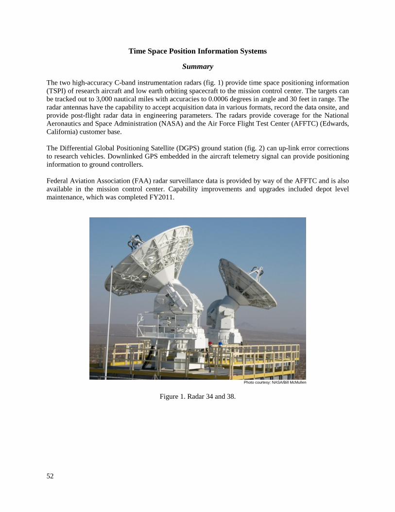
52
Time Space Position Information Systems
Summary
The two high-accuracy C-band instrumentation radars (fig. 1) provide time space positioning information (TSPI) of research aircraft and low earth orbiting spacecraft to the mission control center. The targets can be tracked out to 3,000 nautical miles with accuracies to 0.0006 degrees in angle and 30 feet in range. The radar antennas have the capability to accept acquisition data in various formats, record the data onsite, and provide post-flight radar data in engineering parameters. The radars provide coverage for the National Aeronautics and Space Administration (NASA) and the Air Force Flight Test Center (AFFTC) (Edwards, California) customer base. The Differential Global Positioning Satellite (DGPS) ground station (fig. 2) can up-link error corrections to research vehicles. Downlinked GPS embedded in the aircraft telemetry signal can provide positioning information to ground controllers. Federal Aviation Association (FAA) radar surveillance data is provided by way of the AFFTC and is also available in the mission control center. Capability improvements and upgrades included depot level maintenance, which was completed FY2011.
Photo courtesy: NASA/Bill McMullen
Figure 1. Radar 34 and 38.

53
ED13-0021-05
Figure 2. DGPS Station.
Contacts
Bill McMullen, DFRC, Code MR, (661) 276-5049

54
Video Systems
Summary
Numerous fixed and mobile camera systems are used to acquire mission video for flight monitoring and safety concerns in the Mission Control Center (MCC). Within these systems, one long-range, broadcast-quality, high-definition optical and infrared tracking system is included. This platform provides both day and night coverage of the local airspace. This system is mounted on a first of its kind Kinto Tracking Mount (KTM) tracking pedestal, using a fiber optic rotary joint to transport high definition (HD) video over 2 km to the Video Control Center (VCC) (fig. 1). Several other camera systems provide close-up coverage of flight line, ramp, and runway areas during a mission. Mission video is routed to the MCC, and other desired locations, by the use of a digital video switcher. Mobile video vans (fig. 2) cover remote locations and relay live-action imagery via a ground video van C-band Telemetry (TM) uplink (microwave) video coverage to the MCC. Downlink video from research or chase aircraft can be received in C-, L-, or S-band frequencies and is also available for display into the MCC.
The VCC records and distributes both standard definition analog and HD video via a 208 x 256 Phillips (Eindhoven, The Netherlands) router and a 64 x 64 HD router. Video can be recorded on a variety of formats to include Beta Superior Performance, D2 digital (slow motion viewing), DVD, and HD recorders. All recorded video is archived for a period of 30 days, unless otherwise directed.
In 2011 the Western Aeronautical Test Range (WATR) group provided advanced range video capabilities to the Air Force Flight Test Center (AFFTC), Long Range Optics (LRO) (fig. 3), infrared (IR), and ramp video; upgraded the WATR Mission Control Room with HD mission video displays; and provided engineering and development work, mobile video capability, and HD video tracking system for Runway 04.
ED13-0021001
Figure 1. Video Control Center (VCC).

55
Photo courtesy: NASA/Bill Showers
Figure 2. Mobile video vans.
Photo courtesy: NASA/Bill McMullen
Figure 3. Long Range Optics (LRO).
Contacts
Bill McMullen, DFRC, Code MR, (661) 276-5049

56
RF Communications Systems
Summary
The Western Aeronautical Test Range (WATR) radio frequency (RF) communications system provides the user with a full spectrum of air-to-ground frequency alternatives, to include the HF, VHF, and UHF bands in both AM and FM modulation formats. Users can access the various transceivers using the Digital Integrated Communications Electronics System (DICES) communications panels at any given mission control center (MCC) location. Typically, the MCC has a standard communication panel configuration, giving the user access to five UHF transceivers, two VHF transceivers, and one HF transceiver. Typically, the VHF radios are on omni-directional antennas that operate in the 116 MHz to 152 MHz frequency band. Directional Yagi antennas, operating in the frequency range of 121 MHz to 135 MHz, can be configured for use when greater performance gain is required. The VHF radios (fig. 1) have a fixed RF power out of 28 watts at the transmitter.
The UHF radios (fig. 1) are normally configured on omni-directional antennas, and operate in the frequency range of 225 MHz to 399 MHz. The standard UHF radio RF power output is 20 watts. However, a long-range UHF system, comprising of a pre-amplifier, external 100-watt power amplifier, and the choice of a high-gain omni-directional antenna or directional tracking (parabolic) antenna is available. An HF transceiver is offered, and is configured to a steerable high-gain log periodic (LP) antenna, operating in the 2 to 30 MHz band, with a transmit output power of 1000 watts. The communications facility has also incorporated two wideband radio systems, operating on any frequency between 2 MHz to 1000 MHz, with AM or FM modulations available, and up to 250 watts of transmit power. Lastly, the communications facility (fig. 2) has integrated four VHF, 500 watt FM transceiver systems used in support of the International Space Station (ISS).
In 2011, the WATR added a high-gain communications capability through the dish replacement for local flight out to low Earth orbit (LEO) coverage; the retractable 80-foot steel tower systems supporting UHF/VHF and flight termination systems (FTS); emergency satellite communications and Center emergency communications systems; and expanded system remote control capability out to WATR range support sites.
EC99-45290-28
Figure 1. VHF/UHF Communications Radios.
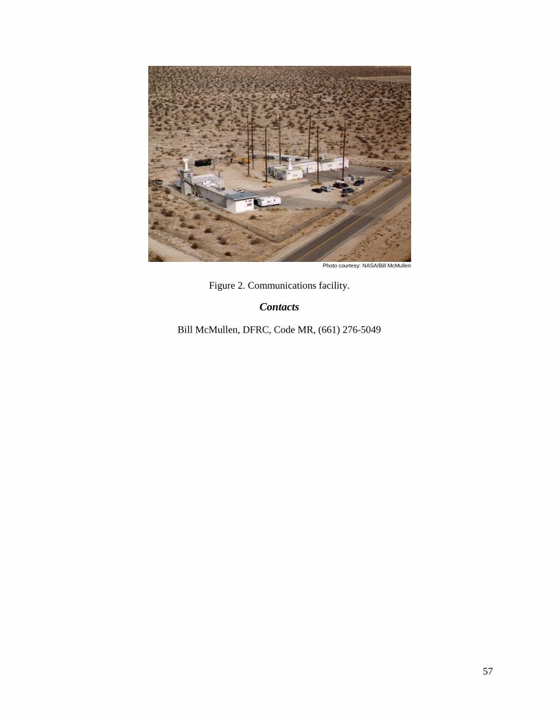
57
Photo courtesy: NASA/Bill McMullen
Figure 2. Communications facility.
Contacts
Bill McMullen, DFRC, Code MR, (661) 276-5049
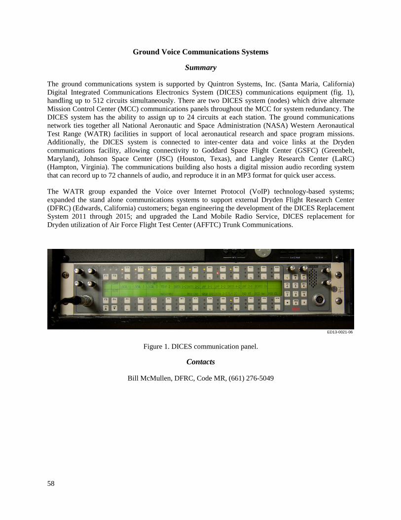
58
Ground Voice Communications Systems
Summary
The ground communications system is supported by Quintron Systems, Inc. (Santa Maria, California) Digital Integrated Communications Electronics System (DICES) communications equipment (fig. 1), handling up to 512 circuits simultaneously. There are two DICES system (nodes) which drive alternate Mission Control Center (MCC) communications panels throughout the MCC for system redundancy. The DICES system has the ability to assign up to 24 circuits at each station. The ground communications network ties together all National Aeronautic and Space Administration (NASA) Western Aeronautical Test Range (WATR) facilities in support of local aeronautical research and space program missions. Additionally, the DICES system is connected to inter-center data and voice links at the Dryden communications facility, allowing connectivity to Goddard Space Flight Center (GSFC) (Greenbelt, Maryland), Johnson Space Center (JSC) (Houston, Texas), and Langley Research Center (LaRC) (Hampton, Virginia). The communications building also hosts a digital mission audio recording system that can record up to 72 channels of audio, and reproduce it in an MP3 format for quick user access.
The WATR group expanded the Voice over Internet Protocol (VoIP) technology-based systems; expanded the stand alone communications systems to support external Dryden Flight Research Center (DFRC) (Edwards, California) customers; began engineering the development of the DICES Replacement System 2011 through 2015; and upgraded the Land Mobile Radio Service, DICES replacement for Dryden utilization of Air Force Flight Test Center (AFFTC) Trunk Communications.
ED13-0021-06
Figure 1. DICES communication panel.
Contacts
Bill McMullen, DFRC, Code MR, (661) 276-5049

59
Data Distribution Systems
Summary
The data distribution systems (fig. 1) link the Western Aeronautical Test Range (WATR) systems with internal and external support and/or user facilities in support of real-time mission data and monitoring. Capabilities include the WATR video center switching system; the Aeronautical Tracking Facility (ATF)-1 data processing rack, which provides a direct data link to Goddard Space Flight Center (GSFC) (Greenbelt, Maryland); data quality monitoring; Viterbi 1/3 and 1/2 rate decoding; and command uplink modulation processing. Other capabilities provided through the data distribution systems include data distribution patching and fiber infrastructure; a direct T-1 link between Point Mugu Naval Air Station and ATF-1 for radar data transmission/reception; OC-3 fiber link between the Air Force Flight Test Center and the Dryden Flight Research Center (DFRC) (Edwards, California) for telemetry (TM), video, voice, and radar data distribution; National Technology Refresh (NTR) system; and a voice communication distribution system.
The WATR group maintained the current capabilities and upgraded the Apcom distribution amplifiers.
ED13-0021-08 ED13-0021-09
ED13-0021-10
ED13-0021-07
Figure 1. Data distribution racks.
Contacts
Bill McMullen, DFRC, Code MR, (661) 276-5049

60
WATR Mobile Operation Facility Systems
Summary
The Western Aeronautical Test Range (WATR) mobile operational facilities (MOF) (fig. 1) provide diverse support capabilities and systems. MOF systems are available for rapid deployment to a specified location on short notice. These systems provide radio-frequency communication, video and telemetry tracking support, and telemetry tracking for test missions outside local airspace boundaries.
The WATR mobile operational facilities included the following capabilities: • 35-ft semi-trailer (fig. 2) equipped with 6-ft telemetry antenna (L-band uplink, L/S-band receive),
Differential Global Positioning System (DGPS), UHF/VHF radio and intercom system, two mobile 4-foot trailer-mounted systems, standalone mobile telemetry systems (fig. 3), and 4- or 6-foot antennas (L-band uplink, L/S-band receive).
• Several user trailers and/or custom ground control stations. The following improvements and upgrades were noted in FY2011:
• Provided new WATR Mobile Operations Center for project build-up and deployment capabilities. • Remote project user site with interface (fiber/copper) to WATR and Air Force Test Center
(AFTC) facilities.
New mobile telemetry facility, L-band uplink, L/S-band receive), DGPS, UHF/VHF radio and intercom system available for WATR and AFFTC project support.
Photo courtesy: NASA/Bill McMullen
Figure 1. Mobile Systems Operations Center.

61
Photo courtesy: NASA/Bill McMullen
Figure 2. Mobile Telemetry Support Trailer.
Photo courtesy: NASA/Bill Showers
Figure 3. Mobile Suite Case Telemetry Systems.
Contacts
Bill McMullen, DFRC, Code MR, (661) 276-5049

62
Real-Time Data Processing/Monitoring Systems
Summary
Data is acquired and merged from multiple sources in various formats to a single, time-correlated, composite stream for processing, distribution, real-time display, and storage archival (fig. 1). Segments of post-mission data are immediately available on portable media. Post-flight radar data is provided in the appropriate engineering parameters. The mobile operations system can process and display data onsite, or reformat data and transmit it to a customer’s facility. The Western Aeronautical Test Range (WATR) Mission Control Center (MCC) (fig. 2) provides real-time mission operations for test conductors, research engineers, range safety, and other project personnel. The MCC is used for monitoring of data for flight safety and mission success with data analysis for in-flight test point clearance. The real-time data processing/monitoring systems include the following capabilities:
• Capable of up to 6 Pulse Code Modulation (PCM) and custom data streams. • Capable of up to 1,000,000 samples per second of data. • Handles both telemetry and radar data. • Capable of six telemetry streams from 1 to 30 Mbps each. • Accommodates complex user computational models. • Provides data archival.
The following improvements and upgrades were noted in FY2011:
• WATR Integrated Next Generation System (WINGS) Cache Data Server (CDS) Replacement. • Mission Control room video upgrades to high definition video wall. • Upgraded the Digital Integrated Communications Electronics System (DICES) development and
engineering work.
ED07-0093-07
Figure 1. Telemetry Radar Acquisition Processing System (TRAPS) 2.

63
Photo courtesy: NASA/Robert Guere
Figure 2. Mission Control Center 2.
Contacts
Bill McMullen, DFRC, Code MR, (661) 276-5049

64
Range Safety Ground Systems
Summary
Range Safety Officers monitor flight-critical data as well as time-space positioning data. The command transmitter systems (CTS) (fig. 1) along with the command panels located in the control room are used for flight termination of errant vehicles. The Range Safety Ground Systems consist of two pairs of transmitters with multiple command panels for activation; Global Real-Time Interactive Map (GRIM) for situational awareness; legacy and Enhanced Flight Termination System (EFTS) capability; and dual sites for dual mission support capability.
The following improvements and upgrades were noted in FY2011: • Upgraded situational awareness display capability with commercial off the shelf (COTS)
solution. • Upgraded Range Safety Impact Predictor program and displays. • Installed EFTS capability (Phase 1) as Air Force Flight Test Center (AFFTC) and Western
Aeronautical Test Range (WATR) support capability (fig. 2).
Photo courtesy: NASA/Robert Guere
Figure 1. Flight Termination System (FTS) Control.
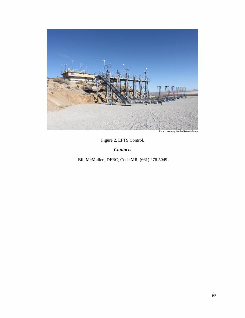
65
Photo courtesy: NASA/Robert Guere
Figure 2. EFTS Control.
Contacts
Bill McMullen, DFRC, Code MR, (661) 276-5049

66

67
Technical Laboratory Services
Technical Laboratory Services, Code MT, supports structures engineering in the Flight Loads Laboratory and simulation engineering in the Research Aircraft Integration Facility. The core group consists of electronic technicians and engineering technicians (mechanical), who perform the operations, maintenance, buildup, instrumentation, testing, troubleshooting, and data collection of test articles, flight hardware, flight simulators, and the laboratory test equipment.
The Dryden Flight Research Center (Edwards, California) Flight Loads Laboratory (FLL) is a unique lab for structural and thermal testing of aerospace structures. The Technical Support Services Branch supports the FLL in the following discipline areas:
• Loads Calibration Testing including test fixture build up, data acquisition (DA) and display systems, load application build-up, load control, instrumentation installation, and test support.
• Ground Vibration Testing including test fixture build up, DA and display systems, soft support maintenance and load checks, control, instrumentation installation, and test support.
• Hot Structures Testing including test fixture, heater and oven build, DA, display, and thermal control, systems load application build-up, load control, installation of high-temperature instrumentation, and test support.
• Chamber for Large-Scale Hot Structures Testing including support operating and maintaining gaseous and Liquid Nitrogen systems power control cabinets, load application and control, custom-built oven system instrumentation, and test support.
• Instrumentation installation including strain, temperature, heat flux, and fiber optic measurements sensors on advanced materials including: metallic, metal matrix composites, super alloy honeycomb, C/C and C/SiC.; attachment techniques include epoxy-based adhesives, ceramic and graphite cements, and plasma and Rokide thermal spraying.
The Technical Laboratory Services team supported simulation engineering in the Research Aircraft Integration Facility throughout 2011. This versatile team worked on aircraft that ranged from hosted programs to reimbursable work and those that belonged to our long-standing partners. The Technical Lab provided support in simulation systems fabrication, assembly, maintenance, modification, installation, and operation; assisted in the development of simulators and control rooms; performed system hardware integration, simulation system calibration, circuit card build-up, and mechanical buildup and modifications for the Simulation Group. The core team consisted of electronic technicians and engineering technicians (mechanical), who performed the operations, maintenance, buildup, instrumentation, testing, troubleshooting, and data collection of test articles, flight hardware, flight simulators, and the laboratory test equipment.

68
Structurally Integrated Thermal Protection System
Summary As part of a multi-center effort and private industry partnership, basic manufacturing, testing, and analysis technologies for a new thermal protection system (TPS), termed Structurally Integrated Thermal Protection System (SITPS), is being investigated. The vehicle skin is an integrated TPS that is able to carry the mechanical and thermal loads resulting from hypersonic flight and share the loads with adjacent panels.
The Technical Support Services team instrumented an aluminum surrogate panel to be used as a pathfinder for SITPS-2 testing. The team evaluated the performance of the Phase 1 test setups to impart the desired loads that will be required for the SITPS-2 testing, and developed and evaluated the test procedures and data processing procedures for the Phase 2 tests (figs. 1-3).
Figure 1. Torsion test fixture.

69
Figure 2. Four point bending test fixture.
Photo courtesy: NASA/Larry Hudson
Figure 3. Pressure test fixture.
Contacts
Ronnie Haraguchi, DFRC, Code RS, (661) 276-2367
70
Phantom Eye Ground Vibration Test/Structural Moment of Inertia
Summary
The Phantom Eye Ground Vibration Test (GVT)/Structural Moment of Inertia (SMI) was a reimbursable effort to design a soft suspension system for a High Altitude Long Endurance (HALE) vehicle. The Technical Support Services team used bungees as soft springs to provide adequate dynamic isolation, and performed creep and dynamic characterization tests to evaluate appropriate design parameters for bungees.
The team used test instrumentation and data acquisition system to record displacement data and provided test support for test setup/tear down and execution of testing. The team successfully performed critical lifts, extensive creep and dynamic characterization testing on parallel spring setup that combined spring types 1 and 2, and supported the holdback test.
Contact
Ronnie Haraguchi, DFRC, Code RS, (661) 276-2367

71
G-III Aircraft
Summary
The skilled technicians in the Technical Services support group performed several upgrades to the G-III aircraft (T/N 804) (fig. 1) in 2011. The Technical Services support group also sent a team to the Dryden Aircraft Operations Facility (DAOF) in Palmdale, California to install strain gages on the VHF antenna panel to help resolve stress issues, installed wing thermocouples for air temperature base line flights, built a small data acquisition system (DACS) to support flight tests, and installed 24 strain gages on the Adaptive Compliant Trailing Edge (ACTE) flap.
ED-12-0191-12
Figure 1. National Aeronautics and Space Administration Dryden Gulfstream G-III aerodynamics research test bed aircraft.
Contact
Ronnie Haraguchi, DFRC, Code RS, (661) 276-2367

72
Photogrammetry System to Temecula Temporary Duty
Summary
Photogrammetry is an optical technique for measuring strains and spatial deformations. High-speed cameras support both static and dynamic testing of coupon specimens to large aircraft (fig. 1). The Technical Services support team sent a technician with equipment to perform photogrammetry of a bladder for a re-entry vehicle. Typical team photogrammetry support consists of operating and maintaining the equipment, test support, and data reduction and processing.
Photo courtesy: Trilion Quality Systems
Figure 1. Basic photogrammetry set up.
Contact
Ronnie Haraguchi, DFRC, Code RS, (661) 276-2367

73
Stratospheric Observatory for Infrared Astronomy
Summary
The Stratospheric Observatory for Infrared Astronomy (SOFIA) activity was a reimbursable effort to install instrumentation to monitor telescope temperatures and cooling system, install resistance temperature detectors (RTDs) on the ground control monitoring cart, install RTDs on the telescope and frame, and make thermocouple (TC) probes to monitor cavity air temperatures (fig. 1). The Technical Services support team provided unique instrumentation expertise making customized TC transducers and specialized expertise installing instrumentation on delicate test articles. The Technical Services support team successfully installed four RTDs onto Liquid Nitrogen (LN2) system ground support equipment, installed 22 RTDs on the telescope assembly and frame, and built 27 customized ultra-fine TCs air probe welding sensors using .0005 mm TCs.
ED-08-029-23
Figure 1. Stratospheric Observatory for Infrared Astronomy telescope cavity.
Contact
Ronnie Haraguchi, DFRC, Code RS, (661) 276-2367

74
Dynamic Inertia Measurement Test
Summary
The primary objective of this project was to adapt the Dynamic Inertia Measurement (DIM) test method for accurately measuring, in a practical manner, the rigid-body mass matrices (ten unique terms) of large aerospace vehicles such as aircraft, possibly weighing as much as 20,000 to 40,000 lb using six direction of freedom force/moment transducers. The Technical Services support team successfully performed working load checks on 60,000 lb capacity soft supports and provided set up and tear down of the complex systems (fig. 1).
Figure 1. Iron Bird Soft Support and Jack Footprint Diagram.
Contact
Ronnie Haraguchi, DFRC, Code RS, (661) 276-2367
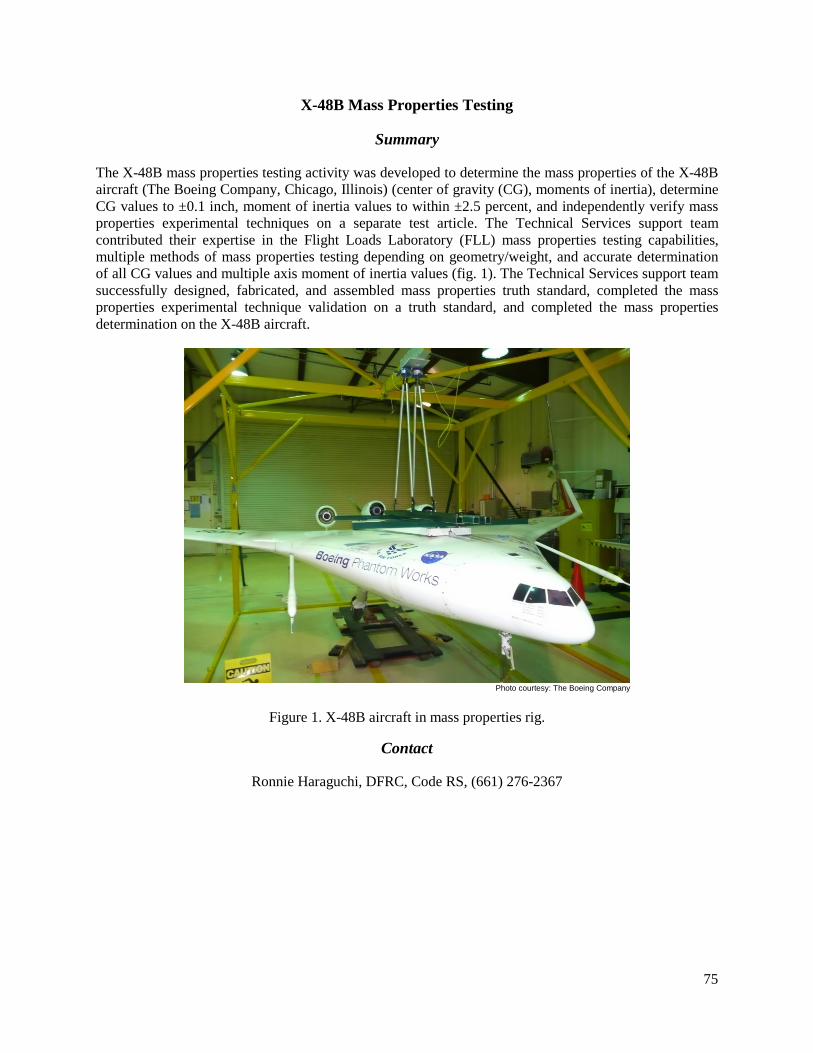
75
X-48B Mass Properties Testing
Summary
The X-48B mass properties testing activity was developed to determine the mass properties of the X-48B aircraft (The Boeing Company, Chicago, Illinois) (center of gravity (CG), moments of inertia), determine CG values to ±0.1 inch, moment of inertia values to within ±2.5 percent, and independently verify mass properties experimental techniques on a separate test article. The Technical Services support team contributed their expertise in the Flight Loads Laboratory (FLL) mass properties testing capabilities, multiple methods of mass properties testing depending on geometry/weight, and accurate determination of all CG values and multiple axis moment of inertia values (fig. 1). The Technical Services support team successfully designed, fabricated, and assembled mass properties truth standard, completed the mass properties experimental technique validation on a truth standard, and completed the mass properties determination on the X-48B aircraft.
Photo courtesy: The Boeing Company
Figure 1. X-48B aircraft in mass properties rig.
Contact
Ronnie Haraguchi, DFRC, Code RS, (661) 276-2367

76
HyperSonic Vehicle Test Article
Summary
The HyperSonic Vehicle Test Article (HSVTA) was a reimbursable United States Department of Defense (DoD) program involving the mechanical load and thermal testing of a forebody section of a hypersonic missile. The Technical Services support team contributed their knowledge of the Flight Loads Lab (FLL) mechanical loading and hot structures testing capabilities, mechanical load systems, inert test chamber, radiant heating systems, test data acquisition systems, high-temperature instrumentation, and pulsed thermography non-destructive evaluation system. The team successfully completed thermal soak and thermal shock profile testing (fig. 1), completed post-test thermography inspection, and delivered all the test data to the customer.
Photo Courtesy: NASA/Larry Hudson
Figure 1. HSVTA in thermal test set up.
Contact
Ronnie Haraguchi, DFRC, Code RS, (661) 276-2367
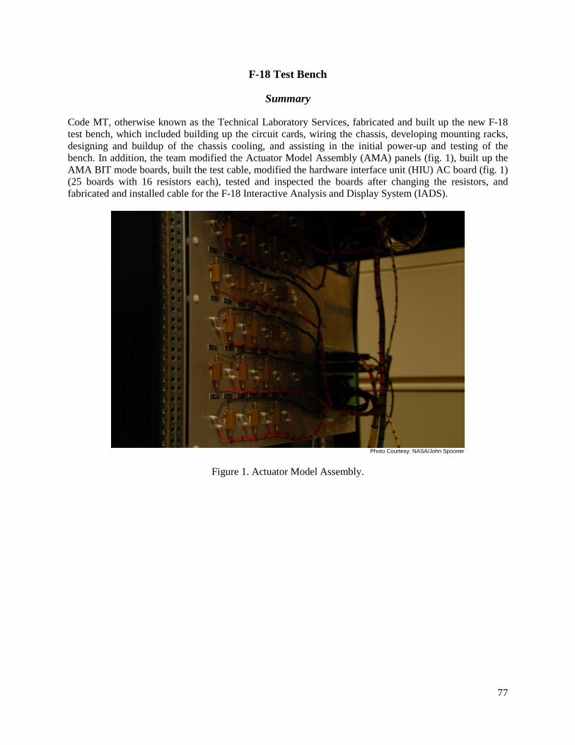
77
F-18 Test Bench
Summary
Code MT, otherwise known as the Technical Laboratory Services, fabricated and built up the new F-18 test bench, which included building up the circuit cards, wiring the chassis, developing mounting racks, designing and buildup of the chassis cooling, and assisting in the initial power-up and testing of the bench. In addition, the team modified the Actuator Model Assembly (AMA) panels (fig. 1), built up the AMA BIT mode boards, built the test cable, modified the hardware interface unit (HIU) AC board (fig. 1) (25 boards with 16 resistors each), tested and inspected the boards after changing the resistors, and fabricated and installed cable for the F-18 Interactive Analysis and Display System (IADS).
Photo Courtesy: NASA/John Spooner
Figure 1. Actuator Model Assembly.

78
Photo Courtesy: NASA/John Spooner
Figure 2. HIU AC board.
Contact
Gary Kellogg, DFRC, Code ME, (661) 276- 3779
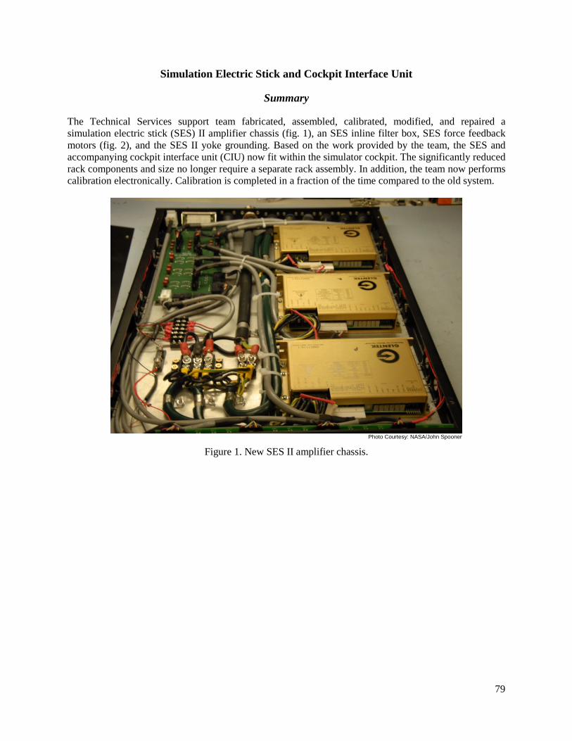
79
Simulation Electric Stick and Cockpit Interface Unit
Summary
The Technical Services support team fabricated, assembled, calibrated, modified, and repaired a simulation electric stick (SES) II amplifier chassis (fig. 1), an SES inline filter box, SES force feedback motors (fig. 2), and the SES II yoke grounding. Based on the work provided by the team, the SES and accompanying cockpit interface unit (CIU) now fit within the simulator cockpit. The significantly reduced rack components and size no longer require a separate rack assembly. In addition, the team now performs calibration electronically. Calibration is completed in a fraction of the time compared to the old system.
Photo Courtesy: NASA/John Spooner
Figure 1. New SES II amplifier chassis.

80
Photo Courtesy: NASA/John Spooner
Figure 2. Modified force feedback motor assembly.
Contact
Gary Kellogg, DFRC, Code ME, (661) 276-3779

81
Mobile Cockpit Build
Summary
For the mobile cockpit build, the Technical Services support team assembled, fabricated, and integrated all hardware including the computers and display units into a rolling cockpit (figs. 1 and 2). Additionally, they prepared the unit for the Paint Shop, assembled the unit after it was painted, prepared the unit for shipping, and set up a mobile simulation in the Remotely Augmented Vehicles (RAV) Lab.
Photo Courtesy: NASA/John Spooner
Figure 1. Mobile cockpit.

82
Photo Courtesy: NASA/John Spooner
Figure 2. Mobile cockpit.
Contact
Gary Kellogg, DFRC, Code ME, (661) 276- 3779

83
Blended Wing Body (X-48B) Aircraft
Summary
The Technical Services support team created all specialized cabling to computers, networks, chassis, and all interfacing devices for the Blended Wing Body X-48B aircraft (The Boeing Company, Chicago, Illinois) (fig. 1). The Technical Services support team also provided cabling for power, all of the simulators flight instruments, and controls (fig. 2).
Photo Courtesy: NASA/John Spooner
Figure 1. X-48 simulator cockpit.

84
Photo Courtesy: NASA/John Spooner
Figure 2. Instrumentation cabling.
Contact
Gary Kellogg, DFRC, Code ME, (661) 276- 3779

85
Consolidated Information Technology Center (CITC) The Consolidated Information Technology Center (CITC) provides a secure environment for all of Dryden's consolidated information technology (IT) services. The CITC was designed to lower operating costs, conserve energy and water, be safer and healthier for occupants, and reduce greenhouse gas emissions. The following information on the CITC is taken from: http://www.nasa.gov/centers/ dryden/pdf/695829main_CITC_annual_report_2011.pdf (accessed February 11, 2013).
Dryden’s Consolidated Information Technology Center replaced antiquated facilities and consolidated all IT services into one 40,000 square feet facility. It provides a secure environment and enables us to do more. In addition, the costs of this building over its life cycle will be much lower.
Designed by the Development One Inc., architectural firm of Santa Ana, Calif., the new building is a state-of-the-art facility that meets both current and anticipated future information technology requirements. The building provides energy conservation, recycling, and water efficiency. Dryden's facility is a silver building, a second of four tiers used to describe new Leadership in Energy and Environmental Design, or LEED Buildings, as designated by the U.S. Green Building council.
It also marks the first "green" building to be constructed at Dryden. The new building consists of steel-frame, concrete masonry construction, with aluminum and glass wall elements and perforated metal overhangs. The new facility is in line with agency-wide goals to consolidate IT resources and building more environmentally sound buildings.
The facility is expected to improve the overall reliability of IT service delivery to Dryden customers. It was designed as a Tier III building, which means there is redundant power and cooling for everything, so any one component failure doesn't impact IT service delivery.
The new information technology center is a model for NASA data centers of the future.
Communication Services • Network (Wired and wireless networks, Remote Access (VPN), Video over IP,
Video Portal) • Firewall Management • Cable Plant • Voice (Telephones ; VoIP, Secure Phones, Analog Phones) • Land Mobil Radio (LMR) • Overhead paging • E911/CER-Center Emergency Response
End User Services (Via ACES) • Computers (PC/MAC/Linux desktop and Laptops) • Mobile Devices (Cell Phones, Smartphones, Tablets (iPad), Air-Cards/MiFi Mobile
Hot Spots) • Printers (Network Printers, Multi-function Devices (MFDs) • Other (ACES Product Catalog, Loner Pool, WebEx, Home use Software)

86
Direct Mission Support • IT Systems Engineering (IT Consulting, IT Solutions Architects, System Security
Plan Support) • Dryden Local Service Desk
Multimedia Services • Photography (In Flight and Standard, production, archive) • Graphics • Video (In Flight, production, Conf Room A/V design, Archive) • Reproduction (Quick Copy Services)
Data Center Services • Hosting (Computing Services, Data Storage, Virtual Machines) • Housing (Tier 3 Center; Rack Space, Cooling, Power) • Value –added Services (System Administration, Lab and Engineering seat
Management, Data Management and Delivery—Flight Data)
Application Services • Application Development • Content Management • Application Administration
Security Services • IT Security Policy • Assessment and Authorizations (Security Plan Management, A&A Scheduling and
Coordination) • Identity, Credential, and Access Management (NAMS Workflow Development) • Monitoring (Intrusion Detection, Incident Response) • Threat Vulnerability (Vulnerability Scanning, Patch Management)
Contact Information Lawrence Freudinger Chief Information Officer Office of the CIO Dryden Flight Research Center 661-276-3542 E-mail: [email protected]

87
Flight Loads Laboratory The Flight Loads Laboratory (FLL) is part of the Aeronautics Test Program (ATP), which ensures that wind tunnels, air-breathing propulsion test facilities, and flight operations services at the National Aeronautics and Space Administration (NASA) are available to government, corporations, and institutions. The following information on the FLL is taken from http://www.aeronautics.nasa.gov/atp/facilities/fll/M187015fll_print_ 508.pdf (accessed February 11, 2013).
The Flight Loads Laboratory (FLL) was constructed at NASA’s Dryden Flight Research Center in 1964 as a unique national laboratory to support flight research and aircraft structures testing. FLL personnel conduct mechanical-load and thermal tests of structural components and complete flight vehicles in addition to performing calibration tests of vehicle instrumentation for real-time determination of flight loads. Mechanical loads and thermal conditions can be applied either separately or simultaneously to simulate combined thermal-mechanical load conditions. FLL personnel also conduct modal survey and structural mode interaction testing to support structures research and assess aircraft for flutter airworthiness.
The FLL’s experienced and skilled technical staff provides expertise in ground and flight test design and operations; load, stress, dynamic, and thermal analysis; and instrumentation and measurement systems development. This expertise, coupled with a large array of capital equipment and advanced data acquisition and control systems, make the FLL an ideal laboratory for research and testing of aerospace vehicles and structures flying in the subsonic through hypersonic flight regimes.
Facility Benefits • Single facility capable of conducting mechanical, thermal, and structural dynamics
research and testing. • Combined thermal, mechanical, and structural dynamics testing allows for study of
the effects of these combined conditions. • Verification of static or dynamic structural performance at realistic flight
temperatures. • Conventional and high-temperature instrumentation for ground and flight testing. • Fiber optic sensing technology for real-time distributive strain and temperature
sensing. • Photogrammetry system for non-contact strain and deformation measurements. • Transient thermography for non-destructive evaluation of materials and structures. • Location allows direct access to Dryden Flight Research Center and Edwards Air
Force Base taxiways and runways, including the Rogers Dry Lake. Facility Applications • Component and full vehicle testing • Thermal, mechanical, and structural dynamics testing • Key projects supported: X-15, X-24, YF-12, Space Shuttle, F-111 AFTI/MAW, X-
30, F-15 ACTIVE, X-37, X-38, X-43, Orion Crew Module, F-18 AAW, E-2C Advanced Hawkeye, Global Observer

88
Facility Characteristics High-Bay Dimensions 164 ft wide by 120 ft deep by 40 ft high
Mechanical Testing Capability Proof and loads calibration testing of aircraft
components and structures Channels 84 channels of hydraulic load control Loading equipment
Actuators and load cells for loads up to 300 000 lbf, load frames (220k, 100k, 25k lbf)
Thermal Testing Capability Large-scale air and inert atmosphere testing Channels 264 channels of independent model-free
adaptive control Temperature range
-320 to >3000°F
Heating systems Quartz lamp and graphite heating Support systems Large nitrogen atmosphere test chamber,
4000 gal liquid nitrogen supply, thermal-spray systems
Structural Dynamics Testing Capability Modal survey and structural mode interaction
testing Systems Portable data acquisition with 336 channels Soft support Self-jacking system (60k lb), overhead suspension
systems (up to 14k lb) Sensors Room- and high-temperature, seismic and low
frequency accelerometers
Data Acquisition and Monitoring Systems Data acquisition 1920 data channels (expandable) Fiber optic data acquisition
Distributive strain/temperature systems with 10’s of thousand sensors at sample rates up to 100 sps
Data display Interactive Analysis and Display System (IADS) Video Networked video system Communication Wireless communication
Contact Information: Thomas Horn Chief, Aerostructures Branch Dryden Flight Research Center 661–276–2232 E-mail: [email protected] Larry Hudson FLL Chief Test Engineer Dryden Flight Research Center 661–276–3925 E-mail: [email protected]

89
Research Aircraft Integration Facility (RAIF) The Research Aircraft Integration Facility (RAIF) is part of the Aeronautics Test Program (ATP), which ensures that wind tunnels, air-breathing propulsion test facilities, and flight operations services at the National Aeronautics and Space Administration (NASA) are available to government, corporations, and institutions. The following information on the RAIF is taken from: http://www.aeronautics.nasa.gov/atp/facilities/raif/ M187016RAIF_dsi.pdf (accessed February 11, 2013).
NASA Dryden’s Research Aircraft Integration Facility (RAIF) provides the ability to seamlessly integrate simulation and vehicle systems under one roof. This one-of-a kind facility can simultaneously support a wide variety of advanced, highly integrated aerospace vehicles through all phases of a research program, from conceptual design to flight.
The RAIF offers high-fidelity six degree of freedom, batch, and real-time flight simulation capabilities. The facility provides support for system integration and closed-loop verification and validation testing of components, systems, and entire vehicles. Also available are complete aircraft ground-support services, including all electrical, hydraulic, and cooling-air systems required for vehicle-system integration, functional checks, and routine aircraft maintenance.
Facility Benefits • Provides research teams with the means to conduct efficient, thorough testing of
advanced, highly integrated research vehicles • Provides configurable systems for all facets of a research program including
simulation software, hardware, and direct vehicle support infrastructure • Provides scalable systems for
− Evaluation of design concepts − Piloted or vehicle- and hardware-in-the-loop operations − Combined systems testing − System integration and full mission support
− Control-room training, mission planning, and data analysis • Can be configured to accommodate up to 11 simulation laboratories • Can be tailored to support varying access and security requirements within each lab • Offers audio, video, and data connectivity to any of the six facility hangar bays as
well as to the Dryden Mission Control Center
Facility Applications The RAIF has been a critical asset for the successful implementation of some of the nation’s most revolutionary and valuable research efforts. These efforts supported a variety of research vehicles that cover subsonic through hypersonic flight regimes, including X–43A(Hyper-X), F–18, F–15, and C–17. Data Acquisition and Processing • Simulation software capabilities: − High-fidelity, 6-DOF simulation packages − Software simulation package supports both real-time (human-in the-loop and
hardware-in-the-loop) and non-real-time (desktop) operations − Common, configurable software supporting multiple projects − Multiple operating system platforms (Solaris and Linux) − Support multiple programming languages (FORTRAN, C, C++, Java, and Ada)

90
− Multiview out-the-window graphics with heads-up displays (HUD) and articulated three-dimensional models of flight vehicles
− Operable by one person • Simulation hardware capabilities:
− Dedicated or configurable fixed-base engineering simulation cockpits − Configurable hardware interface units for vehicle-systems integration testing − Common configurable hardware to support multiple projects − Configurable Simulation Electric Stick (SES) and rudder pedal systems − Configurable Cockpit Interface Unit (CIU) − Flight hardware interface capability (MIL–STD–1553, ARINC 429, and analog
and discrete signals)
Characteristics • Test bays 1, 2, and 3 provide over 30,000 square feet of hangar space • The 225-by 135-ft hangar is accessible through a split 225-by 50-ft door • Test bays 4 and 5 provide a total of 12, 500 square feet of hangar space • Test bay 6 is a single-vehicle bay providing 1000 square feet of hangar space that can
be configured to support programs with more stringent security requirements • Test bay data and communication connectivity to RAIF simulation labs and Dryden
control rooms • Co-located vehicle maintenance support staffing • Co-located program and vehicle engineering and technician staff • Complete vehicle support systems (aircraft cooling, electrical power, and hydraulics) • Electrostatic Discharge Association (ESD)certified support labs Contact Information Gary V. Kellogg Chief, Simulation Engineering Branch Dryden Flight Research Center 661-276-3779 E-mail: [email protected]

91
Western Aeronautical Test Range (WATR) The Western Aeronautical Test Range (WATR) is part of the Aeronautics Test Program (ATP), which ensures that wind tunnels, air-breathing propulsion test facilities, and flight operations services at the National Aeronautics and Space Administration (NASA) are available to government, corporations, and institutions. The following information on the WATR is taken from: http://www.aeronautics. nasa.gov/atp/facilities/watr/M187017_watr_508.pdf (accessed February 11, 2013).
NASA Dryden Flight Research Center’s Western Aeronautical Test Range (WATR) supports aerospace flight research and technology integration, space exploration concepts, airborne remote sensing and a wide variety of science missions.
The WATR supplies a comprehensive set of resources for the control and monitoring of flight activities, real-time acquisition and reduction of research data, and effective communication of information to flight and ground crews.
Facility Benefits • Precision RADAR provides time space positioning information (TSPI) on research
vehicles, International Space Station (ISS), and other targets, including satellites. • Fixed and mobile telemetry antennas receive real-time telemetry data and video and
have the capability to transmit uplink commands to research vehicles. • The processed data is displayed at the engineering stations in the mission control
center and archived in a post-flight storage area. • Audio communication networks support aeronautics research and space operations in
the WATR, covering a broad frequency spectrum for transmitting and receiving voice communications and flight termination signals for unmanned aerial vehicles.
• Video monitoring provides real-time and recorded data for the control and safety of flight test missions.
Facility Applications The WATR supports aerospace flight research and technology integration, space exploration concepts, airborne remote sensing and science missions, as well as the ISS operations.
Characteristics WATR Mission Control Centers • 26 test engineering stations in MCC1 and 19 in MCC2 including: − Communications
(radio and intercom) panels − Video monitors, − Weather data − IRIG-B timing − Specialized graphics displays.
• Range and mission control, test operations, range safety and test director consoles provide critical analysis and display capabilities.
• The WATR mobile systems • Available for rapid deployment to a specified location on short notice. These systems
provide: − Radio-frequency communication − Video and telemetry-tracking support − Telemetry tracking for test missions outside local airspace boundaries − Uplink commands to research vehicles

92
Data Acquisition and Processing Data is acquired and merged from multiple sources in various formats to a single, time-correlated, composite stream for processing, distribution, real-time display and storage archival. Segments of post-mission data are immediately available on portable media. Post-flight RADAR data can also be provided if reverted. The mobile operations system can process and display data onsite, or reformat data and transmit it to a customer’s facility.
Telemetry WATR telemetry tracking systems consist of: • Multiple fixed antennas and available mobile systems − Downlinked telemetry and video signals in C-, L-, and S-bands. − Uplinked commands in either L-or S-bands. − Track targets from horizon to horizon. − Certified for full on-orbit capability. Downlinked telemetry may be received in either analog or digital format.
Communications Radio Frequency (RF) Communications: • More than 40 ultra-high-frequency (UHF), very-high-frequency (VHF), and high-
frequency (HF) transmitter receivers. • UHF flight termination systems, for IRIG or EFTS based systems • Extensive range intercommunication system consists of: − Trunk lines − Public address systems − Commercial telephone systems − Military ground-communication networks. • An integrated communications system, including: − Ground-based fiber optics. −
Orbital satellites • Satellite Communication capability. − Used to relay telemetry, radar, audio and video data
RADAR • Two high-accuracy, C-band instrumentation radars. • Track targets out to a distance of 3,000 nautical miles with accuracies to 0.0006
degrees in angle and 30 feet in range. • Video • Numerous fixed and mobile camera systems for flight monitoring, safety and mission
control. • Long-range, broadcast-quality, high-definition optical system providing day and
night (including infrared) coverage • Coverage of the flight line, ramp areas and runways. • Mobile video vans − Capability to relay live-action imagery via microwave links. − Capability to relay live action imagery via ground video van C-Band TM uplink. − Downlinked video from research vehicles or chase aircraft can be received in C-, L-, or S-band frequencies. − Video recording is provided on Super VHS, Beta Superior Performance, DVD, and other high-definition media.

93
Contact Information Darryl Burkes WATR Project Manager Dryden Flight Research Center 661–276–2517 E-mail: [email protected]

94

95
2011 AWARDS, RECOGNITION, AND CONFERENCE PAPERS
NASA Medals
Exceptional Service Medal (ESM) William D. McMullen
Exceptional Leadership Medal (ELM) Roberta B. Sherrard
Group Achievement Award DFRC Full-Scale Advanced Systems Testbed/Model Reference Adaptive Control Research Team (FAST/MRAC) NASA/Northrop Grumman Global Hawk Development Team Orion Abort Flight Test Pad Abort-1 Team 2011 NASA Small Business Prime Contractor of the Year Arcata Associates
Dryden Peer Awards
Can-Do Attitude Award Theresia Pettit, Arcata
Mission Support – Education/Outreach/Volunteer Debbie Phillips, Arcata
Mission Support – Information Technology Dennis DaCruz
Pride in NASA (PIN) Award Carla Thomas, Arcata
Unsung Hero Award Theresia Pettit, Arcata
Certificates of Appreciation, Arcata Associates Jason Abueg, Carl Baccus, Zach Bowen, Daniel Burgdorf, Jennifer Campbell, Anthony Canada, Greg Cole, Monroe Conner, Anne Crowell, Richard Courtois, Ryan Daily, Kevin Dolber, Gary Edwards, Dave Faust, Joe Fernandez, Tim Fisher, Denise Harris, Joe Innis, Michael Johns, Todd Kunkel, Robert Law, Daniel Lehan, Lori Losey, Gustavo Marmolejo, David Matthews, Samantha McGovern, Todd Mostyn, Steve Parcel, Tim Peters, Emily Peterson, Theresia Pettit, Debbie Phillips, John Pitre, Robert Racicot, Brady Rennie, Jim Ross, James Round, Craig Sayler, Josh Schweitzer, Warren Shearer, Jack Sheldon, Steve Simison, Brian Soukup, Carla Thomas, Thomas Tschida, Dave Upton, Jesus Vazquez, Donna White, Tracey Pardue, Jennifer Wilson, John Wong, Jesse Zamarripa

96
Conference Papers Published in 2011 Kevin Knudtson, Alice Park, Bob Downing, Jack Sheldon, Robert Harvey, and April Norcross, “Wings Chapter 10 Tool,” 2011 International Telemetering Conference (ITC/USA), Las Vegas, Nevada, October 24-27, 2011.