mississipdi canvon 2s2 oil second amendment to first work
TRANSCRIPT

2011 Human Ute Aerial Imagefy Work Plan_________________________ 11/14/20U
Deepwatet Hotizon/MiBsiBBippi Canyon
MississiPDi Canvon 2S2 Oil Second Amendment to First Work Plan for fhA
Collection of Data Related to Beach Usage Along the Coast of the Gulf of McTipn
November 14,2011
First Amendment: December 28,2011
Second Amendment: March 4,2013
Approvals
Approval o f this work plan is for the purposes o f obtaining data f«r the Natural Resource Damage Assessment Each party reserves its tight to produce Its own independent interpretation and analysis o f any data collected pursuant to this work plan.
tOVED:
itive:— g / l i }Date f /
M arch 1 1 , 2 0 1 3
— -------------- Date
y 3 ! \% / i SNOAA Trustee Representative Date
(on behalf o f all other lYustees)
DWH-AR0078740

2011 H um an U se Aerial Im agery Work Plan11/14/2011
Mississippi Canyon 252 Oil Spill
Second Amendment to First Work Plan for the
Colleetion of Data Related to
Beach Usage Along the Coast of the Gulf of Mexico
November 14, 2011
First Amendment; December 28, 2011
Second Amendment: M arch 4, 2013
BackgroundThe First Work Plan for the Collection of Data Related to Beach Usage Along the Coast of the Gulf of Mexico (“Work Plan”; date of the signed plan: November 14, 2011) is a signed cooperative plan covering overflights and the acquisition of aerial images through December 31,2011 and the production and processing of aerial images acquire through December 31, 2011. The first amendment, dated December 28, 2011, extended the overflights and acquisition of aerial images under the Work Plan through March 31, 2012 as well as the production and processing of aerial images acquired through March 31, 2012. This second amendment documents the extension of the Trustees’ overflights and acquisition of aerial images from April 1, 2012 through June 30, 2013, HP’s overflights and acquisition of aerial images from April 1,2012 through September 30, 2012, and the production and processing of aerial images acquired during the respective time periods.
First Work Plan
The first Work Plan is amended or supplemented as follows:
Page 2, “Aerial Imagery”, second paragraph, first sentence - “Within forty-five (45) days of the execution of this Second Amendment, the Parties will exchange all aerial images and corresponding waypoint files (’’digital images”) acquired under their respective overflight protocols between April 1, 2012 and the execution of this Second Amendment.”
Page 3, “Processing of Aerial Images”, subpart a., “Aerial Images Taken Before Execution of Work Plan” - “Within sixty (60) days of the execution of this Second Amendment, the Parties shall share with each other their electronic files depicting the processed photos with all markings attached, along with the data for all images that have been processed between April 1, 2012 and the execution of this Second Amendment.”
DWH-AR0078741
2011 H um an U se Aerial Im agery Work Plan11/14/2011
Page 3, “Processing of Aerial Images”, subpart b., “Aerial Images taken Pursuant to Work Plan” first sentence - “Upon execution of this Work Plan, the Trustees shall deliver the electronic files and data for processed images on the final business day of each month until all of the aerial images taken by each Party pursuant to this Second Amendment have been processed.”
MethodologyOther than the changes identified in Exhibits G and H, the protocols remain the same as described in the original Work Plan.
Data Management and Trnstee OversightOther than the changes identified in Exhibits G and H, the protocols remain the same as described in the original Work Plan.
BudgetingExhibit I contains the Trustees’ projected expenses from January I, 2013 through September 30, 2013. BP has provided NOAA with funding for Tasks 1 and 2. BP has not provided funding for Task 3; however, NOAA has not expended all of the funding (“previously provided funding”) provided by BP pursuant to the original work plan and the first amendment to that plan. NOAA and BP will determine whether Task 3 should be invoiced by NOAA or debited against the balance of the previously provided funding. The Parties acknowledge that the budget contained in Exhibit I is an estimate, and that actual costs may prove to be higher or lower due to a number of potential factors. As soon as factors are identified that may increase or decrease the estimated cost, the Trustees will notify BP of the nature and cause for the increase or decrease in cost and provide a revised budget. BP agrees to reimburse the Trustees for these reasonable expenses incurred in collecting, producing, and processing the already existing aerial imagery and data described in the Work Plan.
DWH-AR0078742

2011 H um an U se Aerial Im agery Work Plan11/14/2011
Exhibit G. Modifications of the Trustees’ Protocols
DWH-AR0078743

MS Canyon 252 Aerial Photo Counts Overview
Overview
The Stratus Consulting Automated Aerial Photo Counts program is designed to provide a streamlined, accurate photo-counting process that minimizes errors and maximizes the efficiency of aerial photo employees, while reducing data storage needs. The program conducts counts of recreation users along shoreline areas. These shoreline areas have been divided into segments, and there are one or more aerial photos per shoreline segment. Counts of recreation users are conducted for one-fifth of the segments for each overflight. The segments selected for counting remain the same over a given two-week period, and a different one-fifth fraction of segments is selected for the next two-week period. Over the course of 10 weeks, all segments will have been counted.
The program relies on three applications: a scheduling application developed by Stratus Consulting [Normalized Automated Aerial Technician Extension (NAATE)], the GNU Image Manipulation Program (GIMP),^ and Adobe Photoshop CSS Extended (Photoshop) software.
In order to maintain and ensure the high quality and integrity of aerial photo counts data, there are several quality control (QC) and data reconciliation steps built into the Aerial Photo Counts Quality Assurance and Reconciliation Process.
For an overview of GIMP, refer to the GNU Imaue Manipulation Program Software Tutorial document. For an overview of each task in the counting process, refer to the following protocols: Overflight Segment Assignment Protocol, Overflight Boundary Creation Protocol, Overflight Boundary Fine Quality Control Protocol, and-Overflight Picture CountsCount Protocok. Flyover Sampling Disposition Quality Control Protocol, and Flyover Quality Control Protocol (“ 10% Checks”).
Definitions
► Flight date: A single flight that occurs on a specific date at a previously scheduled timer► Overflight: A single flight that covers the entire North Gulf or Peninsula regiom► Segment: A sampled geographic area of shoreliner► Flyover: The sampling of a specific segment on a specific date.
f . Details of the role that GIMP plays in the proeess are available in the Overflight Boundary Line Quality Control Protocol, the Overflight Boundary Creation Protocol, the Overflight Picture Counts Protocol, as well as in the GNU Image Manipulation Program Software Tutorial.
DWH-AR0078744

Stratus Consulting Aerial Photo Counts Ovei'view (6/22/20121/8/2013)
Page 2
DWH-AR0078745

Stratus Consulting Aerial Photo Counts Ovei'view (6/22/20121/8/2013)
NAATE
Page 3
DWH-AR0078746

Stratus Consulting Aerial Photo Counts Ovei'view (6/22/20121/8/2013)
Applications
1 S e g m e n t IlFirjrtT swiaCwIbI reri^ig An»n(.cde MScri
R e d lin e „ , Q i M M r - n r IFtivpv 111 Seumit AUiM tv Srstan lliSI A
1/14^11
Qudlity Control
1 Im p o rt D a ta 11 R e d l ln e P r e p 11 O C P r e p 1
1 M ark ing P ra p 11 C o u n t 11 1 Ftiinr^ Ofjorgf) 1
NAATE tracks all data as they move through the various processes in the system. NAATE is a Visual Basic.NET program that was written specifically for this project. It is used to schedule and assign all tasks performed by aerial photo employees and runs alongside Photoshop. The main NAATE screen shows a data queue, which lets process managers know where every overflight, flyover, and photo is currently located in the system.
After each task is completed. Photoshop runs a scrint to nrenare flyovers for the suhseauent sten. This is accomplished bv running an independent script (“George”) that automatically runs the individual processing scrints (described below).^ at various nredefmed time intervals.
Every step in the process is reversible. Should an error occur, the overflight flyover, or segment can be corrected and re-introduced to any previous step in the process.
Tasks
Task 1: Sesment Assisnment (Sesmentins)
NAATE assigns overflights to individual employees from the entire list of flight dates. Once an overflight has been opened by an employee, all other employees are locked out of that flight until the original employee has closed the screen and saved his or her work, which occurs at the end of each step. A segmenter assigns overflight photos to a particular segment creating a flyover. A full description of this task is provided in the Overflight Segment Assignment Protocol. If an employee exits the segmenting application before completing an overflight, that overflight is
2. Everv step for which the George script is responsible can also be run bv process managers.
Page 4
DWH-AR0078747
Stratus Consulting Aerial Photo Counts Ovei'view (6/22/20121/8/2013)
assigned to the next employee who opens the application. This ensures that all overflights are processed to completion.
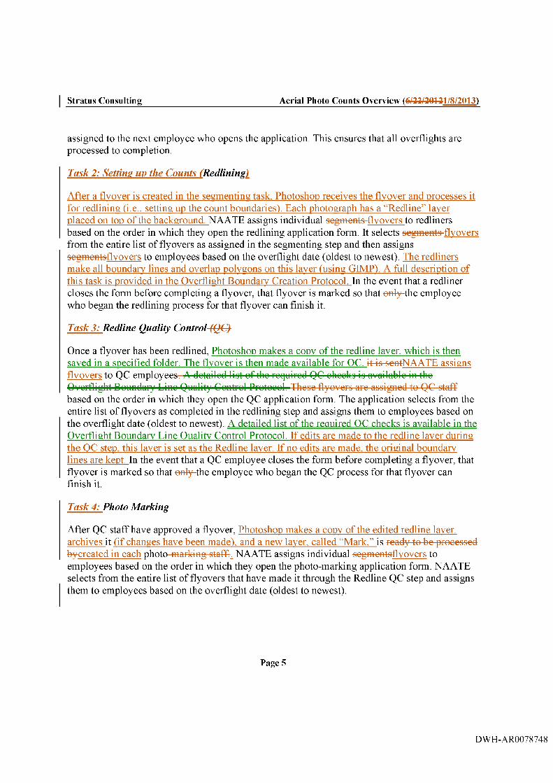
Task 2: Settine uy the Counts (Redlinins)
After a flyover is created in the segmenting task. Photoshop receives the flyover and processes it for redlining (i.e.. setting up the count boundaries). Each photograph has a “Redline” layer placed on top of the background. NAATE assigns individual segments flyovers to redliners based on the order in which they open the redlining application form. It selects segments flyovers from the entire list of flyovers as assigned in the segmenting step and then assigns segmentsflyovers to employees based on the overflight date (oldest to newest). The redliners make all boundary lines and overlap polygons on this layer (using GIMP). A full description of this task is provided in the Overflight Boundary Creation Protocol. In the event that a redliner closes the form before completing a flyover, that flyover is marked so that only the employee who began the redlining process for that flyover can finish it.
Task 3: Redline Quality Control-(Q€}
Once a flyover has been redlined, Photoshop makes a copy of the redline laver. which is then saved in a specified folder. The flyover is then made available for OC. it is sentNAATE assigns flyovers to QC employees. A detailed list of the required QC checks is available in the Overflight Bonndar}^ Lino Quality Control Protocol. Those flyovers are assigned to QC staff based on the order in which they open the QC application form. The application selects from the entire list of flyovers as completed in the redlining step and assigns them to employees based on the overflight date (oldest to newest). A detailed list of the required OC checks is available in the Overflight Boundary Line Quality Control Protocol. If edits are made to the redline laver during the QC step, this laver is set as the Redline laver. If no edits are made, the original boundary lines are kept. In the event that a QC employee closes the form before completing a flyover, that flyover is marked so that only the employee who began the QC process for that flyover can finish it.
Task 4: Photo Marking
After QC staff have approved a flyover, Photoshop makes a copy of the edited redline laver, archives it (if changes have been made), and a new laver. called “Mark.” is ready to be processed by-created in each photo marking staffs NAATE assigns individual segmentsflyovers to employees based on the order in which they open the photo-marking application form. NAATE selects from the entire list of flyovers that have made it through the Redline QC step and assigns them to employees based on the overflight date (oldest to newest).
Page 5
DWH-AR0078748

Stratus Consulting Aerial Photo Counts Ovei'view (6/22/20121/8/2013)
Photo-markers place color-coded dots on the photos, which correspond to the 23 location and recreation activity combinations that are being counted. A full description of this task is provided in the Overflight Picture Count Protocol. In the event that a photo-marking employee closes the form before completing a flyover, that flyover is marked so that only the employee who began the marking process for that flyover can finish it. Once the photo has been marked, it is ready for a second photo-marker to repeat the task. Photoshop archives the first counts layer, removes it from the Photoshop document (.psd). and creates a new counts laver for the next photo-marker to use. NAATE ensures that the employee who made the first set of marks on the photos in a flyover is barred from heingnot selected as the second photo-marker.
Photoshop
After all the steps described above are completed, Photoshop runs a script to prepare flyovers for the oubooquont stop. This is acoompliohod by running an indopondont script (“George”) that automatically runs the individual proceooing ocripto (described bolow),^ at various predefined time inton'alo.
Ready fo r Redline
Once a segmenter has assigned photos to a particular segment, thus creating a flyover, Photoshop receives the flyover and processes it for redlining. Each photograph has a “Redline” layer placed on top of the background; the redliners make all boundary lines and overlap polygons on this layer (using GIMP).
Ready fo r Redline QC
Initially, aPhotoohop makes a copy of the redline layer, which is then saved in a specified folder. The flyover io then made available for QC. If edits are made to the redline layer during the QC step, this layer is set as the Redline layer. If no edits were made, the original boundary lines are kept.
Ready fo r Marking
The approved redlined flyovers are then prepared for the marking step. Again, a copy of the edited redline layer is archived (if necessary), and a new layer, called “Counts,” is created in each photo. This is the layer in which photo markers place their color coded dots during the initial count.
3. Ever\ step for which the George script is responsible can also be run by process managers.
Page 6
DWH-AR0078749

Stratus Consulting Aerial Photo Counts Ovei'view (6/22/20121/8/2013)
Ready fo r Counting
After an emploveeof employees has marked every photo in a flyover, Photoshop counts the dots based on color. The CSS Extended version of Photoshop being used comes pre built with a recording tool that can count every instance of a selected color on a photo.
First, Photoshop disables the background and redline layers in order to prevent errors. Next, it runs through the pre-assigned list of 23 location/activity colors by searching for the unique RGB (red/green/blue) values and records the number of dots present in each category in the database.
The count for each photo is then recorded into the database. Next, the George script checks if the photo requires any additional total counts. If so. it archives, aggregated across all 23 locations/activities, are subjected to one of the following two reconciliation rules, based on the magnitude of the first counts layer, removes it from ;
a , If the .psd file, and creates a newaverage of the two counts laver for the nextis less thanor equal to 20. the two counts cannot differ bv more than 2
b. If the average of the two counts is greater than 20. the difference of the two counts cannot exceed 10% of the average.
If the two counts do not satisfy the applicable reconciliation rule from above, the photo is queued for a third photo-mark. After a third count is obtained, the photo marker to use, is marked as “complete” and the third count is recorded in the database. The average of the two closest counts for any photo is recorded in the database as the final reconciled count. In the case of three counts where one count is equally close to the other two counts, the average of all three counts is used. For example, counts of 2, 6, and 4 would be averaged because 4 is equally close to 2 and 6.
Once a photo has been processed an archived through the photo-marking task. Photoshop archives the .psd file is created by stripping out the background picture laver (this is done to minimize storage space), and-aleaving the redline layer and all counts layers are-in one compiled into one file. A backup copy of each layer is maintained in the corresponding folder. At any point, a .psd file can be easily recompiled so that data can be double checked.reviewed.
Task 5: Flyover Samplins Disyosition
Once counting is complete, photos are exported bv a process manager and grouped bv flyover and mark iteration into portable document format (.pdf) for a final sampling disposition review. After the export is complete. NAATE assigns flyovers to OC staff for review of the missing photos, overlap areas, and coverage selections for processed flyovers. A full description of this task is provided in the Flyover Sampling Disposition Oualitv Control Protocol. If any changes
Page 7
DWH-AR0078750

Stratus Consulting Aerial Photo Counts Ovei'view (6/22/20121/8/2013)
are made based on this review, the flyover is sent to a new reviewer who will verify the changes or make updates and send the flyover to a new reviewer.
Task 6: Flyover Oualitv Control (10% Checks)
After all flyovers are complete for a sampled month. 10% of flyovers are sampled bv a process manager for a final review. NAATE assigns OC staff flyovers with two marked documents (or three, if reconciliation required a third count). This OC task confirms that (1) the correct photos were selected for the flyover, and (2) the photos were redlined based on reference documents and overlap areas were correctly drawn. A full description of this task is provided in the Flyover Quality Control Protocol. If any errors were made, staff check to see if the count was affected. If the count was not affected, no changes are made. However, if the count was affected, then the psd is updated, an adjustment is made to the total count in the database, and the flyover is assigned to another reviewer for verification.
Once all flyovers in a sampled group are complete, the aggregate change in counts is compared to the total count for the sample. If this change exceeds 1% of the total count, then a new sample is drawn with replacement and the review is conducted on the new sample (excluding previously sampled flyovers).
Page 8
DWH-AR0078751

MS Canyon 252 GNU Image Manipulation Program
Software Tutorial
Overview
The GNU Image Manipulation Program (GIMP) is an image processing program used to automate components of the overflight photo process. For the current project, GIMP establishesis used to draw boundary lines-and^ areas of photo overlap,, and marks, in defined colors^ to designate different recreation typesrlocations and activities of beach users. Specific instructions regarding protocol and techniques to accomplish these tasks are included in a separate document' located in the relevant directory.
This guide introduces the software and its unique functions that you are likely to use. It includes the location of tools in the menus and specific functions or instructions that you may need to ensure that you are using the tools correctly. To open the software, locate the GIMP 2 icon on your desktop.
l^S ee the attachedOverflight Boundary Creation Protocol, the Overflight Boundary Line Quality Control Protocol, the Overflight Boundaiy^ Creation Protocol, and the Overflight Picture Counts Protocol.
DWH-AR0078752

Stratus Consulting -GNU In
Windows
GIMP opens in five separate windows: Main, Palettes, Toolbox, Layers, and Palette Editor windows. These are the only windows that you will need to use. These windows can be closed and reopened.
File E d it S e le c t VieiN I m a g e L a y e r C o lo rs l o o l s F i l te r s W in d o w s H elp
P a le ttes 0Beach • Fishing (I)
B each ■ G eneral (1)
B each - U nsure (I)
□ O th e r_ R e c _ A n e a - F ish in g ( l )
O i;h e r_ R e c _ A re a - G e n e ra l (1)
I I O th e r_ R e c _ A r e a - U n su re (1)
P ie rs_ Je i:tie s • F ish in g (1)
P ie rs_ Je i:tie s • G e n e ra l (1)
P ie rs_ Je i:tie s - U n su re (1)
W a te r ■ C a n o e o r K a y a k (1)
W a te r - F ish in g ( l )
I I W a te r - G e n e ra l [1)
W a te r - J e t S k ie rs (1)
I I W a te r - M o to rb o a ts (1)
W a te r - N u m b e r oF C a n o e s a n d Kay<
W a te r - N u m b e r oF J e t S k is (1)
I I W a te r - N u m b e r oF M o to rb o a ts (1)
W a te r - N u m b e r oF O th e r B o a ts (1)
W a te r - N u m b e r oF S a i lb o a ts (1)
W a te r - P a ra sa ilin g (1)
I I W a te r - S a i lb o a te rs (L)
I I W a te r - S u rf in g o r B o a rd sp o r ts ( l )
W a te r - U n su re (1)
L-ayers
N orm a
O p a c ity : laa.D
P a le tte Editor
Untitled C olum ns: 1
P a le tte Editor ( re a d only) 0B each • G eneral
Er3Sr05 x55}
Spacing:
Clicking the “x” in the Toolbox window will close GIMP. Clicking the “x” in any other window will close only that window.
Page 2
DWH-AR0078753

Stratus Consulting -GNU In
If you accidentally close a window or need to reopen a window for any reason, you can locate these tools in the “Windows > Dockable Dialogues” drop-down menu at the top of the Main window.
Recently Closed Docks 3qOQ
§ A ug032010_7664,psd-4,0
Toolbox:
Palette Editor
I Tool Options
I D evice 5ta:us
Q Layers
■ Channels
I Elths5 5 Colorniap
Histogram
L.'j Selection Editor
Navigation
^ Undo History
t ) Pointer
■<1 Sample F o n ts
Li Colors
^ Brushes
Patterns
y Gradients
Open the palettes
Pf ss FJ /brfTjpfB hep□ Buffers
^ Im ages
® Dooument History
1 3 lem pldtes
1 Tools
Error Console
Page 3
DWH-AR0078754

Stratus Consulting -GNU In
M o d e ; N o tm a l
O p a c i ty : 100.0
R e d lin e
Background
Layers
The layers feature makes it possible to create drawings over an image without altering it. Editing a selected layer does not affect any other layer within the photo. Layers are used in GIMP to differentiate the Aerial Photo Counts tasks being performed. Care should be taken to ensure that you are only editing in the layer that corresponds to the task to which you are assigned. The default layers that you will encounter can be seen in the Layers window, which is illustrated here.
Background Layer: Task 1
The Background Layer contains the photo that will be used as a reference for the task. Do not edit in this layer.
Redline Layer: Task 2
The Redline Layer allows you to draw red lines, overlap polygons, and segment boundary polygons.
Redline Quality Control (QC) Layer: Task 3
The Redline QC Layer will appear as the Redline Layer. However, it allows you to edit redlines and overlap polygons. When you are done, you will mark the file “edited” and the new laver will be archived.
CountsPhoto Markins Layer: Task 4
All recreation counts are marked on the Counts“Mark” Layer.
Opacity
The opacity slider is used to make a layer transparent. Slide this to 50% for the “Redline” Layer and 100% for the “CountsMark” Layer.
Viewing/Hiding Layers
Toggle the eye symbol to make a layer visible or invisible. The chain icon indicates that a layer is locked. Ensure that all layers are visible when you save a document. The “Mode” selection should be set to “normal” at all times.
Page 4
DWH-AR0078755

Stratus Consulting -GNU In
Color Palette
The Palettes window is loaded in your copy of GIMP with predefined colors for recreational locations. These colors are designated with a specific RGB (red green blue) color value that will be counted automatically at a later date. It is extremely important that you accustom yourself to using the exact designated color from the palette.
Setting the Correct Counts Color
There are two steps to ensure that the right color is selected for the activity or line that you are going to mark. First, single click on the recreation type you will be counting in the Palettes window (see sample screen shown here). The second step is to locate the Palette Editor window.
jpalettef— A
□
n□n□□□n
□
□
B e a c h ■ F ish in g (1)
B e a c h - i j e n e r a l (1)
B e a c h ■ U n su re (1)
O i:h e r_ R e c _ A re a - F ish in g (1)
O th e r_ R e c _ A re a - G e n e ra l (1)
O th e r_ R e c _ A re a - U n su re (1)
P ie rs_ Je ti:ie s ■ F ish in g (1)
Piers_Jei;i:ies - G e n e ra l (1)
Piers_Jei:i:ies ■ U n su re (1)
■Aiater ■ C a n o e o r K a y a k (1)
•Aiater - F ish in g (1)
■A'acer - G e n e ra l (1)
•Aiater ■ J e t S k ie rs (1)
l /J a te r ■ M o to rb o a ts (1)
•Aiater ■ N u m b e r oF C a n o e s a n d K a y a k s (1)
lA iater ■ N u m b e r oF J e t S k is (1)
•Aiater - N u m b e r oF M o to rb o a ts ( I )
•A iater - N u m b e r oF O th e r B o a ts (1)
•Aiater ■ N u m b e r oF S a ilb o a ts (1)
•Aiater - P a ra sa ilin g (1)
•Aiater ■ S a i lb o a te rs (1)
•Aiater - SurFing o r B o a rd sp o rts (1)
•Aiater - U n su re (1)
Page 5
DWH-AR0078756

Stratus Consulting -GNU In
P a le tte Editor
Pale tte Editor
B e a c h - G e n e r a l
Palette Editor
Double-clicking on a palette color will open the Palette Editor window. Inside there will he a single rectangular box that will update with the color of the recreation location that has been selected in the Palettes window.
Selecting the Color
After clicking the recreation type in the Palettes window, the Palette Editor window will automatically update with the name of the palette and the color in a single rectangle, m s box must be clicked prior to editing to ensure that the color is being used. At the bottom of the window, there is a column box that changes the number of colors in the palette. This should always be set to “Columns: 1.” If it is not set this way, an incorrect color could be applied.
Toolbox
0
U n t i t l ed C o l u m n s ;
The Toolbox is used to select the Pencil, which is used to draw lines and dots; the Paintbucket, which is used to fdl overlap polygons; and the Eraser tool, which is used to correct mistakes. The Toolbox also shows the color of the Painting tool that is currently selected. After selecting a color in the Palettes window, check to ensure that the color in the Toolbox matches the color in the Palette Editor window.
%
Pencil
The Pencil is defaulted to make a single dot when clicked; it will not click and drag. The size of the dot is chosen from the preselected options located in the Brushes window to allow for QC at later steps. When using the Pencil, you must select the small-sized dot from the Brushes window.
Eraser Tool
The Eraser tool can be used to correct small mistakes. When using the eraser, select the largesized dot in the Brushes window. When the Eraser tool is used, you must take care that all of the color you are erasing is gone. The preferred method of correcting a mistake is to use the Undo function, although this is not always possible.
Page 6
DWH-AR0078757

Stratus Consulting -GNU In
Paintbucket
Once the Pencil tool has been used to create a multi-sided, closed polygon, the Paintbucket can be used to fill the polygon. This is used to create an overlap polygon
Foreground Color
The two boxes of color in the Toolbox contain possible tool colors. The box in the foreground (top left) signals which color is currently selected through the Palettes and Palette Editor windows.
Background Color
GIMP also has the option of using a background color to switch quickly between colors. This is the rectangular box below the foreground color, which can be brought to the foreground by clicking on the arrow symbol. This is most helpful for redliners who use only two colors. However, the colors used in these boxes must always be selected through the Palettes and Palette Editor windows to ensure that the proper colors are used.
Brushes
The Brushes window provides two preselected size options to be used with tools from the Toolbox. Simply click on a brush and a box will appear around your selection.
Larger Brush
The larger brush should be used with the Eraser tool to correct mistakes.
Smaller Brush
BrushesEr3ser(SS 55}
0
A
—
S p a c in g ; 20,0 *
The smaller brush should be used with the Pencil tool to create lines.
Page 7
DWH-AR0078758

Stratus Consulting -GNU In
Docking Dialogue Boxes
All the dialogue boxes described above can be combined into one simplified window. This should be the default appearance of your Toolbox window. Should your windows become undocked and you need to recreate this appearance, follow these steps:
Click on the (in this case Palette Editor) and drag it into the Toolbox.
Editor ( r e a d only)
ypc/ cjn dvp (£3/c>ghefB
U n title d C o lu m n s:
title of the window
I P a le tte Editor
P a le tte Editor
Page 8
DWH-AR0078759

Stratus Consulting -GNU In
After repeating the drag-and-drop process with all the windows, your screen should look like this:
Layer'sM ode l N o im ^ l P a le t t e s
O p a c ity 1 B e a c h ■ F ish in g [1)
B e a c h ■ G e n e ra l (1)
B e a c h ■ U n su re (1)
O c h e r_ R e c _ A re a - F ish in g (1)
O th e r_ R e c _ A re a ■ G e n e ra l (1)
O c h e r_ R e c _ A re a ■ U n su re (1)
P ie r s _ J e t t ie s - F ish in g (1)
P ie r s _ J e t t ie s ■ G e n e ra l (1)
P ie r s _ J e t t ie s ■ U n su re (1)
W a te r - C a n o e o r K a y a k (1)
W a te r ■ F ish in g (1)
W a te r - G e n e ra l (1)
W a te r - J e t S k ie rs (1)
W a te r - M o to rb o a ts (1)
W a te r - N u m b e r o f C a n o e s a n d K a y a k s (1)
W a te r - N u m b e r o f J e t S k is (1)
W a te r - N u m b e r o f M o to tb o a ts (1)
W a te r - N u m b e r o f O th e r B o a ts ( I J
W a te r - N u m b e r o f S a i lb o a ts (1)
W a te r - P a ra sa il in g (1)
W a te r - S a i lb o a te rs (1)
W a te r - S u rfin g o r B o a rd sp o r ts (1)
W a te r - U n su re (1)
Lock: Q
R ed lin e
Backqt'ound
B rushesf r A f e r |5 F 5 5 }
Spacing
P -a le tte E ditor' ( r e a d o n ly ) Q
B e a c h - G e n e ra
Sfl.. .t;, .r.. .T, .n. .t; , iT; , if. Tf
U ntitled C o lu m n s : 1
It is recommended that you leave the Palettes window separate for ease of color selection during the drawing tasks, especially during marking.
Page 9
DWH-AR0078760

Stratus Consulting -GNU In
Zooming and Scrolling
You can zoom by holding “Ctrl” and scrolling the mouse wheel up to zoom in or down to zoom out. The mouse wheel will also allow you to pan across the photo if you “hold-click” (click then hold) the scroll (center) button and move the mouse.
Specific zoom levels can be selected using the View > Zoom drop-down menu in the Main window. Fit Image in Window will zoom to the full extent of the photo in your Main window.
Note: Holding “Ctrl” also enables the Color Picker tool, which will change your paintbrush color. Ensure that you do not left or right click when “Ctrl” is depressed. I f you do click, you must reselect the recreation color.
Drawing
Lines
*A u B 032010_7664 .p sd -4 .0 (RGB, 3 layers) 5 6 1 6 x 3 7 4 4 - GIMP
File Edit Select
0|O ...........Image Layer Colors lools
Q New View
v* Dot For Dot
Shrink Wrap
Fullscreen
^ Navigation Window
Display Riters...
Show Selection
v* Show Layer Boundary
Show Guides
Show Grid
v* Show Sample Points
Snap to Guides
Snap to Grid
Snap to Canvas Edges
Snap to Active Path
Q Padding Color
v* Show Menubar
v* Show Rulers
V* Show Scrollbars
Show Statusbar
Filters Windows Help
. ............................
Revert Zoom (25%)
ZooiTi Out
Zoom In
4* Fit Image In Window
6^ Fill Window
16 :1 (1 6 0 0 % )
8 :1 (8GG7o)
4 :1 (4GG7o)
2 ;1 (2GG7o)
i ; l (lG G 7o)
1 :2 (5 G 7 0
1 ;1 (2 5 7 o )
1 :8 (1 2 ,5 7 o )
1 :1 6 (6 ,2 5 7 o )
Other(217o),,,
Draw lines by single clicking the first point and then pressing and holding “shift” and clicking once for each new point of the line. After clicking the last desired point, release the shift key. If you are using the Paintbucket tool, ensure that the lines of the polygon that you are drawing are closed (i.e., all vertices touching) or cross the edges of the photo. This ensures that the Paintbucket tool will fill only the polygon you have drawn with color.
Dots
SingleA single click to createcreates a dot on top of a recreator. Ensure that every dot you create is not touching any other dot. If vour dot appears as a line rather than a circle, let a senior team member know and they will update vour settings.
Erasing
The Eraser tool can be used to correct mistakes; however, you should use Undo if the mistake is recent. When deleting a line or dot, you must erase the marks completely from the layer so that they are not counted in a later step.
Page 10
DWH-AR0078761

Stratus Consulting -GNU In
Undo
GIMP allows you to undo repeatedly to correct mistakes. Use this function to ensure that an entire erroneous dot or line is cleared. Remember that when undoing a line, you must undo the initial dot that you created to begin the line, as well as all subsequent vertices.
Paintbucket
Use the Paintbucket after drawing a closed overlap polygon. Click once inside the polygon to fill it with uniform color. Use this tool during either of the redlining steps to create yellow overlap polygons.
Saving
Your work is important. Be sure to save frequently and upon completion of your work. GIMP will ask if you want to save changes when closing the program or a photo. Ensure that you save the photo when you are done placing red lines, overlap polygons, or dots.
Shortcuts
For easier maneuvering through GIMP, use the shortcuts listed below. Simply type the letter or sequence and the desired tool will be selected or action taken.
Command KeySelect Layer L
Eraser E
Pencil PPaintbucket BSwap Colors A
Redo CTRL Y
Undo CTRLZFullscreen F l l
Page 11
DWH-AR0078762

MS Canyon 252 Overflight Segment Assignment Protocol
General
► Record all notes in your project notebook► Send all emails pertaining to this project through your MS Canyon 252 email account► Use your MS Canyon 252 email account for emails pertaining to this project only.
Stratus Consulting Points of Contact
► Administrative/scheduling; Kevin Lazar► Data process manager: Justin Steim
Task 1: Segment Assignment (Segmenting)
Your goal in segment assignmentThe purpose of this task is to assign overflight photos from a particular flight date to their corresponding shoreline segments, based on the coordinates of these shoreline segments.^ Since photos must beare sequential in time, we need to include all the photos available between the first and last photo. To do this, you will compare thosethe coordinates of a segment to the coordinates of multiple image files by using the “SegmentingSegment Photo Assignment” application. Follow the steps below.
DWH-AR0078763

Stratus Consulting Overflight Segment Assignment Protocol (6/22/20121/8/2013)
^Segm enting
S a m p le A rea : N G F light D ate: 1 2 /3 /2 0 1 0
- n i i x l
SEGMENT PH OTO ASSIGNMENT
Flight ID: 4 1 5S e g m e n t G im p P r o t o c o l P r o t o c o l
O pen Photo
-U n a ss ig n e d S e g m e n ts - - Photo A ss ignm en t-
P h o to N um ber Photo NumberNG 63NG 68 30.2998632 89.2879836NG 73NG 78 30,2993242 89.2859377
30.3001208 89.2771038NG 88NG 93 30.3807805 89.2748165NG 98NG 1G 3 30.30 2603 89.2725807N G 1 0 8
30.30399 7 89.2637782NG 113NG 118
30,306742 89.2547607NG 123N G 1 2 8 30.3084728 89.2478485N G 1 3 3
30,3089776 89.2456408NG 138NG 148
30.3094316 89.2431797NG 148N G 1 5 3 30.310G791 89.2409295N G 1 6 3N G 1 7 8 30.3107939 89.23875NG 183
30.3139339 89.2302064NG 188NG 193 30,3146887 88.22803N G 2 0 3N G 2 1 3 30.3155043 89.2258275NG 218
30,3162686 89.2236758NG 223N G 2 2 8 30.3170645 221523N G 2 3 3NG 238 30.3178804 89.21936 6NG 243
C o nf i rm A s s i g n m e n tG u e s s A s s i g n m e n t
<N ot Y e t Specified>
1. Open the application on your desktop and click “Segment.” The segment form will open and you will see an automatically assigned Flight ID, representing an overflight from a specific date.
Flight ID: 4 1 5
2. To the left is a column titled “Unassigned Segments.” This is the list of the segments that must have photos assigned to them.
Page 2
DWH-AR0078764

Stratus Consulting Overflight Segment Assignment Protocol (6/22/20121/8/2013)
3. To begin the assignment process, first open the reference PDF by clicking the “PDF” button at the bottom left of your screen. This will open a reference document showing photos of the entirea segment group to which you need to assign photos.
Next, open the Google Earth file showing your segment group by pressing the “KMZ” button, located next to the “PDF” button. This opens a Google Earth map showing the location of every shoreline segment in the North or South Gulf region. It also opens a list of global positioning system (GPS) waypoints, which show up as dots on your Google Earth map. Each of these dots represents the location, by GPS coordinates, of a photo, and has a corresponding file name. It is possible for a GPS coordinate to be dropped by the GPS unit during flight; double check all missing therefore, it is possible for photos to exist in the photo directorvr even if the waypoint is missing in the KMZ file.
Under the “Photo Assignment” box, you will see a subset titled “Available.” This is a list of all of the photos that correspond to the Flight ID of your assignment. The box on the right, titled “Assigned,” will show the photos that you have identified as belonging to a particular segment.
Page 3
DWH-AR0078765

Stratus Consulting Overflight Segment Assignment Protocol (6/22/20121/8/2013)
1 ^ 1Photo Number let Ion ^ Photo Number lah Ion
□ pen 2 30.2998G32 -89.287983G 1 Open 1152 1 30.3871G72 -88.94626941
□ pen ] 3 30.2393242 -89.2859377 1 Open |j 153 1 30.3873537 -88.9439161
□ pen ] 7 30.3001 208 -89.2771038 [ Open ] i 154 130.387489 ■88.94152991
□ pen J 8 3G.3GG78G5 -89.2748165 f Open ]j 155 1 30.3876517 -88.9391811 [
□ pen J 9 30.3012G03 -89.2725807 [ Open J| 158 1 30.3878143 -88.93684081
□ pen J 13 30.3039917 -89.2637782 [ Open ]|157 1 30.3878788 -88.9344961 |
□ pen j 17 30.306742 -89.2547607 [ Open ] i 158 i 30.388103 -88.83220151
□ pen j 20 30.3084728 -89.2479495 1 Open ]j 159 1 30.3882188 -88.9298744 1
□ pen J 21 30.3089776 -89.2456408 [ Open ] i 160 1 30.3883137 -88.927523 |
□ pen j 22 30.3084316 -89.2431797
□ pen J 23 30.31 00791 -89.2409295
□ pen j 24 30.31 07939 -89.238751
□ pen J 28 30.31 39339 -89.2302064
□ pen J 29 30.31 46887 -89.228031
□ pen j 30 30.31 55043 -89.2258275
□ pen J 31 30.31 G2G96 -89.2236759
□ pen J 32 30.31 70G45 -89.221523
□ pen j 33 30.31 78804 -89.2193616 -
<
To begin assigning photos, first select a segment from the “Unassigned Segments” column. Then, press the “Guess Assignment” button. This will load the “Assigned” box with the computer’s best guess of photos that fall within the segment you have chosen, based on the latitude and longitude of each photo.
G uess Assignment
Next, check that each photo that the computer has assigned to the segment has been properly chosen. To the left of each Photo Number is a button titled “Open.” Pressing this button will open the image in Windows Picture and Fax Viewer, which allows you to scroll back and forth quickly between photos. By comparing the assigned images to the Reference Segment PDFreference segment document you will be able to tell which photos should be assigned to a particular segment.
Page 4
DWH-AR0078766

Stratus Consulting Overflight Segment Assignment Protocol (6/22/20121/8/2013)
NA ssig n ed
O p en 152 3 0 .3 8 7 1 6 7 2 -8 8 .9 4 6 2 6 9 4
□ p en 153 3 0 .3 8 7 3 5 3 7 -88.9439161
□ p en 154 3 0 .3 8 7 4 8 8 -3 8 .9 4 1 5 2 9 9
□ p en 155 3 0 .3 8 7 6 5 1 7 -88.9381811
□ p en 15G 3 0 .3 8 7 8 1 4 3 -8 8 .9 3 6 8 4 0 8
□ p en 157 3 0 .3 8 7 9 7 8 8 -88.9344961
□ p en 158 3 0 .3 8 8 1 0 3 -8 8 .9 3 2 2 0 1 5
□ p en 159 3 0 .3 8 8 2 1 6 6 -8 8 .9 2 9 3 7 4 4
□ p en 160 3 0 .3 3 3 3 1 3 7 -8 8 .927523
You should first locate the pictures showing the beginning and ending boundary of your segment. Every photo that falls between these two points should be included in your photo assignment for that segment, including redundant or blurry photos, as well as photos of the interior of the plane, etc. Unnecessary or redundant photos will be removed at a later step.
It is possible that, in some cases, photos of the beginning or ending boundary of your segment will not have been captured during the overflight process. You should proceed with the photo assignment task to the best of your ability regardless. Select the necessary data from the “Missing Photos” dropdown box. If no photos are missing, select the default “No photos are missing” choice.If the photo is missing the beginning boundary only, select “Photos are missing from the beginning.” If the flyover is missing the ending boundary only, select “Photos are missing from the end.” If both boundaries are missing (the beginning and ending boundary), then select “Photos are missing from the beginning and the end” from the menu. If both boundaries are shown (i.e.. any part of the beginning or ending boundary), select “No photos are missing.”
M iss in g P h o to s : l<Mol: Yel: Specified>
9. The computer is coded to add extra “buffer” images to its segment assignment guess. It is therefore likely that you will have to remove images from the “Assigned” box. To do so, double-click on the photo name, which will move the photo from the “Assigned” box to the “Available” box. Likewise, if you need to add photos to a segment, simply doubleclick on the photo name to move it to the “Assigned” box.
Note: If at any point it is necessary to search through the photo directory to identify the proper photos that correspond to a given segment, click the “Open Photo Directory”
Page 5
DWH-AR0078767

Stratus Consulting Overflight Segment Assignment Protocol (6/22/20121/8/2013)
button. This will allow you to navigate the corresponding image folder and identify photos that should he assigned to the segment that you are working on.
11 .
O p en P h o to D irectorv
When you have finished assigning all the photos for a particular shoreline segment, press the “Confirm Assignment” button. The computer will ask you if you have doublechecked your work. Clicking “Yes” will finalize the photo assignment for that segment, remove it from the “Unassigned Segments” list, and send it to the next step in the process.
Confirm Assignment
Note -. Before pressing the “Confirm Assignment” button, please double-check all of your work. All of your photo assignments will undergo quality control at a later step. Please remember that by working carefully, you reduce the workload for others at future steps.
Repeat steps 6 through 9 for every unassigned segment in the “Unassigned Segments” column.
12. The “Segment Protocol” and “Gimp Protocol” buttons at the top of the form will open both protocol documents as a resource for questions and step-by-step instructions.
i1
Page 6
DWH-AR0078768

MS Canyon 252 Overflight Bonndary Creation Protoeol
General
► Record all notes in your project notebook► Send all emails pertaining to this project through your MS Canyon 252 email account► Use your MS Canyon 252 email account for emails pertaining to this project only^
>■-------You are responsible for providing the Aerial Photo Counts Technician with advancednotice if you are short on work.
Stratus Consulting Points of Contact
► Administrative/scheduling: Kevin Lazar► Data process manager: Justin Steim
Task 2: Setting up the Counts (Redlining)
This task uses GNU Image Manipulation Program (GIMP) software. For a detailed summary o f how to operate GIMP successfully, see the GNU Image Manipulation Program Software Tutorial.
The purpose of this task is to create consistently delineated boundaries for each flyover in which recreators can be counted. You will inspect the photos corresponding to your group of segments.for each flyover assigned in the Segmenting step (Task 1), and create redlined inland boundary images in GIMP for each sesm entflvover.
1. Open the application on your desktop and click Redline. A new window, the Redlineform, will open. You will see a Flyover ID and a corresponding series of photos. Open the first two photos from the segmentflyover you have been assigned to redline in GIMP. Note that GIMP will open each photo in a separate window.
Opening more than three photos simultaneously will cause computer slowdown. By comparing photos side-by-side, you will be able to draw interior boundary lines, or redlines, as well as yellow overlap polygons.
DWH-AR0078769

Stratus Consulting Overflight Boundary Creation Protocol (6/22/20121/8/2013)
Redlining ____R E D U N E E N T R Y
Flyover ID: 23145 Segm ent: NG 57Flight Date: 4 /2 /2011
M iss ing P h o b S la iu s ;
R e d l in e I G im p P r o to c o l P r o to c o l i
I N o p h o to s a re m issing
1 P h o to N a m e C o v e r a g e O v er la p R e d lin e S ta tu s C om m en t
I O p e n 1 A p r_ 0 2 _ 2 0 1 1 _ 2 3 0 1 | N o C o v e r a g e S e le c te d V 1 N o O v e r la p S e le c te d V N o t Y e t R e d lin e d
i[ O p e n j| A p r_ 0 2 _ 2 0 1 1 _ 2 3 0 2 | N o C o v e r a g e S e le c te d V 1 N o O v e r la p S e le c te d - N o t Y e t R e d lin e d V |
i| O p e n ]i A p r_ 0 2 _ 2 0 1 1 _ 2 3 0 8 | N o C o v e r a g e S e le c te d V 1 N o O v e r la p S e le c te d - N o t Y e t R e d lin e d - 1
j[ O p e n ]| A p r _ 0 2 _ 2 0 1 1 _ 2 3 0 7 1 N o C o v e r a g e S e le c te d V 1 N o O v e r la p S e le c te d - N o t Y e t R e d lin e d - 1
!| O p e n ]| A p r_ 0 2 _ 2 0 1 1 _ 2 3 0 G j N o C o v e r a g e S e le c te d V 1 N o O v e r la p S e le c te d V N o t Y e t R e d lin e d - 1
i [ O p e n J i A p r _ 0 2 _ 2 0 1 1 _ 2 3 0 5 1 N o C o v e r a g e S e le c te d V 1 N o O v e r la p S e le c te d - N o t Y e t R e d lin e d V |
i[ O p e n J | A p r_ 0 2 _ 2 0 1 1 _ 2 3 0 4 | N o C o v e r a g e S e le c te d V 1 N o O v e r la p S e le c te d - N o t Y e t R e d lin e d - 1
I O p e n JI A p r_ 0 2 _ 2 0 1 1 _ 2 3 0 3 j N o C o v e r a g e S e le c te d V 1 N o O v e r la p S e le c te d - N o t Y e t R e d lin e d - 1
Click the button “Open Reference Document,” marked with a PDF icon. This document is the guide that you will follow as closely as possible as you create your redlined photos.
Look at the reference segment to see where the beginning and ending boundary red lines have been drawn. Draw these same beginning and ending red boundary lines on the first and last pictures in the segment sequence. This is done using the pencil tool in GIMP with the small brush option. To draw a straight line, click once to set a starting point, hold the “shift” key, and click again to draw a line connecting the two points.
Ensure that while you are redlining, every mark you make is made in the corresponding Redline layer in GIMP, which is the default layer. You can check this by looking at the Layers tab in GIMP. You should never need to select a layer other than the Redline layer. The shortcut, the L key, can be used to ensure that you are working in the Redline layer.
ToolboK H
B ru sh es 0
1 '
S p a c in g ; - 20.0 Z
P a l e t t e E d i to r ( r e a d o n ly ) Q
B e a c h - U n s i j r e
U ntitled Columnsi 1
Page 2
DWH-AR0078770

Stratus Consulting Overflight Boundary Creation Protocol (6/22/20121/8/2013)
5.
Note: The Opacity slider in the Layers tab is used to make the redlines and overlap polygons more or less see- through. In certain cases, such as determining whether or not an overlap polygon has covered a recreator, you may wish to change the opacity setting. To do so, simply slide the bar up or down depending on your desired opacity level.
While following the Reference Segment PDF document, drawDraw interior boundaries on each photo in the shoreline segment based on the reference segment document. It is critical that you copy the interior boundary lines that you see in the reference segmentdocument exactl gaps in the red interior boundary line that you draw.
LaversN otm al
O p a c i ty !
R adlina
B ac k g ro u n d
Note that there should be no
Next, draw an overlap polygon (if applicable). This will mark thean area that should not be counted in a later step because it was already counted in a previous picture.
To find the overlap, compare two sequential photos side-by-side and note whether there is any area that is covered in both photos. That area should be marked as “overlap” so that it is not counted in both photos. Likewise, any recreators that appear in more than one photo should be covered by this yellow polygon to ensure that they are not doublecounted.
To mark an area as covered by overlap, draw a yellow overlap polygon. Select the yellow overlap color from the Palettes menu. By holding the “shift” key and clicking to draw lines, draw a multi-sided polygon that intersects the interior boundary line at two points. Ensure that the polygon follows the photo overlap line exactly, covers any applicable recreators, and extends to the bottom of the photo. Then, select the Paintbucket option and click once inside the polygon you have just created. This will fill the overlap area with yellow color, marking it as outside the area to be counted in a later step. Finally, select “Overlaps Previous Photo” in the Overlap dropdown box.
If there is no overlap between photos, select the dropdown in the Overlap column titled “Does not overlap with previous photo.” Please double-check before making this selection.
If you are redlining the first photo inqf the segment, there will be no overlap. In this case, select the option titled “Photo is first in series for segment” in your Overlap dropdown box.
O verlap
P h o to is first in se ries for seg m en t V
O v erlap s p rev ious pho to V
N o ov erlap with prev ious pho to V
O v erlap s p rev ious pho to V
O v erlap s p rev ious pho to V
N o O verlap S e le c te d V
Page 3
DWH-AR0078771

Stratus Consulting Overflight Boundary Creation Protocol (6/22/20121/8/2013)
If you are redlining the first photo in the segment, there will be no overlap. In this case, select the option titled “Photo is first in series for segment” in your Overlap dropdown box. However, if areas at the beginning a segment are not pictured, select “Photos are missing from the beginning only”; if areas at the end of a segment are not pictured, select “Photos are missing from the end only”; and if areas are missing at both the beginning and end, select “Photos arc missing from both the beginning and the end.”
C o v erag e
N o m issing a re a V
In land a re a m issing (b e a c h u s e rs possiblii excluded ) V
W a te r a re a m issing (sw im m ers possibly excluded ] V
In land a n d w ater a re a s m issing V
N o m issing a re a V
N o C o v e rag e S e le c te d V
Last, inspect the picture you are drawing boundary lines on and decide if there is sufficient coverage. This is to designate if part or all of an area designated for counting is not captured in the photo. If coverage is missing for any of the area categories (Beach Area, Water Area,Pier/Jetty Area, and Other Recreation Area), mark the appropriate combination of missing areas that apply. If the photo is nearly impossible to count due to darkness, select “Darkness” in the coverage drop down menu for that photo. If the photo is nearly impossible to count for some other reason such as blurry, foggy, extremely distant, or completely obscured by objects, select “Image obscured” from the dropdown menu. Each picture should include an area far enough out from the shoreline so that all likely swimmers are included. In other words, there should be a significant area of water at the bottom edge of each picture where no swimmers are found. If this is not the case, check the box labeled “Water area missing” in the Photo Coverage section. If there is no area missing, select the “No missing area” choice in the Coverage dropdown box.
Note: For segments that only include a pier, there is no reason to select “Inland area missing” or “Water area missing.” Since the pier represents a segment, a photo missing from the segment would be a case of “No overlap.”
If the overlap does not extend through the height of the beach or water, select “No overlap.”
If you have already selected the “No overlap” option, the coverage selection will not be dependent on the extent of the overlap.
Please take care in assigning photo data because all of your selections must undergo quality control (QC) at a later step.
Page 4
DWH-AR0078772

Stratus Consulting Overflight Boundary Creation Protocol (6/22/20121/8/2013)
When you are finished redlining a photo, save and close it. Then choose “Redlining Complete” in the Redline Status column. Repeat the redlining process for every photo in the segment.
R edline S ta tu s
R edlining C om plete V
R edlining C om plete V
R edlining C om plete V
R edlining C om plete V
N o Redlining: P h o to d o e s no t a p p e a r to b e of part of s eg m en t V
Not Y et R ed lined V
If a photo has been incorrectly assigned to your segment, meaning that it shows a shoreline area that falls outside of the segment you are redlining, select the dropdown box titled “No Redlining: Photo does not appear to be part of segment” in the Redline Status dropdown column. This step will be double-checked by the QC team. This button can also be checked if the photo is a complete duplicate of another photo and contains nothing but overlap, or if it shows only an image of the sky or interior of the aircraft.
When you have finished drawing boundary lines on every photo that corresponds to the segment, select “Confirm” in the main Redline form. All of your boundary lines will be reviewed by a QC team member who will either approve it for marking or send it back to you for further revisions.
Confirm
Note : Before pressing the “Confirm” button, please double-check all of your work. All of your boundary lines and overlap polygons, as well as assigned photo data, will undergo QC at a later step. Please remember that by working carefully, you reduce the workload for others at future steps.
The “Redline Protocol” and “Gimp Protocol” buttons at the top of the form will open both protocol documents as a resource for questions and step-by-step instructions.
1
1
Page 5
DWH-AR0078773

MS Canyon 252 Overflight Boundary Line Quality Control Protoeol
General
► Record all notes in your project notebook► Send all emails pertaining to this project through your MS Canyon 252 email account► Use your MS Canyon 252 email account for emails pertaining to this project only.
Stratus Consulting Points of Contact
► Administrative/Scheduling: Kevin Lazar► Data process manager: Justin Steim
Task 3: Redline Quality Control
This task uses GNU Image Manipulation Program (GIMP) software. For a detailed summary o f how to operate GIMP successfully, see the GNU Image Manipulation Program Software Tutorial.
General Responsibilities
>■-------Answer staff questions related to aerial photo counts. Follow up with a point of contactabove if necessary.
y -------Approve redlined segments and make required edits to redlined shoreline segments asneeded (see Approvals Protocol below). Replace and update reference segments as needed (based on photo coverage and quality).
►-------Give immediate feedback to redliners based on their performance.>■-------Complete tasks for process managers on an as needed basis.This process also requires knowledge o f the Overflight Segment Assignment a n d -^
Overflight Boundary Creation Protocols; review these protocols before starting this task and later as needed.
Approvals Protocol
Please refer to the protocol fo r “Task 2: Setting up the Counts (Redlining) ’’fo r details on how to create boundary lines and overlap polygons and the GNU Image Manipulation Program Software Tutorial fo r details on operating GIMP software.
DWH-AR0078774

Stratus Consulting Overflight Boundary Line Quality Control Protocol (6/22/20121/8/2013)
You will be assigned a group of shoreline segments from a particular set of overflightphotos. You will inspect the photos that correspond to your group of segments and edit “redlined” photos that have been completed by a team in the previous step.
This purpose of this task is to approve redlined flyovers and make required edits as needed. If necessary, provide constructive feedback to redliners based on their performance.
2 r l . _Open the application on your desktop and press Quality Control (QC). The Redliner QC Assignment formThe “Segment and Redline Quality Control” application will open and you will see a list of photos, all corresponding to a Flyover ID, flight date, and segment number. All of these photos should have red boundary lines drawn. The top half of the form will show you the history of the previous steps that the flyover has already been through. This will give you background on the segmen t should you need itflvover.
^ Q uality C ontrol
SEGM ENT A N D REDUNEUl IX
Q U A U TY CONTROL
Flyover ID: 22861 Flight Date: 8/31/2010 Segment: SG 286- Flyover and Photo Histoiy-----------------------
Timestamp Nam e Action Comment
stein N ew Flyover of S egm ent A dded to System i iG/14/2011 1 13 PM therbertmsc Segm enter U pdated Flyover Missing Photos Setting No photos a re missing
6/14 /2011 1 13 PM theibertm sc Photo A ssigned to Flyover
6 /14 /2011 1 :13PM therbertmsc Photo A ssigned to Flyover
6 /14 /2011 1 :13PM therbertmsc Photo A ssigned to Flyover
6 /14 /2011 1 :13PM therbertmsc Photo A ssigned to Flyover
6 /14 /2011 1 :13PM therbertmsc Flyover H as B een A ssigned Photos V
< >
Redline Status
I O pen { Aug_31_201Q_0Q11 No nissing a rea v i O verlaps previous photo ^ Redlining Complete
[ O pen ] A ug_31_2010_0010 No nissing a rea v | O verlaps previous photo Redlining Complete
[ O pen ] A ug_31_2010_0009 No nissing a rea v i O verlaps previous photo v Redlining Complete
[ O pen ] A ug_31_2010_0012 No nissing a rea v | Photo is first in series lor segm ent v j Redlining Complete
ConlitmRemoval
RedlineE dited? Comment
□ 1 □ 1
□ 1 □
□ 1 □□ 1 □
I N o photos are missing A d d P h o to ( s ] t o F ly o v e r
R e s e t S e g m e n t ( r e m o v e a ll p h o to s a n d a d d new )
R e tu rn to R e d l in e r
Open the first two photos from the segmentflyover you have been assigned to QC in
Page 2 IFlyover P h o to s -
P h o to N am e
□ pen M ar 22 2011 20 0 6
DWH-AR0078775

Stratus Consulting____________ Overflight Boundary Line Quality Control Protocol (6/22/2012178/2013)
GIMP by pressing the “Open” button.
Note that GIMP will open each photo in a separate window; opening more than twophotos at once will cause computer slowdown.
3t2. Click the button with the PDF icon. This will open the reference segment, the templatethat you will compare against the previously redlined photos as accurately as possible. document. This document shows where the redline boundaries should be drawn for a particular segment. Note that staff working on redline QC are responsible for notifying senior staff when changes to reference segments are needed, based on changes in segment conditions and/or improvements in photo coverage and quality. Clicking the KMZ icon will open the Google Earth file showing the segments in their corresponding groups and geographical locations. If you need to double-check the segment photo assignment, open the photo directory using the “Open Directory” button (the folder icon) to scan through each photo.
4t3. Quickly scanReview the photos in the segment flyover you are working on to determine if you are going to edit the segment or reset the flyover and send it back to the segmenting task (Task 1). return it to the redliner for editing, or edit (if necessarvl and approve the flyover yourself.
a The segment should only be returned to the redliner if numerous, time consumingedits are needed to ensure that the segmentThere may be cases when the photos included in the flyover are incorrect non-sequential. come from two or more unique sets of photos of the segment at different times, or need to be returned for segmenting for another reason. In these instances, you can choose to reset the flyover and send it back to the segmenting task (Task 1). Click “Reset Segment (remove all photos and add new).” This will undo all work on the flyover (i.e.. removes all photos and redlines) and open the Segmenting form. After you complete the segmenting step (as described in Task I), press the “Confirm” button and the segment will be sent back to the redlining step (Task 2). If you choose to reset the segment your review of the segment is complete. Otherwise continue to step 4b.
R e se t Segm ent (remove all photos and add new)
Page 3
DWH-AR0078776

Stratus Consulting Overflight Boundary Line Quality Control Protocol (6/22/20121/8/2013)
ftrb. The flyover should be returned to the redliner if numerous, time-consuming edits are needed to ensure that the flyover is properly prepared for the counting step (e.g., if the redliner forgot to add inland boundaries to a segment), press). Press the “Return to Redliner” button on your assignment form. This will prompt you to consider this decision carefully. Ensure to note issues in the comment boxes so that the redliner will know what to correct. If you choose to return the segment to a redliner. your review of this segment is complete. Otherwise, continue to step 4c.
Return to Redliner
If you choose to edit the segment, proceed to step 7.
brC. _If there are missing or unnecessary photos, there is an optionare options to either add or delete photos. If you need to do both, always delete the photos first before adding any photos. To delete a photo, the redlining status must be set toPhotos are deleted by selecting “No Redlining: Photo does not appear to be part of segment” by either the redliner or a previous Quality Controller. Then check the box “Confirm Removal” to delete the photo. If the redlining status is not correct, select “No Redlining” from the dropdownin the Redline Status drop down menuand the photo will go to another Quality Controller to confirm the removal after the flyover is confirmed. You. Once you have set this status, you will notice that the “Add Photo(s) to Flyover” button has been disabled. Only after another Quality Controller confirms your removal can another photo be added (if necessary).the removal of the photo can another photo be added (if necessary). If you have finished updating the status, continue to step 5. If you are confirming the deletion of a photo, the status must already be set to “No Redlining: Photo does not appear to be part of segment” in the redlining step or by another Quality Controller. You can choose to update the redline status (reject the deletion) or to click the box for “Confirm Removal.” After you have clicked the confirm removal box, you can select photos to add to the flyover if necessary.
R edline S ta tu sConfirnnR em oval
No Redlining: P h o to d o e s no t a p p e a r to b e of part of s eg m e n t v □If you need to add a photo, click the “Add Photo(s) to Flyover” button and the Segment Photo Assignment form will open.
Page 4
DWH-AR0078777

Stratus Consulting Overflight Boundary Line Quality Control Protocol (6/22/20121/8/2013)
^ S e g in e n t in g
S E G M E N T P H O T O A S S I G N M E N T
S a m p l e A r e a ; N G F lig h t ID: 3 6 5 F lig h t D a te : 3 / 2 5 / 2 0 1 1
Phob Assignmert—
Avalable
Open 11 30.2171237 •88.4105327
Open J 2 30 2163816 •88.4128133
□ pen 1 3 30.2160063 -88.4141021
Open 1, 4 30.21525C3 •00.4104470
Open J 5 . 30 2145409 -88.4187391
Open 1 G 30.213911 -88.4211G01
Open J 7 .30 2133092 •88.4235772
Open |, 8 30 2127443 -88.4260363
Open 1 9 30.2122374 -88.4285364
Open J 1 0 30 2117423 •88.4310364
Open i l l 130 2111473 -88.4335344
Open j, 12 30.2104292 •88.4358387
Open 1 13 ,30 209653 •88.4381027
Open j 14 30.2087881 -88.4403123
Open 1 15 302079203 •88.4425344
Open j; 16 .30 2071477 •88.4448324
Open 1 17 . 30.2064863 -88.4472557
Open ] 18 38.2080891 •88.4496212
Photo Number lat Ion
0 p e ril 1014 :30.2243686 j •37.8764973
Open I 1022 | 30 22534281 -87 8614066
•:NotYet Specilied>
C o n f irm A s s ig n m e n t
You can then move photos from the “Available” column to the “Assigned” column by double-clicking on the photo names. Then select the appropriate “Missing Photo” dropdown and click the “Confirm Assignment” button. If vou add a photo and confirm the assignment, the segment will be sent back to the redlining step (Task 2). and your review of this segment is complete. Otherwise, continue to step 5.
A d d P hGtG(s) tG F iy G v e r
Page 5
DWH-AR0078778

Stratus Consulting Overflight Boundary Line Quality Control Protocol (6/22/20121/8/2013)
fir Segmenting
SEGMENT PHOTO ASSIGNMENT
S a m p le A rea: N G Flight ID: 3 6 5 Flight Date: 3 /2 5 /2 0 1 1O p en P h o to D irectory
- U n a ss ig n e d S e g m e n ts s r P h o to A s s ig n m e n t-
P h o to N um ber P h o to N um ber
3 0 .2 7 1 2 3 7 4 0 5 3 2 7 3 0 .2 2 4 8 6 8 6 •8 7 .8 7 6 4 8 7 8
3 0 .2 2 5 0 4 2 8 •8 7 .8 6 1 4 0 6 81 3 0 .2 1 6 3 8 1 6 4 1 2 9 1 3 3 O p en 1022
130 .2 6 0 0 6 9 38 .4 4 021
3 0 .2 1 5 2 5 6 3 I
3 0 .2 1 4 5 4 0 9
4 1 6 4 4 7 6
38.4187891
3 0 .213911 I 38 .4211601
3U7mce2 30Z35772
3 0 .2 1 2 7 4 4 8 1 38 .4 2 6 0 9 6 8
3 0 .2 1 2 2 3 7 4
I 3 0 .2 1 1 7 4 2 8 I
I 3 0 .2 1 1 1 4 7 3
38 .4 2 8 5 8 6 4
38 .4 3 1 8 8 6 4
38 .4 3 3 5 9 4 4
3 0 .2 1 0 4 2 9 2 38 .4 3 5 8 3 6 7
3 0 .2 0 9 6 5 3 38 .4 3 8 1 0 2 7
3 0 .2087881 38 .4 4 0 3 23
3 0 .2 0 7 9 2 0 8 38 .4 4 2 5 8 4 4
3 0 .2 0 7 1 4 7 7 38 .4 4 4 8 6 2 4
3 0 .2 0 8 4 8 8 3
'3 0 .2 0 6 0 8 9 1 I 4 4 9 6 2 1 2
CDntirm A s s i g n m e n t
<N ot Y et S pecilied>
If you choose to edit the segment, proceed to step 7.
There may be a few cases when the photos included in the segment are incorrect, nonsequential (i.e., different flyhys), or need to he returned for segmenting. In these instances, you can choose to reset the segment. This will reset the segment, remove the photos, and open the Segmenting form. After you add the new photos and press the “Confirm” button, the segment will be sent back to the redlining step.
If you choose to edit the segment, proceed to step 7.
Page 6
DWH-AR0078779

Stratus Consulting Overflight Boundary Line Quality Control Protocol (6/22/20121/8/2013)
6 r 4 .
7r5.
St6.
_While comparing the two documents side-by-side, use the following checklist. Considereach element very carefully before saving your edits:
► Check that both beginning and ending boundaries are accurate, in location as well as angle.
► Determine if the segment document shows the correct side of the shoreline in cases where segments are found on both sides of a peninsula, barrier island, or isthmus. For example, in the North Gulf region, there are stretches of land with segments on the north and south shores.
► Check that the following inland boundary lines are drawn accurately:
° Correct vegetation line° Correct house line° Correct pools and patios included° Overlap appears to be correct.
_If edits are required, use the Eraser tool to ensure that you completely remove the markings you wish to change. You can also use the Fuzzy Select feature to click on an overlap and delete the entire polygon; be sure to go to Select > None before attempting further edits. Then redraw the lines or overlap polygons using the Pencil or Paintbucket tools, ensuring that the lines you draw completely match the interior boundary lines as shown in the reference document, and that every overlap polygon is correct with regards to the previous photo.
« . l i ^ ^ a1 %
L-ayers 0M o d e : N o r m a l V
O p a c i ty : -------------------------------------- J 1 0 0 .0 ^
Lock:
-a> R e d lin e
B ac k g ro u n d
_Ensure that while you are editing, every mark you make is in the corresponding Redline layer in GIMP. You can check this by looking at the Layers tab in GIMP. The shortcut “L” can be used to ensure that vou are working in the Redline layer. Upon completion of any edit, you should check the box on the form that corresponds to the photo in order to confirm that you have made the edits. In the “Comment” column, provide a quick explanation of the nature of the edit (e.g.. Edited Overlap, Redlined Pool), which will be saved upon confirmation.
Page 7
DWH-AR0078780

Stratus Consulting Overflight Boundary Line Quality Control Protocol (6/22/20121/8/2013)
9t7. Accompanying every The QC form contains information from the flyover about missing photos in the bottom left portion of the form. Ensure that the correct selection is displayed for missing photos. In addition, for each photo there will be a set of 4ata information about that photor in the data grid titled “Flyover Photos.” The data include information such as “No Overlap,” “Photos are missing from the beginning ONLY,” “Photos are missing from the end ONLY,” “Inland Area Missing,” “Water Area Missing.”an open button link to the photo, the photo name, coverage, overlap, and “Incorrect Photo Assignment for Segment.”redline status. It is your responsibility to double-check all this information and ensure that it is correct. If necessary, change this information in your Redline QC data entry form using the dropdown boxes.
C overage OverlapConfirmRem oval
RedlineE dited?
[ O pen M ar_22_2011_2G 07 1 No missing a re a v Pho to is first in series for segm en t V 1 Redlining Com plete v □ □
[ O pen M ar_22_2011_2G 061 No missing a re a v O verlaps p rev ious photo V 1 Redlining Com plete v □ □Ii
TO-8.
If a redliner has marked a photo as being incorrectly assigned to a segment, you will be asked to confirm the removal of the photo. If the photo does belong in the segment, simply change the redlining status.
_Once you have finished editing a photo, save and close it. Then mark the “Redline Edited?” box for that photo, and update redline status as “Redlineto “Redlining Complete” in your data entry form.
TTt9. Repeat these steps for all photos in your assigned segment. When you have finished editing a segment, click the “Confirm QC” button on your data entry screen. Doing so will prompt you for confirmation. After finishing a segment, move through the rest of the segments in your queue.
IConfirm QC
Note : Before pressing the “Confirm QC” button, please double-check all of your work. Please remember that by working carefully, you reduce the workload for others at future steps.
T2rlO^The “QC Protocol” and “Gimp Protocol” buttons at the top of the form will open both protocol documents as a resource for questions and step-by-step instructions.
QC GimpProtocol Protocol
Page 8
DWH-AR0078781

Stratus Consulting Overflight Boundary Line Quality Control Protocol (6/22/20121/8/2013)
Page 9
DWH-AR0078782

MS Canyon 252 Overflight Pictnre Count Protocol
General
► Record all notes in your project notebook► Send all emails pertaining to this project through your MS Canyon 252 email account► Use your MS Canyon 252 email account for emails pertaining to this project only.
Stratus Consulting Points of Contact
► Administrative/scheduling; Kevin Lazar► Data process manager: Justin Steim
Task 4: Photo Marking
This task uses GNU Image Manipulation Program (GIMP) software. For a detailed summary o f how to operate GIMP successfully, see the GNU Image Manipulation Program Software Tutorial.
The purpose of this task is to count potential recreators within the delineated boundaries in each picture. Open the aerial photo application on your desktop and click “Mark.” A new window, the “Photo Marking-Tefm” application, will open and you will see a list of photos that are ready to be counted. These photos correspondbelong to the Flyover ID that is listed at the top of the form.
Select a photo and open it in GIMP by pressing the “Open” button. Note that GIMP allows you to open multiple photos at once. However, when performing Task 4, there is no reason to open more than two photos at a time. Opening more will result in computer slowdown.
DWH-AR0078783

Stratus Consulting Overflight Picture Count Protocol (6/22/20121/8/2013)
# 1 P h o to M ark in g
F ly o v e r ID: 2 6 8 5 7 F lig h t D ate : 1 2 /1 /2 0 1 0
S e g m e n t : N G 3
[ I O pen jP hoto N am e C overage □ veilap M ark ing S tatus
O pen I D e c_ 1 _ 2 0 1 0 _ 3 2 0 8 ; N o m issing a re a ' O verlaps p rev ious p h o to N o t Y e t M arked
O pen I D e c_ 1 _ 2 0 1 0 _ 3 2 0 7 N o m issing area O verlaps p rev ious p h o to N o tY e tM a ik e d
O pen I, D e c_ 1 _ 2 0 1 0 _ 3 2 0 4 N o m issing area - O verlaps p rev ious p h o to N o tY e tM a ik e d
_ S ® ®P h o t o M a r k i n g
M a r k i n g G i m pP r o t o c o l P r o t o c o l
Com m ent
C o n f i r m M a r k i n g C o m p l e t e
1. Zoom in on a given area of a picture. Each person within the red boundary linespotentially recreating should be marked with an appropriately colored dot, including people in the water but excluding people in the areas that are shaded yellow.
Note that you should not mark potential recreators who fall outside the red boundary lines or under the yellow areas. However, a person who is crossed or touched by a red boundary line is considered within the countable area.
To make the dot, select the Pencil function in the Toolbox window and choose the small brush in the Brushes window. Next, mark a dot on a recreator’s head or body by clicking once.Ensure that none of the dots you have made touch each other, especially in crowded areas. Also ensure that you have selected the appropriate color from the Palettes menu.
The Palettes menu has a list of 23 eeter 1 ocation/activitv combinations to choose from. It is extremely important that the correct color is chosen for each recreator, as the computer will base its counts on your selection. In addition, it is important that dots never overlap. You can offset dots to a person’s arm or leg if
Brushes
S p a c in g : 20.0
Page 2
DWH-AR0078784

Stratus Consulting Overflight Picture Count Protocol (6/22/20121/8/2013)
needed.
Note: In some cases, the segments you are counting may not contain areas of sandy beach. They may instead be comprised of rip-rap (e.g., anti-erosion rocks or other materials), rocky shoreline, or marsh. In these cases, the shoreline feature that is present should be treated as a beach area, and subjected to the same counting protocols.
The people that should be counted include every potential recreator within the delineated boundaries. Examples of people who are not potential recreators include lifeguards, oil-spill cleanup crews, beach maintenance crews, police officers, and anyone who can be clearly identified as engaging in a non-leisure activity.
Note that a person who is involved in a particular activity must be actively participating in that activity beyond reasonable doubt. For example, a sunbather lying on the beach next to a fishing pole would not be classified as an angler but as a general recreator. However, a person carrying a tackle box and fishing rod would be marked as an angler. Additionally, some activities can only occur in one location.
The number of motorboats, sailboats, jet skis, canoes/kayaks, and “Other” types of boats are also marked on each photo, in addition to marking any people aboard these watercraft. Unmanned, unmoored boats are included in the counts (i.e., the boat is in the water but the occupants are not in the boat).
If there are shapes in the picture that look like people recreating but you are not completely sure, mark these with an “Unsure” dot. There is an “Unsure” selection that corresponds to each recreation area.
Palettes
P a le t te s 0B e a c h - F is h in g (1 )
B e a c h ■ C je n e ra l (1)
B e a c h - U n s u r e (1 )
O th e r _ R e c _ A r e a - F is h in g (1)
O th e r _ R e c _ A r e a - G e n e r a l (1)
O th e r _ R e c _ A r e a - U n s u re (1)
P i e r s j e t t i e s - F is h in g (1)
P i e r s j e t t i e s - G e n e r a l (1)
P i e r s j e t t i e s - U n s u r e (1)
lA la ter - C a n o e o r K a y a k (1)
lA la ter - F is h in g (1)
lA la ter - G e n e r a l (1)
(W ater - J e t S k ie r s (1)
(W ater - M o to r b o a ts (1 )
(W ater - N u m b e r oF C a n o e s a n d K a y a k s (1)
(W ater - N u m b e r oF J e t S k is (1 )
(W ater - N u m b e r oF M o to r b o a ts (1 )
(W ater - N u m b e r oF O t h e r B o a ts (1)
(W ater - N u m b e r oF S a i lb o a ts (1)
(W ater - P a r a s a i l in g (1)
(W ater - S a i lb o a t e r s (1 )
(W ater - S u r f in g o r B o a r d s p o r ts (1)
(W ater - U n s u r e (1)
Page 3
DWH-AR0078785

Stratus Consulting Overflight Picture Count Protocol (6/22/20121/8/2013)
To select a color, click on it in the Palettes menu. Then click that color again in the palette editor menu. You must select the color through the palette editor menu or the color will not change. Ensure that you have selected the proper color whenever you change the color of your marking dot.
Ensure that while you are marking, every dot you make is made in the corresponding CountMark layer in GIMP, which is the default layer. You can check this by looking at the Layers window in GIMP. The shortcut “E” can be used to ensure that you are working in the Mark layer.
The opacity slider in the Layers tab is used to make the redlines and overlap polygons more or less see-through. In certain cases, such as determining whether or not an overlap polygon has covered a recreator, you may wish to change the Opacity setting. To do so, click on the Redline layer and slide the bar up or down depending on your desired opacity level. All GIMP users performing the photo counts task should set their Opacity slider to 50% in the Redline layer whenever a photo is open, so that overlap may he double-checked and recreators are more visible.
Before you save your work, ensure that the Opacityis set to 100%.
P alette Editor
P a le t t e E d ito r ( r e a d o n ly ) Q
B e a c h ■ G e n e r a l
...........................
U n ti t le d C o lu m n s ! 1 -V
Layers
L a y e rs
M o d e ; N o m n e l
O p a c i t y ; --------------
L ock ; □ I
0V
100,0
O il
M arie
R e d lin e
Background
To erase a dot or an errant mark, use the Undo function (preferred) or the Eraser tool. Ensure that when you erase a dot, you erase it completely.
Page 4
DWH-AR0078786
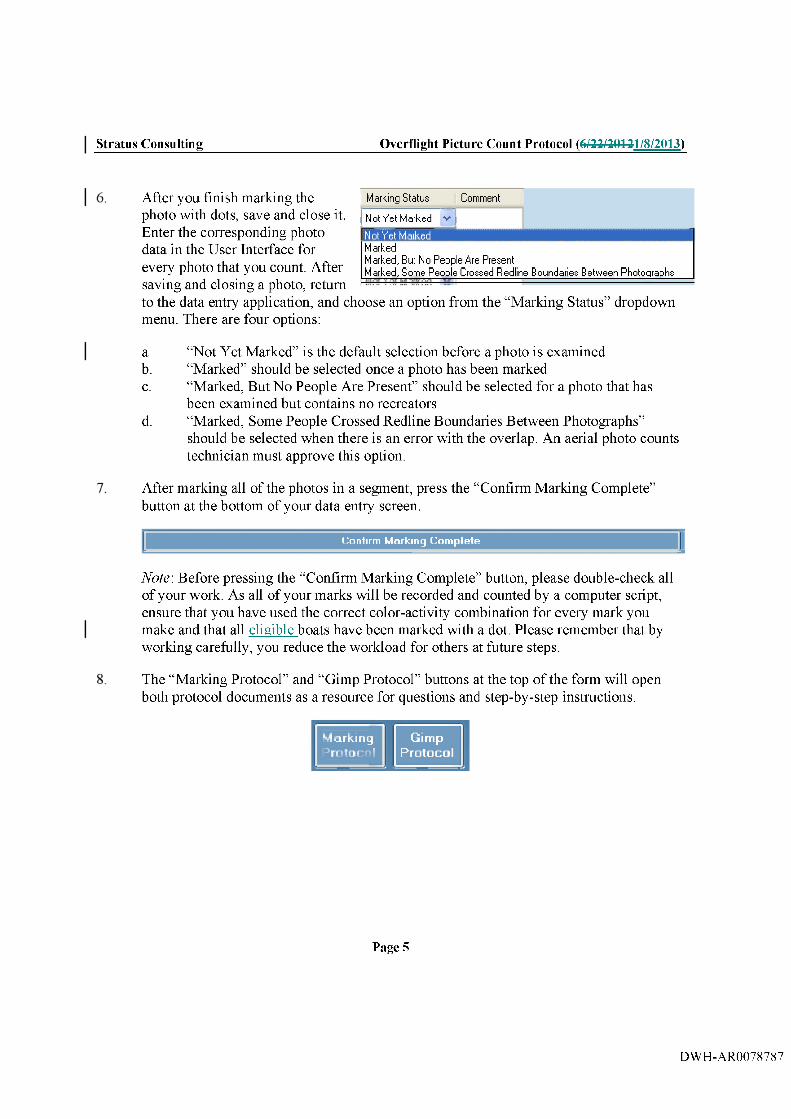
Stratus Consulting Overflight Picture Count Protocol (6/22/20121/8/2013)
Not Yet M arkedM arkedM arked, But No People Are PresentM arked, Som e Peojole C rossed Redline Boundaries B etw een P hotographs
After you finish marking the Marking S ta tu s Comment
photo with dots, save and close it. j Not Yet M arked v |Enter the corresponding photo data in the User Interface for every photo that you count. After saving and closing a photo, return to the data entry application, and choose an option from the “Marking Status” dropdown menu. There are four options:
a. “Not Yet Marked” is the default selection before a photo is examinedb. “Marked” should be selected once a photo has been markedc. “Marked, But No People Are Present” should be selected for a photo that has
been examined but contains no recreatorsd. “Marked, Some People Crossed Redline Boundaries Between Photographs”
should be selected when there is an error with the overlap. An aerial photo counts technician must approve this option.
After marking all of the photos in a segment, press the “Confirm Marking Complete” button at the bottom of your data entry screen.
C o n f i r m M a r k i n g C o m p l e t e
Note: Before pressing the “Confirm Marking Complete” button, please double-check all of your work. As all of your marks will be recorded and counted by a computer script, ensure that you have used the correct color-activity combination for every mark you make and that all eligible boats have been marked with a dot. Please remember that by working carefully, you reduce the workload for others at future steps.
The “Marking Protocol” and “Gimp Protocol” buttons at the top of the form will open both protocol documents as a resource for questions and step-by-step instructions.
mum
Page 5
DWH-AR0078787

MS Canyon 252Flyover Sampling Disposition Quality Control Protocol
General
► Record all notes in your project notebook► Send all emails pertaining to this project through your MS Canyon 252 email account► Use your MS Canyon 252 email account for emails pertaining to this project only.
Stratus Consulting Points of Contact
► Administrative/scheduling; Kevin Lazar► Data process manager: Justin Steim
Definitions
► Segment: A sampled geographic area of shoreliner► Flight date: A single flight that occurs on a specific date at a previously scheduled time► Flyover: The sampling of a specific segment on a specific date.
Task 5: Flyover Sampling Disposition
In this stentask. you will review the overlap and coverage selections sampling disposition information for processed flyovers- to ensure selections have been applied consistentlv The sampling disposition of a flyover consists of three parameters: missing photos, coverage, and overlap. All three of these parameters apply to the entire flyover; however, coverage and overlap are selected for each photo. All of the photos in a flyover are stitchedgrouped together, and this review is used to determine if any designated count area is missing from the segment.flvover.
1. Open the Dropdown quality control (QC) form by clicking on the link on your desktop.Then click on Dropdown Menu QC in the form that opens.
DWH-AR0078788

Stratus Consulting Flyover Sampling Disposition Quality Control Protocol (6/22/20121/8/2013)
Q C T a s It !
Assignments are designated by flight. For each flight you are assigned, you will see the Flight ID, Flyover ID, Region, and Segment number (which you can use to identify the reference segment), at the top left. -Qn-Along the tep-bottom left of this section, vou will see the Missing Photos drop-down field. On right of the form, you will see the current assigned Flyover, the Missing Photos setting for that flyover, and twofour buttons titled “Open Flyover PDF^^-and document” “Open Ref SegReference Segment Document” “Open Protocol Document” and “View Flyover History.”
Drop D own M eru s QC
Flight ID: Flyover ID: Region; Segment:
M issing PhoEos:
O p e n F ly o v e r P D F D o c u m e n t
O p e n R e f e r e n c e S e g m e n t D o c u m e n t
O p e n P ro to c o l D o c u m e n t
View Flyover H istory ]At the bottom of the form,, you will see the total flyovers for the flight, the number of flyovers in your queue, and the flyovers that you have edited. Any flyover that you edited will be reviewed by someone else.
rots! Flyovers in Fiight: 74 Flyovers ie ^ for drop down menu QC: 74 Fiyovers pending another QC:0
Click “Open Flyover PDF document.” A marked (dotted and counted) version of the flyover will open, with interior boundary lines drawn. Click “Open Ref SegReference Segment Document” and the corresponding Reference Segment for that flyover will open.
To begin fhe review, first check the missing photos status of the flyover. This dropdown menu will show that the current setting for the flyover is one of four categories: “No photos are m issing-” “Photos are missing from the beginning- only.” “Photos are missing from the endr only.” or “Photos are missing from the beginning and the endrf
Page 2
DWH-AR0078789

Stratus Consulting Flyover Sampling Disposition Quality Control Protocol (6/22/20121/8/2013)
5. In some cases, photos of the beginning or ending boundary of the segment will not have been captured during the overflight process. This can be determined by the presence or absence of the beginning or ending boundary in the corresponding first or last photo of the flyover. -If the photo is missing the beginning boundary only, select “Photos are missing from the beginning.” If the flyover is missing the ending boundary only, select “Photos are missing from the end.” If both boundaries are missing (the beginning and ending boundary), then select “Photos are missing from the beginning and the end” from the menu. If both boundaries are shown (i.e., any part of the beginning or ending boundary), select “No photos are missing.”
6. In the data grid below, you will see three columnsjj. “Photo Name,” “Coverage,” and “Overlap.”I fp F ly o v e rs=
P h o to Nam e C o v e rag e O verlap
In land a n d v ^ a te r a re a s m issing O v erlaps p rev io u s p h o to ~
A u y _ 2 1 _ 2 0 1 0 _ 2 4 8 7 W dLei d ie d iiiissiiig (bw iiiiiiie is putitiibly e x c lu d e d ) Nu o v e rla p wiLli p rev io u s pliuLu -
A u g _ 2 1 _ 2 0 1 0 _ 2 1 8 9 In land a n d w a t e r a re a s m i» in g •' No o v e rla p w ith p rev iouo p h o tc -
A u g _ 2 1 _ 2 0 1 0 _ 2 4 9 0 In land a n d w a t e r a re a s m issing •»' [ o v e r la p s p rev io u s p h o to TA u g _ 2 1 _ 2 0 1 0 _ 2 4 9 1 In land a n d w a t e r a re a s m issing •»' jp h o to is f ir s t in se r ie s fo r s e g m e n t
7. First, check the “Coverage” selection for each photo. This is to designate if part or all of an area designated for counting is not captured in the photo. If coverage is missing for any of the area categories (Beach Area, Water Area, Pier/Jetty Area, and Other Recreation Area), mark the appropriate combination of missing areas that apply. If the photo is nearly impossible to count due to darkness, select “Darkness” in the coverage drop down menu for that photo. If the photo is nearly impossible to count for some other reason (e.g., blurry, foggy, extremely distant, completely obscured by objects), select “Image obscured” from the dropdown menu.
8. Next, check the “Overlap” selection for each photo. “Photo is first in series for this segment” should be applied to the first photo of the segment (the leftmost boundary line). Select “Overlaps previous photo” if the photo has an overlap extending across the beach and into the water for the photo. If you are not sure, double check the overlap. Keep in mind that other photos another photo in the flyover could contain have the area that is not
3verlapping in two consecutive photos (e.g.. this happens with photos o f a
Page 3
DWH-AR0078790

Stratus Consulting Flyover Sampling Disposition Quality Control Protocol (6/22/20121/8/2013)
pier on occasion). If this is the case, the selection “Overlaps previous photo” applies. If there is no overlap extending across the beach into the water and no other photo in the segment shows the missing overlap, select “No overlap with previous photo” from the dropdown menu for that photo.
Once all three categories (Missing Photos, Coverage, and Overlap) have been checked and updated as necessary, press the “Get Next Flyover” button. A confirmation box will appear to confirm that you have finished the review of a flyover. Select “Cancel” if you need to make additional changes or “Ok” if you have completed making changes.
G e t N ex t F lyover
10. f t eAfter pushing the button the flyover will be submitted, your queue will decrease by one, and you will receive a new flyover from that flight to complete. Repeat these steps for each flyover in the flight. Upon completion, a new flight will be assigned. To quit, complete the flyover you are working on, and click “Get Next Flyover.” You will receive a new flyover. Click the red “X” in the top right comer and the flight will return to your queue.
Page 4
DWH-AR0078791

MS Canyon 252Flyover Qnality Control Protocol (“10% Checks”)
General
► Record all notes in your project notebook► Send all emails pertaining to this project through your MS Canyon 252 email account► Use your MS Canyon 252 email account for emails pertaining to this project only^
Stratus Consulting Points of Contact
► Administrative/scheduling; Kevin Lazar► Data process manager: Justin Steim
Definitions
► Segment: A sampled geographic area of shoreline► Flight date: A single flight that occurs on a specific date at a previously scheduled time-► Flyover: The sampling of a specific segment on a specific date► Reference Document: Contains redlined reference photos of a segment, redlined to show
segment boundariesT: it is used for use in creating a Mark Documentv► Mark Document: Contains photos from a particular flyover that have been marked with
redlinesredline boundaries, areas of overlap across photos, and recreator count dots.
Task 6: Flyover Quality Control (10% Checks)
Overview and Background Information for Flyover Quality Control (QC) Verification
In this processtask. you will review completed flyovers to check for redline, overlap, or photo errors that could affect the count area in a segmentflvoven and correct any errors.- Verify the following:
1. The correct photos were selected for the flyoverr
2. The photos were redlined based on the Reference Documents and overlap areas were correctly drawn.
Form Overview
1. Open the “AerialCountsQC” application by clicking the link on your desktop. Click the“ 10% Checks” button to generate a new flyover assignment.
Page 1
DWH-AR0078792

Stratus Consulting MS Canyon 252: Flyover Quality Control Protocol (6/22/20121/8/2013)
Q C T a s k s
D r o p d o w n M e n u Q C
10% C h e c k s
QC Tasks
D ro p d o w n M e n u QC
10% C hecks
2. Each flyover has an associated Flight ID, Flight date, and Segment identifier (region and segment number) listed at the top left of the form. At the top of the document, above the Flyover ID, red text stating, “Flyover is assigned for review,” will indicate if you are reviewing a suggested QC change. There is a “Missing Photos” drop-down menu to indicate if there are missing photos from the flyover. Along the right side of the form are three buttons, one for each Mark Document. Note that the “Open Mark3 PDF” will only function for flyovers that have been processed three times.required a third count during reconciliation. The next three buttons below are used (from left to right) are used to open the directory for the original photos, the Reference Documentreference document, and the Google Earth .kmz file (contains the relevant segment start and end boundaries and photo waypoints).
Page 2
DWH-AR0078793

Stratus Consulting MS Canyon 252: Flyover Quality Control Protocol (6/22/20121/8/2013)
FlynvpT ID : 17422F light date: 1/2/2011S egm ent: NG 5M issing Photos: ]|N o photos are inissing
Open Marfc2 PDF
Open Marks PDF
Flyovers will be assigned for either quality control (QC) or review of changes resulting from someone else’s QC. Red text at the top of the document stating. “Flyover is assigned for review.” will indicate if you are reviewing a suggested QC change.
3. In the grid section of the form, flyover data are listed. “Photo Name” indicates the standardized name for the counted photo. The Mark Documents may not contain the standardized name beneath each photo, but they will contain the photo number (the last four digits) and flight date. “M arkl Count,” “Mark2 Count,” and “MarkS Count” contain the total counts for a photo. “Coverage” and “Overlap” contain descriptive information about the missing area in a photo, if applicable. “Markl Delta,” “Mark2 Delta,” and “Marks Delta” are used to enter an adjustment to one or more of the counts if an error is identified. -These columns are enabled by checking the box in the “Change Indicator” column.
]an_Q 2_2Q ll_0021 0 0 0 No missing a rea O verlaps p rev ious photo □► 0 0 0 No missing a re s No overlap w ith prev ious photo 0
]a n _ 0 2 _ 2 0 ll_ 0 0 1 9 0 0 0 No missing a rea O verlaps p rev ious photo □
M arkl M ark l Mark2 Mark2 Mark3 Mark3 _ ^ , C hange Photo Name - i _ C overage O verlap . ® C oun t D elta C o u n t D elta C oun t Delta ” ^ Ind ica to r
>
]an_02_2011_0021 0 0 0 No missing a rea O verlaps p rev ious photo B0 0 0 No m issing a rea No ov erlap w ith prev ious ptioto □
jan_02 _ 2 0 1 1 _ 0 0 1 9 0 0 0 NO missing area O verlaps p rev ious photo B
Flyover QC Process
Flyovers will belf the form does not have the tex t “Flyover is assigned for eftherreview.” follow the steps below to QC or review of changes resulting from a QC process performed. For the initial QC. follow the steps below normally.the flyover. If the form has the textT,, “Flyover is assigned for review,” follow the steps below only forfocusing on the photo having(s) with nonnull delta values.
4. Verify that all available segment photos were added to the flyover.
a. Open the photo directory, Google Earth .kmz file, and all Mark Documents.
b. Check that all available photos of the flyover were included in each Mark Document hased on the Google Earth start and end boundaries and photo
Page 3
DWH-AR0078794

Stratus Consulting MS Canyon 252: Flyover Quality Control Protocol (6/22/20121/8/2013)
waypoints. Also check that no additional photos unrelated to the flyover were included.
I f item h is not verified, continue to item c. Otherwise, continue to Step 5.
c. Click the box titled. “Click to add or remove photo-^ and enter the photo number in the #### format using leading zeroes if necessary. If vou are adding a photo, the program will recognize this based on the entered photo number, and an edit version of the photo will open in GIMP.
d. If vou are adding a photo, continue with step 4d. Otherwise skip to step 4e. Open the Reference Document and review the raw photo(s) that were incorrectly excluded or included infrom the Mark Documents.
• If a photo is missing from the flyover, click “BUTTON TBD” and type the photo number you are adding. This will open an edit version of the photo in GIMP. InClick on the GIMP menu titled “Layer,” click on “New LaverA” and in the box that opens. Type tvpe “Redline” for the layer namer-keeB Keep the default height and width information, and the default setting “Transparency.” Click “OK” and a new layer will be added. Using the provided colors (purple for redlinessegment boundaries, light green for subtracting overlap areas, and dark green for adding overlap) areas), draw the edit linessegment boundaries and overlap areas for the corresponding photofs) in this new layer. Once this is complete, click “File” and choose “Save As,” then select “Photoshop Document” from the “Select File Type” box. Save the added photo in the corresponding Region and flightdateflight date directory located in:WDEEP W ATER\deep waters \W orking V ol2\P SD\T enPctExports.
\\DEEPWATER\deepwater3\W orkingV ol2\P SD\T enPctExports.
Page 4
DWH-AR0078795

Stratus Consulting MS Canyon 252: Flyover Quality Control Protocol (6/22/20121/8/2013)
Count recreators that appear in photos that were incorrectly excluded from the Mark Document. Only include recreators within the redlinesegment boundaries and do not count recreators in areas that overlap with photos included in the Mark Document. If this count is greater than zero, eltekClick the “Change Indicator” check box for the photo that is closest
C hangeI n d ic a to r
in photo number to the excluded photo(s).
Enter the count in each of the “Mark# Delta” columns in the selected photo’s row (i.e., enter the count from the Markl Document in “Markl Delta^,^ the count from the Mark2 Document in “Mark2 Delta,” and so on). Enter the count as a positive number (or 0) because these recreators were incorrectly excluded.
e. If vou are removing a photo, continue with step 4e. Otherwise skip to step 5. Foreach Mark Document, count the recreator dots that appear in photos that were incorrectly included. If any of these counts is greater than zero, clickClick the “Change Indicator” check box for the associated photo(s). Enter the count ofrecreator dots in the respective “Mark# Delta” columns in the selected photo’srow. Enter the count as a negative number (or 0) because these recreators were incorrectly included.
5. Verify that all photos were correctly redlined according to the Reference Document andthat overlap areas across the photos were drawn correctly.
a. Open the Reference Document and all Mark Documents.
b. Check that redlines were drawn correctly using the Reference Document. Verify that overlap areas were also drawn correctly.
I f item b is not verified, continue to item c. Otherwise, continue to Step 6.
c. Using the Reference and Mark Documents:
• For each photo where overlap or redlines were drawn incorrectly, open the edit version of the photor bv clicking the photo name. Using the provided colors (purple for redlinessegment boundaries, light green for subtracting
Page 5
DWH-AR0078796

Stratus Consulting MS Canyon 252: Flyover Quality Control Protocol (6/22/20121/8/2013)
overlap areas, and dark green for adding overlap areas), draw the edit Irnescorrect segment boundaries and overlap areas for the corresponding photo-^ Save and close the photo when edits are complete.
For each Mark Document, count recreators that should have been included in the counts, but were excluded because of incorrectly drawn redlines or overlap areas. If anv of these counts is greater than zero. clickClick the “Change Indicator” check box for the associated photo(s). Enter the count of recreators in the respective “Mark# Delta” columns in the selected photo’s row. Enter the count as a positive number (or 0) because these recreators were incorrectly excluded.
For each Mark Document, count recreators that should have been excluded in the counts, but were included because of incorrectly drawn redlines or overlap areas. If any of those counts is greater than zero, eltekClick the “Change Indicator” check box for the associated photo(s). Enter the count of recreators in the respective “Mark# Delta” columns in the selected photo’s row. Enter the count as a negative number (or 0) because these recreators were incorrectly included.
6. At the bottom of the form are the completion buttons, which are used once the above verification steps have been completed. To complete the current assigned flyover and continue to the next assignment, click “Finish flyover and get next flyover.” Otherwise, click “Finish flyover and exit QC form” to complete the assigned flyover and exit the application.
F in is h F ly o v e r an d G e t N e x t F ly o v e r
F in ish F lyover and E x it QC Form
F inish F lyover and Get Next F lyover
F in ish F lyover and E x it Q C Form
Page 6
DWH-AR0078797

2011 H um an U se Aerial Im agery Work Plan11/14/2011
Exhibit H. Modifications of BP’s Protocols
DWH-AR0078798

2011 H um an U se Aerial Im agery Work Plan11/14/2011
Modifications of BP’s Aerial Photography Protocols
The methods for the aerial photography coordinated by the BP and the Avant Media Group for the month of April 2012 were the same as those articulated in the cooperative agreement. From May 1, 2012 through September 30, 2012, BP used the methods similar to those in effect prior to the cooperative agreement, summarized below. No further human use aerial flights were taken after September 30, 2012.
Protocol
Avant Media Group performed aerial photography using aircraft provided by BP or its contractors. The flights were typically conducted several hundred feet offshore at approximately 500 feet altitude above ground level and at airspeed of approximately 120 knots. All flights adhered to BP safety requirements for the MC-252 incident. The shoreline/water interface was centered horizontally in the photo. The zoom was adjusted to be as close in as practical while capturing the entire shoreline/heach area above the beach (generally to at least the first road if applicable), and the water. A photograph was taken approximately every three seconds, depending on airspeed, with the goal of achieving an approximate 25% overlap in the photos. Photos were geotagged by the photographer during the flight. Avant Media Group downloaded and maintained a backup of the photos and track logs. Avant Media Group provided Cardno ENTRIX external hard drives containing the geotagged photos and flight track logs. Avant Media Group followed established chain-of-custody process. Cardno ENTRIX verified that data for the scheduled flights was contained on the hard drives. If there was an omission or error, Cardno ENTRIX worked with Avant Media Group to obtain the correct data.
Schedule
All photographs were taken by Avant Media Group. In April 2012, photos were taken according to the schedule in the cooperative agreement, which specified that the Trustee representatives collect photos for the coasts of Mississippi, Alabama, the Florida Panhandle and the Florida Keys, and BP representatives collect photos for the coasts of Western Eouisiana and Texas. From May 1, 2012 through September 30, 2012, photos were laken in Ihree geographic zones: Northern Gulf (Waveland, MS to Cape San Bias, FL), Louisiana/Texas^ (Houma, LA to Port Arthur (Sahine Pass), LA), and West Florida (Clearwater, FL to the Florida Keys).
BP’s flight schedule typically included paired flights, on which flights were flown for all geographic zones on one randomly selected day per weekend. Over holiday weekends BP generally scheduled flights each day of the weekend. The flights for the entire West Florida Zone required multi-day out-and-back trips (where photos were taken in each direction) and were performed every other weekend. On the weekends when BP did not schedule multi-day flights, BP performed flights over a subset of the West Florida Zone (the Clearwater/St. Petersburg area). For the Louisiana/Texas Zone, flights were completed in a single day out-and-back trip.In addition, BP scheduled one flight in the Northern Gulf Zone on one randomly selected
This zone formerly was defined as the coasts of Louisiana and Texas, to the Mexico border.
DWH-AR0078799

2011 H um an U se Aerial Im agery Work Plan11/14/2011
weekday per week. The aerial data collection generally occurred between the hours of 8 am and 5 pm. If flights were cancelled due to inclement weather or other reasons (e.g. logistics), they were rescheduled on like days (i.e., if a weekend day flight was cancelled, the flight would be rescheduled for another weekend day).
BP will provide raw files (e.g., photos and track logs) consistent with the previous cooperative agreement on a monthly basis beginning 30 days after execution of the Second Amendment. BP will count twenty percent of the BP photos taken each month between April 1, 2012 and September 30, 2012, consistent with the protocols in place before the Work Plan. BP will commence counting of the BP photos taken during April - September 2012 upon execution of the second amendment to the work plan. BP’s April - May 2012 data will be delivered approximately 60 days after execution. The June - September 2012 data will be delivered thereafter in monthly installments thereafter as the data become available. BP counts of Trustee photos collected in April 2012 will be delivered 60 days after receipt of such photos.
DWH-AR0078800

2011 H um an U se Aerial Im agery Work Plan11/14/2011
Exhibit I. Trustees’ Estimated Budget (Jauuary 1, 2013 - September 30, 2013)
DWH-AR0078801

MemorandumTo: Katherine Pease, NOAA Office of General Council;
Norman Meade, NOAA Office of Response and Restoration
From: David Chapman, Eric Horsch, and Justin Stein, Stratus Consulting Inc.
Date: 1/7/2013
Subject: Budget Estimate for Aerial Photography and Processing
Overview
Overflights are being conducted to take high-definition photographs that record recreational use in coastal areas potentially impacted by the Deepwater Horizon oil spill. The 2011 Human Use Aerial Imagery Work Plan between the Trustees and BP covered the collection of overflight photographs through March 31, 2012 and the transmission of raw data and processed files through June 30, 2012. The Trustees are in discussions with BP about an additional work plan that would cover the period of April 1, 2012 through September 30, 2013. This memorandum describes the following costs:
► Transmission of raw data and currently available processed files for photographs taken during the period of April 1, 2012 through December 31, 2012
► Overflight photography for the period of January 1, 2013 through June 30, 2013^ and transmission of the raw photographs
► Processing of photographs and transmission of processed files for photographs taken between October 1, 2012 and June 30, 2013. It is anticipated that the final transmission will occur prior to September 30, 2013.
These costs are divided into three tasks, as described below.
Task 1: Data Collection
Avant Media Group conducts the overflights and transmits the resulting aerial photographs and waypoints to Stratus Consulting. Overflights are conducted to collect data for the Trustees via two routes: the “North Coast” and the “Peninsula” routes. These overflights are scheduled four times a week for each route: two on weekdays (Mondays through Thursdays) and two on weekend days (Fridays through Sundays).
1. June 30, 2013 is used as the end date for this extension of the Aerial Imagery Work Plan, but the Trustees may choose to end overflight data collection before or after this date.
DWH-AR0078802

Stratus Consulting______________________________________________________Memorandum (1/7/2013)
The cost for Task 1 is $643,175.
Task 2: Photograph Processing
Raw photographs and waypoints are backed up onsite at Stratus Consulting and prepped for processing. Approximately 20 data processors, managed by Stratus Consulting staff, process sampled photographs according to the developed protocols.
The cost for Task 2 is $1,958,404.
Task 3: Data Transmission
All raw photographs, waypoints, and processed photographs will be delivered according to the 2013 Human Use Aerial Imagery Work Plan. Labor will he necessary to reformat and compile the processed photograph files for transmission. All data and files generated through September 2013 will be transmitted on external hard drives.
The cost for Task 3 is $44,620.
The total cost for all three tasks is $2,646,199.
Page 2
DWH-AR0078803