missiyist aid microstructure; ' a...
TRANSCRIPT

Emissivity and microstructure; a study of theconsistent irregularities of the emissivity
of certain metals from a microscopic basis
Item Type text; Thesis-Reproduction (electronic)
Authors Resley, Robert Dill, 1929-
Publisher The University of Arizona.
Rights Copyright © is held by the author. Digital access to this materialis made possible by the University Libraries, University of Arizona.Further transmission, reproduction or presentation (such aspublic display or performance) of protected items is prohibitedexcept with permission of the author.
Download date 04/06/2018 17:17:12
Link to Item http://hdl.handle.net/10150/319417

■' A SmDImiSSIYIST AID MICROSTRUCTURE;
OF THE COITSISTEHT IRREGULARITIES' OF' THE EMISSI7ITT OF CERTAIH .BffiTALS" FROM A MICROSCOPIC BASIS
. ;; . ' ;: Robert Resley., "
A Thesis SuMitted to; the Faculty of the’BEPARTMEBT OF MECHAHICAL EICIHEERIHC .
In Partial Fulfillment of the Requirements . ' For the Degree of.
* . M A S m ..OF, SCIEIOB: In the Graduate College
v;':: ; v;;:--.':thbv:uhiiersi:ti o f'arizoia v.; v \
1 9 6 2

STATEMENT BY AUTHOR
This thesis has been submitted in partial fulfillment of requirements for an advanced degree at The University of Arizona and is deposited in The University Library to be made available to borrowers under rules of the Library.
Brief quotations from this thesis are allowable without special permission, provided that accurate acknowledgment of source is made. Requests for permission for extended quotation from or reproduction of this manuscript in whole or in part may be granted by the head of the major department or the Lean of the Graduate College when in their judgment the proposed use of the material is in the interests of scholarship. In all other instances, however, permission must be obtained from the author.
SIGNED:
APPROVAL BY THESIS DIRECTOR
This thesis has been approved on the date shown below:
W -3 0 z ^ 2-
/ Date JAssociate^Professor of Mechanical Engineering
ii
AOKHOiiLEDGMBN'I
Tlie author wishes to express his appreciation for the patience, understanding, and assistance given ■ by Professor AV Ealph Yappel in the preparation of this thesis„
The author also wishes to express his gratitude to JDr o Behjamih S'a Mesick for his valuable suggestions 1 during the preparation of this thesis« • ;
ill

TABLE OP COHTESTS
PageDBFISITIOS 'OF SYMBOLS , .;'viChapter
1 IITROLUOTIOI 0 6 0
1 © 1 B-X £>10 ry o e o » o o o © o o e © e o 11 o 2 P r o hL em « « o © « o, © o o © » © © © 21.3' Approach to the Problem © © © © © © 3
REVIEW OF LITERATURE AID EXPERIMMTS © © . 52©1 Literature•Searched . » . © © © © © 52©2 Previous Experimentations,, ©' © © © © 72©3 Personal Correspondence© . © © © © © 10
CORBELATTOS OF WALE’S EXPERIMEIT © © . © © © 133© 1 Introduction © © © © © © © © ©■©.© © 133»2 Area of Undetermined Behavior© © © © 133.3 Microstructure of the.Metal© © © © . 153.4 Explanation of Undetermined
Behavior © © n© © © © © © © © © © © 153*5 R osults © © © © G o © © © © © © © © 19
SUGGESTED EXPERIMMTAL APPROACH © © © © © '© . 214©1 Introduction © © © © © © © © © © . © 214 © 2 Theory © © © © « © © © © © © © © © © 224©3 General Procedure© © © © © © © © © © 264©3©123tiissiyity Calculation © © © © ©. © 274©3©2 Density Calculation© © © © © © © © 294.3.3 Correlation of the Results © ©. © ©. 334*4 Apparatus Required for Experimen
tation © © o © © © © g © © © © o © 344©4©1 Apparatus Required for Density
Calculations © ©■© © © © © © © © 344,4©2 Apparatus Required for Emissivity
. Calculations © © © © » © © © © © 364.4.3 Interconnection of Apparatus © © © 404®5 Alternate Experimental Approach® © © 42
iv

'table o$v ooHiira (oont$d) .Oiiapter Page
5 OOHOLUSIOIS AIL REOOHMBimTIOlSe » . o . * 4 5, 5°1 Conclusions . o . . * •' • > • +■ • » 455,2 Recommendations «, » t * «, • , . . . <, 46
APPBH3DIX A, Cost of Experimental Apparatus, . , . 4?APPEHDIl B» Sample Calculations for Density * » .-» 48APPBRLIX 0, Availability of Experimental Apparatus
at the UniTersity- of Arizona 49REPERMCES. ; » » » o ^ ». ;v' . ' 50BAeKOROtJI]) REPERE1CES, •, . . . , , , , - 0 , s ' 0 52
v

DEFINITION OF SYMBOLS
Symbols Definitiona = lattice parameterb = subscript for black bodyd = interplanar spacing, cmf = total radiant flux, BTU/sec-ft2
h,k,1 = Miller Indiceso = subscript for normal fluxq = energy emitted per unit time,BTU/secr = radius of hemisphere of integration,
ftt = time, secondsu = subscript for unknown surface
pA = area emitting radiation energy, ftQ = total energy emitted by area, BTUsT = absolute temperature, °Rankine
(T" = Stefan-Boltzmann constant, BTU/sec-ft2-OR4
C = total hemispherical emissivity0 = azimuth angle of hemisphere, radiansA = wavelength of X-ray radiation, cm0 = elevation angle of hemisphere,
radians
vi

V ■ '■ ' ; - GiBESia. 1 ■ '- ' : ■ ''b •'7" v . : ■ :: IHfRGDUGflOH : ' ' :
Iwl . Hlstorjo With the advent of the space age _ the speed of aireraft and pilotlessTehieles increased into the high supersonic and hypersonic range« Because of this increase in speeds an increase in the heating of the Tehieie was noted*. This increase in the temperature of the vehicle had to he controlled to keep the temperature ■ within the structurally tolerable limits*
Gooling by radiation, either alone or in combination with other cooling methods, is one of the most promising means of keeping the temperature within the Petuired limits® Radiant cooling is attractive because of its simplicity and reliability as compared with other cooling methods* Materials which are poor radiators may be coated with a thinilayer of a material of good .
, radiation properties thus making the original material a good radiator. The rate of loss of heat by radiation is : directly proportional to the ■ total hemiSpherical;emissivity of the surface. Therefore, in view of these
. cohsiderations, the Pilotless Aircraft Research Division

• V ' : .. ■ - ■■■■ • 2of the Langley Aeronautical. Xjaboratory. (l )'e‘ began the investigation of h.igh-= emissivity surfaces from the vie fpoint of their application to the cooling of supersonic and hypersonic.aircrafto ■
1 o2 Problem^ Part of Langley Aeronautical Laboratory s general research program on the aerodynamic 7 heating of supersonic and hypersonic aircraft was a report on the measurements of total hemispherical emissivity of various oxidized metals at high temperatures = The tests pertaining to this part of the research were performed by William E=.Wade (2)= Wade tested eight different metals in : quiescent air for their emissivity at different temperatures» The metals tested were stainless steel (AlBl-303)» mild steel (AISI-01020), ; titanium" (TiGA-Ti~75A) V titanium alloy (0.8-120) s copper, aluminum (AA-3 0 0 3), molybdenum, and tantalum« Measurements of the radiant flux were made with a thermopile which had been calibrated by use of a reference black body*'Temperatures were measured by use of thermocouples.attached . to the specimenso
The results of this experiment were promising in that a stable exide coating of high emissivity was obtained for all metals except molybdenum! and tantaluiyu- All of the - results ' of ■. the experiment were explainable except for ‘ . '; a sudden'decrease in. emissivity at 1400°F for the titanium
. '""Numbers in parenthesis identify references®

alloy :(RS-120) o numerous specimens of this titanium"alloy 20) :were tested and all; had.ytlie same sudden decrease
in emissivity at 14000I’» This consistent irregularity of ■ the emissivity of . this metal was the •basisfor.: this..thesiS o It was felt, that any consistent behavior had an explanation which may have numerous f a c t o r s hearing on the solution. But, if a" few or even, one of the. factors could he found-, it is possihle that the behavior may he- explained.
This study approached the problem from a micro- structural basis.. This approach permitted a study of the micro structure and changes in emissivi ty in an endeavor to obtain some correlation. This approach was decided upon after a preliminary investigation did show a change in the microstructure of the titanium alloy (R8-120) at the temperature of l400°Fo . Also, Wade did not appear to
' consider the microstructure of the metal.1. 3 Annroaoh to the Problem. The exact approach
taken during the study of this problem was, first, to review all literature having a bearing on the subject, second, to analyze any results obtained from experiments which- were performed concerning the thesis subject, and third, to .correspond personally with an authority in.the field: to deteirmlhe if there' was; any information of Value " which had.hot been published„
With all OS the above Information a search and study .was made to determine if there may be a correlation between " the consistent irregular behavior noticed by Wade and the micrqstructure of the metalSince a correlation was found, it should be confirmed by an extended experimental 'study» Such an.experimental •study would have to be quite extensive with requirements which are far beyond the endeavors of this study® .However/ a suggested experimental program has been' included in this study® This suggested program includes
% theory, apparatus required, and procedure, for experimenta- 'tion, which should facilitate the initial phase .of; the •' experimentation® ' The experimentation should not be limited to just the metal used-in Wade’s experiment, titanium alloy : ;(ES"1 2 0 ).3, '.but .shbuid;be': extended- to , include other materials

OHiPm'2REtim OF LITEEATUEi; AHD EXPlRIMEITS
2=1 Literature ,gearcliedo In searching the literature available ou the subject of emlsslvlty,' the lack.■ of consideration of emlsslvlty from, a mlcrostructural standpoint became. evident = Experiments have been performed 'and charts have been prepared in an endeavor to give some values of emissivity at certain temperatures for certain materials= Generally, most of.the information, available has not considered the variation of emissivity with micro structure. .However, there were some books which did present some facts which did assist in a microstructural ; analysis. : ;. v v-.. : . .
In 1914 the English translation of Planck’s theoryof heat radiation was. made available (3). Planck commented .• that emission of radiation always take place at the expense of energy and that only material particles, not geometrical volumes or surfaces can emit heat rays. Planck also stated
, that .the surface of a body never emits rays, but rather .it. •allows part of the rays coming from the interior to passthrough. Planck noted that the coefficient of emission..

' Galled' emissivitys, depends not only on the- frequency of the emitting substances, but also, in a very- complicated way, on the physical and chemical processes that take place in the body„ : 'Planck8s book was a most complete work and in most of the following literature ;one can see its influence.
; In 1935s Sara and Srivastava commented that radiation was dependent on the physical properties of the body (4).-Sara and Srivastava, stressed the macrostructure as most ' ' authors; did and left the micro structure analysis to the /metallurgistV ; v:';- /''t : ■ -■ ' ::/:; / - 'In 1942:, . McAdams in his book (5) and Brown and Marco ' ■(S) in/ their- book.’ stressed: the point that the emission, of radiation is dependent'on the nature of the body, in addificn to its temperature^ - ' .' I n 1,9 4 9s' Businberre gave the same conclusions asMcAdams'(7)= In 1959s Jakob and Hawkins:commented that the transfer of energy by radiation was composed of three . distinct' components (8)0 The first of these components is the conversion of the thermal energy into electro-magnetic wave motion, ..the second component is the passage of the wave motion through the intervening space to the sensing body, and. the,-, third 'Component i s : th e reconversion Of the wave-motion ■.energy into thermal energy by the sensing (cold) body*The micros true turaLan'aly sis of these three components

. y . ■. - . . ■ ■ . 7concerns mainly tlie increase in energy of the electrons and
•then their release of this energy as electro-magnetic waveso These waves must find their way.to the surface to he emitted as radiation to the cold "body» laturallys on their way to the surface some may he absorbed or reflected so the : microstructure can have an effect on the radiationo
Also in 1959, Eckert and Drake noted that;, although v" considerable knowledge can he obtained on emissivity from •'a macroscopic study, for a complete knowledge of the subject ; a study of the radiation and micro structure is necessary .(9 ). ICkert and Drake were the only authors of those noted in this thesis that mentioned the need for a study on emissivity from the standpoint of micro structure e
This Concludes the comments that were available from the books searched in the field of .emissivity and micro- structureo The:lack of’literature in this field is just
. " further evidence of ,the need for more study and correlation
. - between the'engineers and scientists = .2»2. Prevloiiserimentations. Although the • ■ :
v literature has"'been rather f general; in "nature in reference .to this study, there have been a few experiments performed which have a close relation to this study„
In 1943'., Wahlin and Wright conducted an experiment .- on emissivitles and temperatures for some metals of the iron

- group (TO) e la tlielr experiment--they noted the sudden change of emtsslvity as Wade did, in his,experiment= However, : Wahiih and Wright had their specimen’in a vacuum during .. experimehtation while Wade kept his specimen in the local quiescent airo There were a few other minor differences in apparatus.and procedure which had little effect on the ' results» ; ; : ; '• ■:
/ ifahlin and Wright noticed that over the range of temperatures covered (1500°? — 20G0°3?) the emissivity was nearly constant for iron except where the micro structure changed from alpha, the body centered cubic, to gamma, the ■' face centered cubic (11 )o The point where the microstrueture ■ makes, this change in iron is the point (1 2) 0 This was the . first experiment in this field by these men and' they Commented •that future4 experiments would be" planned to investigate ’this change /in.emi ssivityT Thi S initial report discussed the . • apparatus and prboedure thoroughly and commented only briefly on ..'the results "of bthe experiment®
■i In 1948, Wahl in and .Knop continued this research , .with an experiment on the emissivities and temperatures of ' iron and cobalt (13)» ■ This experiment utilized the Same ; theoryV apparatus, and procedure of the previously mentioned Wahlin .and,Wright experiments The results of this experiment : for iron Showed the sudden.decrease in emissivity at the Ay point:previously mentioneds This experiment also noted the

sudden increase at. the A4 point wheii thetemperature was increa,sed to that points' The A4 point (2550oF)corresponds to that temperature at which the crystal structure of the iron changes from the gamma structure» the face centered cubic» to the dhlta structure, the body centered cubico It should be noted here that the face.centered cubiccrystal structure is more dense than the body centered cubic'Lorystal structure, Therefore, when the emisslvity of the - iron decreased at the Ag point, the crystal structure was ;changing to the more dense crystal structure» And when the emissivity;.increased at the A4 point, the crystal structure was changing to' a less dense crystal structure<> A possible correlation at this point would be that when the density of ': the crystal structure'increases the emissivity decreases, and when the density of the crystal structure decreases the . emissivity of the:metal increaseso' ; The second metal considered in Wahl in: and" Khop \s
experiment was cobalt,,. ' The emissivity of cobalt-was rather consistent until the Ourle Point was reached =, The Curie Point corresponds with the temperature where ferromagnetism 'disappears .from a ferromagnetic' metal and what was. once /'; a well, ordered metal becomes a .disordered metal (12). ■ In this experiment.the emissivity increased when the Curie Point was reachedo Cobalt, at the Curie Point, experiences a positive magnetostrictiono This positive magnetostriction •
caused a deqrease in the density of the cohalt when the temperature was' increased to the Curie Temperature0
. In the conclusions.to this experiment Wahlin and Khop suggested the possihility of noting structural , changes in metals hy plotting a graph with temperature and emissiTity as ahscissn and ordinate j respectivelyo To.' illustrate the marked increase or decrease of emisslvity witnessed hy Wahlin and Knop their results are presented on Figures, 2« 1 and -202 (13) °
Also in the same year$ 19489 Knop prepared another ■experiment,(14)o Knop®s experiment was concerned with the emisslvity of.the iron-tungsten alloy.and the iron=cobalt
: alloyo.: His results on this experiment were consistent with . the previous experiments. He. utilised ;the same, theory,■ apparatuss and procedure as the two previous experiments® Howeverj in the.conclusions Knop mentioned the correspondence between the density and emissivlty®
'.This.0oncludes the experiments; which have a relation to j:hi8': theslso' These experiments present the consideration that there may be a correlation between the density of a metal -and if s. emisslvity®. From all three of these experiments results, were produced. which showed.the emisslvity varying inversely with the Hensity of the metal.■ 2.®3 Personal Correspondences After comparing the literature and experimental results$ it was felt that if

11
w*£
.345
.335
.325
.315
"IEOH"
Aj (at 11730)
_L
«-aA(a t 1677°)
1200° 1*00° 1600°Temperature °K
PIomtE 2.1WAHL IN111 AND KJTOP'3 BXPEHIHtiNIAL 2ESDLT3 FOR IRON. (Reference 13)
.350
W.34.O
5 .333 S .320tI
COBALT Ourle Point (at 1378°)
\X
XX
1250° 13555------- 1450°-----------Temperature °K
PIGT7REWAHL IN'S AND lOiCP’S BXPBRIMBNTAL RESULTS FOR COBALT. (Reference 13)
. ■ ' . ■: 12
there .were arty other information, available which had not been published one of the authorities would know of it*A letter was sent to Professor Wahlin asking for any additional references on the subject* Professor Wahlin s
■ reply. contained no reference to. additional publications other than a comment that he had done a similar, study for
; the Manhattan-Project on uranium, with the same results.. His-final paragraph was very conclusive, it follows: "In general, you can say that whenever the change is such as to cause an increase in the density of the material the
.emissive power goes down, and when the density is decreased the-emissive power' goes up *" . (15). I’his brief and clear - summary of his.work in this field should provide a desire to investigate the emissivlty and density of materials*
:fhis is not meant to be a complete solution, to this ; problem but only a step in that .direction e . Planck.1 s comment, that, the .emissivlty is dependent',, in a very complicated way, upon the - physical and chemical processes of the material howfseems 'to be Valid* y- \

' ; o m m ; 3 ,
GOSEEI'A'riOI GF T O B 8 S BXPBHiraHT
f .. 3° 1: v.I]i1}roducl3ioiio " Jii coiiBidersi'fcioii of the 'literatui'e seahchedj' the'/experimeiits meiitionedg and the comment of I'ahlln’s.on the in verse relation of density and . emissivitys it' appears that. a. correlation should he attempted in this area. :
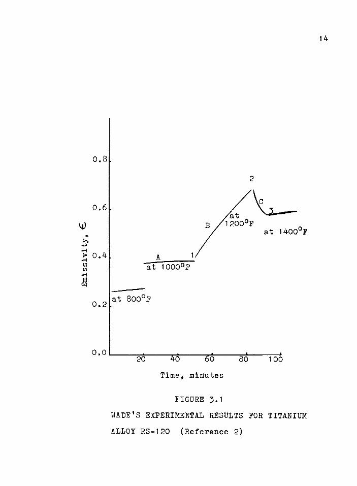
3.2 Area of Undetermined Behavior. The first step must he to ■define; the/ area of- Wade8 s experiment where the uhdetefmined.hehavior was noted. . The metal referred to when Wade' commented on this undetermined behavior was the titanium alloy (B.S-1 20) 0 The .plotted results which Wade obtained
’ during experimentation with this alloy- are reproduced on Bigure S. 1 (2). Letters and numbers have been added on the graph to assist in . this' d From point 2 to point ■3 .on the graph, also ref erred to as line 0, was the area of .
. uhdet'ermined behavior*;. All three of the lines, Ap Bg and 0 ;, represent the measured results for Emissivity versus Time for three different but constant temperatures. Wade used a time, and- emissivity graph rather' than a temperature and emissivity graph since he was interested in the time to establish an oxide coating on the specimen. Line A
13
Emisslvlty,
14
0.4
0.2
0.0 100Time, minutes
FIGURE 3.1WADE'S EXPERIMENTAL RESULTS FOR TITANIUM ALLOY RS-120 (Reference 2)

represents the measured rbsults at a constant temperature of 1G00°Z9 line B at 1200°E? and line 0 at l400°Po The measured results along line 0 are listed as unexplained behavior because the :expected change in emissivity with, an increase in temperature and time of oxidation should have been an increase«, This sudden decrease in emissivity» which was consistent' for all of the titanium alloy (BS=120) specimens tested, cotild not be explained = , Wade f s ,experiment was an endeavor to establish a stable Oxide coating on the surface of metals to increase their' emissivityiolWi%h.an increase in: thlckness of 'oxide coating the emissivity of the surface increasede The emissivity of an oxide is far greater than' the emissivity of a bare metal» So„ as the temperature of the metal was increased the thickness of the oxide coating increasedv until finally the coating was thick enough to have a stable emissiylty<, ; ' , ' ■
Although the measured results for emissivity along line B were as. expected $,. there was a - Very sudden increase in emissivity while the alloy was being, .held at a constant .temperature 0f - 1200<, This .increase in emissivity could be attributed: to an increase in the oxide layer but, as will be seen later? additional matters may have been involved;.■ 3°3 , Micro structure of the Metal«, The results of
. the experiment nearV,the area of undetermined, behavior were studied;, Sow^ a study of the. micros true tur e o f the alloy

V : ' v ■ : 16at these poii].ts, shquldvtie md.e;<e, , "$he cozLstttutional diagram £03? this titanium alloy
(ES-12Q) is reproduced on, Figure ,3->2 (l6)e Additional letters have teen placed on the' diagram to facilitate cross-reference with the experimental results» Point A of Pigure; 342 indicates:a temperature of l000°F which is the same as the temperature for line A of figure 3=1= Point B of figure 342 indicates a temperature of 1200°f which is the same as line B of figure 3«>19 and Point 0 indicates a- temperature of 1400% which: is the same as the. temperatufe of line 0 of figure 3»1»
Phe composition of the titanium alloy (E8-120) was ■ seven per cent manganese0 The temperature points of A» B9 and 0 areoon the seven per.cent manganese composition line.
vAt point A of v figure’ '3 0 2 the micro structure is composed of all hexagohal close packed crystals. At point B the microstructure is composed of approximately one-half hexagonal close packed crystals as hefqre9 and one-half body centered cubic. Half of the'hexagonal close packed crystals at A changed.to the body centered cubic structure. At point 0 the microstructure is all body(centered cubic9 since the remainder of the hexagonal close packed crystals at B have transformed into the body centered crystals.' ' ; 3®4 . Explanation of Undetermined Behavior. With thesudden changes in emi’ssivity as well as the microstructure

Temperature, °P
Beta Crystal
1400Alpha & Beta
Crystals
1200
1000
Alpha Crystals
Manganese, %
FIGURE 3.2CONSTITUTIONAL DIAGRAM: TITANIUM-MANGANESE
(Reference 16)
between the temperatures of 1000°F and 1400°$’j there may be a correlation between the micro structure and the .emissivityv.
Both line A of Figure 3-1 and point A of Figure 3*2 - refer to the condition of the alloy at the same temperature$1000°F $ and they-express the emissivity and microstructure $ respectively, at that temperature® The emissivity is almost constant and the microstructure is a one phase structure of hexagonal close packed crystals 0
Along line B of Figure 3o1 and at point B of Figure ;3®2, which depict the emissivity and microstrueture at 1200°F, the emissivity increases with time® The microstructure in the meantime, changed from the one phase hexagonal close , packed crystals to the two phase structure of half hexagonal close packed and half body centered cubic crystals® If we accept the conclusions that the density of the microstructure and emissivity of the metal vary.inversely, the density at point B :should be less than the density at point A since the .emissivity increased, along-line B bf. Figure 3>1 <> This conclusion is verified since the hexagonal close packed crystals are more dense, than the body centered cubic crystals and the micro structure changed from a one phase structure to a two phase structure =, A' one phase, structure should be more
' uniform, arid have less imperfections' than a two phase ; >. .Structure.® ’ : .r V ■ i ;

■ ' " : / ■■' ■ i9, Along line 0 of Figure 3=1 and point 0 of Figure 3®2
the emissivity and microstrueture of the titanium alloy (HS-120) at the temperature of 1400°F are reTealedo The emissivity decreased and the microstrueture changed from the two.phase crystal 'structure of half hexagonal close packed Varid..half body centered, culic to the one phase crystal .structure, pf all "body • cehtered eubic. The decrease in emissivity should signify: an increase in density if the inverse relation of density and emissivity is correct»The change of the remaining hexagonal close packed crystals to body centered cubic crystals would seem to have the effect of decreasing the density which would be opposite to what is desired. However, the effect of the change from a two phase microstrueture to a single phase microstrueture would have been accompanied by a decrease in the imperfections in the microstrueture which would present a more dense microstructureo Therefore, if the decrease in imperfections more than compensated for the transformation of the hexagonal close packed crystals to the body centered cubic crystals, an increase in the density would have been the result. ..
3.5 Results. The results of this correlation are mixed. There seems to be a correlation between the microstructure and the emissivity of the titanium alloy (KS-I'SO). The explanation of the increase or decrease in the

density of the micrgstructureg although fairly ad equate for ’ pqint Bj jPigure 3 = 2, was rather weak for point ti.' There were more items involved.than, iust the phases present and -imperfeptiohs. The density of the alloy, if it were a single crystals may have been easier to define = However9. the titanium allby, (ES-120) was not a single crystal,
Thepe are. humerous items which may have an eff ect on the density of the alloy. In a report from Frankford Arsenal, D, :Murphy noted many, of the.items which have an effect'on the density, some of which are Voids, lattice, vacancies, grain boundaries, dislocations and the presence . of foreign atoms, hotk/suhstitutional and interstitial (16), ' Wade comm.ented on the ahsprption of nitrogen as a possible cause of the decrease in emissivlty along line G, I’igure 3,1 *
- nitrogen is absorbed by. the titanium alloy as an interstitial atom, ■'The nitrogen atom slips in between the alloy atoms and therefore:increases the density of the microstructure (17)
With the correlation'obtained between the emissivlty and the miprostructure, it is felt that experimental 1 studies should be und.ertaken to attempt to experimentally ■check the correlation . between the emissivity and the ■ microstructure.

\ ‘ " CHAPm .4 . ' ' • : , . ;' V ' '' SUGGISTED BXPBEIMBIIAI, APPROACH '
' „ 4» 1 Intro due This study of the emissirityand microstructure ofcertain metals has .suggested a correlation between the/density of the metal and the sudden unexpected ehanges in emissivity0 Ihis sudden change in ‘emissivity was noted in,Wade8s experiment for the titanium alloy (ES-120)» Wade called this.sudden change "unexpected behavior and could not account for it being present in each specimen of the titanium alloy (RS-120) that was testedo This study has attempted to show some correlation» by use of the constitutional diagram of titanium-manganese and other experimental results» This attempted correlation should be: •substantiated, with, an experiment designed for this purposee Such an experimental arrangement would not be limited to the-study of this One metal but could be utilized, to investigate any other metal desired. ,
Since the experiment is an attempt to provide information on the correlation of a metal8S emissivity and ■ the metal1s density, a plot of Emissivity versus Temperature would reveal any..sudden, changes in the emissivity. At those . ^temperatures where there is a sudden change in the emissivity

22of the metal a comparison of the crystal structure which was present immediately prior to the sudden change in emissivity and the crystal structure following the sudden change should give some evidence of a sudden change in the crystal structure.
A possible means of determining the density of the crystal structure would be by X-ray diffraction. The equipment and procedure for accomplishing this will be discussed later in this chapter.
4.2 Theory. To determine the emissivity of a metallic surface, the energy emitted from the surface must be compared to the energy emitted from a reference black body surface. With a few simplifying considerations the calculations may be restricted to a simple comparison of the radiant flux of the two surfaces.
The radiant energy emitted by a surface is:
Q =£ J r 4 At (1)
where £ is the total hemispherical emissivity of the surface, (Tis the Stefan-Boltzmann radiation constant, T is the absolute temperature of the surface, A is the area of the surface emitting energy, and t is the length of time during which radiation occurs.
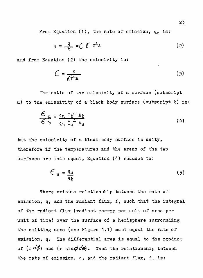
Prom Equation (1), the rate of emission, q, is:
d = _3_ =£ (T t4a (2)
and from Equation (2) the emissivity is:
6 = r (3)
The ratio of the emissivity of a surface (subscript u) to the emissivity of a black body surface (subscript b) is
but the emissivity of a black body surface is unity, therefore if the temperatures and the areas of the two surfaces are made equal, Equation (4) reduces to:
%b
There exists a relationship between the rate of emission, q, and the radiant flux, f, such that the integral of the radiant flux (radiant energy per unit of area per unit of time) over the surface of a hemisphere surrounding the emitting area (see Figure 4.1) must equal the rate of emission, q. The differential area is equal to the product of (r d(f>) and (r sin tffe). Then the relationship between the rate of emission, q, and the radiant flux, f, is:
^ u = 9.U ^b^ -b£ t> It, V Au (4)
(5)

24
/ Area / Emitting 'Radiant ene
> X
FIGURE 4.1HEMISPHERE OF INTEGRATION TO DETERMINE THE RADIANT ENERGY EMITTED FROM AREA "A"
(Reference 1)
i ^25
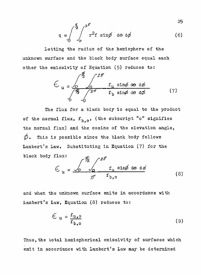
A z= / J r f sin^ de d<>q = / / r f sin^ de (6)“C> ^
Letting the radius of the hemisphere of the unknown surface and the black body surface equal each other the emissivity of Equation (5) reduces to:
A rzir
6 u = Jo Jo fq s W de d;z57 ^ f^ sin^ dS d(2
The flux for a black body is equal to the productof the normal flux, f^ 0, (the subscript "o" signifies the normal flux) and the cosine of the elevation angle,(j) , This is possible since the black body follows Lambert’s Law. Substituting in Equation (7) for the black body flux: ^ ^
6 „ = Jo Jo fu sln^ de ^ff fb,0u jFTT (8)
and when the unknown surface emits in accordance with Lambert’s Law, Equation (8) reduces to:
6 u =fb,o
Thus,the total hemispherical emissivity of surfaces which emit in accordance with Lambert’s Law may be determined

26
Tdj calculating the ratio of the total normal flux from a non-black surface to the total normal flux from a black body surfaceV •
'4d3 General Procedure, i.1 thought this experimental approach has been designed to evaluate experimentally the conclusions suggested for the sudden change in the emissiTity in Wade8s experiment for the titanium alloy (RS-120)V. it need not be so limited. Since two independent calculations will be requiredg ohe for the emissivity and one for the density, a small sample of the titanium alloy (RS*-120) must be prepared for the density calculations and a larger sample for the emissivity calculationsv The density sample size requirements preclude its use for adequate emissive calculations0 Both experiments, one for emissivity and one for density, should use the same stock materiale
The general procedure of the experiment should be first to attempt to determine at what temperatures the emissivity of the metal has sudden changes. Jit these sudden changes in emissivity the temperatures should be noted o- Once the temperatures are determined^ at which the sudden changes in emissivity are noticed# the first phase of the experiment would be complete. In the second phase of the experiment, an attempt should be made to determine the lattice parameters (atomic dimensions of

/;■■■■ ' ; ■ • _ ' ' , 27the crystal structure) of the metal= These parameters can he determined by use of the X-ray camera at the temperature of the metal Just prior to the sudden change in emissivity and at the temperature just following the change« With the lattice parameters and the crystal structure known» the density of the microstructure just prior to and just following the sudden change in emissivity can be determined. In the third phase of the experiment the degree of change in density may, possibly be correlated.If the degree of change in emissivity can be correlated with the..degree of change of density then with any future change in emissiyity the. change of density oould .be calculatedo This completes the, general approach to the .procedure0 A more specific consideration"of each of the three phases follows A . ■
' 4<,3o 1 Emissivity Calculation The purpose of this phase of the experimeht is to develop a graph of the emissivity as it changes with an increase in temperaturee > :/ ’ ", A specimen of the metal to be tested having no. larger 'than' a 1/8 sq ft surface area (so as.;not to exceed heating capacity of power supply) should be placed in,ana; bell, jar vacuum .apparatus® ;; A- thermocouple should be attached to the specimen to record its temperature® , "

28
The thermocouple should be located opposite the area of the specimen that, will emit the radiation to be measured ,by the sensing device. Power leads to the specimen must be attached to provide a controllable heat source to the specimeno The bell jar with the test specimen installed ' should then be attached to the vacuum equipment and sealedo This completes the test specimen procedure and it is now ready for the vacuum equipment to establish a vacuum of approximately 10"^mm mercury0
The sensing device (see figure 40§) must be calibrated by use of a reference black body before it may be used to measure the radiation emitted from the " test specimen, A cylinder with a high-emissivity surface should be installed in a high-temperature furnace®A thermocouple must be attached to the cylinder to measure its temperature® Ifith the cylinder Installed in the high'"temperature furnaces, the radiation emitted through a peephole of the furnace by the cylinder will approximate black body radiation® This radiation when sensed by the sensing device will produce a voltage® This voltage should be measured by a potentiometer® The values of voltage at varying temperatures will produce a graph of black body temperature and voltage developed® On this graph the normal flux may be noted since it is a function

. V , v ; . / ■ : . . 2 9 -
of absolute temperature to the fourth power*With tkls graph and the sensing device calibrated»
measurements of the radiation being emitted by the test specimen may he made,; 'The radiation emitted by the test specimen.will: develop a voltage which should' be measured by the potentiometero This voltage may be referred to . the graph obtained in black body calibration and by comparison of normal flux values obtained» an emisslvity may be calculated for a specific temperature,
: A graph of Imissivity versus Temperature may beproduced from the results of the above measurements s . ‘This graph should show any sudden, changes in the emisslvity, and at the temperatures of.these sudden changes in emissivlty, the density should be determinede The next section will discuss the procedure for the density calculations.© ' ' ' 1
4o3,,2 Density Calculation© At those temperatures where the emisslvity had changed abruptly, the density of the microstructure just prior to and following this sudden change must be determined* With . the use of a X- -ray camera the density at high temperature may be accurately determinedo
•A small specimen (1 cm x 0 = 5 cm x 001 mm) of the same test metal as used in the emisslvity phase should be
installed in the apparatus,of a yaouum container (see Sigtire' 4«3) a The small size of the specimen is required to limit the heating requirement to a minimum»& thermocouple, is attached,to the apparatus to measure the temperature of the specimen* .
' With the specimen Installed and the hell jar sealed the system may he evacuated to approximately 10”^mm mercury0 Then .the X-ray generating unit may he employed to'radihte the specimen by directing the radiation through the- AlSi (Aluninum-Silicate) window at the speeimeno The AlSi windows are utilized because of their high transmissiyity for X-rays* This radiation is absorbed by the specimen and the specimen re-radiates X-rays at the same wavelength and at the same angle of incidence as the incoming radiation* The re-radiated X-rays will pass through an exit window of.AlSi and be sensed by a geiger counter at the exit Window*
The geiger counter may be moved.on an arc to measure "the angle deviation where the maximum intensity of radiation is sensed* This angle is utilized to determine the lattice parameters of the specimen* With the lattice parameters of the test specimen known, the density of the specimen may then be determined (Appendix B)*

31
1
Interplanar distance
Electro -magnetic wave.s 1 and 2 are in phase, maximum intensity, when the distance A-B-C is equal to the wavelength, X .
From the diagram:AB=d siny BC=d siny A-B-C=2 d sinyand when 2 d siny = nX , where 'ti' is a positive integer,waves are in phase and at maximum intensity.
FIGURE 4.2TWO DIMENSIONAL PORTRAYAL OF INTERPLANAR DISTANCE

32The determination of the lattice parameters from
the angle measured by the geiger counter is based on the geometry of the crystal structure. Since the angle measured by the geiger counter is located by sensing the maximum radiation near a predetermined angle, the angle represents the location where the radiation from first few layers of the specimen is in phase and therefore at maximum intensity (see Figure 4.2). The predetermined angle is selected from a knowledge of the crystal structure present in the specimen at that temperature and the approximate angle of maximum intensity for planes in the crystal. A constitutional diagram will provide the required crystal structure information. This approach is possible since the wavelengths of X-ray radiation are of the same order of magnitude as the lattice parameters of the crystal structures.
The distance between planes is obtained by use of the following formula:
/\ = 2d sin (10)
where MdM is the interplanar spacing, y^is the angle measured by the geiger counter, and /\is the wavelength of the X-ray radiation. Once the angle is known, and \ is predetermined, d may be determined. With the crystal

33structure known, an equation for the lattice parameters isavailable (20). For a cubic crystal structure theequation is:
d = a/(h^+k^+1^ ^ (11)
where "d" is the interplanar spacing for a specific plane,Man is the lattice parameter (edge of cube), and “h", uk,f, and "1 " are the Miller Indices of the specific plane. Once the interplanar spacing, "d", for a specific plane has been determined, the only unknown in equation (11) is the lattice parameter, "a".
4 .3 . 3 Correlation of the Results. If, in addition to providing experimental proof that the inverse relation between the emissivity and density of a metal is valid, there exists a correspondence between the degree of change of both the emissivity and density, then more definite conclusions may be drawn. A check should be made to determine by what per cent the former emissivity changed. This per cent of change should be correlated with the per cent of change in density of the metal, if possible. The results should be tabulated and perhaps plotted. The temperature range at which this behavior occurs should also be recorded.

■ 404 Apparatus Required for BxperimentationQ■ lii the expertmentsrmentlbBbd; tr this thesis the apparatus ; was designed to measure the changes in the emissivity.The correlation of the changes in the emissivity to the density of the specimen was dependent upon the constltu- tional diagramo The utilization of the constitutional diagrams to•correlate the microstructure and the sudden • changes in emissivity'was adequate- since the changes in emissivity occurred at the phase changes and Curie points0 Howevery this correlation woUld only permit the conclusion that if .the emissivity did change then the density of the microstrUeture would change inverselyo There was no consideration of the degree of change for the correlation^ A certain change in emissivity may correspondingly . slgnlfy ,'a: ce^ 'hhange. in density® '..'An attemptto, accomplish such a correlation demands that both the emissivity a.hd , density of the microstructure be carefully calculated.at the temperatures of intereste The apparatus to calcUiafe the: emissivity and density are available and' will be; discussed in this chapter* An estimate of the cost of the apparatus will be included as an appendix to this thesis (Appendix-A)®. ; 4o4aI- Apparatus Required for Density .
. .#,alcuiatlons „, - In eaicUlating the density of metals :at .

higli temperatures, the utilization, of . an X-ray camera to assist In determining the density would be convenient to useo She determination of density changes from the data obtained by use of an X=ray camera would be a more accurate, and simpler method than the gravimetric methodo This conclusion has been strengthened with the reporting of the development of a high temperature, high vacuum, X-ray camera by the Journal of Scientific Instruments. Hatt, Kent, and Williams reported the development of a camera which can be used-to overcome the difficulties of specimen contamination and the elimination Of gases'in the camera interiors^ 18) 0 . , ■
Since the high vacuum, high temperature. X-ray camera was just developed, it is not known to be available commercially. However,- since the article in the Journal of Scientific Instruments is so complete the X-ray camera could be fabricated locally. Fabrication of this apparatus is recommended, even if it were available, to provide an adaptability of the high vacuum apparatus to both the X-ray camera'apparatus and the test specimen reg.uirement'for high vacuum equipment which follows.Such an adaptation would save the expense of duplicating the expensive high vacuum apparatus. A recommended fabrication is given on Figure 4.3. .

" ■ 36v. In .referenee to Figure 46 3/ there are two sections
shown, the vertical Section A-A and the horizontal : sectiono The location of the exit window is dictated hy the planes of the crystal structure that must be sensed by the geiger counter, as discussed earlier, The • energy to heat the specimen to the required temperature is supplied by a 1000 watt, projection bulb with ellipsoidal reflector as shown0 If more.heat is required ah • additional•heater may be.utilized0 One heater is capable of heating a specimen'to 1000°0, Sotice on the horizontal section the degree scale to determine the angle which is required to calculate the interplanar spacing, d, mentioned earlier. The specimen is held by the specimen holder and rotated by,the magnetic drive. The AlSi windows are utilized for their high transmissivity of X-rays>: . , :
4,4,2 Apparatus Required for Emissivitj Oalculations, The apparatus required for the emissivity .calculations should include a reference black body with furnace, a container for the test specimen, a temperature sensing device to; record the temperatures of the test specimen and black body, a power supply to heat the test specimen, and a device to sense and measure the radiant normal flux emitted by the test specimen and,the black

37
AlSi Window
X-ray
Specimen
ThermocoupleLeadsMagnetic Drive (to position and rotate
test specimen)AlSi Window (exit)
Geiger Counter
To Vacuum Equipment Vertical Section A-A
X-ray
SpecimenHeater (1000 watt, projection bulb, semi ellipsoidal reflector, lOOO C)
AlSi WindowsHorizontal Section
Degree Scale, Geiger Counter Support
Geiger Counter
FIGURE 4.3HIGH TEMPERATURE HIGH VACUUM X-RAY CAMERA, SHOWING
VERTICAL SECTION AND HORIZONTAL SECTION

"body6 ' .These items will constitute a minimum requirement for satisfactory calculationso,
The reference "black body with furnace could utilize a laboratory and Eeat Treating, Automatically Controlled;, 2000°?, lindberg type B-»2S :furnace, (Central Scientific Company, #(3703$ "*15 volts, 60 cycle), and a high-emissivityg cylindrical body small enough to fit into the furnace» The cylindrical body, which must be ' fabricatedj may be supported in the furnace by simple supports which permit the sensing device to view the emitting area through a peephole„ A thermocouple must be attached to the cylindrical bodyj. opposite the area emitting radiation, to record its temperature0
The container or chamber for the test specimen must have a high vacuum capability0 A High Vacuum Pump Outfitg Oenco Mercury Diffusion Type, (Central Scientific Company #9 3 2 6 5 ,9. 110 volts, 60 cycle) and a Bell Jar, High. Straight form, Class Stoppered Top9 (Central Scientific Company $14315) would provide an adequate chamber and vacuum system for the test specimen^ A calcium fluoride plate should be installed in the bell jar to provide a greater transmissivity for the radiation of the test specimen, since the transmissivity of glass.is limitedo

/V : - ... : , . 39: , . An adequate .temperature sensing device to show thetemperatures of the test specimen and the black body would be an Indicator Pyrometer, 0-2000°!, iTeritell Model I, (Central Scientific! Company #13672)» This pyrometer would; be used to record the temperature of the body emitting radiation and its accuracy of one to five per cent of its scale would be adequate for this comparison.
A specimen heater power supply of capable performance should be available with variable controls to provide fine temperature control of the test specimeno A possible commercial combination is a variable auto- transformer'(Superiori Electric. Cos , Bristol, Conn powerstat, model #1256L-25"B) feeding a stepdow transformer (Central Transformer Co„, Chicago 7, 111., model Cl-liT)The input to the auto transformer is 440 volts,60 cycle, single-phase current, and it is adjustable from zero to 440 volts at a maximum current of 28 amperes»The stepdown.transformer has an output of 4 volts at 440 volts input and. a maximum output current of 600 amperes»: The' output of the stepdown transformer is . attached to the test specimen» This energy is sufficient to raise the temperature of the specimen to 2000°! if its area is less than l/8 ft .

toie requirement for a sensing device to measure ~ the radiant energy emitted by the test specimen and the black body should include the following as a minimum6 ; A- calcium fluoride lens to transmit and focus the radiation on a thermopile of at least ten thermocouples = The thermeeouples should be blackened to increase their absorptivity^ in optical stop should be present to permit a definite area of radiation to be viewed by the thermopile. A water-cooled stop should be included to prevent excessive heating of the sensing devicee A shutter arrangement should be included to permit an exact time exposure of the. thermopile-= A diagram of a suitable arrangement of these items is given on Figure 'A.'&s
The final item required is an instrument to measure the volta.ge. sensed by the thermopile of the sensing deviceo A Leeds and .Uorthrup Company potentiometer # 8 6 9 2 with an accuracy of 6 =>05 millivolts would be sufficient to establish a relative radiant normal flux,. • .
■.■4*4.3.' Interconnection of Apparatus. The interconnections between the apparatus mentioned in the emissivity calculation phase will be noted first* The pyrometer will be connected to either the test specimen

Water-cooledShield Shutter
Lift Calcium FluorideOptical StopLens
Thermopile
0.62 158
Radiation
wiring to Potentiometer
BaseTol Target -13.13" - * 1
Adjustnh (Not drawn to scale)
FIGURE 4.4SENSING DEVICE TO MEASURE RADIANT ENERGY EMITTED FROM TEST SPECIMEN AND REFERENCE BLACK BODY (Reference 1)

or the black bodyg which ever Is being checked at the time«, The sensing device will be connected to the potentiometer. to record the relative values of voltage developed by the thermopile® The sensing device will be so placed to observe the radiation from either the black body cylinder or the • test specimen,; The heater supply will be connected to the test specimen. The vacuum equipment will be conneeted to the test specimen chambere The only piece of equipment which will require movement is the sensing device,all other equipment may be permanently located, A recommended layout of equipment is included in Figure 4,S»
The density measurement equipment will not require movement and other than attaching the vacuum equipment to the X=ray camera no other interconnection is required,
4,5 Alternate Experimental Approach. This experiment is actually two separate experiments., The emissivlty calculation is one separate experiment and the density calculation is another separate experiment, The purpose for keeping both experiments together as one experiment was to save the expense Of duplicating equipment. The high-vacuum equipment and the temperature sensing pyrometer were required for use in both experimentso

43
Black Body Furnace (#13703) with black body cylinder
Indicator Pyrometer # 1 3 6 7 2
X-ray generatln, Equipment
Potentiometer#8692
Poirer Supply (Test Specimen)
Thermopile Sensing Device (movable)
Test Specimen (Container and Holder)
High Vacuum High Temperature X-Ray
High Vacuum Equipment #93265 (Under table)
FIGURE 4.5SUGGESTED EXPERIMENTAL LAYOUT
(Reference 1)

44. It may be desired to separate the experiments
because of an availability of equipment in different buildings from which the equipment may not be moved« This division of the experiments would be recommended at the ’University of Arizonao.'' Ihw X-ray equipment of the Metallurgy iiaboratoryv.'could be used in conjunction with the high vacuum equipment in that laboratory to calculate the density of the, material„ The,high;vacuum■equipment and sensing equipment of the Mechanical Engineering Department could be utilized for the emissivity calculation of the materialo
Ihe apparatus recommended for the experiment is believed to be about the most economical that is available* There is one major improvement that would be recommended if sufficient money were available*, The utilization of a high-vacuum equipment with all associated equipment completely installed would simplify and provide a more effic1ent experiments : Oentral Scientific.Gompany has such an apparatus available for $395GeOGa The item is a laboratory Tacum System #94700,

' - ' ’ : : CHA$-$1E 5; ■ • •. 00H0LUS101S MI) EEOOMIEATIOIFS'
5 = 1 Oonelusionso Ihe .sudden changes in emissivity of the titanium alloy (RS-120) did have some correlation with the changes in density of the microstructure of the alloye This correlation between the.emissivity and density of a metal is believed to he of an inverse nature= Ah increase in emissivity is believed to be accompanied by a decrease in the density, of a metal* :
The possibility exists that the degree of change in emissivity of a metal may be accompanied by a corresponding degree of change in the density of the metala If this correspondence does exist the change in density of a metal may be predicted from a study of the emissivity, or the change in emissivity may be predicted from Va;etudy: ,of 'the dehsityo.:: . r V vy: v ;;v. Ihe lack; of :llte - relating: to. thei
correspondence between the''' emissivity1 and micro structure .is' evident»i The- heed for extended experimentation in this' area is also evident» . . . :
The expense of the proposed experiment as mentioned in Appendix A assumes that none of the equipment

■ v V' :, r , ' . ■ ' 1 : 46
is available o' formally 9 most of this equipment or cpmpar.able equipment is available at most universities®She availability of equipment at the University of Arizona .ior, this experiment is noted in Appendix 0®
5 o 2 Recommendations® .The first recommendation is 'that the experimentation or one of comparable nature be undertaken at the earliest opportunity to provide the experimental cdnelusibns to the suggested correspondence between the emissiyity and density of a metal=
it is recommended that any experimental study in • this field not limit the experiment to the titanium alloy (RS~i20) but include as many other metals as possible®
It is also recommended that controlled.atmospheres be introduced into the vacuum chamber to observe the effect of these atmospheres on the emlssivity and density of the metals® Such ah approach should provide some correlation as to the effects bxygeh and nitrogen have on the. emissivity and density of the metal® .
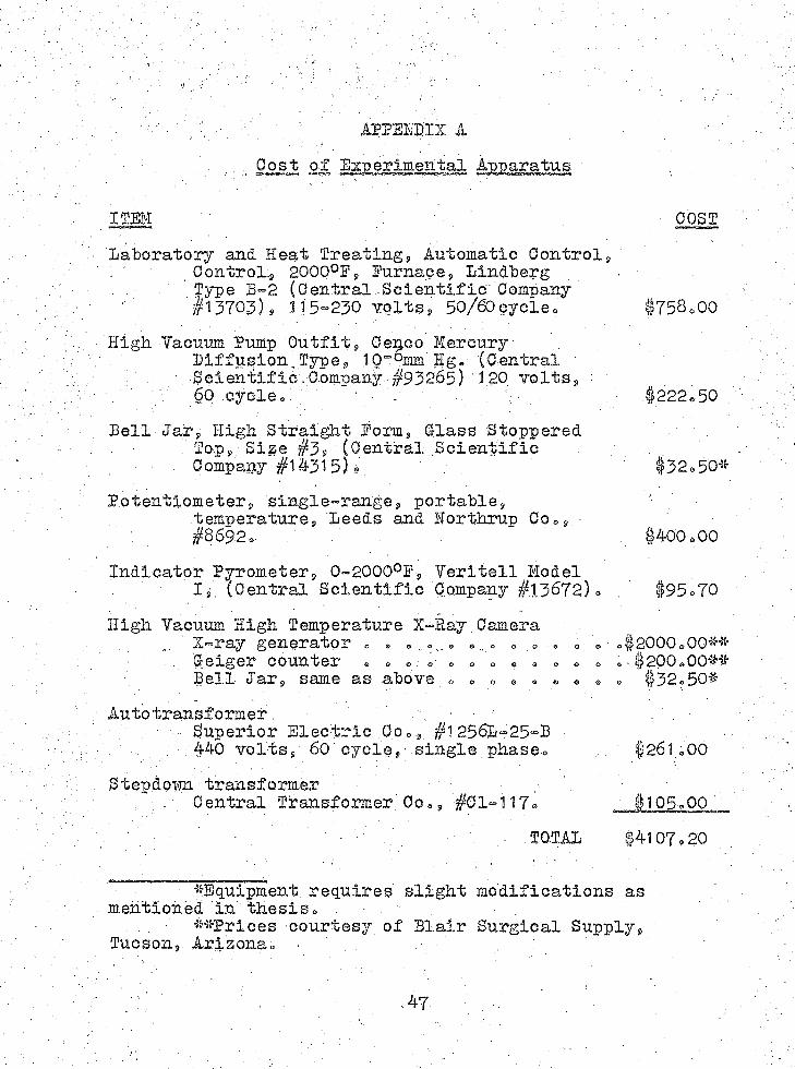
, : t ' APPEHSIX A ' -Post of Experimental Apparatus
I11M •' , V •.. OOSflaboratory and Heat Treating, Automatic Control,\ Control., 2G00°F, furnace, Mndberg, Type B“2 (Central..Scientific' Company' I1 3 7 0 3 ) , 115“230 Yolts, 50/60cycle. . #758.00
High Vacuum Pump Outfit, Ce^co Mercury.Piffusion^Type,. 10"omm' Hge (Central ' '
" ■ Scientific . Company #932.65) ' 120 volts, ■60 cycle« } , ... , ’ #222.50
Bell;Jar, High Straight Form,'Class Stoppered / '- Top, Size #3/ (Oertral .Scientific - ..
, Company #1#315)/. #32,50*Potentiometer, single-range, portable, '
temperature, Beeds and Horthrup Co.,.#8 6 9 2 ,. . #400,00
Indicator Pyrometer, 0“2000°F, Veritell ModelIs. (Central Scientific Company # 1.3 6 7 2 ) o . #95<=70
High Vacuum High Temperature X-Ray Camera .. X=ray generator , ,#2000.00**
C-eiger counter .*.• , » = , , , , „ 6 , ,. #200.00**Bell Jar, same as above > • ;» • . • ® , ., #32 = 50*
Auto transformer. . ■; ' 'Superior Electric Co., #12561-25-B . _ .
volts, 60 cycie,' single phase. #261,00Step.doim transformer
. ' Central Transformer.' Co,, #01 =>117, #105,00Vv • ' . . : . , TOTAL #4107.20
*Eguipment requires slight modifications as mentioned in thesiso
**Prices -courtesy of Blair Surgical Supply, Tucson, Arizonao ■
47

' a p p m b i x b ' . :' Samule .Density Oaleulations
'The crystal siruolmrea^ the lattice parameters must,"be Jfcnown these calculations« The crystalstructure and. the lattice parameters may be determined byuse of the X^ray diffraction approach (19) o
/. 'Example:' Givens Crystal structure ~ BOO.: ' f ' Dattloe parameter = 2*86 A0 . '
■ - V " r : Substahce ' IronDensity =: weight/unit cell ' = . ■ , ;
' ; volraie/unlt”cell h■ • ■ A'v -' /'v ' number' of atoms/unit cell % weight per atom
, ' lattice parameter (edge)
y Since there'are 2 atoms/unit cell in the BOO structures, and the weight per atom is; 55o84 gm/6o02z1G2 atoms/the weight, per unit cell is:
; ■ weight/unit cell - 2(55o84/6o02x1025) 0
. ,$he volume/unit .cell is just the cube of the lattice parameter or 1 " . .. ■ •., y
//;-.gi:yoltme/imit cell .-s-(2f86xtor®cm.)?e
'.therefore:'%/ % ' / , : , , ■ -,. - D e n s i t y =2(55.84/6„02x 1023)/(2.86x 10"8)3= ■
- V : 7.9m/cm3 i

APP11DIX O '. Availability of Experimental Apparatus
University of Arizona
Equipment LocationFurnace Assembly MetallurgyHigh. Vacuum Equipment Mechanical Engo
. Metallurgy Physics
Bell Jar and Chemistryassociated glass Physicsrequirementso
Sensing Equipment Mechanical Eng®Physics
X-ray generating Ceolo^runit® Metallurgy
PhysicsGeiger counter Geology
PhysicsTransformers Electrical Eng®
at the
AvailablltyFairPoor (in use)FairFairFairFair
GoodFairPoor (in use).FairFairPoor (in use) FairPoor (only
220)
49
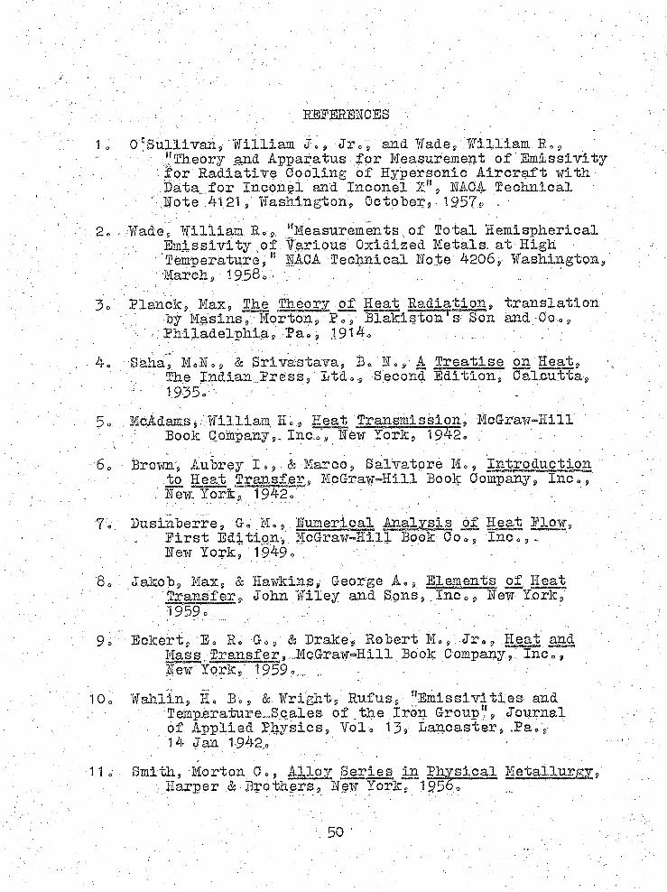
M B K M C ES
1* : William J., Jr*, and. Wade, 'William E,,• ■ • ^ “Theory and Apparatus for Heasurement of Emt-ssiYity• ■■ S'or Radiatiye Gooling of Hypersonic Aircraf t with
Data,;for Inconel and Inconel %", EAGA Technical : ■ Hote 41 21, Washington, October^ 1957= . \
;2. . Wade» William. Ro.s,. “Measurements of Total Hemispherical Emissivitynf Tarious, Oxidized Metals, at High
' ’ Temperature ? t! HAOA Technical Hote 4206,: Washington9: : . ' ; "' 'Marchs' 1958® - ; .. : '* ,
3o Planchs; Max9 The Theory of Heat Radiation, translationby Mas ins, Morton, Da, Blakiston s- Son and. Go,»,
v’t y; Philadelphia, /Pa»»: 1914,«. ; „ ; ;, 4„ Saha, Mol., & Srivastava, Be He,- A Treatise on Heat,
The indiah Press,’ Dtdo., Second Edition, Oalcutta, ■' ■ r'- 1.935o:'' ; ■ -.:V' -v:vS A;4 ■ ; • ■■ ■ . '
■ 5o . Mdidams,/.William H 0;,: Heat Transmission, McGraw-Hill ■ t Book OompanyInc.o, HeifTork, 1942« , "r
6c BrownV Aubrey, I . & Marco, Salvatore M,, Introduction- to Heat Transfer, McGraw°Hlll Book Company, Inc«,,'.
t. . ; : Hew Tork% 1942.: m "7= Dusinberre. 6. M. v:. numerical Analysis of Heat Plow,
. ... Pirst Editiqn$, McGraw-Hill Book G o I n c . , Hew lork^ 1949. : ' \ , ' ' 7 '
8.: iakob. Max, & Hawkins, George A,, Elements of Heat ■ 'Transfer.,. John Wiley and Sons,.Inc., Hew York,1959. ' V .. .• f. ;rV. " ■■
95 Eckert, E. R, E»,; & Drake, Robert M« ,: Jr®, Heat and Mass Transfer,...McGraw-Hill Book Company,:. Inc., lew tork,5 1 9 5 9 V . - .
10. Wahlin, H, B., & Wright, Rufus, “Emi s sivi ties and :Eemp.erature..-Scales of ..the -Iron Group.l', Journal of Applied Physics, TolV 13, Lancaster, .Pa.v
. i4 Jan 1942. - ' ; "11 . Smith, Morton C», Alloy Series in Physical Metallurgy,'
. Harper & Brothers, Hew York, " 1 9 5 6 0 “ 7
50

51
:;1 2® Smith's, Morton 0,» Principles of Physical Metallurgy® . Harder & Brothers, lew York, 19567
-13® WahliHg Hi B. and Knop s Harry, if ®» «Tr»9 “fhe Speetrhl : Bmissivity of Iron and. Gobalt," Physical Eeview, folo 74, lumber 69 p«,687=689, lew York, :15 Sep 19480
.14® Khops, Harry ¥», Jr® ? "Bmissivity of Alloys," Physical . EevieWj, Yol® 74, lumber 10/p® 1416, lew'-York,
' ■ 15 Ipy 1g4B0 ■ ; . ; : . ' , . ' .15® : Wahlin, H.®: 3. r "personal'Better to Robert D® Resley, " :
, Maciison,-; Win .$ Hov 196J,o: ..16®' Mnrphy, Da J®, "Study of Structure and Behavior of
.Copper and Brass by Precision Z~ray and . ' Hydrostatic. Determinations of Density," Pitman-
i)unn Laboratories Department, Prankford Arsenal, Philadelphia, Pa® , ,May -1952®. . / = '
17>', 'Maykuth,• D® A®, Ogden,. H®‘ R®, and jaffee, H® I®,"The Bffects.of Alloying Blements in Titanium,
‘ ■ folume A, Constitution, Defense Metals Information Center, Report 3$ Columbus.,. Ohio,. 15 Sep
' ' I960®. : ' ,■ . : ■ ■■' ■18® Hatf, B® A® 9 Kent, P® J® C., and Williams, 0. I® ,
, "High Yaouum High Temperature,..X-ray Camera."p■ Journal of Scientific Instruments, Yol® 37sDo 273s London, Bngland, I960®
19® Yan Ylaok® Lawrence H®, Blemehts of MaterialsScience,.Addison-Wesley'Publishing Co®, Inc®,
: i Heading, 'Hass® , 19.59, p® 58. ... .20® Ouliity, BY, Do s Blemehts of X-ray Diffraction,' Addison^W.esley Publishing.OOo, Inc., Reading,■ ’ ' lass® , 1;956® ' ■ : : / , ,
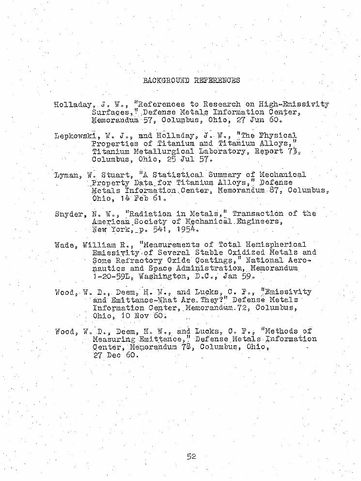
BACKGROUND RBBBHSNCSB
S o l l a d a y ' , , “References to Research on High-Emissivity . Surfaces^.-Defense; Metals Information Center, ■ ; .Memorandnm 57$ 0oiiimbus9 Ohio, 27 Jun 60e
Depkowski, ¥«, Jo $ and .Holladay, Jo,AL $ ”lhe Physical Properties of .litanium and Titanium Alloys, “ Titanium Metallurgical Lahoratory, Report 73$ Columbus, Ohio, 25 Jul 57 = '
' Lymari, Vo Stuart, “A Statistical Summary of Mechanical. ..Property Data..for Titanium Alloys,‘f Defense
Metals Information,Center, Memorandum.8 7 , Columbus,. Ohio, 1A Feb 61» , ■
Snyder, Ho Vo, “Radiation in Metals," Transaction of the . American,Society of Mechanical.Engineers, lew Iork,,..po 541, 1 9 5 4 0 . ; .... ■ .
Wade, Villiam Bo, “Measurements of Total HemisphericalEmissiyity-of Several Stable Oxidized Metals and Some Refractory Oxide Coatings,11 Rational Aeronautics and Space Administration, .Memorandum 1=,20-591, Washington, DoCo, Jan 59 m .
Wood, Wo Do, Deem,' R>; We ,; and Ducks, C* F., “Emissivity ' : and Emlttance-What Are: They?" Defense Metals •
Information Center,.Memorandum.72, Columbus,■ Ohio, 10 Hov 60o , :
Wood, Wo D., Deem, R. Wo, and lucks, Co F®, "Methods of ; - Measuring Emittance," Defense,.Metals-Information
Center, Memorandum 7®,.Columbus, Ohio,27 Dec 60, . „ " -
52