missouri river wastewater treatment plant - maryland heights
TRANSCRIPT

SANDIA REPORT
SAND2006-3522 Unlimited Release Printed June, 2006 Fusion Transmutation of Waste and the Role of the In-Zinerator in the Nuclear Fuel Cycle
B.B. Cipiti
Prepared by Sandia National Laboratories Albuquerque, New Mexico 87185 and Livermore, California 94550 Sandia is a multiprogram laboratory operated by Sandia Corporation, a Lockheed Martin Company, for the United States Department of Energy’s National Nuclear Security Administration under Contract DE-AC04-94AL85000. Approved for public release; further dissemination unlimited.

Issued by Sandia National Laboratories, operated for the United States Department of Energy by Sandia Corporation.
NOTICE: This report was prepared as an account of work sponsored by an agency of the United States Government. Neither the United States Government, nor any agency thereof, nor any of their employees, nor any of their contractors, subcontractors, or their employees, make any warranty, express or implied, or assume any legal liability or responsibility for the accuracy, completeness, or usefulness of any information, apparatus, product, or process disclosed, or represent that its use would not infringe privately owned rights. Reference herein to any specific commercial product, process, or service by trade name, trademark, manufacturer, or otherwise, does not necessarily constitute or imply its endorsement, recommendation, or favoring by the United States Government, any agency thereof, or any of their contractors or subcontractors. The views and opinions expressed herein do not necessarily state or reflect those of the United States Government, any agency thereof, or any of their contractors. Printed in the United States of America. This report has been reproduced directly from the best available copy. Available to DOE and DOE contractors from
U.S. Department of Energy Office of Scientific and Technical Information P.O. Box 62 Oak Ridge, TN 37831 Telephone: (865)576-8401 Facsimile: (865)576-5728 E-Mail: [email protected] Online ordering: http://www.osti.gov/bridge
Available to the public from
U.S. Department of Commerce National Technical Information Service 5285 Port Royal Rd Springfield, VA 22161 Telephone: (800)553-6847 Facsimile: (703)605-6900 E-Mail: [email protected] Online order: http://www.ntis.gov/help/ordermethods.asp?loc=7-4-0#online
2

3
SAND2006-3522 Unlimited Release Printed June, 2006
Fusion Transmutation of Waste and the Role of the In-Zinerator in the Nuclear Fuel Cycle
B.B. Cipiti
Nuclear and Risk Technologies Sandia National Laboratories
P.O. Box 5800 Albuquerque, NM 87185-0748
Abstract The Z-Pinch fusion experiment at Sandia National Laboratories has been making significant progress in developing a high-energy fusion neutron source. This source has the potential to be used for the transmutation of nuclear waste. The goal of this research was to do a scoping-level design of a fusion-based transmuter to determine potential transmutation rates along with the fusion yield requirements. Two “In-Zinerator” designs have been developed to transmute the long-lived actinides that dominate the heat production in spent fuel. The first design burns up all transuranics (TRU) in spent fuel (Np, Pu, Am, Cm), and the second is focused only on burning up Am and Cm. The TRU In-Zinerator is designed for a fuel cycle requiring burners to get rid of all the TRU with no light water reactor (LWR) recycle. The Am/Cm In-Zinerator is designed for a fuel cycle with Np/Pu recycling in LWRs. Both types of In-Zinerators operate with a moderate fusion source driving a sub-critical actinide blanket. The neutron multiplication is 30, so a great deal of energy is produced in the blanket. With the design goal of generating 3,000 MWth, about 1,200 kg/yr of actinides can be destroyed in each In-Zinerator. Each TRU In-Zinerator will require a 20 MW fusion source, and it will take a total of 20 units (each producing 3,000 MWth) to burn up the TRU as fast as the current LWR fleet can produce it. Each Am/Cm In-Zinerator will require a 24 MW fusion source, and it will take a total of 2 units to burn up the Am/Cm as fast as the current LWR fleet can produce it. The necessary fusion yield could be achieved using a 200-240 MJ target fired once every 10 seconds.

4
Acknowledgement The author would like to thank JD Smith, John Kelly, and Gary Rochau for their guidance in the research. Paul Wilson, Laila El-Guebaly, and Phiphat Phruksarojanakun from the University of Wisconsin along with Pavel Tsvetkov and Avery Guild-Bingham from Texas A&M provided a great deal of help in the model development.

5
Acronyms Elements Am Americium Bk Berkelium Cf Californium Cm Curium Cs Cesium I Iodine Np Neptunium Pu Plutonium Sr Strontium Tc Technetium U Uranium D-T Deuterium-Tritium LiF Lithium Fluoride Acronyms ADS Accelerator Driven Systems AFCI Advanced Fuel Cycle Initiative FR Fast Reactor GNEP Global Nuclear Energy Partnership HLW High Level Waste LLW Low Level Waste LWR Light Water Reactor MOX Mixed Oxide Fuel MT Metric Ton MTIHM Metric Ton of Initial Heavy Metal MWD Mega-Watt Day TRU Transuranic Isotopes (Np, Pu, Am, Cm) UREX Uranium Extraction (Aqueous Processing of Spent Fuel)

6
Fusion Transmutation of Waste and the Role of the In-Zinerator in the Nuclear Fuel Cycle
Introduction The challenge of building an advanced nuclear fuel cycle is one that must be accomplished in the coming decades. It is clear that nuclear power is the only way to produce competitive, emission-free power on a large-scale; however, the infrastructure still needs to be developed to recycle and minimize the amount of nuclear waste produced. The Yucca Mountain Project has proven how difficult it is to develop an acceptable repository, yet the capacity is only enough to take spent fuel produced from the commercial fleet of reactors through the year 2015. Reprocessing and transmutation technologies have the ability to drastically decrease the heat load and radiotoxicity of high level waste destined for the repository, such that one repository is all that will be needed for a couple of centuries. Transmutation of actinides is required to reach this goal, and Z-pinch fusion may provide an attractive option for burning up these species. The Z-Pinch fusion experiment at Sandia National Laboratories uses an intense pulsed power source to ignite a D-T fusion target. While the facility is currently equipped to fire a shot once per day, research has looked at how to develop the concept into a power plant capable of multiple shots per minute.1 The high-energy neutrons produced from the shot can be used to fission actinides for waste reduction with a relatively modest fusion yield requirement. Therefore, transmutation of waste may provide fusion with an intermediate goal before the development of a pure fusion power plant. The goal of this work was to do a high-level scoping analysis of waste reduction goals and how Z-Pinch driven fusion transmutation may fit into the nuclear fuel cycle. In addition, a preliminary design for this ‘In-Zinerator’ concept is discussed along with the calculated transmutation rates and fusion yield requirements. In-Zinerator Concept The Z-Pinch concept uses an intense pulsed power source to implode a tungsten wire array surrounding a D-T fusion target (see Figure 1). The rapid power delivery generates an intense x-ray source that heats and compresses the target to the energies and densities required to initiate fusion. Transmission lines are attached to the top and bottom of the holhraum to deliver the energy pulse through the wires. When the fusion reaction is ignited, the result is the production of a point source of 14.7 MeV D-T neutrons. A key engineering challenge (outside the scope of this work) in using the fusion neutrons for transmutation is to ignite a fusion target every ten seconds. The fusion yield will destroy the lower part of the transmission line, so a recyclable transmission line will need to be developed to reach a high shot rate. The goal of this work was to design a sub-critical transmutation blanket, which surrounds the target chamber, to capture most of the neutrons produced. The fusion neutrons initiate a fission burn of the actinides with a neutron multiplication near 30, so the bulk

7
of the power is produced in the blanket. Ultimately, this design is a hybrid reactor with a 30 MW fusion source driving a 3,000 MW actinide blanket.
Figure 1: Z-Pinch Wire Array and Target Figure 2 shows a picture of what an In-Zinerator power plant might look like. The pulse for the fusion target is driven by a Linear Transformer Driver, a series of capacitor banks that can deliver 10s of MJ pulses on a short (<100 ns) time frame. The fusion target has a yield around 300 MJ for a shot rate once every ten seconds. The fusion neutrons drive a sub-critical blanket containing the actinides in a cylindrical geometry. A secondary lead coolant circulating through pipes within the actinide blanket removes the heat to drive the power plant. The actinide loop is continuously circulated at a slow rate to remove fission products and tritium. There are numerous engineering challenges associated with the design of this system, but these are outside the scope of this work. Many of these issues have been examined in the work on developing a Z-Pinch Power Plant1 and will continue to be investigated in the future.
Figure 2: In-Zinerator Power Plant
The actinide mixture is in a fluid form during operation. The use of a fluid fuel eliminates the need for solid fuel fabrication and allows for continuous processing of the fluid to remove fission
Tungsten Wires
D-T Target Hohlraum

8
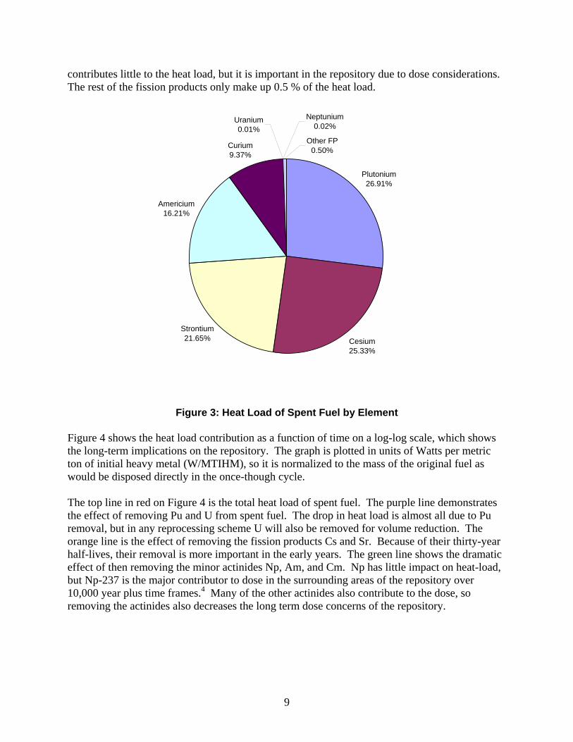
products and add actinides to maintain constant inventories. The actinide mixture was difficult to choose and may yet change depending on engineering issues. The difficulty was in choosing a material with a reasonable operating temperature and high solubility for actinides. LiF was chosen for a number of reasons. LiF is theorized to form a eutectic with AcF3 at 33 mole% actinide fluoride—this eutectic is liquid at 675 ºC.2 The lithium was required to be able to breed tritium to sustain the fusion reaction. There is a great deal of uncertainty surrounding this material choice, so experimental work will be required in the future. The fissioning of the actinides will produce fission products which eventually need to be removed from the coolant. It may be possible to create molten salt centrifugal contactors to separate fission products from the actinides in a steady-state manner. This topic will also be a subject of research in the future. Before the design of the actinide blanket can be discussed, it is important to understand what the transmutation goals are and how this In-Zinerator could fit into the nuclear fuel cycle. The next section discusses these issues that drive the blanket design. The Nuclear Fuel Cycle Spent Nuclear Fuel The current U.S. light water reactor (LWR) fleet consists of 104 reactors producing about 100 GWe. It is likely that if new nuclear reactors are built in the U.S., they will be of the advanced LWR class, with costs similar to today’s reactors but with advanced safety features. Currently, the U.S. LWR fleet produces about 2,000 MT of spent nuclear fuel per year. The Yucca Mountain Project has examined the direct disposal of this accumulated spent fuel. The repository is designed to hold 70,000 MT of spent fuel and other high level wastes (HLW) with 63,000 MT making up commercial spent fuel.3 About 45,000 MT of spent fuel has been accumulated to date, so in about 10 years, the repository will already be full which will require additional repositories and inhibit future growth in nuclear power. The repository is not limited by space, but rather by the heat load and radiotoxicity of the fuel.4 The heat load determines how closely the waste can be packed without causing changes in water flow in the surrounding rock, but the radiotoxicity and mobility of isotopes are also important since they affect long-term dose rates. Currently, the repository is limited by temperature, so a reduction in heat load means more waste can go into the repository. The Advanced Fuel Cycle Initiative (AFCI) has done extensive research on alternative fuel cycles that extend the capacity of the repository. Figure 3 shows the heat load contribution of the various species in 50-year-old spent fuel. This data is representative of pressurized water reactor fuel with a burnup of 60,000 MWD/MT and initial enrichment of 4.03 %. The dominant heat producers are Pu, followed by the fission products Cs/Sr, followed by the minor actinides Am/Cm. Although U makes up the majority of the mass of spent fuel, it has a very small contribution to heat load. Np is a minor actinide that
9
contributes little to the heat load, but it is important in the repository due to dose considerations. The rest of the fission products only make up 0.5 % of the heat load.
Plutonium26.91%
Cesium25.33%
Curium9.37%
Neptunium0.02%
Uranium0.01%
Other FP0.50%
Americium16.21%
Strontium21.65%
Figure 3: Heat Load of Spent Fuel by Element
Figure 4 shows the heat load contribution as a function of time on a log-log scale, which shows the long-term implications on the repository. The graph is plotted in units of Watts per metric ton of initial heavy metal (W/MTIHM), so it is normalized to the mass of the original fuel as would be disposed directly in the once-though cycle. The top line in red on Figure 4 is the total heat load of spent fuel. The purple line demonstrates the effect of removing Pu and U from spent fuel. The drop in heat load is almost all due to Pu removal, but in any reprocessing scheme U will also be removed for volume reduction. The orange line is the effect of removing the fission products Cs and Sr. Because of their thirty-year half-lives, their removal is more important in the early years. The green line shows the dramatic effect of then removing the minor actinides Np, Am, and Cm. Np has little impact on heat-load, but Np-237 is the major contributor to dose in the surrounding areas of the repository over 10,000 year plus time frames.4 Many of the other actinides also contribute to the dose, so removing the actinides also decreases the long term dose concerns of the repository.

10
Heat Load Contributors in Spent Fuel
1.0E-02
1.0E-01
1.0E+00
1.0E+01
1.0E+02
1.0E+03
10 100 1000 10000 100000
Time (Years)
Hea
t Loa
d (W
/MTI
HM
)
Figure 4: Heat Load of Spent Fuel as a Function of Time
This graph demonstrates which elements are important to remove in an advanced reprocessing plant. Uranium is extracted as a strategic resource and to reduce volume. Pu, also a strategic resource and proliferation concern, and the other minor actinides (Np, Am, Cm) are extracted due to their long-term contribution to heat load and dose. Cs and Sr are extracted due to their short-term contribution to heat load. All of these separations have the potential to decrease the heat load by a factor of 100 at the time of emplacement and a factor of 1,000 after 100 years depending on separation efficiency. This could mean that based on the thermal limits, the repository could hold the reprocessed waste from 100 times as much fuel as with the direct disposal plan. Reprocessing The UREX+ reprocessing concept has been studied by the AFCI program extensively for the purpose of improving waste management. The basic UREX reprocessing concept removes uranium from spent fuel, but other separations steps can be added to remove other elements of interest. The additional separation steps are designed to remove the major contributors to the heat load. The UREX+1a scheme has a separation step for U, Cs/Sr, and all the TRU (Pu, Np, Am, Cm). One of the major reasons for choosing group extraction of the TRU is so that pure Pu is not separated (to address proliferation concerns). It should be noted that there is debate surrounding
SNF Direct Disposal SNF w/o U,Pu
SNF w/o U,Pu,Cs,Sr
SNF w/o U,Pu,Cs,Sr,Np,Am,Cm

11
this rational. It would be easy to modify a UREX+ scheme to separate pure Pu, and it is questionable how much proliferation resistance is added by keeping the Np/Am/Cm in with the Pu. It is also questionable why reprocessed fuel would be used for making weapons when there are easier ways to obtain fissionable material. This topic will likely be explored in more detail, as it would be un-wise to model a new fuel cycle around this limitation without a strong argument. Additional processing steps have been investigated to separate Am/Cm from the Pu/Np in the TRU, and even isolation of specific species. However, the current Global Nuclear Energy Partnership is focusing on the UREX+1a process.5 Figure 5 shows a simplified flow diagram of UREX+1a showing all of the different product and waste streams generated.
Figure 5: UREX+1a Reprocessing6,7 The two major product streams are U3O8 (which could be stored for re-enrichment, or perhaps future breeding, or disposed as low level waste) and the TRU oxide (which could be stored for future use as fast reactor fuel or as fuel for other potential burners). There are five major waste streams in addition to small amounts of low level waste that are produced: I, Tc, hulls, vitrified fission products, and Cs/Sr. The short-lived isotopes of Cs/Sr are placed into a solid waste form and could go to a temporary waste storage facility for natural decay. The hulls consist of the zirconium fuel cladding and all of the support structures in the assembly. Unless the hulls can be cleaned to a high level of decontamination, they will have to go to the repository. However, they contain little of the radioactive species so contribute little to the heat load of the waste. The vitrified fission products also are destined for the repository. Tc and I are two fission products that are separated as part of the UREX process—unless there are alternatives for these species, they will likely be collected and packaged for the repository.

12
The UREX+1a process is able to partition all of the major contributors to heat load and long term dose in spent fuel. This process must be in place in order to provide the fuels for fast-spectrum reactors or transmuters to transform long-lived species into safer or more stable forms. Transmutation The term ‘transmutation’ spans many nuclear processes, but the main goal is to turn a long-lived isotope into a short-lived or stable species. Transmutation of actinides refers to the fissioning or ‘burning’ of these species. Although fission produces a spectrum of radioactive fission products, the long-term radioactivity and heat load of the fission products is much less than the actinides, so there is a net gain to burning up actinides. In addition, due to the high energy content in the actinides, transmutation produces a great deal of power. Neutrons are used to initiate the fission reactions. When bombarded with a neutron, an actinide can either capture the neutron and create a heavier actinide, or it can absorb the neutron and fission. The trick with actinide fissioning is to operate at neutron energies such that fission occurs more often than capture. For Np, Am, and Cm, a high neutron energy (fast spectrum) is required to optimize this fission to capture probability.
Am-241 Fission and Capture Cross-Sections
0.001
0.01
0.1
1
10
100
1000
10000
100000
0.00001 0.001 0.1 10 1000 100000 10000000
Energy (eV)
Cro
ss-S
ectio
n (b
arns
)
fission
capture
Figure 6: Fission to Capture Cross-Section8 Figure 6 shows an example of the fission and capture cross-sections for Am-241. The capture cross-section is always higher until above 1 MeV neutron energy. This graph demonstrates the

13
value of moving to fast spectrums with neutron energies greater than 1 MeV for burning up the minor actinides. Many of the other actinides that build up in spent fuel show similar trends. There are three different methods for generating a fast neutron spectrum: fast reactors, fusion, and accelerator-driven systems. Fast Reactor (FR) deployment has been the preferred strategy for transmutation of actinides since they have been built in the past. Of the three transmutation options, FRs are at the highest level of technological readiness. There are some concerns about the safety of designing large power cores with liquid metal coolants, though these concerns may be similar for any transmutation scheme. The largest uncertainty with fast reactors is their efficiency for burning up actinides. Transmutation efficiency is measured as conversion ratio, and it depends on the amount of fertile material (depleted uranium) that is present in the fuel. More fertile material results in a lower overall transmutation rate due to capture and higher actinide build-up. It is hoped that a fast burner reactor could be designed with a conversion ratio of 0.5 or lower. AFCI research suggests that 0.25 may be the best that can be practically achieved.9,10 Lower conversion ratio reactor designs could be more expensive or require much longer development times. For the sake of this comparison, a conversion ratio of 0.25 will be assumed. This conversion ratio leads to a support ratio of 1 fast reactor for every 3 LWRs to balance TRU production with TRU destruction. Fusion transmutation uses a moderate fusion source to initiate fission in a sub-critical blanket containing actinides. The burning up of the actinides produces much more energy than the fusion source if a high neutron multiplication is designed. The disadvantage of fusion is that it is at a much lower technological readiness level than fast reactors, and likely a fusion transmuter will cost more than a fast reactor producing the same output power. The advantage is that a sub-critical blanket does not have the same safety and control issues as a fast reactor core, so the conversion ratio of a fusion transmuter can be 0. In other words, no fertile uranium is required in the actinide blanket, so the transmuter can operate in a ‘burn-only’ mode. The resulting support ratio is 1 fusion transmuter for every 4-5 LWRs to balance the TRU production rate, which possibly could result in fusion transmutation being more cost competitive in comparison to fast reactors. Accelerator-Driven Systems (ADS) use a GeV proton accelerator to create spallation neutrons from a (typically) lead target. The neutron source is strong enough to drive a sub-critical transmutation blanket similar to the fusion transmutation concept. ADS have received a fair amount of interest in the past,11 though recent efforts have slowed in the U.S. due to concerns over accelerator size, cost, technological readiness, but primarily because of their limitations to generate electricity as power plants. For the purpose of this report, only the fusion transmuter and fast reactor concepts will be compared. Advanced Fuel Cycle Scenarios Numerous fuel cycle scenarios have been studied in the past; however, only two scenarios will be discussed to compare the transmutation options. Scenario 1 involves transmuting all separated TRU in either FRs or In-Zinerators. Scenario 2 involves burning Pu/Np in the current fleet of LWRs and only burning Am/Cm in FRs or In-Zinerators.

14
Scenario 1 (TRU Burners) In Scenario 1, spent LWR fuel is reprocessed to pull out all TRU together. Scenario 1 can be broken down further into two possibilities. Scenario 1a uses FRs to burn up all the TRU, and Scenario 1b uses an alternative burner like fusion to burn down the TRU. The Global Nuclear Energy Partnership plan follows Scenario 1a. Figure 7 gives a pictorial view. In this scenario, LWR spent fuel is reprocessed, and TRU is pulled out as a group. The TRU is fabricated into fuel for a FR fleet. Figure 7 also includes the expected mass flows for the system per metric ton of reprocessed LWR fuel. A large, 2,000 MT/yr reprocessing plant produces about 24,600 kg TRU per year, so the burners in Scenario 1 should be designed to burn this much up per year. In addition to the technological readiness advantage, the use of FRs also plans for the future when Pu breeding may be needed in order to sustain the fuel cycle. If FRs are able to be built and operated at similar costs to LWRs, this plan probably makes the most sense. However, it is likely that initially FRs will cost more to build and operate than LWRs. It is expected that there will be numerous safety concerns with deploying a fleet of FRs utilizing liquid metal coolants. In addition, TRU fuel fabrication will be expensive since remote operation is required. At a conversion ratio of 0.25, about 33 FRs will be required to burn up the TRU as fast as the current fleet can produce it (given the current fleet of 100 LWRs).
Figure 7: Scenario 1a (GNEP Plan)5,7,12 Scenario 1b is an alternative that could be realized if fusion transmutation could replace FRs for TRU burning (see Figure 8). The In-Zinerator concept does not require fuel fabrication since the actinides are in a fluid form. The better support ratio is shown in the figure—the current LWR fleet would require about 20 In-Zinerators to balance the TRU production.
LWR FR UREX+1a Reprocessing
UOX Fab.
TRU Fab.
Pyro- Processing
HLW Disposal
LLW Disposal
75% of Nuclear Power Generation
U: 941 kg/MT Misc: 0.129 m3/MT
NOTE: All mass flows are per MT of reprocessed LWR fuel
HLW: 0.0881 m3/MT I: 0.00175 m3/MT Tc/Hulls: 306 kg/MT TRU: 0.000625 m3/MTCs/Sr: 0.0517 m3/MT
TRU: 18.3 kg/MT (oxide form)
DU: 67.8 kg/MT
FR Fuel: 86.1 kg/MT
HLW: 0.0441 m3/MT I: 0.000875 m3/MT Tc/Hulls: 153 kg/MT Cs/Sr: 0.0259 m3/MT
25% of Nuclear Power Generation

15
Fusion transmutation of waste is at an immature point in technological readiness, and likely such a unit would be more expensive than a FR. However, due to the better support ratio and the elimination of fuel fabrication, there could be some overall cost benefit to the In-Zinerator concept.
Figure 8: Scenario 1b5,7,12 Scenario 2 (Am/Cm Burners) Scenario 2 requires much less infrastructure to achieve the same goals as Scenario 1. In Scenario 2, Pu and possibly Np are sent back to the current LWR fleet as mixed oxide (MOX) fuel. It may be possible to use the existing LWR fleet to burn down the Pu produced, but it would require extensive MOX fuel fabrication and core loading.13 The advantage is that the LWRs are already in operation, and MOX as a fully developed technology is believed to have an almost negligible impact on cost of electricity. Thermal reactors, though, cannot be used to burn down the other minor actinides, so a dedicated burner could be used just for that purpose. Scenario 2a uses fast reactors to burn down the Am/Cm (see Figure 9). A 2,000 MT/yr reprocessing plant produces about 2,400 kg/yr of Am/Cm. Because there is so much less Am/Cm as compared to Pu, this scenario requires much fewer FRs than in Scenario 1a. The support ratio is about 1 FR for every 30 LWRs. Unfortunately, less research has been done on the design of a FR that is fueled with only Am/Cm. The heat load of an Am/Cm fuel rod would be high enough to cause significant problems with fuel fabrication and fuel handling, so there may be a limit to the loading that is possible with this scenario.13 More research is required on this topic.
LWR In-ZineratorUREX+1a Reprocessing
UOX Fab.
Pyro- Processing
HLW Disposal
LLW Disposal
83% of Nuclear Power Generation
17% of Nuclear Power Generation
U: 941 kg/MT Misc: 0.129 m3/MT
NOTE: All mass flows are per MT of reprocessed LWR fuel
HLW: 0.0881 m3/MT Hulls: 305 kg/MT TRU: 0.000625 m3/MTCs/Sr: 0.0517 m3/MT
TRU: 12.6 kg/MT (metal form)
HLW: 0.022 m3/MT Cs/Sr: 0.013 m3/MT

16
Figure 9: Scenario 2a5,7,12
The disadvantage of MOX burning in LWRs is that it is not indefinite. MOX fuel will have a buildup of some even isotopes of Pu that cannot be burned up in LWRs. In addition, this buildup causes core control problems after 2 or 3 recycles.13 Therefore, MOX burning is in some ways a temporary solution. On the other hand, 2 or 3 recycles gives us an additional 100 years or so to develop permanent solutions while at the same time extracting useful energy. Finally, Scenario 2b replaces the FRs with In-Zinerators (see Figure 10). Due to the better conversion ratio, the support ratio is 1 In-Zinerator for every 50 LWRs. In other words, the current U.S. LWR fleet would only need 2 Am/Cm In-Zinerators to burn up the Am/Cm as fast as it is produced.
Figure 10: Scenario 2b5,7,12
LWR FR UREX+1a Reprocessing
UOX Fab.
TRU Fab.
Pyro- Processing
HLW Disposal
LLW Disposal
97% of Nuclear Power Generation
3% of Nuclear Power Generation
U: 787 kg/MT Misc: 0.129 m3/MT
NOTE: All mass flows are per MT of reprocessed LWR fuel
HLW: 0.0881 m3/MT I: 0.00175 m3/MT Tc/Hulls: 306 kg/MT TRU: 0.000625 m3/MT Cs/Sr: 0.0517 m3/MT
MA: 2.9 kg/MT (oxide form)
DU: 10.7 kg/MT
FR Fuel: 13.6 kg/MT
HLW: 0.0052 m3/MT I: 0.000106 m3/MT Tc/Hulls: 18.4 kg/MT Cs/Sr: 0.0031 m3/MT
MOX Fab.
Pu: 15.4 kg/MT U: 154 kg/MT (oxide form)
LWR In-ZineratorUREX+1a Reprocessing
UOX Fab.
Pyro- Processing
HLW Disposal
LLW Disposal
98% of Nuclear Power Generation
2% of Nuclear Power Generation
U: 787 kg/MT Misc: 0.129 m3/MT
NOTE: All mass flows are per MT of reprocessed LWR fuel
HLW: 0.0881 m3/MT Hulls: 305 kg/MT TRU: 0.000625 m3/MT Cs/Sr: 0.0517 m3/MT
MA: 1.95 kg/MT (metal form)
HLW: 0.0026 m3/MT Cs/Sr: 0.00155 m3/MT
MOX Fab.
Pu: 15.4 kg/MT U: 154 kg/MT (oxide form)
17
In moving through the scenarios, each one has become progressively easier in terms of new infrastructure required. A very real drawback to complete TRU burning, is that it requires many units. Whether the technology is a FR or the In-Zinerator, these designs will be technologically complex and new. It is likely that they all will have safety and licensing concerns. Also, any additional increase in commercial nuclear power generation in the coming decades will most likely be in the form of an advanced LWR design. If the U.S. is going to move to an advanced fuel cycle, it would be much more realistic to build one or two burners as opposed to an entire fleet. Scenario 2 allows for this option. Then, after a number of years of operational experience and optimization, the country will be in a much better position to plan to build additional units depending on the fuel cycle needs. All four scenarios can achieve the same waste reduction goals in the next century. MOX burning will eventually lead to buildup isotopes that have to be burned up in a fast spectrum, but there may also be long-term buildup isotopes in FRs. The only way to burn up all of these species is to increase the neutron energy, and this can only be done with fusion. Note that the FR plan and the In-Zinerator plan both give alternative energy options in the future. FRs can lead to sustainable energy growth through the use of Pu breeding. The In-Zinerator could lead to hybrid reactor designs and eventually fusion energy given more research and development. Modeling Methodology There are two fusion transmuter designs that were developed: the Am/Cm In-Zinerator and the TRU In-Zinerator. Both concepts have a similar look, but the dimensions are slightly different to account for the differences in isotopic ratios. The goal was to find a geometry for the actinide blanket that kept the blanket sub-critical with a neutron multiplication near 30 throughout the life of the reactor. The initial chamber design is shown in Figure 11. The standoff from the target to the first wall is 1.5 m, and the blanket is 4 m tall. The chamber wall is modeled as 5 cm thick steel. The blanket thickness is 50 cm for the Am/Cm In-Zinerator and 40 cm for the TRU In-Zinerator. The lead coolant channels are 6 cm for the Am/Cm In-Zinerator and 8 cm for the TRU In-Zinerator. The TRU In-Zinerator has a slightly less overall actinide mixture volume due fact that Pu fissions more readily than Am/Cm. A lead reflector surrounding the blanket helps to increase the multiplication. The lead coolant was designed to be separate from the actinide mixture so that the rest of the plant is not contaminated with actinides and fission products. The coolant channels are thick enough to allow for robust welds at the top and bottom—any mixing of the coolants would be a problem.

18
Figure 11: In-Zinerator Chamber MCNP5.0 was used to determine the neutron multiplication and total transmutation rates for all actinides in the blanket. The total loss for each isotope was calculated using the sum of all fission and (n,x) reactions. Then the total gain was calculated by considering the reactions (n,2n), (n,nd), (n,d), (n,γ), and (n,α) on all of the actinides. Table 1 lists the isotopes that are tracked in the code and the reactions that can occur to produce a gain. For example, Np-237 can be produced by two reactions in the blanket. One reaction is Pu-239(n,nd)Np-237, and the other reaction is Np-236(n,γ)Np-237. The other reactions are not possible since the parent does not exist in the blanket. The list in Table 1 includes all isotopes of significant-enough quantities to be considered and does not include isotopes with very short half-lives. There are other subtle pathways that were included in the gain or loss of a particular isotope. The decay of isotopes was considered for those isotopes with relatively short half-lives. For example Pu-241 has a half-life of 14.35 years, so its decay to Am-241 must be taken into account over the life of the transmuter. In addition, there are several examples where a nuclear reaction produces a short-lived species that decays into another actinide. These reaction paths were all included. For example, the neutron capture of Pu-242 produces Pu-243 which has a 5 hour half-life. This in turn decays into Am-243. For the purposes of the model, it was assumed that the capture of Pu-242 leads to the production of Am-243. Once the total gain or loss for each isotope was calculated, MatLab was used to then modify the isotope inventories within the blanket. The total loss of all actinides was used to determine how much refueling was required. The isotope ratios were modified, and MCNP was run again. A loop was set up in MatLab to automate this process and track the change in isotopics with time. This also tracked the change in neutron multiplication with time as the ratios changed. The following sections present the results of the two transmuter designs.
1.5 m
4 m Lead Coolant
Channels
ActinideBlanket
5 cm Steel Wall
Lead Reflector

19
Isotope Total Fission + Total Capture (n,2n) (n,nd) (n,d) (n,γ) (n,α)
Np-236 x x Np-237 x x x Pu-238 x x Pu-239 x x x x x Pu-240 x x x x x x Pu-241 x x x x x x Pu-242 x x x x Pu-244 x x Am-241 x x x x
Am-242m x x x x x Am-243 x x x x Cm-242 x x Cm-243 x x x Cm-244 x x x Cm-245 x x x Cm-246 x x x x Cm-247 x x x x x Cm-248 x x x Bk-249 x x Cf-249 x x Cf-250 x x
Table 1: MCNP Reactions
Results Am/Cm In-Zinerator The first design investigated was the Am/Cm In-Zinerator, which fits into fuel cycle Scenario 2b. Fueling with only Am/Cm produces some Pu isotopes over time due to the numerous reaction and decay paths. This ratio change was enough to cause an increase in multiplication over many months. One way to help solve this problem was to initially dope the blanket with a small quantity of the Pu/Np from the reprocessing plant. The Pu was placed in the blanket in ratios similar to where the Am/Cm burner reached equilibrium. This modification kept the multiplication close to constant throughout the life of the reactor. Reflectors were used in the design to fine tune the multiplication to the desired power level. Table 2 shows the initial loading (in percent of total actinides) along with the refueling ratios. Note that refueling was accomplished with only the Am/Cm isotopes. The initial doping with Np/Pu is equal to 1/15th of the actual amount going through a reprocessing plant. During the model runs, the total transmutation rate for one time step was used to determine how much total refueling was required. The ratios shown in Table 2 were used to then figure out how much of each individual isotope to add at the end of the time step.

20
Isotope Initial Loading Refueling
Np-236 2.79E-08 0 Np-237 2.80E-02 0 Pu-238 1.02E-02 0 Pu-239 1.73E-01 0 Pu-240 1.00E-01 0 Pu-241 3.51E-03 0 Pu-242 2.19E-02 0 Pu-244 4.21E-06 0 Am-241 5.26E-01 7.94E-01
Am-242m 9.32E-04 1.41E-03 Am-243 1.17E-01 1.77E-01 Cm-242 2.25E-06 3.40E-06 Cm-243 1.58E-04 2.38E-04 Cm-244 1.21E-02 1.82E-02 Cm-245 4.94E-03 7.45E-03 Cm-246 1.11E-03 1.67E-03 Cm-247 2.13E-05 3.21E-05 Cm-248 2.45E-06 3.69E-06 Bk-249 0 0 Cf-249 0 0 Cf-250 0 0
Table 2: Am/Cm In-Zinerator Loading & Refueling Ratios
The isotope change as a function of time is shown in Figure 12. Because the fresh actinide mix was added to makeup for the burn-up rate, the total actinide inventory was constant and only the isotope ratios changed. For this run, the reflector geometry was modified on each time step to maintain a neutron multiplication close to 30. This was done in an attempt to model an actual run history in which the power output is kept constant. It should be noted, however, that a constant neutron multiplication does not necessarily mean the power output is constant if the isotopic ratios are changing. Initially there was a strong rise in a couple of the isotopes as shown on Figure 12, but after a few years, most of the isotopes changed slowly. This figure is important for understanding how the isotopic ratios affect the changing multiplication. Though not shown on this figure, a true equilibrium condition will not be reached within the lifetime of a typical power plant (40 years). Some of the isotopes will continue to build up gradually over the life of the plant which could eventually cause the blanket to go critical. Therefore, there is still quite a bit of optimization yet to do to keep the blanket sub-critical throughout the life of the plant. Also, fission products have not yet been included in the model—their poisoning effect will likely decrease the keff.

21
Am/Cm In-Zinerator
1.0E-04
1.0E-03
1.0E-02
1.0E-01
1.0E+00
1.0E+01
1.0E+02
1.0E+03
1.0E+04
1.0E+05
0 0.5 1 1.5 2 2.5 3 3.5 4 4.5 5
Time (years)
Am
ount
in B
lank
et (k
g)
Np-236
Np-237
Pu-238
Am-241
Pu-244
Pu-242
Pu-241
Pu-240
Pu-239 Am-243
Am-242m
Cm-242
Cf-250
Cf-249Bk-249
Cm-248
Cm-247
Cm-246Cm-245
Cm-244
Cm-243
Figure 12: Am/Cm In-Zinerator Actinide Ratio Change
The burn-up rate is shown in Figure 13. This burn-up was from the last time step on the previous figure in which the isotopic ratios were fairly steady. The isotopes Am-241 and Am-243 were burned up quite readily since they dominated the actinide inventory. However, Am-242m and the Cm isotopes increased slightly since they did not reach an equilibrium point. Due to the initial doping, there was some loss of Pu-239 but considerable gain of Pu-238. Summing over all of the isotopes, there was a net burn of 1540 kg/yr with a fusion source of 30 MW. This result verifies that a modest fusion source can burn up a significant amount of actinides.

22
Am/Cm In-Zinerator Transmutation Rates
-2000
-1500
-1000
-500
0
500
1000
Np2
36
Np2
37
Pu2
38
Pu2
39
Pu2
40
Pu2
41
Pu2
42
Pu2
44
Am
241
Am
242m
Am
243
Cm
242
Cm
243
Cm
244
Cm
245
Cm
246
Cm
247
Cm
248
Bk2
49
Cf2
49
Cf2
50
Sum
Isotope
Gai
n or
Los
s (k
g/yr
)
Figure 13: Am/Cm In-Zinerator Isotopic Transmutation Rate TRU In-Zinerator The TRU In-Zinerator (which fits into fuel cycle Scenario 1b), required a smaller actinide volume than the Am/Cm burner due to the increased reactivity of Pu. For this design, the lead coolant channels were increased in diameter, and the total blanket thickness was decreased slightly. The initial loading and refueling isotopic ratios are shown in Table 3. For this burner, no initial doping was required, so the ratios are those that come out of the reprocessing plant, which is the reason both the initial and refueling loadings are identical. Figure 14 shows the isotope change as a function of time. Again, for this run the reflector geometry was modified on each time step to maintain a neutron multiplication close to 30. The change of the isotopic ratios was very similar to the Am/Cm burner, and after a few years, most of the isotopes stayed about steady. There is waviness in some of the lines, which suggests that the time step needs to be decreased for future runs. In general, there was less of a change in keff with the TRU burner than the Am/Cm burner—very small changes to the reflector over time were able to compensate for these changes.

23
Isotope Initial Loading Refueling Np-236 7.31E-08 7.31E-08 Np-237 7.34E-02 7.34E-02 Pu-238 2.66E-02 2.66E-02 Pu-239 4.55E-01 4.55E-01 Pu-240 2.63E-01 2.63E-01 Pu-241 9.21E-03 9.21E-03 Pu-242 5.74E-02 5.74E-02 Pu-244 1.11E-05 1.11E-05 Am-241 9.21E-02 9.21E-02
Am-242m 1.63E-04 1.63E-04 Am-243 2.05E-02 2.05E-02 Cm-242 3.94E-07 3.94E-07 Cm-243 2.76E-05 2.76E-05 Cm-244 2.11E-03 2.11E-03 Cm-245 8.64E-04 8.64E-04 Cm-246 1.93E-04 1.93E-04 Cm-247 3.72E-06 3.72E-06 Cm-248 4.28E-07 4.28E-07 Bk-249 0 0 Cf-249 0 0 Cf-250 0 0
Table 3: TRU Burner Loading and Refueling Ratios
TRU In-Zinerator
1.0E-05
1.0E-04
1.0E-03
1.0E-02
1.0E-01
1.0E+00
1.0E+01
1.0E+02
1.0E+03
1.0E+04
0 1 2 3 4 5
Time (years)
Am
ount
in B
lank
et (k
g)
Np-236
Np-237
Pu-238
Am-241
Pu-244
Pu-242
Pu-241
Pu-240Pu-239
Am-243
Am-242m
Cm-242
Cf-250
Cf-249Bk-249
Cm-248
Cm-247
Cm-246
Cm-245
Cm-244
Cm-243
Figure 14: TRU In-Zinerator Actinide Ratio Change

24
The burn-up rate is shown in Figure 15. This burn-up was from the last time step on the previous figure in which the isotopic ratios were fairly steady. The isotope Pu-239 was burned up quite readily since it dominated the actinide inventory. The only isotopes that built up were Pu-241 and the Cm isotopes. Summing over all of the isotopes, there was a net burn of 1770 kg/yr with a fusion source of 30 MW.
TRU In-Zinerator Transmutation Rates
-2000
-1500
-1000
-500
0
500
Np2
36
Np2
37
Pu2
38
Pu2
39
Pu2
40
Pu2
41
Pu2
42
Pu2
44
Am
241
Am
242m
Am
243
Cm
242
Cm
243
Cm
244
Cm
245
Cm
246
Cm
247
Cm
248
Bk2
49
Cf2
49
Cf2
50
Sum
Isotope
Gai
n or
Los
s (k
g/yr
)
Figure 15: TRU In-Zinerator Isotopic Transmutation Rates
Discussion & Future Work The preliminary results allow for some insight into the design the two In-Zinerator options. In the Am/Cm burner the Am isotopes burn up readily, and for the TRU Burner the Np/Pu/Am isotopes burn up readily. However, for both designs there was a buildup of Pu-241 and all of the Cm isotopes. This result suggests that even a fast spectrum cannot burn up all species. Eventually the isotopes will buildup enough in the blanket such that the combination of decay and transmutation will be in equilibrium with the amount produced each year, but this equilibrium point may take decades to reach. There is also a very small rise and small quantity of the higher actinides (Bk/Cf) that will be produced in both burners, but the levels appear to be very low.

25
Because of the high neutron multiplication in these systems, the spectrum is very similar to a fast reactor. Therefore, the In-Zinerator is not taking advantage of the high-energy fusion neutrons (and their higher fission to capture cross-section ratio) for transmuting actinides. In the very long-term, a pure fusion source of neutrons (with little multiplication) may be required to burn down the buildup species. Without accounting for any losses, the average energy release from a fission event is about 200 MeV. If 3,000 MWth is set as a maximum size for the power plant, each In-Zinerator should be designed to burn up about 1,200 kg of actinides per year. It would take 2 Am/Cm In-Zinerators to burn up the roughly 2,400 kg Am/Cm produced per year, or about 20 TRU In-Zinerators to burn up the roughly 24,600 kg TRU produced per year. Because of differences in the isotopics in the two transmuters, each Am/Cm In-Zinerator requires a 24 MW fusion source and each TRU In-Zinerator requires a 20 MW fusion source (at a neutron multiplication of 30). This result sets the goal that must be reached for transmutation to be a possibility using Z-Pinch fusion. A 20-25 MW fusion source could be achieved by setting off a 200-250 MJ target once every 10 seconds. A pure fusion Z-Pinch Power Plant (without fission) would require a 3 GJ target fired once every second. This points out the major advantage of first designing a Z-Pinch driven transmuter—the necessary target yield is about 1/10th of the output, and the repetition rate is 1/10th as fast. An In-Zinerator will still produce about 1 GWe while at the same time burning up actinides to make the back end of the fuel cycle much more manageable. There are numerous physics and engineering issues to work out in the future. From the modeling side, the next step is to include the effect of fission products on neutronics. Tritium breeding needs to be included in the model. Work is also starting on modeling an intense, rep-rated pulse of neutrons into a sub-critical blanket to determine the timing of the energy deposition. On the engineering side, the research on the Z-Pinch Power Plant is being modified to design an In-Zinerator. Of particular interest is the separation of fission products and tritium from the actinide blanket. The safety aspects of such a device will be investigated. Also of interest are the coolant choices, power loop, target, recyclable transmission lines, and waste stream analysis. Conclusion Regardless of the fuel cycle of the future and the actinide burner needs, the In-Zinerator concept is an alternative to FRs. The advantage of the In-Zinerator concept is the high transmutation efficiency and thus better support ratio. If the country continues to desire building dedicated TRU burners, it will take at least 33 FRs or 20 In-Zinerators to accomplish the waste reduction goals. This difference in the number of burners needed could make fusion transmutation of waste a contender as long as the research on Z-Pinch continues to make progress. An economic analysis comparing the cost of a FR versus the cost of an In-Zinerator will be required to accurately compare fuel cycles. It seems much more realistic that only one of these burners will be able to be built in the coming decades (as opposed to an entire fleet), which is why LWR MOX recycle with Am/Cm burners

26
may make more sense. MOX recycle is a temporary solution, but it will drastically increase the repository capacity probably through the next century. This option requires a reprocessing plant, a MOX fuel fabrication plant, and 2 Am/Cm In-Zinerators to achieve the waste reduction goals. Transmutation of waste gives fusion an intermediate application that can be reached much sooner than fusion energy. An In-Zinerator which is designed to produce 1 GWe requires a 20-25 MW fusion source, which could be accomplished with a 200-250 MJ target fired once every ten seconds. In comparison to a pure Z-Pinch fusion power plant, a full-scale In-Zinerator requires a fusion target with 1/10th of the yield at a rep rate 1/10th the speed. The development of a fusion transmuter would provide valuable operational experience on a fusion system, which could lead to pure fusion energy systems much further on in the century. This research suggests that even in a fast neutron spectrum there is a buildup of Cm and other heavier actinides. A pure fusion source of neutrons (with very little neutron multiplication) may also be required one day in the future to burn down the isotopes that buildup up in fast spectrums. References
1. C. Olson et al. “Z-Pinch IFE Program: Final Report for FY04,” SAND-2005-2742P (April, 2005).
2. J.P.M. van der Meer et al., “Thermodynamic Modeling of LiF-LnF3 and LiF-AnF3 Phase Diagrams,” Journal of Nuclear Materials, 335, 345-352 (2004).
3. “Final Environmental and Impact Statement for a Geological Repository for the Disposal of Spent Nuclear Fuel and High-Level Radioactive Waste at Yucca Mountain,” Nye County, Nevada, U.S. Department of Energy, Office of Civilian Radioactive Waste Management, DOE/EIS-0250 (February, 2002).
4. “Total System Performance Assessment, Viability Assessment of a Repository at Yucca Mountain, Vol. 3,” TRW Environmental Safety Systems, Inc., Las Vegas, NV (Sept. 10, 1998).
5. “Spent Nuclear Fuel Recycling Program Plan,” Report to Congress, U.S. Department of Energy (March, 2006).
6. “Advanced Fuel Cycle Initiative, Quarterly Report – Volume II (January-March 2005),” SAND2005-3988P (June, 2005).
7. “Scoping Study for the Spent Fuel Treatment Facility,” Washington Group International (January, 2004).
8. Evaluated Nuclear Data File, www.nndc.bnl.gov/exfor3/endf01.htm (February 16, 2006). 9. E.E. Morris & M.A. Smith, “Development of Low Conversion Ratio Fast Reactors for
Transmutation,” ANL-AAA-057 (October 18, 2002). 10. R. Hill, Argonne National Laboratory, private communication (May 23, 2006). 11. “A Roadmap for Developing ATW Technology,” Report to Congress, ANL-99/16
(September, 1999). 12. “Accelerator-Driven Systems (ADS) and Fast Reactors (FR) in Advanced Nuclear Fuel
Cycles: A Comparative Study,” OECD Nuclear Energy Agency (2002). 13. J.A. Stillman et al. “Follow-Up Analyses for the ANTT Review,” ANL-AFCI-132
(September 30, 2004).

27
Distribution 2 Paul Wilson University of Wisconsin
1500 Engineering Dr. Madison, WI 53706
1 Pavel Tsvetkov Department of Nuclear Engineering 129 Zachry Engineering Center 3133 TAMU Texas A&M University College Station, TX, 77843-3133 1 Remy Gallix
General Atomics Energy Group P.O. Box 85608 San Diego, CA 92186-5608
1 Wayne Meier Lawrence Livermore National Lab P.O. Box 808, L-641 Livermore, CA94551 1 Mahmoud Youssef UCLA MAE BOX 951597, 46-128C Engr IV Los Angeles, CA 90095-1597 1 Weston Stacy Room 0405 801 Ferst Drive N.W. Georgia Institute of Technology Atlanta, Georgia 30332-0405 1 Mike Cappiello Los Alamos National Laboratory P.O. Box 1663 Los Alamos, NM 87545 1 Francis Thio Office of Fusion Energy Sciences SC-24/Germantown Building U.S. Department of Energy

28
1000 Independence Avenue, SW Washington, D.C. 20585-1290 1 Tom Drennen Hobart & William Smith Colleges 314 Stern Hall 300 Pultney St. Geneva, NY 14456 10 MS 0748 Ben Cipiti, 6863 1 0748 Gary Rochau, 6863 1 0736 John Kelly, 6870 1 0736 Ron Lipinski, 6872 1 1190 Craig Olson, 1600 1 1186 Tom Mehlhorn, 1674 1 1193 Dan Sinars, 1673 1 1136 Paul Pickard, 6872 1 1141 Ed Parma, 6872 1 9018 Central Technical Files, 8945-1 2 0899 Technical Library, 9616
