mistakes are proof that you are trying: on verifying ... · mistakes are proof that you are trying:...
TRANSCRIPT
Mistakes Are Proof That You Are Trying:On Verifying Software Encoding Schemes’
Resistance to Fault Injection Attacks
Jakub Breier1, Dirmanto Jap1,2, and Shivam Bhasin1
1Physical Analysis and Cryptographic Engineering2School of Physical and Mathematical SciencesNanyang Technological University, Singapore
{jbreier,djap,sbhasin}@ntu.edu.sg
Abstract. Software encoding countermeasures are becoming increas-ingly popular among researchers proposing code-level prevention againstdata-dependent leakage allowing an attacker to mount a side-channelattack. Recent trends show that it is possible to design a solution thatdoes not require excessive overhead and yet provides a reasonable secu-rity level. However, if the device leakage is hard to be observed, attackercan simply switch to a di↵erent class of physical attacks, such as faultinjection attack.Instead of stacking several layers of countermeasures, it is always moreconvenient to choose one that provides decent protection against severalattack methods. Therefore, in our paper we use our custom designedcode analyzer to formally inspect a recently proposed software encodingcountermeasure based on device-specific encoding function, and compareit with other solutions, either based on balanced look-up tables or bal-anced encoding. We also provide an experimental validation, using thelaser fault injection setup.Our results show that the device-specific encoding scheme provides agood protection against fault injection attacks, being capable of pre-venting majority of faults using di↵erent fault models.
Keywords: software encoding schemes, formal code analysis, fault injectionattacks, countermeasures
1 Introduction
Small general-purpose microcontrollers can be found everywhere nowadays. Withemerging technology frameworks like internet-of-things and cyber-physical sys-tems, these devices can control various functions depending on environmentalconditions and requirements. As with any other computing devices communi-cating over unsecured networks, security is one of the primary concerns. Forsecuring communication channels, the obvious choice is to use cryptography.However, despite it is infeasible to break current cryptographic algorithms with
2 J. Breier, D. Jap, and S. Bhasin
current computing capabilities, these devices can be attacked using physical at-tack techniques. As majority of these devices are low-cost, they usually do notcontain comprehensive protection from attackers exploiting the implementationproperties of the algorithm.
In the context of physical attacks, fault attacks pose a serious threat againstcryptographic implementations and currently are among the most popular topicsin this area. Since the first theoretical attack proposed by Biham and Shamir [1],researchers keep finding new ways to disturb the execution of cryptographic al-gorithms in devices every year. This has led to development of various sorts ofcountermeasures, aiming at protecting di↵erent parts of the system – at eitherhardware level, algorithm level, or design level. Many commercial products havebeen a victim to practical faults attacks leading to economical losses to com-panies. A (in)popular example is hacking of pay TV access cards using basicvoltage glitch.
Since side-channel attacks are another well-utilized subclass of physical at-tacks, it makes sense to provide countermeasures that can help to prevent againstboth. Otherwise designers can only pile-up countermeasures. When it comes tomasking countermeasures [6], it cannot be directly used to thwart fault attacks,because the masked value can be attacked in the same way than the originalvalue. Hiding countermeasures [12] lower the data-dependent leakage by decreas-ing the signal-to-noise ratio utilizing various techniques. In contrast to masking,some of these techniques can be used in order to prevent or minimize the chanceof successful fault attack.
In this paper, we focus on three software-based hiding countermeasures thatcan be hardened against fault injection attacks. More specifically, we analyze abit-sliced software countermeasure following the dual-rail precharge logic (DPL),published by Rauzy et al. [9], a balanced encoding scheme providing constantside-channel leakage [4], and a customized encoding scheme built according toleakage model based on stochastic profiling [8]. For this purpose, we have de-veloped a customized code analyzer that can show vulnerabilities in assemblycode. Details on how such analyzers work can be further found, e.g. in [5], andimplementation details of our analyzer are described in [2].
The rest of the paper is organized as follows. Section 2 provides the nec-essary background for our work, describing software encoding countermeasuresproposed so far. Details on our custom code analyzer are stated in Section 3.Results of the analysis are detailed in Section 4 and their discussion is providedin Section 5. Finally, Section 6 concludes this paper and provides motivation forfurther work.
2 Background
The first proposal of side-channel information hiding in software was made byHoogvorst et al. [7]. They suggested to adopt the dual-rail precharge logic (DPL)in the software implementation to reduce the dependance of the power consump-tion on the data. Their design uses a look-up table method – instead of computing

On Verifying Software Encoding Schemes against Fault Injection Attacks 3
the function value, the operands are concatenated and used as an address to theresulting value. The idea was explained on PRESENT implementation on AVRmicrocontroller.
Building on the idea of the seminal work, there were three notable publica-tions published in recent years. The rest of this section provides a short overviewof each of them.
2.1 Software DPL Countermeasure
In 2013, Rauzy et al. [9] published a work that follows DPL encoding by utilizingbit-sliced technique for assembly instructions. They developed a tool that con-verts various instructions to a balanced DPL, according to their design. In theirimplementation, each byte is used to carry only one bit of information, encodedeither as ‘01’ for ‘1’, or ‘10’ for ‘0’. In the proposal, bits are chosen according totheir leakage characteristics. In our work, we use the two least significant bitsof the byte. This implementation uses look-up tables with balanced addressinginstead of computing the operations directly. Assembly code we used in the codeanalysis is stated in Appendix A. For the sake of simplicity, we refer to thisimplementation as to the ‘Static-DPL XOR’ throughout the paper.
2.2 Balanced Encoding Countermeasure
Published in 2014 by Chen et al. [4], this work provides assembly-level protec-tion against side-channel attacks by balancing the number of ‘1’s and ‘0’s ineach instruction. The code proposed by the authors is aimed for 8-bit platformsand the constant leakage is achieved by adding complementary bit to every bitof information being processed. Therefore, in each instruction, there are foure↵ective bits of information and four balancing complementary bits. Encodingfollows b3b3b2b2b1b1b0b0. Other order of bits may be chosen depending on theleakage model. This choice was done based on empirical results. For fault in-jection evaluation, it does not matter which format is chosen, therefore all thedata is transformed. Assembly code we used in the code analysis is stated inAppendix B. In [4], two basic operations are used, i.e. XOR and look-up table(LUT). For the rest of this paper, we will refer to these operations as ‘Static-Encoding XOR’ and ‘Static-Encoding LUT’.
2.3 Device-Specific Encoding Countermeasure
In 2016, there was another encoding countermeasure proposal, by Maghrebi etal. [8]. The proposed encoding aims to balance the side-channel leakage by min-imizing the variance of the encoded intermediate values. Previous encoding pro-posals were based on the assumption of Hamming Weight (HW) leakage model.However, the actual leakage model often deviates from HW, which leads to re-duction in practical side-channel security of the encoding scheme. The proposalof [8] designs the encoding scheme by taking the actual leakage model into ac-count.
4 J. Breier, D. Jap, and S. Bhasin
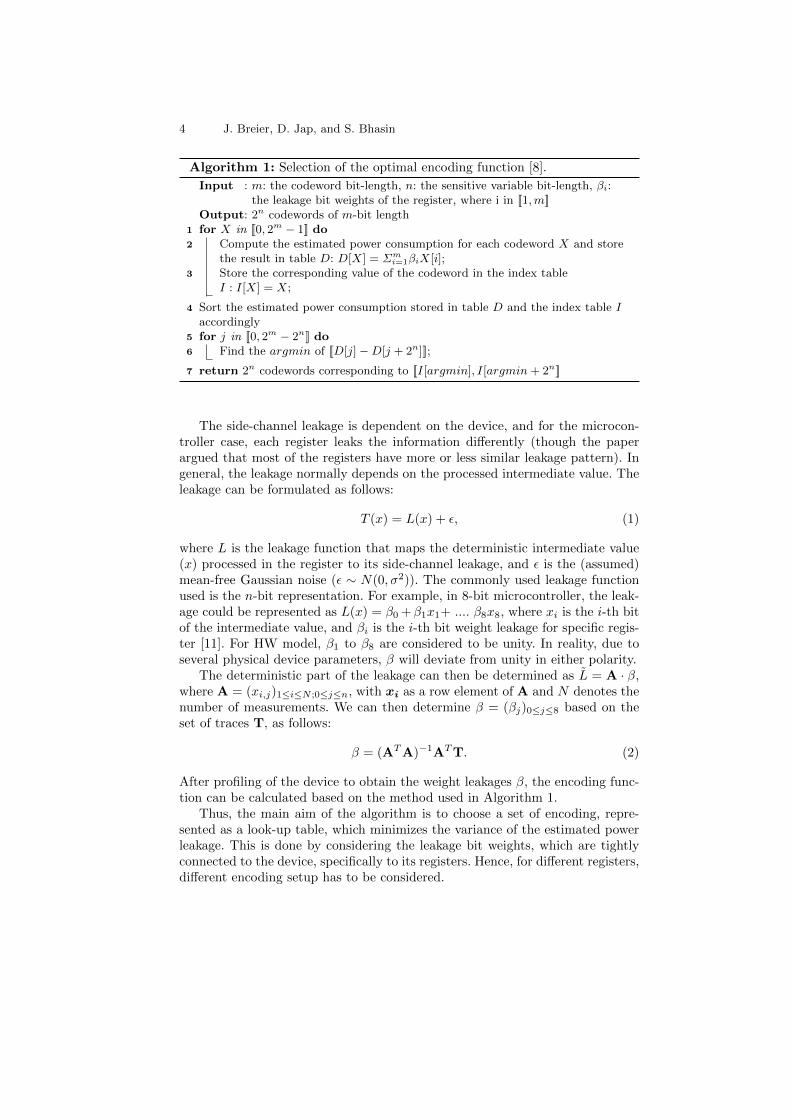
Algorithm 1: Selection of the optimal encoding function [8].
Input : m: the codeword bit-length, n: the sensitive variable bit-length, �i:the leakage bit weights of the register, where i in [[1,m]]
Output: 2n codewords of m-bit length1 for X in [[0, 2m � 1]] do2 Compute the estimated power consumption for each codeword X and store
the result in table D: D[X] = ⌃mi=1�iX[i];
3 Store the corresponding value of the codeword in the index tableI : I[X] = X;
4 Sort the estimated power consumption stored in table D and the index table Iaccordingly
5 for j in [[0, 2m � 2n]] do6 Find the argmin of [[D[j]�D[j + 2n]]];
7 return 2n codewords corresponding to [[I[argmin], I[argmin+ 2n]]
The side-channel leakage is dependent on the device, and for the microcon-troller case, each register leaks the information di↵erently (though the paperargued that most of the registers have more or less similar leakage pattern). Ingeneral, the leakage normally depends on the processed intermediate value. Theleakage can be formulated as follows:
T (x) = L(x) + ✏, (1)
where L is the leakage function that maps the deterministic intermediate value(x) processed in the register to its side-channel leakage, and ✏ is the (assumed)mean-free Gaussian noise (✏ ⇠ N(0,�2)). The commonly used leakage functionused is the n-bit representation. For example, in 8-bit microcontroller, the leak-age could be represented as L(x) = �0 +�1x1+ .... �8x8, where xi is the i-th bitof the intermediate value, and �i is the i-th bit weight leakage for specific regis-ter [11]. For HW model, �1 to �8 are considered to be unity. In reality, due toseveral physical device parameters, � will deviate from unity in either polarity.
The deterministic part of the leakage can then be determined as L = A · �,where A = (xi,j)1iN ;0jn, with xi as a row element of A and N denotes thenumber of measurements. We can then determine � = (�j)0j8 based on theset of traces T, as follows:
� = (ATA)�1
A
TT. (2)
After profiling of the device to obtain the weight leakages �, the encoding func-tion can be calculated based on the method used in Algorithm 1.
Thus, the main aim of the algorithm is to choose a set of encoding, repre-sented as a look-up table, which minimizes the variance of the estimated powerleakage. This is done by considering the leakage bit weights, which are tightlyconnected to the device, specifically to its registers. Hence, for di↵erent registers,di↵erent encoding setup has to be considered.

On Verifying Software Encoding Schemes against Fault Injection Attacks 5
Assembly code with look-up tables is stated in Appendix C. In this paper,we will refer to this implementation as to the ‘Device-Specific Encoding XOR’,as the dependence on leakage model, makes the encoding specific to a deviceregister.
2.4 Evaluating Resistance to Fault Injection Attacks
The first two countermeasures mentioned in this section were in-depth analyzedwith respect to fault injection attacks in [3]. To summarize the results, it wasshown that the Static-Encoding XOR implementation is more vulnerable to faultattacks due to fault propagation. Static-DPL XOR benefits from the table look-up properties that force the value to 0x00 every time a bad address is fetched tothe loading instruction. This implementation was further analyzed and improved,making the chance of a successful attack negligible.
In this paper, we analyze the Device-Specific Encoding XOR implementation,compare it with previous results and we provide insights that can help designersin developing encoding schemes that are resistant against fault attacks. To makethe paper self-contained, we reproduce the attacks of [3] and extend it to device-specific encoding.
3 Verification with the Code Analyzer
In order to formally verify the resistance of assembly code against fault injectionattacks, we have developed a code analyzer. This section contains the designand implementation details as well as the methodology we used for analyzingthe encoding implementations.
The architecture of our code analyzer is depicted in Fig. 1. Left side of thefigure shows the architecture of a standard microcontroller and right side is ahigh-level class diagram of our analysis software written in Java language. Thecode analyzer is a custom instruction set simulator that is capable of simulatingfaults at any stage of the code execution. Time complexity of the evaluation islinear.
Program code is fetched into the analyzer as a text file, following the assemblycode structure. It is then broken into instructions – di↵erent subclasses of theInstruction class. Memory contains all the look-up tables that are statically pre-programmed instead of fetching them from a file. Registers are implemented asarrays, containing 0x00 before the program execution. MuC class serves as theinstruction set simulator, executing instructions and performing operations onregisters and memory. This class also provides the fault injection functionality– it analyzes every instruction against a chosen fault model.
The modular approach to the code analyzer improves its reusability, whereit is only necessary to extend the instruction set in order to analyze a di↵erentdevice.

6 J. Breier, D. Jap, and S. Bhasin
Flash ProgramMemory
InstructionRegister
InstructionDecoder
ProgramCounter
DataSRAM
EEPROM
I/O Lines
GeneralPurposeRegisters
ALU
Statusand
Control
8-bit Data Bus
Memory
Map
Instruction
Class
Class
LDI
Class
MOV
Class
ADD ...
n
Registers
Array1
1
MuC
Class
1 1 1
.txt File
Microcontroller Code Analyzer
Fig. 1: Representation of microcontroller components in the Java code analyzer.
3.1 Fault Injection Analysis
The abstraction of the process of code execution and fault injection is depictedin Fig. 2. The middle part serves as a standard instruction set simulator, takingthe given input, executing the code and producing the output. This processis repeated for every possible combination of inputs for every instruction andevery fault model. We are analyzing resistance against four basic fault models:bit flip, random byte fault, instruction skip, and stuck-at fault. After the outputis produced, it is analyzed by the validator which decides whether the faultchanged the resulting value and if this value is useful for fault attack. We considerinputs and outputs already encoded, analyzing fault tolerance with respect toencoding/decoding is out of scope of this paper.
In the following, we will briefly describe parts of the code analyzer:
– Instruction Set Simulator: As stated previously in this section, the as-sembly code is fetched to the simulator as a text file. It accepts three di↵erentdata encoding formats, according to what algorithm is currently being used.For the Static-DPL XOR, it accepts input in the bit-sliced complement form:000000b0b0, therefore there are 4 possible input combinations. The Static-Encoding XOR accepts four bit complement format: b3b3b2b2b1b1b0b0, result-ing to 256 input combinations. The same number of combinations is analyzedfor the Device-Specific Encoding XOR, where the number of codewords is 16for 8-bit code.
– Fault Injection Simulator: In order to get the information about algo-rithm resistance against fault injection, we analyze four fault models. In the

On Verifying Software Encoding Schemes against Fault Injection Attacks 7
Instruction SetSimulator
Fault InjectionSimulator
Validator
a = 10101010b = 01010101
Input
r4 = 11010110
r4 = 11000110'
Fault Position
bit fliprandom byte faultinstruction skipstuck-at fault
Fault Model
x = 11110011Output
x = 11110011
Valid/Invalid
?
Output Checker
TargetCode
LDILDIEORST
abr5r4
r4r5r4c...
Fig. 2: Schematic of injecting a fault during the execution in the code analyzer.
case of a fault being injected into the data, we change the content of thedestination register of an instruction.
In bit flip fault model, we inject single and double bit flips into the Staticcountermeasures. There is no need to test other multiple bit flips, since all ofthem are just a subset of those two, because of DPL properties. Therefore,e.g. if an algorithm is not vulnerable against single bit flips, it will not bevulnerable against other odd-number bit flips, and vice-versa. In case of theDevice-Specific Encoding XOR, we test all possible combinations of bit flips.
Random byte fault model is a subset of bit flip fault model when it comesto code analysis, therefore this model is already included in the previoustesting.
To analyze vulnerable parts against instruction skip attack, we skip eitherone or two instructions from the code, checking all the possible combinations.More complex instruction skip models are not considered because of theimpracticability to implement them in the real environment.
Finally, to analyze the resistance against the stuck-at-fault model, we changethe value of the destination register either to 0x00 or to 0xFF.
– Validator: The final part of the code analyzer checks the resulting outputand assigns it to one of the following pre-defined groups:
• VALID: This is the most useful type of output an attacker can get. Out-puts in this category follow the proper encoding of analyzed algorithm,but the value deviates from the expected value with respect to giveninputs. A VALID fault can be directly exploited with fault injectionattack.
8 J. Breier, D. Jap, and S. Bhasin
• INVALID: This type of output does not follow the encoding. Therefore,it can be easily recognized by an output checker which can then decideto discard the value instead of further propagation.
• NULL: This type of fault has one of the following values: 0x00 or 0xFF.These outputs are mostly produced by look-up table implementationsand can be easily recognized as well.
4 Results
To analyze di↵erent software encoding countermeasures against fault injectionattacks, we implemented the basic operations of each previously discussed encod-ing scheme, i.e. Static-DPL XOR, Static-Encoding XOR, Static-Encoding LUTand Device-Specific Encoding XOR implementation. The corresponding code isprovided in the appendices. The analysis follows a two-step approach. The firststep involves a comprehensive fault analysis by putting the code under speciallydesigned code analyzer. The main objective of this comprehensive code analysisis to uncover any native vulnerabilities in the encoding scheme under individualfault models. Such analysis cannot be done in a practical setting due to limitedcontrol over the injected fault model for a given equipement setting. Albeit it ispossible to inject all the discussed fault models, it is not easy to control the faultmodel at will. In the following step, the corresponding code is implemented on areal AVR microcontroller and tested under laser fault injection. The objective ofpractical validation is to find which of the known vulnerabilities are produciblewith equipement at hand.
4.1 Code Analysis
To analyze vulnerabilities in the software encoding schemes, the basic operationswere fed to the code analyzer. The analyzer considers 3 di↵erent fault models,i.e. stuck-at, bit flips and instruction skip. Both single and multiple bit-flipsare possible. The first three analysed operations i.e. Static-DPL XOR, Static-Encoding XOR, Static-Encoding LUT are a special case, where more than 2-bit flips are equivalent to 1-bit or 2-bit flips eventually. The analyzer reportsthe impact on the final output in presence of discussed fault models. This isrepresented as a normalized distribution of faulty output for each consideredfault models. Three outputs are expected: VALID, INVALID and NULL. VALIDimplies that final faulty output stays within the encoding. Similarly, INVALIDrefers to the faulty output which is no longer in the applied encoding. NULLfaults are 0x00 or 0xFF values at the output. While VALID faults stay withinthe encoding and can lead to di↵erential fault analysis (DFA), it is rather lesslikely with INVALID faults. On the other hand, NULL deletes any data dependentinformation, disabling any further exploitation by DFA. Therefore, VALID faultsmust be prevented at all costs, while keeping INVALID in check and maximizingNULL faults. The analysis results for Static-DPL XOR, Static-Encoding XOR,
On Verifying Software Encoding Schemes against Fault Injection Attacks 9
(a) (b)
(c)
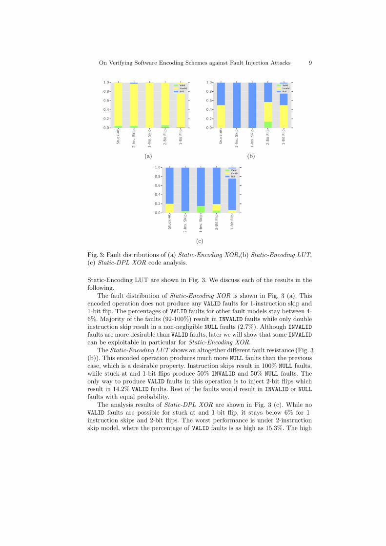
Fig. 3: Fault distributions of (a) Static-Encoding XOR,(b) Static-Encoding LUT,(c) Static-DPL XOR code analysis.
Static-Encoding LUT are shown in Fig. 3. We discuss each of the results in thefollowing.
The fault distribution of Static-Encoding XOR is shown in Fig. 3 (a). Thisencoded operation does not produce any VALID faults for 1-instruction skip and1-bit flip. The percentages of VALID faults for other fault models stay between 4-6%. Majority of the faults (92-100%) result in INVALID faults while only doubleinstruction skip result in a non-negligible NULL faults (2.7%). Although INVALID
faults are more desirable than VALID faults, later we will show that some INVALIDcan be exploitable in particular for Static-Encoding XOR.
The Static-Encoding LUT shows an altogether di↵erent fault resistance (Fig. 3(b)). This encoded operation produces much more NULL faults than the previouscase, which is a desirable property. Instruction skips result in 100% NULL faults,while stuck-at and 1-bit flips produce 50% INVALID and 50% NULL faults. Theonly way to produce VALID faults in this operation is to inject 2-bit flips whichresult in 14.2% VALID faults. Rest of the faults would result in INVALID or NULLfaults with equal probability.
The analysis results of Static-DPL XOR are shown in Fig. 3 (c). While noVALID faults are possible for stuck-at and 1-bit flip, it stays below 6% for 1-instruction skips and 2-bit flips. The worst performance is under 2-instructionskip model, where the percentage of VALID faults is as high as 15.3%. The high
10 J. Breier, D. Jap, and S. Bhasin
vulnerability against 2-bit flips can be explained by the fact, that 2-bit flips arethe limit of the dual-rail encoding scheme. Apart from these, the other faultsare more likely to be NULL rather than INVALID, which is desirable.
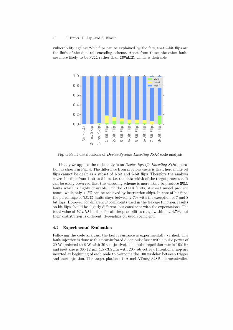
Fig. 4: Fault distributions of Device-Specific Encoding XOR code analysis.
Finally we applied the code analysis on Device-Specific Encoding XOR opera-tion as shown in Fig. 4. The di↵erence from previous cases is that, here multi-bitflips cannot be dealt as a subset of 1-bit and 2-bit flips. Therefore the analysiscovers bit flips from 1-bit to 8-bits, i.e. the data width of the target processor. Itcan be easily observed that this encoding scheme is more likely to produce NULLfaults which is highly desirable. For the VALID faults, stuck-at model producenones, while only < 2% can be achieved by instruction skips. In case of bit flips,the percentage of VALID faults stays between 2-7% with the exception of 7 and 8bit flips. However, for di↵erent � coe�cients used in the leakage function, resultson bit flips should be slightly di↵erent, but consistent with the expectations. Thetotal value of VALID bit flips for all the possibilities range within 4.2-4.7%, buttheir distribution is di↵erent, depending on used coe�cient.
4.2 Experimental Evaluation
Following the code analysis, the fault resistance is experimentally verified. Thefault injection is done with a near-infrared diode pulse laser with a pulse power of20 W (reduced to 8 W with 20⇥ objective). The pulse repetition rate is 10MHzand spot size is 30⇥12 µm (15⇥3.5 µm with 20⇥ objective). Intentional nop areinserted at beginning of each node to overcome the 100 ns delay between triggerand laser injection. The target platform is Atmel ATmega328P microcontroller,

On Verifying Software Encoding Schemes against Fault Injection Attacks 11
de-packaged and mounted on Arduino UNO development board. The surface areaof the chip is 3x3 mm2, which is manufactured in 350 nm CMOS technology.An X-Y positioning table with a step precision 0.05 µm is used to scan the chipsurface and perform laser injection. The timing of injection is synchronised withexecuted code using a code-generated trigger. The injection platform along withthe target is shown in Fig. 5.
Fig. 5: ATmega328P device under a near-infrared diode laser injection setup.
The prime di↵erence from the previous analysis is that in the experimen-tal validation, we do not precisely control the fault model. Moreover the faultmodels are not uniformly distributed. Before starting the real experiment, weperformed some profiling on the target with basic assembly code and verifiedthat all the fault models are possible to produce experimentally. Next, we flashthe assembly code of the four previously discussed software encoding operations.We essentially note the percentage of VALID, INVALID and NULL faults producedfor each tested operation. The results are summarised in Fig. 6.
Static-Encoding XOR shows the best consistency with the simulated anal-ysis previously (see Fig. 6 (a)). While 93.56% of the faults are INVALID, only5.88% VALID were produced. Moving towards Static-Encoding LUT, we observea 32.42% VALID faults in Fig. 6 (b). Since a VALID fault in this implementationcan only result from even bit flips, this infers that the fault model distribution isbiased towards multiple bit flips in our experiments. Similarly, we also observea 22.2% VALID faults in Static-DPL XOR (Fig. 6 (c)) owing to the prevalentmultiple bit flip model.

12 J. Breier, D. Jap, and S. Bhasin
When it comes to Device-Specific Encoding XOR (Fig. 6 (d)), results showdistribution very similar to the one obtained by the code analysis. Because it ismore likely to produce bit flips when injecting faults in the microcontroller, at13.5% an inflated number of VALID faults can be observed in this case, witha relatively small number of INVALID faults. As expected, NULL outputs aredominant i.e. 82.5% , because of the look-up table properties.
(a) (b)
(c) (d)
Fig. 6: Fault distributions of (a) Static-Encoding XOR,(b) Static-Encoding LUT,(c) Static-DPL XOR, and (d) Device-Specific Encoding XOR experiments.
5 Discussion
In this section, we will discuss some important parameters of particular encodingimplementation with respect to fault injection attacks.
5.1 Selection of � Coe�cients
We considered several parameters for the code analysis of Device-Specific En-coding XOR. We analyzed di↵erent � values scenarios. We considered the casewhere the variance of the � is relatively high (the �s might be cancelling eachother), and the case where the variance of the � is low (almost Hamming weight).

On Verifying Software Encoding Schemes against Fault Injection Attacks 13
The most significant di↵erence can be observed in the result for implemen-tation with � coe�cients that do not follow Hamming weight leakage model(stated in Fig. 7 (a)). From the figure, it can be observed that the number of1-bit flips is inflated, compared to the almost Hamming weight case (stated inFig. 7 (b)). The behavior of the faults shows contrast between di↵erent betavalues, which is not the case for other encoding schemes, and hence could befurther investigated.
(a) (b)
Fig. 7: Fault distributions of Device-Specific Encoding XOR code analysis with(a) high variance and (b) almost Hamming weight
5.2 Fault Propagation
When considering security of di↵erent implementations, fault propagation is animportant factor that can significantly a↵ect the possibility to mount an attack.In case we want to prevent a successful fault attack, it is necessary to avoidthe propagation of an INVALID output when it is fed as an input to a nextiteration of the algorithm. Otherwise, this output could leak some informationabout the processed data and therefore, allow an attacker to use the di↵erentialfault analysis.
From this point of view, look-up table implementations have an advantage,since every input that does not follow the encoding will be automatically con-verted to NULL. Analysis results of Static-DPL XOR, Static-Encoding LUT, andDevice-Specific Encoding XOR show that if any of the inputs is either INVALIDor NULL, it will always output NULL. Situation with the Static-Encoding XORis di↵erent because of the algorithm design. There are several combinations ofinputs that lead to VALID faults – more specifically, any combination of:
– Two INVALID inputs,– Two NULL inputs,– INVALID and NULL inputs.

14 J. Breier, D. Jap, and S. Bhasin
Moreover, for a combination of VALID and NULL inputs leaks a complete infor-mation about the VALID input in the form v3v3v2v2v1v1v0v0, where v3v2v1v0
is the original input.To summarize, table look-up implementations provide solid protection against
fault attacks when it comes to fault propagation. Any other implementation thatuses standard operations performed by using ALU, can be vulnerable if it is notdirectly designed with such goal in mind. Therefore, when designing a fault resis-tant algorithms along with the side-channel resistance, look-up tables can o↵erfault propagation cancellation by default.
6 Conclusion
This paper summarizes fault attack resistance of three software-based encodingschemes that were introduced to prevent side-channel attacks. We mainly aim atanalyzing the Device-Specific Encoding XOR implementation that was proposedrecently. Our results provide insights and comparison against the other schemes(‘Static’ encoding schemes) that have been analyzed in previous work [3].
In general, table look-up schemes o↵er higher level of security by thwart-ing the fault propagation in case of several algorithm iterations. Static-EncodingXOR might look the best from the experimental results, however, fault propa-gation properties of this design allow attacker to easily mount a DFA attack orto directly observe inputs passed to the algorithm in case of other input beingof a NULL type. After considering this phenomenon together with code analysisand experimental results, we conclude that the Device-Specific Encoding XORis currently the most secure scheme with respect to fault attacks and provides adecent level of security.
For the future work, we would like to extend the code analyzer to supportpipelined architectures, being able to discover vulnerabilities w.r.t. more com-prehensive fault models, like cache attacks (e.g. as described in [10]).
References
1. Biham, E., Shamir, A.: Di↵erential Fault Analysis of Secret Key Cryptosystems.In: CRYPTO ’97, LNCS, vol. 1294, pp. 513–525 (1997)
2. Breier, J.: On analyzing program behavior under fault injection attacks (to appear).In: Availability, Reliability and Security (ARES), 2016 Eleventh International Con-ference on. pp. 1–5. IEEE (Aug 2016)
3. Breier, J., Jap, D., Bhasin, S.: The other side of the coin: Analyzing software encod-ing schemes against fault injection attacks. In: 2016 IEEE International Symposiumon Hardware Oriented Security and Trust (HOST). pp. 209–216. IEEE (2016)
4. Chen, C., Eisenbarth, T., Shahverdi, A., Ye, X.: Balanced Encoding to MitigatePower Analysis: A Case Study. In: CARDIS. Lecture Notes in Computer Science,Springer (November 2014), paris, France
5. Dureuil, L., Potet, M.L., de Choudens, P., Dumas, C., Clediere, J.: From CodeReview to Fault Injection Attacks: Filling the Gap Using Fault Model Inference,pp. 107–124. Springer International Publishing, Cham (2016), http://dx.doi.
org/10.1007/978-3-319-31271-2_7

On Verifying Software Encoding Schemes against Fault Injection Attacks 15
6. Goubin, L., Patarin, J.: DES and Di↵erential Power Analysis. The ”Duplication”Method. In: CHES. pp. 158–172. LNCS, Springer (1999), Worcester, MA, USA
7. Hoogvorst, P., Danger, J.L., Duc, G.: Software Implementation of Dual-Rail Rep-resentation. In: COSADE (2011), Darmstadt, Germany
8. Maghrebi, H., Servant, V., Bringer, J.: There is wisdom in harnessing the strengthsof your enemy: Customized encoding to thwart side-channel attacks – extendedversion –. Cryptology ePrint Archive, Report 2016/183 (2016), http://eprint.iacr.org/
9. Rauzy, P., Guilley, S., Najm, Z.: Formally Proved Security of Assembly CodeAgainst Leakage. IACR Cryptology ePrint Archive 2013, 554 (2013)
10. Riviere, L., Najm, Z., Rauzy, P., Danger, J.L., Bringer, J., Sauvage, L.: High preci-sion fault injections on the instruction cache of ARMv7-M architectures. In: Hard-ware Oriented Security and Trust (HOST), 2015 IEEE International Symposiumon. pp. 62–67 (May 2015)
11. Schindler, W., Lemke, K., Paar, C.: A stochastic model for di↵erential side chan-nel cryptanalysis. In: International Workshop on Cryptographic Hardware andEmbedded Systems. pp. 30–46. Springer Berlin Heidelberg (2005)
12. Tiri, K., Verbauwhede, I.: A Logic Level Design Methodology for a Secure DPAResistant ASIC or FPGA Implementation. In: DATE’04. pp. 246–251 (2004), Paris,France.

16 J. Breier, D. Jap, and S. Bhasin
A Assembly Code For Static-DPL XOR Implementation
Table in this section contains assembly code used for the code analysis. Note thatthere are several di↵erences in comparison to the original paper. We prechargeall the registers before the code execution, therefore there is no need to useprecharge instructions. The other change is in instructions 7 and 8, where wefirst load the operation code (can take values 01010101 for and, 10101010 for or,and 01100110 for xor) and then we execute ldd instruction using the destinationregister, operation code and value. Look-up tables are stated in Table 2.
Table 1: Assembly code for DPL XOR in AVR# Instruction # Instruction
0 ldi r1 a 5 andi r2 00000011
1 ldi r2 b 6 or r1 r2
2 andi r1 00000011 7 ldi r4 operation
3 lsl r1 1 8 ldd r3 r4 r1
4 lsl r1 1 9 mov d r3
Table 2: Look-up tables for and, or, and xor
index 0000 - 0100 0101 0110 0111 - 1000 1001 1010 1011 - 1111
and 00 01 10 00 10 01 00
or 00 01 01 00 01 10 00
xor 00 10 01 00 01 10 00

On Verifying Software Encoding Schemes against Fault Injection Attacks 17
B Assembly Code for Static-Encoding XORImplementation
The code stated in Tab. 3 follows the originally proposed algorithm for Static-Encoding XOR. This implementation uses several constants, either for clearingand precharging the registers before loading the data (e.g. ldi r16 11110000),or for changing the data to proper encoding format (e.g. ldi r17 01011010).
Table 3: Assembly code for Encoding XOR in AVR# Instruction # Instruction
0 ldi r1 a 19 and r20 r1
1 ldi r2 b 20 and r21 r1
2 ldi r16 11110000 21 swap r21
3 ldi r17 11110000 22 or r20 r21
4 and r16 r1 23 ldi r22 00001111
5 and r17 r1 24 ldi r23 00001111
6 swap r17 25 and r22 r2
7 or r16 r17 26 and r23 r2
8 ldi r18 11110000 27 swap r23
9 ldi r19 11110000 28 or r22 r23
10 and r18 r2 29 ldi r21 10100101
11 and r19 r2 30 eor r20 r21
12 swap r19 31 eor r20 r22
13 or r18 r19 32 ldi r24 11110000
14 ldi r17 01011010 33 ldi r25 11110000
15 eor r16 r17 34 and r24 r16
16 eor r16 r18 35 and r25 r20
17 ldi r20 00001111 36 or r24 r25
18 ldi r21 00001111
18 J. Breier, D. Jap, and S. Bhasin
C Assembly Code for Device-Specific Encoding XORImplementation
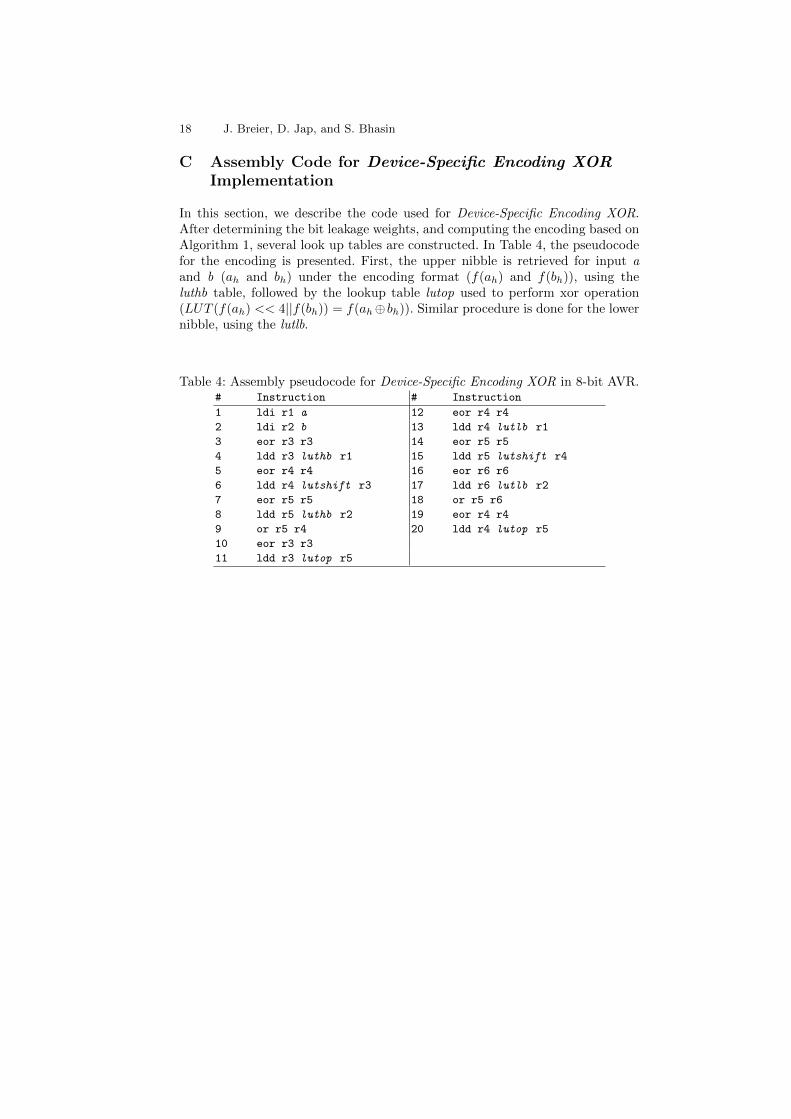
In this section, we describe the code used for Device-Specific Encoding XOR.After determining the bit leakage weights, and computing the encoding based onAlgorithm 1, several look up tables are constructed. In Table 4, the pseudocodefor the encoding is presented. First, the upper nibble is retrieved for input aand b (ah and bh) under the encoding format (f(ah) and f(bh)), using theluthb table, followed by the lookup table lutop used to perform xor operation(LUT (f(ah) << 4||f(bh)) = f(ah� bh)). Similar procedure is done for the lowernibble, using the lutlb.
Table 4: Assembly pseudocode for Device-Specific Encoding XOR in 8-bit AVR.# Instruction # Instruction
1 ldi r1 a 12 eor r4 r4
2 ldi r2 b 13 ldd r4 lutlb r1
3 eor r3 r3 14 eor r5 r5
4 ldd r3 luthb r1 15 ldd r5 lutshift r4
5 eor r4 r4 16 eor r6 r6
6 ldd r4 lutshift r3 17 ldd r6 lutlb r2
7 eor r5 r5 18 or r5 r6
8 ldd r5 luthb r2 19 eor r4 r4
9 or r5 r4 20 ldd r4 lutop r5
10 eor r3 r3
11 ldd r3 lutop r5