mitigation of intergranular stress …...mitigation of intergranular stress corrosion cracking in...
TRANSCRIPT

INTERNATIONAL ATOMIC ENERGY AGENCY
IAEA-EBP-IGSCC
MITIGATIONOF INTERGRANULAR
STRESS CORROSION CRACKINGIN RBMK REACTORS
FINAL REPORT OF THE PROGRAMME’S STEERING COMMITTEE
A PUBLICATION OF THEEXTRABUDGETARY PROGRAMME ON MITIGATION OF
INTERGRANULAR STRESS CORROSION CRACKINGIN RBMK REACTORS
September 2002

This publication has been prepared by the:
Special Projects Unit Division of Nuclear Installation Safety International Atomic Energy Agency
Wagramer Strasse 5 P.O. Box 100
A-1400 Vienna, Austria
MITIGATION OF INTERGRANULAR STRESS CORROSION CRACKING IN RBMK REACTORS: FINAL REPORT OF THE PROGRAMME’S STEERING COMMITTEE
IAEA, VIENNA, 2002 IAEA-EBP-IGSCC
© IAEA, 2002
Printed by the IAEA in Austria September 2002

FOREWORD
In 2000 the IAEA initiated an Extrabudgetary Programme on Mitigation of Intergranular Stress Corrosion Cracking in RBMK Reactors to assist countries operating RBMK reactors in addressing the issue in austenitic stainless steel 300 mm diameter piping.
Intergranular stress corrosion cracking of austenitic stainless steel piping in BWRs has been a major safety concern since the early seventies. Similar degradation was found in RBMK reactor piping in 1997. Early in 1998 the IAEA responded to requests for assistance from RBMK operating countries on this issue through activities organized in the framework of Technical Co-operation Department regional projects and the Extrabudgetary Programme on the Safety of WWER and RBMK Nuclear Power Plants. Results of these activities were a basis for the formulation of the objective and scope of the Extrabudgetary Programme on Mitigation of Intergranular Stress Corrosion Cracking in RBMK reactors (“the Programme”).
The scope of the Programme included in-service inspection, assessment, repair and mitigation, and water chemistry and decontamination. The Programme was pursued by means of exchange of experience, formulation of guidance, transfer of technology, and training, which will assist the RBMK operators to address related safety concerns.
The Programme implementation relied on voluntary extrabudgetary financial contributions from Japan, Spain, the United Kingdom and the USA, and on in kind contributions from Finland, Germany and Sweden. The Programme was implemented in close co-ordination with ongoing national and bilateral activities and major inputs to the Programme were provided through the activities of the Swedish International Project Nuclear Safety and of the US DOE International Nuclear Safety Program. The RBMK nuclear power plants in Lithuania, Russian Federation and Ukraine hosted most of the Programme activities. Support of these Member States involved in the Programme was instrumental for its successful completion in 2002.
This report summarizes the main results, conclusions and recommendations of the Programme.
More detailed information is included in 35 technical reports prepared in the framework of this Programme which are available on http://www.iaea.org/ns/nusafe/ebpigscc.htm along with other information on the Programme.
The contributions of all those involved in the Programme is greatly appreciated. In particular, the contribution in the preparation of this report provided by A. Arzhaev, B. Brickstad, J. Lance, M. Mayfield, L. Poulter, A. Roberts, U. Staudt and T. Taylor is acknowledged. The IAEA officer responsible for this report was R. Havel of the Division of Nuclear Installation Safety.

EDITORIAL NOTE
The use of particular designations of countries or territories does not imply any judgement by the publisher, the IAEA, as to the legal status of such countries or territories, of their authorities and institutions or of the delimitation of their boundaries.
The mention of names of specific companies or products (whether or not indicated as registered) does not imply any intention to infringe proprietary rights, nor should it be construed as an endorsement or recommendation on the part of the IAEA.

CONTENTS
1. INTRODUCTION.................................................................................................................. 1
2. BACKGROUND.................................................................................................................... 2
2.1. System description ......................................................................................................... 2 2.2. Cracking history ............................................................................................................. 3 2.3. Inspection issues............................................................................................................. 4 2.4. Flaw assessment issues................................................................................................... 5
3. HISTORY OF THE PROGRAMME..................................................................................... 5
3.1. Programme initiation...................................................................................................... 53.2. Programme implementation ........................................................................................... 6
4. CAUSES OF CRACKING................................................................................................... 10
4.1. Root causes................................................................................................................... 104.2. Contributory factors ..................................................................................................... 114.3. Metallurgical investigations ......................................................................................... 164.4. Cracking history evaluations........................................................................................ 194.5. Water chemistry ........................................................................................................... 21
5. GENERAL CONCLUSIONS AND RECOMMENDATIONS........................................... 22
5.1. Improved in-service inspection .................................................................................... 225.1.1. Manual ultrasonic inspection techniques ......................................................... 23 5.1.2. Development of qualification criteria for ultrasonic inspection....................... 24 5.1.3. Recommendations ............................................................................................ 24
5.2. Flaw assessment and impact on inspection requirements ............................................ 255.2.1. Flaw assessment methods................................................................................. 25 5.2.2. Crack growth rates ........................................................................................... 25 5.2.3. Recommended inspection requirements........................................................... 26 5.2.4. Radiation dose issues ....................................................................................... 27 5.2.5. Leak before break considerations..................................................................... 27
5.3. Pipe repair and mitigation methods.............................................................................. 28 5.3.1. Optimization of repair welding technology ..................................................... 28 5.3.2. Weld overlay repair .......................................................................................... 29 5.3.3. Qualification of mitigation techniques............................................................. 29
5.4. Other IGSCC mitigation strategies .............................................................................. 295.4.1. Adequate monitoring of anions / action levels in reactor water....................... 29 5.4.2. Water chemistry monitoring systems............................................................... 29 5.4.3. General quality of feed water ........................................................................... 30 5.4.4. Deaeration ........................................................................................................ 30 5.4.5. ECP measurements........................................................................................... 30 5.4.6. Decontamination processes .............................................................................. 31 5.4.7. Replacement of copper alloys .......................................................................... 31 5.4.8. Implementation of alternative water chemistries ............................................. 31
APPENDIX I. SUMMARY REPORTS OF THE WORKING GROUPS............................... 33

APPENDIX III. LIST OF PROGRAMME ACTIVITIES....................................................... 51
REFERENCES......................................................................................................................... 53
ABBREVIATIONS.................................................................................................................. 56
CONTRIBUTORS TO DRAFTING AND REVIEW ............................................................. 57
APPENDIX II. LIST OF PROGRAMME PARTICIPANTS.................................................. 48

1
1. INTRODUCTION
Since 1997 RBMK reactors have experienced cracking in portions of their stabilized stainless steel piping systems, which has the characteristics of intergranular stress corrosion cracking (IGSCC), similar to what had been experienced by western boiling water reactors (BWRs). While no through wall cracks have been detected to date, such cracking incidents pose a threat to the integrity of the primary pressure boundary that if not managed and mitigated, can increase the likelihood of a loss of coolant accident. Although rupture of these 300 mm diameter pipes is within the parameters of a design basis accident, there is still the potential for damage to the reactor core and the release of radioactivity to the atmosphere.
In 1998, Member States operating RBMK reactors requested assistance in managing and mitigating IGSCC. The IAEA responded to these requests by organizing a workshop in Slavutych, Ukraine [1]. In the period 1998–1999 the IAEA convened two follow-up meetings to discuss the issue and exchange related experience [2, 3]. A dedicated international programme to assist regulators and plant operators in Lithuania, Russian Federation and Ukraine was launched early in 2000. This programme was named the “Programme on Mitigation of Intergranular Stress Corrosion Cracking in RBMK Reactors”1. The Programme was undertaken as a complement to existing national, bilateral and international activities, taking full advantage of their results and ongoing efforts, and paying specific attention to co-ordination in order to avoid duplication and obtain achievable leverage effects. The Programme concluded in mid-2002. The initial activities were funded through the IAEA’s regional technical co-operation projects. The Programme was funded primarily by voluntary contributions from several IAEA Member States as an Extrabudgetary Programme (EBP), with continued support of the Department of Technical Co-operation.
The objective of the Programme on Mitigation of Intergranular Stress Corrosion Cracking in RBMK Reactors was to assist RBMK operating countries in mitigating IGSCC in austenitic stainless steel piping, emphasizing four technical areas:
Improvements in in-service inspection performance and qualification Comprehensive assessment techniques Qualification of repair techniques Water chemistry and decontamination methods.
Throughout the Programme, the activities were carried out with the main focus on ensuring reactor coolant system integrity and without consideration of generation specific design safety features. The Programme did not deal with plant life extension issues.
Programme implementation was based on the IAEA practices and its developed infrastructure for providing nuclear safety assistance. The activities were carried out by four Working Groups (WGs) that addressed the above technical areas, under guidance and co-ordination of a Programme Steering Committee (SC). The main part of the work was performed by the individuals and organizations involved in the Working Groups. The Programme meetings served mainly for co-ordination. Strong elements of the Programme were training and technology transfer, which were mainly supported by the ongoing bilateral and international activities of the respective Member States.
1 The “Programme on Mitigation of Intergranular Stress Corrosion Cracking in RBMK Reactors” will be hereafter identified as “The Programme,” or simply “Programme”.

2
This final report is based on comprehensive reports prepared by each of the Working Groups (summaries of which are contained in Appendix I). It presents a description of the problem, an overview of the history of the Programme, findings on the root cause for RBMK pipe cracking, overall conclusions and recommendations to mitigate the problem, and status of their implementation.
It should be noted that the results, recommendations and conclusions resulting from this IAEA Programme are intended only to assist national decision makers who have the sole responsibilities for the regulation and safe operation of their nuclear power plants and do not replace respective activities, which need to be performed within the national licensing processes.
2. BACKGROUND
2.1. SYSTEM DESCRIPTION
RBMK reactors are pressure tube reactors that have been built in Russian Federation, Ukraine and Lithuania. There are three generations of RBMK reactors, with the first reactor having commenced operation in 1973 (Leningrad 1) and the most advanced version having commenced operation in 1990 (Smolensk 3). The RBMKs are amongst the most physically massive reactors in operation, as well as the most powerful. Ignalina reactors are rated at 4800 MW thermal, 1500 MW electrical. All other RBMK reactors are rated at 1000 MW electrical. Detailed technical descriptions of these reactors are included in [4, 5, 6].
A layout of one circulation loop, Fig. 1, shows the extensive piping and hence numerous weld joints in RBMK cooling circuits. Each reactor contains two such loops. The components where the risk from IGSCC is considered the greatest are nominally 300 mm diameter piping. These include the 48 downcomers from the steam separators (SS) to the suction header (SH), the 40–44 group distribution headers (GDH), the 2 water equalizing pipes (WEP) between each pair of the steam separators, and the 40–44 sections of pressurized pipe that connect between the pressure header and the group distribution header (note this is absent in first generation RBMKs). There are also some sections of the emergency core cooling systems (ECCS) pipe and the blowdown and cooling system pipe that are considered at risk. At Ignalina reactors, there are also 6 bypass lines between the suction and pressure headers.
Although the basic designs of all the RBMK reactors are very similar, there are differences in the safety systems. The first generation reactors were originally provided with an ECCS only capable to compensate for 300 mm dia. pipe rupture in the suction part of the main circulation circuit (MCC). Recently upgrades to the ECCS to cope with 300 mm dia. ruptures in both suction and discharge parts of the MCC have been designed and are being implemented in line with respective utility plans and licensing requirements.
Later reactors, such as Smolensk 1 and 2 and Kursk 3 and 4 have more powerful ECCS systems as well as partial suppression type containments, called the accident localization systems (ALS). Accident analyses predict that these plants should withstand the break of two downcomers without core damage.
Failure of a group distribution header (GDH) is more significant than failure of 300 mm diameter piping even though the piping diameters are similar. This is because such a break

3
would prevent water reaching a group of fuel channels. Even so, reverse flow may allow a shutdown without core damage.
FIG. 1. RBMK Main circulation loop.
2.2. CRACKING HISTORY
In January 1997, during routine in-service radiographic inspections, cracks were found in 35% of the 974 welds of 300 mm diameter austenitic piping in Leningrad Unit 3. None of these cracks were through wall cracks. The areas were removed for investigation and

4
intergranular cracks were found in the heat affected zone (HAZ). These had the classical characteristics of IGSCC studied extensively in western BWRs.
Inspection of sample welds of similar piping carried out later at Kursk Unit 1 revealed defects in 5 welds out of 80 inspected, after which 100 percent inspection was performed.
By early 1998, it was clear that IGSCC posed a generic problem that was affecting all 14 operating RBMKs to some degree. However there are several aspects of the cracking which are yet unexplained and leave the “root cause” as an open question. For example, it is the later RBMKs such as Leningrad Unit 3 and Chernobyl Unit 3 that appear most affected, with some of the first generation RBMKs being among the least affected. Obviously, the explanation for cracking appears to be more complex than one purely focused on the age of the reactor.
In a similar manner, it has not been possible to make an easy correlation between factors which often affect the propensity for defects, such as whether the welds were made off-site (factory welds) or on-site at the reactor (site welds). Thus at Chernobyl Unit 3, a greater proportion of on-site welds exhibit IGSCC; whereas at Leningrad Unit 3 and at the two Ignalina reactors, it is the factory welds that appear worse.
Defects of crack lengths over 250 mm have been reported (26% pipe circumference), with depths in some cases up to 12 mm (75% of pipe wall thickness). However, the great majority of such defects are smaller.
One reason that the occurrence of IGSCC in RBMKs is so significant is that, being pressure tube reactors, there is necessarily a large amount of piping, much more than in a pressure vessel type reactor. Therefore any problem with the pipe inevitably generates a large maintenance task, with associated economic and radiation dose issues. There are over 1500 welds in austenitic pipe in the intermediate diameter range of 300 mm and wall thickness of 15–16 mm per RBMK reactor. Most attention has been focused on these welds, although there are other components made of the same austenitic steel for which IGSCC may be of significance. Accordingly, any inspection, repair or mitigation technique that has to be applied individually to such a large number of welds will be expensive and lead to significant radiation doses being received by the staff.
2.3. INSPECTION ISSUES
Inspection of austenitic steel welds for IGSCC is inherently difficult. Radiographic inspection is not reliable, in particular at early stages of crack development. When using ultrasonic inspection, the material properties of austenitic steel can distort the sound wave which decreases the signal to noise ratio. Inspection of piping welds may also be hindered by physical access that can limit inspection to a single side of the weld.
Despite the problems associated with inspection of austenitic pipe welds, international studies have shown that the inspection reliability of austenitic pipe welds with access to both sides is reasonably good. However, when access limitations require the detection of defects by transmitting ultrasound through the weld metal (single side access), inspection reliability can be poor.
Both manual and automated techniques have been developed for pipe inspections. Automated techniques are more easily repeatable and lend themselves to data recording which

5
allows the best incremental measurements to be made over time. However, manual techniques have the advantage that the operator can more easily adjust a transducer position and orientation to highlight particular signals.
Human factor effects are now generally accepted as playing a considerable role in the quality of inspections performed. Human factors are of particular concern when inspection is carried out under difficult environmental conditions or when the radiation dose rates are high. This is certainly applicable to in-service inspection (ISI) in RBMK reactors. Data interpretation errors, failures to inspect certain areas, and incorrect recording of data, also have been noticed in studies and actual plant inspections worldwide.
2.4. FLAW ASSESSMENT ISSUES
Flaw assessment techniques are important to the prediction of flaw growth and the determination of inspection intervals and repair criteria. The fundamental techniques are accepted worldwide but there are several issues related to their implementation for IGSCC in RBMK piping systems. There are no major differences in the resulting allowable flaw sizes between the Russian and western approaches. However, there are three key issues that require resolution with respect to IGSCC damage in RBMKs:
1. Defects are only detectable above a certain size. There is a disagreement (of a less important nature) between the Russian specialists and others, as to how this phenomenon is described. However, there is no disagreement with the general principle that any particular flaw may not be detectable until it has reached a certain size, depending on capabilities of ISI procedures applied and the ISI schedule. The effectiveness of ISI procedures is a key parameter, which should be demonstrated by a qualification process.
2. Defects initiate and grow under the influence of stress. There are no good theories describing initiation time for IGSCC. Growth rate is variously described as being effectively constant over a range of stress intensity factors, which is the Russian position; or variable according to a power law, which is the western position. In either cases, the data for stabilized stainless steels, on which the crack growth rate relationship is made, is sparce. This influences determination of the inspection intervals.
3. Unrevealed defects may reach a critical size where failure occurs. The ISI schedule in addition to ISI effectiveness, should be oriented to guarantee the low probability of double ended guillotine break. Defects of limited initial length will probably exhibit leak before break (LBB) behaviour. The focus should also be on reliable detection of crack growth in length (circumferential).
3. HISTORY OF THE PROGRAMME
3.1. PROGRAMME INITIATION
Recognizing the importance of the issue, and upon invitation of the Government of Ukraine, the IAEA organized in the frame of the TC Project RER/9/052 a Workshop on ‘Environmentally Assisted Cracking of NPP Austenitic Piping’ in Slavutych, Ukraine, 22–26 June 1998 [1]. The objective of the workshop was to provide a forum for the exchange of experience. The workshop concluded that actions to address the issue of IGSCC in RBMK

6
reactors have been initiated but still need to be completed. Further exchange of experiences and international co-operation in this area was of high importance. Follow-up activities to address safety concerns associated with this issue for RBMK reactors were recommended as a matter of urgency.
In order to develop comprehensive well-balanced proposals for follow-up activities necessary to address the issue of IGSCC, which were consistent with the conclusions of the workshop [1], the IAEA convened two meetings in Vienna, 27–30 October 1998 [2] and 12–15 April 1999 [3]. A Programme Proposal “Mitigation of IGSCC in RBMK Reactors” was developed [3], addressing the issue in four technical areas:
Improvements in in-service inspection performance and qualification Comprehensive assessment techniques Qualification of repair techniques Water chemistry and decontamination techniques.
It was also proposed to establish a Steering Committee to guide and co-ordinate the Programme implementation and to take over some responsibilities originally intended to be carried out in a separate technical area dealing with safety assessment.
The Programme proposal was then submitted for consideration by IAEA Member States that had indicated interest in supporting such assistance.
3.2. PROGRAMME IMPLEMENTATION
Late in 1999, the Governments of Japan and of the USA agreed to fund the Programme as an Extrabudgetary Programme (joined later by the Governments of Spain and the UK). At the beginning of 2000, the IAEA invited countries operating RBMK reactors and countries operating BWRs and having relevant experience of managing IGSCC to participate in the Programme.
The Programme Steering Committee was formed with membership from:
Regulatory bodies from Lithuania, Russian Federation and Ukraine All RBMK plants RBMK designer NIKIET Countries providing in-cash or major in-kind support to the Programme Working Group leaders IAEA Secretariat.
The Steering Committee met for the first time in Vienna, 16–19 May 2000, which also marks the formal initiation of the EBP. The SC Terms of Reference (Table I), Programme structure and implementation (based on 4 Working Groups), preliminary work plans and composition of WGs, final EBP output and subsequent actions were discussed and agreed upon [7].

7
TABLE I. STEERING COMMITTEE TERMS OF REFERENCE
The Steering Committee of the Programme provides guidance on its implementation and:
Advises the IAEA on Programme implementation and recommends related actions
Monitors the Programme progress, collects, co-ordinates, and assimilates the results of projects (Working Groups) addressing specific aspects of the problem, and promotes practical implementation of programme results at the national level
Provides a forum for the exchange of information on related work underway and planned and advises the IAEA on matters requiring co-ordination with the national, bilateral and international activities
Collects and evaluates information about safety assessments implemented for RBMK plants applicable to IGSCC and reviews all reports prepared in the frame of the programme
Assures that the efforts of the Working Groups and of the programme as a whole remain focused on safe operation of RBMK plants
Assures that the efforts of the Working Groups span the full spectrum of technical issues that provide a reasonable basis for addressing the fundamental safety issue raised by IGSCC
Assures that recommendations take full account of radiological dose considerations
Provides a final report describing methods for managing IGSCC in RBMK reactors.
The four Working Groups each developed their own set of objectives which were approved by the Steering Committee.
Working Group 1
The overall objective of the Improvements in in-service inspection performance and qualification Working Group was to cooperate with Lithuanian, Russian and Ukrainian ISI specialists to improve the reliability of ultrasonic inspection techniques for detection and characterization of IGSCC in austenitic piping. The three objectives were to:
1. Transfer improved ultrasonic inspection techniques for flaw detection and characterization.
2. Develop performance demonstration criteria for ultrasonic inspection. 3. Transfer risk informed in-service inspection technology.
Working Group 2
The four objectives of the Comprehensive assessment techniques WG were to:
1. Recommend a break preclusion procedure that, using ISI results, can form the basis for decisions for safe operation until the next inspection.
2. Recommend target sizes for flaws that need to be detected during ISI depending on the inspection interval.
3. Improve the understanding of the root cause cracking mechanism of IGSCC in RBMK plants.
4. Exchange and transfer knowledge on risk based inspection procedures that can be relevant for RBMK plants.

8
Working Group 3
The overall objective of the Qualification of repair techniques WG was to transfer methods and techniques for repairing pipes with existing cracks and mitigating cracking in un-cracked welds. The three objectives were to:
1. Recommend optimized welding technologies that will reduce susceptibility of welds to IGSCC. One of the issues is the technology of automatic gas–tungsten automated welding (GTAW) being used as the repair means at RBMK reactors.
2. Recommend and transfer optimized overlay welding technology for repair and stress mitigation of weldments with flaw indications.
3. Solve issues related to mitigation technologies for stabilized austenitic steel weldments. There are two main technologies of interest:
mechanical stress improvement process (MSIP) local solution heat treatment.
Working Group 4
The overall objective of the Water chemistry and decontamination techniques WG was to investigate the role of chemistry in the cracking of RBMK piping and to recommend remedial actions. The three objectives were to:
1. Compile data on decontamination experience with RBMK reactors and western reactors, with particular emphasis on the possible effect of decontamination agents on IGSCC susceptibility of structural materials.
2. Collect data on key water chemistry parameters in RBMKs, such as conductivity, pH, anion and cation contents and oxygen, and analyze trends within plants as well as across plants, with a view to identifying key parameters controlling IGSCC.
3. Compare water chemistry monitoring systems and practices for RBMKs and BWRs to see if any western practices should be adopted by RBMKs.
The first round of WG meetings took place in the period July–October 2000 and each WG developed a detailed work plan and assigned actions to its members [8–12].
It was also agreed that the WG meetings and training activities should take place primarily in RBMK operating countries.
The 2nd SC meeting [13], held in Vienna, 5–7 December 2000, reviewed the WGs work plan proposals with respect to gaps, overlaps and interfaces and approved them with minor revisions. The SC also approved the final Programme membership. In total 82 experts from Canada, Finland, Germany, Japan, Lithuania, Russian Federation, Spain, Sweden, Ukraine, UK and the USA participated in the Programme activities (total 28 meetings and training courses/workshops). Emphasis was given to involvement of RBMKs operators and in each WG, all RBMKs were represented with only one exception. The list of Programme participants is provided in Appendix II and the list of Programme activities in Appendix III.
The progress achieved in the four WGs [14–17, 19] and the Programme overall status [18] was reviewed during the 3rd SC meeting held in Vienna, 29–31 May 2001, which also provided guidance for the Programme implementation for the remaining 12 months in order

9
to achieve the overall EBP objective [20]. The RBMK operators described their view of success for the EBP Programme which is provided in Table II.
TABLE II. RBMK OPERATORS VIEW OF EBP SUCCESS CRITERIA
Working Group 1
A qualified procedure for manual inspection of welds to determine defect size where access is limited
A process for qualifying inspection procedures that meets ENIQ methodology requirements
A procedure for inspecting weld overlays that has been adapted to Russian requirements, although the procedure will not go through the qualification process under the EBP.
An inspection procedure for inspecting welds before and after application of the MSIP process.
Working Group 2
Recommendations on target defect size for ISI to ensure safe operation between inspections
Main factors leading to IGSCC in 300 mm diameter piping
Recommendations on establishing break preclusion methodology
Working Group 3
Manual and automatic welding procedures for 300 mm diameter pipe
Weld overlay repair techniques
Weld root protection techniques
Heat sink welding
MSIP recommendations
Working Group 4
Practical recommendations for water chemistry improvement
Recommendations for implementing ECP measurements to monitor IGSCC in RBMK’s
Effects of decontamination on IGSCC and recommendations for improved decontamination process
The Steering Committee found the RBMK operators definition of success consistent with the deliverables of the WG, as described in Section 5 of this report.
The 4th and final SC Meeting, held in Vienna 21–23 May 2002, took note of the progress achieved and reviewed, provided comments and modifications and approved each of the Working Group final reports. The SC then reviewed in detail the final draft SC Report on the Programme and agreed upon required changes [21–29].
A strong element of the Programme was technology transfer. Therefore, in parallel with the SC and WGs meetings, which served mainly co-ordination purposes, a number of workshops, seminars, training courses and pilot studies took place:
Workshop on Risk based inspection [30] Advanced ultrasonic training seminar for detection, characterization and repair of IGSCC, IGSCC flaw sizing and weld overlay examination (including transfer of respective procedures) [31, 32]

10
Advanced ultrasonic training course for detection and characterization of IGSCC in stainless steel piping [33, 34] Automated IGSCC ultrasonic inspection seminar [35] Advanced ultrasonic sizing seminar [36, 37] Workshop on GTAW welding and repair methods [38] Workshop on Water chemistry monitoring (Gundremmingen and Philippsburg NPPs) [39] Workshop on IRBIS (Ignalina risk based inspection pilot study) results [40] UT Qualification Pilot Study [41] Training seminar on UT inspection of piping repaired by weld overlay [42, 43]Pilot Study on in-plant measurement of electrochemical potential (ECP) in Ignalina NPP.
The training was organized in close co-operation with the ongoing bilateral assistance, such as the Swedish International Project Nuclear Safety (SIP) and US DOE International Nuclear Safety Program (INSP) and was an additional in kind contribution of the participating Member States to the Programme.
4. CAUSES OF CRACKING
The purpose of this section is to present the evidence collected that leads to conclusion of the “root cause” of pipe cracking in RBMK reactors. Knowledge of root cause is central because it can help to:
design in-service inspection plans with respect to both inspection locations and frequencies perform analyses aimed at exclusion of double ended guillotine break potential analyze the issues of crack initiation and growth (including re-initiation after repair) develop effective pipe repair procedures develop methods to eliminate the cracking phenomenon.
4.1. ROOT CAUSES
Cracking of 300 mm diameter titanium stabilized stainless steel pipe (08Ch18N10T) in RBMK reactors is the result of intergranular stress corrosion cracking (IGSCC), just as has been observed in non-stabilized and stabilized stainless steel piping in western BWRs. Overall, the highest number of cracking indications has occurred in the downcomer sections and group distribution headers, Fig. 1.
IGSCC arises with the simultaneous occurrence of three critical parameters: material condition, stress condition and water chemistry. Of all the factors that are involved in the interaction of these three conditions, the following three appear to be the critical ones for RBMK piping:
Some level of thermal sensitization due to welding (chromium depleted grain boundaries). There is no true threshold sensitization level, but cracking is easier the more the pipe is sensitized, and vice versa (for example, slow strain rate tests on A321

11
type steel revealed no IGSCC when measured DL EPR ratios were below 1%). The sensitization may be further enhanced by the phenomenon of low temperature sensitization that occurs during long term operation. High tensile residual stresses, plastic strain and deformation derived from the pipe weld preparation and welding process. An oxidizing reactor water environment, with total concentrations of chloride and sulfate above 10 µg/kg, which strongly affects water conductivity.
All other variables (such as operating stresses, other water impurities and metallurgy) are considered to be secondary in nature and may account for the observed variability in cracking locations from plant-to-plant and different crack sizes for similar operating times.
Stress corrosion cracking is a two step process: (1.) crack initiation and (2.) sub critical crack propagation. IGSCC modelling [44] for the case of sensitized AISI 304 type stainless steel clearly shows that crack propagation takes place with a variable crack growth rate, which is strongly correlated to parameters such as water chemistry, weld residual stresses and material characteristics. The metallurgical investigation of cracks removed from the RBMK piping suggests that preexisting surface features have led to early crack initiation and therefore it is believed that the life limiting factor for affected welds is crack propagation. However, early crack initiation does not necessarily predict a fast crack growth rate.
There were no through wall cracks observed in 300 mm piping in RBMKs. For the RBMK case, Russian specialists explain this to be due to reduction of sensitization along the fusion line from inner to outer surface, reduction of plastic strains introduced by multi-pass welding, and change of residual stresses from tensile in the weld root to compressive stresses close to the outer surface of the pipe. However, Western experts point out that there is no sensitization threshold, and so, if there is tensile stress, a crack has a finite probability of growing, albeit slowly, even in non-sensitized material. Cracking will stop in either a compressive stress field (which results in a negative stress intensity factor) or if the crack tip is deformed and hence blunted. But it is not clear how such conditions would routinely be sustained in the pipe wall. Therefore, it cannot be concluded that cracks would not ever reinitiate and grow through the pipe wall.
The following sections summarize the supporting information. Details are contained in the WG reports, particularly those of Working Group 2 and Working Group 4, Appendix I of this report and [27, 29].
4.2. CONTRIBUTORY FACTORS
A very large body of research has substantiated beyond doubt that intergranular stress corrosion cracking results from the simultaneous occurrence of a material condition, a tensile stress condition and a water chemistry condition, Fig. 2.
Material
Titanium stabilized stainless steels are used in RBMK reactors. The purpose of the stabilizing element, titanium, is to tie up the carbon in stable titanium carbides and thus inhibit the formation of chromium carbides, inhibit sensitization and thus also IGSCC. Usually the material specification for the piping requires solution annealing and confirmation by a standard test that the material is not sensitized is part of the piping receipt “certificate”.

12
FIG. 2. Prerequisites for corrosion cracking: simultaneous occurrence of critical conditions (overlapping areas).
The piping material showing cracks in weld heat affected zones is characterized by carbon content 0.08% and a stabilization ratio, Ti/C, of 5 to 7.5. Decomposition of TiC will occur during welding at T >1100°C. It is thought that Cr23C6 subsequently forms at grain boundaries during weld passes at temperatures between 500°C and 800°C, Fig. 3. NIKIET has performed metallographic analysis of these materials and reports grain boundary carbides in the HAZ of 0.2–1.0 µm and typical distances between carbides of 1.0–5.0 µm. The result of the heat affected zone is chromium depletion and reduced corrosion resistance at grain boundaries.
Sensitization level measurements based on oxalic acid etching technique and subsequent numerical analysis performed by Prometey Institute on actual downcomer pipe after 80,000 hours operation and on as welded material, heat treated in the range 350–500°C, revealed values of 60–70% at the inner surface close to the fusion line and 30% at a distance from the inner surface corresponding to the deepest flaw investigated. They conclude that cracks will stop propagating when the degree of sensitization is below 20–30% (it should be noted that there is no quantitative correlation available between these sensitization levels and EPR and this complicates comparison with other data for Ti stabilized steels). However, the generally held view in the west is that there is no true threshold sensitization value for IGSCC; susceptibility to IGSCC is increased by sensitization, but there is a risk for cracking even if the material is not sensitized but for example deformed to a high level of plastic strain.

13
FIG. 3. Carbide particles at grain boundaries.
For example, Andresen [45] has reported crack propagation in solution annealed Types 304L, 316L and 347 austenitic stainless steels; and there have been cases of crack initiation occurring in a thin cold worked layer formed by machining or grinding, and then propagating into solution annealed material. Deformation will enhance both crack initiation and crack growth in non-sensitized materials as well as sensitized materials.
Based on the body of data collected, it can be safely concluded that the 300 mm piping used in RBMKs has a high potential for developing a sensitized microstructure (i.e., one that is characterized by chromium depleted grain boundaries) due to increased heat input during manufacturing/welding and any level of sensitization, however low, is detrimental to IGSCC crack initiation, especially during long-term operation. The low temperature sensitization phenomenon that occurs at operating temperatures over long periods can also play an important role here.
Stress conditions
Only tensile stresses will cause stress corrosion cracking; such stress may include residual stresses from fabrication and welding as well as tensile stresses caused by operating load conditions. Piping design stresses are well below the yield stress of the material, but weld residual stresses in the HAZ can locally raise the stress to levels required for IGSCC to occur.
Weld configurations are of particular significance to residual stress formation. Pipe, fittings and valves are not precision made products; the relatively large tolerances on diameters and wall thickness cause problems in achieving an adequate fit between two pipes for welding. Complex stress patterns are therefore imposed by the various joining processes required to build the pipe configurations, whether welded in the shop or in the field, and high residual stresses are the result.

14
This appears to have been the case for RBMK piping configurations. Residual stress measurements have been performed by cutting tests and other methods. The results show that, after welding, the level of weld residual stresses could exceed the yield stress by 5–10%. A second piece of evidence for high residual stresses is the opening of the cracks; a width of 50µm has been observed for a crack 10 mm deep.
Additional surface residual tensile stresses are produced by pre- or post-weld surface preparations (for RBMK reactors no post weld surface preparation takes place). During fabrication and installation of components, activities such as grinding, machining, bending, etc. can produce a thin layer of cold worked metal surface, creating the same susceptibility to initiation as intentionally cold worked material. Once the IGSCC extends across the cold worked layer, the resulting crevice can provide the electrochemical driving force for crack propagation into resistant material. RBMK pipe examinations reveal cutting marks, edge offsets, and contraction folds etc., which are characteristic of poorly controlled fabrication methods, Fig. 4.
FIG. 4. Pipe weld with IGSCC showing machining marks that might have served as crevices or stress concentrations.
Therefore, with flaws already existing in RBMK piping even prior to service, a zero crack initiation time is possible, and then the high residual tensile stresses from the joining/welding procedure ensures crack propagation.
While residual stresses are considered the key stress component in IGSCC of RBMK piping, operational stresses cannot be discounted in enhancing crack growth.
Modified welding and post-weld treatments have been introduced into BWRs to redistribute residual tensile stresses so that the inside surface of the pipe is left in a favourable
15
state of axial compression. Heat sink welding (HSW), last pass heat sink welding (LPHSW), induction heating stress improvement (IHSI) and mechanical stress improvement process (MSIP) are four qualified processes for BWRs. However, the most promising method to reduce the stresses at a weld is to use narrow gap welding. This technique reduces residual stresses and allows welding using lower heat input, which reduces sensitization levels as well. Working Group 3 has addressed the relevance of such processes to RBMKs in their report.
Environment
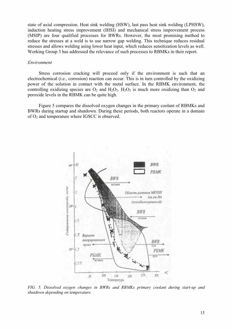
Stress corrosion cracking will proceed only if the environment is such that an electrochemical (i.e., corrosion) reaction can occur. This is in turn controlled by the oxidizing power of the solution in contact with the metal surface. In the RBMK environment, the controlling oxidizing species are O2 and H2O2. H2O2 is much more oxidizing than O2 and peroxide levels in the RBMK can be quite high.
Figure 5 compares the dissolved oxygen changes in the primary coolant of RBMKs and BWRs during startup and shutdown. During these periods, both reactors operate in a domain of O2 and temperature where IGSCC is observed.
FIG. 5. Dissolved oxygen changes in BWRs and RBMKs primary coolant during start-up and shutdown depending on temperature.

16
There are no measurements of the electrochemical potential (ECP), which quantifies the oxidizing ability of the RBMK coolant, but from the O2 and H2O2 data it could be concluded that it is way above the –230 mV (SHE) reported as a threshold above which the risk for IGSCC has to be considered.
Recent changes to operations have brought reactor water conductivities down to the 0.1 µS/cm levels consistent with western standards. High values of conductivity correlate
with high concentration of aggressive anions, specifically the strong acid anions, chloride and sulfate. Chloride intrusions from condenser leaks are recorded in most plants. In an analysis of the deposits on some pipe fracture surfaces, chlorine was found, with the highest amounts close to the crack tip. Laboratory studies have confirmed that chloride is a promoter of IGSCC in stainless steels. Sulfate is another, even more potent promoter of IGSCC, producing an almost tenfold increase in crack growth rate in BWR pipe material [46]. There are very few sulfate measurements from RBMKs, and it is believed that sulfate could enter the coolant with chloride during condenser leak incidents, as well as be a product of resin degradation.
Based on the discussion above, crevices must also be considered in the water chemistry analysis. In crevice geometries, the oxidizing nature of the RBMK will concentrate impurities like chloride and sulfate and change the water in the crevice to an acid pH. Under these severe localized conditions, IGSCC can initiate and propagate even in non-sensitized material if sufficient tensile stress is present.
Therefore, it can be concluded that RBMK water chemistry has generally been favourable to IGSCC. While it was not possible to discover any particular rate controlling factor, suspicions fall on the high oxidizing conditions during start-ups and the periods of high water conductivity both in the early operations of the plants, and today when condenser leaks occur [29]. Also, water chemistry and material effects (e.g., sensitization) have an interrelationship, with the water impurity effect being more pronounced for sensitized steels than for non-sensitized steels.
Decontamination processes have been implemented in all RBMK plants. There has been no link reported between decontamination methods applied in the RBMKs and the observed IGSCC phenomena.
Remedial actions adopted in the west include maintaining feedwater conductivity below 0.06 µS/cm, reducing chloride and sulfate impurity levels in the reactor water to 5 µg/kg each, and reducing the oxidizing environment (ECP) through additions of hydrogen and noble metals. The Working Group 4 report discusses the relevance of these approaches to the RBMK situation.
4.3. METALLURGICAL INVESTIGATIONS
Metallurgical investigations have confirmed that the cracking mechanism is IGSCC and sensitization is the primary material factor, but none of the investigations explain the roles of stress type or water chemistry components on crack initiation and growth rates. In fact, it is fair to say that absence of reliable IGSCC crack growth data for RBMK conditions severely hampers the ability to make recommendations on inspection intervals.

17
FIG. 6. Typical intergranular crack progression in the heat affected zone and appearance of the fracture surface.
Four types of metallurgical investigations have been undertaken with RBMK piping materials.
1. Metallographic examination of pipe sections containing cracks has revealed classic intergranular cracks in the course grain structure of the HAZ, in a narrow zone within 0.5 mm of the fusion line of the welds, Fig. 6. Some minor crack branching into the weld metal has been observed, but it seems that the crack does not have a tendency to continue growth solely in the weld metal.
Reports of studies of cracks in downcomer piping and group distribution headers from different reactors were reviewed. The majority of the intergranular cracks examined are 40–60 mm long and 5–12 mm deep. Some cracks have exceeded 100 mm in length (e.g., three at Ignalina Unit 1). The largest crack was found at Chernobyl Unit 3 and measured 350 mm in length and 10 mm in depth. These cracks are more open than typically has been observed in western reactor materials, perhaps indicating the release of high residual tensile stresses (50 µm for a 10 mm deep crack). The materials were most probably sensitized, as noted in Section 4.2, and the presence of grain boundary chromium carbides was reported, Fig. 3. Exposed fracture surfaces are clearly intergranular, Fig. 6.
This is irrefutable evidence that IGSCC is the operative mechanism of cracking in RBMK piping, and that material sensitization and high internal stresses are important factors in crack growth.

18
2. A large number of surveillance specimens have been exposed to RBMK environments for up to 200,000 hours. These specimens were of base metal and weld metal, both pre-cracked and un-cracked, and stressed and unstressed, yet in no case has any in-reactor crack growth been detected. Although it is difficult to draw any conclusions from this set of data, it is included here for completeness. Clearly, one or more of the three conditions needed for IGSCC is absent in these tests. On the one hand, it is tempting to argue that operational stress is the missing factor, given that the material and water chemistry conditions should be the same as those that the actual piping experienced. However, not enough information is available about the details of specimen fabrication history and their location in the circuit to rule out other factors. Such information could be very helpful in elucidating the root cause details. It must be noted that similar behaviour was observed in deflection loaded samples of heavily sensitized Type 304 samples exposed in US reactors. The explanation in this case was that stress relaxation occurred before crack initiation, as welded pipes in these reactors did crack during the same time period.
3. A few laboratory tests have been carried out on piping samples under a variety of conditions, from rupture tests on actual pipe sections to slow strain rate tests (SSRT) on samples cut from pipes taken out of service.
Slow strain rate tests on material from a welded downcomer pipe after 160,000 hours operation, tested either in the as received condition or after a heat treatment at 600 °Cfor 1 hour or 26 hours revealed IGSCC in plant aged material as expected. More results are also needed on the behaviour of the base material to confirm the original state of the material.
Crack growth rate date on stabilized stainless steels used in RBMKs is limited. Results obtained by Speidel and his colleagues from laboratory tests on stabilized stainless steels [47], analysis of existing operational experience available from German BWRs and Chernobyl NPP [48] as well as Chernobyl NPP base material data from [49] and Leningrad Unit 3 data (Appendix X [27]) show a weak dependency on stress intensity factor.
Other data indicate that crack growth varies according to a power law on stress intensity factor. While most of the data is on non-stabilized stainless steel, it has been reported by P. Andresen and R. Kilian [50] that there is not much difference in crack growth rates between non-stabilized and stabilized stainless steel, given the same metallurgical condition (sensitized or not, degree of sensitization, deformed or not, yield strength). With this relationship, the resulting crack growth rates can be much higher than 1 mm/year depending on stress intensity factor; the higher stress intensity factor, the greater the rate of growth. Clearly, more crack growth rate data on stabilized steel materials and further testing of RBMK stabilized steel piping welds and analysis of filed experience are needed to improve the date base and obtain both generic and plant (or unit) specific data on crack growth rate.
4. Results of DL EPR measurements preformed by NIKIET specialists in 2000 for the HAZ metal of flawed downcomer welds revealed higher EPR values in the weld HAZ with an IGSCC crack, while for the uncracked part of the weld root area, characteristic EPR values do not present sufficient deviation from those for the base metal. These data are presented in Table III.

19
TABLE III. DL EPR MEASUREMENT RESULTS
Weld section A (%) Base metal on the side with crack 0.17 HAZ with an IGSCC crack 3.1 Base metal on the crack free side 0.35 Crack free part of the HAZ 0.11
An additional study in 2001 using different techniques (DL-EPR and oxalic acid etching technique) on piping weld HAZ metal (taken from other plants), have confirmed these results. Results of both methods clearly show differences in metal state along the fusion line while moving from the inner to the outer surface.
4.4. CRACKING HISTORY EVALUATIONS
With a growing in-service inspection database, it should be possible to look at pipe cracking trends within a reactor over time, as well as trends across different reactors on the same site and trends across sites. Such a detailed analysis has not been completed.
FIG. 7. Scope of piping diameter 300 mm weld repairs at Kursk and Smolensk plants in 1997–2000.
Flaw data from Kursk and Smolensk NPP are shown in Fig. 7 as examples of the ISI experience. A flaw “location map” is presented for Ignalina Units 1 and 2 in Fig. 8.
It should be noted that accounting also for the number of welds and number of service years, the crack occurrence frequency could be somewhat different than expressed in the Figs 7 and 8a and 8b.
It is evident from the data that flaw indications are more prevalent in certain reactors, and that certain locations seem to be more susceptible to cracking (e.g., downcomers, group distribution headers). However, there seems to be no consistent pattern between plants. Downcomer flaws dominate the Ignalina NPP database, and very few flaws are found in group distribution headers. On the other hand, cracking experience in the piping system of the Russian plants tends to be less in the downcomers, but more in the group distribution headers. The explanation is that poor welding quality is the cause of the cracking in the piping system of their reactors. However, Kursk Unit 1 and Smolensk Unit 1 have experienced higher incidences of defects than other reactors on their sites and Leningrad Units 1 and 2 have not reported any defects to date in the downcomers. It is hard to believe that all these differences are due to the quality of the welding, and without a more detailed analysis other factors contributing to the cracking process cannot be identified.

20
43
3 6 4
102
13 93
35
8 2 00
20
40
60
80
100
120
WEP BC S D C PH-SH PP GD H
IGSCCWelding
WEP – Water equalising pipes PH-SH – Pressure Header – Suction Header BCS – Blowdown & Cooldown PP – Pressure pipes DC – Downcomers GDH Group Distribution Header
FIG. 8a. Unacceptable defects revealed in the diameter 300 mm piping of Ignalina Unit 1.
WEP – Water equalising pipes PH-SH – Pressure Header – Suction Header BCS – Blowdown & Cooldown PP – Pressure pipes DC – Downcomers GDH Group Distribution Header
FIG. 8b. Unacceptable defects revealed in the dia.300 mm piping of Ignalina Unit 2.
Therefore, at this time, the only conclusion that can be made from flaw indication data is that IGSCC is a generic problem for stabilised stainless steel piping in RBMK plants.
Flaw measurements after more than one cycle of reactor operation have been used to infer crack growth rates. This is an important quantity for establishing safe inspection intervals, and is the subject of a detailed discussion in Working Group 2 report. There is great experimental uncertainty in doing this but, by using averaged data since 1997, a maximum growth rate of 1 mm/year in the depth direction and 20 mm/year in the circumferential direction is inferred.
10
0
6
0
27
1 2 1
52 2
00
5
10
15
20
25
30
WEP BCS DC PH-SH PP GDH
IGSCCWelding

21
One example of potential non-conservatism, Fig. 9, shows a 4 mm deep crack in a repaired weld after two years of operation in an Ignalina unit; in other words, an average growth rate of 2 mm/year. This particular observation also calls for much more attention to be paid to weld repair conditions to minimize heat input, while ensuring proper fusion of the joints. Working Group 3 has examined weld repair techniques and the mechanical stress improvement process as a post weld repair treatment.
FIG. 9. Repaired weld (1998) with extensive root crack initiation and growth during two years of operation.
4.5. WATER CHEMISTRY
The RBMK water chemistry quality has improved over the past five years and current specifications and controls have been instituted to sustain, if not improve the water purity. Best practices today can maintain reactor water conductivity at or below 0.1 µS/cm, Fig. 10. However, it is important to note that RBMK water provides an oxidizing environment and the ECP is very likely to be conducive to crack growth. Worsening this situation is the presence of relatively high copper concentrations in the feed water (from condensers) and the occurrence of chloride (and possibly sulfate) excursions due to condenser leaks and/or insufficient make-up water treatment.
The interaction of crevices and water chemistry in the RBMK environment must also be considered. As noted earlier, the elevated impurity concentrations and potential gradient existing in a crevice can initiate IGSCC in an otherwise resistant material. Consequently, while any specific chemistry cause for the observed IGSCC cannot be pinpointed, suffice it to say that the chemistry conditions are generally favourable for IGSCC, given a sensitized material and sufficient stress (residual or operational).
Because of this concern, additional attempts are being made to reduce the corrosive nature of the reactor coolant. As reported by Working Group 4, a deaeration process has been tested in RBMKs to reduce oxygen levels during preoperational testing and startups. Results are sufficiently encouraging to recommend its routine adoption by all plants. Online chemistry monitoring is being used to catch condenser leaks early and repair them before too much chloride leaks into the feedwater. It is also recommended that sulfate and chloride specifications be set at 5 µg/kg, as a maximum value for both these ions in the reactor water and that feedwater conductivity specifications be set at 0.065 µS/cm. Finally, a pilot test of the Studsvik ECP probe in one of the Ignalina reactors will determine the value of this type of measurement to monitor the corrosion potential of the reactor coolant on a continuing basis and, therefore provide the ability to determine in-reactor crack growth rates from laboratory data.

22
FIG. 10. RBMK versus BWR mean reactor water conductivity.
Nevertheless, despite all these helpful additions to the water chemistry control program, it must be noted that a similar program instituted for BWRs did not totally eliminate occurrence of cracking. It was finally concluded that even the highest possible water quality will not provide immunity to IGSCC. The same is likely to be true for RBMKs, in which case more extreme measures must be considered to ensure long term operation without pipe cracking. The Working Group 4 report discusses possible use of hydrogen water chemistry, noble metal and aluminium chemical application in RBMKs [29].
5. GENERAL CONCLUSIONS AND RECOMMENDATIONS
Major results of the work of this Programme are provided in this section. Section 5 is structured to focus on: 1. in-service inspection; 2. flaw assessment to establish inspection intervals; 3. pipe repair technologies; and 4. other IGSCC mitigation strategies, in particular stressing plant chemistry [26–29]. Inasmuch as RBMK owners and their research and engineering support groups have been working in parallel to implement techniques and processes to mitigate the cracking problem, it is also important to describe the status of that implementation, and the gaps remaining that must be filled to assure continued safe and reliable operation of these plants.
5.1. IMPROVED IN-SERVICE INSPECTION
Nondestructive in-service inspection is a highly skilled diagnostic technology whose goal is to detect any degradation mechanism that would compromise the integrity of the primary pressure boundary and compromise the function of safety engineered systems. The focus of the work has been to improve the quality and reliability of ISI at RBMK plants.

23
5.1.1. Manual ultrasonic inspection techniques
Through the support of the US International Nuclear Safety Program (INSP), Working Group 1 presented two courses on manual inspection techniques. RBMK ultrasonic specialists were provided procedures and training in manual ultrasonic inspection techniques that successfully completed performance demonstrations required under the American Society of Mechanical Engineers Section XI, Appendix VIII. The procedures provided to the Programme participants included:
a manual inspection procedure for detection of IGSCC cracks; a manual inspection procedure for characterizing the through-wall extend and circumferential length of IGSCC cracks; a manual procedure for ultrasonic inspection of welds repaired using overlay technology.
Results from the pilot study conducted following the training courses support the conclusion that the manual ultrasonic inspection techniques were transferred effectively under the IAEA Programme.
Based on the detection performance of inspectors participating in the pilot study, the Working Group concluded that
The manual ultrasonic inspection techniques transferred under the IAEA Programme are appropriate for detecting IGSCC in RBMK reactors. The reliability of detection performance of ISI specialists at RBMK power plants can be equivalent to detection performance achieved at Western power plants.
The performance of pilot study participants with respect to length and depth sizing of flaws indicates that:
The manual sizing techniques transferred under the IAEA Programme are appropriate for characterizing IGSCC in RBMK reactors. Although 8 of 11 inspectors meet ASME acceptance criteria, it is evident from the sizing data that all the inspectors could use additional practice in depth sizing.
The status of implementation of the manual inspection procedures is as follows:
The sizing procedure was adapted for RBMK plants by Ignalina plant staff and was used during the routine inspection at the plant during the 2001 outage. Ignalina plant staff reported that destructive analysis of defects that were sized using the procedure showed that ultrasonic measurements within ±2 mm of actual crack height for cracks with depths ranging from 2 to 10 mm. Ignalina plant staff reported that the transducers specified in the adapted procedure had limitations for welds with weld crowns that were 30 mm or greater. Ignalina plant staff plan to update the procedure requirements for transducer sizes and configurations prior to submitting the procedure for approval for general plant use.
NIKIET indicated that the available Russian manual inspection procedures are adequate and did not adapt the manual ultrasonic detection procedure was provided. Representatives from the Russian Federation provided a brief presentation on semi-automatic ultrasonic procedures that have been developed in Russia Federation. The

24
information presented by Russian Federation indicated the technology is good. No information similar to the pilot study was made available that allowed members of the working group to conclude how well the technology performed when used by several different inspectors from different RBMK power plants. Also, no information was made available that showed the state of practice on manual ultrasonic procedures. Therefore, no conclusions can be stated concerning the reliability of Russian detection procedures as practiced at RBMK power plants. NIKIET did state that Russian Federation would adopt weld overlay inspection techniques and requested assistance in reviewing the inspection procedure. However, Russian participants did not provide an inspection procedure for review. Russian specialists indicated that a weld overlay inspection procedure would be developed and is scheduled to be completed during the next year. It was agreed at the Working Group level to review the weld overlay procedure, as part of the continued co-operation between members of the Working Group even after completion of the IAEA Programme.
Ukrainian participants concluded that all the inspection techniques presented during the seminar were useful. They are in the process of adapting all the procedures to conform to Ukrainian requirements and submitting the adapted procedures for approval by Ukrainian regulatory authorities.
5.1.2. Development of qualification criteria for ultrasonic inspection
A draft qualification document was developed based upon the IAEA report, Methodology for Qualification of In-Service Inspection Systems for WWER Nuclear Power Plants, IAEA-EBP-WWER-11 [51]. The pilot study helped to provide data that supported criteria specified in the draft qualification document. Data from the pilot study also indicate that cracks with a through wall depth of 25% (4 mm) have approximately an 80% probability of detection. This tends to support the criteria in the draft qualification document for a target flaw size of 4 mm.
The draft qualification document does not contain specific acceptance criteria that are needed for successful implementation of the process.
It is therefore recommended that countries operating RBMK reactors complete the development of a qualification document and qualification process. This is necessary to ensure that the reliability of in-service inspection is adequate to detect and characterize IGSCC that would compromise the integrity of the primary pressure boundary. Russian specialists suggest that while qualifying the inspection procedures, the ability to reveal IGSCC type cracks of different opening (from 2 to 50 µm) should be estimated, which is very important for evaluating the error in the size measurements made by the ultrasonic testing method.
5.1.3. Recommendations
1. The experience gained in the series of seminars conducted under this Programme demonstrated the importance of regular training classes to ensure that inspectors maintain, if not enhance their skills. Therefore, it is recommended that countries operating RBMK reactors develop training materials and conduct training classes specific to the ultrasonic procedures used to detect and characterize IGSCC. The training courses should include both theoretical and practical exercises. Specimens with

25
the relevant real structure of welded joints, which have defects of the IGSCC induced crack type, should be used.
2. Members of the working group felt that a regular annual or bi-annual exchange of information between Western and former Soviet Union experts in plant ISI would be very useful. The group developed the following list of topics for such exchanges.
An exchange of information on ISI procedure and personnel qualification approaches and acceptance criteria, including an evaluation of probability of detection compared probability of non-detection; An exchange of information on bi-metallic weld inspection including specific procedure requirements that are currently used and an exchange on the status of developing methodology such as phased arrays; An exchange of information on axial crack inspection; An exchange on advanced areas of ISI for power plants; and An exchange of information on erosion/corrosion programs including causes, mitigation and ISI monitoring.
3. Members felt that collaboration in development of flaw evaluation criteria for austenitic welds is important, especially for the continued operation of both RBMK and WWER power plants.
4. Members felt that an exchange of engineers between power plants would be very useful. 5. Members felt that a review of the assumptions in probability of detection (POD) used in
the risk based approach of Working Group 2, specifically flaw orientation, flaw length and degradation mechanism, would be beneficial.
5.2. FLAW ASSESSMENT AND IMPACT ON INSPECTION REQUIREMENTS
5.2.1. Flaw assessment methods
A number of national flaw assessment methods have been investigated and compared. Most countries are using “net section collapse” or the “R6 method” or combinations of these two procedures. Disregarding the crack growth rate, most national flaw assessment methods will give similar results regarding acceptable and critical crack sizes. Based on the benchmark results, any one of the national procedures is judged to give an adequate result. However, it is noted that if a crack with unknown depth has been detected, continued operation without repair is allowed for one year in Russian Federation and Lithuania using their respective national flaw assessment procedure. In Russian Federation, however, such a decision is possible only for short length defects for which a leak before break scenario is most likely.
5.2.2. Crack growth rates
Upper bound data for IGSCC crack growth rate is needed to establish adequate target flaw sizes for inspections, as well as appropriate inspection intervals to ensure safe operation. In the context of this report, “target flaw size” is the smallest defect that can be reliably detected by a qualified inspection system. Basically, in Russian Federation a constant crack growth rate of 1 mm per year in depth, regardless of the stress condition, is being used, whereas most other countries are advocating a K dependent crack growth rate. This raises a concern that a non-conservative growth rate is being used in Russian Federation, in the absence of any adequate experimental data on growth rate. The available information can be summarised as follows:
1. It is reasonable to suppose that the defect growth rate in stabilised stainless steels in RBMK conditions is less than the ‘Swedish curve’ [52] describing unstabilized steel

26
growth rates. Until more information is collected, it is recommended to use the growth rate described by this equation, namely,
da/dt = 4.5 × 10⁻¹² KI3mm/s (1)
This curve is derived from an international compilation of growth rate for unstabilized steels from several companies. The equation also bounds data obtained by Speidel and Magdowski [49] on specimen’s representative of Chernobyl Unit 3.
2. It seems physically reasonable that the growth rate has some dependence upon K. This is also supported by data for stabilised stainless steels reported by Hickling et al. [53]. However, scatter in observed data is large for IGSCC. It is possible to encompass empirical data with a uniform growth rate curve and this is sometimes done. The advantage of using a K dependent growth rate is that both the crack size and stress state will have an influence on the growth rate and thus one will have a system that automatically gives shorter inspection intervals for high stressed welds or larger target flaw sizes. This also means that the inspection interval is dependent on the detection capability of the inspection method used.
3. The MINATOM specialists’ opinion is as follows: The results of repeated in-service inspections of a large number of welded joints in real NPP conditions have confirmed the conservatism of crack growth rates used in Russian Federation (1 mm per year in the depth direction and 20 mm per year in the circumferential direction). These crack growth rate values are applied only for evaluation of IGSCC affected welds that have been present since the start of operation. Annual inspection and re-evaluation is required for welds in which flaws have been detected but evaluated as allowable and left in place. Defects detected in repaired welds and related high crack growth rates are connected to violation of welding procedures during repair welding. Such welds shall be repaired immediately (no defect allowability analysis is permitted).
4. The effects of water chemistry on growth rates and some water chemistry parameters themselves (e.g. during transients, startups, etc.), within RBMKs are not well known. It is not possible to comment on whether this could cause a greater variability in growth rates than that expressed by the Swedish curve or the empirical data. Of particular note is the lack of data on electrochemical potential especially during transients (start-ups, etc.).
5.2.3. Recommended inspection requirements
Based on the foregoing discussions, the following recommendations are made regarding inspection requirements:
1. Attempts should be made to perform inspection qualification (performance demonstration) on defects, covering a range of flaw sizes justified by the necessary inspection intervals from the flaw assessment procedures.
2. Welds that have been subject to repair should initially be inspected yearly, at least until evidence is available that no new cracking is occurring in repaired welds.
3. Cracked welds left without repair should be inspected yearly. However, if adequate inspection qualification procedures have been developed for sizing detected flaws both in length and depth, and if appropriate stress and crack growth rate data are available,

27
fracture mechanics methods may be used to determine a more precise relationship between defect sizes that can be left without repair and a suitable future inspection interval to provide sufficient plant safety.
4. For IGSCC susceptible welds where no defects have yet been detected, we recommended inspection of all welds. The determination of the inspection intervals should be carried out using a procedure based on fracture mechanics that allows for defect growth. However in this case, it is necessary to establish the target flaw size, pipe stresses and the crack growth rate for the component.
For example, if an upper estimate of crack growth rate can be established such as equation (1) in Section 5.2.2 and if the target flaw size, detectable by a qualified procedure, is 4 × 60 mm (Working Group 1 recommendation), then the majority of the Working Group 2 benchmark solutions revealed that:
an inspection interval of four years is adequate for low or moderately stressed welds;an inspection interval of one year is adequate for high stressed welds.
Thus the use of the flaw evaluation procedure can give a more precise relationship as well as provide the distinction between a low stressed and a high stressed weld.
The above scheme gives a strong driving force to establish better information. More benefit will derive from better knowledge of the plant data and inspection capabilities.
5. To allow the use of the flaw evaluation procedure to determine the inspection interval, a programme to measure crack growth rates on stabilised stainless steels should be implemented. This should take into account experience obtained on NPPs but also include measurements made under laboratory controlled conditions. Proper account should be taken of water chemistry conditions and actual levels of sensitization and deformation. Additionally, verification of pipe stresses, either by detailed stress analysis that accounts for the as built information of pipe systems, or by using a load monitoring system, should be performed.
5.2.4. Radiation dose issues
It is a concern that the overall radiation dose burden being experienced is large, as is the financial cost, and therefore it is necessary to minimize both while maintaining adequate assurance of safety. As part of a wider programme to reduce radiation exposure to inspection personnel, it is recognized that risk based inspection (RBI) procedures could be a valuable tool for defining an inspection programme that connects the inspection requirements and inspection intervals with quantitative measures of plant safety. However, implementation may require a level of plant information and accuracy of data that may not exist for all RBMKs. Also, regulatory acceptance of a RBI procedure for RBMKs does not yet exist. Additionally, wider use of automated inspection and repair methods (and western decontamination processes with higher decontamination factors) could contribute to reduced radiation doses for plant workers.
5.2.5. Leak before break considerations
“Classical” leak before break (LBB) is not applicable for RBMK austenitic piping when IGSCC is the active damage mechanism. Classical LBB means in this context a procedure for which a simple through-wall crack is postulated in a pipe section and which is then

28
demonstrated to fulfil certain safety margins. It is thus possible to avoid the installation of pipe whip restraints to protect against dynamic effects during a pipe rupture. The purpose of investigating LBB in RBMK austenitic piping when IGSCC is the active damage mechanism is to demonstrate that an adequate safety margin exists against rupture if cracks are missed during inspections, or if inspections are not possible (for example due to inaccessible regions). Further work should be performed to develop a procedure to demonstrate a sufficiently small probability of double ended guillotine break. In this context, the following aspects should be considered:
complex crack shapes that imply an extensive crack length in the circumferential direction and a through wall crack for part of the circumference`; consideration of all relevant loadings both at normal operating conditions including residual stresses and possible vibration stresses (for flaw growth analysis) and at test/emergency or faulted/accident conditions (for determination of critical crack sizes) evaluation of leak rates with proper account of complex crack shapes and loading situations including weld residual stresses in relation to leak detection capabilities; use of probabilistic fracture mechanics procedures as an additional source of information supporting LBB arguments or possibly as a complete alternative LBB procedure. However, no regulatory procedure has been developed yet covering this situation.
Developed LBB procedures should be validated against appropriate and relevant analytical and experimental data.
5.3. PIPE REPAIR AND MITIGATION METHODS
The root cause studies (Section 4) have identified material sensitization and high residual weld tensile stresses as two of the causes of IGSCC. Accordingly, the emphasis here has been on methods to reduce these factors in the weld and post weld treatment process.
5.3.1. Optimization of repair welding technology
The US technology for low stress welding techniques, heat sink welding and narrow groove GTAW (automated argon arc welding with non-fusible electrode) welding was transferred to RBMK operators. A welding workshop was held in Charlotte, NC, at the Electric Power Research Institute (EPRI) centre to transfer the GTAW technologies for repair and mitigation of pipe cracking associated with IGSCC. The workshop was attended by Russian and Lithuanian welding experts. These methods will provide a reduction of both material sensitization and weld residual stresses. Suppliers of such equipment are available in Russian Federation, France, the United States and other countries. Russian experience also shows the benefit of heat sink welding for reduction of weld residual tensile stresses at the weld root. These findings are consistent with the finding of the US BWR plants. However, a proposed technology still uses weld root without filler metal. This is discouraged in the USA, for the following reasons.
Austenitic stainless steel welds are susceptible to hot cracking or microfissuiring as they cool from the solidus to about 980°C (1800°F). Microfissuires can be prevented or kept to a minimum by eliminating or reducing tensile stresses imposed on the weld during cooling in this range. Reducing residual elements, such as phosphorus, also assists in minimizing microfissuiring to a limited degree. The most common method to control microfussuiring is to ensure the presence of at least 3–4% ferrite in the as-deposited weld. Small amounts of this

29
phase prevent the cracking that often occurs in fully austenitic weld metal, such as when stainless steels are welded without filler metal. It should also be noted that results from corrosion studies performed by EPRI and other researchers has shown that a small percentage of ferrite, between 5 to 8%, is very effective in reducing the susceptibility to stress corrosion cracking.
5.3.2. Weld overlay repair
The use of weld overlays for the repair of welds containing IGSCC cracks in 300 mm diameter pipes is recommended. Appropriate inspection procedures and intervals, such as those discussed in Section 5.1 of this report, should be established. There is a suitable technical basis available in ASME Codes and US NRC documentation to justify overlay application. Equipment type and availability to perform welding overlays is similar to that described in Section 5.3.1. Furthermore, there are sufficient models and modelling technologies available to evaluate the stress distributions. The final overlay design could be modified based on the service life of the overlay, size of the flaw, and the applied loading of the piping systems. The technical infrastructure in Russian Federation allows the transfer of this technology to RBMKs.
Further work is recommended in: establishment of design margins, application of coolant filled pipes and software to ease the design of the overlay and justification of long term operation. Assessment of the effects of sensitization to the pipe caused by the weld overlay, selection of optimal solutions on welding equipment and processes and finalization of welding procedures are also recommendations for the future.
5.3.3. Qualification of mitigation techniques
MSIP as an acceptable mitigation technology is recommended. To eliminate the potential for this process to drive pre-existing deep cracks through the pipe wall, it shall only be applied to crack free welds. The effort to qualify MSIP in Russian NPPs has been transferred to an INSP activity. The INSP is working to provide qualified methods, tooling and personnel and will deliver six sets of equipment to Russian Federation in 2002. It will be appropriate to reassess inspection intervals once mitigation techniques are successfully implemented in the plants.
5.4. OTHER IGSCC MITIGATION STRATEGIES
The following recommendations address the environmental component of IGSCC.
5.4.1. Adequate monitoring of anions / action levels in reactor water
Now that every RBMK plant has in-line chemistry monitoring systems and laboratory chromatography equipment, regular measurements of chloride and sulfate in reactor water should be made part of the plant water chemistry specifications. Chloride and sulfate in reactor water should be maintained at 5 µg/kg for each ion and plant action levels should be instituted if these levels are exceeded.
5.4.2. Water chemistry monitoring systems
The in-line water chemistry monitoring systems, chromatography equipment and automatic data acquisition systems should be made the centrepiece of formal water chemistry

30
programs at all plants. This should include standardized procedures, training programs, certification of technicians and management oversight. Data should be collected regularly and analyzed promptly to assure adherence to plant specifications and quick remedial action taken if limits are exceeded. A philosophy of “High quality water chemistry all the time” must be promulgated by plant management from the top of the organization down to the lowest levels. It is understood that such a programme is now in place at several RBMK plants.
5.4.3. General quality of feed water
While RBMKs have made progress in improving their water chemistry and now typically measure reactor water conductivities in the range of 0.1 µS/cm, it is recommended that a goal of further reducing conductivity below 0.065 µS/cm can be established. Conductivity transients continue due to condenser leaks and/or insufficient make-up water quality. The high conductivities observed are due to increased levels of chloride, sulfate and other ionic or organic species. Such transients can be very deleterious to materials, causing crack growth far beyond the duration of the transient. Therefore, condenser monitoring, leak detection and remedial actions should be re-evaluated to determine if there are ways to reduce the probability of incurring tube leaks and/or reduce the recovery time following leak detection.
All RBMKs are reported to have full flow condensate polishing systems consisting of a deep cation bed followed by a mixed anion–cation bed. It is recommended that a study be made of ways to improve the operational efficiency of these beds for sulfate and chloride removal by using the regular bed cleaning methods and choice of resins similar to those used in BWRs. Also, conversion of the cation bed to a mixed bed should be evaluated.
5.4.4. Deaeration
Deaeration should be considered as a standard reactor start-up procedure for RBMKs to reduce oxygen levels in the coolant during critical operational periods. While western experience with BWRs does not show major reductions in IGSCC susceptibility from this technique, we believe that RBMK operators should take every opportunity to reduce the oxidizing potential of the reactor water in critical temperature regions.
5.4.5. ECP measurements
The plan to measure electrochemical potential in the Ignalina NPP using the Studsvik electrodes and procedure is fully endorsed. It is essential to gain knowledge of the “corrosivity” of typical RBMK coolant at various places, and this pilot program should provide some of the necessary data. If successful, consideration should be given to making additional measurements of ECP in other plants. It is understood that a system has been developed for Russian reactors, but has not yet been approved for use. If direct ECP measurements are not feasible, the Ignalina data can be used together with in-plant measurements of H2O2, H2 and O2 already available from Russian plants to calibrate a model that can be used to predict ECP to some extent in the plants. Both Sweden and the U.K. have radiolysis codes that predict concentrations of H2, O2, H2O2 and other labile hydrogen–oxygen species in the various parts of BWRs. Based on these analyses, ECP values in many relevant regions can be estimated for evaluating IGSCC potential. It might be feasible to adapt such codes to RBMK 1000 and 1500 plant conditions.

31
5.4.6. Decontamination processes
Higher decontamination factors, of 10 or more, produced without any increased susceptibility to IGSCC, can be achieved by several decontamination processes now used routinely in the west. It is therefore recommended that RBMK operators evaluate these techniques, in particular CORD, LOMI and CANDEREM, for application to their plants. If introduced into RBMKs, they would both reduce radiation fields and increase the time between decontaminations. A detailed analysis should take into account features of the RBMK cooling system and the amount of active waste expected. Since it is not feasible to remove RBMK fuel before decontamination, and leaving it in would result in unacceptable quantities of waste, consideration needs to be given to “valving” out the core region.
Western BWRs have successfully combined piping system decontamination with the implementation of isotopically depleted zinc injection to reduce recontamination and shutdown dose. If zinc injection and decontamination are coordinated in RBMKs, it might be possible to reduce the number of decontaminations needed.
5.4.7. Replacement of copper alloys
Because of the regular tube leakage in the copper alloy condensers and the relatively high copper concentration in the reactor water, their continued use should be reevaluated. An economic argument can probably be made for replacement of the condensers in newer plants, in which case stainless steel or titanium tubes should be considered. Elimination of copper alloys would have the dual effect of increasing integrity and eliminating in leakage of chlorides etc., as well as reducing copper in the reactor water. A detailed cost benefit analysis is necessary for plants nearing the end of their design lifetime prior to any decision to replace plant components.
5.4.8. Implementation of alternative water chemistries
Given the western experience, even with material and stress remedies successfully introduced, IGSCC is still likely even in the low oxygen, low conductivity RBMK environment. Therefore, it is recommended that alternative water chemistries be considered. The two established approaches are hydrogen water chemistry (HWC) and noble metal chemical additions (NMCA) The NMCA process appears to be more compatible with current RBMK conditions. NMCA works even with high copper concentrations in the reactor water, and the lower hydrogen needs of NMCA can be satisfied with on site hydrogen production. Additionally, zinc injection should be made a part of such a plan to achieve lower dose rates (factor of 10 reduction in BWRs). In considering this recommendation, the unique features of the RBMK main cooling system configuration and the impacts on N-16, Co-60 formation and hydrogen safety should all be taken into account.


33
Appendix I
SUMMARY REPORTS OF THE WORKING GROUPS
This appendix summarizes the final reports of the four working groups [26–29].
A.I.1. WORKING GROUP 1 — IMPROVEMENTS IN IN-SERVICE PERFORMANCE AND QUALIFICATION
A.I.1.1. Objectives
Task 1. Transfer improved ultrasonic inspection techniques for flaw detection and characterization
The objective of this task was to transfer ultrasonic inspection techniques to RBMK ISI specialists that will improve the reliability of detection and characterization of cracks in the main coolant piping. The four activities to accomplish this objective were:
conduct a seminar at the Smolensk nuclear power plant to begin the process of transferring manual ultrasonic inspection techniques; develop an improved inspection procedure for detection of cracks in RBMK reactors; develop an improved inspection procedure for characterizing the extent through, and circumferential length of cracks in RBMK reactors; develop a procedure for ultrasonic inspection of welds that are repaired using overlay technology.
Task 2. Development of performance demonstration criteria for ultrasonic inspection
The objective of this task was to develop practical performance demonstration criteria for ultrasonic inspection of austenitic welds in RBMK reactors. To accomplish this objective, a qualification process for manual ultrasonic inspection of 300 mm main coolant piping was developed.
A.I.1.2. Approach
The objectives of Task 1 were accomplished by conducting four seminars. The seminars were sponsored by the US Department of Energy’s International Nuclear Safety Program. Three of the seminars were conducted at RBMK nuclear power plant sites: Smolensk, Leningrad and Ignalina respectively. The fourth seminar was conducted at the VNIIAES, institute in Moscow. A detailed report on each of the seminars, including the syllabus and participants comments on the seminar was prepared [32, 34, 37, 43]. The working language for all the seminars was Russian. Approximately 40% of the material was taught directly in Russian; the remainder was taught in English and translated into Russian. The participants received binders containing all training material (Refs [31, 33, 36, 42]).
Participants in the seminar were specialists from nuclear power plants who were actually involved in the in-service inspection of primary circuit welds. A well-rounded group with a high degree of professional knowledge was formed. All of the participants had hands on skills in ultrasonic testing and a good understanding of ultrasonic testing. Some of the course participants had experience in automated ultrasonic testing. Operation of modern

34
testing equipment (digital ultrasonic instruments USN 52, USN 60 and Panametrics Epoch 3) presented no difficulties to the group. The majority of the participants were familiar with problems arising from IGSCC detection and sizing.
During the seminars the course participants were familiarized with current western manual ultrasonic inspection techniques applied to IGSCC detection and signal characterization. All the techniques that were taught to the participants had been used successfully in performance demonstrations required under the American Society of Mechanical Engineers Section XI, Appendix VIII. At the end of each seminar a written and practical test was administered to assess effectiveness of the instruction process. The test results were generally very good, indicating a high degree of successful information transfer. All the seminars received very positive feedback from the participants in the course.
For Task 2, a draft qualification document was developed. The topical outline found in the IAEA report Methodology for Qualification of In-Service Inspection Systems for WWER Nuclear Power Plants, IAEA-EBP-WWER-11 [51], was used as a basis for the qualification document. The technical content in the initial draft was based upon performance demonstration practices that have been developed in Europe through ENIQ, in the United Kingdom through validation trials and in the United States through the American Society for Mechanical Engineers (ASME) Section XI and the Performance Demonstration Initiative managed by the Electric Power Research Institute (EPRI). The draft document does not contain specific criteria for successful completion of the qualification.
A.I.1.3. Conclusions and recommendations
Manual ultrasonic inspection techniques
1. Through the support of the US International Nuclear Safety Program, Working Group 1 presented two courses on manual inspection techniques. RBMK ultrasonic specialists were provided procedures and training in manual ultrasonic inspection techniques that successfully completed performance demonstrations required under the American Society of Mechanical Engineers Section XI, Appendix VIII. The procedures provided to the Programme participants included.
A manual inspection procedure for detection of IGSCC cracks; A manual inspection procedure for characterizing the through-wall extend and circumferential length of IGSCC cracks; A manual procedure for ultrasonic inspection of welds repaired using overlay technology.
2. Results from the pilot study conducted following the training courses support the conclusion that the manual ultrasonic inspection techniques were transferred effectively under the IAEA Programme.
3. Based on the detection performance of inspectors participating in the pilot study, the Working Group concluded that
The manual ultrasonic inspection techniques transferred under the IAEA Programme are appropriate for detecting IGSCC in RBMK reactors. The reliability of detection performance of ISI specialists at RBMK power plants can be equivalent to detection performance achieved at Western power plants.

35
4. The performance of pilot study participants with respect to length and depth sizing of flaws indicates that
The manual sizing techniques transferred under the IAEA Programme are appropriate for characterizing IGSCC in RBMK reactors. Although 8 of 11 inspectors meet ASME acceptance criteria, it is evident from the sizing data that all the inspectors could use additional practice in depth sizing.
5. The status of implementation of the manual inspection procedures is as follows:
The sizing procedure was adapted for RBMK plants by Ignalina plant staff and was used during the routine inspection at the plant during the 2001 outage. Ignalina plant staff reported that destructive analysis of defects that were sized using the procedure showed that ultrasonic measurements within ± 2 mm of actual crack height for cracks with depths ranging from 2 to 10 mm. Ignalina plant staff reported that the transducers specified in the adapted procedure had limitations for welds with weld crowns that were 30 mm or greater. Ignalina plant staff plan to update the procedure requirements for transducer sizes and configurations prior to submitting the procedure for approval for general plant use.
NIKIET indicated that the available Russian manual inspection procedures are adequate and did not adapt the manual ultrasonic detection procedure was provided. Representatives from Russian Federation provided a brief presentation on semi-automatic ultrasonic procedures that have been developed in Russian Federation. The information presented by Russian Federation indicated the technology is good. No information similar to the pilot study was made available that allowed members of the working group to conclude how well the technology performed when used by several different inspectors from different RBMK power plants. Also, no information was made available that showed the state of practice on manual ultrasonic procedures. Therefore, no conclusions can be stated concerning the reliability of Russian detection procedures as practiced at RBMK power plants. NIKIET did state that Russian Federation would adopt weld overlay inspection techniques and requested assistance in reviewing the inspection procedure. However, Russian participants did not provide an inspection procedure for review. Russian specialists indicated that a weld overlay inspection procedure would be developed and is scheduled to be completed during the next year. It was agreed at the Working Group level to review the weld overlay procedure, as part of the continued co-operation between members of the Working Group even after completion of the IAEA Programme.
Ukrainian participants concluded that all the inspection techniques presented during the seminar were useful. They are in the process of adapting all the procedures to conform to Ukrainian requirements and submitting the adapted procedures for approval by Ukrainian regulatory authorities.
Development of qualification criteria for ultrasonic inspection
6. A draft qualification document was developed based upon the IAEA report, Methodoly for Qualification of In-Service Inspection Systems for WWER Nuclear Power Plants, IAEA-EBP-WWER-11 [51]. The pilot study helped to provide date that supported criteria specified in the draft qualification document. Date from the pilot study also

36
indicate that cracks with a through wall depth of 25% (4 mm) have approximately an 80% probability of detection. This tends to support the criteria in the draft qualification document for a target flaw size of 4 mm.
7. The draft qualification document does not contain specific acceptance criteria that are needed for successful implementation of the process. It is therefore recommended that countries operating RBMK reactors complete the development of a qualification document and qualification process. This is necessary to ensure that the reliability of in-service inspection is adequate to detect and characterize IGSCC that would compromise the integrity of the primary pressure boundary. Russian specialists suggest that while qualifying the inspection procedures, the ability to reveal IGSCC type cracks of different opening (from 2 to 50 µm) should be estimated, which is very important for evaluating the error in the size measurements made by the ultrasonic testing method.
Future activities
8. The experience gained in the series of seminars conducted under this Programme demonstrated the importance of regular training classes to ensure that inspectors maintain, if not enhance their skills. Therefore, it is recommended that countries operating RBMK reactors develop training materials and conduct training classes specific to the ultrasonic procedures used to detect and characterize IGSCC. The training courses should include both theoretical and practical exercises. Specimens with the relevant real structure of welded joints, which have defects of the IGSCC induced crack type, should be used.
9. The members of Working Group 1 strongly recommend that consideration be given to the following topics for future collaboration:
(a) Members of the working group felt that a regular annual or bi-annual exchange of information between Western and soviet experts in plant ISI would be very useful. The group developed the following list of topics for such exchanges.
An exchange of information on ISI procedure and personnel qualification approaches and acceptance criteria, including an evaluation of probability of detection compared probability of non-detection; An exchange of information on bi-metallic weld inspection including specific procedure requirements that are currently used and an exchange on the status of developing methodology such as phased arrays; An exchange of information on axial crack inspection; An exchange on advanced areas of ISI for power plants; and An exchange of information on erosion/corrosion programs including causes, mitigation and ISI monitoring.
(b) Members felt that collaboration in development of flaw evaluation criteria for austenitic welds is important, especially for the continued operation of both RBMK and WWER power plants.
(c) Members felt that an exchange of engineers between power plants would be very useful.
(d) Members felt that a review of the assumptions in POD used in the risk based approach of Working Group 2, specifically flaw orientation, flaw length and degradation mechanism, would be beneficial.

37
A.I.2. WORKING GROUP 2 – COMPREHENSIVE ASSESSMENT TECHNIQUES
A.I.2.1. Objective
The following four main objectives have been formulated for Working Group 2:
1. To recommend a break preclusion procedure based on ISI results that can form the basis for decisions for safe operation until the next inspection.
2. To recommend target sizes for flaws that need to be detected during ISI depending on the inspection interval.
3. To improve the understanding of the root cause and cracking mechanisms of IGSCC in RBMK plants.
4. To exchange and transfer knowledge on risk based inspection procedures that can be relevant for RBMK plants.
A.I.2.2. Approach
The following four Tasks were developed:
Task 1. Damage database
Collect data of occurred damage to guide the inspection locations and help understand under what circumstances IGSCC is occurring in RBMK plants (root cause). A detailed damage database is important to be able to perform probabilistic evaluations that may help find the high risk locations for high priority inspections.
Task 2. Break preclusion methodology
Develop procedures to assist the decisions to be made when an actual defect is detected. The procedure shall give guidance when a repair/replacement can be recommended and when the flaw can be left for continued safe operation. The procedure shall, in this case, give guidance on the inspection interval. The procedure shall also be able to set the target flaw size coupled with the inspection interval for an inspection program for potential sites of IGSCC. Task 2 also explores the possibilities to use leak before break procedures for the relevant RBMK piping systems.
Task 3. Root causes of IGSCC in RBMK plants
Information shall be collected in order to determine cracking mechanisms during both initiation and propagation of stress corrosion cracks in stabilised stainless steels. Understanding the root cause of IGSCC in RBMK plants will help determine cost effective mitigation activities.
Task 4. Risk based inspection pilot study for Ignalina Unit 2
This will use modern RBI technology to perform a pilot study for Ignalina Unit 2 for IGSCC susceptible locations in stainless steel piping systems. The outcome of the pilot study will be a recommendation of a new inspection programme where more inspection efforts are directed to components having higher risk for core damage. The pilot study is part of a special contract between DNV and Ignalina plant with SIP Sweden, which funded the work.

38
A.I.2.3. Conclusions and recommendations
The work within Working Group 2 has resulted in the following conclusions and recommendations:
Damage database
1. It is essential to create a detailed damage database for each RBMK plant that contains relevant information of IGSCC events. Such databases will give valuable information regarding (for example) root causes of IGSCC, inspection capabilities and crack growth rates. Furthermore, a good damage database is required in order to optimise the inspection programme. Within the timeframe of Working Group 2, only Ignalina plant has created a local damage database that contains sufficient information for this project.
Flaw assessment methods
2. A number of national flaw assessment methods have been investigated and compared. Most countries are using net section collapse or the R6 method, or combinations of these two procedures. Disregarding the crack growth rate, most national flaw assessment methods will give similar results regarding acceptable and critical crack sizes. Based on the benchmark results, any one of the national procedures is judged to give an adequate result. However, it is noted that if a crack with unknown depth has been detected, continued operation without repair is allowed for one year in Russian Federation and Lithuania, using their respective national flaw assessment procedures. In Russian Federation, however, such a decision is possible only for defects short in length for which LBB scenario is most likely.
Crack growth rates
3. Upper bound data for IGSCC crack growth rate is needed to establish adequate target flaw sizes for inspections as well as appropriate inspection intervals to ensure safe operation. In the context of this report, target flaw size is the smallest defect that can be reliably detected by a qualified inspection system. In Russian Federation, a constant crack growth rate of 1 mm per year in depth regardless the stress condition is being used, whereas most other countries are advocating a K dependent crack growth rate. From the non-Russian participants within Working Group 2, there is a concern that a non-conservative growth rate is being used in the absence of any adequate experimental data on growth rate and they consider the available information can be summarised as follows:
(a) It is reasonable to suppose that the defect growth rate in stabilised stainless steels in RBMK conditions is less than the ‘Swedish curve’ [52] describing unstabilized steel growth rate predictions. Until more information is collected, it is recommended to use the growth rate described by this equation:
da/dt = 4.5 × 10⁻¹² KI3 mm/s (1)
This curve is derived from an international compilation of growth rate for unstabilized steels from several companies. The equation also bounds data obtained by Speidel and Magdowski [49] on specimens representative of Chernobyl Unit 3.

39
(b) It seems physically reasonable that the growth rate has some dependence upon K. This is also supported by data for stabilised stainless steels reported by Hickling et al. [53]. However, scatter in observed data is large for IGSCC. It is possible to encompass empirical data with a uniform growth rate curve and this is sometimes done. The advantage of using a K dependent growth rate is that both the crack size and stress state will have an influence on the growth rate and thus one will have a system that automatically gives smaller inspection intervals for high stressed welds or larger target flaw sizes. This also means that the inspection interval is dependent on the detection capability of the inspection method used.
(c) The opinion of Russian MINATOM specialists, participating in the Programme, on the crack growth rates for use in the assessment is somewhat different and is as follows:
The results of repeated in-service inspections of a large number of welds in RBMK NPPs support that crack growth rates used in Russian Federation (1 mm per year in depth and 20 mm per year in circumferential extension) are conservative.
Application of these crack growth rate values is only possible for justification of welds that have been present since the start of operation. Annual inspection is required for welds in which flaws have been detected but left in place.
For the case of new flaws detected in welds repaired by non-improved procedures, there is again no evidence indicating the upper bound crack growth rate described above in equation (1) is applicable.
(d) The effects of water chemistry on growth rates and some water chemistry parameters themselves within RBMKs are not well known due to lack of measurements during startups and transients. It is not possible to comment on whether this could cause a greater variability in growth rates than that expressed by the Swedish curve or the empirical data. Of particular note is the lack of ECP data.
Recommended inspection requirements
4. Regarding inspection requirements, the following is recommended:
(a) Attempts should be made to perform inspection qualification (performance demonstration) on defects, covering a range of flaw sizes justified by the necessary inspection intervals from the flaw assessment procedures.
(b) Welds that have been subject to repair initially should be inspected yearly, at least until evidence is available that no new cracking is occurring in repaired welds.
(c) Cracked welds left without repair should be inspected yearly. However, if adequate inspection qualification procedures have been developed for sizing detected flaws both in length and depth, and if appropriate stress and crack growth rate data are available, fracture mechanics methods may be used to determine a more precise relation between defect sizes that can be left without repair and a suitable future inspection interval to provide sufficient plant safety.

40
(d) For IGSCC susceptible welds where no defects have yet been detected, we recommend inspection of all welds. The determination of the inspection intervals should be carried out using a procedure based on fracture mechanics that allows for defect growth. However in this case, it is necessary to establish the target flaw size, pipe stresses and the crack growth rate for the component.
For example, if an upper estimate of crack growth rate can be established such as equation (1) and if the target flaw size, detectable by a qualified procedure, is 4 × 60 mm (Working Group 1 recommendation), then the majority of the Working Group 2 benchmark solutions revealed that:
An inspection interval of 4 years is adequate for low or moderately stressed welds.An inspection interval of 1 year is adequate for high stressed welds.
Thus the use of the flaw evaluation procedure can give a more precise relation as well as provide the distinction between a low stressed and a high stressed weld.
The above scheme provides a strong driving force to establish better information. More benefit will derive from better knowledge of the plant data and inspection capabilities.
(e) To allow the use of the flaw evaluation procedure to determine the inspection interval, it is recommended that a programme to measure crack growth rates on stabilised stainless steels should commence. This should take into account experience obtained on NPPs while also including measurements made under laboratory controlled conditions. Proper account should be taken of water chemistry conditions, actual levels of sensitization and deformation. Additionally, it is recommended to verify pipe stresses, either by detailed stress analysis accounting for the as-built information of pipe systems, or by using a load monitoring system.
Leak before break considerations
5. “Classical” leak before break is not applicable for RBMK austenitic piping when IGSCC is the active damage mechanism. Classical LBB means in this context a procedure for which a simple through wall crack is postulated in a pipe section and which is then demonstrated to fulfil certain safety margins. It is thus possible to avoid the installation of pipe whip restraints to protect against dynamic effects during a pipe rupture. The purpose of investigating LBB in RBMK austenitic piping when IGSCC is the active damage mechanism is instead to demonstrate that an adequate safety margin exists against rupture if cracks are missed during inspections, or if inspections are not possible due to inaccessible regions. Further work should be performed to develop a procedure to demonstrate a sufficiently small probability of double ended guillotine break. In this context, the following aspects should be considered:
(a) Complex crack shapes that imply an extensive crack length in the circumferential direction and a through wall crack for part of the circumference.
(b) Consideration of all relevant loadings both at normal operating conditions (including residual stresses) and possible vibration stresses (for flaw growth analysis) and at test/emergency or faulted/accident conditions (for determination of critical crack sizes).

41
(c) Evaluation of leak rates with proper account of complex crack shapes and loading situations (including weld residual stresses) in relation to leak detection capabilities.
Probabilistic fracture mechanics procedures could be used as an additional source of information supporting LBB arguments or possibly as a complete alternative LBB procedure. However, no regulatory procedure has been developed yet covering this situation.
Developed LBB procedures should be validated against appropriate, relevant analytical and experimental data.
Root cause evaluation
6. Based on received information and on previous experience and knowledge, the main root causes for the observed IGSCC in the Ti stabilized stainless steel of type 08Ch18N10T can be summarized as follows:
(a) Sensitization, which is caused by a high degree of free carbon and a low stabilization ratio in the material and high heat input during welding.
(b) Deformation of the pipe inner surface due to weld preparation. (c) Geometrical weld imperfections accelerating crack initiation. (d) Deformation of the material in the HAZ due to weld shrinkage. (e) High tensile stress (residual and/or operational), indicated by a large opening of
the cracks. (f) Environmental parameters, indicated by chloride on the fracture surface, known
condenser leakage, impossibility to rule out sulphate intrusions, water impurities and the oxidizing power of the water.
(g) Operational fluctuating stresses indicated by observation in some cases of fatigue striations on the fracture surfaces.
7. The following recommendations are given by Working Group 2 in order to mitigate IGSCC or to improve the understanding of IGSCC in terms of root causes:
Qualification of a repair welding procedure without increasing the amount of welds.Qualification of weld groove preparation (including the inner surface of the pipe), procedure to eliminate excess surface deformation. Qualification of a repair welding technique to eliminate sensitization and minimize residual stresses. Launching projects concerning materials issues, e.g. verifying the material condition of piping in operation, addressing possible stabilization treatment etc. Building local as well as a common pipe damage database concerning inspections, repair measures and investigations on stainless steel piping in RBMK plants. Adapting water chemistry cracking mitigation procedures. Performing examination on more joints with observed cracking. Verification of sensitization measurement techniques. Performance of TEM investigations on material with observed cracking. Verification of residual stress calculations by measurements of samples from cracked and uncracked welds with different pipe wall thickness.

42
The above mentioned recommendations were considered relevant and important by all experts. In addition, the following recommendations are given by the Western members of the Working Group, which were not endorsed by the Russian, Ukrainian and Lithuanian members.
Qualification of material(s) less susceptible to IGSCC, including verification by laboratory investigations on the performance of this material during welding. Demonstration of the effectiveness of mitigation measures e.g. repair welding, new welding techniques, new groove preparation procedures etc. regarding IGSCC susceptibility of the piping material used.
Risk based inspection
8. Risk based inspection is a comprehensive tool that can be used to incorporate many factors that are relevant to plant safety. A RBI pilot study has been carried out for Ignalina Unit 2, the details and results of which have been incorporated into this programme. The work carried out in this study is much appreciated by the participants of the programme.
In actually applying the RBI concept to RBMK NPPs, there are several important issues that need to be taken into consideration. These include:
For assessing risk, considerable work may be involved in evaluating the consequence of all the relevant pipe component failure scenarios. Considerable work may be involved in evaluating the failure probability (including all key contributing factors).
Assuming the above aspects can be addressed to the required detail, RBI could be a very useful tool for optimising inspection programmes and reducing both radiation doses for plant workers and unnecessary financial costs.
A.I.3. WORKING GROUP 3 — REPAIR AND MITIGATION TECHNIQUES
A.I.3.1. Objective
The objective was to transfer knowledge of welding repair methods and techniques, specifically to provide qualified technology to the RBMK NPPs to repair piping with existing cracks and to mitigate cracking in uncracked welds.”
A.I.3.2. Approach
To meet the objectives, the following three tasks were developed.
Task 1. Optimized welding technologies for repair
The objective of this task is to recommend optimized welding technologies in order to reduce weldment susceptibility to IGSCC. One of the issues in this task is the technology of automatic GTAW being used as the repair means at RBMK reactors.
43
Task 2. Overlay welding repair (WOL)
The objective of this task is to recommend and to transfer optimized overlay welding technology for repair and stress mitigation of weldments with flaw indications. This technology will be the basis for overlay welding applications at RBMK NPPs.
Task 3. Qualification of mitigation technologies
The objective of this task is to solve issues related to mitigation technologies for stabilized austenitic steel weldments. There are two main technologies of interest. They are mechanical stress improvement processes and local solution heat treatment.
The approach the Working Group selected for its operating mode was to gather information from sources outside the RBMK group, evaluate the information and then define what was appropriate for use in the RBMK plants.
A detailed overview of the efforts of the US BWR fleet to repair or replace piping flawed due to IGSCC was presented to the Working Group 3 members. The activities described weld overlay repair, low energy input welding techniques, heat sink welding, joint designs and optimized bead placement methods. EPRI provided technical support information documenting the technology development. These documents were made available to the RBMK owners through the IAEA.
Discussion was also provided on methods to mitigate the effects of cracking through the use of stress reversal techniques such as MSIP, overlay welding and induction heating stress improvement.
It was clear that the RBMK owners were not interested in replacement of pipe or piping systems as a remedy. Improved welding methods, weld overlay repair and MSIP were the items of interest and suggested development. The specific action plans developed by the Working Group address these items in detail. They are reported in the Working Group reports [10, 16, 28].
Two major technology transfer activities were undertaken by the group. The first was the transfer of MSIP technology and the second a GTAW welding workshop. Since PNNL served as a liaison with the INSP ongoing task to transfer MSIP technology, EPRI with support from the INSP developed and delivered an automated welding workshop for the RBMK plants’ owners [38].
MSIP technology transfer
The activities for transfer of mechanical stress improvement technology that have been completed include the following.
Hardware design and design documentation Development of draft procedures for applying MSIP License purchases for three sites (all license payments have not been completed) Fabrication of six sets of MSIP hardware with delivery of one set of equipment by April/May 2002. Delivery of the MSIP hardware required completion of the following activities: · Development of an acceptance testing plan;

44
· Russian concurrence on this testing plan; · Fabrication of six total sets (2 for each Russian RBMK nuclear power site) of
hardware capable of performing MSIP on 325 mm piping; · Verify performance and acceptability of this equipment under the testing plan.
Automated welding workshop
The welding workshop was set up to review the processes and procedures used in the US BWRs to weld stainless steels with minimal tensile residual stresses at the roots of the welds and to demonstrate weld overlay repair methods for repair and mitigation of cracked piping [38].
The welding instruction and workshop programme was divided into classroom instruction, and process and procedure demonstration and instruction. The specific activities within each of these were:
The classroom instruction and workshop agenda provided the following content:
Overview of US welding practices for grooves and overlay applications, Discussion of typical equipment capabilities to provide high quality welds with minimized stress, Reduced stress groove welding techniques, Discussion of purging methods and alternative technology, Description of special features including use of narrow groove methods, Application and designs for overlays, Use/application of heat sink welding and other mitigation methods.
The shop demonstration and process/procedure instruction portion of the workshop included demonstrations of newer technology with a focus on instruction of the attendees in the use of machine GTAW equipment. This included the following:
Instruction on the use of machine GTAW equipment with synchronous pulse capability Dimetrics GT-II, for groove welding. Demonstration and instruction on the application of weld overlays for the repair of cracking in stainless steel piping systems. Use and application of purging techniques and alternative root pass welding methods. Application of heat sink welding as a mitigation technique. Demonstration of advanced narrow groove welding technology and equipment.
A.I.3.3. Conclusions and recommendations
Detailed recommendations for optimized welding procedures, development and qualification of weld overlay repairs, and qualification of MSIP for RBMK downcomer piping were developed and are provided in [28].

45
A.I.4. WORKING GROUP 4 — WATER CHEMISTRY AND DECONTAMINATION
A.I.4.1. Objectives
The overall objective of Working Group 4 was to investigate the role of water chemistry in the cracking of RBMK piping and to recommend remedial actions.
A.I.4.2. Approach
To meet the objectives, the following three tasks were developed.
Task 1. Reactor decontamination experience
The purpose of this task was to compile data on decontamination experience with RBMK reactors and western reactors, with particular emphasis on the possible effect of decontamination agents on IGSCC susceptibility of structural materials. Through a comparison of experience, we hoped to identify approaches for RBMKs that will improve the overall dose situation while not increasing the susceptibility of austenitic steels to IGSCC.
Task 2. Water chemistry experience
The purpose of this task was to collect data on key water chemistry parameters in RBMKs, such as conductivity, pH, anion and cation contents and oxygen, and analyze trends within plants as well as across plants, with a view to identifying key parameters controlling IGSCC. We also compared information on water chemistry regulations and guidelines for RBMKs and BWRs to see if any western procedures might enhance RBMK operations.
Task 3. Monitoring systems for water chemistry and corrosion cracking
The purpose of this task was to compare water chemistry monitoring systems and practices for RBMKs and BWRs to see if any western practices should be adopted by RBMKs; and, based on western experience and our understanding of RBMK conditions, propose changes to RBMK water chemistry and/or monitoring procedures that could reduce the propensity to IGSCC.
Working Group 4 held three meetings to review information collected by task teams in the intervening periods. One meeting was held at the Ignalina NPP to provide the Group with a first hand view of an operating RBMK, including metallurgy and chemistry laboratories. A special workshop for RBMK plant chemists and researchers was held at two German reactor plants to demonstrate western water chemistry equipment and operating procedures. Also, a proposed pilot program of electrochemical potential measurements in the Ignalina NPP using Studsvik electrodes was approved by the joint Swedish–Lithuanian programme for inclusion in this effort. A major part of our plan was to collect water chemistry data from individual plants in two formats that had been approved by the Working Group. This data set was considered essential by the western experts to fully understand the potential role of water chemistry in the RBMK pipe cracking process. Unfortunately, the data sets were not provided in time for this study and the conclusions and recommendations on water chemistry are the result of analysis of only trend data provided, information gained in discussions during the programme and experience gained from BWR water chemistry modifications.

46
A.I.4.3. Conclusions and recommendations
Near term actions
1. Now that every RBMK plant has in-line chemistry monitoring systems and laboratory chromatography equipment, regular measurements of both chloride and sulfate in reactor water should be made part of the plant water chemistry specifications.
2. Chloride and sulfate in reactor water should be maintained at 5 µg/kg and three plant action levels should be instituted:
Action level 1: if either chloride or sulfate in reactor water exceeds 5 µg/kg, operating practices should be improved to restore to action level 1 values as soon as practicable. Action Level 2: if chloride or sulfate in reactor water exceeds 20 µg/kg, this is more serious and, if the parameter(s) have not been restored within 24 hours, the plant should be shut down in an orderly fashion, and the values brought back below action level 2. Action Level 3: if chloride or sulfate in reactor water exceeds 100 µg/kg, it is inadvisable to continue to operate the plant and it should be shut down and the values restored to below action level 3 as quickly as possible to avoid serious damage.
3. The in-line water chemistry monitoring systems, chromatography equipment and automatic data acquisition systems should be made the centrepiece of formal water chemistry programs at all plants, which should include standardized procedures, training programs, certification of technicians and management oversight. Data should be collected regularly and analyzed promptly to assure adherence to plant specifications and quick remedial action taken if limits are exceeded. A philosophy of “High quality water chemistry all the time” must be promulgated by plant management from the top of the organization down to the lowest levels.
4. While RBMKs have made progress in improving their water chemistry and now typically measure reactor water conductivities in the range of 0.1 µS/cm, conductivity transients continue due to condenser leaks and/or insufficient make up water quality. The high conductivities observed are due to increased levels of chloride, sulfate and other ionic or organic species. Such transients can be very deleterious to materials, causing crack growth far beyond the duration of the transient. Therefore, condenser monitoring, leak detection and remedial actions should be re-evaluated to determine if there are ways to reduce the probability of incurring tube leaks and/or reduce the recovery time following leak detection.
5. Deaeration should be considered as a standard reactor start-up procedure for RBMKs to reduce oxygen levels in the coolant during critical operational periods. While western experience with BWRs does not show major reductions in IGSCC susceptibility from this technique, we believe that RBMK operators should take every opportunity to reduce the oxidizing potential of the reactor water in critical temperature regions.
6. We fully endorse the plan to measure electrochemical potential in the Ignalina NPP using the Studsvik electrodes and procedure. It is essential for us to gain knowledge of the “corrosivity” of typical RBMK coolant at various places, and this pilot program should provide some of the necessary data. If successful, consideration should be given
47
to making additional measurements of ECP in other plants, or, if that is not feasible, at least using the Ignalina data (together with inplant measurements of H2O2, H2 and O2already available from Russian plants) to calibrate a model that can be used to predict ECP to some extent in the plants. Both Sweden and the UK have radiolysis codes that predict concentrations of H2, O2, H2O2 and other labile hydrogen–oxygen species in the various parts of BWRs. Based on these analyses, ECP values in many relevant regions can be estimated for evaluating IGSCC potential. It might be feasible to adapt such codes to RBMK 1000 and 1500 plant conditions.
Longer term actions
7. Higher decontamination factors, of 10 or more, produced without any increased susceptibility to IGSCC, can be achieved by several decontamination processes now used routinely in the west. It is recommended that RBMK operators evaluate these techniques, in particular CORD, LOMI and CANDEREM, for application to their plants. If introduced into RBMKs, they would both reduce radiation fields and increase the time between decontaminations. A detailed analysis should take into account features of the RBMK cooling system and the amount of active waste expected. Since it is not feasible to remove RBMK fuel before decontamination, and leaving it in would result in unacceptable quantities of waste, consideration needs to be given to “valving” out the core region.
8. Because of the regular tube leakage in the copper alloy condensers and the relatively high copper concentration in the reactor water, we recommend that their continued use be re-evaluated. An economic argument can probably be made for replacement of the condensers, in which case stainless steel or titanium tubes should be considered. Elimination of copper alloys would have the dual effect of increasing integrity and eliminating in-leakage of chlorides etc., as well as reducing copper in the reactor water. A detailed cost benefit analysis is necessary for plants nearing the end of their design lifetime prior to any decision to replace plant components.
9. Given the western experience, even with material and stress remedies successfully introduced, IGSCC is still likely even in the low oxygen, low conductivity RBMK environment. Therefore, we recommend that alternative water chemistries be considered. In particular, the noble metal chemical addition (NMCA) process could be introduced. NMCA works even with high copper concentrations in the reactor water. The lower hydrogen needs of NMCA can be satisfied with onsite hydrogen production. Additionally, zinc injection should be made a part of such a plan to achieve lower dose rates. In considering this recommendation, the unique features of the RBMK main cooling system configuration and the impacts on N-16, Co-60 formation and hydrogen safety must be taken into account.

48
Appendix II
LIST OF PROGRAMME PARTICIPANTS
Steering Committee M. Mayfield NRC, USA¹ B. Brickstad DNV, Sweden B. Bryce Mitsui Babcock, UK E. Brylev Rosenergoatom, Russian Federation V. Gryshchenko NRA, Ukraine I. Kaliberda GAN, Russian Federation J. Lance EPRI, USA A. Letzter DNV, Sweden E. Liszka SIP, Sweden G. Maksimovas Permanent Mission, Lithuania G. Negrivoda Ignalina NPP, Lithuania Y. Neretin Chernobyl NPP, Ukraine A. Petrov NIKIET, Russian Federation L. Poulter Serco Assurance, UK J. Sanchez-Nieto Tecnatom, Spain A. Roberts Battelle, USA S. Shibuya Fugen NPP, Japan U. Staudt VGB, Germany T. Taylor PNNL, USA O. Tchernikov Leningrad NPP, Russian Federation
WG-1 Improvements in In-Service Inspection
Performance and Qualification
T. Taylor PNNL, USA V. Bykov Leningrad NPP, Russian Federation B. Dikstra Mitsui Babcock, UK I. Kadenko NDEF, Ukraine I. Korobskaya GAN, Russian Federation S. Kostenko NRA, Ukraine A. Miasniankin Kursk NPP, Russian Federation P. Nikishov Smolensk NPP, Russian Federation J. Saburov Ignalina NPP, Lithuania J. Sanchez-Nieto Tecnatom, Spain N. Timofeev NIKIET, Russian Federation M. Trelinski Precision Ultrasound, Canada V. Vanyukov MINATOM, Russian Federation
¹chairperson/leader is indicated by bold font.

49
WG-1 Advanced Manual UT Training
T. Taylor PNNL, USA J. Mark Davis Davis NDE, USA M. Trelinski Precision Ultrasound Canada D. Chnel Leningrad NPP, Russian Federation A. Kirov Ignalina NPP, Lithuania N. Lobanov Smolensk NPP, Russian Federation I. Paderine Leningrad NPP, Russian Federation I. Razdobarin Kursk NPP, Russian Federation V. Skorozvon Chernobyl NPP, Ukraine V. Soglaev Kursk NPP, Russian Federation S. Vechersky Smolensk NPP, Russian Federation Z. Viliunas Ignalina NPP, Lithuania V. Zaicev Ignalina NPP, Lithuania V. Zinchenko Chernobyl NPP, Ukraine
WG-2 Comprehensive Assessment Techniques
B. Brickstad DNV, Sweden V. Abramov NIKIET, Russian Federation A. Arzhaev NIKIET, Russian Federation V. Belous NIKIET, Russian Federation V. Chugunov Chernobyl NPP, Ukraine U. Ehrnsten VTT, Finland N. Karpunin NTC / GAN, Russian Federation R. Keskinen STUK, Finland R. Kilian FRAMATOME, Germany V. Kiselyov NIKIET, Russian Federation A. Klimasauskas LEI, Lithuania W. Koo NRC, USA A. Letzter DNV, Sweden V. Makhanev INSC, Russian Federation Y. Morishita ICTDC / JNC, Japan A. Parshin Smolensk NPP, Russian Federation A. Petrov Leningrad NPP, Russian Federation S. Polyanskikh Kursk NPP, Russian Federation L. Poulter Serco Assurance, UK J. Saburov Ignalina NPP, Lithuania H. Schaefer GRS, Germany G. Sund DNV, Sweden A. Tereshchenko PROMETEY, Russian Federation V. Torop IPP, Ukraine

50
WG-3 Qualification of Repair Techniques
J. Lance EPRI, USA V. Apoutin Smolensk NPP, Russian Federation N. Ivanov Ignalina NPP, Lithuania S. Kharakhnin Leningrad NPP, Russian Federation V. Khavanov NIKIMT, Russian Federation V. Makhanev INSC / RINSC, Russian Federation G. Saprykin NIKIET, Russian Federation I. Sivokhin GAN, Russian Federation V. Tonkikh Chernobyl NPP, Ukraine
WG-4 Water Chemistry and Decontamination
U. Staudt VGB PowerTech, Germany V. Belous NIKIET, Russian Federation R. Cowan Consultant, USA L. Denissova NTC / GAN, Russian Federation P. Kachan Smolensk NPP, Russian Federation A. Kholodov Kursk NPP, Russian Federation T. Kitabata Fugen NPP, Japan A. Molander Studsvik Nuclear, Sweden A. Oryshaka Ignalina NPP, Lithuania A. Roberts Battelle, USA P. Stjazhkin VNIPIET, Russian Federation V. Tishkov Leningrad NPP, Russian Federation V. Yurmanov VNIIAES, Russian Federation V. Zabolotnikh Chernobyl NPP, Ukraine

51
Appendix III
LIST OF PROGRAMME ACTIVITIES
Steering Committee Meetings 1st SC Meeting IAEA, Vienna, Austria 16–19.05.2000 2nd SC Meeting IAEA, Vienna, Austria 4–8.12.2000 3rd SC Meeting IAEA, Vienna, Austria 29–31.05.2001 4th SC Meeting IAEA, Vienna, Austria 21–24.05.2002 Writing Group IAEA, Vienna, Austria 11–15.02.2002
WG-1 Improvements on ISI Performance and Qualification 1st Meeting Kursk NPP, Kurchatov, Russian Federation 17–21.07.2000 2nd Meeting NDEF, Kiev, Ukraine 5–8.02.2001 3rd Meeting NIKIET, Moscow, Russian Federation 22–24.05.2001 4th Meeting Ignalina NPP, Visaginas, Lithuania 12–15.03.2002
WG-1 Training Courses on Advanced Ultrasonic Testing Training Course 1 Smolensk NPP, Desnogorsk, Russian Federation 11–21.09.2000 Training Course 2 Leningrad NPP, Sosnovy Bor, Russian Federation 12–23.03.2001 Training Course 3 Ignalina NPP, Visaginas, Lithuania 20–30.08.2001 Training Course 4 NDEF, Kiev, Ukraine 17–22.06.2002 AUT Seminar Tecnatom, S.A., Madrid, Spain 2–6.07.2001
WG-2 Comprehensive Assessment Techniques 1st Meeting Ignalina NPP, Visaginas, Lithuania 7–8.09.2000 2nd Meeting Leningrad NPP, Sosnovy Bor, Russian Federation 14–16.03.2001 3rd Meeting VIINAES, Moscow, Russia 12–14.09.2001 4th Meeting Ignalina NPP, Visaginas, Lithuania 13–15.03.2002 RBI Training Course
Ignalina NPP, Visaginas, Lithuania 4–6.09.2000
IRBIS Workshop Ignalina NPP, Visaginas, Lithuania 12.03.2002
WG-3 Qualification of Repair Techniques 1st Meeting Smolensk NPP, Desnogorsk, Russian Federation 4–8.09.2000 2nd Meeting Ignalina NPP, Visaginas, Lithuania 4–6.04.2001 3rd Meeting EPRI, Charlotte, North Carolina, USA 19–20.10.2001 Welding Seminar EPRI, Charlotte, North Carolina, USA 15–18.10.2001
WG-4 Water Chemistry and Decontamination Techniques 1st Meeting Leningrad NPP, Sosnovy Bor, Russian Federation 16–20.10.2000 2nd Meeting Ignalina NPP, Visaginas, Lithuania 27–29.03.2001 3rd Meeting VNIIAES, Moscow, Russian Federation 12–14.09.2001 W Ch Workshop KGB, KKP, Germany 5–9.11.2001


53
REFERENCES
[1] Report of the Regional Workshop on environmentally assisted cracking of NPP austenitic piping, IAEA-EBP-IGSCC-P01, Vienna, 1998 (internal EBP report).
[2] Experts’ discussion on follow-up activities on IGSCC of RBMK reactors austenitic stainless steel piping, IAEA-EBP-IGSCC-P02, Vienna, 1999 (internal EBP report).
[3] Report of the Safety Assessment Group: Mitigation of IGSCC in austenitic stainless steel piping of RBMK reactors — Programme proposal, IAEA-EBP-IGSCC-P03, Vienna, 1999 (internal EBP report).
[4] INTERNATIONAL ATOMIC ENERGY AGENCY, Safety Assessment of Design Solutions and Proposed Improvements to Smolensk Unit 3 RBMK Nuclear Power Plant, IAEA-TECDOC-722, Vienna (1993).
[5] INTERNATIONAL ATOMIC ENERGY AGENCY, RBMK Nuclear Power Plants: Generic Safety Issues, IAEA-EBP-RBMK-04, IAEA, Vienna (1996).
[6] INTERNATIONAL ATOMIC ENERGY AGENCY, Safety Assessment of Proposed Modifications for Ignalina NPP, IAEA-EBP-RBMK-03, Vienna (1995).
[7] Minutes of the first meeting of the Programme’s Steering Committee, IAEA-EBP-IGSCC-01, Vienna, 2001 (internal EBP report).
[8] Minutes of the first meeting of the Programme’s Working Group 1 on Improvements in In-Service Inspection Performance and Qualification, IAEA-EBP-IGSCC-02, Vienna, 2001 (internal EBP report).
[9] Minutes of the first meeting of the Programme’s Working Group 2 on Comprehensive Integrity Assessment Techniques, IAEA-EBP-IGSCC-03, Vienna, 2001 (internal EBP report).
[10] Minutes of the first meeting of the Programme’s Working Group 3 on Qualification of Repair and Mitigation Techniques, IAEA-EBP-IGSCC-04, Vienna, 2001 (internal EBP report).
[11] Minutes of the first meeting of the Programme’s Working Group 4 on Water Chemistry and Decontamination, IAEA-EBP-IGSCC-05, Vienna, 2001 (internal EBP report).
[12] Programme Status update for the Steering Committee — November 2000, IAEA-EBP-IGSCC-06, Vienna, 2001 (internal EBP report).
[13] Minutes of the second meeting of the Programme’s Steering Committee, IAEA-EBP-IGSCC-07, Vienna, 2001 (internal EBP report).
[14] Minutes of the second meeting of the Programme’s Working Group 1 on Improvements in In-Service Inspection Performance and Qualification, IAEA-EBP-IGSCC-08, Vienna, 2001 (internal EBP report).
[15] Minutes of the second meeting of the Programme’s Working Group 2 on Comprehensive Assessment Techniques, IAEA-EBP-IGSCC-09, Vienna, 2001 (internal EBP report).
[16] Minutes of the second meeting of the Programme’s Working Group 3 on Qualification Of Repair And Mitigation Techniques, IAEA-EBP-IGSCC-10, Vienna, 2001 (internal EBP report).
[17] Minutes of the second meeting of the Programme’s Working Group 4 on Water Chemistry And Decontamination, IAEA-EBP-IGSCC-11, Vienna, 2001 (internal EBP report).
[18] Programme Status Update for the Steering Committee — May 2001, IAEA-EBP-IGSCC-12, Vienna, 2001 (internal EBP report).
[19] Minutes of the third meeting of the Programme’s Working Group 1 on Improvement in In-Service Inspection Performance and Qualification, IAEA-EBP-IGSCC-13, Vienna, 2001 (internal EBP report).

54
[20] Minutes of the third meeting of the Programme’s Steering Committee Meeting, IAEA-EBP-IGSCC-14, Vienna, 2001 (internal EBP report).
[21] Minutes of the third meeting of the Programme’s Working Group 2 on Comprehensive Assessment Techniques — September 2001, IAEA-EBP-IGSCC-15, Vienna, 2001 (internal EBP report).
[22] Minutes of the third meeting of the Programme’s Working Group 4 on Water Chemistry and Decontamination — September 2001, IAEA-EBP-IGSCC-16, Vienna, 2001 (internal EBP report).
[23] Minutes of the fourth meeting of the Programme’s Working Group 1 on Improvements in In-Service Inspection Performance and Qualification, IAEA-EBP-IGSCC-18, Vienna, 2002 (internal EBP report).
[24] Minutes of the fourth meeting of the Programme’s Working Group 2 on Comprehensive Assessment Techniques, IAEA-EBP-IGSCC-19, Vienna, 2002 (internal EBP report).
[25] Minutes of the fourth meeting of the Programme’s Steering Committee, IAEA-EBP-IGSCC-20, Vienna, 2002 (internal EBP report).
[26] Final Report of the Programme’s Working Group 1 on Improvements in In-Service Inspection Performance and Qualification, IAEA-EBP-IGSCC-21, Vienna, 2002 (internal EBP report).
[27] Final report of the Programme’s Working Group 2 on Comprehensive Assessment Techniques, IAEA-EBP-IGSCC-22, Vienna, 2002 (internal EBP report).
[28] Final report of the Programme’s Working Group 3 on Qualification of Repair and Mitigation Techniques, IAEA-EBP-IGSCC-23, Vienna, 2002 (internal EBP report).
[29] Final report of the Programme’s Working Group 4 on Water Chemistry and Decontamination, IAEA-EBP-IGSCC-24, Vienna, 2002 (internal EBP report).
[30] Risk Based Inspection Workshop, IAEA-EBP-IGSCC-31, Vienna, 2002 (internal EBP report).
[31] Advanced ultrasonic training seminar for detection, characterization and repair of IGSCC, IGSCC flaw sizing and weld overlay examination (including transfer of respective procedures) — Training materials, IAEA-EBP-IGSCC-32, Vienna, 2002 (internal EBP report).
[32] Advanced ultrasonic training seminar for detection, characterization and repair of IGSCC, IGSCC flaw sizing and weld overlay examination (including transfer of respective procedures) — Training course report, IAEA-EBP-IGSCC-33, Vienna 2002 (internal EBP report).
[33] Advanced ultrasonic training course for detection and characterization of IGSCC in stainless steel piping — Training materials, IAEA-EBP-IGSCC-34, Vienna, 2002 (internal EBP report).
[34] Advanced ultrasonic training course for detection and characterization of IGSCC in stainless steel piping — Training course report, IAEA-EBP-IGSCC-35, Vienna, 2002 (internal EBP report).
[35] Automated IGSCC ultrasonic inspection seminar, IAEA-EBP-IGSCC-36, Vienna, 2002 (internal EBP report).
[36] Advanced ultrasonic sizing seminar — Training materials, IAEA-EBP-IGSCC-37, Vienna, 2002 (internal EBP report).
[37] Advanced ultrasonic sizing seminar — Training course report, IAEA-EBP-IGSCC-38, Vienna, 2002 (internal EBP report).
[38] Workshop on GTAW welding and repair methods, IAEA-EBP-IGSCC-39, Vienna, 2002 (internal EBP report).
[39] Workshop on water chemistry monitoring (Gundremmingen and Philipsburg NPPs), IAEA-EBP-IGSCC-40, Vienna, 2002 (internal EBP report).

55
[40] Workshop on Ignalina risk based inspection study results, IAEA-EBP-IGSCC-41, Vienna, 2002 (internal EBP report).
[41] Report of the UT qualification pilot study, IAEA-EBP-IGSCC-42, Vienna, 2002 (internal EBP report).
[42] WOL inspection — Training materials, IAEA-EBP-IGSCC-43, Vienna, 2002 (internal EBP report).
[43] WOL inspection — Training course report, IAEA-EBP-IGSCC-44, Vienna, 2002 (internal EBP report).
[44] ANDRESEN P., FORD, F., Fundamental modelling of environmental cracking for improved design and lifetime evaluation in BWR’s, International Journal of Pressure Vessels and Piping 59 (1994) 61–70.
[45] ANDRESEN, P.L., et al., “IGSCC behaviour of L-grade stainless steels in 288°Cwater”, 8th Int. Symp. on Environmental Degradation of Materials in Nuclear Power Systems – Water Reactors, 1997, Amelia Island, Florida (1997).
[46] COWAN, R.L., “BWR water chemistry – A delicate balance”, BNES8, Bournemouth Proc.Vol. 1, Bournemouth (2000).
[47] SPEIDEL, M.O., MAGDOWSKI, R., “Stress corrosion cracking of Ti- and Nb-stabilized austenitic steels in 288oC water”, Corrosion-94, paper No. 132 (1994).
[48] SPEIDEL, M.O., MAGDOWSKI, R., “Correlation of laboratory and field stress corrosion results in the power generation industry”, Corrosion-99, paper No. 146 (1999).
[49] SPEIDEL, M.O., MAGDOWSKI, R., Growth Rates of Stress Corrosion Cracks in Ti-stabilised Austenitic Stainless Steel Type 321 from Chernobyl No. 3 RBMK-1000 Nuclear Power Plant, Swiss Federal Institute of Technology, Institute of Metallurgy, Zuerich (1999).
[50] KILLIAN, R., et al., “IGSCC of stainless steel piping materials in BWR environment – Research results phase 4: crack growth in HAZ”, 10th Int. Symp. on Environmental Degradation of Materials in Nuclear Power Systems – Water Reactors, Lake Tahoe, 2001.
[51] INTERNATIONAL ATOMIC ENERGY AGENCY, Methodology for Qualification of In-Service Inspection Systems for WWER Nuclear Power Plants, IAEA-EBP-WWER-11, Vienna (1998).
[52] JANSSON, C. MORIN, U., Stress Corrosion Crack Growth in Nuclear Materials, Report MD-01, Rev. 2.1, Vattenfall Energisystem AB, Sweden (1997).
[53] HICKLING, J., ANDRESEN, P.L., HORN, R.M., HOFFMAN, H., “Characteristics of crack propagation through SCC under BWR conditions in stainless steels stabilised with titanium or niobium”, 9th Int. Symp. on Environmental Degradation of Materials in Nuclear Power Systems, The Minerals, Metals & Materials Society (1999).

56
ABBREVIATIONS
ALS accident localization system BWR boiling water reactor CANDEREM decontamination process CORD decontamination process DEGB double ended guillotine break ECCS emergency core cooling system ECP electrochemical potential ENIQ European Network for Inspection Qualification EPR electrochemical potentiokinetic reactivation method EPRI Electric Power Research Institute (USA) GDH group distribution header GTAW gas tungsten automated welding HAZ heat affected zone HSW heat sink welding HWC hydrogen water chemistry HWC hydrogen water chemistry IGSCC intergranular stress corrosion cracking IHSI induction heating stress improvement INSP US DOE International Nuclear Safety Program IRBIS Ignalina risk based inspection study ISI in-service inspection K stress intensity factor LBB leak before break LOMI decontamination process LPHSW last pass heat sink welding MCC main circulation circuit MSIP mechanical stress improvement process NIKIET RBMK designer NMCA noble metal chemical addition POD probability of detection RBI risk based inspection RBMK channel type graphite moderated reactor SH suction header SHE standard hydrogen electrode SIP Swedish International Project Nuclear Safety SS steam separator SSRT slow strain rate test WEP water equalizing piping

57
CONTRIBUTORS TO DRAFTING AND REVIEW
Arzhaev, A. Research and Development Institute of Power Engineering (NIKIET), Russian Federation
Brickstad, B. Det Norske Veritas, Sweden
Bryce, B. Mitsui Babcock, United Kingdom
Brylev, E. Rosenergoatom, Russian Federation
Gryshchenko, V. Nuclear Regulatory Authority, Ukraine
Kaliberda, I. Gosatomnadzor, Russian Federation
Lance, J.k Electric Power Research Institute, USA
Letzter, A. Det Norske Veritas, Sweden
Liszka, E. Swedish International Project, Sweden
Maksimovas, G. Permanent Mission, Lithuania
Mayfield, M. United States Nuclear Regulatory Commission, USA
Negrivoda, G. Ignalina NPP, Lithuania
Neretin, Yu. Chernobyl NPP, Ukraine
Petrov, A. Research and Development Institute of Power Engineering (NIKIET), Russian Federation
Poulter, L. Serco Assurance, United Kingdom
Sanchez, J. Tecnatom, Spain
Roberts, A. Battelle, USA
Shibuya, S. Fugen NPP, Japan
Staudt, U. VGB PowerTech e.V., Germany
Taylor, T. Pacific Northwest National Laboratory, USA
Tchernikov, O. Leningrad NPP, Russian Federation
Consultants Meetings Vienna, Austria: 11–15 February 2002, 21–24 May 2002
