mitsubishi new product release - 三菱電機 ... aj65sbtb2n-16a 100 v ac input module form ac input...
TRANSCRIPT
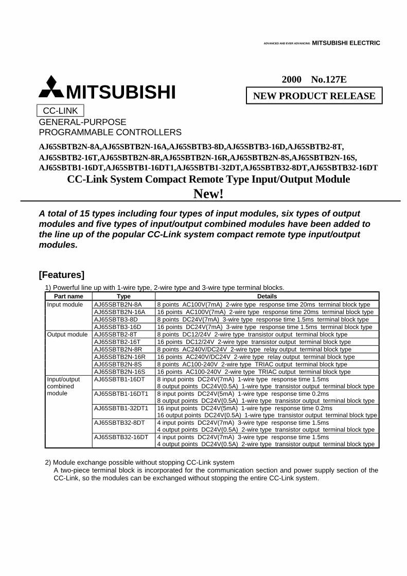
2000 No.127E NEW PRODUCT RELEASE
CC-LINK GENERAL-PURPOSE PROGRAMMABLE CONTROLLERS AJ65SBTB2N-8A,AJ65SBTB2N-16A,AJ65SBTB3-8D,AJ65SBTB3-16D,AJ65SBTB2-8T, AJ65SBTB2-16T,AJ65SBTB2N-8R,AJ65SBTB2N-16R,AJ65SBTB2N-8S,AJ65SBTB2N-16S, AJ65SBTB1-16DT,AJ65SBTB1-16DT1,AJ65SBTB1-32DT,AJ65SBTB32-8DT,AJ65SBTB32-16DT
CC-Link System Compact Remote Type Input/Output Module New!
A total of 15 types including four types of input modules, six types of output modules and five types of input/output combined modules have been added to the line up of the popular CC-Link system compact remote type input/output modules.
[Features]
1) Powerful line up with 1-wire type, 2-wire type and 3-wire type terminal blocks. Part name Type Details
AJ65SBTB2N-8A 8 points AC100V(7mA) 2-wire type response time 20ms terminal block type AJ65SBTB2N-16A 16 points AC100V(7mA) 2-wire type response time 20ms terminal block type AJ65SBTB3-8D 8 points DC24V(7mA) 3-wire type response time 1.5ms terminal block type
Input module
AJ65SBTB3-16D 16 points DC24V(7mA) 3-wire type response time 1.5ms terminal block type AJ65SBTB2-8T 8 points DC12/24V 2-wire type transistor output terminal block type AJ65SBTB2-16T 16 points DC12/24V 2-wire type transistor output terminal block type AJ65SBTB2N-8R 8 points AC240V/DC24V 2-wire type relay output terminal block type AJ65SBTB2N-16R 16 points AC240V/DC24V 2-wire type relay output terminal block type AJ65SBTB2N-8S 8 points AC100-240V 2-wire type TRIAC output terminal block type
Output module
AJ65SBTB2N-16S 16 points AC100-240V 2-wire type TRIAC output terminal block type AJ65SBTB1-16DT 8 input points DC24V(7mA) 1-wire type response time 1.5ms
8 output points DC24V(0.5A) 1-wire type transistor output terminal block type AJ65SBTB1-16DT1 8 input points DC24V(5mA) 1-wire type response time 0.2ms
8 output points DC24V(0.5A) 1-wire type transistor output terminal block type AJ65SBTB1-32DT1 16 input points DC24V(5mA) 1-wire type response time 0.2ms
16 output points DC24V(0.5A) 1-wire type transistor output terminal block type AJ65SBTB32-8DT 4 input points DC24V(7mA) 3-wire type response time 1.5ms
4 output points DC24V(0.5A) 2-wire type transistor output terminal block type
Input/output combined module
AJ65SBTB32-16DT 4 input points DC24V(7mA) 3-wire type response time 1.5ms 4 output points DC24V(0.5A) 2-wire type transistor output terminal block type
2) Module exchange possible without stopping CC-Link system
A two-piece terminal block is incorporated for the communication section and power supply section of the CC-Link, so the modules can be exchanged without stopping the entire CC-Link system.
ADVANCED AND EVER ADVANCING MITSUBISHI ELECTRIC
MITSUBISHI
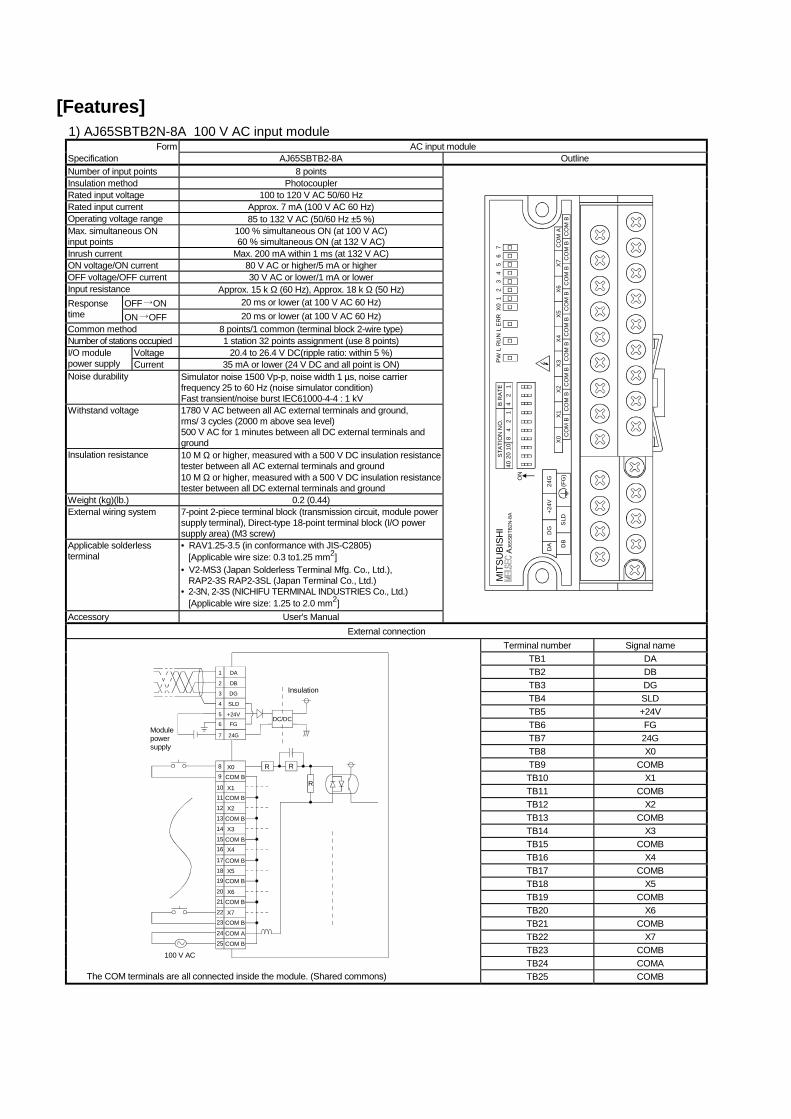
[Features] 1) AJ65SBTB2N-8A 100 V AC input module
Form AC input module Specification AJ65SBTB2-8A Outline Number of input points 8 points Insulation method Photocoupler Rated input voltage 100 to 120 V AC 50/60 Hz Rated input current Approx. 7 mA (100 V AC 60 Hz) Operating voltage range 85 to 132 V AC (50/60 Hz ±5 %) Max. simultaneous ON input points
100 % simultaneous ON (at 100 V AC) 60 % simultaneous ON (at 132 V AC)
Inrush current Max. 200 mA within 1 ms (at 132 V AC) ON voltage/ON current 80 V AC or higher/5 mA or higher OFF voltage/OFF current 30 V AC or lower/1 mA or lower Input resistance Approx. 15 k Ω (60 Hz), Approx. 18 k Ω (50 Hz)
OFF ON 20 ms or lower (at 100 V AC 60 Hz) Response time ON OFF 20 ms or lower (at 100 V AC 60 Hz) Common method 8 points/1 common (terminal block 2-wire type) Number of stations occupied 1 station 32 points assignment (use 8 points)
Voltage 20.4 to 26.4 V DC(ripple ratio: within 5 %) I/O module power supply Current 35 mA or lower (24 V DC and all point is ON) Noise durability Simulator noise 1500 Vp-p, noise width 1 µs, noise carrier
frequency 25 to 60 Hz (noise simulator condition) Fast transient/noise burst IEC61000-4-4 : 1 kV
Withstand voltage 1780 V AC between all AC external terminals and ground, rms/ 3 cycles (2000 m above sea level) 500 V AC for 1 minutes between all DC external terminals and ground
Insulation resistance 10 M Ω or higher, measured with a 500 V DC insulation resistance tester between all AC external terminals and ground 10 M Ω or higher, measured with a 500 V DC insulation resistance tester between all DC external terminals and ground
Weight (kg)(lb.) 0.2 (0.44) External wiring system 7-point 2-piece terminal block (transmission circuit, module power
supply terminal), Direct-type 18-point terminal block (I/O power supply area) (M3 screw)
Applicable solderless terminal
• RAV1.25-3.5 (in conformance with JIS-C2805) [Applicable wire size: 0.3 to1.25 mm2]
• V2-MS3 (Japan Solderless Terminal Mfg. Co., Ltd.), RAP2-3S RAP2-3SL (Japan Terminal Co., Ltd.)
• 2-3N, 2-3S (NICHIFU TERMINAL INDUSTRIES Co., Ltd.) [Applicable wire size: 1.25 to 2.0 mm2]
Accessory User's Manual
4020
108
42
14
21
B R
ATE
STAT
ION
NO
.M
ITSU
BISH
IPW
L R
UN
L ER
RX0
12
34
56
7
CO
M B
AJ65
SBTB
2N-8
A
DB
DA
SLD
DG
+24V
24G
(FG
)C
OM
BC
OM
BC
OM
BC
OM
BC
OM
BC
OM
BC
OM
BC
OM
BC
OM
AX7
X6X5
X4X3
X2X1
X0
ON
External connection Terminal number Signal name
TB1 DA TB2 DB TB3 DG TB4 SLD TB5 +24V TB6 FG TB7 24G TB8 X0 TB9 COMB TB10 X1 TB11 COMB TB12 X2 TB13 COMB TB14 X3 TB15 COMB TB16 X4 TB17 COMB TB18 X5 TB19 COMB TB20 X6 TB21 COMB TB22 X7 TB23 COMB TB24 COMA
98
1011
12
13
14
1615
17
1819
2021
X0COM B
X1COM B
X2
COM B
X3
COM BX4
COM B
X5COM B
X6COM B
X7COM B
COM A
COM B
2223
24
25
DA
DB
DG
SLD
+24V
FG
24G
2
1
3
4
5
6
7
R R
R
Modulepowersupply
Insulation
100 V AC
DC/DC
The COM terminals are all connected inside the module. (Shared commons) TB25 COMB
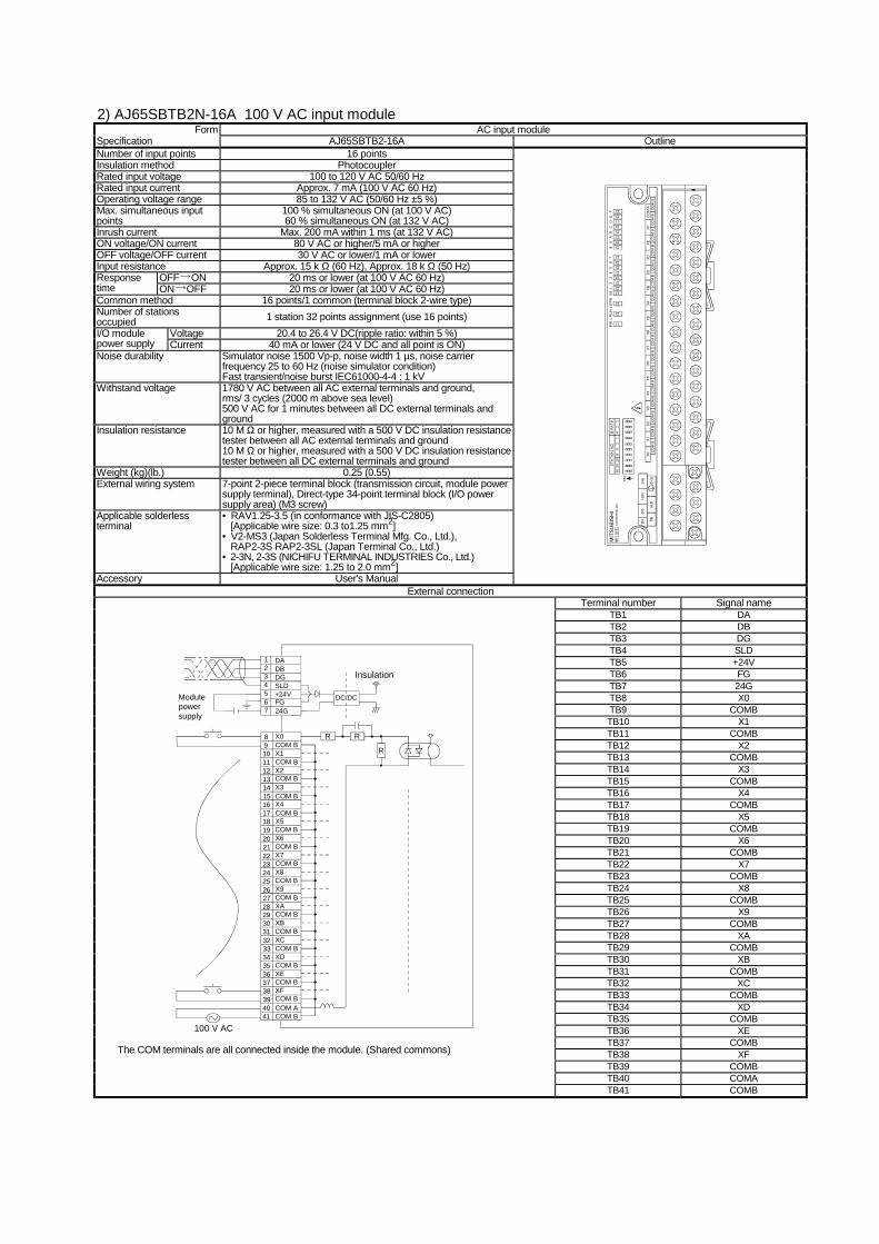
2) AJ65SBTB2N-16A 100 V AC input module Form AC input module
Specification AJ65SBTB2-16A Outline Number of input points 16 points Insulation method Photocoupler Rated input voltage 100 to 120 V AC 50/60 Hz Rated input current Approx. 7 mA (100 V AC 60 Hz) Operating voltage range 85 to 132 V AC (50/60 Hz ±5 %) Max. simultaneous input points
100 % simultaneous ON (at 100 V AC) 60 % simultaneous ON (at 132 V AC)
Inrush current Max. 200 mA within 1 ms (at 132 V AC) ON voltage/ON current 80 V AC or higher/5 mA or higher OFF voltage/OFF current 30 V AC or lower/1 mA or lower Input resistance Approx. 15 k Ω (60 Hz), Approx. 18 k Ω (50 Hz)
OFF ON 20 ms or lower (at 100 V AC 60 Hz) Response time ON OFF 20 ms or lower (at 100 V AC 60 Hz) Common method 16 points/1 common (terminal block 2-wire type) Number of stations occupied 1 station 32 points assignment (use 16 points)
Voltage 20.4 to 26.4 V DC(ripple ratio: within 5 %) I/O module power supply Current 40 mA or lower (24 V DC and all point is ON) Noise durability Simulator noise 1500 Vp-p, noise width 1 µs, noise carrier
frequency 25 to 60 Hz (noise simulator condition) Fast transient/noise burst IEC61000-4-4 : 1 kV
Withstand voltage 1780 V AC between all AC external terminals and ground, rms/ 3 cycles (2000 m above sea level) 500 V AC for 1 minutes between all DC external terminals and ground
Insulation resistance 10 M Ω or higher, measured with a 500 V DC insulation resistance tester between all AC external terminals and ground 10 M Ω or higher, measured with a 500 V DC insulation resistance tester between all DC external terminals and ground
Weight (kg)(lb.) 0.25 (0.55) External wiring system 7-point 2-piece terminal block (transmission circuit, module power
supply terminal), Direct-type 34-point terminal block (I/O power supply area) (M3 screw)
Applicable solderless terminal
• RAV1.25-3.5 (in conformance with JIS-C2805) [Applicable wire size: 0.3 to1.25 mm2]
• V2-MS3 (Japan Solderless Terminal Mfg. Co., Ltd.), RAP2-3S RAP2-3SL (Japan Terminal Co., Ltd.)
• 2-3N, 2-3S (NICHIFU TERMINAL INDUSTRIES Co., Ltd.) [Applicable wire size: 1.25 to 2.0 mm2]
Accessory User's Manual
MIT
SUBI
SHI
AJ65
SBTB
2N-1
6A40
2010
84
21
42
1B
RA
TEST
ATI
ON
NO
.
ON
DB
DA
SLD
DG
+24V
24G
(FG
)C
OM
BC
OM
BC
OM
BC
OM
BC
OM
BC
OM
BC
OM
BC
OM
BC
OM
AXF
XEXD
XCXB
XAX9
CO
M B
CO
M B
CO
M B
CO
M B
CO
M B
CO
M B
CO
M B
CO
M B
CO
M B
X8X7
X6X5
X4X3
X2X1
X0
PWL
RU
NL
ER
RX0
12
34
56
78
9A
BC
DE
F
External connection Terminal number Signal name
TB1 DA TB2 DB TB3 DG TB4 SLD TB5 +24V TB6 FG TB7 24G TB8 X0 TB9 COMB TB10 X1 TB11 COMB TB12 X2 TB13 COMB TB14 X3 TB15 COMB TB16 X4 TB17 COMB TB18 X5 TB19 COMB TB20 X6 TB21 COMB TB22 X7 TB23 COMB TB24 X8 TB25 COMB TB26 X9 TB27 COMB TB28 XA TB29 COMB TB30 XB TB31 COMB TB32 XC TB33 COMB TB34 XD TB35 COMB TB36 XE TB37 COMB TB38 XF TB39 COMB TB40 COMA
DADBDGSLD+24VFG24G
21
34567
98 X0
COM BX1COM BX2COM BX3COM BX4COM BX5COM BX6COM BX7COM BX8COM BX9COM BXACOM BXBCOM BXCCOM BXDCOM BXECOM BXFCOM BCOM ACOM B
1011121314
1615
17181920
2221
23242526
2827
29303132
3433
35363738
4039
41
100 V AC
Insulation
R R
R
DC/DCModulepowersupply
The COM terminals are all connected inside the module. (Shared commons)
TB41 COMB
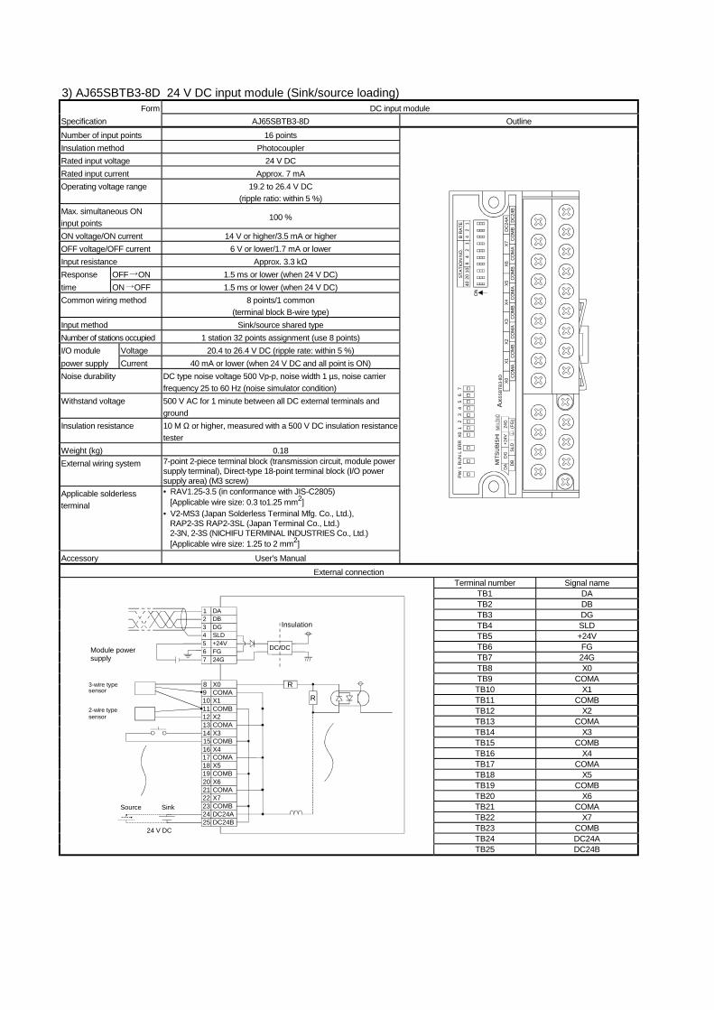
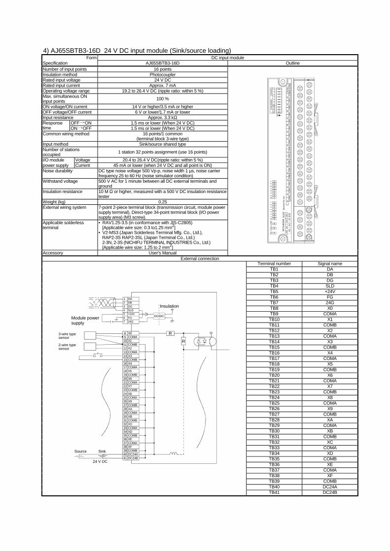
3) AJ65SBTB3-8D 24 V DC input module (Sink/source loading) Form DC input module
Specification AJ65SBTB3-8D Outline Number of input points 16 points Insulation method Photocoupler Rated input voltage 24 V DC Rated input current Approx. 7 mA Operating voltage range 19.2 to 26.4 V DC
(ripple ratio: within 5 %) Max. simultaneous ON input points
100 %
ON voltage/ON current 14 V or higher/3.5 mA or higher OFF voltage/OFF current 6 V or lower/1.7 mA or lower Input resistance Approx. 3.3 kΩ Response OFF ON 1.5 ms or lower (when 24 V DC) time ON OFF 1.5 ms or lower (when 24 V DC) Common wiring method 8 points/1 common
(terminal block B-wire type) Input method Sink/source shared type Number of stations occupied 1 station 32 points assignment (use 8 points) I/O module Voltage 20.4 to 26.4 V DC (ripple rate: within 5 %) power supply Current 40 mA or lower (when 24 V DC and all point is ON) Noise durability DC type noise voltage 500 Vp-p, noise width 1 µs, noise carrier
frequency 25 to 60 Hz (noise simulator condition) Withstand voltage 500 V AC for 1 minute between all DC external terminals and
ground Insulation resistance 10 M Ω or higher, measured with a 500 V DC insulation resistance
tester Weight (kg) 0.18 External wiring system 7-point 2-piece terminal block (transmission circuit, module power
supply terminal), Direct-type 18-point terminal block (I/O power supply area) (M3 screw)
Applicable solderless terminal
• RAV1.25-3.5 (in conformance with JIS-C2805) [Applicable wire size: 0.3 to1.25 mm2]
• V2-MS3 (Japan Solderless Terminal Mfg. Co., Ltd.), RAP2-3S RAP2-3SL (Japan Terminal Co., Ltd.) 2-3N, 2-3S (NICHIFU TERMINAL INDUSTRIES Co., Ltd.) [Applicable wire size: 1.25 to 2 mm2]
Accessory User's Manual
CO
MB
CO
MA
CO
MB
CO
MA
CO
MA
CO
MB
CO
MA
CO
MB
DC
24B
DC
24A
X7X6
X5X4
X3X2
X1X0
4020
108
42
14
21
B R
ATE
STA
TIO
N N
O.
ON
PWL
RU
NL
ERR
X01
23
45
67
AJ65
SBTB
3-8D
DA
DG
+24V
24G
DB
SLD
(FG
)
MIT
SUBI
SHI
External connection Terminal number Signal name
TB1 DA TB2 DB TB3 DG TB4 SLD TB5 +24V TB6 FG TB7 24G TB8 X0 TB9 COMA TB10 X1 TB11 COMB TB12 X2 TB13 COMA TB14 X3 TB15 COMB TB16 X4 TB17 COMA TB18 X5 TB19 COMB TB20 X6 TB21 COMA TB22 X7 TB23 COMB TB24 DC24A
Module powersupply
DC/DC
DADBDGSLD+24VFG24G
21
34567
Insulation
X0COMAX1COMBX2COMAX3
98
1011121314
COMBX4COMAX5COMBX6COMA
1615
1718192021
X7COMBDC24ADC24B
22232425
24 V DC
R
R
3-wire type sensor
2-wire typesensor
Source Sink
TB25 DC24B
4) AJ65SBTB3-16D 24 V DC input module (Sink/source loading) Form DC input module
Specification AJ65SBTB3-16D Outline Number of input points 16 points Insulation method Photocoupler Rated input voltage 24 V DC Rated input current Approx. 7 mA Operating voltage range 19.2 to 26.4 V DC (ripple ratio: within 5 %) Max. simultaneous ON input points 100 %
ON voltage/ON current 14 V or higher/3.5 mA or higher OFF voltage/OFF current 6 V or lower/1.7 mA or lower Input resistance Approx. 3.3 kΩ
OFF ON 1.5 ms or lower (When 24 V DC) Response time ON OFF 1.5 ms or lower (When 24 V DC) Common wiring method 16 points/1 common
(terminal block 3-wire type) Input method Sink/source shared type Number of stations occupied 1 station 32 points assignment (use 16 points)
I/O module Voltage 20.4 to 26.4 V DC(ripple ratio: within 5 %) power supply Current 45 mA or lower (when 24 V DC and all point is ON) Noise durability DC type noise voltage 500 Vp-p, noise width 1 µs, noise carrier
frequency 25 to 60 Hz (noise simulator condition) Withstand voltage 500 V AC for 1 minute between all DC external terminals and
ground Insulation resistance 10 M Ω or higher, measured with a 500 V DC insulation resistance
tester Weight (kg) 0.25 External wiring system 7-point 2-piece terminal block (transmission circuit, module power
supply terminal), Direct-type 34-point terminal block (I/O power supply area) (M3 screw).
Applicable solderless terminal
• RAV1.25-3.5 (in conformance with JIS-C2805) [Applicable wire size: 0.3 to1.25 mm2]
• V2-MS3 (Japan Solderless Terminal Mfg. Co., Ltd.), RAP2-3S RAP2-3SL (Japan Terminal Co., Ltd.) 2-3N, 2-3S (NICHIFU TERMINAL INDUSTRIES Co., Ltd.) [Applicable wire size: 1.25 to 2 mm2]
Accessory User's Manual
4020
108
42
14
21
B R
ATE
STAT
ION
NO
.
ON
CO
MA
CO
MB
CO
MA
CO
MB
CO
MB
CO
MA
CO
MB
DC
24B
DC
24A
XFXE
XDXC
XBYA
Y9C
OM
BC
OM
AC
OM
BC
OM
AC
OM
AC
OM
BC
OM
AC
OM
BC
OM
AX8
X7X6
X5X4
X3X2
X1X0
PWL
RU
NL
ERR
X01
23
45
67
X89
AB
CD
EF
AJ6
5SB
TB3-
16D
DA
DG
+24V
24G
DB
SLD
(FG
)
MIT
SUB
ISH
I
External connection Terminal number Signal name
TB1 DA TB2 DB TB3 DG TB4 SLD TB5 +24V TB6 FG TB7 24G TB8 X0 TB9 COMA TB10 X1 TB11 COMB TB12 X2 TB13 COMA TB14 X3 TB15 COMB TB16 X4 TB17 COMA TB18 X5 TB19 COMB TB20 X6 TB21 COMA TB22 X7 TB23 COMB TB24 X8 TB25 COMA TB26 X9 TB27 COMB TB28 XA TB29 COMA TB30 XB TB31 COMB TB32 XC TB33 COMA TB34 XD TB35 COMB TB36 XE TB37 COMA TB38 XF TB39 COMB TB40 DC24A
Module powersupply
DC/DC
DADBDGSLD+24VFG24G
21
34567
Insulation
X0COMAX1COMBX2COMAX3
1011121314
COMBX4COMAX5COMB
1615
171819
X620COMAX7COMBX8COMA
2221
232425
X926COMBXACOMAXBCOMB
2827
293031
XC32COMAXDCOMBXECOMA
3433
353637
XF38COMBDC24ADC24B
4039
4124 V DC
89
R
R2-wire typesensor
3-wire typesensor
Source Sink
TB41 DC24B
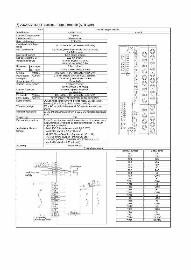
5) AJ65SBTB2-8T transistor output module (Sink type) Form Transistor output module
Specification AJ65SBTB2-8T Outline Number of output points 8 points Insulation method Photocoupler Rated load voltage 12/24 V DC Operating load voltage range 10.2 to 26.4 V DC (ripple ratio: within 5 %)
Max. load current 0.5 A/point (when all point 5 are ON: 0.3 A/point) 2.4 A/1 common
Max. inrush current 1.0 A 10 ms or lower Leakage current at OFF 0.25 mA or lower Voltage drop at ON 0.3 V or lower (TYP) 0.5 A
0.6 V or lower (MAX) 0.5 A Response OFF ON 0.5 ms or lower time ON OFF 1.5 ms or lower (resistive load) External Voltage 10.2 to 26.4 V DC (ripple ratio: within 5 %) Power supply for output
Current 17.8 mA or lower (TYP.24 V DC/1 common) Not including external load current
Surge suppression Zener diode Common wiring method 8 points/1 common
(terminal block 2-wire type) Number of stations occupied
1 station 32 points assignment (use 8 points)
I/O module Voltage 20.4 to 26.4 V DC (ripple ratio: within 5 %) power supply Current 45 mA or lower (when 24 V DC and all point is ON) Noise durability DC type noise voltage 500 Vp-p, noise width 1 µs, noise carrier
frequency 25 to 60 Hz (noise simulator condition) Withstand voltage 500 V AC for 1 minute between all DC external terminals and
ground Insulation resistance 10 MΩ or higher, measured with a 500 V DC insulation resistance
tester Weight (kg) 0.18 External wiring system 7-point 2-piece terminal block (transmission circuit, module power
supply terminal), Direct-type 18-point terminal block (I/O power supply area) (M3 screw)
Applicable solderless terminal
• RAV1.25-3.5 (in conformance with JIS C 2805) [Applicable wire size: 0.3 to1.25 mm2]
• V2-MS3 (Japan Solderless Terminal Mfg. Co., Ltd.), RAP2-3S RAP2-3 (Japan Terminal Co., Ltd.)
• 2-3N, 2-3S (NICHIFU TERMINAL INDUSTRIES Co., Ltd.) [Applicable wire size: 1.25 to 2 mm2]
Accessory User’s Manual
CO
MC
OM
CO
MC
OM
CO
MC
OM
CO
MC
OM
DC
24G
DC
24V
Y7Y6
Y5Y4
Y3Y2
Y1Y0
4020
108
42
14
21
B R
ATE
STAT
ION
NO
.
ON
PWL
RU
NL
ER
RY0
12
34
56
7
AJ6
5SBT
B2-8
TD
AD
G+2
4V24
GD
BSL
D(F
G)
MIT
SUBI
SHI
External connection Terminal number Signal name
TB1 DA TB2 DB TB3 DG TB4 SLD TB5 +24V TB6 FG TB7 24G TB8 Y0 TB9 COM TB10 Y1 TB11 COM TB12 Y2 TB13 COM TB14 Y3 TB15 COM TB16 Y4 TB17 COM TB18 Y5 TB19 COM TB20 Y6 TB21 COM TB22 Y7 TB23 COM TB24 DC24V TB25 DC24G
Module powersupply
DC/DC
DADBDGSLD+24VFG24G
21
34567
Insulation
Y0COMY1COMY2COMY3
98
1011121314
COMY4COMY5COMY6COM
1615
1718192021
Y7COMDC24VDC24G
22232425
L
Constant voltage circuit
I/O power supply (external supply power)
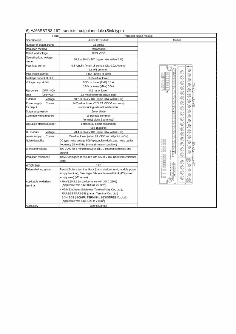
6) AJ65SBTB2-16T transistor output module (Sink type) Form Transistor output module
Specification AJ65SBTB2-16T Outline Number of output points 16 points Insulation method Photocoupler Rated load voltage 12/24 V DC Operating load voltage range
10.2 to 26.4 V DC (ripple ratio: within 5 %)
Max. load current 0.5 A/point (when all point is ON: 0.22 A/point) 3.6 A/1 common
Max. inrush current 1.0 A 10 ms or lower Leakage current at OFF 0.25 mA or lower Voltage drop at ON 0.3 V or lower (TYP) 0.5 A
0.6 V or lower (MAX) 0.5 A Response OFF ON 0.5 ms or lower time ON OFF 1.5 ms or lower (resistive load) External Voltage 10.2 to 26.4 V DC (ripple ratio: within 5 %) Power supply for output
Current 24.2 mA or lower (TYP.24 V DC/1 common) Not including external load current
Surge suppression Zener diode Common wiring method 16 points/1 common
(terminal block 2-wire type) Occupied station number 1 station 32 points assignment
(use 16 points) I/O module Voltage 20.4 to 26.4 V DC (ripple ratio: within 5 %) power supply Current 55 mA or lower (when 24 V DC and all point is ON) Noise durability DC type noise voltage 500 Vp-p, noise width 1 µs, noise carrier
frequency 25 to 60 Hz (noise simulator condition) Withstand voltage 500 V AC for 1 minute between all DC external terminals and
ground Insulation resistance 10 MΩ or higher, measured with a 500 V DC insulation resistance
tester Weight (kg) 0.25 External wiring system 7-point 2-piece terminal block (transmission circuit, module power
supply terminal), Direct-type 34-point terminal block (I/O power supply area) (M3 screw)
Applicable solderless terminal
• RAV1.25-3.5 (in conformance with JIS C 2805) [Applicable wire size: 0.3 to1.25 mm2]
• V2-MS3 (Japan Solderless Terminal Mfg. Co., Ltd.), RAP2-3S RAP2-3SL (Japan Terminal Co., Ltd.) 2-3N, 2-3S (NICHIFU TERMINAL INDUSTRIES Co., Ltd.) [Applicable wire size: 1.25 to 2 mm2]
Accessory User’s Manual
4020
108
42
14
21
B R
ATE
STAT
ION
NO
.
ON CO
MCO
MCO
MCO
MCO
MCO
MCO
MDC
24G
DC24
VYF
YEYD
YCYB
YAY9
COM
COM
COM
COM
COM
COM
COM
COM
COM
Y8Y7
Y6Y5
Y4Y3
Y2Y1
Y0
PWL
RUN
L ER
RY0
12
34
56
7Y8
9A
BC
DE
F
AJ6
5SBT
B2-1
6TDA
DG+2
4V24
GDB
SLD
(FG
)
MIT
SUBI
SH
I
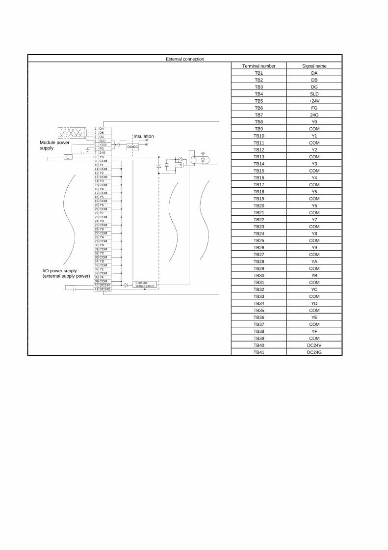
External connection
Terminal number Signal name TB1 DA TB2 DB TB3 DG TB4 SLD TB5 +24V TB6 FG TB7 24G TB8 Y0 TB9 COM TB10 Y1 TB11 COM TB12 Y2 TB13 COM TB14 Y3 TB15 COM TB16 Y4 TB17 COM TB18 Y5 TB19 COM TB20 Y6 TB21 COM TB22 Y7 TB23 COM TB24 Y8 TB25 COM TB26 Y9 TB27 COM TB28 YA TB29 COM TB30 YB TB31 COM TB32 YC TB33 COM TB34 YD TB35 COM TB36 YE TB37 COM TB38 YF TB39 COM TB40 DC24V
Module powersupply DC/DC
DADBDGSLD+24VFG24G
21
34567
Insulation
Y0COMY1COMY2COMY3
1011121314
COMY4COMY5COM
1615
171819
Y620COMY7COMY8COM
2221
232425
Y926COMYACOMYBCOM
2827
293031
YC32COMYDCOMYECOM
3433
353637
YF38COMDC24VDC24G
4039
41
89
L
Constant voltage circuit
I/O power supply (external supply power)
TB41 DC24G
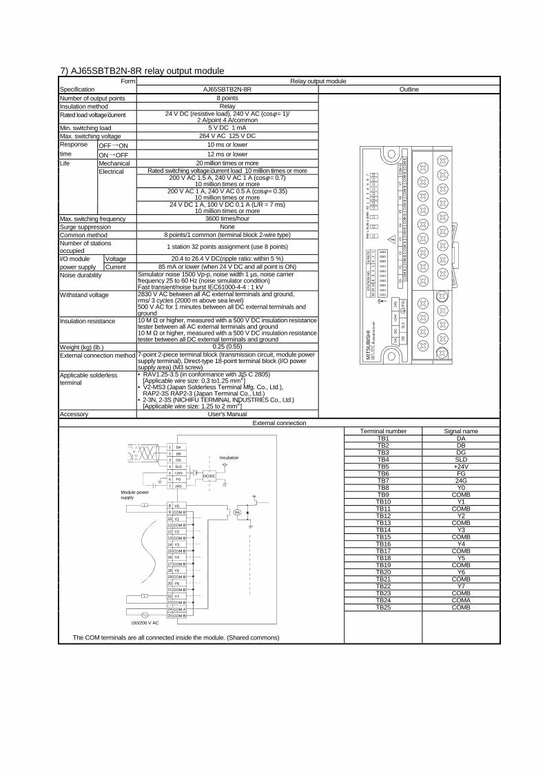
7) AJ65SBTB2N-8R relay output module Form Relay output module
Specification AJ65SBTB2N-8R Outline Number of output points 8 points Insulation method Relay Rated load voltage⋅current 24 V DC (resistive load), 240 V AC (cosφ = 1)/
2 A/point 4 A/common Min. switching load 5 V DC 1 mA Max. switching voltage 264 V AC 125 V DC Response OFF ON 10 ms or lower time ON OFF 12 ms or lower
Mechanical 20 million times or more Rated switching voltage⋅current load 10 million times or more
200 V AC 1.5 A, 240 V AC 1 A (cosφ = 0.7) 10 million times or more
200 V AC 1 A, 240 V AC 0.5 A (cosφ = 0.35) 10 million times or more
Life Electrical
24 V DC 1 A, 100 V DC 0.1 A (L/R = 7 ms) 10 million times or more
Max. switching frequency 3600 times/hour Surge suppression None Common method 8 points/1 common (terminal block 2-wire type) Number of stations occupied 1 station 32 points assignment (use 8 points)
I/O module Voltage 20.4 to 26.4 V DC(ripple ratio: within 5 %) power supply Current 85 mA or lower (when 24 V DC and all point is ON) Noise durability Simulator noise 1500 Vp-p, noise width 1 µs, noise carrier
frequency 25 to 60 Hz (noise simulator condition) Fast transient/noise burst IEC61000-4-4 : 1 kV
Withstand voltage 2830 V AC between all AC external terminals and ground, rms/ 3 cycles (2000 m above sea level) 500 V AC for 1 minutes between all DC external terminals and ground
Insulation resistance 10 M Ω or higher, measured with a 500 V DC insulation resistance tester between all AC external terminals and ground 10 M Ω or higher, measured with a 500 V DC insulation resistance tester between all DC external terminals and ground
Weight (kg) (lb.) 0.25 (0.55) External connection method 7-point 2-piece terminal block (transmission circuit, module power
supply terminal), Direct-type 18-point terminal block (I/O power supply area) (M3 screw)
Applicable solderless terminal
• RAV1.25-3.5 (in conformance with JIS C 2805) [Applicable wire size: 0.3 to1.25 mm2]
• V2-MS3 (Japan Solderless Terminal Mfg. Co., Ltd.), RAP2-3S RAP2-3 (Japan Terminal Co., Ltd.)
• 2-3N, 2-3S (NICHIFU TERMINAL INDUSTRIES Co., Ltd.) [Applicable wire size: 1.25 to 2 mm2]
Accessory User's Manual
4020
108
42
14
21
B R
ATE
STAT
ION
NO
.M
ITSU
BISH
IPW
L R
UN
L ER
RY0
12
34
56
7
CO
M B
AJ6
5SBT
B2N
-8R
DB
DA
SLD
DG
+24V
24G
(FG
)C
OM
BC
OM
BC
OM
BC
OM
BC
OM
BC
OM
BC
OM
BC
OM
BC
OM
AY7
Y6Y5
Y4Y3
Y2Y1
Y0
ON
External connection Terminal number Signal name
TB1 DA TB2 DB TB3 DG TB4 SLD TB5 +24V TB6 FG TB7 24G TB8 Y0 TB9 COMB TB10 Y1 TB11 COMB TB12 Y2 TB13 COMB TB14 Y3 TB15 COMB TB16 Y4 TB17 COMB TB18 Y5 TB19 COMB TB20 Y6 TB21 COMB TB22 Y7 TB23 COMB TB24 COMA TB25 COMB
L
L
98
1011121314
1615
171819
2021
Y0COM B
Y1COM BY2
COM BY3
COM BY4
COM BY5
COM B
Y6COM B
Y7COM B
COM ACOM B
2223
24
25
DA
DB
DG
SLD
+24V
FG
24G
2
1
3
4
5
6
7
Module powersupply
Insulation
DC/DC
100/200 V AC
RA
The COM terminals are all connected inside the module. (Shared commons)
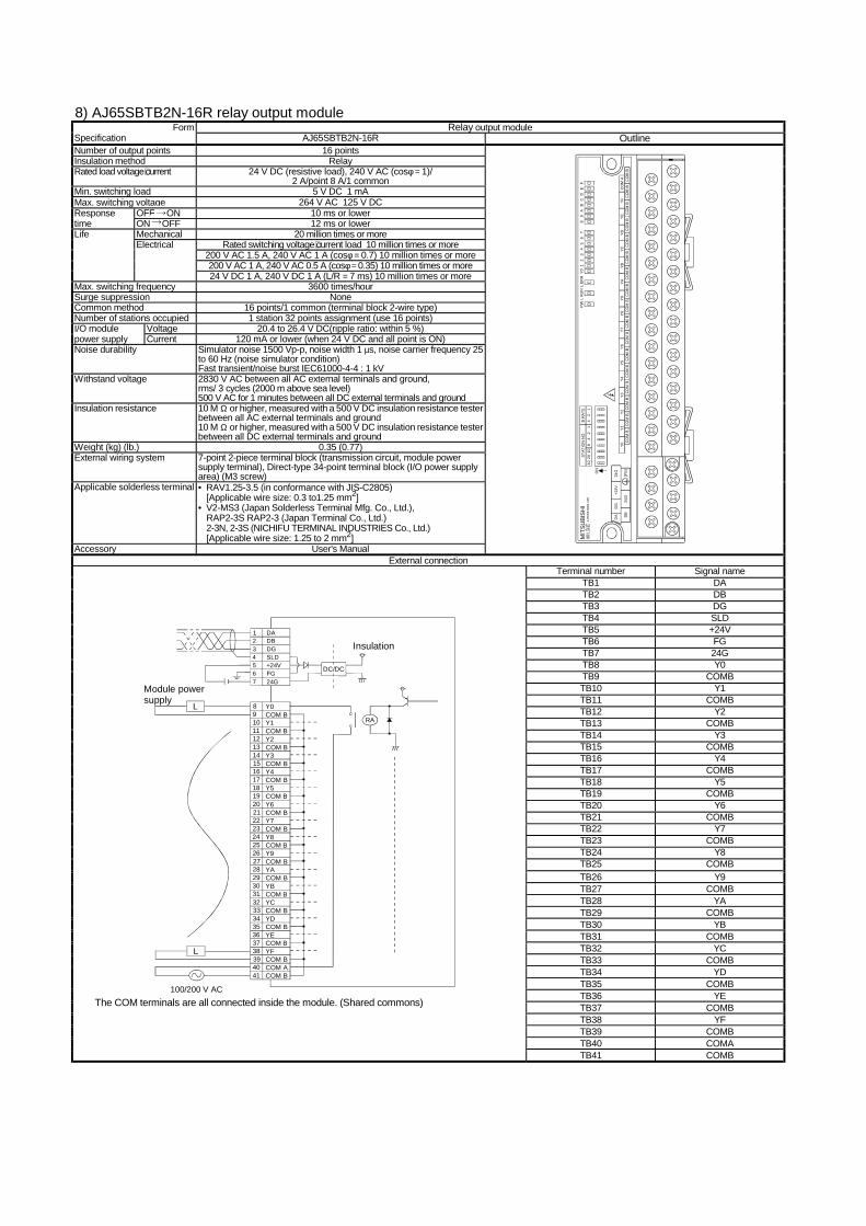
8) AJ65SBTB2N-16R relay output module Form Relay output module
Specification AJ65SBTB2N-16R Outline Number of output points 16 points Insulation method Relay Rated load voltage⋅current 24 V DC (resistive load), 240 V AC (cosφ = 1)/
2 A/point 8 A/1 common Min. switching load 5 V DC 1 mA Max. switching voltage 264 V AC 125 V DC Response OFF ON 10 ms or lower time ON OFF 12 ms or lower
Mechanical 20 million times or more Rated switching voltage⋅current load 10 million times or more
200 V AC 1.5 A, 240 V AC 1 A (cosφ = 0.7) 10 million times or more 200 V AC 1 A, 240 V AC 0.5 A (cosφ = 0.35) 10 million times or more
Life Electrical
24 V DC 1 A, 240 V DC 1 A (L/R = 7 ms) 10 million times or more Max. switching frequency 3600 times/hour Surge suppression None Common method 16 points/1 common (terminal block 2-wire type) Number of stations occupied 1 station 32 points assignment (use 16 points) I/O module Voltage 20.4 to 26.4 V DC(ripple ratio: within 5 %) power supply Current 120 mA or lower (when 24 V DC and all point is ON) Noise durability Simulator noise 1500 Vp-p, noise width 1 µs, noise carrier frequency 25
to 60 Hz (noise simulator condition) Fast transient/noise burst IEC61000-4-4 : 1 kV
Withstand voltage 2830 V AC between all AC external terminals and ground, rms/ 3 cycles (2000 m above sea level) 500 V AC for 1 minutes between all DC external terminals and ground
Insulation resistance 10 M Ω or higher, measured with a 500 V DC insulation resistance tester between all AC external terminals and ground 10 M Ω or higher, measured with a 500 V DC insulation resistance tester between all DC external terminals and ground
Weight (kg) (lb.) 0.35 (0.77) External wiring system 7-point 2-piece terminal block (transmission circuit, module power
supply terminal), Direct-type 34-point terminal block (I/O power supply area) (M3 screw)
Applicable solderless terminal • RAV1.25-3.5 (in conformance with JIS-C2805) [Applicable wire size: 0.3 to1.25 mm2]
• V2-MS3 (Japan Solderless Terminal Mfg. Co., Ltd.), RAP2-3S RAP2-3 (Japan Terminal Co., Ltd.) 2-3N, 2-3S (NICHIFU TERMINAL INDUSTRIES Co., Ltd.) [Applicable wire size: 1.25 to 2 mm2]
Accessory User's Manual
MIT
SUBI
SHI
AJ6
5SB
TB2
N-1
6R40
2010
84
21
42
1B
RA
TES
TATI
ON
NO
.
ON
DB
DA
SLD
DG
+24V
24G
(FG
)C
OM
BC
OM
BC
OM
BC
OM
BC
OM
BC
OM
BC
OM
BC
OM
BC
OM
AY
FY
EY
DY
CY
BY
AY
9C
OM
BC
OM
BC
OM
BC
OM
BC
OM
BC
OM
BC
OM
BC
OM
BC
OM
BY
8Y
7Y
6Y
5Y
4Y
3Y
2Y
1Y
0
PW
L R
UN
L E
RR
Y0
12
34
56
78
9A
BC
DE
F
External connection Terminal number Signal name
TB1 DA TB2 DB TB3 DG TB4 SLD TB5 +24V TB6 FG TB7 24G TB8 Y0 TB9 COMB TB10 Y1 TB11 COMB TB12 Y2 TB13 COMB TB14 Y3 TB15 COMB TB16 Y4 TB17 COMB TB18 Y5 TB19 COMB TB20 Y6 TB21 COMB TB22 Y7 TB23 COMB TB24 Y8 TB25 COMB TB26 Y9 TB27 COMB TB28 YA TB29 COMB TB30 YB TB31 COMB TB32 YC TB33 COMB TB34 YD TB35 COMB TB36 YE TB37 COMB TB38 YF TB39 COMB TB40 COMA
Module powersupply
DADBDGSLD+24VFG24G
21
34567
Insulation
COM B
Y0COM BY1COM BY2
Y3COM BY4COM BY5COM BY6COM BY7COM BY8COM BY9COM BYACOM BYBCOM BYCCOM BYDCOM BYECOM BYFCOM BCOM ACOM B
98
1011121314
1615
17181920
2221
23242526
2827
29303132
3433
35363738
4039
41
RA
L
100/200 V AC
L
DC/DC
The COM terminals are all connected inside the module. (Shared commons)
TB41 COMB
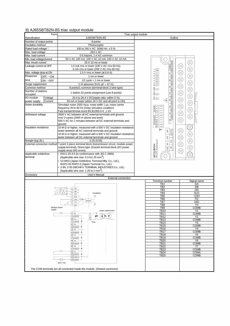
9) AJ65SBTB2N-8S triac output module Form Triac output module
Specification AJ65SBTB2N-8S Outline Number of output points 8 points Insulation method Photocoupler Rated load voltage⋅ 100 to 240 V AC 50/60 Hz ± 5 % Max. load voltage 264 V AC Max. load current 0.6 A/point, 2.4 A/1 common Min. load voltage⋅current 50 V AC 100 mA, 100 V AC 10 mA, 240 V AC 10 mA Max. inrush current 25 A 10 ms or lower Leakage current at OFF 1.5 mA rms or lower (100 V AC rms 60 Hz),
3 mA rms or lower (200 V AC rms 60 Hz) Max. voltage drop at ON 1.5 V rms or lower (at 0.6 A) Response OFF ON 1 ms or lower time ON OFF 1/2 cycle + 1 ms or lower Surge suppression C·R absorver (0.01 µF + 47 Ω) Common method 8 points/1 common (terminal block 2-wire type) Number of stations occupied 1 station 32 points assignment (use 8 points)
I/O module Voltage 20.4 to 26.4 V DC(ripple ratio: within 5 %) power supply Current 55 mA or lower (when 24 V DC and all point is ON) Noise durability Simulator noise 1500 Vp-p, noise width 1 µs, noise carrier
frequency 25 to 60 Hz (noise simulator condition) Fast transient/noise burst IEC61000-4-4 : 1 kV
Withstand voltage 2830 V AC between all AC external terminals and ground, rms/ 3 cycles (2000 m above sea level) 500 V AC for 1 minutes between all DC external terminals and ground
Insulation resistance 10 M Ω or higher, measured with a 500 V DC insulation resistance tester between all AC external terminals and ground 10 M Ω or higher, measured with a 500 V DC insulation resistance tester between all DC external terminals and ground
Weight (kg) (lb.) 0.25 (0.55) External connection method 7-point 2-piece terminal block (transmission circuit, module power
supply terminal), Direct-type 18-point terminal block (I/O power supply area) (M3 screw)
Applicable solderless terminal
• RAV1.25-3.5 (in conformance with JIS C 2805) [Applicable wire size: 0.3 to1.25 mm2]
• V2-MS3 (Japan Solderless Terminal Mfg. Co., Ltd.), RAP2-3S RAP2-3 (Japan Terminal Co., Ltd.)
• 2-3N, 2-3S (NICHIFU TERMINAL INDUSTRIES Co., Ltd.) [Applicable wire size: 1.25 to 2 mm2]
Accessory User's Manual
4020
108
42
14
21
B R
ATE
STAT
ION
NO
.M
ITSU
BISH
IPW
L R
UN
L ER
RY0
12
34
56
7
CO
M B
AJ65
SBTB
2N-8
S
DB
DA
SLD
DG
+24V
24G
(FG
)C
OM
BC
OM
BC
OM
BC
OM
BC
OM
BC
OM
BC
OM
BC
OM
BC
OM
AY7
Y6Y5
Y4Y3
Y2Y1
Y0
ON
External connection Terminal number Signal name
TB1 DA TB2 DB TB3 DG TB4 SLD TB5 +24V TB6 FG TB7 24G TB8 Y0 TB9 COMB TB10 Y1 TB11 COMB TB12 Y2 TB13 COMB TB14 Y3 TB15 COMB TB16 Y4 TB17 COMB TB18 Y5 TB19 COMB TB20 Y6 TB21 COMB TB22 Y7 TB23 COMB TB24 COMA TB25 COMB
L
L
98
10111213
14
1615
171819
2021
Y0COM B
Y1COM BY2
COM BY3
COM BY4
COM BY5
COM B
Y6COM B
Y7COM B
COM ACOM B
2223
2425
DA
DB
DG
SLD
+24V
FG
24G
2
1
3
4
5
6
7Module powersupply
Insulation
100 V AC
DC/DC
R
Triac
surge suppression
The COM terminals are all connected inside the module. (Shared commons)
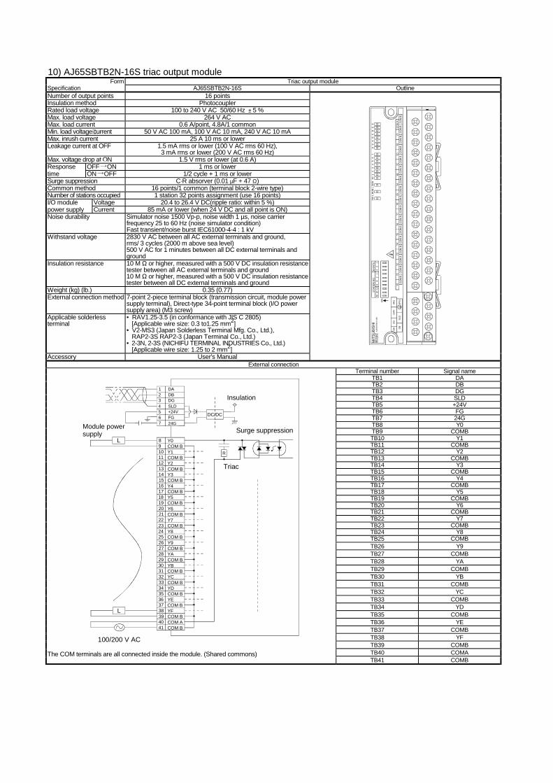
10) AJ65SBTB2N-16S triac output module Form Triac output module
Specification AJ65SBTB2N-16S Outline Number of output points 16 points Insulation method Photocoupler Rated load voltage 100 to 240 V AC 50/60 Hz ± 5 % Max. load voltage 264 V AC Max. load current 0.6 A/point, 4.8A/1 common Min. load voltage⋅current 50 V AC 100 mA, 100 V AC 10 mA, 240 V AC 10 mA Max. inrush current 25 A 10 ms or lower Leakage current at OFF 1.5 mA rms or lower (100 V AC rms 60 Hz),
3 mA rms or lower (200 V AC rms 60 Hz) Max. voltage drop at ON 1.5 V rms or lower (at 0.6 A) Response OFF ON 1 ms or lower time ON OFF 1/2 cycle + 1 ms or lower Surge suppression C·R absorver (0.01 µF + 47 Ω) Common method 16 points/1 common (terminal block 2-wire type) Number of stations occupied 1 station 32 points assignment (use 16 points) I/O module Voltage 20.4 to 26.4 V DC(ripple ratio: within 5 %) power supply Current 85 mA or lower (when 24 V DC and all point is ON) Noise durability Simulator noise 1500 Vp-p, noise width 1 µs, noise carrier
frequency 25 to 60 Hz (noise simulator condition) Fast transient/noise burst IEC61000-4-4 : 1 kV
Withstand voltage 2830 V AC between all AC external terminals and ground, rms/ 3 cycles (2000 m above sea level) 500 V AC for 1 minutes between all DC external terminals and ground
Insulation resistance 10 M Ω or higher, measured with a 500 V DC insulation resistance tester between all AC external terminals and ground 10 M Ω or higher, measured with a 500 V DC insulation resistance tester between all DC external terminals and ground
Weight (kg) (lb.) 0.35 (0.77) External connection method 7-point 2-piece terminal block (transmission circuit, module power
supply terminal), Direct-type 34-point terminal block (I/O power supply area) (M3 screw)
Applicable solderless terminal
• RAV1.25-3.5 (in conformance with JIS C 2805) [Applicable wire size: 0.3 to1.25 mm2]
• V2-MS3 (Japan Solderless Terminal Mfg. Co., Ltd.), RAP2-3S RAP2-3 (Japan Terminal Co., Ltd.)
• 2-3N, 2-3S (NICHIFU TERMINAL INDUSTRIES Co., Ltd.) [Applicable wire size: 1.25 to 2 mm2]
Accessory User's Manual
MIT
SU
BIS
HI
AJ6
5SBT
B2N
-16S
4020
108
42
14
21
B R
ATE
STAT
ION
NO
.
ON
DB
DA
SLD
DG
+24V
24G
(FG
)C
OM
BC
OM
BC
OM
BC
OM
BC
OM
BC
OM
BC
OM
BC
OM
BC
OM
AYF
YEYD
YCYB
YAY9
CO
M B
CO
M B
CO
M B
CO
M B
CO
M B
CO
M B
CO
M B
CO
M B
CO
M B
Y8Y7
Y6Y5
Y4Y3
Y2Y1
Y0
PWL
RU
NL
ERR
Y01
23
45
67
89
AB
CD
EF
External connection Terminal number Signal name
TB1 DA TB2 DB TB3 DG TB4 SLD TB5 +24V TB6 FG TB7 24G TB8 Y0 TB9 COMB TB10 Y1 TB11 COMB TB12 Y2 TB13 COMB TB14 Y3 TB15 COMB TB16 Y4 TB17 COMB TB18 Y5 TB19 COMB TB20 Y6 TB21 COMB TB22 Y7 TB23 COMB TB24 Y8 TB25 COMB TB26 Y9 TB27 COMB TB28 YA TB29 COMB TB30 YB TB31 COMB TB32 YC TB33 COMB TB34 YD TB35 COMB TB36 YE TB37 COMB TB38 YF TB39 COMB TB40 COMA
Module powersupply
DC/DC
DADBDGSLD+24VFG24G
21
34567
Insulation
COM B
Y0COM BY1COM BY2
Y3COM BY4COM BY5COM BY6COM BY7COM BY8COM BY9COM BYACOM BYBCOM BYCCOM BYDCOM BYECOM BYFCOM BCOM ACOM B
98
1011121314
1615
17181920
2221
23242526
2827
29303132
3433
35363738
4039
41
L
100/200 V AC
L
R
Triac
Surge suppression
The COM terminals are all connected inside the module. (Shared commons)
TB41 COMB
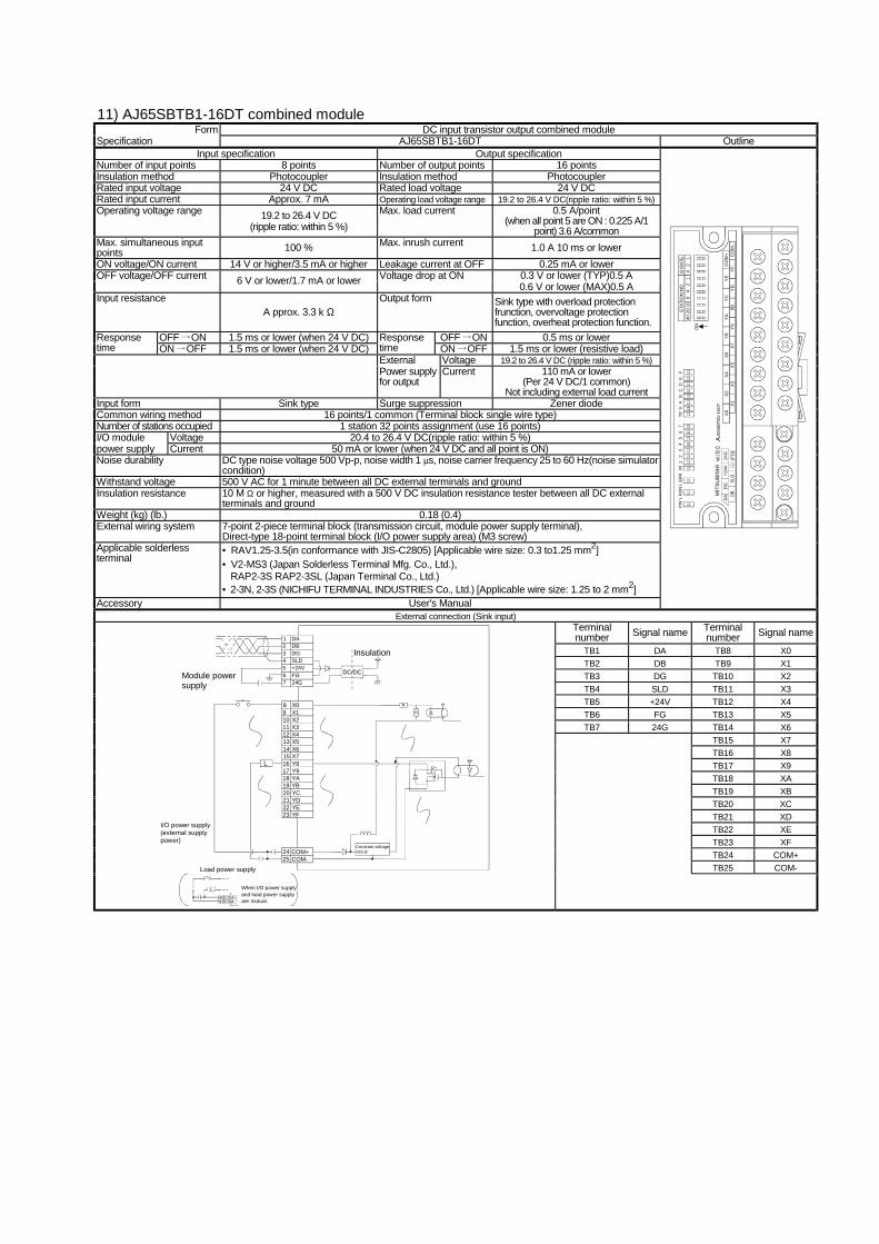
11) AJ65SBTB1-16DT combined module Form DC input transistor output combined module
Specification AJ65SBTB1-16DT Outline Input specification Output specification
Number of input points 8 points Number of output points 16 points Insulation method Photocoupler Insulation method Photocoupler Rated input voltage 24 V DC Rated load voltage 24 V DC Rated input current Approx. 7 mA Operating load voltage range 19.2 to 26.4 V DC(ripple ratio: within 5 %) Operating voltage range 19.2 to 26.4 V DC
(ripple ratio: within 5 %) Max. load current 0.5 A/point
(when all point 5 are ON : 0.225 A/1 point) 3.6 A/common
Max. simultaneous input points 100 % Max. inrush current 1.0 A 10 ms or lower ON voltage/ON current 14 V or higher/3.5 mA or higher Leakage current at OFF 0.25 mA or lower
0.3 V or lower (TYP)0.5 A OFF voltage/OFF current 6 V or lower/1.7 mA or lower Voltage drop at ON 0.6 V or lower (MAX)0.5 A
Input resistance A pprox. 3.3 k Ω
Output form Sink type with overload protection frunction, overvoltage protection function, overheat protection function.
OFF ON 1.5 ms or lower (when 24 V DC) OFF ON 0.5 ms or lower Response time ON OFF 1.5 ms or lower (when 24 V DC)
Response time ON OFF 1.5 ms or lower (resistive load) External Voltage 19.2 to 26.4 V DC (ripple ratio: within 5 %) Power supply for output
Current 110 mA or lower (Per 24 V DC/1 common)
Not including external load current Input form Sink type Surge suppression Zener diode Common wiring method 16 points/1 common (Terminal block single wire type) Number of stations occupied 1 station 32 points assignment (use 16 points) I/O module Voltage 20.4 to 26.4 V DC(ripple ratio: within 5 %) power supply Current 50 mA or lower (when 24 V DC and all point is ON) Noise durability DC type noise voltage 500 Vp-p, noise width 1 µs, noise carrier frequency 25 to 60 Hz(noise simulator
condition) Withstand voltage 500 V AC for 1 minute between all DC external terminals and ground Insulation resistance 10 M Ω or higher, measured with a 500 V DC insulation resistance tester between all DC external
terminals and ground Weight (kg) (lb.) 0.18 (0.4) External wiring system 7-point 2-piece terminal block (transmission circuit, module power supply terminal),
Direct-type 18-point terminal block (I/O power supply area) (M3 screw) Applicable solderless terminal
• RAV1.25-3.5(in conformance with JIS-C2805) [Applicable wire size: 0.3 to1.25 mm2] • V2-MS3 (Japan Solderless Terminal Mfg. Co., Ltd.),
RAP2-3S RAP2-3SL (Japan Terminal Co., Ltd.) • 2-3N, 2-3S (NICHIFU TERMINAL INDUSTRIES Co., Ltd.) [Applicable wire size: 1.25 to 2 mm2]
Accessory User's Manual
X7
X5
X3
X1
Y9
9BY
DY
FY
EY
CY
AY
8X
6X
4X
2X
0
4020
108
42
14
21
B R
ATE
STA
TIO
N N
O.
ON
AJ6
5SBT
B1-1
6DT
DA
DG
+24V
24G
DB
SLD
(FG
)
MIT
SUBI
SHI
PWL
RUN
L ER
RX0
12
34
56
7Y8
9A
BC
DE
F
CO
M+ CO
M-
External connection (Sink input) Terminal number Signal name Terminal
number Signal name
TB1 DA TB8 X0 TB2 DB TB9 X1 TB3 DG TB10 X2 TB4 SLD TB11 X3 TB5 +24V TB12 X4 TB6 FG TB13 X5 TB7 24G TB14 X6
TB15 X7 TB16 X8 TB17 X9 TB18 XA TB19 XB TB20 XC TB21 XD TB22 XE TB23 XF TB24 COM+
TB25 COM-
Module powersupply
DC/DC
DADBDGSLD+24VFG24G
21
34567
Insulation
X0X1X2X3X4X5X6
98
1011121314
X7Y8Y9YAYBYCYD
1615
1718192021
YEYF
2223
L
Constant voltagecircuit
R
R
COM+COM-
2425
I/O power supply(external supplypower)
Load power supply
When I/O power supplyand load power supplyare mutual.
COM+4041 COM-
L
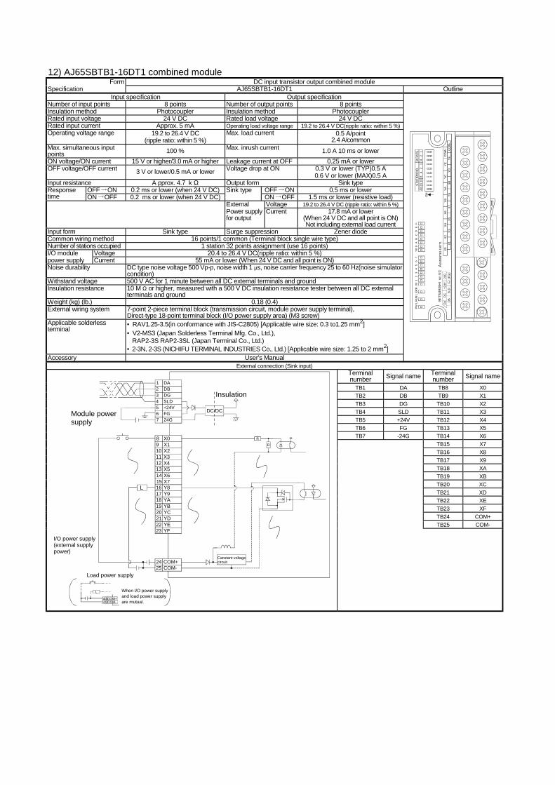
12) AJ65SBTB1-16DT1 combined module Form DC input transistor output combined module
Specification AJ65SBTB1-16DT1 Outline Input specification Output specification
Number of input points 8 points Number of output points 8 points Insulation method Photocoupler Insulation method Photocoupler Rated input voltage 24 V DC Rated load voltage 24 V DC Rated input current Approx. 5 mA Operating load voltage range 19.2 to 26.4 V DC(ripple ratio: within 5 %) Operating voltage range 19.2 to 26.4 V DC
(ripple ratio: within 5 %) Max. load current 0.5 A/point
2.4 A/common Max. simultaneous input points 100 % Max. inrush current 1.0 A 10 ms or lower ON voltage/ON current 15 V or higher/3.0 mA or higher Leakage current at OFF 0.25 mA or lower
0.3 V or lower (TYP)0.5 A OFF voltage/OFF current 3 V or lower/0.5 mA or lower Voltage drop at ON 0.6 V or lower (MAX)0.5 A
Input resistance A pprox. 4.7 k Ω Output form Sink type OFF ON 0.2 ms or lower (when 24 V DC) OFF ON 0.5 ms or lower Response
time ON OFF 0.2 ms or lower (when 24 V DC) Sink type
ON OFF 1.5 ms or lower (resistive load) External Voltage 19.2 to 26.4 V DC (ripple ratio: within 5 %) Power supply for output
Current 17.8 mA or lower (When 24 V DC and all point is ON) Not including external load current
Input form Sink type Surge suppression Zener diode Common wiring method 16 points/1 common (Terminal block single wire type) Number of stations occupied 1 station 32 points assignment (use 16 points) I/O module Voltage 20.4 to 26.4 V DC(ripple ratio: within 5 %) power supply Current 55 mA or lower (When 24 V DC and all point is ON) Noise durability DC type noise voltage 500 Vp-p, noise width 1 µs, noise carrier frequency 25 to 60 Hz(noise simulator
condition) Withstand voltage 500 V AC for 1 minute between all DC external terminals and ground Insulation resistance 10 M Ω or higher, measured with a 500 V DC insulation resistance tester between all DC external
terminals and ground Weight (kg) (lb.) 0.18 (0.4) External wiring system 7-point 2-piece terminal block (transmission circuit, module power supply terminal),
Direct-type 18-point terminal block (I/O power supply area) (M3 screw) Applicable solderless terminal
• RAV1.25-3.5(in conformance with JIS-C2805) [Applicable wire size: 0.3 to1.25 mm2] • V2-MS3 (Japan Solderless Terminal Mfg. Co., Ltd.),
RAP2-3S RAP2-3SL (Japan Terminal Co., Ltd.) • 2-3N, 2-3S (NICHIFU TERMINAL INDUSTRIES Co., Ltd.) [Applicable wire size: 1.25 to 2 mm2]
Accessory User's Manual
X7
X5
X3
X1
Y9
9BY
DY
FY
EY
CY
AY
8X
6X
4X
2X
0
4020
108
42
14
21
B R
ATE
STA
TIO
N N
O.
ON
AJ6
5SBT
B1-1
6DT1
DA
DG
+24V
24G
DB
SLD
(FG
)
MIT
SUBI
SHI
PWL
RUN
L ER
RX0
12
34
56
7Y8
9A
BC
DE
F
CO
M+ CO
M-
External connection (Sink input) Terminal number Signal name Terminal
number Signal name
TB1 DA TB8 X0 TB2 DB TB9 X1 TB3 DG TB10 X2 TB4 SLD TB11 X3 TB5 +24V TB12 X4 TB6 FG TB13 X5 TB7 -24G TB14 X6
TB15 X7 TB16 X8 TB17 X9 TB18 XA TB19 XB TB20 XC TB21 XD TB22 XE TB23 XF TB24 COM+
TB25 COM-
Module power supply
DC/DC
DADBDGSLD+24VFG24G
21
34567
Insulation
X0X1X2X3X4X5X6
98
1011121314
X7Y8Y9YAYBYCYD
1615
1718192021
YEYF
2223
L
Canstant voltagecircuit
R
R
COM+COM-
2425
I/O power supply(external supplypower)
Load power supply
When I/O power supplyand load power supplyare mutual.
COM+4041 COM-
L
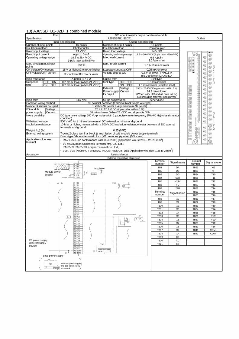
13) AJ65SBTB1-32DT1 combined module Form DC input transistor output combined module
Specification AJ65SBTB1-32DT1 Outline Input specification Output specification
Number of input points 16 points Number of output points 16 points Insulation method Photocoupler Insulation method Photocoupler Rated input voltage 24 V DC Rated load voltage 24 V DC Rated input current Approx. 5 mA Operating load voltage range 19.2 to 26.4 V DC(ripple ratio: within 5 %) Operating voltage range 19.2 to 26.4 V DC
(ripple ratio: within 5 %) Max. load current 0.5 A/point
3.6 A/common Max. simultaneous input points 100 % Max. inrush current 1.0 A 10 ms or lower ON voltage/ON current 15 V or higher/3.0 mA or higher Leakage current at OFF 0.25 mA or lower
0.3 V or lower (TYP)0.5 A OFF voltage/OFF current 3 V or lower/0.5 mA or lower Voltage drop at ON 0.6 V or lower (MAX)0.5 A
Input resistance A pprox. 4.7 k Ω Output form Sink type OFF ON 0.2 ms or lower (when 24 V DC) OFF ON 0.5 ms or lower Response
time ON OFF 0.2 ms or lower (when 24 V DC) Sink type
ON OFF 1.5 ms or lower (resistive load) External Voltage 19.2 to 26.4 V DC (ripple ratio: within 5 %) Power supply for output
Current 24.2 mA or lower (When 24 V DC and all point is ON) Not including external load current
Input form Sink type Surge suppression Zener diode Common wiring method 32 points/1 common (Terminal block single wire type) Number of stations occupied 1 station 32 points assignment (use 32 points) I/O module Voltage 20.4 to 26.4 V DC(ripple ratio: within 5 %) power supply Current 60 mA or lower (When 24 V DC and all point is ON) Noise durability DC type noise voltage 500 Vp-p, noise width 1 µs, noise carrier frequency 25 to 60 Hz(noise simulator
condition) Withstand voltage 500 V AC for 1 minute between all DC external terminals and ground Insulation resistance 10 M Ω or higher, measured with a 500 V DC insulation resistance tester between all DC external
terminals and ground Weight (kg) (lb.) 0.25 (0.55) External wiring system 7-point 2-piece terminal block (transmission circuit, module power supply terminal),
Direct-type 34-point terminal block (I/O power supply area) (M3 screw) Applicable solderless terminal
• RAV1.25-3.5(in conformance with JIS-C2805) [Applicable wire size: 0.3 to1.25 mm2] • V2-MS3 (Japan Solderless Terminal Mfg. Co., Ltd.),
RAP2-3S RAP2-3SL (Japan Terminal Co., Ltd.) • 2-3N, 2-3S (NICHIFU TERMINAL INDUSTRIES Co., Ltd.) [Applicable wire size: 1.25 to 2 mm2]
Accessory User's Manual
4020
108
42
14
21
B R
ATE
STA
TIO
N N
O.
ON Y1
9Y1
7Y1
5Y1
3YB
YDYF
CO
M-
CO
M+
YEYC
YAY1
8Y1
6Y1
4Y1
2X7
X5X3
X1X9
XBXD
XFY1
1Y1
0XE
XCXA
X8X6
X4X2
X0
PWL
RU
NL
ER
RX0
12
34
56
7X8
9A
BC
DE
F
AJ6
5SB
TB1-
32D
T1D
AD
G+2
4V24
GD
BSL
D(F
G)
MIT
SUBI
SHI
Y101
112
1314
1516
17Y1
819
1A1B
1C1D
1E1F
External connection (Sink input) Terminal number Signal name Terminal
number Signal name
TB1 DA TB22 XE TB2 DB TB23 XF TB3 DG TB24 Y10 TB4 SLD TB25 T11 TB5 +24V TB26 Y12 TB6 FG TB27 Y13 TB7 24G TB28 Y14
TB29 Y15 Terminal number Signal name
TB30 Y16 TB8 X0 TB31 Y17 TB9 X1 TB32 Y18 TB10 X2 TB33 Y19 TB11 X3 TB34 Y1A TB12 X4 TB35 Y1B TB13 X5 TB36 Y1C TB14 X6 TB37 Y1D TB15 X7 TB38 Y1E TB16 X8 TB39 Y1F TB17 X9 TB40 COM+ TB18 XA TB41 COM- TB19 XB TB20 XC TB21 XD
Module powersuooky DC/DC
DADBDGSLD+24VFG24G
21
34567
Insulation
X0X1X2X3X4X5X6
1011121314
X7X8X9XAXB
1615
171819
XC20XDXEXFY10Y11
2221
232425
Y1226Y13Y14Y15Y16Y17
2827
293031
Y1832Y19Y1AY1BY1CY1D
3433
353637
Y1E38Y1FCOM+COM-
4039
41
89
L
Constant voltagecircuit
R
R
I/O power supply(external supplypower)
Load power supply
When I/O power supplyand load power supplyare mutual.
COM+4041 COM-
L
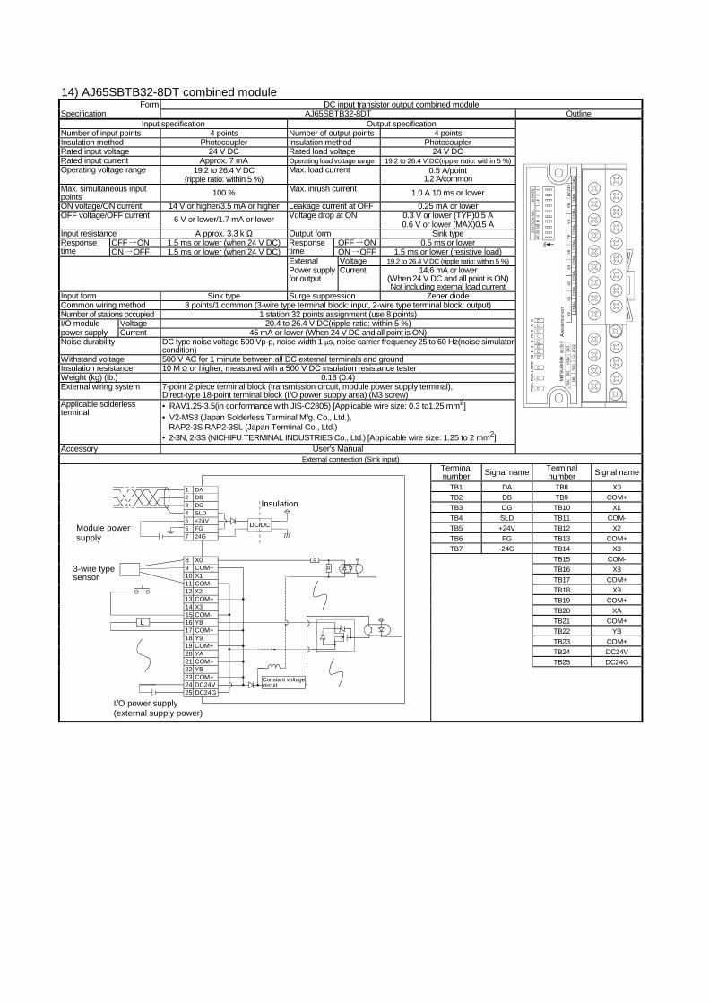
14) AJ65SBTB32-8DT combined module Form DC input transistor output combined module
Specification AJ65SBTB32-8DT Outline Input specification Output specification
Number of input points 4 points Number of output points 4 points Insulation method Photocoupler Insulation method Photocoupler Rated input voltage 24 V DC Rated load voltage 24 V DC Rated input current Approx. 7 mA Operating load voltage range 19.2 to 26.4 V DC(ripple ratio: within 5 %) Operating voltage range 19.2 to 26.4 V DC
(ripple ratio: within 5 %) Max. load current 0.5 A/point
1.2 A/common Max. simultaneous input points 100 % Max. inrush current 1.0 A 10 ms or lower ON voltage/ON current 14 V or higher/3.5 mA or higher Leakage current at OFF 0.25 mA or lower
0.3 V or lower (TYP)0.5 A OFF voltage/OFF current 6 V or lower/1.7 mA or lower Voltage drop at ON 0.6 V or lower (MAX)0.5 A
Input resistance A pprox. 3.3 k Ω Output form Sink type OFF ON 1.5 ms or lower (when 24 V DC) OFF ON 0.5 ms or lower Response
time ON OFF 1.5 ms or lower (when 24 V DC) Response time ON OFF 1.5 ms or lower (resistive load) External Voltage 19.2 to 26.4 V DC (ripple ratio: within 5 %) Power supply for output
Current 14.6 mA or lower (When 24 V DC and all point is ON) Not including external load current
Input form Sink type Surge suppression Zener diode Common wiring method 8 points/1 common (3-wire type terminal block: input, 2-wire type terminal block: output) Number of stations occupied 1 station 32 points assignment (use 8 points) I/O module Voltage 20.4 to 26.4 V DC(ripple ratio: within 5 %) power supply Current 45 mA or lower (When 24 V DC and all point is ON) Noise durability DC type noise voltage 500 Vp-p, noise width 1 µs, noise carrier frequency 25 to 60 Hz(noise simulator
condition) Withstand voltage 500 V AC for 1 minute between all DC external terminals and ground Insulation resistance 10 M Ω or higher, measured with a 500 V DC insulation resistance tester Weight (kg) (lb.) 0.18 (0.4) External wiring system 7-point 2-piece terminal block (transmission circuit, module power supply terminal),
Direct-type 18-point terminal block (I/O power supply area) (M3 screw) Applicable solderless terminal
• RAV1.25-3.5(in conformance with JIS-C2805) [Applicable wire size: 0.3 to1.25 mm2] • V2-MS3 (Japan Solderless Terminal Mfg. Co., Ltd.),
RAP2-3S RAP2-3SL (Japan Terminal Co., Ltd.) • 2-3N, 2-3S (NICHIFU TERMINAL INDUSTRIES Co., Ltd.) [Applicable wire size: 1.25 to 2 mm2]
Accessory User's Manual
CO
M-
CO
M+
CO
M-
CO
M+
CO
M+
CO
M+
CO
M+
CO
M+
DC
24G
DC
24V
YBYA
Y9Y8
X3X2
X1X0
4020
108
42
14
21
B R
ATE
STAT
ION
NO
.
ON
PWL
RU
NL
ERR
X01
23
Y89
AB
AJ6
5SBT
B32-
8DT
DADG
+24V
24G
DBSL
D(F
G)
MIT
SUBI
SHI
External connection (Sink input) Terminal number Signal name Terminal
number Signal name
TB1 DA TB8 X0 TB2 DB TB9 COM+ TB3 DG TB10 X1 TB4 SLD TB11 COM- TB5 +24V TB12 X2 TB6 FG TB13 COM+ TB7 -24G TB14 X3
TB15 COM- TB16 X8 TB17 COM+ TB18 X9 TB19 COM+ TB20 XA TB21 COM+ TB22 YB TB23 COM+ TB24 DC24V
TB25 DC24G
Module powersupply
DC/DC
DADBDGSLD+24VFG24G
21
34567
Insulation
X0COM+X1COM-X2COM+X3
98
1011121314
COM-Y8COM+Y9COM+YACOM+
1615
1718192021
YBCOM+DC24VDC24G
22232425
L
R
R3-wire type sensor
I/O power supply(external supply power)
Constant voltagecircuit
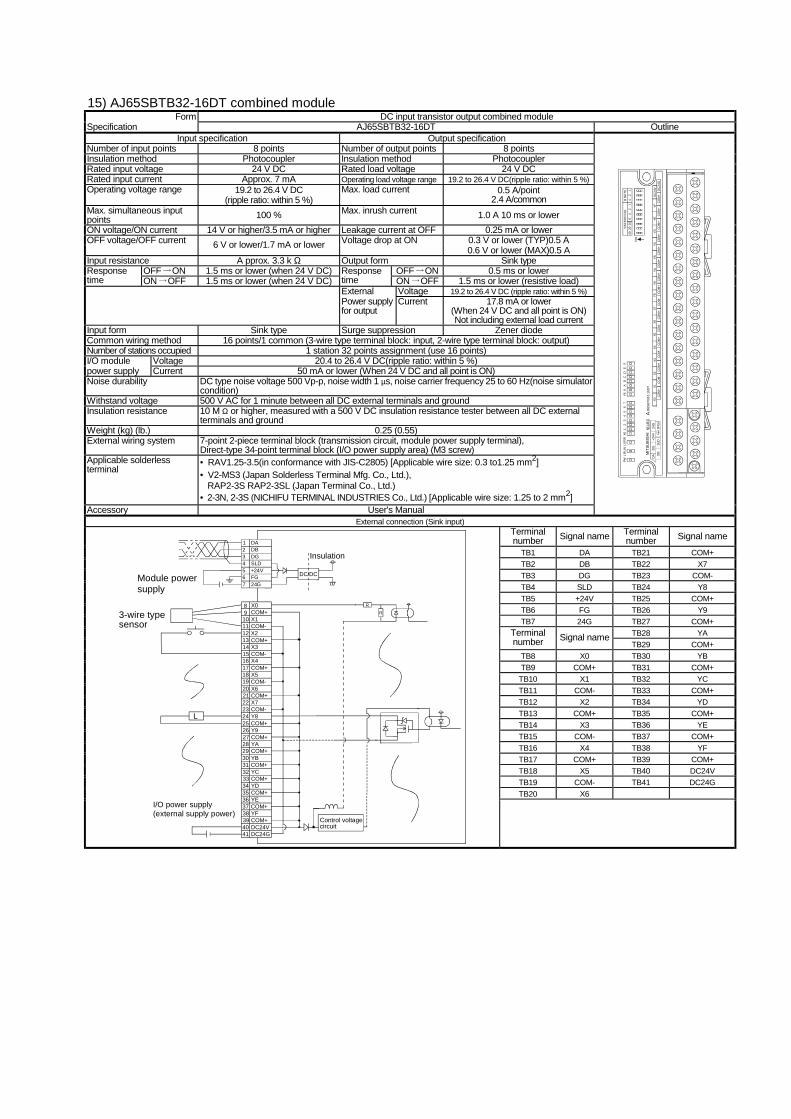
15) AJ65SBTB32-16DT combined module Form DC input transistor output combined module
Specification AJ65SBTB32-16DT Outline Input specification Output specification
Number of input points 8 points Number of output points 8 points Insulation method Photocoupler Insulation method Photocoupler Rated input voltage 24 V DC Rated load voltage 24 V DC Rated input current Approx. 7 mA Operating load voltage range 19.2 to 26.4 V DC(ripple ratio: within 5 %) Operating voltage range 19.2 to 26.4 V DC
(ripple ratio: within 5 %) Max. load current 0.5 A/point
2.4 A/common Max. simultaneous input points 100 % Max. inrush current 1.0 A 10 ms or lower ON voltage/ON current 14 V or higher/3.5 mA or higher Leakage current at OFF 0.25 mA or lower
0.3 V or lower (TYP)0.5 A OFF voltage/OFF current 6 V or lower/1.7 mA or lower Voltage drop at ON 0.6 V or lower (MAX)0.5 A
Input resistance A pprox. 3.3 k Ω Output form Sink type OFF ON 1.5 ms or lower (when 24 V DC) OFF ON 0.5 ms or lower Response
time ON OFF 1.5 ms or lower (when 24 V DC) Response time ON OFF 1.5 ms or lower (resistive load) External Voltage 19.2 to 26.4 V DC (ripple ratio: within 5 %) Power supply for output
Current 17.8 mA or lower (When 24 V DC and all point is ON) Not including external load current
Input form Sink type Surge suppression Zener diode Common wiring method 16 points/1 common (3-wire type terminal block: input, 2-wire type terminal block: output) Number of stations occupied 1 station 32 points assignment (use 16 points) I/O module Voltage 20.4 to 26.4 V DC(ripple ratio: within 5 %) power supply Current 50 mA or lower (When 24 V DC and all point is ON) Noise durability DC type noise voltage 500 Vp-p, noise width 1 µs, noise carrier frequency 25 to 60 Hz(noise simulator
condition) Withstand voltage 500 V AC for 1 minute between all DC external terminals and ground Insulation resistance 10 M Ω or higher, measured with a 500 V DC insulation resistance tester between all DC external
terminals and ground Weight (kg) (lb.) 0.25 (0.55) External wiring system 7-point 2-piece terminal block (transmission circuit, module power supply terminal),
Direct-type 34-point terminal block (I/O power supply area) (M3 screw) Applicable solderless terminal
• RAV1.25-3.5(in conformance with JIS-C2805) [Applicable wire size: 0.3 to1.25 mm2] • V2-MS3 (Japan Solderless Terminal Mfg. Co., Ltd.),
RAP2-3S RAP2-3SL (Japan Terminal Co., Ltd.) • 2-3N, 2-3S (NICHIFU TERMINAL INDUSTRIES Co., Ltd.) [Applicable wire size: 1.25 to 2 mm2]
Accessory User's Manual
4020
108
42
14
21
B R
ATE
STA
TIO
N N
O.
ON
CO
M+
CO
M+
CO
M+
CO
M+
CO
M+
CO
M+
CO
M+
DC
24G
DC
24V
YFYE
YDYC
YBYA
Y9C
OM
-C
OM
+C
OM
-C
OM
+C
OM
+C
OM
-C
OM
+C
OM
-C
OM
+Y8
X7X6
X5X4
X3X2
X1X0
PWL
RU
NL
ER
RX0
12
34
56
7Y8
9A
BC
DE
F
AJ6
5SB
TB32
-16D
TD
AD
G+2
4V24
GD
BSL
D(F
G)
MIT
SUBI
SHI
External connection (Sink input) Terminal number Signal name Terminal
number Signal name
TB1 DA TB21 COM+ TB2 DB TB22 X7 TB3 DG TB23 COM- TB4 SLD TB24 Y8 TB5 +24V TB25 COM+ TB6 FG TB26 Y9 TB7 24G TB27 COM+
TB28 YA Terminal number Signal name
TB29 COM+ TB8 X0 TB30 YB TB9 COM+ TB31 COM+
TB10 X1 TB32 YC TB11 COM- TB33 COM+ TB12 X2 TB34 YD TB13 COM+ TB35 COM+ TB14 X3 TB36 YE TB15 COM- TB37 COM+ TB16 X4 TB38 YF TB17 COM+ TB39 COM+ TB18 X5 TB40 DC24V TB19 COM- TB41 DC24G TB20 X6
Module powersupply
DC/DC
DADBDGSLD+24VFG24G
21
34567
Insulation
X0COM+X1COM-X2COM+X3
1011121314
COM-X4COM+X5COM-
1615
171819
X620COM+X7COM-Y8COM+
2221
232425
Y926COM+YACOM+YBCOM+
2827
293031
YC32COM+YDCOM+YECOM+
3433
353637
YF38COM+DC24VDC24G
4039
41
89
R
R
L
Control voltagecircuit
I/O power supply(external supply power)
3-wire type sensor
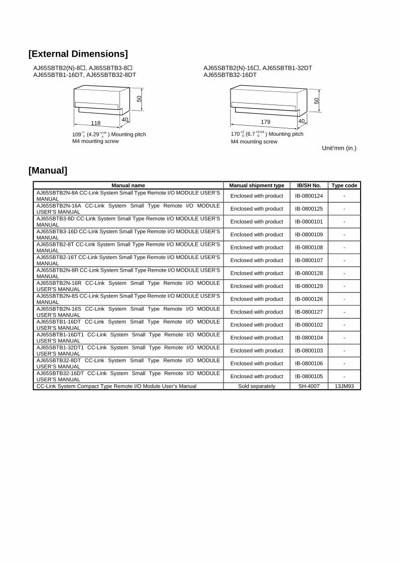
[External Dimensions]
AJ65SBTB2(N)-8!, AJ65SBTB3-8! AJ65SBTB1-16DT, AJ65SBTB32-8DT
118 40
50109+1
0 (4.29 ) Mounting pitch +0.04 0
M4 mounting screw
AJ65SBTB2(N)-16!, AJ65SBTB1-32DT AJ65SBTB32-16DT
179 40
50
170 (6.7 ) Mounting pitch+2 0
+0.04 0
M4 mounting screw Unit’mm (in.)
[Manual]
Manual name Manual shipment type IB/SH No. Type code AJ65SBTB2N-8A CC-Link System Small Type Remote I/O MODULE USER’S MANUAL Enclosed with product IB-0800124 -
AJ65SBTB2N-16A CC-Link System Small Type Remote I/O MODULE USER’S MANUAL Enclosed with product IB-0800125 -
AJ65SBTB3-8D CC-Link System Small Type Remote I/O MODULE USER’S MANUAL Enclosed with product IB-0800101 -
AJ65SBTB3-16D CC-Link System Small Type Remote I/O MODULE USER’S MANUAL Enclosed with product IB-0800109 -
AJ65SBTB2-8T CC-Link System Small Type Remote I/O MODULE USER’S MANUAL Enclosed with product IB-0800108 -
AJ65SBTB2-16T CC-Link System Small Type Remote I/O MODULE USER’S MANUAL Enclosed with product IB-0800107 -
AJ65SBTB2N-8R CC-Link System Small Type Remote I/O MODULE USER’S MANUAL Enclosed with product IB-0800128 -
AJ65SBTB2N-16R CC-Link System Small Type Remote I/O MODULE USER’S MANUAL Enclosed with product IB-0800129 -
AJ65SBTB2N-8S CC-Link System Small Type Remote I/O MODULE USER’S MANUAL Enclosed with product IB-0800126 -
AJ65SBTB2N-16S CC-Link System Small Type Remote I/O MODULE USER’S MANUAL Enclosed with product IB-0800127 -
AJ65SBTB1-16DT CC-Link System Small Type Remote I/O MODULE USER’S MANUAL Enclosed with product IB-0800102 -
AJ65SBTB1-16DT1 CC-Link System Small Type Remote I/O MODULE USER’S MANUAL Enclosed with product IB-0800104 -
AJ65SBTB1-32DT1 CC-Link System Small Type Remote I/O MODULE USER’S MANUAL Enclosed with product IB-0800103 -
AJ65SBTB32-8DT CC-Link System Small Type Remote I/O MODULE USER’S MANUAL Enclosed with product IB-0800106 -
AJ65SBTB32-16DT CC-Link System Small Type Remote I/O MODULE USER’S MANUAL Enclosed with product IB-0800105 -
CC-Link System Compact Type Remote I/O Module User’s Manual Sold separately SH-4007 13JM93

00 (MEE) Specifications subject to change without notice. Printed in Japan on recycled paper.
Country/Region Sales office Tel/Fax U.S.A Mitsubishi Electric Automation Inc.
500 Corporate Woods Parkway Vernon Hills, IL 60061 Tel : 1-847-478-2100 Fax : 1-847-478-0328
Brazil MELCO-TEC Rep. Com.e Assessoria Tecnica Ltda. Av. Rio Branco, 123-15 ,and S/1507, Rio de Janeiro, RJ CEP 20040-005, Brazil
Tel : 55-21-221-8343 Fax : 55-21-221-9388
Germany Mitsubishi Electric Europe B.V. German Branch Gothaer Strasse 8 D-40880 Ratingen, GERMANY
Tel : 49-2102-486-0 Fax : 49-2102-486-717
U.K Mitsubishi Electric Europe B.V. UK Branch Travellers Lane, Hatfield, Herts., AL10 8XB,UK
Tel : 44-1707-276100 Fax : 44-1707-278695
Italy Mitsubishi Electric Europe B.V. Italian Branch Centro Dir. Colleoni, Pal. Perseo - Ingr.2 Via Paracelso 12, 20041 Agrate B., Milano, Italy
Tel : 39-039-6053301 Fax : 39-039-6053206
Spain Mitsubishi Electric Europe B.V. Spanish Branch Pol. Ind. "Can Magi"- C/.Joan Buscalla, 2-4-A.C.420 08190 Sant Cugat del Valles, Barcelona, Spain
Tel : 34-935-653135 Fax : 34-935-891579
South Africa MSA Manufacturing (Pty) Ltd. P O Box 39733 Bramley 201 8 Johannesburg, South Africa
Tel : 27-11-444-8080 Fax : 27-11-444-8304
Hong Kong Ryoden International Ltd. 10th Floor, Manulife Tower, 169 Electric Road, North Point, HongKong
Tel : 852-2887-8870 Fax : 852-2887-7984
China Ryoden International Shanghai Ltd. 3F Block5 Building Automation Instrumentation Plaza 103 Cao Bao Rd. Shanghai 200233 China
Tel : 86-21-6475-3228 Fax : 86-21-6484-6996
Taiwan Setsuyo Enterprise Co., Ltd. 6F., No.105 Wu-Kung 3rd.RD, Wu-Ku Hsiang, Taipei Hsine, Taiwan R.O.C.
Tel : 886-2-2299-2499 Fax : 886-2-2299-2509
Korea STC Techno Seoul Co., Ltd. 1F Dong Seo Game Channel Bldg., 660-11,Deungchon-dong Kangsec-ku, Seoul, Korea
Tel : 82-2-3668-6567 Fax : 82-2-3664-8335
Singapore Mitsubishi Electric Asia Pte, Ltd. 307 ALEXANDRA ROAD #05-01/02, MITSUBISHI ELECTRIC BUILDING SINGAPORE 159943
Tel : 65-473-2480 Fax : 65-476-7439
Thailand F. A. Tech Co.,Ltd. 1138/33-34 Rama 3 Road, Yannawa, Bangkok 10120, Thailand
Tel : 66-2-295-2861 Fax : 66-2-295-2865
Indonesia P.T. Autoteknindo SUMBER MAKMUR Kompleks Agung Sedayu Propertindo (Harco Mangga Dua) Blok H No.4 JI Mangga Dua Raya Jakarta Pusat 10730-Indonesia.
Tel : 62-21-336292 Fax : 62-21-330378
India Messung Systems Put,Ltd. Electronic Sadan NO:111 Unit No15, M.I.D.C BHOSARI,PUNE-411026
Tel : 91-20-7128927 Fax : 91-20-7128108
Australia Mitsubishi Electric Australia Pty. Ltd. 348 Victoria Road, PostalBag, No 2, Rydalmere, N.S.W 2116, Australia
Tel : 61-2-9684-7777 Fax : 61-2-9684-7245
HEAD OFFICE:MITSUBISHI DENKI BLDG MARUNOUCHI TOKYO 100-8310 TELEX:J24532 CABLE MELCO TOKYO