mixer basics primer - marki microwave
TRANSCRIPT

Markimicrowave
Mixer Basics PrimerA Tutorial for RF amp Microwave Mixers
by Ferenc Marki amp Christopher Marki PhD
copy 2010 Marki Microwave Inc | 215 Vineyard Court | Morgan Hill CA 95037
P 4087784200 | F 4087784300 | infomarkimicrowavecom
Markimicrowave
copy 2010 Marki Microwave Inc | 215 Vineyard Court | Morgan Hill CA 95037
P 4087784200 | F 4087784300 | infomarkimicrowavecom
Microwave mixers translate the frequency of electromagnetic signals This functionality is vital for an enormous number of applications ranging from military radar and surveillance to radio astronomy to biological sensing Despite their ubiquity however microwave frequency mixers remain one of the most misunderstood components available in the RFmicrowave engineerrsquos toolbox This Mixer Basics Primer intends to shed light on the ldquodark artrdquo of microwave mixers to help our customers better understand select and ultimately use Marki Microwave mixers
Section 1What is a mixer
A frequency mixer is a 3-port electronic circuit Two of the ports are ldquoinputrdquo ports and the other port is an ldquooutputrdquo port1 The ideal mixer ldquomixesrdquo the two input signals such that the output signal frequency is either the sum (or difference) frequency of the inputs as shown in Fig 1 In other words
The nomenclature for the 3 mixer ports are the Local Oscillator (LO) port the Radio Frequency (RF) port and the Intermediate Frequency (IF) port The LO port is typically driven with either a sinusoidal continuous wave (CW) signal or a square wave signal The choice to apply a CW or square wave signal depends on the application and the mixer Conceptually the LO signal acts as the ldquogaterdquo of the mixer in the sense that the mixer can be considered ldquoONrdquo when the LO is a large voltage and ldquoOFFrdquo when the LO is a small voltage The LO port is usually used as an input port
The other 2 ports of the mixer the RF and IF can be interchanged as either the second input or the output mdashthe actual configuration depends on the application When the desired output frequency is lower than the second input frequency then the process is called downconversion and the RF is the input and the IF is the output The relationship between input and output frequencies is given by
DOWNCONVERSION
Frequency
Radio Frequency(fRF)
Local Oscillator(fLO)
Intermediate Frequency(fIF)
DC
R IL
Pow
er
UPCONVERSIONfIF = |fLO - fRF| fRF1 = fLO - fIF fRF2 = fLO + fIF
RF
LO
IF
Frequency
Radio Frequency(fRF)
Local Oscillator(fLO)
Intermediate Frequency(fIF)
DC
IRL
Pow
er
RF1
LO
IF
RF2
Figure 1 Definitions of downconversion and upconversion
the RF is output A frequency domain representation of downconversion and upconversion is illustrated in Fig 1 Take careful note of the upconversion casemdashthe close proximity of the sum and difference frequencies (fRF1 and fRF2) in the frequency domain implies that both are available at the RF output port This type of upconversion is known as double sideband upconversion Single sideband upconversion is also possible in which case either the sum or the difference frequency is intentionally canceled inside the mixer Mixers that perform this more sophisticated functionality are called single sideband (SSB) upconverters (or single sideband modulators) and will be addressed in a future article
As Fig 1 depicts IFRF signals tend to be information bearing signals (as denoted by the broadened spectra surrounding the RF and IF center frequencies) During frequency conversion the information carried by the RF (IF) signal is frequency translated to the IF (RF) output Therefore mixers perform the critical function of translating in the frequency domain
In principle any nonlinear device can be used to make a mixer circuit As it happens only a few nonlinear devices make ldquogoodrdquo mixers The devices of choice for modern mixer designers are Schottky diodes GaAs FETs and CMOS transistors The choice depends on the application FET and CMOS mixers are typically used in higher volume applications where cost is the main driver and performance is less important For the more challenging high performance applications Schottky diode mixers are used almost exclusively All Marki Microwave mixers are designed using Schottky diode technology For this reason this Tutorial will focus on
f f fout in1 in2= (1)
f | f f |IF LO RF= - (2)
On the other hand when the desired output frequency is higher than the second input frequency then the process is called upconversion and the IF is the input and 1Actually all three ports of a mixer behave as both a load and a source We will ignore this fact for the moment and save it for a later discussion An excellent resource on this topic can be found in [1]
Markimicrowave
copy 2010 Marki Microwave Inc | 215 Vineyard Court | Morgan Hill CA 95037
P 4087784200 | F 4087784300 | infomarkimicrowavecom
Ideal Commutator
Voltage
Cur
rent
VRF
VLO
VIF
ndash
+
(a)
(b) (c)
Actual Schottky Diode
TransitionRegion
Voltage
Cur
rent
diode mixers with only tacit reference to transistor-type mixers
Figure 2 (a) Simple single ended mixer I-V characteristics for (b) the ideal commutator and (c) a realistic Schottky diode
Section 2Single Diode Mixer Ideal Commutator vs Realistic Diode
There are many ways to build a mixer The simplest mixer consists of a single diode as shown in Fig 2a A large signal LO and a small signal RF combine at the anode of the diode For an ldquoidealrdquo single diode mixer it is assumed that the LO is significantly stronger than the RF such that only the LO has the ability to affect the transconductance of the diode We also assume that the diode switches instantaneously as shown in Fig 2b Devices that possess such instantaneous transconductance switching are called ideal commutators and yield the theoretically optimal diode mixer performance
The ldquomixingrdquo process takes place due to the switching response of the diode I-V curve to the strong LO signal As the diode is forced open and closed by the LO the small signal RF is ldquochoppedrdquo When we analyze the Fourier components of the output signal from a commutating (or switching) mixer diode (Fig 3a and Fig 3c) we find that the possible output products follow the relation
(a) Ideal CommutatorTime Domain
025
02
015
01
005
0002 201816141210080604
10
0
-10
-20
-30
-40
-50
-60
-70
10
0
-10
-20
-30
-40
-50
-60
-70405 10 15 20 25 30 35
(b) Realistic DiodeTime Domain
(c) Ideal CommutatorFrequency Domain
Rel
ativ
e A
mp
litud
e (d
B)
Rel
ativ
e A
mp
litud
e (d
B)
IF
LORF
(d) Realistic DiodeFrequency Domain
025
02
015
01
005
0002 201816141210080604
0 405 10 15 20 25 30 350
Figure 3 Time and frequency domain comparing the output of the single ended mixer in Figure 2 with ideal and relatistic diode switching characteristics
commutator only odd harmonics of the LO are allowed to mix with the fundamental RF tone
Unfortunately the transfer function of the ideal commutator can never be achieved in the real world Actual Schottky diodes necessarily possess some amount of ldquoturn-onrdquo transition as shown in Fig 2c Moreover the RF will modulate the diode transconductance to some extentmdasheven if the RF is very small The combination of realistic diode I-V characteristics and transconductance modulation by the RF signal causes additional mixing products (often referred to as ldquospursrdquo) Thus real diodes produce all possible harmonic mixing components The time domain signal and associated frequency spectrum generated by a realistic Schottky diode are depicted in Fig 3b and Fig 3d Mathematically the frequency components generated by a single diode are given by
f nf f (n is ODDonly)IF LO RF= (3)
Thus in the ideal case of a perfectly switching
f nf plusmnmf mandnare ALL integersIF LO RF= ^ h (4)
Because we only want one desired output frequency (when n=1 and m=1) the existence of all other harmonic terms creates significant problems Elimination of these distortion products is a key goal in mixer design
This simplified analysis illustrates several important
Markimicrowave
copy 2010 Marki Microwave Inc | 215 Vineyard Court | Morgan Hill CA 95037
P 4087784200 | F 4087784300 | infomarkimicrowavecom
attributes of frequency mixers1 ldquoMixingrdquo is caused by the switching behavior of the
diode2 The majority of unwanted harmonics are caused
by the nonlinear intermodulation of the RF and LO signals in the transition region of the diode
3 The best mixers use diodes that closely approximate the ideal commutator
4 The lower the RF power the better the spurious performance (since the LO will control the diode transconductance more effectively)
Section 3 Mixer Balance
High performance mixers are designed using four or eight diodes The evolution of the mixer circuit from the single diode unbalanced type to the multi-diode balanced type is described in this Section Much of this information is a summary of [2]
Sophisticated mixer designs make use of circuit symmetry to create ldquobalancerdquo In fact virtually all commerically available mixers make use of some kind of mixer balancing Mixer balancing offers several advantages inherent isolation among all mixer ports (and hence band flexibility) cancellation of most intermodulation
4-PortHybrid Junction
Port 1
Input
Isolated
Port 4
Input2
-Input2
Port 3
Input2
Input2
Port 2
Isolated
Input
1
2
3
4
4-PortHybrid Junction
LO
RF
IF
Figure 5 Single balanced mixer with 4-port hybrid junction
Figure 4 Schematic and IO table for a 4-port hybrid junction
products common mode signal rejection and improved conversion efficiency
In mixers extra circuitry is needed to route and separate (ie multiplex) input and output signals from the diodesmdashsuch is the cost for using a two terminal device to perform a three-port functionality In single diode mixers this extra circuitry consists of a combination of passive coupling power division and filtering It is difficult to create wideband single diode mixers with independent RF LO and IF bands since the multiplexing circuitry is frequency specific Moreover such circuitry causes extra losses that reduce mixer efficiency
To solve this problem clever engineers realized that wideband single-balanced mixers with low loss and independent input and output frequency bands could be created using the classic four port hybrid junction The hybrid junction (aka the ldquomagic teerdquo or the 180o
hybrid) depicted in Fig 4 is a two input two output four port circuit that provides mutual isolation between input ports and equal power division at the output ports One immediately sees the applicability of the hybrid junction for mixers the input LO and RF sources will be isolated from one another thus providing frequency band independence and equal power division to the load The inputoutput transfer characteristics are listed in Fig 4 Notice that the output signals are differentially phased (ie 180o phase shifted) when a signal is input to port 2 Output signals are in phase for inputs into port 1
The hybrid junction provides a natural method by which to create the single balanced mixer as shown in Fig 5 Additionally two diodes are used instead of one Key features of the single balanced mixer include1 Isolation (and hence frequency independence)
between RF and LO ports2 50 reduction in the total number of intermodulation
products3 Common mode noise cancellation (good for noisy
LO)4 Higher conversion efficiency than the single diode
mixer
Further two single balanced mixers can combine to form the double balanced mixer as shown in Fig 6 In this case hybrid junctions are placed on both the RF and LO differential ports and the IF is obtained at the
Markimicrowave
copy 2010 Marki Microwave Inc | 215 Vineyard Court | Morgan Hill CA 95037
P 4087784200 | F 4087784300 | infomarkimicrowavecom
in phase port of the hybrid junctionmdashThe reciprocity of the hybrid junction allows this type of interconnection Detailed analysis reveals that for the double balanced mixer only ODD n and ODD m harmonic spurs can survive at the IF port [1] Therefore mixer double-balancing has the benefit of reducing nearly 75 of the spurious interferers possible at the IF port Owing to conservation of energy double balanced mixers tend to have better conversion efficiency than single ended or single balanced mixers since energy cannot spread into the EVEN order harmonics
A more complex mixer circuit is created using two double balanced mixers driven in a push-pull configuration (Fig 7) This ldquodoubly double balancedrdquo mixer has received the ill-conceived title of the ldquotriple balancedrdquo mixer Some of the key features of the triple balanced mixer are overlapping RF LO and IF bands and higher spurious suppression Marki Microwave T3 mixers are a special subset of triple balanced mixers and provide the highest spurious suppression possible by closely emulating the ideal commutator switching behavior The details and analysis of the T3 mixer are available in [3]
Section 4 Mixer Performance Metrics
What makes a ldquogoodrdquo mixer Wellmdashlots of things We will now address some of the criteria by which to judge and ultimately choose a mixer
A Conversion Loss
The most important mixer metric is conversion loss Conversion loss is defined as the difference in power between the input RF power level and the desired output IF frequency power level In other words
CL P PRF IF= -
where PRF and PIF are in dBm and CL is in dB For example if the input RF is -10 dBm and the downconverted IF output signal -17 dBm then the conversion loss is 7 dB The theoretically optimum conversion loss for a passive diode mixer is 39 dB and can be calculated using equa-tions derived by Henderson [4] Typical values of conver-sion loss range between about 45 to 9 dB depending on the mixermdashthe additional losses are caused by fac-tors such as transmission line losses balun mismatch di-ode series resistance and mixer (im)balance In general double balanced mixers have less conversion loss than triple balanced mixers because of circuit losses Another important trend is that wider bandwidth mixers tend to have higher conversion loss in part due to the difficulty in maintaining circuit balance over the entire bandwidth
Conversion loss is the benchmark mixer metric because it correlates closely with other metrics like isolation and 1 dB compression Experience shows that for a mature mixer design such as the Marki Microwave M1-0220 a single conversion loss measurement will indicate the quality of the unit If the conversion loss of a unit is within a narrow specification all other performance metrics will also meet specifications The converse is not necessarily true however it is possible to have good isolation and poor conversion loss for example Because conversion loss is the benchmark measurement for all mixers Marki Microwave tests the conversion loss of all mixers produced in the facility
B Isolation
Isolation is a measure of the amount of power that leaks from one mixer port to another As was described
(5)
4-PortHybrid Junction
LO RF
IF
4-PortHybrid Junction
Figure 6 Double balanced mixer
Figure 7 Doubly double balanced mixer (aka triple balanced mixer)
LO∆ ∆
∆ ∆
∆
sum sum
sum
sum
sum
RF
IF
4-PortHybrid
Junction
4-PortHybrid
Junction
4-PortHybrid
Junction
4-PortHybrid
Junction
4-Po
rtH
ybri
dJu
ncti
on
Markimicrowave
copy 2010 Marki Microwave Inc | 215 Vineyard Court | Morgan Hill CA 95037
P 4087784200 | F 4087784300 | infomarkimicrowavecom
previously port isolation is obtained through mixer balance and the use of hybrid junctions Unfortunately there will always be some small amount of power leakage between the RF LO and IF ports Isolation is the difference in power between the input signal and the leaked power to the other ports In other words if we place an input signal at the LO port and measure the power available at the RF port at that LO frequency the isolation in dB is given by
P P PISO (L R) in(LO) out(RF)= --
Note that isolation is approximately reciprocal the port 1 to port 2 isolation will track closely with the port 2 to port 1 isolation Hence a single measurement can be performed to determine the isolation in both directions Three types of isolation are commonly quoted in microwave mixers L-R isolation L-I isolation and R-I isolation The definitions of each type of isolation are illustrated in Fig 8
L-R isolation is the leakage of the LO into the RF port Typical L-R isolation values range between about 25-35 dB L-R isolation is critical in frequency downconversions because LO power can leak into the RF circuitry If there is poor L-R isolation LO power can contaminate the RF line by either interfering with the RF amplifier or by leaking to other parallel mixing channels causing cross-channel interference Poor L-R isolation can also cause problems in frequency upconversions when the
LO frequency is very close to the RF output frequency (when the IF frequency is at or near DC) In this case no amount of filtering can separate the arbitrarily close RF signal and LO leakage This can result in interference between the RF and LO and a degradation in the RF output circuitry
L-I isolation is the leakage of the LO into the IF port L-I isolation tends to be the worst of the three types of mixer isolation with typical values ranging from 20-30 dB When there is poor L-I isolation the biggest issue occurs when the LO and IF frequencies are close such that the LO contaminates the IF circuitry as when the LO leakage is strong enough to saturate the IF amplifier Beyond this poor L-I isolation can cause conversion loss flatness problems
The final mixer isolation metric is R-I isolation Values of R-I isolation typically range between 25-35 dB Most systems designers will not find R-I isolation to be a major issue since the RF and IF powers tend to be orders of magnitude smaller than the LO power Therefore LO isolation problems are the primary concern of systems engineers R-I isolation instead is a major concern for mixer designers because it serves as a diagnostic metric for the overall conversion efficiency of the mixer circuit When the R-I isolation is high the mixer circuit is well balanced and thus the conversion loss tends to be low In mixers with bad R-I isolation (lt20 dB) the conversion loss is higher and the conversion loss flatness is poor
POUT
PIN LO
POUT RF
ISOL-R
PIN
R IL
Frequency
Pow
er
POUT
PIN
R IL
POUTPIN R IL
PIN LO
POUT IF
ISOL-I
Frequency
Pow
er
PIN RF
POUT IF
ISOR-I
Frequency
Pow
er
Figure 8 Definitions of mixer isolation for L-R L-I and R-I isolation
(6)
Markimicrowave
copy 2010 Marki Microwave Inc | 215 Vineyard Court | Morgan Hill CA 95037
P 4087784200 | F 4087784300 | infomarkimicrowavecom
C 1 dB Compression
Under normal (linear) operation the conversion loss of the mixer will be constant regardless of input RF power If the input RF power increases by 1 dB then the output IF power will also increase by 1 dB (the power difference is the conversion loss) However as the RF power becomes too large this dB for dB relationship will not hold The 1 dB compression point is a measure of the linearity of the mixer and is defined as the input RF power required to increase the conversion loss by 1 dB from ideal
Mixer compression is most easily represented graphically as shown in Fig 9 For low input RF power the slope of the line is 11 as described above However as the RF power increases the mixer deviates from this linear behavior and the conversion loss starts to increase When the inputoutput curve ldquosagsrdquo by 1 dB (ie the conversion loss increases by 1 dB) the input RF 1 dB compression has been reached
Conceptually the 1 dB compression point occurs when the RF signal can no longer be considered ldquosmall signalrdquo Under linear operation the LO power is so much stronger than the RF power that the diode switching action is totally dominated by the LO as described in Section 2 However in compression the RF power competes with the LO power such that the diode switching action is
IF OutputPower (dBm)
Ideal11 Slope
1 dB
MeasuredCurve
RF InputPower (dBm)
ConversionLoss
Input 1 dBCompression Point
Figure 9 Graphical representation of 1 dB compression point
compromised When the RF power is within about 3 dB of 1 dB compression the mixer behaves unpredictably Among other effects operating the mixer in compression causes increased levels of intermodulation distortion and higher conversion loss This behavior is explained by the fact that the compressed mixer spreads energy in the frequency domain because the diodes are being partially turned-on by the RF signal Slight mixer imbalances are therefore exacerbated and the mixer conversion efficiency is degraded
Mixer compression can be improved by using higher turn-on diodes In this way a larger RF power can be applied to the mixer without challenging the turn-on voltage of the diode The trade-off of course is that a larger LO drive must also be applied to switch the diode ON and OFF As a rule of thumb the 1 dB compression point will be anywhere from 4-7 dB below the minimum recommended LO drive level of the mixer For low barrier ldquoLrdquo diodes 1 dB compression occurs for input RF powers gt 0 dBm For super-high barrier ldquoSrdquo diodes 1 dB compression occurs for input RF power gt +12 dBm State-of-the-art mixers such as the T3 series can be driven with any LO power gt15 dBm and the corresponding 1 dB compression point will be 3 to 4 dB below that drive For example a T3 driven with +18 dBm will compress around +15 dBm That same T3 driven with +25 dBm will compress around +22 dBm To our knowledge no other mixer ever created offers the ability to linearly increase the 1 dB compression point simply by increasing the LO drive level
D VSWR
Mixer VSWR is a contentious topic It is our opinion that VSWR is a meaningless metric for microwave mixers because it does not help to predict mixer performance nor does it guarantee proper operation when the mixer is integrated within the surrounding RF system The crux of the argument comes down to the fact that the mixer cannot be modeled as a static load In actuality a mixer is both a load and a source It can be easily shown that all three mixer ports act as sources for the intermodulation distortion intrinsic to the diodes [1] Even if the VSWR of the mixer is perfect (ie no reflections of the fundamental) there will inevitably be harmonics coming out of the input ports
A classic mixer spur problem involves the 2LO x 1RF
Markimicrowave
copy 2010 Marki Microwave Inc | 215 Vineyard Court | Morgan Hill CA 95037
P 4087784200 | F 4087784300 | infomarkimicrowavecom
The overlap of the downconverted image spur and the desired IF creates substantial interference The extent of the interference depends on the relative phase difference between the two signals If the RF frequency is swept the relative phase will cycle from 0 to 2 π resulting in significant conversion loss ripple A common concern is that conversion loss ripple is caused by poor mixer VSWR However as we have illustrated in this example issues associated with the mixer acting as a source of RF and LO products frequently lead to more serious problems if precautions are not taken
Always remember that all Marki Microwave mixer speci-fications are defined assuming wideband 50 Ω systems In our experience mixer VSWR is a minor concern com-pared to the myriad problems that arise when the mixer ports are reactively terminated such as in the above example To solve these problems we recommend in-creasing attenuation or using non-reflective termina-tions such as absorptive WavefadeTM low pass filters or 50 Ω terminated diplexers
E Noise Figure
As long as the quality of the diode is closely monitored the noise figure of the mixer can be approximated by the conversion loss Generally the cumulative noise figure will limit the minimum detectable signal in the
ldquoimagerdquo spur It can be shown that all EVEN LO x ODD RF spurs generated within the mixer are available at the RF port [1] A problem arises when the RF port is reactively terminated with for example a preselection bandpass filter Acting as a source the mixer produces the 2L x 1R image spur which exits the RF port and enters the RF filter Most commonly the 2L x 1R product will lie outside the passband of the filter and will hence be reflected back into the mixer as shown in Fig 10 Upon re-entry into the mixer the 2L x 1R image product will mix with the LO and downconvert to the exact same frequency as the desired difference frequency In other words
f fout IF=
f f fout spur LO= -
f 2 f f fout LO RF LO= - -$
f f fout LO RF= -
receiver Hence when choosing mixers for low power applications conversion loss should be as low as possible
F Single-tone Intermodulation Distortion
Much has already been said about the harmonic mixing products generated by the nonlinear mixing of the RF and LO signal in the transition region of the diode I-V curve as given by (3) and illustrated in Fig 3 Most commonly the only desirable mixing term is given by m=1 and n=1 in (3) and all other unwanted harmonic terms are called single-tone IMD A major goal in mixer design is to limit the strength of the single-tone IMD terms
The key features of single-tone IMD in double and triple balanced mixers are1 Only ODD n by m terms exist at the IF port in double
and triple balanced mixers2 Cancellation through mixer balance improves
EVEN by EVEN EVEN by ODD and ODD by EVEN harmonic levels by about 30 dB
3 The lower the RF input power the better the single-tone spurious performance
4 With the exception of the T3 mixer increasing the LO drive does not always improve spurious performance
Marki Microwave provides typical mixer spur tables for its double balanced triple balanced and T3 mixer lines For additional information on single-tone IMD in double balanced mixers we recommend Bert Hendersonrsquos analysis on the prediction of mixer IMD [4]
Radio Frequency(fRF)
Image Spur2LO x 1RF
Output
Local Oscillator(fLO)
R IL
BPF
OUTPUT SPECTRUM
FilterBandwidth
ImageSpur
LO
RF
IF
Figure 10 Schematic diagram (left) showing backreflected 2LO x 1RF spur from reactive bandpass filter (BPF) Output spectrum (right) showing desired IF and downconverted image spur over-lapping in frequency
(7)
Markimicrowave
copy 2010 Marki Microwave Inc | 215 Vineyard Court | Morgan Hill CA 95037
P 4087784200 | F 4087784300 | infomarkimicrowavecom
G Multi-tone Intermodulation Distortion
Multi-tone IMD implies that multiple tones enter the mixer through the same port and intermodulate in the mixer diodes Multi-tone IMD is a form of common mode mixing in which two or more tones enter the RF port and nonlinearly mix with each other and the LO to create distortion as shown in Fig 11 From the perspective of a system designer multi-tone IMD is a serious problem because it can generate interference tones that fall within the IF bandwidth of the receiver Hence multi-tone IMD places a theoretical upper limit on the dynamic range of the receiver
The efficiency of multi-tone IMD generation is dependent on the intrinsic nonlinear characteristics of the devices (ie diodes FETs etc) and the balance of the mixer The widely accepted figure of merit for mixer multi-tone performance is the two tone third order input intercept point (TOI) Also refered to as ldquotwo-tonerdquo IMD and by the acronym IIP3 TOI is a mathematical construct used in predicting the nonlinear behavior of a mixer as the input RF power increases The generation of two-tone products is illustrated in Fig 12 Two closely spaced signals enter the RF port of the mixer and nonlinearly intermodulate with the LO The possible harmonics available at the mixer IF port are given by the relation
f plusmn nf plusmn m f plusmn m fout LO 1 RF1 2 RF2=
Interferer 2f f fRF1 RF2 LO1 = - -
Interferer 2f f fRF RF LO2 12 = - -
where n m1 and m2 are all integers As is shown in Fig 11 two-tone IMD is troublesome because the generated interference tones
overlap in frequency with the desired downconverted signals No amount of filtering can separate the two-tone interference and thus the signal to noise ratio of the received signal is degraded
While fundamental mixing tones (ie m=1 and n=1) grow by a slope of 1 to 1 with input RF power higher order RF mixing terms grow by a slope of m1 In the case of (7) two-tone IMD grows by a slope of |m1| + |m2| to 1 Hence interference terms in (9a) and (9b) are called third-order IMD products and grow by a slope of 31 as shown in Fig 13 Graphically the input power at which the fundamental (11) line and the interference (31) line intersect is the third order intercept point It is notable
that the TOI is an extrapolated point because the mixer would compress before the lines crossed Nevertheless the impact of the third-order interference products can be debilitating in many systems at RF power well below the 1 dB compression point The higher the TOI the better the mixer
ATTEN 10dBRL OdBm 10 dB
REF LVLOdBm
CENTER 550000GHzbull RBW 30kHz bull VBW 300Hz
SPAN 1000MHzSWP 280sec
ATTEN 10dBRL OdBm 10 dB
REF LVLOdBm
CENTER 550000GHzbull RBW 30kHz bull VBW 300Hz
SPAN 1000MHzSWP 280sec
Figure 11 (Top) Significant multi-tone IMD caused by three in-put RF signals (Bottom) Improved IMD performance using a T3 mixer due to commutating diode behavior
ATTEN 10dBRL OdBm 10 dB
REF LVLOdBm
CENTER 550000GHzbull RBW 30kHz bull VBW 300Hz
SPAN 1000MHzSWP 280sec
ATTEN 10dBRL OdBm 10 dB
REF LVLOdBm
CENTER 550000GHzbull RBW 30kHz bull VBW 300Hz
SPAN 1000MHzSWP 280sec
Typical values of TOI can vary dramatically depending on the mixer type and technology Conventional double balanced and triple balanced mixers tend to have TOI values a few dB above the recommended drive level For example a Marki Microwave M2-0220 triple balanced mixer with medium barrier (ldquoMrdquo) diodes requires at least +13 dBm of LO drive The corresponding TOI at this drive level is +18 dBm For state-of-the-art TOI performance Marki Microwave recommends using the T3 mixer The
(8)
(9a)
(9b)
Markimicrowave
copy 2010 Marki Microwave Inc | 215 Vineyard Court | Morgan Hill CA 95037
P 4087784200 | F 4087784300 | infomarkimicrowavecom
T3 mixer provides unprecendented bandwidth and IMD performance compared to all other mixer lines (offered by Marki or elsewhere) because the diodes are designed to behave much more closely to the ideal commutator described in Section 2 The argument is simple if the RF tones are not capable of switching the diode from the OFF to the ON state as is the case in the ideal commutator then no multi-tone interference is possible This is vividly demonstrated in Fig 11 The graph on the top was measured using a standard double balanced M1 mixer The graph on the bottom was measured using a T3 mixer The commutating diode concept is so powerful that T3 mixers can easily achieve TOI greater than +30 dBm for LO drives below +20 dBm
fRF1
fRF2
fLO
fIF1 amp fIF2
+ Multi-tone IMD
IF1 IF2RF2RF1
Multi-tone Interference
Pow
er
Frequency
LO
R IL
Figure 12 Illustration of multi-tone IMD created by two closely spaced RF signals Generated IMD tones overlap with desired IF1 and IF2 signals
art system designers This is due in part to the fact that RFmicrowave mixer performance is dependent on both the quality of the diodes used and the sophistication of the surrounding circuitry involved The three dimensional microwave hybrid assembly approach employed by Marki Microwave is simply impossible to replace with restrictive two dimensional integrated circuit fabrication techniques For this reason Marki Microwave draws on
over four decades of industry experience to boast the widest selection of high performance RFmicrowave mixers in the world Between our double balanced triple balanced and T3 mixers families there is a perfect mixer choice for any application
Section 6 References
[1] Marki FA ldquoMiniature Image Reject Mixers And Their Use In Low-noise Front-ends In Conjunction With Gaas Fet Amplifiersrdquo Circuits Systems and Computers 1977 Conference Record 1977 11th Asilomar Conference on
OutputPower (dBm)
Extrapolated11 Slope
MeasuredIF
MeasuredIMD
RF InputPower (dBm)
Extrapolated31 Slope
Input Third OrderIntercept Point
Figure 13 Graphical representation to derive input third order intercept point
Section 5 Summary
The sole purpose of the microwave mixer is to provide either the sum or difference frequency of the two incoming signals at the output The goal of a mixer designer is to create a circuit that performs this frequency translation efficiently and without distortion For optimal performance hybrid mixers using Schottky diodes remain the technology of choice for state-of-the-
Markimicrowave
copy 2010 Marki Microwave Inc | 215 Vineyard Court | Morgan Hill CA 95037
P 4087784200 | F 4087784300 | infomarkimicrowavecom
pp 159-162 7-9 Nov 1977 httpwwwmarkimicrowavecommenusappnotesnoisepdf
[2] ldquoMixer Evolution The Balanced Mixer Family Circlerdquo Application Note httpwwwmarkimicrowavecommenusappnotesbalancedpdf
[3] Marki F and Marki C ldquoT3 Mixer Primer A mixer for the 21st Centuryrdquo Marki Microwave Morgan Hill CA httpwwwmarkimicrowavecommenusappnotest3_primerpdf 2010
[4] Henderson B C ldquoPredicting Intermodulation Suppression in Double-Balanced Mixersrdquo Watkins-Johnson Company Technical Notes Vol 10 No 4 JulyAugust 1983
Marki Microwave215 Vineyard CtMorgan Hill CA 95037408-778-4200 (ph)408-778-4300 (fax)infomarkimicrowavecom
Markimicrowave
copy 2010 Marki Microwave Inc | 215 Vineyard Court | Morgan Hill CA 95037
P 4087784200 | F 4087784300 | infomarkimicrowavecom

Markimicrowave
copy 2010 Marki Microwave Inc | 215 Vineyard Court | Morgan Hill CA 95037
P 4087784200 | F 4087784300 | infomarkimicrowavecom
attributes of frequency mixers1 ldquoMixingrdquo is caused by the switching behavior of the
diode2 The majority of unwanted harmonics are caused
by the nonlinear intermodulation of the RF and LO signals in the transition region of the diode
3 The best mixers use diodes that closely approximate the ideal commutator
4 The lower the RF power the better the spurious performance (since the LO will control the diode transconductance more effectively)
Section 3 Mixer Balance
High performance mixers are designed using four or eight diodes The evolution of the mixer circuit from the single diode unbalanced type to the multi-diode balanced type is described in this Section Much of this information is a summary of [2]
Sophisticated mixer designs make use of circuit symmetry to create ldquobalancerdquo In fact virtually all commerically available mixers make use of some kind of mixer balancing Mixer balancing offers several advantages inherent isolation among all mixer ports (and hence band flexibility) cancellation of most intermodulation
4-PortHybrid Junction
Port 1
Input
Isolated
Port 4
Input2
-Input2
Port 3
Input2
Input2
Port 2
Isolated
Input
1
2
3
4
4-PortHybrid Junction
LO
RF
IF
Figure 5 Single balanced mixer with 4-port hybrid junction
Figure 4 Schematic and IO table for a 4-port hybrid junction
products common mode signal rejection and improved conversion efficiency
In mixers extra circuitry is needed to route and separate (ie multiplex) input and output signals from the diodesmdashsuch is the cost for using a two terminal device to perform a three-port functionality In single diode mixers this extra circuitry consists of a combination of passive coupling power division and filtering It is difficult to create wideband single diode mixers with independent RF LO and IF bands since the multiplexing circuitry is frequency specific Moreover such circuitry causes extra losses that reduce mixer efficiency
To solve this problem clever engineers realized that wideband single-balanced mixers with low loss and independent input and output frequency bands could be created using the classic four port hybrid junction The hybrid junction (aka the ldquomagic teerdquo or the 180o
hybrid) depicted in Fig 4 is a two input two output four port circuit that provides mutual isolation between input ports and equal power division at the output ports One immediately sees the applicability of the hybrid junction for mixers the input LO and RF sources will be isolated from one another thus providing frequency band independence and equal power division to the load The inputoutput transfer characteristics are listed in Fig 4 Notice that the output signals are differentially phased (ie 180o phase shifted) when a signal is input to port 2 Output signals are in phase for inputs into port 1
The hybrid junction provides a natural method by which to create the single balanced mixer as shown in Fig 5 Additionally two diodes are used instead of one Key features of the single balanced mixer include1 Isolation (and hence frequency independence)
between RF and LO ports2 50 reduction in the total number of intermodulation
products3 Common mode noise cancellation (good for noisy
LO)4 Higher conversion efficiency than the single diode
mixer
Further two single balanced mixers can combine to form the double balanced mixer as shown in Fig 6 In this case hybrid junctions are placed on both the RF and LO differential ports and the IF is obtained at the
Markimicrowave
copy 2010 Marki Microwave Inc | 215 Vineyard Court | Morgan Hill CA 95037
P 4087784200 | F 4087784300 | infomarkimicrowavecom
in phase port of the hybrid junctionmdashThe reciprocity of the hybrid junction allows this type of interconnection Detailed analysis reveals that for the double balanced mixer only ODD n and ODD m harmonic spurs can survive at the IF port [1] Therefore mixer double-balancing has the benefit of reducing nearly 75 of the spurious interferers possible at the IF port Owing to conservation of energy double balanced mixers tend to have better conversion efficiency than single ended or single balanced mixers since energy cannot spread into the EVEN order harmonics
A more complex mixer circuit is created using two double balanced mixers driven in a push-pull configuration (Fig 7) This ldquodoubly double balancedrdquo mixer has received the ill-conceived title of the ldquotriple balancedrdquo mixer Some of the key features of the triple balanced mixer are overlapping RF LO and IF bands and higher spurious suppression Marki Microwave T3 mixers are a special subset of triple balanced mixers and provide the highest spurious suppression possible by closely emulating the ideal commutator switching behavior The details and analysis of the T3 mixer are available in [3]
Section 4 Mixer Performance Metrics
What makes a ldquogoodrdquo mixer Wellmdashlots of things We will now address some of the criteria by which to judge and ultimately choose a mixer
A Conversion Loss
The most important mixer metric is conversion loss Conversion loss is defined as the difference in power between the input RF power level and the desired output IF frequency power level In other words
CL P PRF IF= -
where PRF and PIF are in dBm and CL is in dB For example if the input RF is -10 dBm and the downconverted IF output signal -17 dBm then the conversion loss is 7 dB The theoretically optimum conversion loss for a passive diode mixer is 39 dB and can be calculated using equa-tions derived by Henderson [4] Typical values of conver-sion loss range between about 45 to 9 dB depending on the mixermdashthe additional losses are caused by fac-tors such as transmission line losses balun mismatch di-ode series resistance and mixer (im)balance In general double balanced mixers have less conversion loss than triple balanced mixers because of circuit losses Another important trend is that wider bandwidth mixers tend to have higher conversion loss in part due to the difficulty in maintaining circuit balance over the entire bandwidth
Conversion loss is the benchmark mixer metric because it correlates closely with other metrics like isolation and 1 dB compression Experience shows that for a mature mixer design such as the Marki Microwave M1-0220 a single conversion loss measurement will indicate the quality of the unit If the conversion loss of a unit is within a narrow specification all other performance metrics will also meet specifications The converse is not necessarily true however it is possible to have good isolation and poor conversion loss for example Because conversion loss is the benchmark measurement for all mixers Marki Microwave tests the conversion loss of all mixers produced in the facility
B Isolation
Isolation is a measure of the amount of power that leaks from one mixer port to another As was described
(5)
4-PortHybrid Junction
LO RF
IF
4-PortHybrid Junction
Figure 6 Double balanced mixer
Figure 7 Doubly double balanced mixer (aka triple balanced mixer)
LO∆ ∆
∆ ∆
∆
sum sum
sum
sum
sum
RF
IF
4-PortHybrid
Junction
4-PortHybrid
Junction
4-PortHybrid
Junction
4-PortHybrid
Junction
4-Po
rtH
ybri
dJu
ncti
on
Markimicrowave
copy 2010 Marki Microwave Inc | 215 Vineyard Court | Morgan Hill CA 95037
P 4087784200 | F 4087784300 | infomarkimicrowavecom
previously port isolation is obtained through mixer balance and the use of hybrid junctions Unfortunately there will always be some small amount of power leakage between the RF LO and IF ports Isolation is the difference in power between the input signal and the leaked power to the other ports In other words if we place an input signal at the LO port and measure the power available at the RF port at that LO frequency the isolation in dB is given by
P P PISO (L R) in(LO) out(RF)= --
Note that isolation is approximately reciprocal the port 1 to port 2 isolation will track closely with the port 2 to port 1 isolation Hence a single measurement can be performed to determine the isolation in both directions Three types of isolation are commonly quoted in microwave mixers L-R isolation L-I isolation and R-I isolation The definitions of each type of isolation are illustrated in Fig 8
L-R isolation is the leakage of the LO into the RF port Typical L-R isolation values range between about 25-35 dB L-R isolation is critical in frequency downconversions because LO power can leak into the RF circuitry If there is poor L-R isolation LO power can contaminate the RF line by either interfering with the RF amplifier or by leaking to other parallel mixing channels causing cross-channel interference Poor L-R isolation can also cause problems in frequency upconversions when the
LO frequency is very close to the RF output frequency (when the IF frequency is at or near DC) In this case no amount of filtering can separate the arbitrarily close RF signal and LO leakage This can result in interference between the RF and LO and a degradation in the RF output circuitry
L-I isolation is the leakage of the LO into the IF port L-I isolation tends to be the worst of the three types of mixer isolation with typical values ranging from 20-30 dB When there is poor L-I isolation the biggest issue occurs when the LO and IF frequencies are close such that the LO contaminates the IF circuitry as when the LO leakage is strong enough to saturate the IF amplifier Beyond this poor L-I isolation can cause conversion loss flatness problems
The final mixer isolation metric is R-I isolation Values of R-I isolation typically range between 25-35 dB Most systems designers will not find R-I isolation to be a major issue since the RF and IF powers tend to be orders of magnitude smaller than the LO power Therefore LO isolation problems are the primary concern of systems engineers R-I isolation instead is a major concern for mixer designers because it serves as a diagnostic metric for the overall conversion efficiency of the mixer circuit When the R-I isolation is high the mixer circuit is well balanced and thus the conversion loss tends to be low In mixers with bad R-I isolation (lt20 dB) the conversion loss is higher and the conversion loss flatness is poor
POUT
PIN LO
POUT RF
ISOL-R
PIN
R IL
Frequency
Pow
er
POUT
PIN
R IL
POUTPIN R IL
PIN LO
POUT IF
ISOL-I
Frequency
Pow
er
PIN RF
POUT IF
ISOR-I
Frequency
Pow
er
Figure 8 Definitions of mixer isolation for L-R L-I and R-I isolation
(6)
Markimicrowave
copy 2010 Marki Microwave Inc | 215 Vineyard Court | Morgan Hill CA 95037
P 4087784200 | F 4087784300 | infomarkimicrowavecom
C 1 dB Compression
Under normal (linear) operation the conversion loss of the mixer will be constant regardless of input RF power If the input RF power increases by 1 dB then the output IF power will also increase by 1 dB (the power difference is the conversion loss) However as the RF power becomes too large this dB for dB relationship will not hold The 1 dB compression point is a measure of the linearity of the mixer and is defined as the input RF power required to increase the conversion loss by 1 dB from ideal
Mixer compression is most easily represented graphically as shown in Fig 9 For low input RF power the slope of the line is 11 as described above However as the RF power increases the mixer deviates from this linear behavior and the conversion loss starts to increase When the inputoutput curve ldquosagsrdquo by 1 dB (ie the conversion loss increases by 1 dB) the input RF 1 dB compression has been reached
Conceptually the 1 dB compression point occurs when the RF signal can no longer be considered ldquosmall signalrdquo Under linear operation the LO power is so much stronger than the RF power that the diode switching action is totally dominated by the LO as described in Section 2 However in compression the RF power competes with the LO power such that the diode switching action is
IF OutputPower (dBm)
Ideal11 Slope
1 dB
MeasuredCurve
RF InputPower (dBm)
ConversionLoss
Input 1 dBCompression Point
Figure 9 Graphical representation of 1 dB compression point
compromised When the RF power is within about 3 dB of 1 dB compression the mixer behaves unpredictably Among other effects operating the mixer in compression causes increased levels of intermodulation distortion and higher conversion loss This behavior is explained by the fact that the compressed mixer spreads energy in the frequency domain because the diodes are being partially turned-on by the RF signal Slight mixer imbalances are therefore exacerbated and the mixer conversion efficiency is degraded
Mixer compression can be improved by using higher turn-on diodes In this way a larger RF power can be applied to the mixer without challenging the turn-on voltage of the diode The trade-off of course is that a larger LO drive must also be applied to switch the diode ON and OFF As a rule of thumb the 1 dB compression point will be anywhere from 4-7 dB below the minimum recommended LO drive level of the mixer For low barrier ldquoLrdquo diodes 1 dB compression occurs for input RF powers gt 0 dBm For super-high barrier ldquoSrdquo diodes 1 dB compression occurs for input RF power gt +12 dBm State-of-the-art mixers such as the T3 series can be driven with any LO power gt15 dBm and the corresponding 1 dB compression point will be 3 to 4 dB below that drive For example a T3 driven with +18 dBm will compress around +15 dBm That same T3 driven with +25 dBm will compress around +22 dBm To our knowledge no other mixer ever created offers the ability to linearly increase the 1 dB compression point simply by increasing the LO drive level
D VSWR
Mixer VSWR is a contentious topic It is our opinion that VSWR is a meaningless metric for microwave mixers because it does not help to predict mixer performance nor does it guarantee proper operation when the mixer is integrated within the surrounding RF system The crux of the argument comes down to the fact that the mixer cannot be modeled as a static load In actuality a mixer is both a load and a source It can be easily shown that all three mixer ports act as sources for the intermodulation distortion intrinsic to the diodes [1] Even if the VSWR of the mixer is perfect (ie no reflections of the fundamental) there will inevitably be harmonics coming out of the input ports
A classic mixer spur problem involves the 2LO x 1RF
Markimicrowave
copy 2010 Marki Microwave Inc | 215 Vineyard Court | Morgan Hill CA 95037
P 4087784200 | F 4087784300 | infomarkimicrowavecom
The overlap of the downconverted image spur and the desired IF creates substantial interference The extent of the interference depends on the relative phase difference between the two signals If the RF frequency is swept the relative phase will cycle from 0 to 2 π resulting in significant conversion loss ripple A common concern is that conversion loss ripple is caused by poor mixer VSWR However as we have illustrated in this example issues associated with the mixer acting as a source of RF and LO products frequently lead to more serious problems if precautions are not taken
Always remember that all Marki Microwave mixer speci-fications are defined assuming wideband 50 Ω systems In our experience mixer VSWR is a minor concern com-pared to the myriad problems that arise when the mixer ports are reactively terminated such as in the above example To solve these problems we recommend in-creasing attenuation or using non-reflective termina-tions such as absorptive WavefadeTM low pass filters or 50 Ω terminated diplexers
E Noise Figure
As long as the quality of the diode is closely monitored the noise figure of the mixer can be approximated by the conversion loss Generally the cumulative noise figure will limit the minimum detectable signal in the
ldquoimagerdquo spur It can be shown that all EVEN LO x ODD RF spurs generated within the mixer are available at the RF port [1] A problem arises when the RF port is reactively terminated with for example a preselection bandpass filter Acting as a source the mixer produces the 2L x 1R image spur which exits the RF port and enters the RF filter Most commonly the 2L x 1R product will lie outside the passband of the filter and will hence be reflected back into the mixer as shown in Fig 10 Upon re-entry into the mixer the 2L x 1R image product will mix with the LO and downconvert to the exact same frequency as the desired difference frequency In other words
f fout IF=
f f fout spur LO= -
f 2 f f fout LO RF LO= - -$
f f fout LO RF= -
receiver Hence when choosing mixers for low power applications conversion loss should be as low as possible
F Single-tone Intermodulation Distortion
Much has already been said about the harmonic mixing products generated by the nonlinear mixing of the RF and LO signal in the transition region of the diode I-V curve as given by (3) and illustrated in Fig 3 Most commonly the only desirable mixing term is given by m=1 and n=1 in (3) and all other unwanted harmonic terms are called single-tone IMD A major goal in mixer design is to limit the strength of the single-tone IMD terms
The key features of single-tone IMD in double and triple balanced mixers are1 Only ODD n by m terms exist at the IF port in double
and triple balanced mixers2 Cancellation through mixer balance improves
EVEN by EVEN EVEN by ODD and ODD by EVEN harmonic levels by about 30 dB
3 The lower the RF input power the better the single-tone spurious performance
4 With the exception of the T3 mixer increasing the LO drive does not always improve spurious performance
Marki Microwave provides typical mixer spur tables for its double balanced triple balanced and T3 mixer lines For additional information on single-tone IMD in double balanced mixers we recommend Bert Hendersonrsquos analysis on the prediction of mixer IMD [4]
Radio Frequency(fRF)
Image Spur2LO x 1RF
Output
Local Oscillator(fLO)
R IL
BPF
OUTPUT SPECTRUM
FilterBandwidth
ImageSpur
LO
RF
IF
Figure 10 Schematic diagram (left) showing backreflected 2LO x 1RF spur from reactive bandpass filter (BPF) Output spectrum (right) showing desired IF and downconverted image spur over-lapping in frequency
(7)
Markimicrowave
copy 2010 Marki Microwave Inc | 215 Vineyard Court | Morgan Hill CA 95037
P 4087784200 | F 4087784300 | infomarkimicrowavecom
G Multi-tone Intermodulation Distortion
Multi-tone IMD implies that multiple tones enter the mixer through the same port and intermodulate in the mixer diodes Multi-tone IMD is a form of common mode mixing in which two or more tones enter the RF port and nonlinearly mix with each other and the LO to create distortion as shown in Fig 11 From the perspective of a system designer multi-tone IMD is a serious problem because it can generate interference tones that fall within the IF bandwidth of the receiver Hence multi-tone IMD places a theoretical upper limit on the dynamic range of the receiver
The efficiency of multi-tone IMD generation is dependent on the intrinsic nonlinear characteristics of the devices (ie diodes FETs etc) and the balance of the mixer The widely accepted figure of merit for mixer multi-tone performance is the two tone third order input intercept point (TOI) Also refered to as ldquotwo-tonerdquo IMD and by the acronym IIP3 TOI is a mathematical construct used in predicting the nonlinear behavior of a mixer as the input RF power increases The generation of two-tone products is illustrated in Fig 12 Two closely spaced signals enter the RF port of the mixer and nonlinearly intermodulate with the LO The possible harmonics available at the mixer IF port are given by the relation
f plusmn nf plusmn m f plusmn m fout LO 1 RF1 2 RF2=
Interferer 2f f fRF1 RF2 LO1 = - -
Interferer 2f f fRF RF LO2 12 = - -
where n m1 and m2 are all integers As is shown in Fig 11 two-tone IMD is troublesome because the generated interference tones
overlap in frequency with the desired downconverted signals No amount of filtering can separate the two-tone interference and thus the signal to noise ratio of the received signal is degraded
While fundamental mixing tones (ie m=1 and n=1) grow by a slope of 1 to 1 with input RF power higher order RF mixing terms grow by a slope of m1 In the case of (7) two-tone IMD grows by a slope of |m1| + |m2| to 1 Hence interference terms in (9a) and (9b) are called third-order IMD products and grow by a slope of 31 as shown in Fig 13 Graphically the input power at which the fundamental (11) line and the interference (31) line intersect is the third order intercept point It is notable
that the TOI is an extrapolated point because the mixer would compress before the lines crossed Nevertheless the impact of the third-order interference products can be debilitating in many systems at RF power well below the 1 dB compression point The higher the TOI the better the mixer
ATTEN 10dBRL OdBm 10 dB
REF LVLOdBm
CENTER 550000GHzbull RBW 30kHz bull VBW 300Hz
SPAN 1000MHzSWP 280sec
ATTEN 10dBRL OdBm 10 dB
REF LVLOdBm
CENTER 550000GHzbull RBW 30kHz bull VBW 300Hz
SPAN 1000MHzSWP 280sec
Figure 11 (Top) Significant multi-tone IMD caused by three in-put RF signals (Bottom) Improved IMD performance using a T3 mixer due to commutating diode behavior
ATTEN 10dBRL OdBm 10 dB
REF LVLOdBm
CENTER 550000GHzbull RBW 30kHz bull VBW 300Hz
SPAN 1000MHzSWP 280sec
ATTEN 10dBRL OdBm 10 dB
REF LVLOdBm
CENTER 550000GHzbull RBW 30kHz bull VBW 300Hz
SPAN 1000MHzSWP 280sec
Typical values of TOI can vary dramatically depending on the mixer type and technology Conventional double balanced and triple balanced mixers tend to have TOI values a few dB above the recommended drive level For example a Marki Microwave M2-0220 triple balanced mixer with medium barrier (ldquoMrdquo) diodes requires at least +13 dBm of LO drive The corresponding TOI at this drive level is +18 dBm For state-of-the-art TOI performance Marki Microwave recommends using the T3 mixer The
(8)
(9a)
(9b)
Markimicrowave
copy 2010 Marki Microwave Inc | 215 Vineyard Court | Morgan Hill CA 95037
P 4087784200 | F 4087784300 | infomarkimicrowavecom
T3 mixer provides unprecendented bandwidth and IMD performance compared to all other mixer lines (offered by Marki or elsewhere) because the diodes are designed to behave much more closely to the ideal commutator described in Section 2 The argument is simple if the RF tones are not capable of switching the diode from the OFF to the ON state as is the case in the ideal commutator then no multi-tone interference is possible This is vividly demonstrated in Fig 11 The graph on the top was measured using a standard double balanced M1 mixer The graph on the bottom was measured using a T3 mixer The commutating diode concept is so powerful that T3 mixers can easily achieve TOI greater than +30 dBm for LO drives below +20 dBm
fRF1
fRF2
fLO
fIF1 amp fIF2
+ Multi-tone IMD
IF1 IF2RF2RF1
Multi-tone Interference
Pow
er
Frequency
LO
R IL
Figure 12 Illustration of multi-tone IMD created by two closely spaced RF signals Generated IMD tones overlap with desired IF1 and IF2 signals
art system designers This is due in part to the fact that RFmicrowave mixer performance is dependent on both the quality of the diodes used and the sophistication of the surrounding circuitry involved The three dimensional microwave hybrid assembly approach employed by Marki Microwave is simply impossible to replace with restrictive two dimensional integrated circuit fabrication techniques For this reason Marki Microwave draws on
over four decades of industry experience to boast the widest selection of high performance RFmicrowave mixers in the world Between our double balanced triple balanced and T3 mixers families there is a perfect mixer choice for any application
Section 6 References
[1] Marki FA ldquoMiniature Image Reject Mixers And Their Use In Low-noise Front-ends In Conjunction With Gaas Fet Amplifiersrdquo Circuits Systems and Computers 1977 Conference Record 1977 11th Asilomar Conference on
OutputPower (dBm)
Extrapolated11 Slope
MeasuredIF
MeasuredIMD
RF InputPower (dBm)
Extrapolated31 Slope
Input Third OrderIntercept Point
Figure 13 Graphical representation to derive input third order intercept point
Section 5 Summary
The sole purpose of the microwave mixer is to provide either the sum or difference frequency of the two incoming signals at the output The goal of a mixer designer is to create a circuit that performs this frequency translation efficiently and without distortion For optimal performance hybrid mixers using Schottky diodes remain the technology of choice for state-of-the-
Markimicrowave
copy 2010 Marki Microwave Inc | 215 Vineyard Court | Morgan Hill CA 95037
P 4087784200 | F 4087784300 | infomarkimicrowavecom
pp 159-162 7-9 Nov 1977 httpwwwmarkimicrowavecommenusappnotesnoisepdf
[2] ldquoMixer Evolution The Balanced Mixer Family Circlerdquo Application Note httpwwwmarkimicrowavecommenusappnotesbalancedpdf
[3] Marki F and Marki C ldquoT3 Mixer Primer A mixer for the 21st Centuryrdquo Marki Microwave Morgan Hill CA httpwwwmarkimicrowavecommenusappnotest3_primerpdf 2010
[4] Henderson B C ldquoPredicting Intermodulation Suppression in Double-Balanced Mixersrdquo Watkins-Johnson Company Technical Notes Vol 10 No 4 JulyAugust 1983
Marki Microwave215 Vineyard CtMorgan Hill CA 95037408-778-4200 (ph)408-778-4300 (fax)infomarkimicrowavecom
Markimicrowave
copy 2010 Marki Microwave Inc | 215 Vineyard Court | Morgan Hill CA 95037
P 4087784200 | F 4087784300 | infomarkimicrowavecom
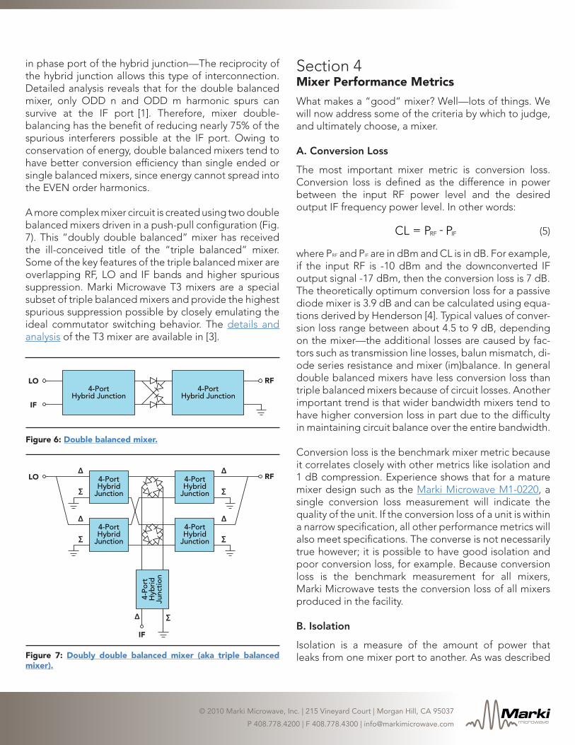
Markimicrowave
copy 2010 Marki Microwave Inc | 215 Vineyard Court | Morgan Hill CA 95037
P 4087784200 | F 4087784300 | infomarkimicrowavecom