mixing behaviour of miscible liquid-liquid multiphase flow ... · pdf filesystem generated in...
TRANSCRIPT
CHEMICAL ENGINEERING TRANSACTIONS
VOL. 56, 2017
A publication of
The Italian Association
of Chemical Engineering Online at www.aidic.it/cet
Guest Editors: Jiří Jaromír Klemeš, Peng Yen Liew, Wai Shin Ho, Jeng Shiun LimCopyright © 2017, AIDIC Servizi S.r.l., ISBN 978-88-95608-47-1; ISSN 2283-9216
Mixing Behaviour of Miscible Liquid-Liquid Multiphase Flow in Stirred Tank with Different Marine Propeller Installment by
Computational Fluid Dynamics Method Suci Madhaniaa, Tantular Nurtonob, Anugrah Budi Cahyanib, Carolinab, Yuswan Muharama, Sugeng Winardib, Widodo Wahyu Purwanto*,a a Department of Chemical Engineering, Universitas Indonesia, Depok, Indonesia b Department of Chemical Engineering, Institut Teknologi Sepuluh Nopember, Surabaya, Indonesia [email protected]
This paper presents a three-dimensional and transient computational fluid dynamics (CFD) simulation of the miscible liquid-liquid system (water-molasses) in a stirred tank operated in turbulence regime. The mixing process is crucial role when the viscosity and density of the solution are different, even though the solution mutually dissolved. There are two configurations used in the modelling. The first configuration is a conical-bottomed cylindrical tank equipped with a side-entry marine propeller and the second one is equipped with the top-entry marine propeller. The geometry of tank (D = 0.26 m and H = 0.363 m) and propeller (d = 0.033 m) are the same in both configurations. The transient calculations were conducted using the mixture model multiphase flow approach coupled with RANS (Standard k − ) turbulence model with time step is 0.01 s. A multiple refference frame approach was applied to modelling propeller motion. The mixing behaviour and the prediction of the moment of impeller and shaft are compared between top-entry and side-entry configuration. Some simulation results included the flow pattern recognition and distribution of molasses was discussed. The flow pattern in the top-entry configuration was indicating a stable double loop circulation. Whereas the flow patterns in side-entry configuration showing loop circulation around the marine propeller, some unstable and disordered flow pattern also formed around the tank wall. The variation of the flow pattern which happened showed the instability of the mixing process in side-entry configuration. There is a significant different mixing process produced from the side entering and top entering based on the distribution of molasses inside the tank. The result of CFD-simulation shows that the moment of impeller and shaft decrease for the side-entry configuration, and increase for top-entry configuration toward complete mixing.
1. Introduction
Mixing of the miscible liquid has relevant application in a variety of industrial operations in chemical processes. The much experimental research effort has devoted to describing and understand the mixing behaviour in stirred tank, but only few research works studied an experiment on the mixing of miscible liquids, e.g. was done by van de Vusse (1955) Experimentally mixing study has more time-consuming and expensive than computationally. The computational fluid dynamic is a technique to solve a mathematical model of fluid dynamic by the computer to capture detailed information on the hydrodynamics of the multiphase liquid-liquid miscible flow. Recently, limited work studied the CFD of the mixing of liquid-liquid miscible flow. The blending of liquids different density and viscosity in a static mixer (Montante et al., 2016). The mixing of water-ethanol in the T-shape microdevice (Orsi et al., 2013). The mixing behaviour of ethanol and glycerol in the stirred tank equipped with an anchor impeller using the Modified Algebraic Slip Mixture (MASM) multiphase model under laminar flow (Al-Qaessi and Abu-Farah, 2009). The homogenization of miscible liquid with different densities in a flat bottom cylindrical stirred tank equipped with a pitch blade turbine using the Lattice-Boltzmann method (LBM) without the use of modelling turbulence (Derksen, 2011).
DOI: 10.3303/CET1756177
Please cite this article as: Madhania S., Nurtono T., Cahyani A.B., Carolina, Muharam Y., Winardi S., Purwanto W.W., 2017, Mixing behaviour of miscible liquid-liquid multiphase flow in stirred tank with different marine propeller installment by computational fluid dynamics method, Chemical Engineering Transactions, 56, 1057-1062 DOI:10.3303/CET1756177
1057
Research on mixing inside stirred tank mostly related to top-entry impellers; little work has done on evaluating side-entry impellers. The experimental research to study the perform of the side-entry propeller in cylindrical storage tanks (Wesselingh, 1975). The homogenization of suspension by side entering agitator (Kipke and Klausdieter, 1984). Some researchers have conducted a CFD-simulation of immiscible liquid-liquid with different densities in a flat bottom cylindrical storage tank equipped with a side-entry marine propeller, i.e., simulation the mixing time (Rahimi and Parvareh, 2007). The numerical simulation to study the effect of the horizontal impeller on the large-scale bioethanol fermenter (Zhang et al., 2012). This work presents a three-dimensional and transient CFD approach to compare the mixing behaviour for a miscible liquid of water and molasses under turbulence regime in a stirred tank equipped with side-entry and top-entry marine propeller.
2. Computational fluid dynamics method
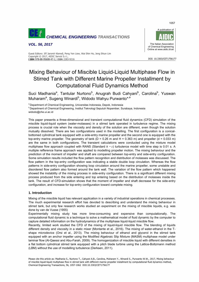
The tank system is a conical-bottomed cylindrical tank, of diameter 0.26 m and height 0.363 m without a baffle. The tank equipped with three blade B-series marine propeller with diameter 0.033 m. The geometry system generated in three dimensions by using Ansys Design Modeler software that showed in Figure 1 and Figure 2. In this study, the stirred tank was investigated through two different configurations. In the first configuration, the marine propeller is mounted on the side of the tank, while the second configuration the marine propeller is installed with top entering. The propeller modelled with a rotational speed, N = 2,000 rpm in both settings. In this study, water and molasses with a high difference of viscosity and density were set as the primary and secondary phase in liquid-liquid phase. The initial condition for both of the system defined as in the following:
1. The volume of the molasses fills the tank to a height of 0.13 m, and the amount of water fills the tank to the height from 0.13 to 0.363 m above molasses.
2. The water and molasses height defined the initial mass fraction of water/molasses in the liquid mixture in the tank.
Tank wall treated as the non-slip wall (no-slip condition), and friction is arising from the wall-fluid model with standard wall function. Propeller moving wall regarded as a non-slip condition. The shaft as absolute moving wall. Surface liquid treated as symmetry (zero normal gradients of all variables at the liquid surface). To define the boundary condition, the flow domain divided into two cylindrical, i.e. moving zone and stationary zone. Moving zone include the propeller, and the stationary zone is all domain without moving zone. The domain is divided into unstructured grids as listed in Table 1. The simulation results were analysed through the observation of the flow characteristics in plane observation and some sample points as shown in Figure 1 The moment of impeller and shaft motion was recorded for each of time step. The simulations were started from the fluid in all of the calculation domain at rest and calculated with 0.01 s as a time step.
Figure 1: The geometry and dimension (in m) of (1) the side-entry configuration and (2) the top-entry configuration.
1058

Table 1: Number of grids for side-entry and top-entry propeller instalment.
Configuration Number of grids Moving zone Stationary zone
Side-entry 103,601 393,610 Top-entry 113,601 395,507
Figure 2: Geometry of the marine propeller
Figure 3: Observation plane for both of the stirred tank configuration
In the present study, The simulation model is formulated for multiphase flow under turbulence regime (ANSYS-Fluent, 2016). The mixture model applies to model a multiphase flow where the phase is moving at different velocities, using the concept of slip velocities by solving the continuity equation, the momentum equation and the standard k-ε turbulence model for the mixture. A Multiple Reference Frames (MRF) model has implemented to the modelling impeller. This model is a steady-state approximation in which individual cell zones can be assigned different rotational and translational speeds. The model equations numerically solved by adopting the finite volume CFD code Ansys Fluent 17.1. The SIMPLE algorithm is used to solve couple pressure and velocity. The flow patterns of the liquid mixture with time can predict by drawing the vector plots of the velocity of the mix.
3. Results and discussions
Marine Propeller is an impeller that produces axial flow pattern. Figure 4 displays the flow pattern created by the side-entry configuration. Fluid flow caused by the axial impeller in the stirred tank forms one loop circulation. Fluid flow out towards the bottom of the tank towards the negative axis (down) then at the bottom of the tank, it deviates changing its direction moving upward toward the positive axis throughout the tank wall. Then the fluid flows radially entered negative axial direction (down) again towards the impeller and end the loop circulation. In fact, there are some irregular and unstable flow patterns that formed around the tank wall. Liquid stream at the bottom of the conical tank has greater speed than at the top of the conical tank. Figure 5 shows velocity vector magnitude in the form of plots in the field for systems for top-entry configuration. In a top-entry configuration, the fluid flow tends to create a stable double-loop circulations flow pattern. The flow pattern of water moving toward the negative axis (down) formed a pumping down circulation and produce a large shear stress between molasses-water. Molasses diffuses and lifted by circulation flow into the water rich region and begins the mixing process of molasses-water system. The flow pattern is influenced by several factors such as the rotational speed of the impeller, the geometry of the tank and the mounting position of the
1059

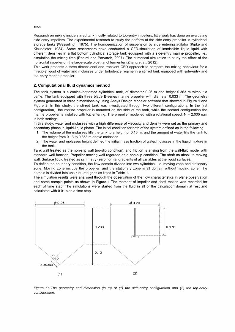
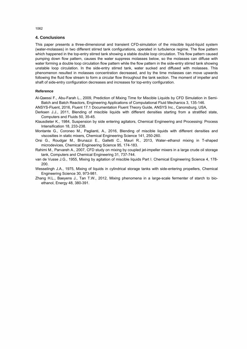
impeller and impeller type. This flow pattern is fascinating to study because of the presence of this variation in flow patterns, indicating instability in a mixing process. The contour of phase during the mixing process in the side-entry and top-entry configuration as shown in Figure 6 and Figure 7. Figure 6 shows that the greatest concentration still placed at the bottom of the conical tank. Then after the mixing process begins, water sucked and diffused with molasses. This phenomenon resulted in the molasses concentration decreased, and by the time molasses can moving upwards following the fluid flow stream to form a circular spread throughout the tank section. The concentration profile of molasses began to spread upward. In contrast to the side-entry configuration, the top-entry configuration that produced pumping down circulation below the impeller causes the water suppress molasses below, and the molasses diffuse upward and lifted by the double loop circulations as shown in Figure 7. In this study, the value of impeller and shaft moment for two configurations as depicted in Figure 8. The moment of the impeller and the shaft for side-entry configuration decreases as a function of time because the impeller mixed the fluid that the viscosity decreases. In another hand the viscosity of fluid around the impeller in top-entry configuration increases that caused the moment of impeller and shaft increases.
Figure 4: The flow pattern produced by the side-entry configuration at 70 s.
Figure 5: The flow pattern generated by the top-entry configuration at 70 s.
1060
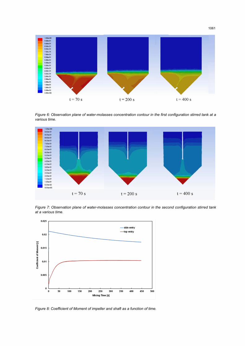
Figure 6: Observation plane of water-molasses concentration contour in the first configuration stirred tank at a various time.
Figure 7: Observation plane of water-molasses concentration contour in the second configuration stirred tank at a various time.
Figure 8: Coefficient of Moment of impeller and shaft as a function of time.
0
0,005
0,01
0,015
0,02
0,025
0 100 200 300 400 500
Mom
ent (
Nm
)
MIxing Time (s)
side entry
top entry
1061
4. Conclusions
This paper presents a three-dimensional and transient CFD-simulation of the miscible liquid-liquid system (water-molasses) in two different stirred tank configurations, operated in turbulence regime. The flow pattern which happened in the top-entry stirred tank showing a stable double loop circulation. This flow pattern caused pumping down flow pattern, causes the water suppress molasses below, so the molasses can diffuse with water forming a double loop circulation flow pattern while the flow pattern in the side-entry stirred tank showing unstable loop circulation. In the side-entry stirred tank, water sucked and diffused with molasses. This phenomenon resulted in molasses concentration decreased, and by the time molasses can move upwards following the fluid flow stream to form a circular flow throughout the tank section. The moment of impeller and shaft of side-entry configuration decreases and increases for top-entry configuration.
Reference
Al-Qaessi F., Abu-Farah L., 2009, Prediction of Mixing Time for Miscible Liquids by CFD Simulation in Semi-Batch and Batch Reactors, Engineering Applications of Computational Fluid Mechanics 3, 135-146.
ANSYS-Fluent, 2016, Fluent 17.1 Documentation Fluent Theory Guide, ANSYS Inc., Canonsburg, USA, Derksen J.J., 2011, Blending of miscible liquids with different densities starting from a stratified state,
Computers and Fluids 50, 35-45. Klausdieter K., 1984, Suspension by side entering agitators, Chemical Engineering and Processing: Process
Intensification 18, 233-238. Montante G., Coroneo M., Paglianti, A., 2016, Blending of miscible liquids with different densities and
viscosities in static mixers, Chemical Engineering Science 141, 250-260. Orsi G., Roudgar M., Brunazzi E., Galletti C., Mauri R., 2013, Water–ethanol mixing in T-shaped
microdevices, Chemical Engineering Science 95, 174-183. Rahimi M., Parvareh A., 2007, CFD study on mixing by coupled jet-impeller mixers in a large crude oil storage
tank, Computers and Chemical Engineering 31, 737-744. van de Vusse J.G., 1955, Mixing by agitation of miscible liquids Part I. Chemical Engineering Science 4, 178-
200. Wesselingh J.A., 1975, Mixing of liquids in cylindrical storage tanks with side-entering propellers, Chemical
Engineering Science 30, 973-981. Zhang H.L., Baeyens J., Tan T.W., 2012, Mixing phenomena in a large-scale fermenter of starch to bio-
ethanol, Energy 48, 380-391.
1062