mk-20 series owner’s manual, gas powered operating ... · operating instructions ... operating...
TRANSCRIPT

02.2017
MK-20 SERIESOWNER’S MANUAL,
OPERATING INSTRUCTIONS & PARTS LIST
www.mkdiamond.com
Caution: Read all safety and operating instructions before using this equipment. This owner’s manual MUST accompany the equipment at all times.
Revision 310
Manual Part# 156777
Gas Powered Concrete Saw
ModElS: MK-2013HSP GX390 Part # 156499 MK-2020HSP GX630 Part # 156498MK-2024HSP GX360 Part # 158777
MK-2013HE GX390 Part # 155714MK-2014K CH440 Part # 168798
MK-2013VSP V-Twin Part # 169949
MK-2024HSP GX360Part # 158777

2
INTRodUCTIoN
Congratulations on your purchase of a MK-20 Series. We are certain that you will be pleased with your purchase. MK Diamond takes pride in producing the finest construction power tools and diamond blades in the industry.
Operated correctly, your MK-20 Series should provide you with years of service. In order to help you, we have included this manual. This owners manual contains information necessary to operate and maintain your MK-20 Series safely and correctly. Please take the time to familiarize yourself with the MK-20 Series by reading and reviewing this manual.
Read and follow all safety, operating and maintenance instructions.
If you should have questions concerning your MK-20 Series, please feel free to call our friendly customer service department at: 800 421-5830
Regards,
MK Diamond
NoTE THIS INFoRMATIoN FoR FUTURE USE:ModEl NUMBER:
SERIAl NUMBER:
PURCHASE PlACE:
PURCHASE dATE:
NoTE: For your (1) one year warranty to be effective, complete the warranty card (including the Serial Number) and mail it in as soon as possible.
3
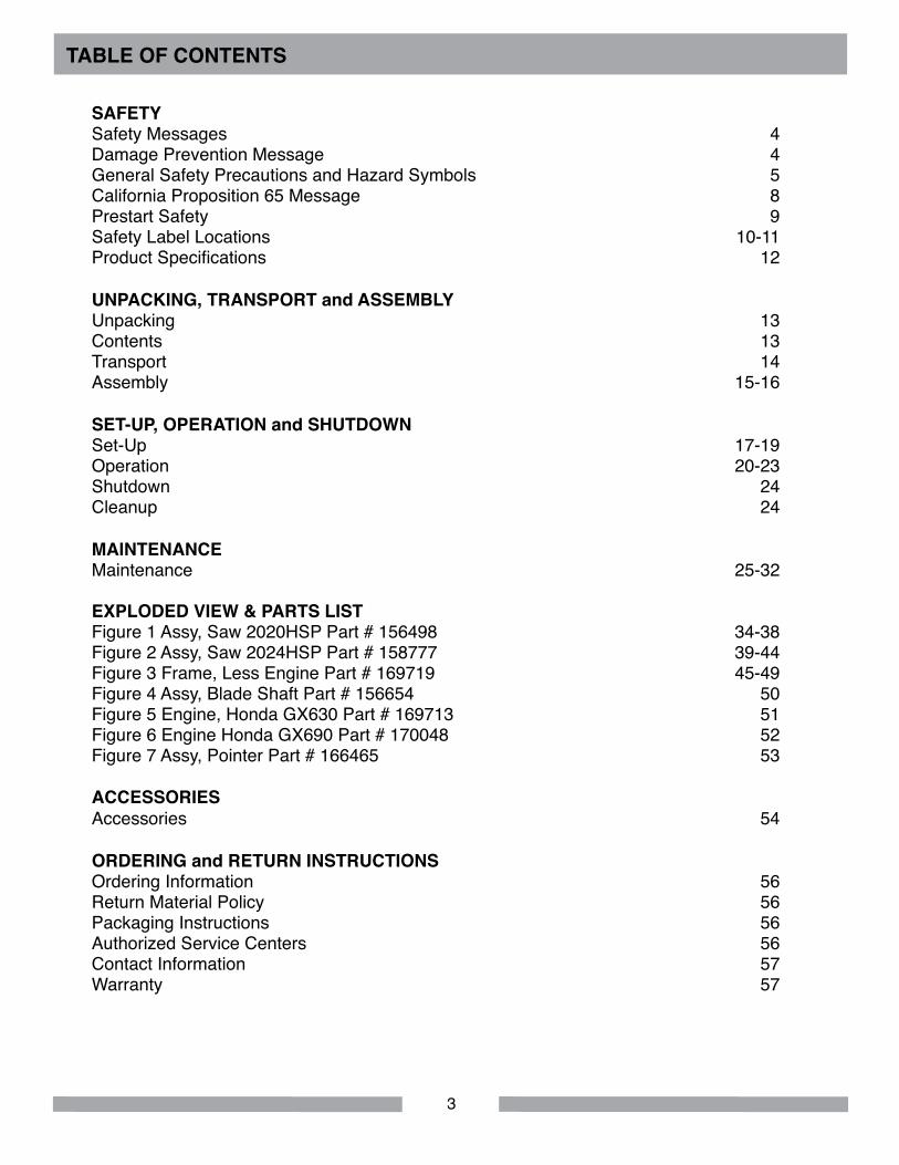
TABlE oF CoNTENTS
SAFETYSafety Messages 4 Damage Prevention Message 4 General Safety Precautions and Hazard Symbols 5 California Proposition 65 Message 8Prestart Safety 9 Safety Label Locations 10-11 Product Specifications 12
UNPACKING, TRANSPoRT and ASSEMBlY Unpacking 13 Contents 13 Transport 14 Assembly 15-16
SET-UP, oPERATIoN and SHUTdoWN Set-Up 17-19 Operation 20-23Shutdown 24 Cleanup 24
MAINTENANCE Maintenance 25-32
EXPlodEd VIEW & PARTS lIST Figure 1 Assy, Saw 2020HSP Part # 156498 34-38Figure 2 Assy, Saw 2024HSP Part # 158777 39-44Figure 3 Frame, Less Engine Part # 169719 45-49Figure 4 Assy, Blade Shaft Part # 156654 50Figure 5 Engine, Honda GX630 Part # 169713 51Figure 6 Engine Honda GX690 Part # 170048 52Figure 7 Assy, Pointer Part # 166465 53
ACCESSoRIESAccessories 54
oRdERING and RETURN INSTRUCTIoNS Ordering Information 56Return Material Policy 56 Packaging Instructions 56 Authorized Service Centers 56Contact Information 57Warranty 57

4
MK-20 SERIES SAFETY
Safety precautions should be followed at all times when operating this equipment. Failure to read and understand the Safety Precaution and Operating Instructions could result in injury to yourself and others.
This Operation Manual has been developed to provide complete instructions for the safe and efficient operation of the MK-20 Series. For additional instruction concerning engine operations and care refer to the engine manufacturers instructions.
Descriptions, illustrations, and photos are as accurate as possible at the time of publication. Photos may include optional equipment or accessories and may not show all models covered by this manual.
SAFETY MESSAGE / AlERT SYMBolS
A safety message alerts you to potential hazards that could hurt you or others. Each safety message is preceded by a safety alert symbol ( ) and one of three words: dANGER, WARNING, or CAUTIoN.
dANGER
You WIll be KIllEd or SERIoUSlY INJUREd if you do not follow directions.
WARNINGYou CAN be KIllEd or SERIoUSlY INJUREd if you do not follow directions.
CAUTIoN
You CAN be INJUREd if you do not follow directions. It may also be used to alert against unsafe practices.
NoTICEYou can cause PRoPERTY dAMAGE to your machine if you don’t follow directions.
Each message tells you what the hazard is, what can happen, and what you can do to avoid or reduce injury. Other important messages are preceded by the word NoTICE.
The safety labels should be periodically inspected and cleaned by the user to maintain good legibility at a safe viewing distance. If the label is worn, damaged or illegible, it should be replaced. Contact MK Diamond or your dealer for replacement.
Before using this saw, ensure that the person operating the equipment has read and understands all instructions in this manual.
dAMAGE PREVENTIoN ANd INFoRMATIoN MESSAGES
A Damage Prevention Message is to inform the user of important information and/or instructions that could lead to equipment or other property damage if not followed. Information messages convey information that pertains to the equipment being used. Each message will be preceded by the word note, as in the example below.
NoTE: Equipment and/or property damage may result if these instructions are not followed.

5
MK-20 SERIES SAFETY
EXPloSIVE FUEl! Gasoline is extremely flammable, its vapors can explode if ignited; store only in approved containers, in well-ventilated, unoccupied buildings and away from sparks or flames. Do not fill the fuel tank while the engine is running or hot. Spilled fuel could ignite if it contacts hot parts or sparks from ignition. Do not start the engine near spilled fuel. Never use gasoline as a cleaning agent. Never operate the machine in an explosive atmosphere.
In order to prevent injury, keep guards in place and in working order at all times.
KEEP GUARdS IN PlACE
SAFETY PRECAUTIoNS
GENERAl SAFETY PRECAUTIoNS ANd HAZARd SYMBolS
((
))ENGINE oVER-SPEEd
Never tamper with the governor components or settings to increase the maximum speed of the machine. Severe personal injury and/or equipment damage could result if the equip-ment is operated speeds above design maximum.
lETHAl EXHAUST GASESEngine exhaust gasses contain poisonous carbon monoxide, an odorless colorless gas that can cause death if inhaled. Avoid inhaling exhaust fumes, and never run the engine in a closed building or confined area.
In order to prevent injury, the following safety precautions and symbols should be followed at all times!
GENERAl SAFETY
do NoT operate or service this equipment before reading this entire manual.
This equipment should not be operated by persons under 18 years of age.
NEVER operate this equipment when not feeling well due to fatigue, illness or taking medicine.
NEVER operate this equipment under the influence of drugs or alcohol.
Whenever necessary, replace nameplate, operation and safety decals when they become difficult to read.
AlWAYS store equipment properly when it is not being used. Equipment should be stored in a clean, dry location out of the reach of children.

6
MK-20 SERIES SAFETY
KEEP CHIldREN AWAYAll visitors and children should be kept a safe distance from work area.
MAKE WoRKSHoP KId PRooFMake the workshops kid proof by using padlocks, master switches or by removing starter keys.
REMoVE AdJUSTING KEYS ANd WRENCHESForm a habit of checking to see that keys and adjusting wrenches are removed from the power tool before it is turned on.
KEEP WoRK AREA ClEAN Cluttered work areas and benches invite accidents.
do NoT USE IN dANGERoUS ENVIRoNMENTS Do not operate equipment in dangerous environments. Always keep the work area well lighted.
AlWAYS USE SAFETY GlASSESSafety glasses should always be worn when working around power tools. Everyday eye-glasses only have impact resistant lenses and may not prevent eye injury; they are NOT safety glasses.
AlWAYS USE RESPIRAToRY PRoTECTIoN Exhaust gases may be harmful if inhaled. Do not operate gas-powered equipment in enclosed spaces. Respiratory protection should be worn when operating gas powered equipment.
AlWAYS USE HEARING PRoTECTIoNTo reduce the possibility of hearing loss, always use hearing protection when operating equipment.
RoTATING oR MoVING PARTS
Keep hands, feet, hair, and clothing away from all moving parts to prevent injury. Never operate a power tool with shrouds or guards removed.
HoT PARTS Engine components can become extremely hot from operation. To prevent severe burns, do not touch these areas while the engine is running, or immediately after it is turned off. Never operate the engine with heat shields removed.
on
ACCIdENTAl STARTSBefore starting the engine, be sure the ON/OFF switch is in the “OFF” position to prevent accidental starting. Place the ON/OFF switch in the OFF position before performing any service operation.
7
do NoT oVERREACH Keep proper footing and balance at all times by not overreaching.
MAINTAIN ToolS WITH CAREKeep tools sharp and clean for the best and safest performance. Always follow maintenance instruc-tions for lubricating and when changing accessories.
SHUTdoWN ToolThe saw should always be shutdown before servicing or when changing accessories such as blades, bits, cutters, etc...
USE RECoMMENdEd ACCESSoRIESConsult the owner’s manual for recommended accessories. Using improper accessories may in-crease the risk of personal or by-stander injury.
NEVER STANd oN THE ToolSerious injury could occur if a power tool is tipped, or if a cutting tool is unintentionally contacted.
do NoT FoRCE THE ToolA power tool will do a job better and safer operating at the rate for which it was designed.
USE THE RIGHT ToolDo not force a tool or an attachment, to do a job that it was not designed to do.
WEAR PRoPER APPARElDo not wear loose clothing, gloves, neckties, rings, bracelets, or other jewelry that may be caught in moving parts. Nonslip footwear is recommended. Wear protective hair covering to contain long hair.
SECURE WoRKClamps or a vise should be used to hold work whenever practical. Keeping your hands free to oper-ate a power tool is safer.
MK-20 SERIES SAFETY
NEVER lEAVE Tool RUNNING UNATTENdEd – TURN PoWER oFFDo not leave a tool until it comes to a complete stop. Always turn a power tool OFF when leaving the work area, or, when a cut is finished.
CHECK FoR dAMAGEd PARTS Before using a power tool, check for damaged parts. A guard or any other part that is damaged should be carefully checked to determine if it would operate properly and perform its intended function safety. Always check moving parts for proper alignment or binding. Check for broken parts, mount-ings and all other conditions that may affect the operation of the power tool. A guard or any damaged part should be properly repaired or replaced.
dIRECTIoN oF FEEdAlways feed work into a blade or cutter against the direction of rotation. A blade or cutter should always be installed such that rotation is in the direction of the arrow imprinted on the side of the blade or cutter.

8
MK-20 SERIES SAFETY
Sawing, grinding and drilling generate dust. Excessive airborne particles may cause irritation to eyes, skin and respiratory tract. To avoid breathing impairment, always employ dust controls and protection suitable to the material being sawed or drilled; See OSHA (29 CFR Part 1910.1200).
WARNING
CAlIFoRNIA PRoPoSITIoN 65 MESSAGESome dust created by power sanding, sawing, grinding, drilling, and other construction activities con-tain chemicals known (to the State of California) to cause cancer, birth defects or other reproductive harm. Some examples of these chemicals are:
• Lead, from lead-based paints • Crystalline silica from bricks, cement and other masonry products • Arsenic and chromium, from chemically treated lumber
For further information, consult the following sources: http://www.osha.gov/dsg/topics/silicacrystalline/index.html http://www.cdc.gov/niosh/docs/96-112/ http://oehha.ca.gov/prop65/law/P65law72003.html http://www.dir.ca.gov/Title8/sub4.html
Your risk from these exposures varies depending on how often you do this type of work. To reduce your exposure to these chemicals, work in a well-ventilated area, and work with approved safety equipment, such as dust masks that are specially designed to filter out microscopic particles. Where use of a dust extraction device is possible, it should be used. To achieve a high level of dust collec-tion, use an industrial HEPA vacuum cleaner. Observe OSHA 29 CFR part 1926.57 and 1926.103.
SIlICA dUST WARNINGGrinding/cutting/drilling of masonry, concrete, metal and other materials with silica in their composition may give off dust or mists containing crystalline silica. Silica is a basic component of sand, quartz, brick clay, granite and numerous other minerals and rocks. Repeated and/or substantial inhalation of airborne crystalline silica can cause serious or fatal respiratory diseases, including silicosis. In ad-dition, California and some other authorities have listed respirable crystalline silica as a substance known to cause cancer. When cutting such materials, always follow respiratory precautions.
Use appropriate NIOSH-approved respiratory protection where dust hazard may occur. Paper masks or surgical masks without a NIOSH approval number are not recommended because they do little to protect the worker. For more information about respirator programs, including what respirators have received NIOSH approval as safe and effective, please visit the NIOSH website at: http://www.cdc.gov/niosh/topics/respirators
Observe OSHA regulations for respirator use (29 C.F.R.§1910.134). Visit http://www.osha.gov for more information.
ON
((
))

9
NoTES

10
oPERATIoN & SAFETY dECAlS
Part # 164202
A
B
D
F
C
E
G
I
J
H K
L
M
N
WARNING•Thisequipmentmayproducedustormistscontaining crystallinesilica.•Silicaisabasiccomponentofmasonry,concrete,and othermaterials.•Repeatedand/orsubstantialinhalationcancause seriousorfatalrespiratorydiseasesincludingsilicosis.•RespirablecrystallinesilicaislistedbyCaliforniaand otherauthoritiesasasubstanceknowntocausecancer.•Employdustcontrolsandprotectionper OSHA/NIOSH/MSHA.
!
Part # 155587 (3)
CAUTION
DO NOToperate without guards in place.
!
Part # 155588
Part # 154398
WARNINGIn the event of blade failure, replace blade guard immediately.
!
DO NOT operate this equipment before reading the owner’s manual.
WARNING!
Part # 155038
SERVICE OR WARRANTY
FOR INFORMATION ON
PLEASE CALL1-800-474-5594
Part # 170480Part # 155585
CAUTIONKeep hands and feet clear.
!
Part # 154399
NOTICEOvertensioning of belts will result in premature crank and/or bearing failure.
!
Part # 155582
Part # 156749
Part # 155579
CAUTION
DO NOTtouch hot surface.
!
Part # 155578
CAUTIONAccidental start hazard. Disconnect spark plug prior to servicing.
!
Part # 155580Part # 155581
WARNINGWhen refueling stop engine and allow to cool. DO NOT overfill tank.
!DANGER
The exhaust from this product con-tains chemicals known to the State of California to cause cancer, birth defects or other reproductive harm.
!
DANGERLethal exhaust gases. Use only in well ventilated areas. DO NOT use indoors.
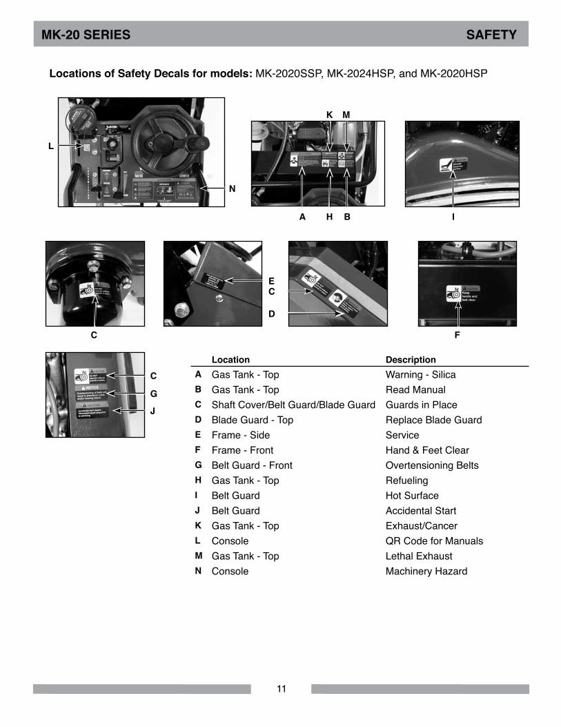
location descriptionA Gas Tank - Top Warning - SilicaB Frame - Side Read ManualC Shaft Cover/Belt Guard/Blade Guard Guards in Placed Blade Guard - Top Replace Blade GuardE Console ServiceF Frame - Front Hand & Feet ClearG Belt Guard - Front Overtensioning BeltsH Gas Tank - Side RefuelingI Belt Guard Hot SurfaceJ Belt Guard Accidental StartK Gas Tank - Side Exhaust/Cancerl Console QR Code for ManualsM Gas Tank - Side Lethal ExhaustN Console Machinery Hazard
MK-20 SERIES SAFETY
The MK-20 Series Concrete Saw is equipped with a number of safety decals. These decals are pro-vided for operator safety and maintenance information. Should any of these operation or safety de-cals become unreadable, replacements can be obtained by calling (800) 262-1575.
CGJ
l
E
I
F
B C M K N
H
d
C
A
location of Safety decals for models: MK-2013HE, MK-2013HSP, MK-2013SE, MK-2013SSP, MK-2013VSP, and MK-2014K
11
location descriptionA Gas Tank - Top Warning - SilicaB Gas Tank - Top Read ManualC Shaft Cover/Belt Guard/Blade Guard Guards in Placed Blade Guard - Top Replace Blade GuardE Frame - Side ServiceF Frame - Front Hand & Feet ClearG Belt Guard - Front Overtensioning BeltsH Gas Tank - Top RefuelingI Belt Guard Hot SurfaceJ Belt Guard Accidental StartK Gas Tank - Top Exhaust/Cancerl Console QR Code for ManualsM Gas Tank - Top Lethal ExhaustN Console Machinery Hazard
MK-20 SERIES SAFETY
N
K M
BH IA
F
E
C
G
J
C
d
C
l
locations of Safety decals for models: MK-2020SSP, MK-2024HSP, and MK-2020HSP
12
MK-20 SERIES PRodUCT SPECIFICATIoN
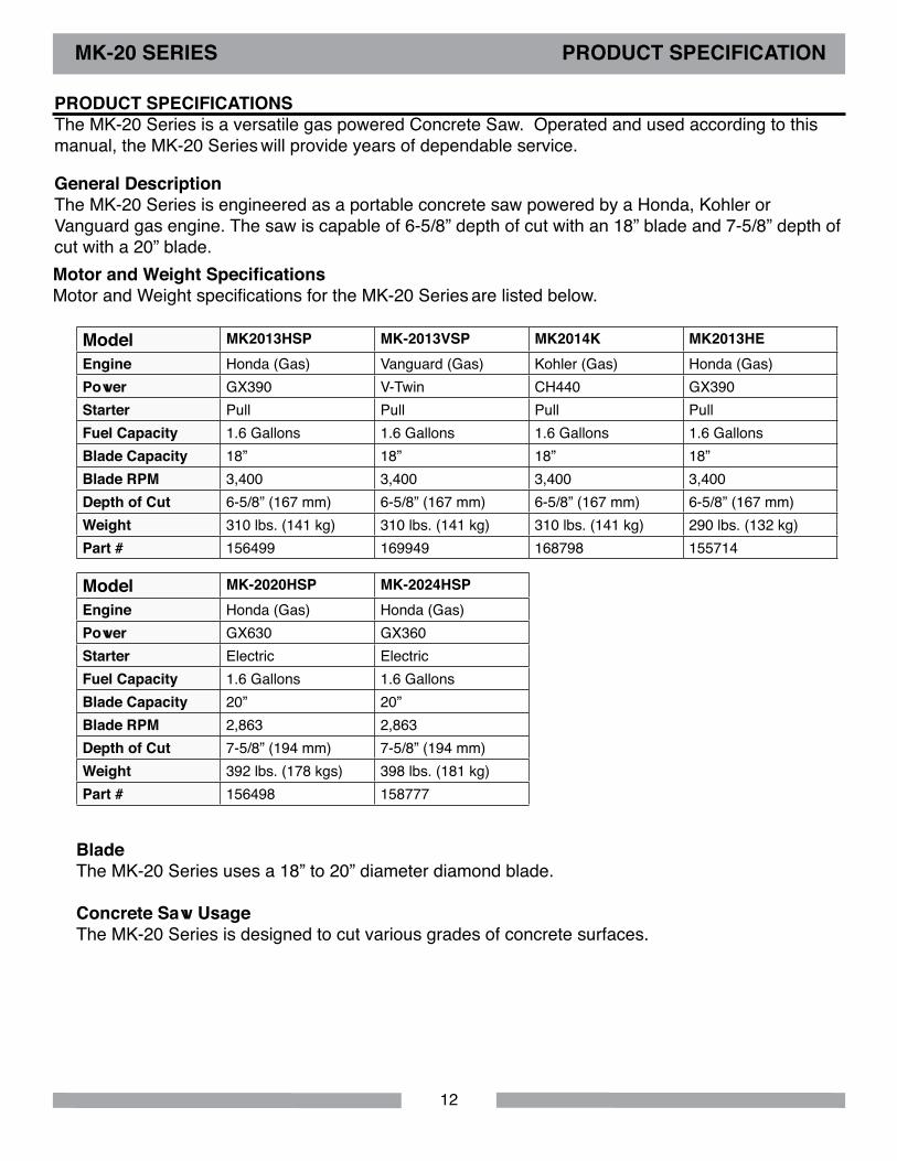
BladeThe MK-20 Series uses a 18” to 20” diameter diamond blade. Concrete Saw UsageThe MK-20 Series is designed to cut various grades of concrete surfaces.
PRodUCT SPECIFICATIoNS The MK-20 Series is a versatile gas powered Concrete Saw. Operated and used according to this manual, the MK-20 Series will provide years of dependable service.
General descriptionThe MK-20 Series is engineered as a portable concrete saw powered by a Honda, Kohler or Vanguard gas engine. The saw is capable of 6-5/8” depth of cut with an 18” blade and 7-5/8” depth of cut with a 20” blade.
Model MK2013HSP MK-2013VSP MK2014K MK2013HEEngine Honda (Gas) Vanguard (Gas) Kohler (Gas) Honda (Gas)Power GX390 V-Twin CH440 GX390Starter Pull Pull Pull PullFuel Capacity 1.6 Gallons 1.6 Gallons 1.6 Gallons 1.6 GallonsBlade Capacity 18” 18” 18” 18”Blade RPM 3,400 3,400 3,400 3,400depth of Cut 6-5/8” (167 mm) 6-5/8” (167 mm) 6-5/8” (167 mm) 6-5/8” (167 mm)Weight 310 lbs. (141 kg) 310 lbs. (141 kg) 310 lbs. (141 kg) 290 lbs. (132 kg)Part # 156499 169949 168798 155714
Model MK-2020HSP MK-2024HSPEngine Honda (Gas) Honda (Gas)Power GX630 GX360Starter Electric ElectricFuel Capacity 1.6 Gallons 1.6 GallonsBlade Capacity 20” 20”Blade RPM 2,863 2,863depth of Cut 7-5/8” (194 mm) 7-5/8” (194 mm)Weight 392 lbs. (178 kgs) 398 lbs. (181 kg)Part # 156498 158777
Motor and Weight SpecificationsMotor and Weight specifications for the MK-20 Series are listed below.
13
UNPACKING
MK-20 SeriesSaw
1 Blade NutWrench
Engine Manual WarrantyCard
MK-20 SeriesOwner’s Manual
PointerHandlebarBolts and Washers
Handlebar
MK-20 SERIES UNPACKING
03.2012
MK-20 SERIESOWNER’S MANUAL &
OPERATING INSTRUCTIONS
www.mkdiamond.com
Caution: Read all safety and operating instructions before using this equipment. This owner’s manual MUST accompany the equipment at all times.
Revision 201
Manual Part# 156777
Gas Powered Concrete Saw
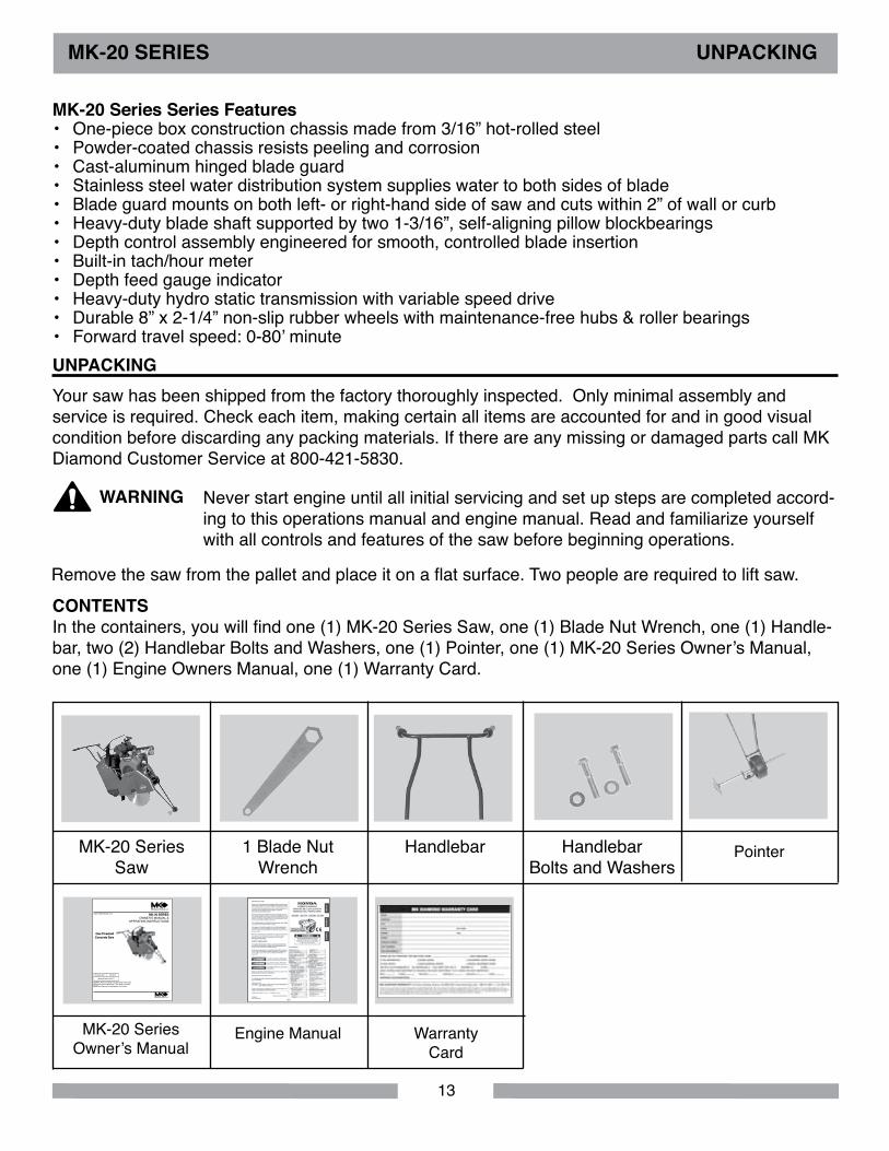
Your saw has been shipped from the factory thoroughly inspected. Only minimal assembly and service is required. Check each item, making certain all items are accounted for and in good visual condition before discarding any packing materials. If there are any missing or damaged parts call MK Diamond Customer Service at 800-421-5830.
CoNTENTS In the containers, you will find one (1) MK-20 Series Saw, one (1) Blade Nut Wrench, one (1) Handle-bar, two (2) Handlebar Bolts and Washers, one (1) Pointer, one (1) MK-20 Series Owner’s Manual, one (1) Engine Owners Manual, one (1) Warranty Card.
WARNING Never start engine until all initial servicing and set up steps are completed accord-ing to this operations manual and engine manual. Read and familiarize yourself with all controls and features of the saw before beginning operations.
Remove the saw from the pallet and place it on a flat surface. Two people are required to lift saw.
MK-20 Series Series Features• One-piece box construction chassis made from 3/16” hot-rolled steel• Powder-coated chassis resists peeling and corrosion• Cast-aluminum hinged blade guard• Stainless steel water distribution system supplies water to both sides of blade• Blade guard mounts on both left- or right-hand side of saw and cuts within 2” of wall or curb • Heavy-duty blade shaft supported by two 1-3/16”, self-aligning pillow blockbearings• Depth control assembly engineered for smooth, controlled blade insertion• Built-in tach/hour meter• Depth feed gauge indicator• Heavy-duty hydro static transmission with variable speed drive• Durable 8” x 2-1/4” non-slip rubber wheels with maintenance-free hubs & roller bearings• Forward travel speed: 0-80’ minute

14
1
2
3
4 56
TRANSPoRT
dESCRIPTIoN oF CoNTRolS
MK-20 SERIES TRANSPoRT
CAUTIoN 1. The MK-20 Series weighs approximately two hundred and thirty-five (235 pounds), use care when transporting.
2. Two people are required to lift and transport the MK-20 Series.
1. The Depth Control Wheel raises the blade when rotated clockwise, and lowers the blade when rotated counterclockwise. 2. The keyed ignition switch turns clockwise to the on and start positions. The engine turns over with the switch in the start position. Release the key after the engine starts.3. When the engine is running, the Tach/Hour Meter display will indicate the engines RPM. When the engine is shut off, the display will switch to run time, initially in minutes, and then switching to hours after the first hour of operation.4. The Transmission Speed Lever moves the saw forward by pushing the lever away from the operator and moves the saw in reverse by pulling the lever toward the operator. Always place this control in central neutral position before using the engage/disengage lever or starting or stopping the engine.5. The Throttle control increases engine rpm from slow (idle) at the bottom, to fast (full rpm) at the top.6. Depth Gauge should be adjusted to zero when setting up the saw.7. Use water hose bibb for wetting cutting. After connecting hose, turn on the water at the source and use Water Control Lever to control flow of water to the blade. Be sure that both sides of the blade are getting adequate flow of water.8. Water Control Lever is off in the vertical position and fully on in the horizontal position. It may be placed at in between settings to regulate the water flow.9. The Transmission Engage/Disengage Lever is engaged in the full down position.10. The Choke is located on the back panel for convenient cold starting.
7
8
9
10
15
MK-20 SERIES ASSEMBlY
FIllING oIl RESERVoIR
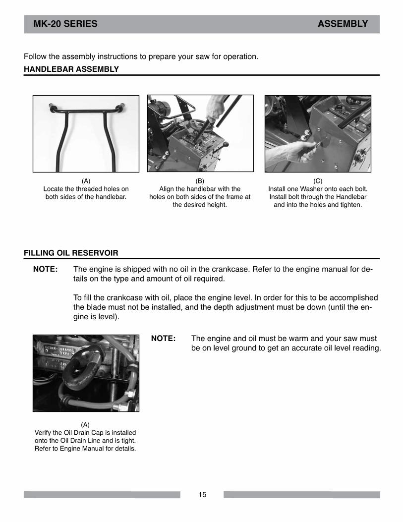
(A)Verify the Oil Drain Cap is installed onto the Oil Drain Line and is tight. Refer to Engine Manual for details.
(C)Install one Washer onto each bolt. Install bolt through the Handlebar
and into the holes and tighten.
Follow the assembly instructions to prepare your saw for operation.
(A)Locate the threaded holes on both sides of the handlebar.
(B)Align the handlebar with the
holes on both sides of the frame at the desired height.
HANdlEBAR ASSEMBlY
The engine is shipped with no oil in the crankcase. Refer to the engine manual for de-tails on the type and amount of oil required.
To fill the crankcase with oil, place the engine level. In order for this to be accomplished the blade must not be installed, and the depth adjustment must be down (until the en-gine is level).
The engine and oil must be warm and your saw must be on level ground to get an accurate oil level reading.
NoTE:
NoTE:

16
(A)Remove the front tower panel to ob-tain access to the battery terminals.
(A)Check the oil level on the expansion tank to ensure that the transmission
has adequate fluid.
(B)Connect the positive (+) battery
cable to the positive battery terminal. Connect the negative battery cable
to the negative terminal. Tighten the cap screws and nuts securely to assure proper electrical contact.
Replace panel.
MK-20 SERIES ASSEMBlY
BATTERY PREPARATIoN
HYdRo-STATIC TRANSMISSIoN
The 12 volt battery is shipped wet and charged. Connect the battery leads according to the following steps to ensure that power is provided to the engines electric starter.
The Hydro-Static Transmission is factory filled with fluid having a viscosity equivalent to SAE 20 W 20.
Do not overfill the expansion tank. Notice that the full level line is near the bottom of the expansion tank. Over filling will result in rupturing the seals on the hydromatic transmission and subsequent mechanical damage.
When tightening the positive (+) battery cable end, do not contact the nega-tive (-) battery terminal with the wrench or other metallic objects. This could cause an electrical short and electrical sparking or an explosion of the battery. Be careful not to connect the battery in reverse polarity, as this will short circuit the battery charging system causing the fuse on the engine to become dam-aged, and also possibly resulting in an explosion of the battery.
NoTICE
WARNING

17
MK-20 SERIES ASSEMBlY
1. When installing the blade retaining-bolt, ensure the threads of the bolt are aligned with the threads of the drive shaft so as not to “cross-thread” the bolt.2. When installing the blade ensure that the blade shaft and flanges are free from dirt and all foreign material before mounting blade on the blade shaft. Tightening a blade against an uneven surface can cause fracture or cause the blade to run out of alignment.3. Blade shaft threads are left-handed on the right side of the saw and right-hand on the left of the saw.
(A)Open the Blade Guard Cover.
Locate the Blade Shaft Nut and the Outer Flange.
NoTE:dIAMoNd BlAdE INSTAllATIoN
(B)Loosen the Blade Shaft Nut while holding the Shaft Wrench steady.
(F)Install the Blade Shaft Nut.
(C)Remove the Blade Nut and Outer
Flange.
(D)Install the Diamond Blade onto the Blade Shaft and Drive Pin. Ensure directional arrow on the blade indi-cates proper rotational direction.
(G)Tighten Blade Shaft Nut holding
the Blade Shaft steady. Lower and close Blade Guard.
(E)Install the Outer Flange. Verify the drive pin is seated; it must project
through the hole in the blade and into the flange.
WARNING Do not operate the saw without the proper Blade Guard covering. Ensure that the blade exposure does not exceed 180 degrees during operation.
Raise the blade as high as possible when ma-neuvering so that the blade will not strike the pavement. The blade is spinning whenever the saw is running.
NoTE:
do NoT use woodcutting, or carbide blades on this machine! Use oNlY Diamond blades on machine.
18
FIllING FUEl TANK
MK-20 SERIES SET-UP
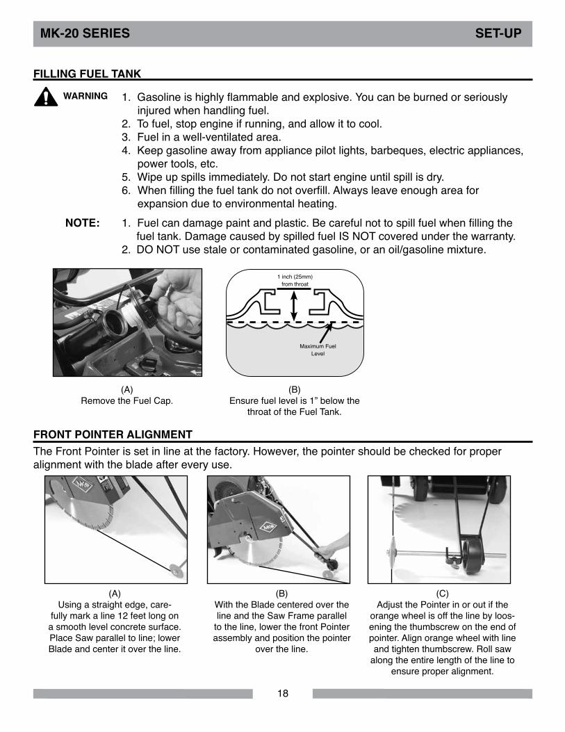
WARNING 1. Gasoline is highly flammable and explosive. You can be burned or seriously injured when handling fuel.2. To fuel, stop engine if running, and allow it to cool.3. Fuel in a well-ventilated area.4. Keep gasoline away from appliance pilot lights, barbeques, electric appliances, power tools, etc.5. Wipe up spills immediately. Do not start engine until spill is dry.6. When filling the fuel tank do not overfill. Always leave enough area for expansion due to environmental heating.1. Fuel can damage paint and plastic. Be careful not to spill fuel when filling the fuel tank. Damage caused by spilled fuel IS NOT covered under the warranty.2. DO NOT use stale or contaminated gasoline, or an oil/gasoline mixture.
NoTE:
(A)Remove the Fuel Cap.
(B)Ensure fuel level is 1” below the
throat of the Fuel Tank.
1 inch (25mm) from throat
Maximum Fuel Level
FRoNT PoINTER AlIGNMENTThe Front Pointer is set in line at the factory. However, the pointer should be checked for proper alignment with the blade after every use.
(A)Using a straight edge, care-
fully mark a line 12 feet long on a smooth level concrete surface. Place Saw parallel to line; lower Blade and center it over the line.
(B)With the Blade centered over the line and the Saw Frame parallel
to the line, lower the front Pointer assembly and position the pointer
over the line.
(C)Adjust the Pointer in or out if the
orange wheel is off the line by loos-ening the thumbscrew on the end of pointer. Align orange wheel with line and tighten thumbscrew. Roll saw
along the entire length of the line to ensure proper alignment.
19
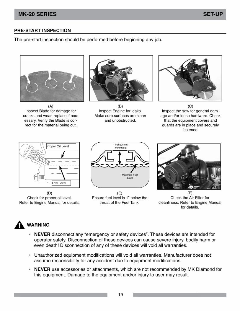
(D)Check for proper oil level.
Refer to Engine Manual for details.
Low Level
Proper Oil Level
(F)Check the Air Filter for
cleanliness. Refer to Engine Manual for details.
MK-20 SERIES SET-UP
(E)Ensure fuel level is 1” below the
throat of the Fuel Tank.
1 inch (25mm) from throat
Maximum Fuel Level
The pre-start inspection should be performed before beginning any job.
PRE-START INSPECTIoN
(A)Inspect Blade for damage for
cracks and wear, replace if nec-essary. Verify the Blade is cor-rect for the material being cut.
(C)Inspect the saw for general dam-
age and/or loose hardware. Check that the equipment covers and
guards are in place and securely fastened.
(B)Inspect Engine for leaks.
Make sure surfaces are clean and unobstructed.
• NEVER disconnect any “emergency or safety devices”. These devices are intended for operator safety. Disconnection of these devices can cause severe injury, bodily harm or even death! Disconnection of any of these devices will void all warranties.
• Unauthorized equipment modifications will void all warranties. Manufacturer does not assume responsibility for any accident due to equipment modifications.
• NEVER use accessories or attachments, which are not recommended by MK Diamond for this equipment. Damage to the equipment and/or injury to user may result.
WARNING
20
MK-20 SERIES SET-UP
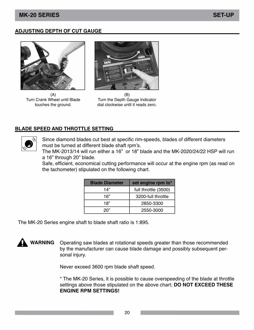
AdJUSTING dEPTH oF CUT GAUGE
BlAdE SPEEd ANd THRoTTlE SETTING
(A)Turn Crank Wheel until Blade
touches the ground.
(B)Turn the Depth Gauge Indicator dial clockwise until it reads zero.
Operating saw blades at rotational speeds greater than those recommended by the manufacturer can cause blade damage and possibly subsequent per-sonal injury.
Never exceed 3600 rpm blade shaft speed.
* The MK-20 Series, it is possible to cause overspeeding of the blade at throttle settings above those stipulated on the above chart; do NoT EXCEEd THESE ENGINE RPM SETTINGS!
WARNING
((
)) Since diamond blades cut best at specific rim-speeds, blades of different diameters must be turned at different blade shaft rpm’s.The MK-2013/14 will run either a 16” or 18” blade and the MK-2020/24/22 HSP will run a 16” through 20” blade.Safe, efficient, economical cutting performance will occur at the engine rpm (as read on the tachometer) stipulated on the following chart.
The MK-20 Series engine shaft to blade shaft ratio is 1:895.
Blade diameter set engine rpm to*14” full throttle (3500)16” 3200-full throttle18” 2850-330020” 2550-3000
21
do NoT crank engine for more than 30 seconds at a time. If engine fails to start, wait about 2 minutes between cranking periods to prevent starter from overheating.
NoTICE
Read the engine instructions manual before starting saw.NoTICE
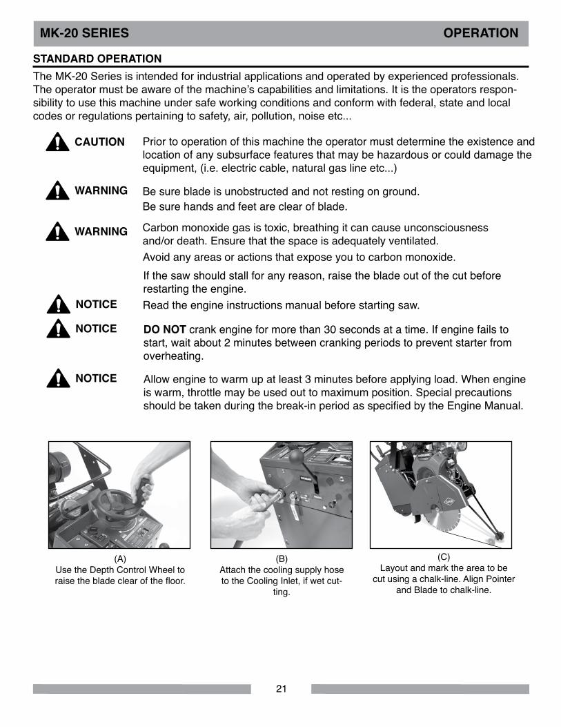
MK-20 SERIES oPERATIoN
STANdARd oPERATIoNThe MK-20 Series is intended for industrial applications and operated by experienced professionals. The operator must be aware of the machine’s capabilities and limitations. It is the operators respon-sibility to use this machine under safe working conditions and conform with federal, state and local codes or regulations pertaining to safety, air, pollution, noise etc...
(A)Use the Depth Control Wheel to raise the blade clear of the floor.
(B)Attach the cooling supply hose to the Cooling Inlet, if wet cut-
ting.
(C)Layout and mark the area to be
cut using a chalk-line. Align Pointer and Blade to chalk-line.
Prior to operation of this machine the operator must determine the existence and location of any subsurface features that may be hazardous or could damage the equipment, (i.e. electric cable, natural gas line etc...)
Be sure blade is unobstructed and not resting on ground.Be sure hands and feet are clear of blade.
CAUTIoN
WARNING
Carbon monoxide gas is toxic, breathing it can cause unconsciousness and/or death. Ensure that the space is adequately ventilated.
WARNING
Allow engine to warm up at least 3 minutes before applying load. When engine is warm, throttle may be used out to maximum position. Special precautions should be taken during the break-in period as specified by the Engine Manual.
NoTICE
Avoid any areas or actions that expose you to carbon monoxide.If the saw should stall for any reason, raise the blade out of the cut before restarting the engine.
22
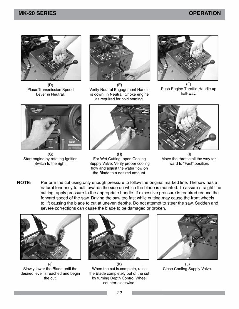
(K)When the cut is complete, raise
the Blade completely out of the cut by turning Depth Control Wheel
counter-clockwise.
MK-20 SERIES oPERATIoN
(L)Close Cooling Supply Valve.
Perform the cut using only enough pressure to follow the original marked line. The saw has a natural tendency to pull towards the side on which the blade is mounted. To assure straight line cutting, apply pressure to the appropriate handle. If excessive pressure is required reduce the forward speed of the saw. Driving the saw too fast while cutting may cause the front wheels to lift causing the blade to cut at uneven depths. Do not attempt to steer the saw. Sudden and severe corrections can cause the blade to be damaged or broken.
NoTE:
(J)Slowly lower the Blade until the
desired level is reached and begin the cut.
(H)For Wet Cutting, open Cooling
Supply Valve. Verify proper cooling flow and adjust the water flow on the Blade to a desired amount.
(G)Start engine by rotating Ignition
Switch to the right.
(I)Move the throttle all the way for-
ward to “Fast” position.
(D)Place Transmission Speed
Lever in Neutral.
(E)Verify Neutral Engagement Handle is down, in Neutral. Choke engine
as required for cold starting.
(F)Push Engine Throttle Handle up
half-way.
23
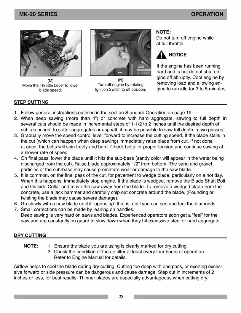
(M)Move the Throttle Lever to lower
blade speed.
(N)Turn off engine by rotating
Ignition Switch to off position.
dRY CUTTING
STEP CUTTING
MK-20 SERIES oPERATIoN
1. Ensure the blade you are using is clearly marked for dry cutting.2. Check the condition of the air filter at least every four hours of operation. Refer to Engine Manual for details.
Airflow helps to cool the blade during dry cutting. Cutting too deep with one pass, or exerting exces-sive forward or side pressure can be dangerous and cause damage. Step cut in increments of 2 inches or less, for best results. Thinner blades are especially advantageous when cutting dry.
NoTE:
If the engine has been running hard and is hot do not shut en-gine off abruptly. Cool engine by removing load and allowing en-gine to run idle for 3 to 5 minutes.
Do not turn off engine while at full throttle.
NoTICE
NoTE:
1. Follow general instructions outlined in the section Standard Operation on page 19. 2. When deep sawing (more than 4”) or concrete with hard aggregate, sawing to full depth in several cuts should be made in incremental steps of 1-1/2 to 2 inches until the desired depth of cut is reached. In softer aggregates or asphalt, it may be possible to saw full depth in two passes.3. Gradually move the speed control lever forward to increase the cutting speed. If the blade stalls in the cut (which can happen when deep sawing) immediately raise blade from cut. If not done at once, the belts will spin freely and burn. Check belts for proper tension and continue sawing at a slower rate of speed.4. On final pass, lower the blade until it hits the sub-base (sandy color will appear in the water being discharged from the cut). Raise blade approximately 1/2” from bottom. The sand and gravel particles of the sub-base may cause premature wear or damage to the saw blade.5. It is common, on the final pass of the cut, for pavement to wedge blade, particularly on a hot day. When this happens, immediately stop engine. If the blade is wedged, remove the Blade Shaft Bolt and Outside Collar and move the saw away from the blade. To remove a wedged blade from the concrete, use a jack hammer and carefully chip out concrete around the blade. (Pounding or twisting the blade may cause severe damage).6. Go slowly with a new blade until it “opens up” that is, until you can see and feel the diamonds.7. Small corrections can be made by leaning on handles. Deep sawing is very hard on saws and blades. Experienced operators soon get a “feel” for the saw and are constantly on guard to slow down when they hit excessive steel or hard aggregate.
24
MK-20 SERIES oPERATIoN
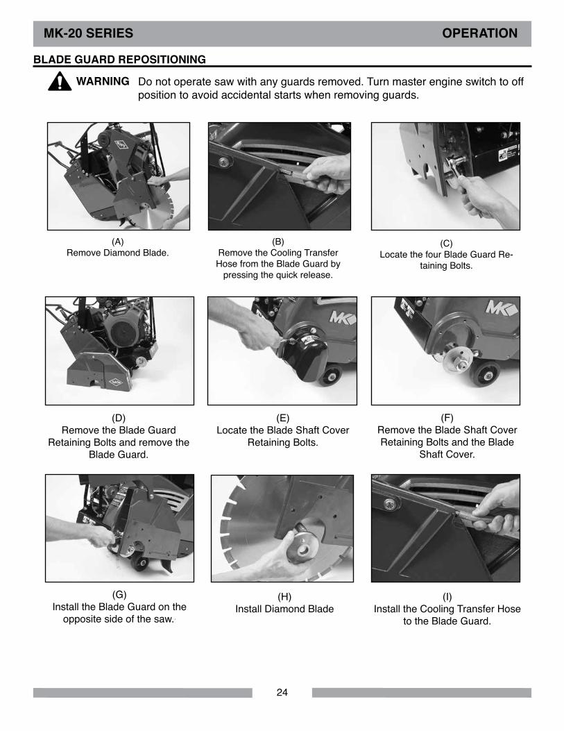
BlAdE GUARd REPoSITIoNING
(A)Remove Diamond Blade.
(B)Remove the Cooling Transfer Hose from the Blade Guard by
pressing the quick release.
(D)Remove the Blade Guard
Retaining Bolts and remove the Blade Guard.
(C)Locate the four Blade Guard Re-
taining Bolts.
(E)Locate the Blade Shaft Cover
Retaining Bolts.
(F)Remove the Blade Shaft Cover Retaining Bolts and the Blade
Shaft Cover.
(G)Install the Blade Guard on the
opposite side of the saw..
(H)Install Diamond Blade
(I)Install the Cooling Transfer Hose
to the Blade Guard.
Do not operate saw with any guards removed. Turn master engine switch to off position to avoid accidental starts when removing guards.
WARNING
25
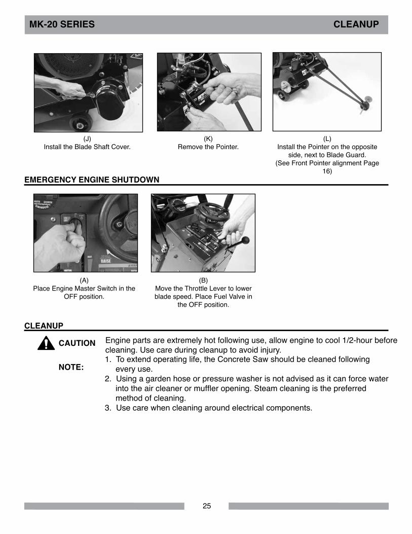
MK-20 SERIES ClEANUP
(J)Install the Blade Shaft Cover.
(L)Install the Pointer on the opposite
side, next to Blade Guard. (See Front Pointer alignment Page
16)
(K)Remove the Pointer.
EMERGENCY ENGINE SHUTdoWN
(A)Place Engine Master Switch in the
OFF position.
(B)Move the Throttle Lever to lower blade speed. Place Fuel Valve in
the OFF position.
ClEANUPEngine parts are extremely hot following use, allow engine to cool 1/2-hour before cleaning. Use care during cleanup to avoid injury.
CAUTIoN
1. To extend operating life, the Concrete Saw should be cleaned following every use.2. Using a garden hose or pressure washer is not advised as it can force water into the air cleaner or muffler opening. Steam cleaning is the preferred method of cleaning.3. Use care when cleaning around electrical components.
NoTE:

26
MK-20 SERIES MAINTENANCE
(C)Clean the remainder of the exterior
surface (except the engine).
MAINTENANCE SCHEdUlEItem should be performed at every indicated hour(s) or interval period whichever goes first.
Maintenance Schedule Maintenance operation
daily 25 Hours or Weekly
100 Hours or Seasonal
Air FilterCheck
Every 4 Hours When Dry CuttingEvery 8 Hours When Wet Cutting
Change Air Filter •Hydrostatic Transmission/Reservoir Check oil •Mainframe Blade Shaft
BearingsLube Blade Shaft Bearings at end of Operations
Pivot Bearings •Chain drive •
Adjust Tension
•Transmission Control Assemblies •Battery •V-Belts •
Replace
•Battery Check Water level •Engine Definitive information on engine maintenance is contained in the Engine Manual
provided separately. Perform all maintenance procedures as recommended by the engine manual.
(A)Verify the engine is off and cool be-fore beginning to clean. Clean the
saw with soap and water.
(B)Clean water system outlets,
including water tubes in blade guard.

27
• Always turn the master engine switch to the off position.• NEVER lubricate components or attempt service on a running machine.• Keep the machinery in proper running condition.• Fix damage to the machine immediately and always replace broken parts, or missing decals.
MK-20 SERIES MAINTENANCE
NEW MAINTENANCEPerform the following after initial purchase and operation of the saw.
(A)Change engine oil after
first month or first 20 operating hours (See Engine Manual).
(B)Check and adjust tension on
all belts following first48 hours of operation.
MAINTENANCE SAFETY
Maintenance Following Use
The following maintenance should be performed following each use.
(A)Shut down the Engine. Let saw cool
before proceeding.
(B)Check Air Filter
(See Engine Manual).
(C)Lubricate the Grease Fitting on the
Blade Shaft.
28
MK-20 SERIES MAINTENANCE
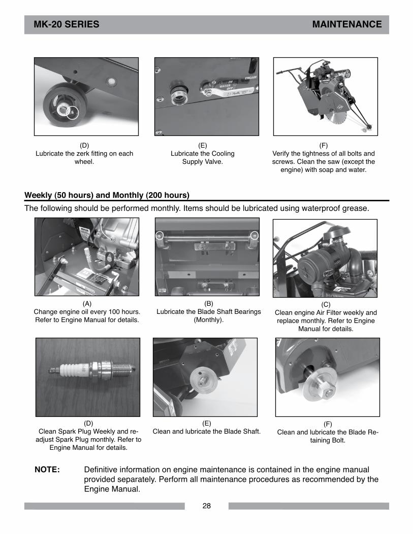
Weekly (50 hours) and Monthly (200 hours) The following should be performed monthly. Items should be lubricated using waterproof grease.
(A)Change engine oil every 100 hours. Refer to Engine Manual for details.
(B)Lubricate the Blade Shaft Bearings
(Monthly).
(C)Clean engine Air Filter weekly and replace monthly. Refer to Engine
Manual for details.
(D)Clean Spark Plug Weekly and re-
adjust Spark Plug monthly. Refer to Engine Manual for details.
(E)Clean and lubricate the Blade Shaft.
(F)Clean and lubricate the Blade Re-
taining Bolt.
Definitive information on engine maintenance is contained in the engine manual provided separately. Perform all maintenance procedures as recommended by the Engine Manual.
NoTE:
(D)Lubricate the zerk fitting on each
wheel.
(E)Lubricate the Cooling
Supply Valve.
(F)Verify the tightness of all bolts and screws. Clean the saw (except the
engine) with soap and water.

29
MK-20 SERIES MAINTENANCE
500 Hours and 1000 Hour MaintenancePerform the following maintenance every 500 hours.
(A)Replace Spark Plug. Refer to En-
gine Manual for details.
(B)Have Authorized Repair Shop per-
form 500-hour maintenance.
(C)Have Authorized Repair Shop per-
form 1000-hour maintenance.
Yearly and Two-Year MaintenancePerform the following maintenance every year.
(A)Inspect belts for proper tension
and wear.
30
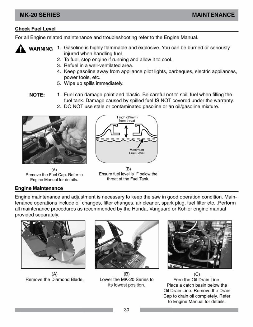
MK-20 SERIES MAINTENANCE
Check Fuel level
1. Gasoline is highly flammable and explosive. You can be burned or seriously injured when handling fuel.2. To fuel, stop engine if running and allow it to cool.3. Refuel in a well-ventilated area.4. Keep gasoline away from appliance pilot lights, barbeques, electric appliances, power tools, etc.5. Wipe up spills immediately.
NoTE:
WARNING
1. Fuel can damage paint and plastic. Be careful not to spill fuel when filling the fuel tank. Damage caused by spilled fuel IS NOT covered under the warranty.2. DO NOT use stale or contaminated gasoline or an oil/gasoline mixture.
(A)Remove the Fuel Cap. Refer to
Engine Manual for details.
For all Engine related maintenance and troubleshooting refer to the Engine Manual.
(B)Ensure fuel level is 1” below the
throat of the Fuel Tank.
1 inch (25mm) from throat
Maximum Fuel Level
Engine Maintenance
(A)Remove the Diamond Blade.
(B)Lower the MK-20 Series to
its lowest position.
(C)Free the Oil Drain Line.
Place a catch basin below the Oil Drain Line. Remove the Drain Cap to drain oil completely. Refer
to Engine Manual for details.
Engine maintenance and adjustment is necessary to keep the saw in good operation condition. Main-tenance operations include oil changes, filter changes, air cleaner, spark plug, fuel filter etc...Perform all maintenance procedures as recommended by the Honda, Vanguard or Kohler engine manual provided separately.

31
MK-20 SERIES MAINTENANCE
Engine Air Filter Inspection, Cleaning and Replacement
(A)Clean the Air Filter. Refer to Engine Manual for details.
For all Engine related maintenance and troubleshooting refer to the Engine Manual.
Spark Plug Adjustments and Replacement
Electrical System
(A)When installing the Spark Plug,
ensure the threads are aligned with the threads in the engine so as not to
“cross-thread” the plug.
CAUTIoN
CAUTIoN
DO NOT work around the engine while hot.
If the fuse blows, determine the cause of the problem before resuming operations.
A fuse protects the battery charging circuit. The fuse and the battery are the only user serviceable parts of the electrical system, a short circuit or a battery connected in reverse polarity will blow the fuse. Refer to the Engine Manual for the location and type of fuse. The fuse on the Engine is located between the starter solenoid and the engine, and is rated at 30 amps.

32
Check water level weekly. Add distilled water if necessary. Check terminal cables and remove any de-posits. Remove the battery for recharging and follow the instructions for recharging. Damage can result to the battery and electrical system if the battery is charged or installed in reverse polarity. Make sure that the negative terminal is connected to ground.
MK-20 SERIES MAINTENANCE
Belt Adjustment and Replacement
This machine is equipped with two heavy duty V-belts which are tensioned properly at the factory. These must be re-tensioned after the first half day of operation and periodically thereafter. Adjust to the original tension as set at the factory, which is approximately 1/4 inch of defection of the center of the belt halfway between the pulley on the motor and the pulley on the blade shaft.To adjust belt tension, first remove the belt guard. With the belt guard removed, loosen motor mount bolts. Loosen the lock nut and adjust set bolt on the motor tension adjuster until the required belt tension is achieved.Retighten the motor mounting bolts.
Battery
CAUTIoN
CAUTIoN
Observe all battery precautions as outlined in the Assembly Section of this manual.
(A) (B)
The two most common causes of misalignment are shown in the drawings.
Gap between steel straight edge and sheave.
NoTE:
A. the engine drive shaft and the blade shaft are not parallel.B. the pulleys are not located properly on the shafts.
do NoT oVER TENSIoN as damage to belts and bearings may occur. Belts that are too loose may slip, resulting in short life and loss of power to the blade shaft. If any belts are worn or damaged, replace the complete set.The motor mounting plate must be maintained parallel to the frame. Make sure all lock nuts are tightened and retighten the bracket bolts.
Never make adjustments to belts or pulleys while engine is running.
Remove and install battery as per instructions in Assembly Section of this manual. Be careful not to contact metal while loosening positive terminal with tools.

33
NoTES

34
MK-20 SERIES EXPlodEd VIEW
1
2
3
4
5
6
7
8
9
11
12
13
14
15
16
17
18
19
20
21
22
23
24
25
26
27
29
30
31
32
33
5
4
4
6
10
10
4
4 4
6
6 6
12
12
12
28
1.
FIGURE 1 - PARTS lIST: MK-2020HSP CoNCRETE SAW - P/N 156498
35
MK-20 SERIES PARTS lIST
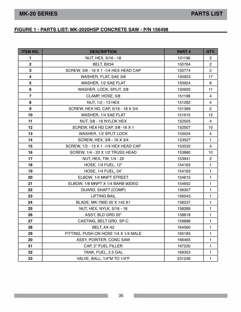
FIGURE 1 - PARTS lIST: MK-2020HSP CoNCRETE SAW - P/N 156498
ITEM No. dESCRIPTIoN PART # QTY. 1 NUT, HEX, 5/16 - 18 101196 22 BELT, BX34 150764 23 SCREW, 3/8 - 16 X 1 -1/4 HEX HEAD CAP 150774 24 WASHER, FLAT, SAE 3/8 150923 175 WASHER, 1/2 SAE FLAT 150924 86 WASHER, LOCK, SPLIT, 3/8 150925 117 CLAMP, HOSE, 5/8 151198 48 NUT, 1/2 - 13 HEX 151282 49 SCREW, HEX HD, CAP, 5/16 - 18 X 3/4 151369 210 WASHER, 1/4 SAE FLAT 151915 1211 NUT, 3/8 - 16 NYLOK HEX 152505 412 SCREW, HEX HD CAP, 3/8 -16 X 1 152507 1013 WASHER, 1/2 SPLIT LOCK 153524 414 SCREW, HEX, 3/8 - 16 X 3/4 153527 115 SCREW, 1/2 - 13 X 1 -1/4 HEX HEAD CAP 153532 416 SCREW, 1/4 - 20 X 1/2 TRUSS HEAD 153880 1017 NUT, HEX, TW, 1/4 - 20 153941 218 HOSE, 1/4 FUEL, 12” 154163 119 HOSE, 1/4 FUEL, 24” 154163 120 ELBOW, 1/4 MNPT STREET 154615 121 ELBOW, 1/8 MNPT X 1/4 BARB 90DEG 154652 122 GUARD, SHAFT (COMP) 156307 123 LIFTING BAIL 156543 124 BLADE, MK-799D 20 X 142 X1 158237 125 NUT, HEX, NYLK, 5/16 - 18 158289 126 ASSY, BLD GRD 20” 158818 127 CASTING, BELT GRD, SP-C 159888 128 BELT, AX-42 164560 129 FITTING, PUSH ON HOSE 1/4 X 1/4 MALE 165183 130 ASSY, POINTER, CONC SAW 166465 131 CAP, 2” FUEL FILLER 167220 132 TANK, FUEL, 2.5 GAL 169353 133 VALVE, BALL, 1/4”M TO 1/4”F 231248 1

36
MK-20 SERIES EXPlodEd VIEW
FIGURE 1 - PARTS lIST: MK-2020HSP CoNCRETE SAW - P/N 156498
37
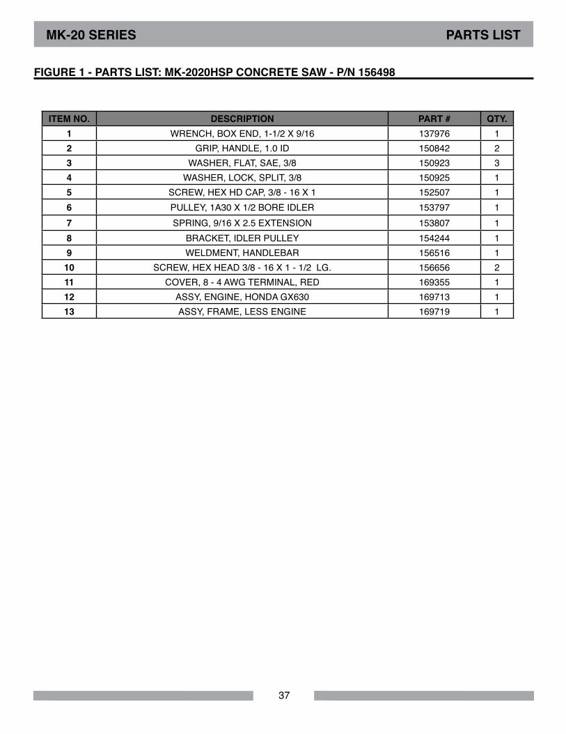
ITEM No. dESCRIPTIoN PART # QTY. 1 WRENCH, BOX END, 1-1/2 X 9/16 137976 12 GRIP, HANDLE, 1.0 ID 150842 23 WASHER, FLAT, SAE, 3/8 150923 34 WASHER, LOCK, SPLIT, 3/8 150925 15 SCREW, HEX HD CAP, 3/8 - 16 X 1 152507 16 PULLEY, 1A30 X 1/2 BORE IDLER 153797 17 SPRING, 9/16 X 2.5 EXTENSION 153807 18 BRACKET, IDLER PULLEY 154244 19 WELDMENT, HANDLEBAR 156516 110 SCREW, HEX HEAD 3/8 - 16 X 1 - 1/2 LG. 156656 211 COVER, 8 - 4 AWG TERMINAL, RED 169355 112 ASSY, ENGINE, HONDA GX630 169713 113 ASSY, FRAME, LESS ENGINE 169719 1
MK-20 SERIES PARTS lIST
FIGURE 1 - PARTS lIST: MK-2020HSP CoNCRETE SAW - P/N 156498

38
1
2
3
4 5
6
7
8
9
10
11
12
13
14
15
16
17
18 19
20
22
23
24
25
26
27
1
1
1
2
2 2
2
2
2
28
21
MK-20 SERIES EXPlodEd VIEW
FIGURE 1 - PARTS lIST: MK-2020HSP CoNCRETE SAW - P/N 156498
39
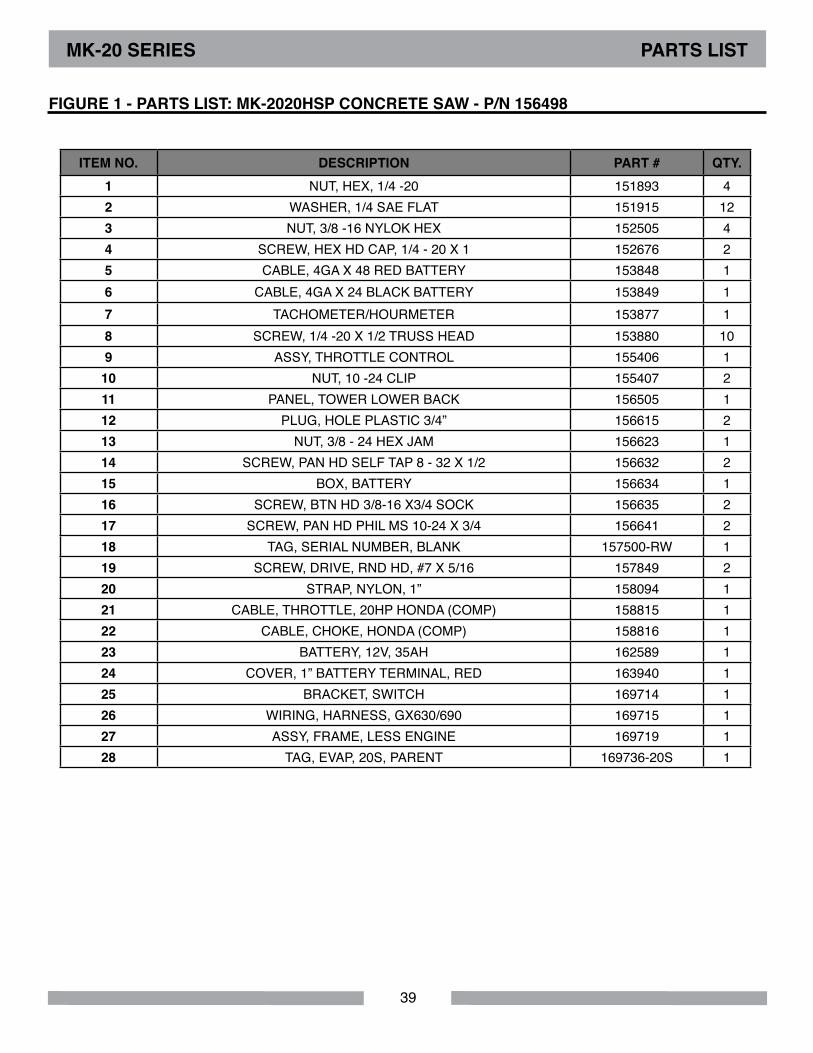
ITEM No. dESCRIPTIoN PART # QTY. 1 NUT, HEX, 1/4 -20 151893 42 WASHER, 1/4 SAE FLAT 151915 123 NUT, 3/8 -16 NYLOK HEX 152505 44 SCREW, HEX HD CAP, 1/4 - 20 X 1 152676 25 CABLE, 4GA X 48 RED BATTERY 153848 16 CABLE, 4GA X 24 BLACK BATTERY 153849 17 TACHOMETER/HOURMETER 153877 18 SCREW, 1/4 -20 X 1/2 TRUSS HEAD 153880 109 ASSY, THROTTLE CONTROL 155406 1
10 NUT, 10 -24 CLIP 155407 211 PANEL, TOWER LOWER BACK 156505 112 PLUG, HOLE PLASTIC 3/4” 156615 213 NUT, 3/8 - 24 HEX JAM 156623 114 SCREW, PAN HD SELF TAP 8 - 32 X 1/2 156632 215 BOX, BATTERY 156634 116 SCREW, BTN HD 3/8-16 X3/4 SOCK 156635 217 SCREW, PAN HD PHIL MS 10-24 X 3/4 156641 218 TAG, SERIAL NUMBER, BLANK 157500-RW 119 SCREW, DRIVE, RND HD, #7 X 5/16 157849 220 STRAP, NYLON, 1” 158094 121 CABLE, THROTTLE, 20HP HONDA (COMP) 158815 122 CABLE, CHOKE, HONDA (COMP) 158816 123 BATTERY, 12V, 35AH 162589 124 COVER, 1” BATTERY TERMINAL, RED 163940 125 BRACKET, SWITCH 169714 126 WIRING, HARNESS, GX630/690 169715 127 ASSY, FRAME, LESS ENGINE 169719 128 TAG, EVAP, 20S, PARENT 169736-20S 1
MK-20 SERIES PARTS lIST
FIGURE 1 - PARTS lIST: MK-2020HSP CoNCRETE SAW - P/N 156498
40
1
2
3
4
5
6
7
8
9
11
12
13
14
15
16
17
18
19
20
21
22
23
24
25
26
27
28
29
30
31
32
33
34
5
4
4
6
10
10
4
4 4
6
6 6
12
12
12
1.
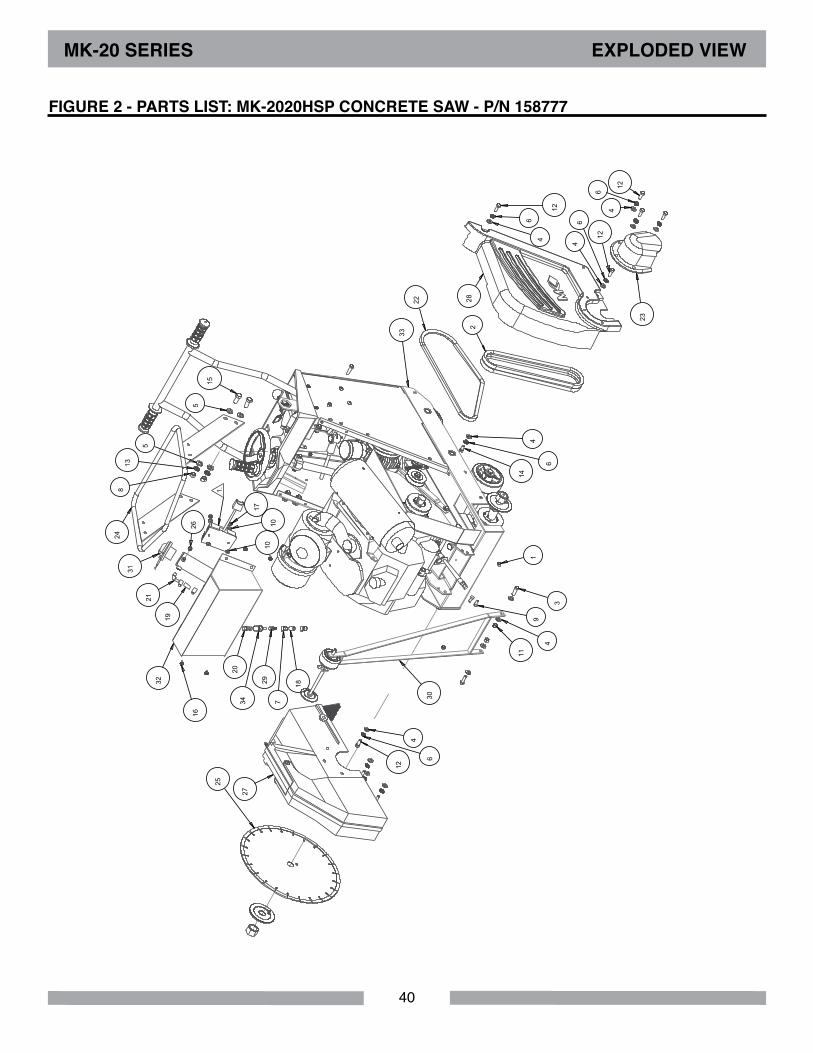
FIGURE 2 - PARTS lIST: MK-2020HSP CoNCRETE SAW - P/N 158777
MK-20 SERIES EXPlodEd VIEW
41
MK-20 SERIES PARTS lIST
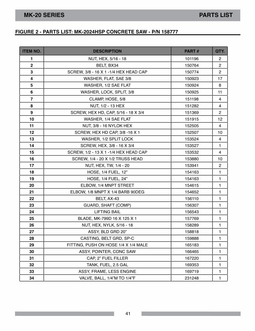
FIGURE 2 - PARTS lIST: MK-2024HSP CoNCRETE SAW - P/N 158777
ITEM No. dESCRIPTIoN PART # QTY.
1 NUT, HEX, 5/16 - 18 101196 22 BELT, BX34 150764 23 SCREW, 3/8 - 16 X 1 -1/4 HEX HEAD CAP 150774 24 WASHER, FLAT, SAE 3/8 150923 175 WASHER, 1/2 SAE FLAT 150924 86 WASHER, LOCK, SPLIT, 3/8 150925 117 CLAMP, HOSE, 5/8 151198 48 NUT, 1/2 - 13 HEX 151282 49 SCREW, HEX HD, CAP, 5/16 - 18 X 3/4 151369 210 WASHER, 1/4 SAE FLAT 151915 1211 NUT, 3/8 - 16 NYLOK HEX 152505 412 SCREW, HEX HD CAP, 3/8 -16 X 1 152507 1013 WASHER, 1/2 SPLIT LOCK 153524 414 SCREW, HEX, 3/8 - 16 X 3/4 153527 115 SCREW, 1/2 - 13 X 1 -1/4 HEX HEAD CAP 153532 416 SCREW, 1/4 - 20 X 1/2 TRUSS HEAD 153880 1017 NUT, HEX, TW, 1/4 - 20 153941 218 HOSE, 1/4 FUEL, 12” 154163 119 HOSE, 1/4 FUEL, 24” 154163 120 ELBOW, 1/4 MNPT STREET 154615 121 ELBOW, 1/8 MNPT X 1/4 BARB 90DEG 154652 122 BELT, AX-43 156110 123 GUARD, SHAFT (COMP) 156307 124 LIFTING BAIL 156543 125 BLADE, MK-799D 16 X 125 X 1 157769 126 NUT, HEX, NYLK, 5/16 - 18 158289 127 ASSY, BLD GRD 20” 158818 128 CASTING, BELT GRD, SP-C 159888 129 FITTING, PUSH ON HOSE 1/4 X 1/4 MALE 165183 130 ASSY, POINTER, CONC SAW 166465 131 CAP, 2” FUEL FILLER 167220 132 TANK, FUEL, 2.5 GAL 169353 133 ASSY, FRAME, LESS ENGINE 169719 134 VALVE, BALL, 1/4”M TO 1/4”F 231248 1
42
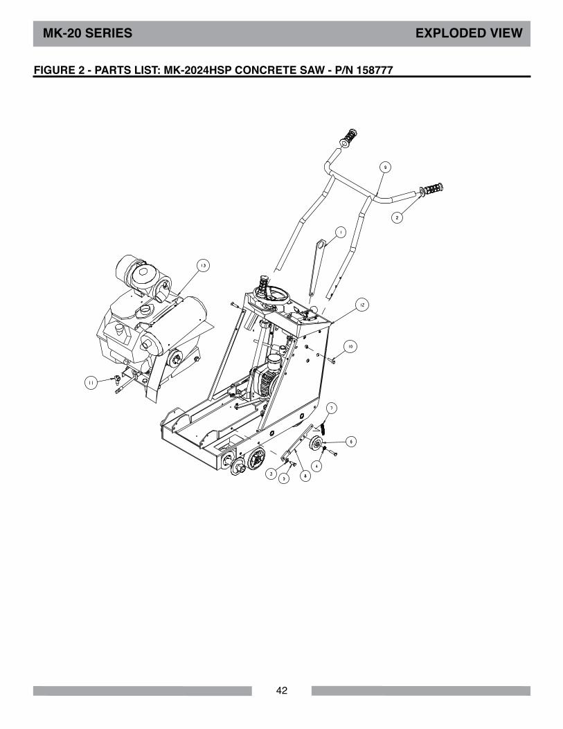
MK-20 SERIES EXPlodEd VIEW
FIGURE 2 - PARTS lIST: MK-2024HSP CoNCRETE SAW - P/N 158777
43
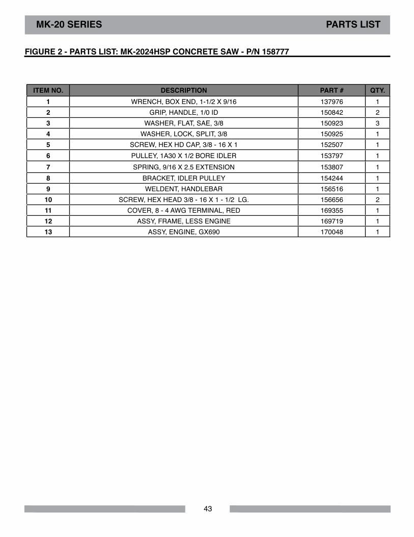
MK-20 SERIES PARTS lIST
FIGURE 2 - PARTS lIST: MK-2024HSP CoNCRETE SAW - P/N 158777
ITEM No. dESCRIPTIoN PART # QTY. 1 WRENCH, BOX END, 1-1/2 X 9/16 137976 12 GRIP, HANDLE, 1/0 ID 150842 23 WASHER, FLAT, SAE, 3/8 150923 34 WASHER, LOCK, SPLIT, 3/8 150925 15 SCREW, HEX HD CAP, 3/8 - 16 X 1 152507 16 PULLEY, 1A30 X 1/2 BORE IDLER 153797 17 SPRING, 9/16 X 2.5 EXTENSION 153807 18 BRACKET, IDLER PULLEY 154244 19 WELDENT, HANDLEBAR 156516 110 SCREW, HEX HEAD 3/8 - 16 X 1 - 1/2 LG. 156656 211 COVER, 8 - 4 AWG TERMINAL, RED 169355 112 ASSY, FRAME, LESS ENGINE 169719 113 ASSY, ENGINE, GX690 170048 1
44
MK-20 SERIES EXPlodEd VIEW & PARTS lIST
1
2
3
4 5
6
7
8
9
10
11
12
13
14
15
16
17
18
19
21
22 23
24
25
26
1
1
1
2
2 2
2
2
2 2
4
20
27
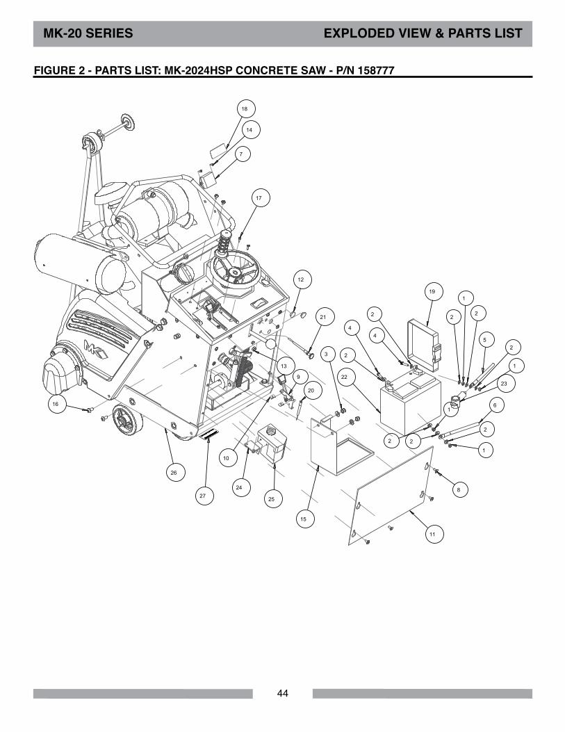
FIGURE 2 - PARTS lIST: MK-2024HSP CoNCRETE SAW - P/N 158777
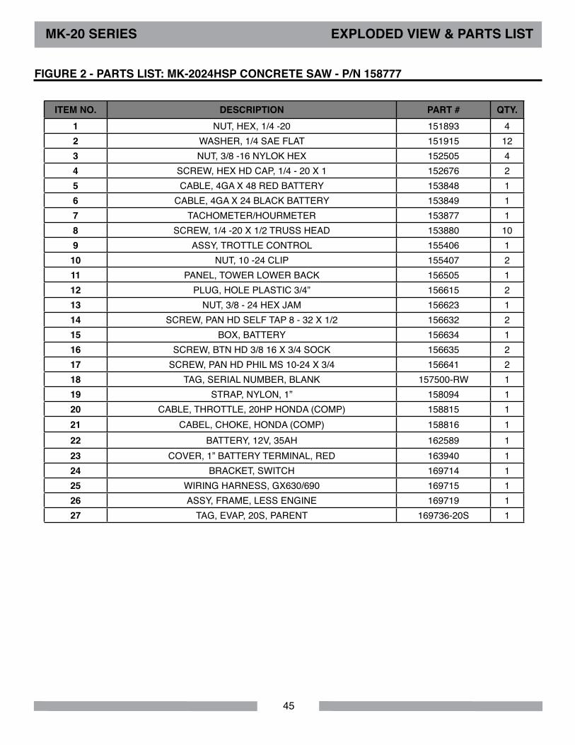
45
FIGURE 2 - PARTS lIST: MK-2024HSP CoNCRETE SAW - P/N 158777
ITEM No. dESCRIPTIoN PART # QTY. 1 NUT, HEX, 1/4 -20 151893 42 WASHER, 1/4 SAE FLAT 151915 123 NUT, 3/8 -16 NYLOK HEX 152505 44 SCREW, HEX HD CAP, 1/4 - 20 X 1 152676 25 CABLE, 4GA X 48 RED BATTERY 153848 16 CABLE, 4GA X 24 BLACK BATTERY 153849 17 TACHOMETER/HOURMETER 153877 18 SCREW, 1/4 -20 X 1/2 TRUSS HEAD 153880 109 ASSY, TROTTLE CONTROL 155406 1
10 NUT, 10 -24 CLIP 155407 211 PANEL, TOWER LOWER BACK 156505 112 PLUG, HOLE PLASTIC 3/4” 156615 213 NUT, 3/8 - 24 HEX JAM 156623 114 SCREW, PAN HD SELF TAP 8 - 32 X 1/2 156632 215 BOX, BATTERY 156634 116 SCREW, BTN HD 3/8 16 X 3/4 SOCK 156635 217 SCREW, PAN HD PHIL MS 10-24 X 3/4 156641 218 TAG, SERIAL NUMBER, BLANK 157500-RW 119 STRAP, NYLON, 1” 158094 120 CABLE, THROTTLE, 20HP HONDA (COMP) 158815 121 CABEL, CHOKE, HONDA (COMP) 158816 122 BATTERY, 12V, 35AH 162589 123 COVER, 1” BATTERY TERMINAL, RED 163940 124 BRACKET, SWITCH 169714 125 WIRING HARNESS, GX630/690 169715 126 ASSY, FRAME, LESS ENGINE 169719 127 TAG, EVAP, 20S, PARENT 169736-20S 1
MK-20 SERIES EXPlodEd VIEW & PARTS lIST
46
MK-20 SERIES EXPlodEd VIEW & PARTS lIST
1
2
3
5
8
9
10
13
14
16
6
4
7
15
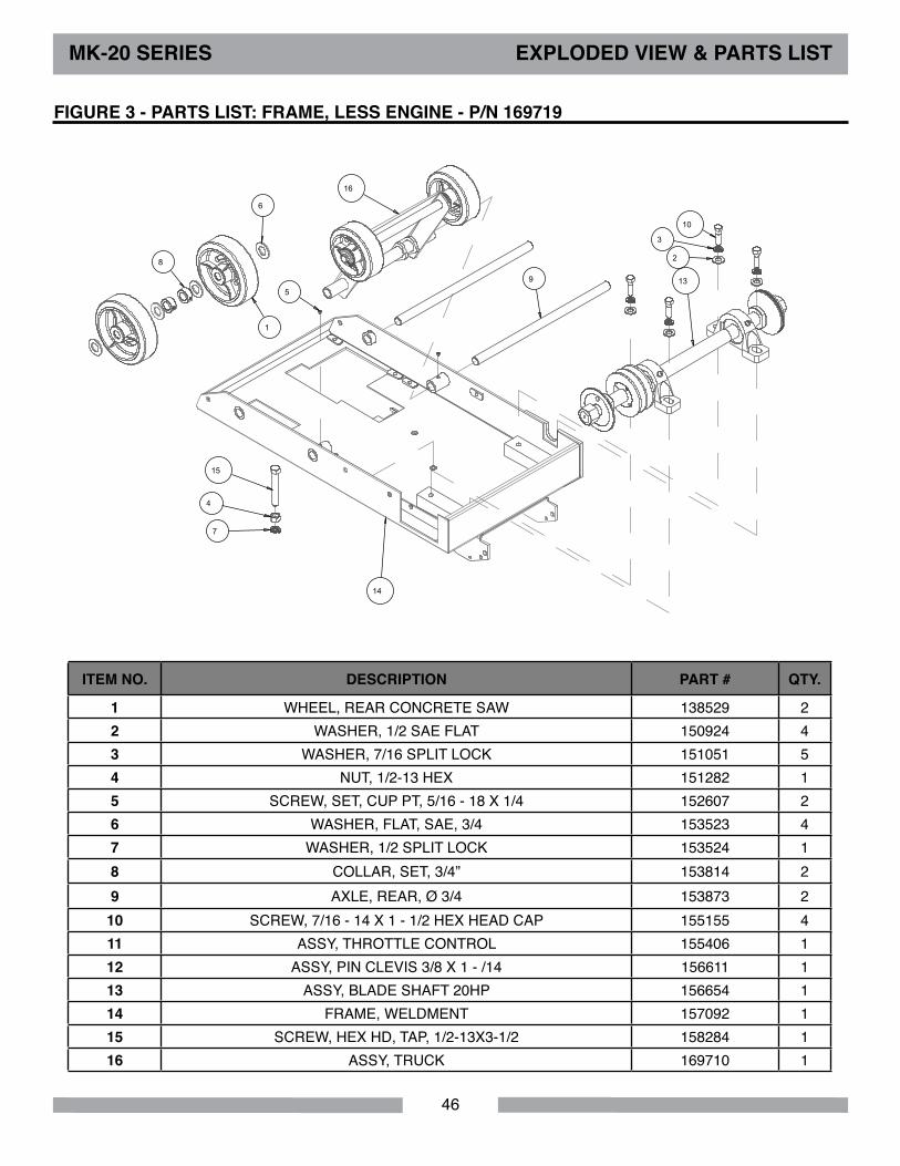
FIGURE 3 - PARTS lIST: FRAME, lESS ENGINE - P/N 169719
ITEM No. dESCRIPTIoN PART # QTY.
1 WHEEL, REAR CONCRETE SAW 138529 22 WASHER, 1/2 SAE FLAT 150924 43 WASHER, 7/16 SPLIT LOCK 151051 54 NUT, 1/2-13 HEX 151282 15 SCREW, SET, CUP PT, 5/16 - 18 X 1/4 152607 26 WASHER, FLAT, SAE, 3/4 153523 47 WASHER, 1/2 SPLIT LOCK 153524 18 COLLAR, SET, 3/4” 153814 29 AXLE, REAR, Ø 3/4 153873 210 SCREW, 7/16 - 14 X 1 - 1/2 HEX HEAD CAP 155155 411 ASSY, THROTTLE CONTROL 155406 112 ASSY, PIN CLEVIS 3/8 X 1 - /14 156611 113 ASSY, BLADE SHAFT 20HP 156654 114 FRAME, WELDMENT 157092 115 SCREW, HEX HD, TAP, 1/2-13X3-1/2 158284 116 ASSY, TRUCK 169710 1
47
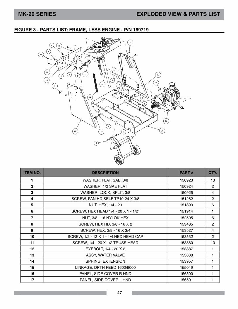
MK-20 SERIES EXPlodEd VIEW & PARTS lIST
FIGURE 3 - PARTS lIST: FRAME, lESS ENGINE - P/N 169719
ITEM No. dESCRIPTIoN PART # QTY.
1 WASHER, FLAT, SAE, 3/8 150923 132 WASHER, 1/2 SAE FLAT 150924 23 WASHER, LOCK, SPLIT, 3/8 150925 44 SCREW, PAN HD SELF TP10-24 X 3/8 151262 25 NUT, HEX, 1/4 - 20 151893 66 SCREW, HEX HEAD 1/4 - 20 X 1 - 1/2” 151914 17 NUT, 3/8 - 16 NYLOK HEX 152505 68 SCREW, HEX HD, 3/8 - 16 X 2 153485 29 SCREW, HEX, 3/8 - 16 X 3/4 153527 4
10 SCREW, 1/2 - 13 X 1 - 1/4 HEX HEAD CAP 153532 211 SCREW, 1/4 - 20 X 1/2 TRUSS HEAD 153880 1012 EYEBOLT, 1/4 - 20 X 2 153887 113 ASSY, WATER VALVE 153888 114 SPRING, EXTENSION 153957 115 LINKAGE, DPTH FEED 1600/9000 155049 116 PANEL, SIDE COVER R HND 156500 117 PANEL, SIDE COVER L HND 156501 1

48
ITEM No. dESCRIPTIoN PART # QTY.
18 PANEL, TOWER UPPER 156504 119 ASSY, PIN CLEVIS 3/8 X 1 - 1/4 156611 120 CABLE, TRANSMIS HONDA 2013HSP-C 156643 121 PLUG, 1/2 FLUSH HEAD BUTTON 156779 122 FRAME, WELDMENT 157092 123 ASSY, TRANSMISSION 169711 1
MK-20 SERIES EXPlodEd VIEW & PARTS lIST
FIGURE 3 - PARTS lIST: FRAME, lESS ENGINE - P/N 169719
1
2
3
4
5
6
7
8
9
10
11 12
13
14
15
16
17
18
19
20 21
22
23
24
25
26
27
28
29
30
31
32
33
35
37
38
39
1 1
1
1
1
1
6 6
6
7
36
49
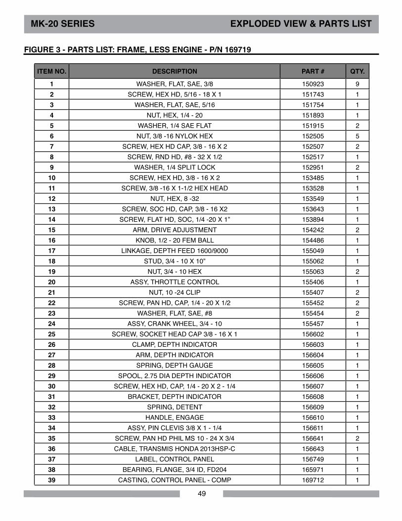
ITEM No. dESCRIPTIoN PART # QTY.
1 WASHER, FLAT, SAE, 3/8 150923 92 SCREW, HEX HD, 5/16 - 18 X 1 151743 13 WASHER, FLAT, SAE, 5/16 151754 14 NUT, HEX, 1/4 - 20 151893 15 WASHER, 1/4 SAE FLAT 151915 26 NUT, 3/8 -16 NYLOK HEX 152505 57 SCREW, HEX HD CAP, 3/8 - 16 X 2 152507 28 SCREW, RND HD, #8 - 32 X 1/2 152517 19 WASHER, 1/4 SPLIT LOCK 152951 210 SCREW, HEX HD, 3/8 - 16 X 2 153485 111 SCREW, 3/8 -16 X 1-1/2 HEX HEAD 153528 112 NUT, HEX, 8 -32 153549 113 SCREW, SOC HD, CAP, 3/8 - 16 X2 153643 114 SCREW, FLAT HD, SOC, 1/4 -20 X 1” 153894 115 ARM, DRIVE ADJUSTMENT 154242 216 KNOB, 1/2 - 20 FEM BALL 154486 117 LINKAGE, DEPTH FEED 1600/9000 155049 118 STUD, 3/4 - 10 X 10” 155062 119 NUT, 3/4 - 10 HEX 155063 220 ASSY, THROTTLE CONTROL 155406 121 NUT, 10 -24 CLIP 155407 222 SCREW, PAN HD, CAP, 1/4 - 20 X 1/2 155452 223 WASHER, FLAT, SAE, #8 155454 224 ASSY, CRANK WHEEL, 3/4 - 10 155457 125 SCREW, SOCKET HEAD CAP 3/8 - 16 X 1 156602 126 CLAMP, DEPTH INDICATOR 156603 127 ARM, DEPTH INDICATOR 156604 128 SPRING, DEPTH GAUGE 156605 129 SPOOL, 2.75 DIA DEPTH INDICATOR 156606 130 SCREW, HEX HD, CAP, 1/4 - 20 X 2 - 1/4 156607 131 BRACKET, DEPTH INDICATOR 156608 132 SPRING, DETENT 156609 133 HANDLE, ENGAGE 156610 134 ASSY, PIN CLEVIS 3/8 X 1 - 1/4 156611 135 SCREW, PAN HD PHIL MS 10 - 24 X 3/4 156641 236 CABLE, TRANSMIS HONDA 2013HSP-C 156643 137 LABEL, CONTROL PANEL 156749 138 BEARING, FLANGE, 3/4 ID, FD204 165971 139 CASTING, CONTROL PANEL - COMP 169712 1
MK-20 SERIES EXPlodEd VIEW & PARTS lIST
FIGURE 3 - PARTS lIST: FRAME, lESS ENGINE - P/N 169719
50
MK-20 SERIES EXPlodEd VIEW & PARTS lIST
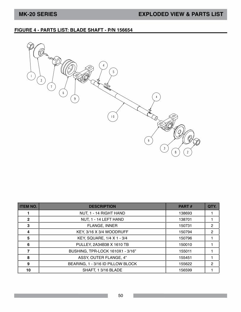
FIGURE 4 - PARTS lIST: BlAdE SHAFT - P/N 156654
ITEM No. dESCRIPTIoN PART # QTY. 1 NUT, 1 - 14 RIGHT HAND 138693 12 NUT, 1 - 14 LEFT HAND 138701 13 FLANGE, INNER 150731 24 KEY, 3/16 X 3/4 WOODRUFF 150794 25 KEY, SQUARE, 1/4 X 1 - 3/4 150796 16 PULLEY, 2A34B38 X 1610 TB 150010 17 BUSHING, TPR-LOCK 1610X1 - 3/16” 155011 18 ASSY, OUTER FLANGE, 4” 155451 19 BEARING, 1 - 3/16 ID PILLOW BLOCK 155622 210 SHAFT, 1 3/16 BLADE 156599 1

51
MK-20 SERIES EXPlodEd VIEW & PARTS lIST
ITEM No. dESCRIPTIoN PART # QTY. 1 KEY, SQUARE, 1/4 X 1 - 3/4 150796 12 WASHER, FLAT, SAE, 3/8 150923 83 WASHER, 1/2 SAE FLAT 150924 34 WASHER, LOCK, SPLIT, 5/16 151747 45 WASHER, FLAT, SAE, 5/16 151754 46 NUT, 3/8 - 16 NYLOK HEX 152505 47 SCREW, HEX HD, 3/8 - 16 X 2 153485 48 WASHER, 1/2 SPLIT LOCK 153524 29 SCREW, 1/2 - 13 X 1 - 1/4 HEX HEAD CAP 153532 410 BOLT, HEX, TAP, 1/2 - 13 X 4 153854 111 MOUNT, ENGINE 154237 112 BUSHING, TPR - LOCK 1210 X 1 - 1/8” 154430 113 ELBOW, 1/8 MNPT X 1/4 BARB 90DEG 154652 114 PULLEY, 3A30B34 X 1210TB REV 155009 115 ASSY, OIL DRAIN, 14MM 157577-03 116 GUARD, INNER BELT 165608 117 SCREW, 5/16 - 24 X 3/4 HEX HEAD MACHINE 165617 418 ENGINE, HONDA GX630 169592 119 ASSY, 7” AIR CLEANER 169593 120 MUFFLER, HONDA 20HP 621600 169594 121 WASHER, 1/2 SAE FLAT 169958 1
FIGURE 5 - PARTS lIST: ENGINE, HoNdA GX630 - P/N 169713
52
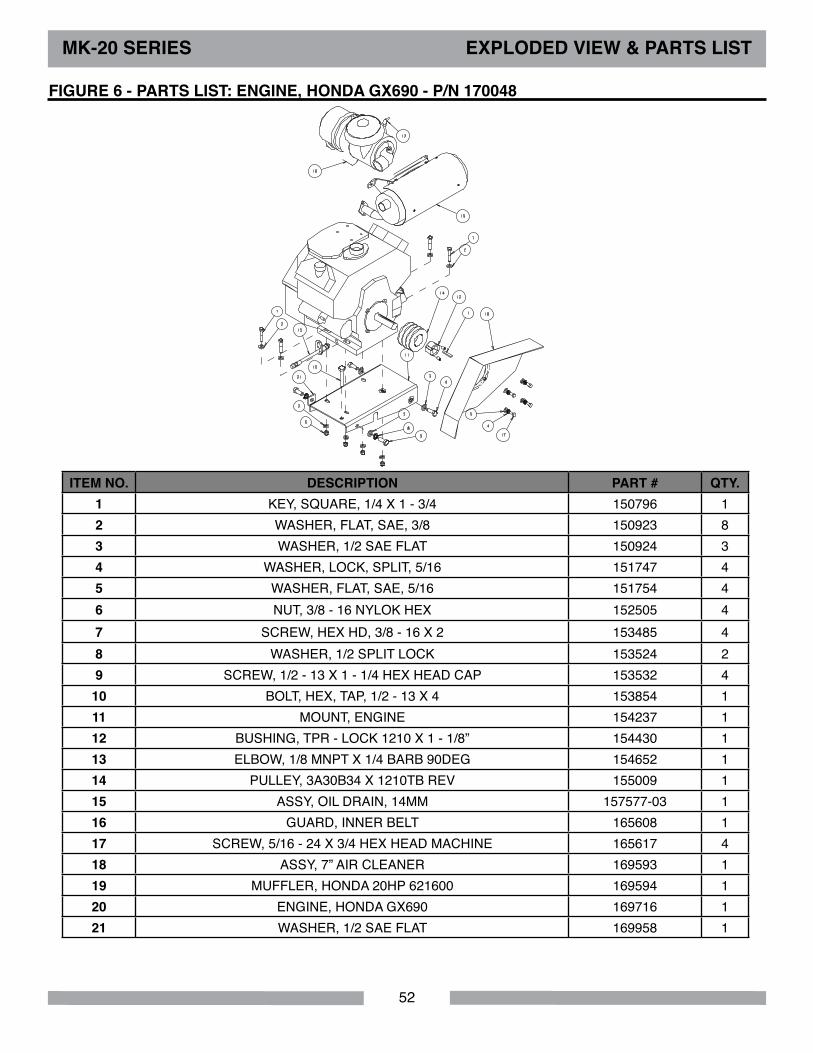
ITEM No. dESCRIPTIoN PART # QTY. 1 KEY, SQUARE, 1/4 X 1 - 3/4 150796 12 WASHER, FLAT, SAE, 3/8 150923 83 WASHER, 1/2 SAE FLAT 150924 34 WASHER, LOCK, SPLIT, 5/16 151747 45 WASHER, FLAT, SAE, 5/16 151754 46 NUT, 3/8 - 16 NYLOK HEX 152505 47 SCREW, HEX HD, 3/8 - 16 X 2 153485 48 WASHER, 1/2 SPLIT LOCK 153524 29 SCREW, 1/2 - 13 X 1 - 1/4 HEX HEAD CAP 153532 410 BOLT, HEX, TAP, 1/2 - 13 X 4 153854 111 MOUNT, ENGINE 154237 112 BUSHING, TPR - LOCK 1210 X 1 - 1/8” 154430 113 ELBOW, 1/8 MNPT X 1/4 BARB 90DEG 154652 114 PULLEY, 3A30B34 X 1210TB REV 155009 115 ASSY, OIL DRAIN, 14MM 157577-03 116 GUARD, INNER BELT 165608 117 SCREW, 5/16 - 24 X 3/4 HEX HEAD MACHINE 165617 418 ASSY, 7” AIR CLEANER 169593 119 MUFFLER, HONDA 20HP 621600 169594 120 ENGINE, HONDA GX690 169716 121 WASHER, 1/2 SAE FLAT 169958 1
FIGURE 6 - PARTS lIST: ENGINE, HoNdA GX690 - P/N 170048
MK-20 SERIES EXPlodEd VIEW & PARTS lIST

53
ITEM No. dESCRIPTIoN PART # QTY. 1 SCREW, THUMB 1/4 - 20 X 3/4 150991 12 WHEEL, POINTER, 3” 155066 13 BUSHING, 3/8ID X 1 - 5/8L 155153 14 POINTER ARM, CONC SAW 156544 15 ASSY, POINTER WHEEL 165238 1
FIGURE 7 - PARTS lIST: ASSY, PoINTER - P/N 166465
MK-20 SERIES EXPlodEd VIEW & PARTS lIST
54
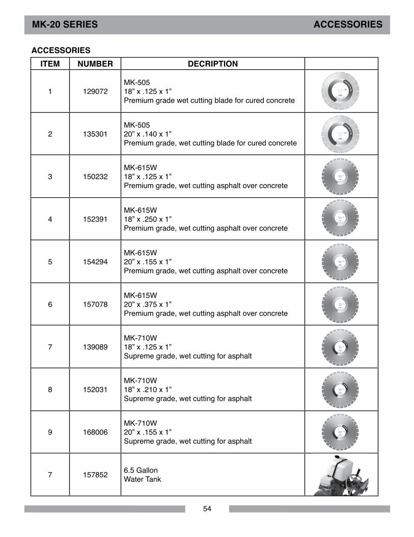
ITEM NUMBER dECRIPTIoN
1 129072MK-50518” x .125 x 1”Premium grade wet cutting blade for cured concrete
2 135301MK-505 20” x .140 x 1”Premium grade, wet cutting blade for cured concrete
3 150232MK-615W 18” x .125 x 1”Premium grade, wet cutting asphalt over concrete
4 152391MK-615W 18” x .250 x 1”Premium grade, wet cutting asphalt over concrete
5 154294MK-615W 20” x .155 x 1”Premium grade, wet cutting asphalt over concrete
6 157078MK-615W 20” x .375 x 1”Premium grade, wet cutting asphalt over concrete
7 139089MK-710W 18” x .125 x 1”Supreme grade, wet cutting for asphalt
8 152031MK-710W 18” x .210 x 1”Supreme grade, wet cutting for asphalt
9 168006MK-710W 20” x .155 x 1”Supreme grade, wet cutting for asphalt
7 157852 6.5 GallonWater Tank
MK-20 SERIES ACCESSoRIES
ACCESSoRIES

55
NoTES

56
MK-20 SERIES oRdERING & RETURN
oRdERING INFoRMATIoNYou may order MK Diamond products through your local MK Diamond distributor or, you may order direct from MK Diamond.
When ordering direct from MK Diamond, please have the following information ready before calling:• The Model Number of the saw• The Serial Number of the saw• Where the saw was purchased and when• The Part Number for the part(s) being ordered• The Part Description for the part(s) being ordered
NoTE: Standard orders are $50.00 or more when ordering direct from MK Diamond. A $6.00 charge will be added to orders having a net billing value under $50.00. A nominal handling fee of $5.00 may apply to some orders.
All parts may be ordered by calling toll free to – 800 421-5830 or 310 539-5221 and asking for Customer Service. For technical questions, call – 800 474-5594.RETURN MATERIAlS PolICY
To expedite the service relative to the return of a product purchased through MK Diamond, please observe the following:
NoTE: When returning all items, they must have been purchased within the previous twelve (12) months.• Have the Model Number of the saw• Have the Serial Number of the saw• Have the location of where the saw was purchased• Have the date when the saw was purchased• Contact Customer Service for approval to return the item(s)• Obtain a Returned Goods Number (RGA) authorizing the return• Follow the packaging instructions in the following section• Ensure the RGA number is on the outside of the returned package• Ensure your item(s) are prepaid to the destinationFor returned items, call toll free to – 800 421-5830 or 310 539-5221 and ask for Customer Service.
PACKAGING INSTRUCTIoNS• Remove the Cutting Head and Support Angle Assembly• Dry the saw before shipping• When packing, include the following: Saw, Diamond Blade, Blade Guard and Support Angle Assembly and Adjustable Cutting Guide (Other Accessories are not required)• Package the unit in its original container or one of comparable size (do not ship the unit partially exposed)• Ensure all parts are secured in the packaging to prevent movingAUTHoRIZEd SERVICE CENTERSFor quicker repair time, you may contact MK Diamond Customer Service, toll free, at 800 421-5830 or 310 539-5221 for the Authorized Service Center closest too you or visit our web site at www.mkdiamond.com. For technical questions, call – 800 474-5594.

57
MK-20 SERIES WARRANTY
CoNTACT:Please contact MK Diamond Products, Inc. Customer Service Department with any questions you might have regarding distributors, parts or service.Telephone: (800) 421-5830Fax: (310) 539-5158E-mail: [email protected] Service Hours: Monday through Friday, 6AM-4PM PST
MK diamond Products, Inc.1315 Storm ParkwayTorrance, CA 90501
© CoPYRIGHT 2015, MK dIAMoNd PRodUCTS, INC. All RIGHTS RESERVEd.The MK Diamond logo is a registered trademark of MK Diamond Products, Inc. and may not be used, reproduced, or altered without written permission. All other trademarks are the property of their re-spective owners and used with permission.
MK Diamond may have patents, patent applications, trade marks, copyrights of other intellectual property right covering this product in this document.
This manual MUST accompany the equipment at all times. This manual is considered a permanent part of the equipment and should remain with the unit if resold.
The information and specifications included in this publication were in effect at the time of approval for printing.
MK DIAMOND PRODUCTS, INC. will guarantee every machine they build, to be free from defects in material and workmanship for (1) one year from date of purchase. The obligation of MK DIAMOND PRODUCTS, INC. under this warranty is limited to the repair or replacement of any parts which, under normal use, prove to be defective in material or workmanship. The parts involved or the unit in question should be returned to MK DIAMOND PRODUCTS, INC. or to a point designated by us, transportation prepaid.
This warranty does not obligate us to bear the cost of labor or transportation charges in connection with replacement or repair of defective parts. Likewise, it shall NOT apply to any unit which has been subjected to misuse, neglect or accident. This warranty does NOT apply to any machine which has been repaired or altered outside our factory.
This warranty does NOT obligate MK DIAMOND PRODUCTS, INC., with respect to items not of our manufacture, such as engines, motors, hydraulics, etc., which are subject to their own guarantees and warranties.
We shall in no event be liable for consequential damages or contingent liabilities arising out of failure of any equipment or parts to operate properly.
MK dIAMoNd PRodUCTS, INC. lIMITEd WARRANTY

58
NoTES

59
NoTES

MK Diamond Products, Inc.1315 Storm ParkwayTorrance, CA 90501
Toll-Free: (800) 421-5830Phone: (310) 539-5221
Fax: (310) 539-5158www.mkdiamond.com
MK-20 SERIES CoNCRETE SAWOWNER’S MANUAL, OPERATING INSTRUCTIONS, &
PARTS LIST