mk-s new model - omron – automação industrial |...
TRANSCRIPT
General-purpose Relays MK-S New Model 1
General-purpose RelaysMK-S New Model
General-purpose Relays Featuring Mechanical Indicator and Lockable Test Button
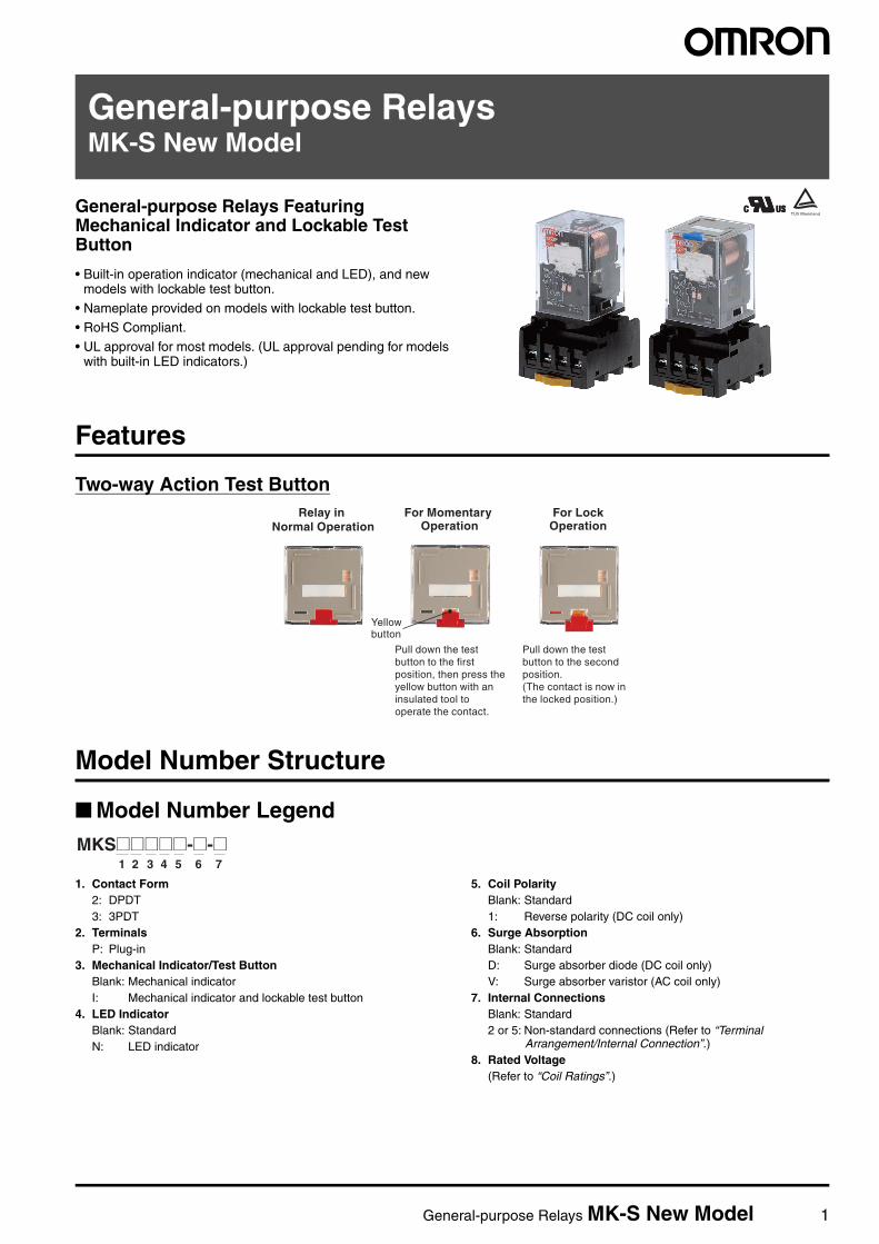
• Built-in operation indicator (mechanical and LED), and new models with lockable test button.
• Nameplate provided on models with lockable test button.
• RoHS Compliant.• UL approval for most models. (UL approval pending for models
with built-in LED indicators.)
Features
Two-way Action Test Button
Model Number Structure
Model Number Legend
1. Contact Form2: DPDT3: 3PDT
2. TerminalsP: Plug-in
3. Mechanical Indicator/Test ButtonBlank: Mechanical indicatorI: Mechanical indicator and lockable test button
4. LED IndicatorBlank: StandardN: LED indicator
5. Coil PolarityBlank: Standard1: Reverse polarity (DC coil only)
6. Surge AbsorptionBlank: StandardD: Surge absorber diode (DC coil only)V: Surge absorber varistor (AC coil only)
7. Internal ConnectionsBlank: Standard2 or 5: Non-standard connections (Refer to “Terminal
Arrangement/Internal Connection”.)8. Rated Voltage
(Refer to “Coil Ratings”.)
Yellowbutton
Relay in Normal Operation
For Momentary Operation
For LockOperation
Pull down the test button to the first position, then press the yellow button with an insulated tool to operate the contact.
Pull down the test button to the second position.(The contact is now in the locked position.)
1 2 3 4 5 6 7
MKS@@@@@-@-@

2 General-purpose Relays MK-S New Model
Ordering Information
List of Models
List of Models (Order Separately)
Type Termi-nals
Contact form Internal connections (See note 3.)
With mechanical indicator With mechanical indicator and lockable test button
Coil ratings
Standard Models
Plug-in DPDT Standard MKS2P MKS2PI AC/DC
Non-standard MKS2P-2 MKS2PI-2
3PDT Standard MKS3P MKS3PI
Non-Standard MKS3P-2 MKS3PI-2
MKS3P-5 MKS3PI-5
Models with LED Indicator (See note 2.)
DPDT Standard MKS2PN(1) MKS2PIN(1) AC/DC
Non-standard MKS2PN(1)-2 MKS2PIN(1)-2
3PDT Standard MKS3PN(1) MKS3PIN(1)
Non-Standard MKS3PN(1)-2 MKS3PIN(1)-2
MKS3PN(1)-5 MKS3PIN(1)-5
Models with Diode(See note 2.)
DPDT Standard MKS2P(1)-D MKS2PI(1)-D DC
Non-standard MKS2P(1)-D-2 MKS2PI(1)-D-2
3PDT Standard MKS3P(1)-D MKS3PI(1)-D
Non-Standard MKS3P(1)-D-2 MKS3PI(1)-D-2
MKS3P(1)-D-5 MKS3PI(1)-D-5
Models with LED Indicator and Diode
DPDT Standard MKS2PN-D MKS2PIN-D DC
Non-standard MKS2PN-D-2 MKS2PIN-D-2
3PDT Standard MKS3PN-D MKS3PIN-D
Non-Standard MKS3PN-D-2 MKS3PIN-D-2
MKS3PN-D-5 MKS3PIN-D-5
Models with Varistor
DPDT Standard MKS2P-V MKS2PI-V AC
Non-standard MKS2P-V-2 MKS2PI-V-2
3PDT Standard MKS3P-V MKS3PI-V
Non-Standard MKS3P-V-2 MKS3PI-V-2
MKS3P-V-5 MKS3PI-V-5
Models with LED Indicator and Varistor
DPDT Standard MKS2PN-V MKS2PIN-V AC
Non-standard MKS2PN-V-2 MKS2PIN-V-2
3PDT Standard MKS3PN-V MKS3PIN-V
Non-Standard MKS3PN-V-2 MKS3PIN-V-2
MKS3PN-V-5 MKS3PIN-V-5
Item Type Model
Track-mounted Socket 8-pin PF083A-E
11-pin PF113A-E
8-pin PF083A-D
11-pin PF113A-D
Hold-down Clip (For PF083A-E and PF113A-E)
PFC-A1
Rated voltage
Note: 1. When ordering, add the rated voltage to the model number. Rated voltages are given in the coil ratings table in the specifications. Example: MKS3P 24 VDC
2. The DC coil comes in two types: standard coil polarity and reverse coil polarity. Refer to Terminal Arrangement and Internal Connections.
Example: MKS2PIN1-2 24 VDC
3. Refer to Terminal Arrangement and Internal Connections for non-standard internal connections.Reverse coil polarity

General-purpose Relays MK-S New Model 3
Specifications
Ratings
Coil Ratings
Note: 1. The rated current and coil resistance are measured at a coil temperature of 23°C with tolerances of +15%/−20% for AC rated current and±15% for DC coil resistance.
2. Performance characteristic data are measured at a coil temperature of 23°C.3. The maximum voltage is one that is applicable instantaneously to the Relay coil at 23°C and not continuously.4. For DC-operated Relays with the LED indicator built-in, add an LED current of approx. 5 mA to the rated current.
Contact Ratings
Rated voltage Rated current Coil resistance Must operate voltage
Must release voltage
Max. voltage Power consumption50 Hz 60 Hz
AC 6 V 443 mA 385 mA 3.1 Ω 80% max. of rated voltage
30% min. of rated voltage at 60 Hz25% min. of rated voltage at 50 Hz
110% of rated volt-age
Approx. 2.3 VAat 60 HzApprox. 2.7 VAat 50 Hz
12 V 221 mA 193 mA 13.7 Ω24 V 110 mA 96.3 mA 48.4 Ω100 V 26.6 mA 23.1 mA 760 Ω110 V 24.2 mA 21.0 mA 932 Ω200 V 13.3 mA 11.6 mA 3,160 Ω220 V 12.1 mA 10.5 mA 3,550 Ω230 V 10.0 mA 11.5 mA 4,250 Ω240 V 11.0 mA 9.6 mA 4,480 Ω
DC 6 V 224 mA 26.7 Ω 15% min. of rated voltage
Approx. 1.4 W
12 V 112 mA 107 Ω24 V 55.8 mA 430 Ω48 V 28.1 mA 1,710 Ω100 V 13.5 mA 7,390 Ω110 V 12.3 mA 8,960 Ω
Load Resistive load(cosφ = 1)
Inductive load(cosφ = 0.4)
Contact mechanism Single
Contact material AgSnIn
Rated load NO 10 A, 250 VAC10A, 30 VDC
7 A, 250 VAC
NC 5 A, 250 VAC5 A, 30 VDC
Rated carry current 10 A
Max. switching voltage 250 VAC, 250 VDC
Max. switching current 10 A
Max. switching power NO 2,500 VA/300 W
NC 1,250 VA/150 W

4 General-purpose Relays MK-S New Model
Characteristics
Note: 1. The values given above are initial values.2. P level: λ60 = 0.1 × 10⁻⁶/operation3. Ambient temperature of models with LED indicator is −25 to 60°C.
Approved StandardsUL508 (File No. E41515)
CSA Standard: CSA Certification by
: CSA C22.2 No. 14Note: Applications have been submitted for UL and CSA certification
for models with built-in LED indicators.
IEC Standard/TUV Certification: IEC61810-1 (Certification No. R50104853)
Note: When Relays are mounted on the PF083A-E or PF113A-E, the maximum carrying current is 9 A.
Engineering Data Reference Data
Contact resistance 100 mΩ max.
Operate time AC: 20 ms max. DC: 30 ms max.
Release time 20 ms max.(40 ms max. for built-in Diode Relays)
Max. operating frequency Mechanical: 18,000 operations/hElectrical: 1,800 operations/h (under rated load)
Insulation resistance 100 MΩ min. (at 500 VDC)
Dielectric strength 2,500 VAC 50/60 Hz for 1 min between coil and contacts1,000 VAC 50/60 Hz for 1 min between contacts of same polarity and terminals of the same polarity2,500 VAC 50/60 Hz for 1 min between current-carrying parts, non-current-carrying parts, and opposite polarity
Insulation method Basic insulation
Impulse withstand voltage 4.5 kV between coil and contacts (with 1.2 × 50 µs impulse wave)3.0 kV between contacts of different polarity (with 1.2 × 50 µs impulse wave)
Pollution degree 3
Rated insulation voltage 250 V
Vibration resistance Destruction: 10 to 55 to 10 Hz, 0.75-mm single amplitude (1.5-mm double amplitude)Malfunction: 10 to 55 to 10 Hz, 0.5-mm single amplitude (1.0-mm double amplitude)
Shock resistance Destruction: 1,000 m/s2 (approx. 100 G)Malfunction: 100 m/s2 (approx. 10 G)
Endurance Mechanical: 5,000,000 operations min. (at 18,000 operations/h under rated load)Electrical: 100,000 operations h. (at 1,800 operations/h under rated load)
Failure rate P level (reference value) 10 mA at 1 VDC
Ambient temperature Operating: –40 to 60°C (with no icing or condensation)
Ambient humidity Operating: 5% to 85%
Weight Approx. 90 g
Coil ratings Contact ratings Operations6 to 110 VDC 6 to 240 VAC
N.O.contact
10 A, 250 V AC 50/60 Hz (Resistive) 10 A, 30 V DC (Resistive) 7 A, 250 V AC 50/60 Hz (General Use)
6,000
N.C.contact
5 A, 250 V AC 50/60 Hz (Resistive) 5 A, 30 V DC (Resistive) 7 A, 250 V AC 50/60 Hz (General Use)
6,000 Coil ratings Contact ratings Operations6, 12, 24, 48, 100, 110 VDC 6, 12, 24, 100, 110, 200, 220, 240 VAC
N.O.contact
10 A, 250 V AC 50/60 Hz (Resistive) 10 A, 30 V DC (Resistive) 7 A, 250 V AC 50/60 Hz (General Use)
100,000
N.C.contact
5 A, 250 V AC 50/60 Hz (Resistive) 5 A, 30 V DC (Resistive) 7 A, 250 V AC 50/60 Hz (General Use)
100,000
Maximum Switching Power Rated Carry Current vs. Ambient Rated Temperature
Note: The lower limit of the ambient operating temperature for models with built-in operation indicators is −25°C.
100
50
30
10
5
3
110 30 50 100 300 500 1.000
Switching voltage (V)
Sw
itchi
ng c
urre
nt (
A)
AC resistive load with NO contact
AC inductive load (cosφ = 0.4)
DC resistive load with NO contact
AC resistive load with NC contact
DC resistive load with
NC contact
−40 −20 0 20 40 60 80
10
5
0
UL derating curve
Rat
ed c
arry
cur
rent
(A
)
Ambient temperature (°C)

General-purpose Relays MK-S New Model 5
DimensionsNote: All units are in millimeters unless otherwise indicated.
Models without Test Button Models with Lockable Test Button
SocketsSee below for Socket dimensions.
Note: Use the Surface-mounting Sockets (i.e., finger-protection models) with "-E" at the end of the model number. When using the PF083A andPF113A, be sure not to exceed the Socket's maximum carry current of 5 A. Using at a current exceeding 5 A may lead to burning. Roundterminals cannot be used for finger-protection models. Use Y-shaped terminals.
52.5 max.34.5 max.
34.5 max.
0.834.5 max.
34.5 max.
52.5 max.0.8
Socket Surface-mounting Socket (for track or screw mounting)
Finger-protection models ---
Maximum carry current 10 A 5 A
2 poles PF083A-E PF083A-D PF083A
3 poles PF113A-E PF113A-E-D PF113A
7
33
4
35.4
23.5
7
34
4
35.4
23.5
33±0.2 33±0.2
4
PF083A-E (Conforming to EN 50022)
Mounting Holes
Terminal ArrangementPF113A-E (Conforming to EN 50022)
52 max.
Eight, M3.5 × 7 sems
41 max.21 max.
Two, M4 or two 4.5-dia. holes Two, M4 or two 4.5-dia. holes
Eleven, M3.5 × 7 sems
52 max.
42.8 max.31 max.
Mounting Holes
Terminal Arrangement

6 General-purpose Relays MK-S New Model
Hold-down Clips
Mounting Tracks
Mounting Height with Sockets
Surface-mounting Sockets
Note: PF083A(-E) and PF113A(-E) allow either track or screw mounting.
PF083A-D
Terminal Arrangement
Mounting Holes
Eight, M4 screws
Two, M4 or two 4.5-dia. hole
4
5.5
65
27
8
5
21
22
412
111
2A1
7A2
314
624
38
8
30
PF113A-D
4
5.5
65
27
1
6
11
21
2A111
31
522
724
10A2
934
314
412
832
38
8
30
Terminal Arrangement
Mounting Holes
Two, M4 or two 4.5-dia. hole
Eight, M4 screws
PFC-A1
4.6
6260.8
4.56
(2 pieces per set)
4.5
15 25 25 25 25 *10 101000 (500)*
7.3±0.15
35±0.3 27±0.15
1
4.5
15 25 25 25 25 1510 101000±4
35±0.3 27 24
16
29.2
1 1.5
* This dimension applies to the PFP-50N Mounting Track. * A total of twelve 25 × 4.5 elliptic holes is provided with six holes cut from each track end at a pitch of 10 mm.
PFP-100N, PFP-50N (Conforming to EN 50022)
PFP-100N2 (Conforming to EN 50022)
74.384.3
PF083A(-E) PF113A(-E)
77.8 (See note.)
87.8 (See note.)
Two poles
Three poles

General-purpose Relays MK-S New Model 7
Terminal Arrangement/Internal ConnectionStandard Models(AC/DC Coil)
MKS2P(I) MKS2P(I)-2 MKS3P(I) MKS3P(I)-2 MKS3P(I)-5
Models with LED Indicator(AC Coil)
MKS2P(I)N MKS2P(I)N-2 MKS3P(I)N MKS3P(I)N-2 MKS3P(I)N-5
Models with Diode(DC Coil: Standard Polarity)
MKS2P(I)N MKS2P(I)N-2 MKS3P(I)N MKS3P(I)N-2 MKS3P(I)N-5
Models with LED Indicator and DIode(DC Coil: Reverse Polarity)
MKS2P(I)N1 MKS2P(I)N1-2 MKS3P(I)N1 MKS3P(I)N1-2 MKS3P(I)N1-5
Standard Models(DC Coil:Standard Polarity)
MKS2P(I)-D MKS2P(I)-D-2 MKS3P(I)-D MKS3P(I)-D-2 MKS3P(I)-D-5
Models with Diode(DC Coil:Reverse Polarity)
MKS2P(I)1-D MKS2P(I)1-D-2 MKS3P(I)1-D MKS3P(I)1-D-2 MKS3P(I)1-D-5
Models with LED indicator(DC Coil)
MKS2P(I)N-D MKS2P(I)N-D-2 MKS3P(I)N-D MKS3P(I)N-D-2 MKS3P(I)N-D-5
(Bottom View)
1
2
3
4 5
6
7
8 8
63
1
2 7
4 5
12
3
45 6 7
8
1011
9 9
1110
8765
4
3
21
9
1110
8765
4
3
21
8
7
6
54
3
2
1
54
72
1
3 6
81
2
3
45 6 7
8
1011
9 9
1110
8765
4
3
21
9
1110
8765
4
3
21
8
7
6
54
3
2
1
54
72
1
3 6
81
2
3
45 6 7
8
1011
9 9
1110
8765
4
3
21
9
1110
8765
4
3
21
8
7
6
54
3
2
1
54
72
1
3 6
81
2
3
45 6 7
8
1011
9 9
1110
8765
4
3
21
9
1110
8765
4
3
21
8
7
6
54
3
2
1
54
72
1
3 6
81
2
3
45 6 7
8
1011
9 9
1110
8765
4
3
21
9
1110
8765
4
3
21
8
7
6
54
3
2
1
54
72
1
3 6
81
2
3
45 6 7
8
1011
9 9
1110
8765
4
3
21
9
1110
8765
4
3
21
1
2
3
4 5
6
7
8 8
63
1
2 7
4 5
12
3
45 6 7
8
1011
9 9
1110
8765
4
3
21
9
1110
8765
4
3
21

8 General-purpose Relays MK-S New Model
Safety Precautions
Safety Precautions for Correct Use
InstallationMount the MK-S with the marking at the bottom.
HandlingCheck the coil polarity of models with built-in diodes and wire them correctly (DC operation coil).
Test ButtonDo not use the test button for any purpose other than testing. Be sure not to touch the test button accidentally as this will turn the contacts ON. Before using the test button, confirm that circuits, the load, and any other connected item will operate safely.
Check that the test button is released before turning ON relay circuits.
If the test button is pulled out too forcefully, it may bypass the momentary testing position and go straight into the locked position.
Use an insulated tool when you operate the test button.
Models with test buttons or LED indicators fulfill the requirements for reinforced insulation between live parts and the front of cover only when the Relay is in a complete condition, i.e. with the nameplate, nameplate frame, test button, and slider in place. If any of these parts are removed, only the requirements for basic insulation are fulfilled.
Models with Varistor(AC Coil)
MKS2P(I)-V MKS2P(I)-V-2 MKS3P(I)-V MKS3P(I)-V-2 MKS3P(I)-V-5
Models with LED indicator and Varistor(AC Coil)
MKS2P(I)N-V MKS2P(I)N-V-2 MKS3P(I)N-V MKS3P(I)N-V-2 MKS3P(I)N-V-5
8
7
6
54
3
2
1
54
72
1
3 6
81
2
3
45 6 7
8
1011
9 9
1110
8765
4
3
21
9
1110
8765
4
3
2
1
1
2
3
4 5
6
7
8 8
63
1
2 7
4 5
9
1110
8765
4
3
21 1
2
3
45 6 7
8
1011
9
12
3
45 6 7
8
1011
9

Terms and Conditions of Sale1. Offer; Acceptance. These terms and conditions (these "Terms") are deemed
part of all quotes, agreements, purchase orders, acknowledgments, price lists,catalogs, manuals, brochures and other documents, whether electronic or inwriting, relating to the sale of products or services (collectively, the "Products")by Omron Electronics LLC and its subsidiary companies (“Omron”). Omronobjects to any terms or conditions proposed in Buyer’s purchase order or otherdocuments which are inconsistent with, or in addition to, these Terms.
2. Prices; Payment Terms. All prices stated are current, subject to change with-out notice by Omron. Omron reserves the right to increase or decrease priceson any unshipped portions of outstanding orders. Payments for Products aredue net 30 days unless otherwise stated in the invoice.
3. Discounts. Cash discounts, if any, will apply only on the net amount of invoicessent to Buyer after deducting transportation charges, taxes and duties, and willbe allowed only if (i) the invoice is paid according to Omron’s payment termsand (ii) Buyer has no past due amounts.
4. Interest. Omron, at its option, may charge Buyer 1-1/2% interest per month orthe maximum legal rate, whichever is less, on any balance not paid within thestated terms.
5. Orders. Omron will accept no order less than $200 net billing. 6. Governmental Approvals. Buyer shall be responsible for, and shall bear all
costs involved in, obtaining any government approvals required for the impor-tation or sale of the Products.
7. Taxes. All taxes, duties and other governmental charges (other than generalreal property and income taxes), including any interest or penalties thereon,imposed directly or indirectly on Omron or required to be collected directly orindirectly by Omron for the manufacture, production, sale, delivery, importa-tion, consumption or use of the Products sold hereunder (including customsduties and sales, excise, use, turnover and license taxes) shall be charged toand remitted by Buyer to Omron.
8. Financial. If the financial position of Buyer at any time becomes unsatisfactoryto Omron, Omron reserves the right to stop shipments or require satisfactorysecurity or payment in advance. If Buyer fails to make payment or otherwisecomply with these Terms or any related agreement, Omron may (without liabil-ity and in addition to other remedies) cancel any unshipped portion of Prod-ucts sold hereunder and stop any Products in transit until Buyer pays allamounts, including amounts payable hereunder, whether or not then due,which are owing to it by Buyer. Buyer shall in any event remain liable for allunpaid accounts.
9. Cancellation; Etc. Orders are not subject to rescheduling or cancellationunless Buyer indemnifies Omron against all related costs or expenses.
10. Force Majeure. Omron shall not be liable for any delay or failure in deliveryresulting from causes beyond its control, including earthquakes, fires, floods,strikes or other labor disputes, shortage of labor or materials, accidents tomachinery, acts of sabotage, riots, delay in or lack of transportation or therequirements of any government authority.
11. Shipping; Delivery. Unless otherwise expressly agreed in writing by Omron:a. Shipments shall be by a carrier selected by Omron; Omron will not drop ship
except in “break down” situations.b. Such carrier shall act as the agent of Buyer and delivery to such carrier shall
constitute delivery to Buyer;c. All sales and shipments of Products shall be FOB shipping point (unless oth-
erwise stated in writing by Omron), at which point title and risk of loss shallpass from Omron to Buyer; provided that Omron shall retain a security inter-est in the Products until the full purchase price is paid;
d. Delivery and shipping dates are estimates only; ande. Omron will package Products as it deems proper for protection against nor-
mal handling and extra charges apply to special conditions.12. Claims. Any claim by Buyer against Omron for shortage or damage to the
Products occurring before delivery to the carrier must be presented in writingto Omron within 30 days of receipt of shipment and include the original trans-portation bill signed by the carrier noting that the carrier received the Productsfrom Omron in the condition claimed.
13. Warranties. (a) Exclusive Warranty. Omron’s exclusive warranty is that theProducts will be free from defects in materials and workmanship for a period oftwelve months from the date of sale by Omron (or such other period expressedin writing by Omron). Omron disclaims all other warranties, express or implied.(b) Limitations. OMRON MAKES NO WARRANTY OR REPRESENTATION,EXPRESS OR IMPLIED, ABOUT NON-INFRINGEMENT, MERCHANTABIL-
ITY OR FITNESS FOR A PARTICULAR PURPOSE OF THE PRODUCTS.BUYER ACKNOWLEDGES THAT IT ALONE HAS DETERMINED THAT THEPRODUCTS WILL SUITABLY MEET THE REQUIREMENTS OF THEIRINTENDED USE. Omron further disclaims all warranties and responsibility ofany type for claims or expenses based on infringement by the Products or oth-erwise of any intellectual property right. (c) Buyer Remedy. Omron’s sole obli-gation hereunder shall be, at Omron’s election, to (i) replace (in the formoriginally shipped with Buyer responsible for labor charges for removal orreplacement thereof) the non-complying Product, (ii) repair the non-complyingProduct, or (iii) repay or credit Buyer an amount equal to the purchase price ofthe non-complying Product; provided that in no event shall Omron be responsi-ble for warranty, repair, indemnity or any other claims or expenses regardingthe Products unless Omron’s analysis confirms that the Products were prop-erly handled, stored, installed and maintained and not subject to contamina-tion, abuse, misuse or inappropriate modification. Return of any Products byBuyer must be approved in writing by Omron before shipment. Omron Compa-nies shall not be liable for the suitability or unsuitability or the results from theuse of Products in combination with any electrical or electronic components,circuits, system assemblies or any other materials or substances or environ-ments. Any advice, recommendations or information given orally or in writing,are not to be construed as an amendment or addition to the above warranty.See http://www.omron247.com or contact your Omron representative for pub-lished information.
14. Limitation on Liability; Etc. OMRON COMPANIES SHALL NOT BE LIABLEFOR SPECIAL, INDIRECT, INCIDENTAL, OR CONSEQUENTIAL DAMAGES,LOSS OF PROFITS OR PRODUCTION OR COMMERCIAL LOSS IN ANYWAY CONNECTED WITH THE PRODUCTS, WHETHER SUCH CLAIM ISBASED IN CONTRACT, WARRANTY, NEGLIGENCE OR STRICT LIABILITY.Further, in no event shall liability of Omron Companies exceed the individualprice of the Product on which liability is asserted.
15. Indemnities. Buyer shall indemnify and hold harmless Omron Companies andtheir employees from and against all liabilities, losses, claims, costs andexpenses (including attorney's fees and expenses) related to any claim, inves-tigation, litigation or proceeding (whether or not Omron is a party) which arisesor is alleged to arise from Buyer's acts or omissions under these Terms or inany way with respect to the Products. Without limiting the foregoing, Buyer (atits own expense) shall indemnify and hold harmless Omron and defend or set-tle any action brought against such Companies to the extent based on a claimthat any Product made to Buyer specifications infringed intellectual propertyrights of another party.
16. Property; Confidentiality. Any intellectual property in the Products is the exclu-sive property of Omron Companies and Buyer shall not attempt to duplicate itin any way without the written permission of Omron. Notwithstanding anycharges to Buyer for engineering or tooling, all engineering and tooling shallremain the exclusive property of Omron. All information and materials suppliedby Omron to Buyer relating to the Products are confidential and proprietary,and Buyer shall limit distribution thereof to its trusted employees and strictlyprevent disclosure to any third party.
17. Export Controls. Buyer shall comply with all applicable laws, regulations andlicenses regarding (i) export of products or information; (iii) sale of products to“forbidden” or other proscribed persons; and (ii) disclosure to non-citizens ofregulated technology or information.
18. Miscellaneous. (a) Waiver. No failure or delay by Omron in exercising any rightand no course of dealing between Buyer and Omron shall operate as a waiverof rights by Omron. (b) Assignment. Buyer may not assign its rights hereunderwithout Omron's written consent. (c) Law. These Terms are governed by thelaw of the jurisdiction of the home office of the Omron company from whichBuyer is purchasing the Products (without regard to conflict of law princi-ples). (d) Amendment. These Terms constitute the entire agreement betweenBuyer and Omron relating to the Products, and no provision may be changedor waived unless in writing signed by the parties. (e) Severability. If any provi-sion hereof is rendered ineffective or invalid, such provision shall not invalidateany other provision. (f) Setoff. Buyer shall have no right to set off any amountsagainst the amount owing in respect of this invoice. (g) Definitions. As usedherein, “including” means “including without limitation”; and “Omron Compa-nies” (or similar words) mean Omron Corporation and any direct or indirectsubsidiary or affiliate thereof.
Certain Precautions on Specifications and Use1. Suitability of Use. Omron Companies shall not be responsible for conformity
with any standards, codes or regulations which apply to the combination of theProduct in the Buyer’s application or use of the Product. At Buyer’s request,Omron will provide applicable third party certification documents identifyingratings and limitations of use which apply to the Product. This information byitself is not sufficient for a complete determination of the suitability of the Prod-uct in combination with the end product, machine, system, or other applicationor use. Buyer shall be solely responsible for determining appropriateness ofthe particular Product with respect to Buyer’s application, product or system.Buyer shall take application responsibility in all cases but the following is anon-exhaustive list of applications for which particular attention must be given:(i) Outdoor use, uses involving potential chemical contamination or electricalinterference, or conditions or uses not described in this document.(ii) Use in consumer products or any use in significant quantities. (iii) Energy control systems, combustion systems, railroad systems, aviationsystems, medical equipment, amusement machines, vehicles, safety equip-ment, and installations subject to separate industry or government regulations. (iv) Systems, machines and equipment that could present a risk to life or prop-erty. Please know and observe all prohibitions of use applicable to this Prod-uct. NEVER USE THE PRODUCT FOR AN APPLICATION INVOLVING SERIOUSRISK TO LIFE OR PROPERTY OR IN LARGE QUANTITIES WITHOUTENSURING THAT THE SYSTEM AS A WHOLE HAS BEEN DESIGNED TO
ADDRESS THE RISKS, AND THAT THE OMRON’S PRODUCT IS PROP-ERLY RATED AND INSTALLED FOR THE INTENDED USE WITHIN THEOVERALL EQUIPMENT OR SYSTEM.
2. Programmable Products. Omron Companies shall not be responsible for theuser’s programming of a programmable Product, or any consequence thereof.
3. Performance Data. Data presented in Omron Company websites, catalogsand other materials is provided as a guide for the user in determining suitabil-ity and does not constitute a warranty. It may represent the result of Omron’stest conditions, and the user must correlate it to actual application require-ments. Actual performance is subject to the Omron’s Warranty and Limitationsof Liability.
4. Change in Specifications. Product specifications and accessories may bechanged at any time based on improvements and other reasons. It is our prac-tice to change part numbers when published ratings or features are changed,or when significant construction changes are made. However, some specifica-tions of the Product may be changed without any notice. When in doubt, spe-cial part numbers may be assigned to fix or establish key specifications foryour application. Please consult with your Omron’s representative at any timeto confirm actual specifications of purchased Product.
5. Errors and Omissions. Information presented by Omron Companies has beenchecked and is believed to be accurate; however, no responsibility is assumedfor clerical, typographical or proofreading errors or omissions.

Note: Specifications are subject to change. © 2008 Omron Electronics LLC Printed in U.S.A.
OMRON ELECTRONICS LLC • THE AMERICAS HEADQUARTERS
Schaumburg, IL USA • 847.843.7900 • 800.556.6766 • www.omron247.com
OMRON CANADA, INC. • HEAD OFFICEToronto, ON, Canada • 416.286.6465 • 866.986.6766 • www.omron.ca
OMRON ELETRÔNICA DO BRASIL LTDA • HEAD OFFICESão Paulo, SP, Brasil • 55.11.2101.6300 • www.omron.com.br
OMRON ELECTRONICS MEXICO SA DE CV • HEAD OFFICEApodaca, N.L. • 52.811.156.99.10 • [email protected]
OMRON ARGENTINA • SALES OFFICECono Sur • 54.11.4787.1129
OMRON CHILE • SALES OFFICESantiago 56.2206.4592
OTHER OMRON LATIN AMERICA SALES56.2206.4592
J168-E1-01