mk7 manual - autoflame.org. flame safeguard and... · figure 1.1.i gas valve proving diagram figure...
TRANSCRIPT

Mk7 Manual: M.M. Flame Safeguard
and Operation


Mk7 Manual:
M.M. Flame Safeguard and Operation
Issued by: AUTOFLAME ENGINEERING LTD
Unit 1-2, Concorde Business Centre Airport Industrial Estate, Wireless Road
Biggin Hill, Kent TN16 3YN
Tel: +44 (0)845 872 2000 Fax: +44 (0)845 872 2010
Email: [email protected] Website: http://www.autoflame.com/
Registered Holder: Company: Department:
This manual and all the information contained herein is copyright of
Autoflame Engineering Ltd. It may not be copied in the whole or part without the consent of the Managing Director.
Autoflame Engineering Ltd’s policy is one of continuous improvement in both design and manufacture. We therefore reserve the right to amend
specifications and/pr data without prior notice. All details contained in this manual are correct at the time of going to print.

Important Notes
A knowledge of combustion related procedures and commissioning is essential before embarking work on any of the M.M./E.G.A. systems. This is for safety reasons and effective use of the M.M./ E.G.A. system. Hands on training is required. For details on schedules and fees relating to group training courses and individual instruction, please contact the Autoflame Engineering Ltd. offices at the address listed on the front.
Short Form - General Terms and Conditions
A full statement of our business terms and conditions are printed on the reverse of all invoices. A copy of these can be issued upon application, if requested in writing.
The System equipment and control concepts referred to in this Manual MUST be installed, commissioned and applied by personnel skilled in the various technical disciplines that are inherent to the Autoflame product range, i.e. combustion, electrical and control.
The sale of Autoflame’s systems and equipment referred to in this Manual assume that the dealer, purchaser and installer has the necessary skills at his disposal. i.e. A high degree of combustion engineering experience, and a thorough understanding of the local electrical codes of practice concerning boilers, burners and their ancillary systems and equipment.
Autoflame’s warranty from point of sale is two years on all electronic systems and components. One year on all mechanical systems, components and sensors.
The warranty assumes that all equipment supplied will be used for the purpose that it was intended and in strict compliance with our technical recommendations. Auto-flame’s warranty and guarantee is limited strictly to product build quality, and design. Excluded absolutely are any claims arising from misapplication, incorrect installation and/or incorrect commissioning.

Contents 1 SENSORS ............................................................................................................... 1
1.1 Gas Valve Proving .................................................................................................................. 1
1.1.1 Gas Pressure Sensor ....................................................................................................... 2
1.1.2 Oil Pressure Sensor ......................................................................................................... 3
1.1.3 Commissioning Valve Proving ......................................................................................... 4
1.2 Air Pressure Proving ............................................................................................................... 6
1.2.1 Air Pressure Sensor ......................................................................................................... 7
1.2.2 Air Pressure Tapped Fitting ............................................................................................. 8
1.3 Load Detectors ........................................................................................................................ 9
1.3.1 Steam Pressure Sensor .................................................................................................... 9
1.3.2 Water Temperature Sensor .......................................................................................... 10
1.3.3 Outside Temperature Compensation ........................................................................... 11
2 FLAME SAFEGUARD .............................................................................................. 13
2.1 Burner Control Sequence Diagram ...................................................................................... 13
2.1.1 Interrupted Pilot Gas .................................................................................................... 14
2.1.2 Interrupted Oil ............................................................................................................. 15
2.1.3 Intermittent Pilot ........................................................................................................... 16
2.2 Flame Scanner Types ........................................................................................................... 17
2.2.1 IR Self-Check End View Scanner .................................................................................. 17
2.2.2 Self-Check UV Scanner ................................................................................................ 18
2.2.3 Self-Check Side View UV Scanner .............................................................................. 19
2.2.4 Standard European Side Viewing UV Scanner ............................................................ 20
2.2.5 Standard North American UV Scanner – End Viewing .............................................. 21
2.2.5 Swivel Mount Assembly ............................................................................................... 23
2.3 Selection Of UV Scanner Types ........................................................................................... 23
2.3.1 Normal Sensitivity ........................................................................................................ 23
2.3.2 High Sensitivity ............................................................................................................ 24
2.3.3 UV Installation ............................................................................................................. 24
2.3.4 UV Self Adaptive Pulse Width Modulation .................................................................. 25
2.3.5 Dual UV and IR Scanner Operation (AGA) ................................................................ 26
2.4 Flame Detection Using An External Flame Switch ................................................................ 27
2.4.1 Flame Switch Configuration ......................................................................................... 27
3 HAND, LOW FLAME HOLD AND AUTO .................................................................. 28
3.1 Hand Operation .................................................................................................................. 28
3.2 Low Flame Hold ................................................................................................................... 28

3.3 Auto Operation ................................................................................................................... 28
4 PID CONTROL ....................................................................................................... 29
4.1 Introduction.......................................................................................................................... 29
4.2 Proportional Band ............................................................................................................... 29
4.3 Integral Control ................................................................................................................... 30
4.4 Derivative Control ................................................................................................................ 31
4.5 PID Controller Considerations ............................................................................................. 32
4.5.1 Super “I” ..................................................................................................................... 32
5 INTELLIGENT BOILER SEQUENCING ....................................................................... 34
5.1 Overview of Sequencing ..................................................................................................... 34
5.1.1 Features and Benefits ................................................................................................... 34
5.1.2 Hot Water Boilers Sequencing ..................................................................................... 34
5.1.3 Steam Boilers Sequencing ........................................................................................... 34
5.2 Sequencing Options and Parameters .................................................................................. 36
5.3 Guide to Commissioning Sequencing .................................................................................. 40
5.3.1 Implementing Hot Water Sequencing .......................................................................... 41
5.3.2 Implementing Steam Sequencing ................................................................................. 41
5.4 Electrical Schematics ............................................................................................................ 42
5.4.1 Sequencing Connection Diagram ................................................................................ 42
5.4.2 DTI Sequencing Connection Diagram .......................................................................... 43
5.5 IBS Examples ....................................................................................................................... 44
5.5.1 Hot Water Sequencing Example ................................................................................. 44
5.5.2 Single/Twin Burner Example ....................................................................................... 45
5.5.3 Example Of IBS Communications ................................................................................ 46
6 TWIN BURNER OPERATION .................................................................................. 47
6.1 Twin Burner Commissioning ................................................................................................. 47
6.2 Normal Operation ............................................................................................................... 47
6.3 Twin Burner with Water Level Control ................................................................................. 48
6.3 Twin Burner with Single E.G.A. ............................................................................................ 49
6.5 Connection Between Mk7 MM Modules for Twin Burner .................................................... 50
7 APPLICATION POSSIBILITIES ................................................................................. 51
7.1 Pressure Jet/Gun Type Burners ............................................................................................ 51
7.2 Mk7 M.M. System with EGA and Water Level Control .................................................... 53
7.3 Changeover on the Fly ..................................................................................................... 54
7.3.1 Hardware Requirements ........................................................................................... 54
7.3.2 Operational Components ..........................................................................................54
7.3.3 Important Options/Parameters to Set ........................................................................55

7.3.4 COF Operation ......................................................................................................... 55
7.3.5 COF Lockout Messages ............................................................................................ 56
7.4 No Pre-purge .................................................................................................................... 57
7.4.1 Operation ................................................................................................................. 57
7.5 Continuous Pilot ................................................................................................................ 58
7.5.1 Operation ................................................................................................................. 58


1 SENSORS
1.1 Gas Valve Proving
Figure 1.1.i Gas Valve Proving Diagram
Figure 1.1.i shows the sequence for the Autoflame gas valve proving.
1 Sensors
July 2014 Mk7 Manual: M.M. Flame Safeguard and Operation Page 1
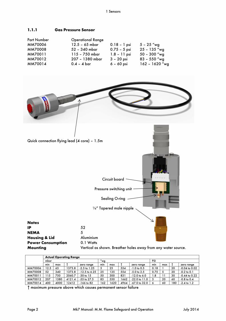
1.1.1 Gas Pressure Sensor
Part Number Operational Range MM70006 12.5 – 65 mbar 0.18 – 1 psi 5 – 25 “wg MM70008 52 – 340 mbar 0.75 – 5 psi 25 – 135 “wg MM70011 115 – 750 mbar 1.8 – 11 psi 50 – 300 “wg MM70012 207 – 1380 mbar 3 – 20 psi 83 – 550 “wg MM70014 0.4 – 4 bar 6 – 60 psi 162 – 1620 “wg
Quick connection flying lead (4 core) – 1.5m
Circuit board
Pressure switching unit
Sealing O-ring
¼” Tapered male nipple Notes IP 52 NEMA 5 Housing & Lid Aluminium Power Consumption 0.1 Watts Mounting Vertical as shown. Breather holes away from any water source.
Actual Operating Range mbar “wg PSImin max † zero range min max † zero range min max † zero range
MM70006 12.5 65 1373.8 -2.5 to 1.25 5 25 554 -1.0 to 0.5 0.18 1 20 -0.04 to 0.02MM70008 52 340 1373.8 -12.5 to 6.25 25 135 554 -5.0 to 2.5 0.75 5 20 -0.2 to 0.1MM70011 115 750 2060.7 -30 to 15 50 300 831 -12.0 to 6.0 1.8 11 30 -0.44 to 0.22MM70012 207 1380 4121.4 -55 to 27.5 83 550 1662 -22.0 to 11.0 3 20 60 -0.8 to 0.4MM70014 400 4000 12412 -166 to 82 162 1620 4964 -67.0 to 32.0 6 60 180 -2.4 to 1.2
† maximum pressure above which causes permanent sensor failure
1 Sensors
Page 2 Mk7 Manual: M.M. Flame Safeguard and Operation July 2014
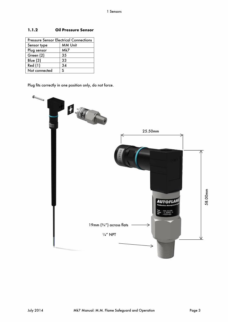
1.1.2 Oil Pressure Sensor
Pressure Sensor Electrical Connections Sensor type MM Unit Plug sensor Mk7 Green (2) 35 Blue (3) 33 Red (1) 34 Not connected S
Plug fits correctly in one position only, do not force.
19mm (¾”) across flats
¼” NPT
58
.00
mm
25.50mm
1 Sensors
July 2014 Mk7 Manual: M.M. Flame Safeguard and Operation Page 3

NOTE:
MAXIMUM 2.5mm FLAT BLADE SCREW DRIVER FOR ELECTRICAL CONNECTIONS I.P. 65 NEMA 4 TORQUE SETTING MAX. 25Nm DO NOT USE CASE TO TIGHTEN PRESSURE CONNECTION. O-RING MATERIAL VITON MAX. STORAGE TEMPERATURE -25 TO +85 DEG. C (-13 TO 185 DEG. F) MAX. OPERATING TEMPERATURE -25 TO +85 DEG. C (-13 TO 185 DEG. F) MEDIA TEMPERAURE -25 TO +125 DEG. C (-13 TO 257 DEG. F) OPERATING RANGE 0 TO 600 PSI / 0 TO 40 BAR OVER PRESSURE RATING 1160 PSI / 80 BAR BURST PRESSURE RATING 4350 PSI / 290 BAR 1.1.3 Commissioning Valve Proving
If the Valve Proving System (VPS) facility is to be utilised then specific options/parameters must be set (refer to section 2.1 and 2.2 in ‘Mk7 Manual: M.M. Installation and Commissioning Guide’). Both Options and Parameters 110 – 150 must be set to the same value for safety reasons. Options/Parameter125 and 128 set VPS operation depending on the fuel selected for fuels 1 and 4. 125 - VPS operational on Fuel 1 (set value = 1). 128 - VPS operational on Fuel 4 (set value = 1). The following options must be set to configure the VPS operation. 124 - Gas pressure range (pressure sensor type). 130 - Valve proving arrangement (two/three valves). 131 - Gas pressure units (“wg/mBar/psi). 132 - Valve proving time. 133 - Pressure change allowed during proving time. IT IS THE RESPONSIBILITY OF THE COMMISSIONING ENGINEERS TO ENSURE THAT THE RELEVANT VALVE PROVING SYSTEM STANDARDS ARE ADHERED TO. The following formulae may be used for calculating the proving time and pressure change allowed. They are based on DVGW requirements of a leakage rate of 0.1% of the maximum volume flow. Valve Proving Time:
41000
1
Vpt - Valve proving time in seconds. Ip - Inlet pressure in millibars. Pv - Pipe volume in litres (volume = πr2 x length, total volume of any interconnecting pipe
between valve seals) Mtp - Maximum gas throughput in litres per hour.
Pressure change:
0.25
1 Sensors
Page 4 Mk7 Manual: M.M. Flame Safeguard and Operation July 2014
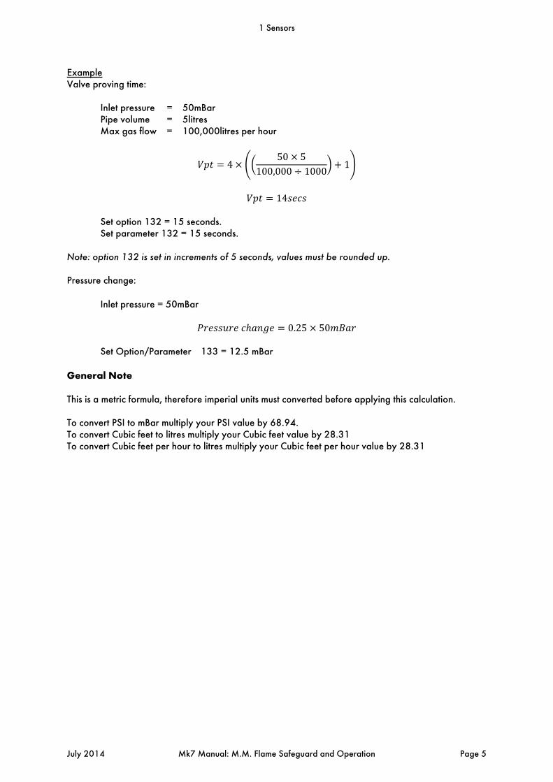
Example Valve proving time:
Inlet pressure = 50mBar Pipe volume = 5litres Max gas flow = 100,000litres per hour
450 5
100,000 10001
14
Set option 132 = 15 seconds.
Set parameter 132 = 15 seconds. Note: option 132 is set in increments of 5 seconds, values must be rounded up. Pressure change:
Inlet pressure = 50mBar
0.25 50 Set Option/Parameter 133 = 12.5 mBar
General Note This is a metric formula, therefore imperial units must converted before applying this calculation. To convert PSI to mBar multiply your PSI value by 68.94. To convert Cubic feet to litres multiply your Cubic feet value by 28.31 To convert Cubic feet per hour to litres multiply your Cubic feet per hour value by 28.31
1 Sensors
July 2014 Mk7 Manual: M.M. Flame Safeguard and Operation Page 5

1.2 Air Pressure Proving
Figure 1.2.i Air Pressure Proving
Figure 1.2.i shows the combustion air pressure monitoring philosophy of the Mk7 M.M. system PRESSURE SENSORS ARE DUAL CHANNEL & SELF CHECK NOTE: 1: ‘POS 2’ MUST BE 0.25” Wg (0.62mbar) HIGHER THAN ‘POS 1’ 2: MINIMUM PRESSURE IN NORMAL RUN MODE MUST BE HIGHER THAN ‘POS 2’ 3: ‘POS 8’ MUST BE SET EQUAL TO ‘POS 2’ OR HIGHER 4: DEFAULT SETTINGS FOR MINIMUM & MAXIMUM IS 15% ABOVE & BELOW ENTERED VALUE
1 Sensors
Page 6 Mk7 Manual: M.M. Flame Safeguard and Operation July 2014

1.2.1 Air Pressure Sensor
Quick connection flying lead (4 core) – 1.5m
Circuit board
Pressure switching unit
Sealing O-ring
¼” tapered male nipple NOTE: I.P. RATING 52 NEMA 5 MATERIAL SPECIFICATION ALUMINIUM POWER CONSUMPTION 0.1W MOUNTING VERTICAL AS SHOWN WORKING RANGE 0.3 TO 25 “ WG / -0.75 TO 65 MBAR/ 0 – 1 PSI (MM70005) 0.6 TO 50 “ WG / -1.5 TO 130 MBAR/ 0 – 2 PSI (MM70013) ZERO RANGE -1 TO 0.5 “ WG / -2.5 TO 1.25 MBAR (MM70005) -2 TO 1” WG / -5 TO 2.5 MBAR (MM70013)
1 Sensors
July 2014 Mk7 Manual: M.M. Flame Safeguard and Operation Page 7

1.2.2 Air Pressure Tapped Fitting
The Autoflame Mk7 Air Pressure Sensor is supplied with a negative pressure port. This can be removed and installed as shown below, to measure a differential pressure. This is only necessary where the air pressure at low fire is below 0.4" w.g. or 1 mbar or when it is a local code requirement.
See Options 145 to 149 in Mk7 Manual: M.M. Installation and Commissioning Guide.
1 Sensors
Page 8 Mk7 Manual: M.M. Flame Safeguard and Operation July 2014

1.3 Load Detectors
1.3.1 Steam Pressure Sensor
Electrical Connections Sensor Type
Plug sensor Lead Sensor Terminals Green (2) Green 38 Blue (3) Yellow 37 Red (1) Brown 39
N/A White Unused Not connected Screen S
For correct operation the detector must be installed with a pressure siphon loop. Do not install an isolation valve between the detector and the pressure vessel.
Plug fits correctly in one position only, do not force. Do not use case to tighten pressure connection. Maximum 2.5mm flat blade screwdriver for electrical connections IP Rating 65 NEMA 4 Torque Setting 15-20Nm O-ring material Viton Max storage temp -25°C to +85 °C Max operating temp -25°C to +85 °C Media temp (steam) -25°C to +85 °C Part No Actual Range Over Pressure Burst Pressure MM10010 1.5 - 55.0 PSI (0-3.80bar) 116 PSI (8bar 174 PSI (12bar) MM10008 30 - 330 PSI (0-23.0bar) 725 PSI (50bar) 1087 PSI (75bar) MM10009 50 - 550 PSI (0-38.0bar) 1160 PSI (80bar) 1450 PSI (100bar)
PG 7 Cable Entry 27mm (1 1/16”) across flats 1/4” NPTT
68
.00
mm
41.75mm
1 Sensors
July 2014 Mk7 Manual: M.M. Flame Safeguard and Operation Page 9

1.3.2 Water Temperature Sensor
Electrical Connections Wire Terminal Red 38 Blue 37
Range: 0 – 400°C, 0 - 752°F.
Cable Entry 2 core Screen
½” BSP Thread Connection
Stainless Steel Immersion Pocket
Wire Connections
82
mm
18
mm
Sta
nda
rd I
mm
ersi
on
dep
th 1
00
mm
1 Sensors
Page 10 Mk7 Manual: M.M. Flame Safeguard and Operation July 2014

1.3.3 Outside Temperature Compensation
Figure 1.3.3.i Outside Temperature Compensation Screen
OTC enables the boiler setpoint to be varied according to the outside air temperature, i.e. as the air temperature increases/decreases the boiler setpoint can be altered accordingly. The display shows the current outside temperature, night setback status, minimum setpoint and boiler setpoint. On the Mk7 M.M. the outside temperature compensation graph is displayed such that the outside temperature scale is from left to right as the outside temperature increases. The limits of operation of this feature can be set through the Options menu. To enable Outside Temperature Compensation, set Option 80 to 1.
Maximum boiler required setpoint at minimum outside temperature (Option 81). Minimum outside temperature (Option 82). Minimum boiler required setpoint at maximum outside temperature (Option 83). Maximum outside temperature (Option 84). Night Setback is activated by an input on Terminal 93 and reduces the required setpoint by a
value (Option 85). Minimum setpoint (Option 79). This sets the minimum required setpoint independent from
Option 83 and without changing the range that is set for the OTC. Adjust errors in the OTC sensor reading (parameter 88)
Note: If the actual outside temperature exceeds the boundaries set in Options 82 and 84, the boiler setpoint will remain at the maximum or minimum setpoints specified by Options 81 and 83 or 79.
1 Sensors
July 2014 Mk7 Manual: M.M. Flame Safeguard and Operation Page 11

Outside Temperature Sensor
I.P. RATING 65 NEMA 4 HOUSING ALUMINIUM POWER CONSUMPTION POWERED BY MK7 MM MOUNTING ANY ORIENTATION
Connections Sensor Terminal
Red 19 Blue 20
Fixing Holes
2 Core Screen Cable (2m length)
Plastic Water Tight Conduit (1m length)
Conduit Gland
Aluminium Body (101mm length)
1 Sensors
Page 12 Mk7 Manual: M.M. Flame Safeguard and Operation July 2014

2 FLAME SAFEGUARD
2.1 Burner Control Sequence Diagram
Diagram Notes If VPS is not optioned on the fuel selected, the VPS phases are bypassed. Point idle:
This phase is set at power up when no fuel selected on exit from lockout. Point recycle:
This phase is set on exit from firing and post purge if VPS has not operated after burner run.
Point post purge: This phase is set only if post purge is optioned.
Point standby:
This phase is set if VPS has operated after burner run. Normal lockout is reset when either the mains lockout reset input is set for 2 seconds or the display screen lockout reset button is pressed for 2 seconds. Prolonged lockout reset/special lockout is set if either the mains lockout reset input or display screen lockout reset input is set for 10 or more seconds. Normal lockout is set on exit from permanent lockout reset/special lockout after 20 seconds and is reset in the normal way. Blue waveforms indicate required condition. Values above/below waveform are time in seconds that the state must be continuously incorrect after which a lockout is set. If the waveform is not bold then the status is not important. The following burner control sequence diagrams are shown with example timings: 3 second window for UV detection for simulated flame 1 second window for UV loss for flame failure 3 second window for CPI loss for CPI input wrong state/ no CPI reset 3 second window for air switch loss for no air proving
2 Flame Safeguard
July 2014 Mk7 Manual: M.M. Flame Safeguard and Operation Page 13

2.1.1 Interrupted Pilot Gas
2 Flame Safeguard
Page 14 Mk7 Manual: M.M. Flame Safeguard and Operation July 2014

2.1.2 Interrupted Oil
2 Flame Safeguard
July 2014 Mk7 Manual: M.M. Flame Safeguard and Operation Page 15

2.1.3 Intermittent Pilot
2 Flame Safeguard
Page 16 Mk7 Manual: M.M. Flame Safeguard and Operation July 2014
2.2 Flame Scanner Types
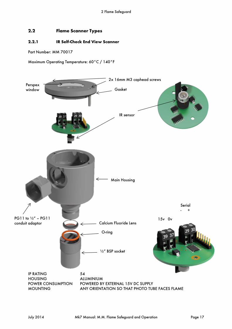
2.2.1 IR Self-Check End View Scanner
Part Number: MM 70017 Maximum Operating Temperature: 60°C / 140°F IP RATING 54 HOUSING ALUMINIUM POWER CONSUMPTION POWERED BY EXTERNAL 15V DC SUPPLY MOUNTING ANY ORIENTATION SO THAT PHOTO TUBE FACES FLAME
Serial - +
15v 0v PG11 to ½” – PG11 conduit adaptor
2x 16mm M3 caphead screwsPerspex window Gasket
IR sensor
Main Housing
Calcium Fluoride Lens
O-ring
½” BSP socket
2 Flame Safeguard
July 2014 Mk7 Manual: M.M. Flame Safeguard and Operation Page 17

2.2.2 Self-Check UV Scanner
Part Numbers: MM 60003/HS Maximum Operating Temperature: 50°C / 122°F NOTE: I.P. RATING 54 N.E.M.A. 5 POWER CONSUMPTION MAX 0.5W HOUSING ALUMINIUM MOUNTING ANY ORIENTATION
Connections Red Terminal 51 Blue Terminal 50 Screen Terminal S Yellow Terminal 21 Green Terminal 22
O-ring
Quartz glass
PG11 to ½” conduit adaptor
Main housing
Stepper motor housing
Red LED shows UV Detection
15
0m
m A
ssem
ble
d L
eng
th
Ø65mm
Gasket
2x 16mm M3 caphead screws
Perspex window
Paddle
Stepper motor housing
UV cell
Yellow LED shows shutter operation
1” BSP socket (1” NPT for /U only
2 Flame Safeguard
Page 18 Mk7 Manual: M.M. Flame Safeguard and Operation July 2014

2.2.3 Self-Check Side View UV Scanner
Part number: MM60003/HS/SV Maximum operating temperature: 50°C / 122°F NOTE: I.P. RATING 54 POWER CONSUMPTION MAX. 0.5W HOUSING & LID ALUMINIUM UV CELL HIGH INTENSITY
Connections Red Terminal 51 Blue Terminal 50 Screen Terminal S Yellow Terminal 21 Green Terminal 22
23
0m
m A
ssem
ble
d L
eng
th
11
1m
m A
ssem
ble
d L
eng
th
Mirror
Quartz glass
UV viewing opening
Viewing tube
PG11 to ½” conduit adaptor
Main housing
Gasket
Perspex window2x16mm M3 caphead screws
2 Flame Safeguard
July 2014 Mk7 Manual: M.M. Flame Safeguard and Operation Page 19
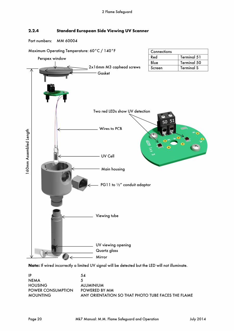
2.2.4 Standard European Side Viewing UV Scanner Part numbers: MM 60004 Maximum Operating Temperature: 60°C / 140°F Note: If wired incorrectly a limited UV signal will be detected but the LED will not illuminate. IP 54 NEMA 5 HOUSING ALUMINIUM POWER CONSUMPTION POWERED BY MM MOUNTING ANY ORIENTATION SO THAT PHOTO TUBE FACES THE FLAME
Connections
Red Terminal 51
Blue Terminal 50 Screen Terminal S
16
0m
m A
ssem
ble
d L
eng
th
Mirror
Quartz glass
UV viewing opening
Viewing tube
PG11 to ½” conduit adaptor
Main housing
UV Cell
Wires to PCB
Two red LEDs show UV detection
Perspex window
Gasket
2x16mm M3 caphead screws
2 Flame Safeguard
Page 20 Mk7 Manual: M.M. Flame Safeguard and Operation July 2014

2.2.5 Standard North American UV Scanner – End Viewing Part numbers: MM60004/U MM60004/HSU Maximum operating temperature: 60°C / 140°F
Connections Red Terminal 51 Blue Terminal 50 Screen Terminal S
Perspex window
2x16mm M3 caphead screws
Gasket
Standard UV Cell
Main housing
Two red LEDs showing UV detection
PG11 to ½” conduit adaptor
Quartz glass
O-ring
½” NPT thread socket
2 Flame Safeguard
July 2014 Mk7 Manual: M.M. Flame Safeguard and Operation Page 21

NOTE:
I.P. RATING 54 NEMA 5 HOUSING ALUMINIUM POWER CONSUMPTION POWERED BY MK.7 MM MOUNTING ANY ORIENTATION SO THAT PHOTO TUBE FACES FLAME
57.00mm
10
8.0
0m
m A
ssem
ble
d L
eng
th
½” NPT thread socket
O-ring
Quartz glass
PG11 to ½” conduit adaptor
Main housing
High Sensitivity Cell
High Sensitivity CellTwo red LEDs show UV detection
Gasket
2x16mm M3 caphead screws
Perspex window
2 Flame Safeguard
Page 22 Mk7 Manual: M.M. Flame Safeguard and Operation July 2014

2.2.5 Swivel Mount Assembly
Figure 2.2.5.i Swivel Mount Assembly, 1” Connection
2.3 Selection Of UV Scanner Types 2.3.1 Normal Sensitivity If the distance from the UV scanner to the flame is 500mm (20 inches), the normal sensitivity UV scanner types may be used. Normal Sensitivity Scanner Types MM 60004 Standard Side View MM 60004/U Standard End View The following considerations must kept in mind when selecting a UV scanner,
- Flame size - Flame shape (dependent on the burner used) - Flame intensity (a function of flame size and shape and fuel used) - Flame obstructions
When the signal strength is low, a high sensitivity scanner type might be necessary for distances below 500mm (20 inches). Note: All self-check UV scanners are high sensitivity as standard.
2 Flame Safeguard
July 2014 Mk7 Manual: M.M. Flame Safeguard and Operation Page 23

2.3.2 High Sensitivity If the distance from the UV scanner to the flame exceeds 500mm (20 inches) a high sensitivity UV scanner type is recommended. High Sensitivity Scanner Types MM 60003/HS Self Check End View MM 60003/HS/SV Self Check Side View MM 60004/HSU Standard End View The maximum safe distance a UV scanner can be from a flame is dependent on
- The intensity of UV radiation emitted from the main flame and pilot flame - The geometry of the combustion chamber and available space
This will vary between applications but the maximum distance allowed is 1500mm (6 ft) between a high sensitivity scanner and flame. Note: The above information is based on the results of tests conducted using a laboratory pilot flame supplied from a Bunsen burner of flame size 100x20mm. 2.3.3 UV Installation
The end view scanner is show in Figure 2.3.3.i. The size of the flame is allowed for the distance the UV scanner is away from the flame.
Figure 2.3.3.i UV Scanner Installation
2 Flame Safeguard
Page 24 Mk7 Manual: M.M. Flame Safeguard and Operation July 2014

2.3.4 UV Self Adaptive Pulse Width Modulation
Figure 2.3.4.i UV Timing Diagram
Figure 2.3.4.i shows a timing diagram for the UV signal. NOTE 1: After first safety time, voltage is reduced by 5 volts every 500ms. This is providing the flame signal is above the U.V. setpoint. If below the U.V. threshold, voltage will remain at 330 volts. The voltage will not increase during main flame operation. NOTE 2: If 5 counts or less have been detected over any 730ms period, the system will invoke a lockout. A short circuit between the two wires connected to the U.V. would produce 3 counts or less. This is the reason for nominating 5 counts as the lockout level. NOTE 3: During normal operation, 300 volts would be applied for a 240ms period after the second safety time. This is providing the U.V. signal is above the U.V. setpoint which is set at 25 counts. The setpoint cannot be adjusted. NOTE 4: If the UV count is above 25 counts then the time voltage is applied to the UV sensor is decreased by 1 ms every 500 ms. This time is reduced until a maximum of 10ms has been reached. This helps preserve the life of the UV scanner as the time that voltage is applied to the scanner is reduced dramatically. NOTE 5: Every 500ms the recorded counts are averaged and displayed on the M.M. screen. Note: When using a self-check scanner the timing reduction resets the minute when the paddle operates.
2 Flame Safeguard
July 2014 Mk7 Manual: M.M. Flame Safeguard and Operation Page 25

2.3.5 Dual UV and IR Scanner Operation (AGA) Please contact Autoflame before use. Dual scanner operation works by using a self-check IR scanner and a self-check UV scanner to detect the flame simultaneously. Each scanner works independently so that if one scanner fails to see a flame when there should be a flame but the other scanner still sees a flame the Mk7 will lockout on no flame signal. The same goes for a simulated flame lockout only one scanner has to see a flame when there should not be a flame for the Mk7 to lockout. Dual scanner operation is designed to give extra safety to the flame detection system by there being a second scanner to verify that the other scanner is working correctly and is detecting a flame correctly in addition to the self-diagnostics built into the Mk 7. Both scanners work independently in detecting a flame signal so it is not required that the two scanners have to read the same flame signal strength. It is recommended that that a good flame signal is found on both scanners to ensure reliable operation of the dual scanners. To enable dual scanner operation Option/Parameter 122 should be set to 3. Also ensure that Option/Parameter 111 is set to 1 for self-check operation of the scanners. There are no special wiring requirements needed the IR and UV scanners should be connected to the Mk7 M.M. as normal. The AGA (Australian Gas Association) standard requires that there are 2 types of technologies checking the flame i.e. the self-check UV scanner and the self-check IR scanner. Please contact Autoflame for more information.
2 Flame Safeguard
Page 26 Mk7 Manual: M.M. Flame Safeguard and Operation July 2014

2.4 Flame Detection Using An External Flame Switch To configure operation with a flame switch Option/Parameter 122 must be set to 1. The operation of Terminals 85 and 86 must be as follows: When the flame switch indicates no flame, the voltage on Terminal 85 must be 0Vac, and the voltage on Terminal 86 must be mains voltage (110/230Vac). When the flame switch is indicating the presence of a flame, the voltage on Terminal 85 must be mains voltage (110/230Vac), and the voltage on Terminal 86 must be 0Vac. Terminal 85 is the functional input for detecting the flame. Terminal 86 is solely for the purpose of checking that Terminal 85 is operating correctly. Terminal 86 must be seen to be the inverse of Terminal 85, i.e. if Terminal 85 is at 0Vac, terminal 86 must be at mains voltage and if Terminal 85 is at mains voltage, Terminal 86 must be at 0Vac. If Terminal 86 does not follow the inverse of Terminal 85 the following lockout will occur – ‘Terminal 86 inverse.’ Note: High purge interlock (parameter #92) will not operate with flame switch. 2.4.1 Flame Switch Configuration Within the M.M. there is a latency of 250 milliseconds on the monitoring of Terminal 85. To ensure a 1 second overall flame failure response time, it is essential that the response time of the flame switch is set to no more than 750 milliseconds. Flame switches often provide a volt free changeover contact to indicate the flame status. Alternatively, they may provide a pair of `inverse’ outputs. If the flame switch only provides a single output terminal, a relay will have to be installed between the flame switch and the M.M. to provide a set of volt free changeover contacts.
2 Flame Safeguard
July 2014 Mk7 Manual: M.M. Flame Safeguard and Operation Page 27

3 HAND, LOW FLAME HOLD AND AUTO
3.1 Hand Operation
‘Hand’ operation enables the fuel valve and air damper (and other channels) positions to be set to a specific position, in the range of minimum to maximum flame. As a default setting (Option 60) the next time the system is put into a hand operation, the system will take on a fuel/air ratio in the commissioning curve similar to the current firing rate. The M.M. system sets the channel positions to the hand position whenever there is a mains signal on Terminal 94. Once the burner is firing the ‘hand’ position can be adjusted by switching to the Status Screen and using the ‘Increase’ and ‘Decrease’ buttons on the Flame screen, under where the current firing rate is displayed. When switching from Hand to Auto the M.M. will stay in the same servo positions and will not immediately increase or decrease its firing rate depending upon the actual and required temperature/pressure modulation resumes after a small time delay. It is also possible to store a hand position, where by once HAND is selected, the unit will modulate to a stored firing rate (see option 60 and set to last hand position). If Hand and Low Flame Hold are selected at the same time via Terminals 94 and 95, then Low Flame Hold takes priority. Note: Lead/Lag and sequencing will not operate if either Terminal 94 or 95 has a mains voltage. 3.2 Low Flame Hold
‘Low Flame Hold’ and ‘Hand’ operation are only effective when the burner is firing. They have no effect when the burner is off or during the burner start up cycle. They are affected by applying a mains voltage signal to Terminal 95 for low flame hold, or Terminal 94 for hand operation. When these inputs have no mains signals applied, the system is in an automatic mode and modulates according to the PID control. Low flame hold is brought into operation if Terminal 95 has mains voltage applied when the burner is modulating or firing. The minimum flame position will be maintained from now on, until the input from Terminal 95 is removed. Low flame hold will be established again by applying an input to Terminal 95 again. During low flame hold the PID control is ignored. When switching from Low Flame Hold to Auto the M.M. will increase/decrease its firing rate to the last known Auto firing rate. 3.3 Auto Operation The M.M. ‘Auto’ operation enables the burner modulation to maintain the setpoint, the firing rate will modulate according to how far away the actual temperature or pressure is away from the required setpoint. The firing rate is determined from the fuel flow metering entered via option 57; the more accurate the fuel flow metering, the more accurate the firing rate. The Intelligent Boiler Sequencing features turns the burners on and off as required according to the firing rate of the boilers in that sequence loop.
3 Hand, Low Flame Hold and Auto
Page 28 Mk7 Manual: M.M. Flame Safeguard and Operation July 2014

4 PID CONTROL
4.1 Introduction
The standard control algorithm used by Autoflame to control the fuel/air ratio is a PID controller; Proportional-Integral-Derivative controller. The control algorithm compares the actual measured temperature or pressure and compares it to the user specified setpoint temperature or pressure. Depending on the measured and setpoint values, the controller will then either modulate the burner up (increase) or down (decrease). The rate of change or speed of the burner modulation in relation to changes in measured temperature or pressure is dependent on the settings of the PID controller as stated in the Options and Parameters sections. The PID controller action is the sum of the “Proportional” + “Integral” + “Derivative” actions of the PID controller. Each contributes to how the controller modulates the burner and each operates as outlined below.
4.2 Proportional Band
The Proportional term is specified in Option 6 by defining the “Proportional band” (P-Band). The P-Band is simply an offset from the setpoint pressure or temperature. Outside and below the P-Band, the controller will modulate the burner at maximum flame, upon reaching the P-Band, the controller will modulate the burner linearly down (see Option 6).
Figure 4.2.i Proportional Band
4 PID Control
July 2014 Mk7 Manual: M.M. Flame Safeguard and Operation Page 29

4.3 Integral Control
The Integral term is specified in Option 7, where the “Integral time”, also known as “Reset time”, is set. Within a threshold of the Proportional Band, the integral term has the effect of increasing or decreasing the burner firing rate by a specific amount every “n” seconds. The amount the firing rate is adjusted by is specified in Parameter 106, default is 10% of the difference between the measured and setpoint temperature or pressure values, and the time period this amount is added, every “n” seconds, “n” is specified in Option 7, default is 60s.
Figure 4.3.i Integral Control
(Parameter 48 = 0.8, Integral operation band of p-band)
4 PID Control
Page 30 Mk7 Manual: M.M. Flame Safeguard and Operation July 2014

4.4 Derivative Control
The Derivative term of the control system analyses the rate of change in the difference between the measured and set point temperature or pressure. Derivative specific options are set in Option 37, 38 and 39. The time interval over which the compared and measured temperature or pressure values are taken is set in Option 37, the derivative dead-band or margin above and below the required set point in which no derivative action occurs is set in Option 38, and the response sensitivity as a percentage of firing rate increase or decrease is defined in Option 39.
Figure 4.4.i Derivative Control
NOTE: The derivative action occurs at all points outside of the deadband. This includes within the proportional band.
4 PID Control
July 2014 Mk7 Manual: M.M. Flame Safeguard and Operation Page 31

4.5 PID Controller Considerations
The majority of applications can be controlled adequately using just the Proportional and Integral settings; a PI control setup. By default, the Derivative term is set to zero. This is due, in part, to the aggressive nature this term can have on the control action which makes it suited to a small number of combustion processes. Modification to the settings governing the Autoflame control system should only ever be carried out by qualified combustion engineers. Changes to the Autoflame control system setup has the potential to make the controller operate in an unstable and potentially unsafe manner. 4.5.1 Super “I”
The advantage of the standard PID was that it was very easy to set up and that in 99% of applications it worked incredibly well. Recently one or two applications have presented themselves where the above control form does not carry enough “I” to achieve a response that enables the control to lock on to the required value. The applications that have required additional “I” control have been water tube boilers where there is a high proportion of heat transfer surface to water volume which results in a low thermal inertia and therefore the need for a more dynamic control response. A radical solution to this is the control form we have labelled “Super I” to differentiate this from the existing P+I control. The “Super I” has the following adjusters and set up features. 1) Deadband – this is accessed via Parameter 105. The range is 0 - 10 and this can be adjusted
in increments of 1. The range of 10 would apply to 10°F, 10°C, 10 psi or 1.0 bar. 2) “I” Offset – this sets the point at which the “Super I” control algorithm is put into operation.
The adjustment of this “I” control setting can be accessed via Parameter 102. The range is 1 to 50. The default value is zero which turns off the “Super I”. The range can be up to 50°C, 50°F, 50 psi or 5.0 bar. The incremental adjustment of this “I” value is 1 (i.e. 1°C, 1°F, 1 psi or 0.1 bar).
3) Speed of integration – the range available in 0-30 seconds. There is no default value. The
adjustment of this “I” control setting can be accessed via Parameter 103. The adjustment of the speed of integration is in 1 second increments.
4) Amount of integration as a degree angular increment – the range of this adjustment is 0 to 5
degrees angular rotation. The range increases in increments of 0.1 degrees angle. The adjustment of this “I” control setting can be accessed via Parameter 104.
NOTE : Please note that the standard PI algorithm turns off its own “I” component when it meets the
“Super I” band. Please see the graphical example which sets out to show the interaction between the original P+I control and the additional “Super I” algorithm.
4 PID Control
Page 32 Mk7 Manual: M.M. Flame Safeguard and Operation July 2014

Figure 4.5.1.i Super “I” Control
4 PID Control
July 2014 Mk7 Manual: M.M. Flame Safeguard and Operation Page 33

5 INTELLIGENT BOILER SEQUENCING
5.1 Overview of Sequencing
5.1.1 Features and Benefits
The Intelligent Boiler Sequencing feature (IBS), which is included in every M.M. module, further extends the application possibilities of the system. The objective of this control form is to ensure that the minimum number of boiler/burner units is in operation at any one time to satisfy the heat or steam requirement imposed upon the boiler plant in the case of multi-boiler installations. 5.1.2 Hot Water Boilers Sequencing
A maximum of ten M.M. and E.G.A. modules may be interconnected by a two wire screened data cable. Any M.M. interconnected may be selected as the lead boiler for the sequencing. This identifying of ‘lead’ boiler is achieved in two ways:
1. Connecting a mains voltage onto Terminal 88. 2. Instructing the modules via the D.T.I. module (Data Transfer Interface) by software.
Once a lead boiler has been selected the system works in the following way: Every scan time (set in Option 35) the sequencing software in the lead boiler identifies its own firing rate by looking at the fuel flow metering data the unit has. Having established percentage firing rate, and maximum heating capacity, the IBS software calculates the amount of heat being contributed to the system by the boiler. The IBS software in the lead M.M. module then contacts in turn each of the modules connected to this loop and gathers similar information from each. The lead M.M.’s IBS software then calculates the minimum number of boiler/burner units that need to be operational to satisfy the building load, imposed upon the plant at that time and switches the remainder off. Terminal 78 on the M.M. is a switched neutral connection for controlling a two port valve that would normally be installed in the boilers return pipe connection to the common return header. This facility ensures that boilers that are switched ‘offline’ do not contribute return temperature water to the flow header thereby diluting the flow temperature to the building. 5.1.3 Steam Boilers Sequencing
When the IBS software control package is applied to steam boilers, its operation is exactly the same as above but with additional features and enhancements as explained below. In the case of heating boilers only two states in the control form exist, either on or off. When steam boiler variations of IBS are optioned there are three states which are controlled sequentially. The first is ‘online’, this is when the boiler is operating purely under the control of the M.M. modules internal PID control. The second state is ‘standby warming’. In this case the boiler is operated at a reduced pressure setpoint and runs for a number of minutes each hour. E.g. if the online boiler or boilers are set at a setpoint of 7 Bar (100 PSI) the standby warming boiler can be set to reach a ‘phantom’ setpoint of 5 Bar (72 PSI). In this way if the load increases the standby warming boiler can begin to contribute steam quickly. The reduced setpoint is a user variable option in the same way as the normal control
5 Intelligent Boiler Sequencing
Page 34 Mk7 Manual: M.M. Flame Safeguard and Operation July 2014
pressure setpoint. The number of minutes run time is also adjustable. The reduced pressure setpoint for the 5 Bar (72 PSI) warming phase is known as the phantom setpoint. The third state is ‘Offline’, this is with the burner shut down and the boiler cold. If the load on the boiler house increases, this boiler would move into a ‘warming’ condition. Apart from the variations detailed above, the steam sequencing works in precisely the same way as the heating boiler sequencing: the sequencing software package ensures that at all times the minimum number of boilers are operational to satisfy the load imposed on the boiler house. Note: It should be appreciated that all data and control variables can be shown on a computer via the addition of a D.T.I. module to the data loop. The computer can be sited locally in the boiler house or the whole system can be addressed remotely. The Mk7 D.T.I. emulates the screens of the Mk7 M.M. and E.G.A.s including the Intelligent Boiler Sequencing screen showing firing rates and burner status. During firing, a Mk7 M.M. or a Mini Mk7 M.M. will be removed from the sequence loop should any of the following occur:
Communications to the M.M. has timed out The M.M. has been disabled remotely via the D.T.I. or a BMS with option 16 set to 3 Option 16 on the M.M. is not set to 1 or 3 The M.M. is in an error, burner lockout or expansion alarm state The M.M. has not started modulating within the required time (parameter 5) The D.T.I. is manually controlling the firing rate Modulation exerciser is being used Option 47 has be set for cold-start routine The M.M. is in Hand or Low Flame Hold mode
5 Intelligent Boiler Sequencing
July 2014 Mk7 Manual: M.M. Flame Safeguard and Operation Page 35

5.2 Sequencing Options and Parameters Note: The Options and Parameters must only be changed by factory trained and certified technicians who have a thorough appreciation of the Autoflame combustion systems and the combustion process in general. Any person changing the Options and Parameters who does not have the correct factory training and understanding of these settings/adjustments may place themselves and others in a potentially dangerous situation.
5 Intelligent Boiler Sequencing
Page 36 Mk7 Manual: M.M. Flame Safeguard and Operation July 2014

Option N
o.
Facto
ry Setti
ng
Option V
alue
Descriptio
n
3 0 DTI Comms Mode0 Mk6 DTI - 9600bps
1 Mk7 DTI - 19200bps
16 0 Lead/Lag (IBS) and DTI: A lead boiler can be selected by connecting a line voltage to terminal 88 on
the appropriate M.M. Only 1 M.M. may be selected as lead boiler at a time, or the sequencing will
not operate. The lead boiler can be selected via the D.T.I. However, for this to be effective all the M.M.
units on the system must have Terminal 88 volt free. Line voltage on Terminal 88 overrides the D.T.I.
command.
0 No sequencing - M.M. units still communicate and can be seen on the D.T.I.
1 Sequencing enabled - M.M. units will respond to sequencing commands. Lead boiler is selected by a line
voltage on terminal 88.
2 Setpoint & enable/disable commands accepted from D.T.I.
3 Both 1 and 2.
Note: Accurate fuel flow metering must be entered for sequencing to operate. An RS485 data cable
(Belden 9501) must be connected between each M.M. unit (see section 3.4.6 for correct connection).
33 1 M.M. Identification: The identification number must be set on all M.M. Units in the boiler house. If
not, then problems will occur with sequencing/twin burner and with the D.T.I. communications. Each
unit must have a different identification number.
1 -10 Identification number
34 5 Rating of Burner:1 - 999 See Option 77 for units.
35 10 Sequence Scan Time: This is the time period between sequencing requests from the lead M.M. On
the sequence scan time, the lead M.M. will demand lag burners to be brought online or offline,
depending on load requirements. See Parameters 86 and 87 for thresholds.
1 - 100 Sequence scan time (minutes).
Note: Accurate fuel flow metering must be entered for sequencing to operate. An RS485 data cable
(Belden 9501) must be connected between each M.M. unit (see section 1.4 for correct connection).
40 0 Warming Facility for Low Pressure Steam Sequencing: For lead/lag (sequencing)
applications where check (non-return) valves are not installed, it is not possible to use a phantom setpoint
to keep the boilers in a standby warming condition. Therefore, the facility exists to install a thermostat
(aquastat) in the boiler shell. The thermostat will input 230V/120V on Terminal 93 and this initiates
warming (see option 41). The boiler will remain in a warming state based on the settings for Options
53 and 54.
0 Disabled
1 Enabled
41 0 2/3 State Sequencing: This option sets 2 states of operation for the lag boilers. Either one boiler is
kept in a standby warming state and the other boilers are off, or all lag boilers are kept in a standby
warming state and there are no off boilers.
0 3 State Sequencing: LEAD, STANDBY, OFF, OFF, OFF, OFF...
1 2 State Sequencing: LEAD, STANDBY, STANDBY, STANDBY...
42 20 Warming facility for medium/high pressure steam sequencing - phantom setpoint:For lead/lag (sequencing) applications where check (non-return) valves are installed, it is possible to
use a phantom setpoint to keep the boilers in a standby warming condition. This value is an offset below
the normal required setpoint. When the phantom setpoint is in effect, the burner is held at a low flame
position.
0 - 100 If Centigrade, Fahrenheit or PSI units effective.
0 - 10.0 If Bar units effective.
5 Intelligent Boiler Sequencing
July 2014 Mk7 Manual: M.M. Flame Safeguard and Operation Page 37

Option N
o.
Facto
ry Setti
ng
Option V
alue
Descriptio
n
43 5 Offset above phantom setpoint when the burner stops:
2 - 50 If Centigrade, Fahrenheit or PSI units effective.
0.2 - 5.0 If Bar units effective.
44 5 Offset below phantom setpoint when the burner starts up:
2 - 50 If Centigrade, Fahrenheit or PSI units effective.
0.2 - 5.0 If Bar units effective.
53 0 Steam Boiler Sequencing Burner 'off' time: The steam boiler type sequencing is enabled by
setting option 1 to a respective pressure sensor. Options 42, 43 and 44 are relevant to the "standby"
boiler operation.
0 Off
1 - 200 Burner "Off" time (minutes) during warm up cycle.
Intelligent Boiler Sequencing - Steam boiler applications.
54 5 Steam Boiler Sequencing Burner 'on' time:
1 - 30 Burner "On" time (minutes) during warm up cycle.
Intelligent Boiler Sequencing - Steam boiler applications.
57 0 Fuel Flow Metering: Fuel flow metering is required for several functions to work correctly. Autoflame
recommend entering dummy points if a fuel meter is not available to measure actual flow. Setting this to
1 will initiate fuel flow metering once the burner is firing.
0 No flow metering.
1 Flow metering operates and recalibrated.
2 Totalised flow metering reset to zero for selected fuel.
77 0 Burner rating units: Display purposes only for fuel flow metering.
0 KW x 100 /hr
1 Kg x 100 /hr
2 MW /hr
3 Btu x 100 /hr
4 Hp x 100 /hr
5 lbs x 100 /hr
6 Btu x 1000 /hr
7 Hp x 10 /hr
8 lbs x 1000 /hr
9 Btu x 1000 000 /hr
5 Intelligent Boiler Sequencing
Page 38 Mk7 Manual: M.M. Flame Safeguard and Operation July 2014

Parameter N
o.
Facto
ry Settin
g
Parameter V
alue
Descriptio
n
1 3 0 - 20 Sequencing: Offset value when unit goes offline. If the standby boiler fails to start the scan time will be
decreased by the value set (minutes). i.e. Scan time is 10 minutes and value is 3 then the next scan
time will be reduced to 7 minutes when the standby boiler fails to start.
2 1 1 - 10 Sequencing: Time between data requests (seconds). Bus driver requests information every 'n' seconds,
MM's transmits every 'n' seconds, the DTI only listens to transmissions.
3 1 1 - 10 Sequencing: Number of boilers initally set on after powerdown.
5 4 1 - 50 Sequencing: Modulation time out (minutes). i.e. If the boiler is not modulating after being asked to
contribute to the load after this time it is kicked out of the sequence loop.
E.g. Burner must start to modulate in 4 minutes from being asked to contribute to the load.
48 0.8 Integral control threshold (I): This is a percentage below the required setpoint to the proportional band
offset at which point the integral control takes effect. E.g. If the required setpoint is 100 PSI, option 6 is set to
10 PSI, and parameter 48 is set to 0.8, then the integral control will take effect when the actual value is above
92 PSI.
0 - 99 %
57 0 Sequencing: Highest M.M. ID. This parameters speeds up the communications during sequencing.
0 - 10
62 0 0 - 1 Hot water sequencing: If this Parameter is set to 1 then the hot water sequencing will operate in the same
way as the steam sequencing (contact Autoflame before use).
83 0 Display diagnostic values0 Disabled
1 Enabled
84 0 Display diagnostic values for Intelligent Boiler Sequencing0 Disabled
1 Enabled
86 0 Intelligent Boiler Sequencing change down threshold: If left at 0, change down threshold is 85%.
0 - 99 %
87 0 Intelligent Boiler Sequencing change up threshold: If left at 0, change up threshold is 95%.
0 - 100 %
101 0 Shuffle sequencing0 Disabled
1 Sequence order changed through D.T.I.
5 Intelligent Boiler Sequencing
July 2014 Mk7 Manual: M.M. Flame Safeguard and Operation Page 39

5.3 Guide to Commissioning Sequencing **Note: Recommended data cable to be used for sequencing wiring is Beldon 9501 in daisy chain configuration.** Before any attempt is made to implement sequencing operation it is necessary that the fuel/air positions and fuel flow metering are already entered. Refer to the Mk7 Manual: M.M. Installation and Commissioning Guide for comissioning fuel/air positions and implementing fuel flow metering. The following Options/Parameters are used for both hot water sequencing and steam sequencing. Option 3 – Set the communication speeds depending on whether you are using the current Mk7 D.T.I. or the old Mk6 D.T.I. Option 16 - 1 or 3 to enable sequencing. Option 33 – Sets the ID number of the M.M. No two M.M.’s can have the same ID number in the same sequencing loop otherwise the two M.M.’s will drop in and out of the sequencing loop. Option 34 –Sets the rating of the burner and is used to calculate how much heat/pressure the boiler is contributing to the system. The units are set in Option 77. Option 35 – Sets the scan time in minutes. This scan time has a critical effect on the responsiveness of the sequencing system as it is this time that dictates when the lead M.M. checks the system to turn burners on or off. Too long of a scan time and sudden demand can cause the header pressure to drop. Too short of a scan time and another boiler may be brought online before another boiler has started firing. The scan time normally should be set to at minimum, the start-up time for the burner. Option 57 – Sets the fuel flow metering, as Intelligent Boiler Sequencing is based on firing rate, it is important that the fuel flow metering is calibrated correctly. Parameter 57 – Set the value to the highest numbered M.M. in the sequence loop; this speeds up the communications between the M.M.’s if less than 10 M.M.’s are in the sequencing loop. Parameter 86 – Sets the change down threshold. This change down threshold is based on the total firing rate of the last two boilers firing rate. For example three boilers are sequenced ID 1 is at 100% and ID’s 2 and 3 are at 40%. Since the last two boilers in the sequencing loop have a combined firing rate of 80% which is below a set 85% threshold then ID 3 will be shutdown and the load maintained by burners 1 and 2. Parameter 87 – Sets the change up threshold. This is based solely on the firing rate of the last boiler to be brought online. Once the firing rate of this burner reaches the threshold the next burner in the sequencing loop will be brought online. For example once the firing rate reaches the set 95% in the lead boiler the first lag boiler will be brought online to contribute to the load. Parameter 101 – Sets shuffle sequencing for when implementing sequencing with the D.T.I. Parameter 1 – Sets the offset value of the scan time for when the unit goes offline. For example, if a standby burner fails to start when requested, the scan time will be decreased by the offset set, until it is automatically removed/ignored from the communication loop. Parameter 2 – Sets how often the ‘bus driver’ and M.M. request and transmit information. Parameter 3 – Sets the number of boilers which are initially set on after powerdown.
5 Intelligent Boiler Sequencing
Page 40 Mk7 Manual: M.M. Flame Safeguard and Operation July 2014

Parameter 5 – Sets the time delay for which a burner will get automatically removed/ignored from the sequencing loop, if it fails to modulate after being requested to contribute to the load. 5.3.1 Implementing Hot Water Sequencing The following Options/Parameters are used for hot water sequencing and some need to be set to certain values to implement hot water sequencing. Option 53 – MUST BE SET TO 0 for hot water sequencing. This disables standby warming which is only used in steam sequencing. Option 41 – MUST BE SET TO 0 for hot water sequencing. This sets the 2/3 state sequencing to 3 state sequencing. With hot water sequencing it is possible to use Terminal 78 which is a switched neutral to control the two port valve. This works by switching to neutral once the burner has stopped firing but if the temperature of the boiler ever gets above the required set point then Terminal 78 will switch back even if the boiler is not firing. 5.3.2 Implementing Steam Sequencing The following Options/Parameters are needed to setup steam sequencing. Option 41 – Sets 2/3 state sequencing. The first state is online where the boiler is firing. The second state is standby where the boiler will run through its standby warming sequence as set in Options 53 and 54. The third state is offline where the boiler is cold. Options 53 – Sets the standby warming off time. This is the time in minutes for how long the boiler will be off for during standby warming. Option 54 – Sets the standby warming on time. This is the time in minutes for how long the boiler will be in low flame hold for the boiler to heat up to its phantom setpoint. Options 42, 43 and 44 set the phantom setpoint. Option 42 – Sets the phantom setpoint to which the burner will aim to maintain when in the warming/standby phase. This is set as an offset of the ‘on’ status required setpoint. Option 43 – Sets the offset above the phantom setpoint when the burner will stop during warming. Option 44 – Sets the offset below the phantom setpoint when the burner starts up during warming. Option 40 – Sets the sequencing for low pressures steam applications via an input to terminal for the warming aqua stat.
5 Intelligent Boiler Sequencing
July 2014 Mk7 Manual: M.M. Flame Safeguard and Operation Page 41

5.4 Electrical Schematics
5.4.1 Sequencing Connection Diagram
5 Intelligent Boiler Sequencing
Page 42 Mk7 Manual: M.M. Flame Safeguard and Operation July 2014

5.4.2 DTI Sequencing Connection Diagram
5 Intelligent Boiler Sequencing
July 2014 Mk7 Manual: M.M. Flame Safeguard and Operation Page 43

5.5 IBS Examples 5.5.1 Hot Water Sequencing Example
5 Intelligent Boiler Sequencing
Page 44 Mk7 Manual: M.M. Flame Safeguard and Operation July 2014

5.5.2 Single/Twin Burner Example
5 Intelligent Boiler Sequencing
July 2014 Mk7 Manual: M.M. Flame Safeguard and Operation Page 45

5.5.3 Example Of IBS Communications
5 Intelligent Boiler Sequencing
Page 46 Mk7 Manual: M.M. Flame Safeguard and Operation July 2014

6 TWIN BURNER OPERATION
6.1 Twin Burner Commissioning
Options 14 and 33 have to be set to correctly implement twin burner operation. For commissioning purposes it is easiest to set Option 14 on each M.M. to value 0, and commission each burner individually. It is the commissioning engineer’s responsibility to ensure that no adverse effects are caused as a result of this, particularly, stress to a boiler not designed to have only one burner firing. If this is the case then both burners must be commissioned simultaneously. If using the twin burner the slave M.M. MUST HAVE identical software to the water level M.M. unit, i.e. the MM, BC, DI must be the same for both units. AFTER COMMISSIONING SET OPTION 14 TO IT'S TWIN BURNER VALUE ON BOTH M.M.s Before commencing commissioning set the following options (refer to options section for more details): Option 33: The ID number for the M.M.s must be set correctly. The master burner must have an odd numbered ID number and the slave burner must have the next consecutive even numbered ID. If the master M.M. is to 5, then the slave M.M. must be set to 6. Other options may be set as usual.
6.2 Normal Operation
Only the odd numbered M.M. needs an input on Terminal 88 to make this burner the lead burner. If a connection is made to the even number M.M. it will be ignored for sequencing. The same applies for the hand/auto/ low flame hold inputs on Terminals 94/95, i.e. they do not need any connection on the even number M.M. if Option 14 = 1. If Option 14 = 2 or 3 then Terminals 94/95 should be wired as normal for hand operation. The even number burner always takes its load index from the odd number burner including when in ‘Hand’ mode. If communications between the two burners fail, each M.M. will open its internal stat and displays on each M.M. show a yellow box on the flame screen to indicate a communications failure if Option 14 = 1. If Option 14 = 2 or 3 then the 2 M.M.s run stand- alone/ with water level. When entering the fuel flow metering for sequencing purposes it is necessary to put both M.M.s into the “Fuel Flow Metering” mode at the same time, i.e. Do not set the Fuel Flow Metering on one M.M. then the other as this could lead to thermal stress on the boiler as there will be a difference in firing rate between the two burners. Also to avoid thermal stresses the Fuel Flow Metering “points” must be entered at the same time on both M.M.’s so that both M.M.’s have the same firing. i.e. “point” 10 must be done on both MM’s before entering “point” 9. If Option 14 = 1, both burners fire simultaneously and together at all times, then the internal stat of both M.M.s will open if there is a period of more than 10 seconds when one M.M. is modulating and
6 Twin Burner Operation
July 2014 Mk7 Manual: M.M. Flame Safeguard and Operation Page 47
the other is not. Therefore, both burners will be off. If one burner locks out then the other burner will shut down immediately. There are various points that are checked when the system starts up, such as position to purge, purge, position to start, ignition and modulation. This ensures that both burners are operating together and simultaneously. The load detector input in the even numbered M.M. can be left open circuit, it will not be error checked. If an error condition arises on one or other of the M.M. units and option 14 = 1 then the other unit will open its internal stat and flash yellow box on the flame screen.
6.3 Twin Burner with Water Level Control
This is a very important note for twin burner applications in which the water level controls are being used. The master M.M. must have the Expansion PCB and its identification number must be set to an ODD number. The slave must not contain an Expansion PCB and its identification number set to the next consecutive EVEN number (compared to the master M.M. unit). Both variants of twin burner are still possible: fire tube (14=1) and water tube (14=2). There is a significant difference when Option 14=3. Both M.M. units must always be powered and have a fuel selected. If a burner is to be off it must be by means of Terminal 53 (burner ON/OFF). This is because the slave M.M. must know from the master if there is a Water Level running on the system. If using the water level control the slave M.M. MUST HAVE identical software to the water level M.M. unit, i.e. the MM, BC, DI must be the same for both units. THIS IS IMPERATIVE. For example, this enables the slave M.M. to recognize water level control and in the case of a 1st low the slave burner will shut down. On the slave unit the commissioning screen must be set to ‘STANDARD WITHOUT EXPANSION BOARD’. With Option 14 set to 3, if a lockout occurs on the master MM the slave would continue to run. If a 1st low water level condition occurred on the Master MM (still in lockout mode) the slave M.M. would shut down. If communication were lost between the units, i.e. Terminals 23 and 24, both MM units would shut down. Also, if the software was not identical then the yellow box on the flame screen would appear.
6 Twin Burner Operation
Page 48 Mk7 Manual: M.M. Flame Safeguard and Operation July 2014

6.3 Twin Burner with Single E.G.A.
The twin burner function can be used in conjunction with the Exhaust Gas Analyser (E.G.A.) to monitor the emissions, and for 3-parameter trim. When using the twin burner function with the M.M.s on twin furnace applications it is possible use only one E.G.A. if the boiler has a common stack. The following modules are required:
2 x Mk7 M.M.s for twin burner application 1 x Mk7 E.G.A. and sampling probe to measure the exhaust gases from the common stack
The E.G.A. sampling probe is mounted in the stack, and the E.G.A. communicates with the M.M.s through a data link from the E.G.A. to the master M.M. The two M.M. are connected via a data link on terminals 23 and 24. The E.G.A. communicates with the master M.M. which would then send the exhaust gas values to the slave M.M. via the twin burner communications link. The following options and parameters will need to be set:
Option 14 – Twin Burner Operation Option 12 – E.G.A. Operation Option 33 – M.M. Identification Parameter 79 – E.G.A. Splitter (only on slave)
Both burners need to be fully commissioned simultaneously, with the points in the combustion curve entered at the same point and at similar angular degrees. This will give accurate trim data as both burners will auto-trim the same amount at the same time, ensuring that the combustion for both burners in the common stack is mapped accurately. This would ensure that both burners together are firing on good combustion for good emissions through the firing range. Once the units have been commissioned the burners will modulate as normal. Safety limits of combustion on E.G.A. can also be used with twin burner operation allowing the user to set absolute or offset limits of O2, CO, CO2, NO and exhaust temperature In critical situations where one of the M.M.s is in fault condition, single burner firing can be used however we would recommend that the E.G.A. be optioned to monitor only or completely disabled to ensure reliability. Provided no changes are made to the combustion either through re-commissioning, or single point change, the E.G.A. can be re-optioned when required.
6 Twin Burner Operation
July 2014 Mk7 Manual: M.M. Flame Safeguard and Operation Page 49

6.5 Connection Between Mk7 MM Modules for Twin Burner
6 Twin Burner Operation
Page 50 Mk7 Manual: M.M. Flame Safeguard and Operation July 2014
7 APPLICATION POSSIBILITIES
7.1 Pressure Jet/Gun Type Burners
The M.M. system is basically a fuel/air ratio control designed to improve the energy efficiency and control of a standard pressure jet or rotary burner. The ability to control up to 6 channels, however, greatly expands the areas in which it can be used and any application in which it is necessary to precisely mix fuel and air from up to 6 sources is a possibility. The simplest system requiring only two servo motors for control is the pressure jet/gun type burner. The energy saving benefits comes from several sources:
Elimination of mechanical hysteresis due to cams and linkages.
Precise control of the fuel/air ratio throughout the combustion range without the compromises which limit a cam.
Control of the setpoint to ±1°C. (± 2°F.) or ±1psi (0.1 Bar) via the PID controller, eliminating
the wastage or pressure higher than required. This is set internally within the M.M. controller and is a 4-term PID loop controller.
No compromise required when changing between fuels since the air/fuel ratio for each is
completely separate.
The ability to maximise the turndown capability of the burner without compromising the start position. This is achieved by the ability to use a golden start position.
7 Application Possibilities
July 2014 Mk7 Manual: M.M. Flame Safeguard and Operation Page 51

7 Application Possibilities
Page 52 Mk7 Manual: M.M. Flame Safeguard and Operation July 2014

7.2 Mk7 M.M. System with EGA and Water Level Control
7 Application Possibilities
July 2014 Mk7 Manual: M.M. Flame Safeguard and Operation Page 53

7.3 Changeover on the Fly Changeover on the fly (COF) software enables up to three fuels to be accommodated (not four as on the standard Mk7 M.M. product). Changing between the fuels is possible without the need to shutdown the burner. The system and burner suitability must be considered for each COF application. Please contact Autoflame for more information. 7.3.1 Hardware Requirements For the COF application the hardware requirements include an Autoflame manufactured control panel housing the following units:
Mk7 M.M. Evolution (with COF software) Digital IO unit modified for COF (modified for COF)
The digital IO must be set with identification #. If any other identification number is set then the communications to the M.M. will fail). The M.M. identification number (Option 33) can be set to any number as usual. Note: Sequencing is not permissible with COF. Communications to the digital IO module is via the twin burner Terminals 23/24 (so twin burner operation is not possible). 7.3.2 Operational Components Terminal 89 input selects fuel 1 Terminal 90 input selects fuel 2 Terminal 91 input selects fuel 3 oil Terminal 92 input selects fuel 3 gas Note: Only one fuel 3 can be commissioned gas or oil (input enables fuel flow). Three or four servomotors must be used and all servomotors must be connected at all times.
• Channel 1 must be fuel 1, e.g. gas • Channel 2 must be air • Channel 3 must be fuel 2, e.g. oil • Channel 4 must be fuel 3, e.g. bio gas
A VSD can be optioned. If a VSD is optioned then the low flame positions/settings on the drive must be the same for both fuels. Fuel and air positions may vary. An E.G.A. (Exhaust Gas Analyser) can be used but trim can only be selected on channel 2 (air damper) and no trim is available on channel 5 (VSD). COF will not operate if the target ‘change over’ curve is not commissioned. The fuel flow metering or 10 point load index entry is referenced to channel 2 (air).
7 Application Possibilities
Page 54 Mk7 Manual: M.M. Flame Safeguard and Operation July 2014

7.3.3 Important Options/Parameters to Set
Option 111 must be set = 0 (interrupted pilot) Option 8 must be set = 2 or 3 for 3fuels Option 69 and 70 must be set = 1 (channel 3 at close for purge position) Parameter 108 = 0 (pilot off during fuel 2 burn) Parameter 108 = 1 (pilot on during fuel 2 burn)
7.3.4 COF Operation Only 1 fuel may be selected during burner start-up. If more than 1 input is selected the M.M. will reset. Once the burner is firing/modulating the appropriate indication output will be set (during commissioning the indication outputs do not operate). Once an indication output is set, COF may be carried out. A ‘non- current’ input must be set for 5 seconds for it to be recognised. Once recognised it must not reset or the M.M. will reset causing the burner to stop. The ‘current’ input may be deselected any time from now on. The changeover will take place. Once the burner is modulating on the new fuel the inputs are looked at again. If two inputs are left permanently set, changeovers will occur repeatedly. If a COF is attempted and the target fuel ‘fuel available’ input is reset a COF will not be initiated. If a fuel is burning and its ‘fuel available’ input becomes reset then a lockout is set. The fuel available input for the selected fuel must be set at all times that this fuel is selected. The COF input has to be set for the COF operation to take place. When the COF input is set there is a 5 second filter time on the fuel select inputs to allow the inputs to be switched. When the COF input is reset, the fuel select inputs respond as a standard Mk7 M.M. and stop the burner immediately when deselected. The burner will restart when a fuel is next selected. The proof of closure inputs must be set when a valve is closed and reset when open. All CPI inputs are monitored regardless of which fuel is selected.
7 Application Possibilities
July 2014 Mk7 Manual: M.M. Flame Safeguard and Operation Page 55
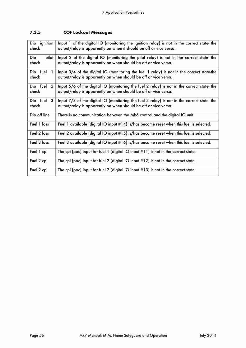
7.3.5 COF Lockout Messages Dio ignition check
Input 1 of the digital IO (monitoring the ignition relay) is not in the correct state- the output/relay is apparently on when it should be off or vice versa.
Dio pilot check
Input 2 of the digital IO (monitoring the pilot relay) is not in the correct state- the output/relay is apparently on when should be off or vice versa.
Dio fuel 1 check
Input 3/4 of the digital IO (monitoring the fuel 1 relay) is not in the correct state-the output/relay is apparently on when should be off or vice versa.
Dio fuel 2 check
Input 5/6 of the digital IO (monitoring the fuel 2 relay) is not in the correct state- the output/relay is apparently on when should be off or vice versa.
Dio fuel 3 check
Input 7/8 of the digital IO (monitoring the fuel 3 relay) is not in the correct state- the output/relay is apparently on when should be off or vice versa.
Dio off line There is no communication between the Mk6 control and the digital IO unit.
Fuel 1 loss Fuel 1 available (digital IO input #14) is/has become reset when this fuel is selected.
Fuel 2 loss Fuel 2 available (digital IO input #15) is/has become reset when this fuel is selected.
Fuel 3 loss Fuel 3 available (digital IO input #16) is/has become reset when this fuel is selected.
Fuel 1 cpi The cpi (poc) input for fuel 1 (digital IO input #11) is not in the correct state.
Fuel 2 cpi The cpi (poc) input for fuel 2 (digital IO input #12) is not in the correct state.
Fuel 2 cpi The cpi (poc) input for fuel 2 (digital IO input #13) is not in the correct state.
7 Application Possibilities
Page 56 Mk7 Manual: M.M. Flame Safeguard and Operation July 2014

7.4 No Pre-purge In the Mk7 M.M. it is possible to allow the burner to start-up as quickly as possible without the need for a pre-purge, i.e. the pre-purge is bypassed. The major advantage of this control means that the overall boiler efficiency is increased by minimising the heat loss to the stack during a purge cycle. This means the burner starts-up quicker therefore reaching setpoint in a reduced time. According to the EN676 European regulation, the burner is allowed to restart without a pre-purge if the burner has recycled due to operational temperature/pressure. When the burner is stopped by a lockout then this procedure is not allowed and the burner will have to start-up in the normal manner with a pre-purge. In order for no pre-purge to be active, valve proving must take place and finish successfully. If this valve proving operation is successful and all of the valves are checked then the burner may start-up without a pre-purge. 7.4.1 Operation In order to initiate the no pre-purge feature, Option and Parameter 143 must be set to a value of 1. During the first start-up the burner will start in the usual manner and a pre-purge will be initiated. Until the complete commissioning program has been entered and the burner started successfully, the burner will start-up every time with the VPS operation and a pre-purge. Once fully commissioned and the burner started successfully then the system will now allow the no pre-purge feature to be initiated. If the burner goes above its setpoint and so turns off in a controlled manner, then the next time the burner starts-up, it will go through the VPS operation and then light off without a pre-purge, i.e. the burner has shutdown in a controlled manner and the gas valves have been checked for integrity. If a lockout occurs or the burner shuts down in an abrupt manner, e.g. loss of power to the unit, then the next time the burner starts-up a complete purge will be initiated. According to the EN 676 regulation, the burner is only allowed to work in this manner if option and Parameter 129 is set to a value of 0, the VPS must operate before the burner starts–up. The start sequence without pre-purge is as follows. Firstly the system goes through its internal tests and relay checks. Call for heat on Terminal 57 activates and the system will go through the VPS operation. If this operation is successful then the M.M. will drive the channels to the light off or start position. Once all channels reach the start position then the burner will light off. It is important to note that this control logic only conforms with European regulations at present and does not conform with NFPA and UL. Note: Pre-purge is only available on fuels 1 and 4 (gaseous).
7 Application Possibilities
July 2014 Mk7 Manual: M.M. Flame Safeguard and Operation Page 57

7.5 Continuous Pilot In the Mk7 M.M. it is possible to enable continuous pilot when the burner goes above its off differential of the required setpoint, then the burner continues to fire with only the pilot valves energised. The continuous pilot feature is now included as standard in the latest software with BC 7.39, please contact Autoflame for more information. 7.5.1 Operation To set up this facility Option 9 must be set to a value of 3 or 4. This means that once the boiler gets up to temperature or pressure, the burner will not switch off but will switch to pilot firing. These additional settings work in the same way as settings 1 and 2 but enable this continuous pilot operation. If Option #9 is set to 3 then the burner goes to pilot firing at an offset above setpoint (set in Option 10) and will switch back to main flame a number of degrees below the setpoint as set in Option 11. If Option 9 is set to 4 then the burner goes to pilot firing at an offset above setpoint (Option 10) and will switch back to main flame a number of degrees above setpoint as set in Option 11. When Option 9 is set to a value of 3 or 4 then an external on/off thermostat or pressure switch must be installed. In the situation when the burner switches back to pilot flame the burner will open the pilot valves and after the second safety time (Option 116), the burner will close its main valves. During the hot standby position the gas pressure is checked by the gas sensor, it is important that the main valves and pilot valves are connected with a small measuring pipeline. When burner is ready to go back to main flame the main fuel valves will open and after the second safety time the pilot valves will be closed and the normal operation will start again. Option 108 sets the offset above the setpoint for the continuous pilot shut-off, and option/parameter 142 sets the continuous pilot shut-off time, where the burner will shutdown and recycle. After x time of continuous pilot, if the main flame is not re-established through load demand, the system will shutdown and recycle.
7 Application Possibilities
Page 58 Mk7 Manual: M.M. Flame Safeguard and Operation July 2014


Autoflame Engineering Ltd Unit1-2 Concorde Business Centre
Airport Industrial Estate, Wireless Road Biggin Hill, Kent TN16 3YN
United Kingdom +44 (0) 845 872 2000 www.autoflame.com