mka-16-03 elec. steer quick release bracket 1854035 · f. take the quick release bracket assembly...
TRANSCRIPT

MKA-16-03 Elec. Steer Quick Release Bracket 1854035
MOUNTING CONSIDERATIONS
TOOLS AND RESOURCES REQUIRED
Complete Typical Installation
Item / Assembly Part # Description Qty.
A 2990114 QCK REL PLATE/THUMB SCREW ASM 1
2 ✖ PLATE-MNT,TOP PD QUICK RELEASE 1
4 ✖ PLATE-MNT,BTM PD/AP QK/RL 1
6 2373421 SCREW-5/16-18 X 3/8 SHCS S/S 1
8 9951778 LOCKWASHER-1/4" ZINC 1
10 2011385 SCREW-TENSION/NEW KNOB 1
p 2374954 INSTR.SHEET MKA-16-03 BULK QRB 1
B 2994932 BAG ASM, ELEC. STEER QRB 1
12 2371728 WASHER-FENDER 1/4 X 1 1/4 ZP 4
14 2373413 SCREW-1/4-20 X 7/8 HHCS ZP 4
16 2263104 NUT-1/4-20 NYLOCK ZP 8
18 2373516 BOLT-1/4-20 X 2" HHC ZP 4
2
6
8
10
4
A
B
1418
12
16
• #3 Phillips Screw Driver• Drill
• 9/32” Drill Bit• 7/16” Box End Wrench
• A second person to help with the installation
It is recommended that the motor be mounted as close to
the centerline of the boat as possible. The motor must not
encounter any obstructions as it is lowered into the water or
raised into the boat when stowed and deployed. Make sure
the motor rest is positioned far enough beyond the edge of
the boat. Make sure the area under the mounting location is
flat, clear to drill holes and install nuts and washers.
p Not shown on Parts Diagram. ✖ This part is included in an assembly and cannot be ordered individually.
minnkotamotors.com | 1 ©2018 Johnson Outdoors Marine Electronics, Inc.
FOR USE WITH ALL MINN KOTA® POWERDRIVE™, PONTOON POWERDRIVE™, ULTERRA™ AND TERROVA® FRESHWATER TROLLING MOTORS & THE POWERDRIVE™ PONTOON HAND CONTROL BRACKET & DECKHAND 40
NOTE: Images are a graphical representation and may vary slightly from your motor.

a. Make sure that the Power Cables from the battery are disconnected, or that the breaker, if equipped, is "off".
1Power Cables
WARNINGMake sure the motor is mounted on a level surface and is not connected to a power source.
INSTALLATION
b. Place the mount on an elevated, level surface such as a workbench or the tailgate of a pickup. The motor should be in the stowed position.
c. Remove the four sideplate screws using a #3 Phillips screwdriver. Two of these screws will be located on each side of the mount.
2
DeployedStowed
Sideplate Screw
2c
minnkotamotors.com | 2 ©2018 Johnson Outdoors Marine Electronics, Inc.
The MKA-16-03 Electric Steer Quick Release Bracket is designed to work on a number of Minn Kota trolling motors. The
base extrusion or mounting bracket of the trolling motors may vary. Please note the appearance of the applicable trolling
motors and mounting brackets.
UlterraPowerDrive Terrova PowerDrive Pontoon Hand Control Bracket
Inboard Inboard Inboard Inboard
DeckHand 40
Inboard
NOTE: A motor may weigh up to 65lbs. We recommend having a second person help with the installation. If mounting to a Pontoon Hand Control Bracket or Deckhand 40, directions specific to motor installation do not apply.

f. Take the Quick Release Bracket Assembly (Item #A) and remove the Tension Screw Knob and Lock Washer. Set the Tension Screw Knob and the Lock Washer aside to reassemble later.
g. Slide the Top Plate and the Bottom Plate and notice the range of motion allowed in the bracket, and the position of the bracket when it is completely closed. The Socket Head Cap Screw stops the motion of the brackets when closed. Slide the plates completely apart and set the Bottom Plate aside.
h. On the Top Plate, take note of the placement of the single Socket Head Cap Screw already attached to the plate. When the Top Plate is attached to the Base Extrusion, the screw will sit under the mount closest to the end where the Power Cord exits the base of the Mount.
4 ITEM(S) NEEDED
#A x 1
CAUTIONWatch for pinch points when sliding the top and bottom plates of the Quick Release Bracket.
minnkotamotors.com | 3 ©2018 Johnson Outdoors Marine Electronics, Inc.
d. Remove the Right Sideplate.
e. Swing the Left Sideplate out and away from the Base Extrusion. Removing the sideplates exposes the mounting holes in the Base Extrusion.
3
3d
3e
Right Sideplate
Mounting Holes
Left Sideplate
Base Extrusion
Tension Screw Knob
Top Plate
Slide
Slide
Top Plate
Bottom Plate
Lock WasherSocket Head
Cap Screw
Power Cord
Socket Head Cap Screw
4f Quick Release Bracket Assembly
4h

k. After the Top Plate is secured to the Base Extrusion, reassemble the Top Plate to the Bottom Plate by sliding it in place and securing with the Lock Washer and Tension Screw Knob.
l. Replace the Right Sideplate.
m. Swing the Left Sideplate back into its correct position on the Base Extrusion.
6
6l
Right Sideplate
6m
Left Sideplate
Base Extrusion
n. Replace the four sideplate screws using a #3 or #2 Phillips screwdriver. Two of these screws will be located on each side of the mount.
Sideplate Screw
minnkotamotors.com | 4 ©2018 Johnson Outdoors Marine Electronics, Inc.
5
i. Take the Top Plate and turn it so the flat side faces upwards. Align the Mounting Holes in the Top Plate with the Mounting Holes in the Base Extrusion that were exposed when the sideplates were removed. Make sure that the Socket Head Cap Screw is located on the mount closest to the Power Cord. The appearance of your Base Extrusion may vary depending on motor type.
j. Use the 1/4 -20 X 7/8 Hex Head Cap Screw (Item #14) and Nylock Nuts (item # 16) to secure the Top Plate to the Base Extrusion. It is recommended to use a minimum of two bolts on each side, placing them the farthest apart on the mount. The screws will pass from the bottom up, through the Top Plate and then the Base Extrusion. The Nylock Nuts are placed on the screws on top of the Base Extrusion and tightened with the 7/16” Box End Wrench. Make sure all hardware is secure.
ITEM(S) NEEDED
#14 x 4 #16 x 4
NOTE: To prevent seizing of hardware, do not use high speed installation tools. Wetting the screws or applying an anti-seize may help prevent seizing.
NOTE: If you are mounting an Ulterra to the Quick Release Bracket, the Clipped Washer that was previously used to install the motor to the boat, or included in the mounting hardware that came with the Ulterra motor should be used. Place the Clipped Washer above the Base Extrusion, between the Base Extrusion and the Nylock Nut. Refer to the Ulterra Owner’s Manual online at minnkotamotors.com for complete details on mounting the Ulterra.
Top Plate
Mounting HolesMounting
Holes
Base Extrusion
Socket Head Cap Screw
Power Cord Exits Here
Hex Head Cap Screw
Nylock Nuts
6n
Outboard
Inboard
8
1-1/2" Minimum
Gunwale
Shaft
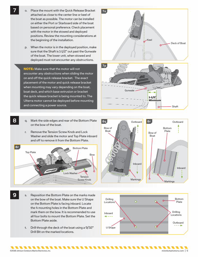
o. Place the mount with the Quick Release Bracket attached as close to the center line or keel of the boat as possible. The motor can be installed on either the Port or Starboard side of the boat based on personal preference. Check placement with the motor in the stowed and deployed positions. Review the mounting considerations at the beginning of the installation.
p. When the motor is in the deployed position, make sure that the Shaft is 1-1/2” out past the Gunwale of the boat. The lower unit, when stowed and deployed must not encounter any obstructions.
7
Deck of BoatKeel
minnkotamotors.com | 5 ©2018 Johnson Outdoors Marine Electronics, Inc.
q. Mark the side edges and rear of the Bottom Plate on the bow of the boat.
r. Remove the Tension Screw Knob and Lock Washer and slide the motor and Top Plate inboard and off to remove it from the Bottom Plate.
s. Reposition the Bottom Plate on the marks made on the bow of the boat. Make sure the U Shape on the Bottom Plate is facing inboard. Locate the 4 mounting holes in the Bottom Plate and mark them on the bow. It is recommended to use all four bolts to mount the Bottom Plate. Set the Bottom Plate aside.
t. Drill through the deck of the boat using a 9/32" Drill Bit on the marked locations.
9Drilling
Locations
Drilling Locations
Bottom Plate
7o
7p
8q 8r
8r
Bow of Boat
Bow of Boat
Outboard
Bottom Plate
Outboard
Markings
Lock WasherTension
Screw Knob
Bottom Plate
Bow
Markings
Inboard
Inboard
Inboard
U Shape
Outboard
Top Plate
NOTE: Make sure that the motor will not encounter any obstructions when sliding the motor on and off the quick release bracket. The exact placement of the motor and quick release bracket when mounting may vary depending on the boat, boat deck, and which base extrusion or bracket the quick release bracket is being mounted to. The Ulterra motor cannot be deployed before mounting and connecting a power source.

u. Put a 1/4-20 X 2” HHC ZP Bolt (Item #18) in each of the four drilled locations. The bolt should pass through the Bottom Plate and the boat deck. Make sure to secure the motor with bolts on each side of the Bottom Plate.
v. Place a Fender Washer (Item #12) and then a Nylock Nut (Item #16) at the end of each bolt as shown and tightened with the 7/16” Box End Wrench. Make sure all hardware is secure.
w. Slide the Top Plate attached to the motor back onto the Bottom Plate that was mounted to the Bow of the boat and secure with the Lock Washer and Tension Screw Knob. Always check the Tension Screw Knob and tighten when needed.
10
11
HHC ZP Bolt
Boat DeckBottom Plate
Fender Washer
Nylock NutBow
NOTE: To prevent seizing of hardware, do not use high speed installation tools. Wetting the screws or applying an anti-seize may help prevent seizing.
ITEM(S) NEEDED
#18 x 4 #12 x 4 #16 x 4
A Johnson Outdoors Company
Minn Kota Consumer & Technical ServiceJohnson Outdoors Marine Electronics, Inc.PO Box 8129Mankato, MN 56001
121 Power DriveMankato, MN 56001Phone (800) 227-6433Fax (800) 527-4464minnkotamotors.com
©2018 Johnson Outdoors Marine Electronics, Inc. All rights reserved.
Part #2374914 Rev J 03/18
For warranty information please visit www.minnkotamotors.com
ECN 39002
NOTE: Lock your motor to help prevent theft.
Lock WasherTension
Screw Knob
Bottom Plate
BowTop Plate
Inboard
Outboard

Support à Dégagement Rapide à Commande Électrique MKA-16-03
1854035
FACTEURS DE MONTAGE
OUTILS ET RESSOURCES NÉCESSAIRES
Installation Complète Typique
Article/Ensemble
Nº de Pièce Description Qté
A 2990114 QCK REL PLATE/THUMB SCREW ASM 1
2 ✖ PLATE-MNT,TOP PD QUICK RELEASE 1
4 ✖ PLATE-MNT,BTM PD/AP QK/RL 1
6 2373421 SCREW-5/16-18 X 3/8 SHCS S/S 1
8 9951778 LOCKWASHER-1/4" ZINC 1
10 2011385 SCREW-TENSION/NEW KNOB 1
p 2374954 INSTR.SHEET MKA-16-03 BULK QRB 1
B 2994932 BAG ASM, ELEC. STEER QRB 1
12 2371728 WASHER-FENDER 1/4 X 1 1/4 ZP 4
14 2373413 SCREW-1/4-20 X 7/8 HHCS ZP 4
16 2263104 NUT-1/4-20 NYLOCK ZP 8
18 2373516 BOLT-1/4-20 X 2" HHC ZP 4
2
6
8
10
4
A
B
1418
12
16
• Tournevis cruciforme nº 3• Perceuse
• Mèche de 9/32 po (7,14 mm)• Clé polygonale de 7/16 po (11,11 mm)
• Une deuxième personne pour vous aider avec l’installation
On recommande de monter le moteur aussi près que possible de l’axe du bateau. Le moteur ne doit rencontrer aucune obstruction lorsqu’il est dans l’eau ou relevé. Assurez-vous que le support du moteur est positionné assez loin du bord du bateau. Vérifiez que la zone sous l’emplacement pour percer des trous et installer des rondelles et des écrous est dégagée et plate.
p Non visible sur le schéma des pièces. ✖ Cette pièce est incluse dans un ensemble et ne peut pas être commandée individuellement.
minnkotamotors.com | 7 ©2017 Johnson Outdoors Marine Electronics, Inc.
À UTILISER AVEC TOUS LES MOTEURS DE PÊCHE À LA TRAÎNE POUR EAU DOUCE MINN KOTA® POWERDRIVE™, PONTOON POWERDRIVE™, ULTERRA™ ET TERROVA®, ET LE SUPPORT À COMMANDE MANUELLE DE POWERDRIVE™ PONTOON ET DECKHAND 40
REMARQUE : les images sont une représentation graphique et peuvent être légèrement différentes de votre moteur.

a. Assurez-vous que les câbles d’alimentation de la batterie sont déconnectés, ou que le disjoncteur, le cas échéant, est en position « arrêt ».
1Câbles d’Alimentation
AVERTISSEMENTAssurez-vous que le moteur est installé sur une surface plane et n’est pas branché à une source d’alimentation.
INSTALLATION
b. Placez le support sur une surface élevée, de niveau, comme un établi ou le hayon d’une camionnette. Le moteur devrait être en position arrimée.
c. Retirez les quatre vis de la plaque latérale en utilisant un tournevis cruciforme nº 3. Deux de ces vis seront situées de chaque côté du support.
2
DéployéArrimé
Vis de Plaque Latérale
2c
minnkotamotors.com | 8 ©2017 Johnson Outdoors Marine Electronics, Inc.
Le support à dégagement rapide à commande électrique MKA-16-03 est conçu pour fonctionner sur plusieurs moteurs de
pêche à la traîne Minn Kota. L’extrusion de la base ou le support de montage des moteurs de pêche à la traîne peut varier.
Veuillez noter l’apparence des moteurs de pêche à la traîne et des supports de montage concernés.
UlterraPowerDrive Terrova Support de la commande manuelle du PowerDrive Pontoon
Intérieur Intérieur Intérieur Intérieur
DeckHand 40
Intérieur
REMARQUE: Un moteur peut peser jusqu’à 65 lb (29,5 kg). Pour l’installation, nous recommandons de vous faire aider par une deuxième personne. Pour un montage du support de la commande manuelle à un Pontoon ou Deckhand 40, les directives spécifiques à l’installation au moteur ne s’appliquent pas.
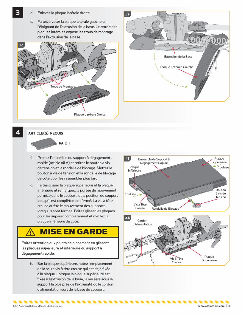
f. Prenez l’ensemble du support à dégagement rapide (article nº A) et retirez le bouton à vis de tension et la rondelle de blocage. Mettez le bouton à vis de tension et la rondelle de blocage de côté pour les rassembler plus tard.
g. Faites glisser la plaque supérieure et la plaque inférieure et remarquez la portée de mouvement permise dans le support, et la position du support lorsqu’il est complètement fermé. La vis à tête creuse arrête le mouvement des supports lorsqu’ils sont fermés. Faites glisser les plaques pour les séparer complètement et mettez la plaque inférieure de côté.
h. Sur la plaque supérieure, notez l’emplacement de la seule vis à tête creuse qui est déjà fixée à la plaque. Lorsque la plaque supérieure est fixée à l’extrusion de la base, la vis sera sous le support le plus près de l’extrémité où le cordon d’alimentation sort de la base du support.
4 ARTICLE(S) REQUIS
#A x 1
MISE EN GARDEFaites attention aux points de pincement en glissant les plaques supérieure et inférieure du support à dégagement rapide.
minnkotamotors.com | 9 ©2017 Johnson Outdoors Marine Electronics, Inc.
d. Enlevez la plaque latérale droite.
e. Faites pivoter la plaque latérale gauche en l’éloignant de l’extrusion de la base. Le retrait des plaques latérales expose les trous de montage dans l’extrusion de la base.
3
3d
3e
Plaque Latérale Droite
Trous de Montage
Plaque Latérale Gauche
Extrusion de la Base
Bouton à vis de Tension
Plaque Supérieure
Coulisse
Coulisse
Plaque Supérieure
Plaque Inférieure
Rondelle de BlocageVis à Tête
Creuse
Cordon d’Alimentation
Vis à Tête Creuse
4f Ensemble de Support à Dégagement Rapide
4h

k. Lorsque la plaque supérieure est fixée à l’extrusion de la base, remontez la plaque supérieure sur la plaque inférieure en la glissant en place et la fixant à l’aide de la rondelle de blocage et le bouton à vis de tension.
l. Replacez la plaque latérale droite.
m. En la faisant pivoter, replacez la plaque latérale gauche dans sa position appropriée sur l’extrusion de la base.
6
6l
Plaque Latérale Droite
6m
Plaque Latérale Gauche
Extrusion de la Base
n. Replacez les quatre vis de la plaque latérale en utilisant un tournevis cruciforme nº 3 ou nº 2. Deux de ces vis seront situées de chaque côté du support.
Vis de Plaque Latérale
minnkotamotors.com | 10 ©2017 Johnson Outdoors Marine Electronics, Inc.
5
i. Prenez la plaque supérieure et tournez-la pour que le côté plat soit vers le haut. Alignez les trous de montage dans la plaque supérieure aux trous de montage dans l’extrusion de la base qui ont été exposés lorsque les plaques latérales ont été retirées. Assurez-vous que la vis à tête creuse est située sur le support le plus près du cordon d’alimentation. L’apparence de votre extrusion de la base peut varier selon le type de moteur.
j. Utilisez la vis à tête creuse hexagonale 1/4 -20 X 7/8 (22,2 mm) (article nº 14) et les écrous Nylock (article nº 16) pour fixer la plaque supérieure à l’extrusion de la base. On recommande d’utiliser au moins deux écrous sur chaque côté, les plaçant le plus loin possible du support. Les vis passeront du bas vers le haut, à travers la plaque supérieure et ensuite l’extrusion de la base. Les écrous Nylock sont placés sur les vis qui sont sur l’extrusion de la base et ensuite serrés à l’aide de la clé polygonale de 7/16 po (11,11 mm). Veillez à ce que toute la quincaillerie soit bien fixée.
ARTICLE(S) REQUIS
#14 x 4 #16 x 4
REMARQUE: Pour éviter la saisie du matériel, n'utilisez pas d'outils d'installation à haute vitesse. Le fait de mouiller les vis ou d’appliquer un antigrippant peut aider à prévenir qu’elles grippent.
REMARQUE: Si vous montez un moteur Ulterra sur le support à dégagement rapide, vous devriez utiliser la rondelle taillée utilisée précédemment pour l’installation du moteur au bateau, ou incluse dans la quincaillerie de montage qui accompagnait le moteur Ulterra. Placez la rondelle taillée au-dessus de l’extrusion de la base, entre l’extrusion de la base et l’écrou Nylock. Consultez le manuel de l’utilisateur Ulterra en ligne à minnkotamotors.com pour les détails complets du montage d’un moteur Ulterra.
Plaque Supérieure
Trous de MontageTrous deMontage
Extrusion de la Base
Vis à Tête Creuse
Le Cordon d’Alimentation
Sort ici
Vis à Tête Creuse
Hexagonale
Écrous Nylock
6n
Extérieur
Intérieur

8
1 1/2 po (3,8 cm) minimum
Plat-bord
Arbre
o. Placez le support en fixant le support à dégagement rapide le plus près possible de l’axe ou la quille. Le moteur peut être installé soit sur le côté bâbord ou tribord du bateau, selon la préférence personnelle. Vérifiez l’emplacement avec le moteur dans la position arrimée et déployée. Relisez les facteurs de montage juste avant l’installation.
p. Lorsque le moteur est en position déployée, veillez à ce que l’arbre dépasse le plat-bord de 1 1/2 po (3,8 cm). L’appareil inférieur lorsque arrimé et déployé ne doit pas rencontrer d’obstacles.
7
Pont du Bateau
Quille
minnkotamotors.com | 11 ©2017 Johnson Outdoors Marine Electronics, Inc.
q. Marquez les bords latéraux et arrière de la plaque inférieure sur la proue de votre bateau.
r. Retirez le bouton à vis de tension et la rondelle de blocage, et faites glisser le moteur et la plaque supérieure vers l’intérieur pour le retirer de la plaque inférieure.
s. Repositionnez la plaque inférieure sur les marques faites sur la proue du bateau. Assurez-vous que la forme en U sur la plaque inférieure fait face vers l’intérieur. Trouvez les quatre trous de montage dans la plaque inférieure et marquez-les sur la proue. On recommande l’utilisation des quatre boulons pour monter la plaque inférieure. Mettez la plaque inférieure de côté.
t. Percez le pont du bateau à l’aide d’une perceuse 9/32 po (7,4 mm) aux endroits marqués.
9 Emplacements de Perçage
Emplacements de Perçage
Plaque Inférieure
7o
7p
8q 8r
8r
Proue du Bateau
Proue du Bateau
Extérieur
Plaque Inférieure
Extérieur
Marques
Rondelle de Blocage Bouton à Vis
de Tension
Plaque Inférieure
Proue
Marques
Intérieur
Intérieur
Intérieur
Forme en U
Extérieur
Plaque Supérieure
REMARQUE: Assurez-vous que le moteur ne rencontrera pas d’obstacles lorsque vous le faites glisser sur le support à dégagement rapide. L’emplacement précis du moteur et du support à dégagement rapide peut varier selon le bateau, le pont du bateau et l’extrusion de la base ou le support auquel est monté le support à dégagement rapide. Le moteur Ulterra ne peut pas être déployé avant le montage et la connexion à une source d’alimentation.

u. Mettez un boulon 1/4-20 x 2 po (50,8 mm) (article nº 18) dans chacun des quatre trous percés. Le boulon devrait traverser la plaque inférieure et le pont du bateau. Assurez-vous de fixer le moteur avec des boulons de chaque côté de la plaque inférieure.
v. Mettez une rondelle de protection (article nº 12) et ensuite un écrou Nylock (article nº 16) à chaque extrémité de chaque boulon, selon l’illustration, et serrez avec une clé polygonale de 7/16 po (11,11 mm). Veillez à ce que toute la quincaillerie soit bien fixée.
w. Faites glisser la plaque supérieure fixée sur le moteur sur la plaque inférieure qui a été montée à la proue du bateau et fixez-la avec une rondelle de blocage et un bouton à vis de tension. Vérifiez toujours le bouton à vis de tension et serrez-le au besoin.
10
11
Boulon HHC ZP
Pont du BateauPlaque Inférieure
Rondelle de Protection
Écrou NylockProueREMARQUE : Pour éviter la saisie du matériel, n'utilisez pas d'outils d'installation à haute vitesse. Le fait de mouiller les vis ou d’appliquer un antigrippant peut aider à prévenir qu’elles grippent.
ARTICLE(S) REQUIS
#18 x 4 #12 x 4 #16 x 4
A Johnson Outdoors Company
Minn Kota Consumer & Technical ServiceJohnson Outdoors Marine Electronics, Inc.PO Box 8129Mankato, MN 56001
121 Power DriveMankato, MN 56001Phone (800) 227-6433Fax (800) 527-4464minnkotamotors.com
©2018 Johnson Outdoors Marine Electronics, Inc. All rights reserved.
Part #2374914 Rev H 06/17
Pour plus d’informations sur la garantie, veuillez visiter le www.minnkotamotors.com
ECN 38128
REMARQUE: Verrouillez votre moteur pour éviter le vol!
Rondelle de Blocage Bouton à
Vis de Tension
Plaque Inférieure
ProuePlaque Supérieure
Intérieur
Extérieur