mkii - davey water products · 2 35 davey commenced in 1934 and today, as davey water products,...
TRANSCRIPT

For any assistance or after sales service contact your Davey Dealer. For help in locating your closest dealer contact your appropriate Davey Support Centre listed on the back of this booklet.
• InstallatIon• operatIon• trouble shootIng
InstallatIon InstructIons
3 YEARS GU
AR
AN
TEE ON ALL RAINBA
NK
S 3YEARS
MKII
2009 WINNER
ATS 5200.446 Lic WMKA 22042
AUSTRALIA
Davey Support Centre6 Lakeview Drive,Scoresby, Australia 3179Ph: 1300 367 866Fax: 1300 369 119Website: davey.com.auDavey Water Products Pty Ltd
Member of the GUD GroupABN 18 066 327 517
NEW ZEALAND
Davey Support Centre7 Rockridge Avenue,Penrose, Auckland 1061Ph: 0800 654 333Fax: 09 527 7654Website: daveynz.co.nz
® Davey and RainBank are registered trade marks of Davey Water Products Pty Ltd.© Davey Water Products Pty Ltd 2013. P/N 401336-11 supersedes P/N 401336-10
2 35
Davey commenced in 1934 and today, as Davey Water products, manufactures and distributes a comprehensive range of products for transfer, conservation, treatment and filtration of water.
Davey has a dominant market share in australia and exports to more than 50 separate countries, servicing some of the toughest environmental and climatic conditions on the globe.
Davey has maintained its commitment to research and development, resulting in innovative new products servicing specific and emerging market opportunities. Many of these products have received multiple awards for innovation and excellence which have led to our induction into the Manufacturing hall of Fame in Victoria.
Davey maintains leadership in quality with an environmental focus by holding Iso 9000-2001 accreditation and Iso 14000 environmental standard.
Davey is today a wholly owned subsidiary of guD, a ‘top 200’ australian public company whose shares are listed on the australian stock exchange.
now more than ever “Depend on Davey” reflects a business culture of dependable, innovative water solutions when and where you need them, supported by the best service and advice.
DaVeY guarantee
* Installation and operating instructions are included with the product when purchased new. They may also be found on our website.
Davey® Repair or Replacement GuaranteeIn the unlikely event in Australia or New Zealand that this Davey product develops any malfunction within warranty periods beginning from the date of original purchase due to faulty materials or manufacture, Davey will at our option repair or replace it for you free of charge, subject to the conditions below.
Should you experience any difficulties with your Davey product, we suggest in the first instance that you contact the Davey Dealer from which you purchased the Davey product. Alternatively you can phone our Customer Service line on 1300 367 866 in Australia, or 0800 654 333 in New Zealand, or send a written letter to Davey at the address listed below. On receipt of your claim, Davey will seek to resolve your difficulties or, if the product is faulty or defective, advise you on how to have your Davey product repaired, obtain a replacement or a refund.
Your Davey Guarantee naturally does not cover normal wear or tear, replacement of product consumables (i.e. mechanical seals, bearings or capacitors), loss or damage resulting from misuse or negligent handling, improper use for which the product was not designed or advertised, failure to properly follow the provided installation and operating instructions, failure to carry out maintenance, corrosive or abrasive water or other liquid, lightning or high voltage spikes, or unauthorized persons attempting repairs. Where applicable, your Davey product must only be connected to the voltage shown on the nameplate.
Your Davey Guarantee does not cover freight or any other costs incurred in making a claim. Please retain your receipt as proof of purchase; you MUST provide evidence of the date of original purchase when claiming under the Davey Guarantee.
Davey shall not be liable for any loss of profits or any consequential, indirect or special loss, damage or injury of any kind whatsoever arising directly or indirectly from Davey products. This limitation does not apply to any liability of Davey for failure to comply with a consumer guarantee applicable to your Davey product under the Australian or New Zealand legislation and does not affect any rights or remedies that may be available to you under the Australian or New Zealand Consumer Legislation.
In Australia, you are entitled to a replacement or refund for a major failure and for compensation for any other reasonably foreseeable loss or damage. You are also entitled to have the goods repaired or replaced if the goods fail to be of acceptable quality and the failure does not amount to a major failure.
Should your Davey product require repair or service after the guarantee period; contact your nearest Davey Dealer or phone the Davey Customer Service Centre on the number listed below.
For a complete list of Davey Dealers visit our website (davey.com.au) or call:
Davey Guarantee Period
RainBank Controller - Three Years Pump - Two Years

34 3
contents
about rainbank® . the easy way to save water. 4
two types of installation - quick reference 5
how rainbank® works 6
how to install rainbank® 7
before you start 9
Installation instruction 11
pump outside tank option 12
pump inside tank option 14
Float switch installation 18
Installation of submersible pumps 25
priming pumps 26
Maintaining rainbank® 28
trouble shooting rainbank® 29
Warnings 32
plumbers tips 33
Davey guarantee 35
contact Details 36
notes

m5 m5
m4
100,000 Litres4 33
congratulations on your purchase of a high quality australian made Davey rainbank® automatic water controller. rainbank® is patented and has been fitted to thousands of homes.
• rainbank® allows you to use water from your rainwater tank for your toilet, washing machine or garden whenever there is water in the tank.
• If the tank water is exhausted rainbank® automatically and seamlessly switches you over to mains water.
• rainbank® has an in-built “dual check valve” for low hazard back flow prevention.
RainBank® can save up to 40% of your home’s usage of mains water, which could be up to 100,000 litres of water a year.
Your actual savings depend on your roof catchment area, rainfall and the size of your tank.
RainBank® may allow you to claim tank rebates (when installed on existing homes). Check with your local water authority.
In some areas of australia, having a rainbank® and using rainwater for your toilet and washing machine allows you to claim tank rebates paid by state governments and some councils.
RainBank® is energy efficient and cheap to run.
because rainbank® only works when it is needed it uses very little energy.
the daily power used to run a rainbank® and pump system supplying two toilets in a three person dwelling is equivalent to:
• a reverse cycle air conditioner for 3 minutes
• a clothes dryer for 3 minutes
• a washing machine for 10 minutes
• a tV or pc for 30 minutes
about raInbank® the easY WaY to saVe Water pluMbers tIps
1. Install pump on a level, solid, well drained site (this will reduce noise and pipe stress).
2. Fit first flush devices to all down pipes to ensure clean water inside the tank (dirty tank water can stain toilets & clothes).
3. clear swarf from all pipes and holes drilled into the tank (swarf can block valves, rainbank® and toilet valves). Fit a 200 micron ‘Y’ strainer before the pump or between the pump and rainbank.
4. Fit a stop valve on mains water line before rainbank (makes servicing easier).
5. Fit a stop valve between pump and tank outlet (makes servicing easier).
6. check with local council plumbing teams for backflow requirements.
7. keep pipe work well braced as vibrations can become noisy.
8. Fill rainwater tank above float switch with garden hose to check system.
9. Make sure pump is full of water (primed) before leaving site. Flush all air outof system by running pump with an outlet downstream open.
protect from the weather Don’t create air locks!
Fit isolation valves prime pump before switching on
6
6
1
2
5
1
2
3
In-t
ank O
pti
on M
od
el N
o. K
RB
S1&
2
3
5
6
9
4
7 Ab
ove
Gro
un
d O
pti
on
M
od
el N
o. K
RB
1,2
,3&
4
9
4
Mai
ns w
ater
sup
ply
90
0kPa
Max
imum
1
3/4”
BSP
Mal
e th
read
2
3/4”
BSP
Mal
e th
read
3
Pum
p P
ower
lead
4
Rain
Bank
® P
ower
lead
5
Stop
val
ve
War
nin
g:
Do
not
reco
nnec
t w
ithm
ains
wat
er s
upp
ly
Imp
ort
ant:
All
pip
ewor
k an
d ou
tlet
fittin
gs fr
om R
ainB
ank®
mus
tbe
labe
lled
to A
S/N
ZS
3500
6
Floa
t sw
itch
7
Man
ual s
tart
but
ton
8
Rain
wat
er s
upp
ly v
ia p
ump
9
8
8
32 5
WarnIngs
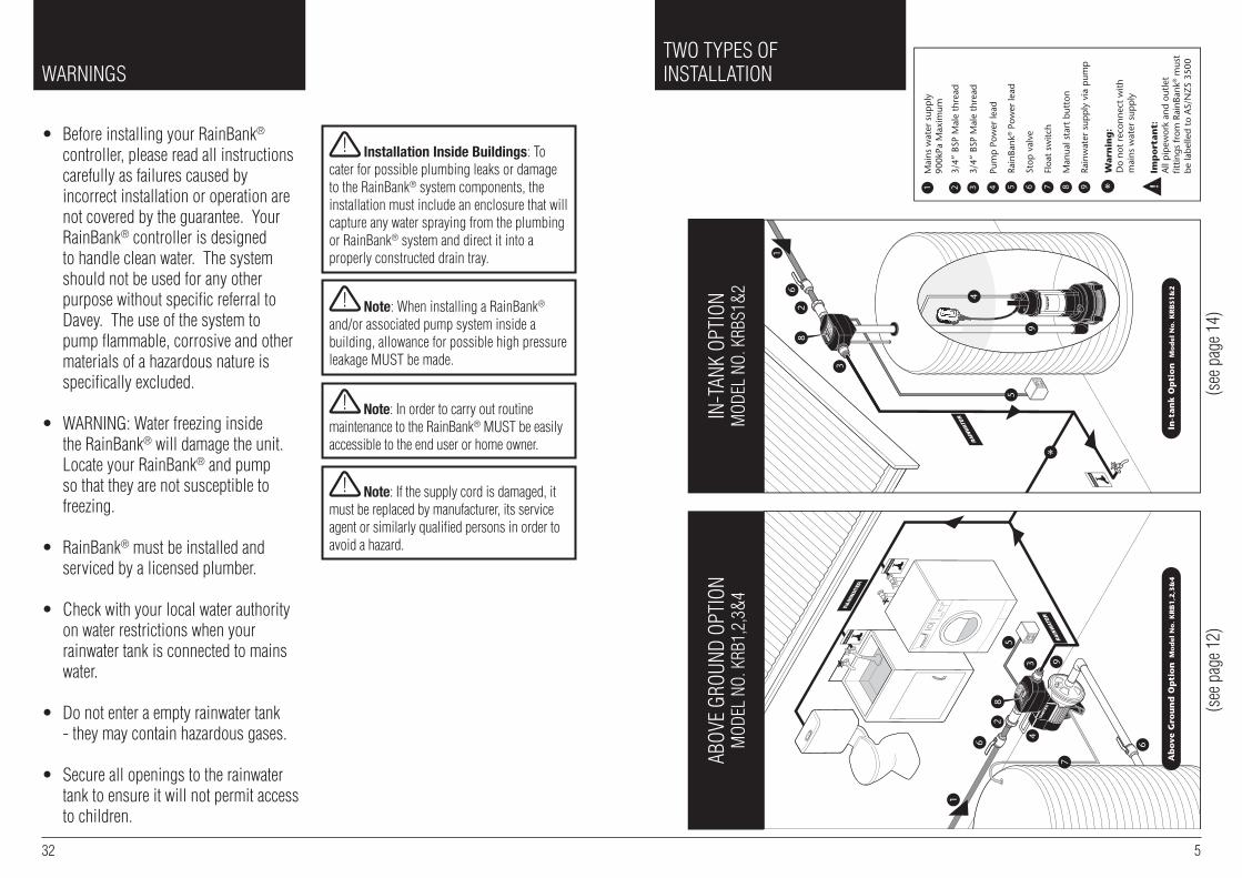
• before installing your rainbank® controller, please read all instructions carefully as failures caused by incorrect installation or operation are not covered by the guarantee. Your rainbank® controller is designed to handle clean water. the system should not be used for any other purpose without specific referral to Davey. the use of the system to pump flammable, corrosive and other materials of a hazardous nature is specifically excluded.
• WarnIng: Water freezing inside the rainbank® will damage the unit. locate your rainbank® and pump so that they are not susceptible to freezing.
• rainbank® must be installed and serviced by a licensed plumber.
• check with your local water authority on water restrictions when your rainwater tank is connected to mains water.
• Do not enter a empty rainwater tank - they may contain hazardous gases.
• secure all openings to the rainwater tank to ensure it will not permit access to children.
aboV
e gr
ounD
opt
Ion
MoD
el n
o. k
rb1,
2,3&
4In
-tan
k op
tIon
MoD
el n
o. k
rbs1
&2
tWo tYpes oFInstallatIon
(see
pag
e 12)
(see
pag
e 14)
! Installation Inside Buildings: to cater for possible plumbing leaks or damage to the rainbank® system components, the installation must include an enclosure that will capture any water spraying from the plumbing or rainbank® system and direct it into a properly constructed drain tray.
! Note: When installing a rainbank® and/or associated pump system inside a building, allowance for possible high pressure leakage Must be made.
! Note: In order to carry out routine maintenance to the rainbank® Must be easily accessible to the end user or home owner.
! Note: If the supply cord is damaged, it must be replaced by manufacturer, its service agent or similarly qualified persons in order to avoid a hazard.
6 31
hoW raInbank® Works
1. When there is demand for water from your toilet, washing machine or garden tap, rainbank® senses this demand and checks the level of water in the rainwater tank. note: demand must be greater than 1.5 litres per minute or mains water will be delivered.
2. If there is rainwater in the tank rainbank® switches on the pump. the pressure of the pump is sufficient to overcome the pressure of the mains water inside rainbank® and this moves a plunger and allows the rainwater to flow. note: mains water pressure is not restricted.
3. When there is no longer a demand for water, rainbank® detects that water has ceased to move inside the pipes, switches off the pump and waits for another water demand.
4. If rainbank® senses a water demand and detects insufficient water in the rainwater tank it will automatically allow the mains water to flow.
5. If there is a power failure during a demand for water rainbank® will automatically supply the mains water as backup.
What are the advantages of RainBank® over conventionalair-gap systems?
• rainbank® is totally hands off and needs no maintenance or adjustment.
• rainbank® is easy to install.
• rainbank® does not require mains water to be re-pumped and therefore saves energy.
• rainbank® is WaterMark approved - this means plumbing inspections will be approved & your plumbers insurance should cover installation faults.
• rainbank® will provide mains water as backup when: - there is no rainwater - there is no electricity to run pump - the pump has been removed for servicing. air-gap systems rely on pumps to pressurise all water and do not function without them.
Mains water is still in use when pump is running. possible cause - pump needs to be primed. stop pump and remove priming plug from front top of pump (right above water inlet) and allow all air to escape from pump. replace the priming plug when water dribbles out of hole (see page 26).
Mains water is still in use when pump is running. possible cause - debris is caught inside rainbank preventing plunger mechanism from sealing completely. contact your plumber to fit a ‘Y’ strainer to system between tank & rainbank.
Mains water is still in use when pump is running. possible cause - pump impeller blocked. have pump serviced. Fit first flush devices and ‘Y’ strainer to pipework.
Mains water not passing through RainBank®. possible cause - rainbank®
installed backwards. Install rainbank® according to installation & operating instructions. arrow on top of rainbank indicates direction of flow.
Mains water not passing through RainBank®. possible cause - debris is blocking inlet to rainbank®. remove rainbank® and clean inlet. check all filters are clean.
Mains water pressure and flow too low. possible cause - there is a check valve or prV installed between rainbank® and tank. remove check valve or prV from plumbing. check all filters in plumbing are clean.
Pump hums. possible cause - pump is jammed or seized. have pump serviced.
Water leaking from connection between pump and RainBank®. possible cause - installer has failed to fit connection kit correctly. remove rainbank® and re-install connection kit.
Mains water filling up tank. possible cause - debris caught inside rainbank®. Install first flush devices and ‘Y’ strainer.
Green light flashing. boot-up sequence only.
Red light flashing. pump has lost prime and needs to be filled with water, see page 26. pump will automatically retry at: 1, 5, 30, 60 and 120 minute intervals.
Pump takes 10 seconds to start. this is anti-cycling software that allows 1 start every 10 seconds.
OTHER SYMPTOMS:

IMPORTANT because it involves mains water, rainbank® may only be legally installed by a licensed plumber. ensure mains water pressure is limited to 900kpa.
note: because the effects of seasonal change etc. can cause the pump and tank to move slightly relevant to the home it is highly recommended that discharge and/or suction pipe lines be fitted with flexible pipe, such as braided hose, reinforced suction hose or polythene pipe.
Different types of RainBank® Installations
there are different ways a rainbank® can be installed depending on your rainwater tank and pump configuration.
INSTAllATION TYPE 1 - PAgE 16
Tank: above groundPump: outside tankFloat switch: must be installed insideof tankPump Kit: krb1,2,3&4
INSTAllATION TYPE 2 - PAgE 21
Tank: above groundPump: submersible inside tankFloat switch: incorporated with pumpPump Kit: krbs1&2
INSTAllATION TYPE 3 - PAgE 22
Tank: below groundPump: submersible inside tankFloat switch: incorporated with pumpsPump Kit: krbs1&2
Mains InTo House
Mains InTo House
FS
30 7
1. Pump not plugged in. plug pump into base of rainbank® and rainbank® into power supply. see page 20.
2. No power supply to pump. contact electrician and have power restored.
3. Float switch not connected to RainBank®. plug float lead into base of rainbank®. the connection lead is located next to the power lead coming from the rainbank®. to confirm the connection is correct, depress ‘manual override’ button, pump will start.
4. No water in tank. check water level in tank.
5. Float switch located at water tank is installed incorrectly. check position of float. see page 16-19.
6. Mains water supply not connected to RainBank. rainbank® system must have a pressurised water supply connected to inlet. press ‘manual override’ button to simulate mains water flowing.
7. Mains supply to RainBank®
turned off. turn on mains water supply. press ‘manual override’ button to simulate mains water flowing. pump will start is rain water is available.
8. Pump is faulty. to confirm if the fault is within the pump, plug the pump directly into power point and check to see if it starts. If the pump starts plug the pump back into the rainbank® and continue fault finding. If the pump does not start contact your supplier for further advice.
9. Lead from float switch to pump broken or damaged. replace float and lead assembly.
10. Float switch defective. contact your supplier for further advice.
11. Mains water flow is too low. ensure flow at most distant outlet is above 5 litres per minute.
SYMPTOM: PUMP WIll NOT SWITCH ON hoW to Install raInbank®
!
Mains InTo House

1. Pump plugged directly into power outlet. plug lead from pump into base of rainbank® as per installation instructions on pg 20.
2. Water is still being used. check all taps, toilets and appliances connected to rainbank® system to ensure they are turned off.
3. Water is leaking on discharge side of RainBank® system. check for leaks and repair.
4. Rock or debris caught inside RainBank®. call your plumber to fit a Y strainer - rainbank® will need to be returned to Davey.
8 29
trouble shootIngraInbank®
SYMPTOM: PUMP WIll NOT SWITCH OFF
INSTAllATION TYPE 4 - PAgE 23
Tank: below ground and at ground levelFloat switch: top entryPump Kit: krb1,2,3&4
Different ways of installing the RainBank® unit itself.
• exposed installation against wall (under eaves).
• encased installation with unit and pump inside cover.
• Integrated installation incorporated as part of tank system.
FV
Mains InTo House
To HouseMains In
To House
Mains In
To House
Mains In

rainbank® does not need maintenance but there are things you can do to ensure its most reliable operation.
• Fit a “first flush” system that ensures the first run of dirty rainwater does not go into the tank.
• clean your gutters and first flush devices and ‘Y’ strainers regularly.
• remove branches that over hang your roof.
• have a strainer fitted to your rainwater tank inlet and regularly check this for leaves and twigs, etc.
• You should also check for debris in the bottom of your tank a few times a year and clean this out if necessary. a first flush system will greatly reduce the need for this action.
IMPORTANT MAINTENANCE PRECAUTIONS• Davey pump motors are fitted with an automatic thermal overload switch that stops the motor if the motor gets too hot to avoid damaging it. this automatically re-starts the motor when the temperature within the pump has dropped to a safe level. constant tripping of this switch indicates a problem e.g. low voltage at pump, etc.
• this automatic thermal overload switch can start the pump without warning. always disconnect the controller and/or pump motor from the electrical supply before maintenance or repairs.
• care should also be taken when servicing or disassembling pump to avoid injury from hot pressurised water. unplug the pump, relieve the pressure by opening a tap on the discharge side of the pump and allow any hot water to cool before attempting to dismantle.
• Do not use petroleum based fluids or solvents (e.g. oils, kerosene, turpentine, thinners, etc on the plastic or seal components).
• Do not use hydrocarbon based or propelled sprays around the electrical components of the controller.
• During servicing use only approved non petrochemical based oring and gasket lubrication. If unsure consult your Davey dealer for advice.
!
28 9
beFore You start
IMPORTANT:• If you are in doubt about any aspect of your rainbank® kit’s suitability, check with your Davey dealer. For help in locating your closet dealer call the appropriate Davey customer service centre listed on the back of this booklet.
• rainbank® is designed to handle clean rainwater and mains water. It should not be used to interconnect as part of a bore water, dam water, grey water, stormwater or recycled water system without appropriate additional back flow.
• Make sure the wiring, plumbing and the rainbank® unit are protected from access by children and pets.
Other things we recommend to maximise the performance and serviceability of your RainBank®.
• Fit a first flush system to the guttering if possible to divert the initial run of water from the roof that may contain dirt and pollutants.
• Fit a strainer to the top of your tank inlet to stop leaves entering the system.
• Fit a 1 inch ‘Y’ strainer with 200 micron mesh to the pipe work between the pump and rainbank®. this will ensure that debris from the tank will not build up inside rainbank®, washing machines or toilet cisterns.
• use at least 20mm or 3 ⁄4 inch plumbing to and from rainbank® to reduce the effect of pipe friction. galvanised pipe not recommended.
!
MaIntaInIng raInbank®

10 27
Make sure the delivery from rainbank® to your home is within the following pipe length limits:
pipe Max. pipe Max. pipe diameter length @ length @ 6 lpm flow 12 lpm flow 15mm 1m 1m 18mm 90m 27m 20mm 235m 135m
For each bend or tee you should reduce the above distances by 0.5m.
• We recommend fitting isolation valves to the rainwater and mains water pipe so that the rainbank® can be easily and conveniently removed if required. this saves both wasting rainwater and having to turn off the mains supply if the unit ever has to be removed.
• While rainbank® does have an in-built Dual check back flow prevention valve, some water authorities require an additional external back flow valve to be plumbed into the mains water delivery line, to prevent any possible contamination of mains water by rainwater, particularly if the tank is partially or fully submerged. check with your local water authority for their plumbing guidelines on rainwater tanks.
• Double check valve assemblies are available from Davey and should be installed if the tank is partially or fully buried.
• Mains water must be limited to below 900kpa.
Type 4 installations. External suction pump drawing from below ground tank.
pump inlet should be at least (200mm) below the lowest water level for reliable operation.
priming is as for type 1 installations.If there is a significant amount of water required to do this it can be a good idea to fit the highest area of the pipe with an access plug in a t piece so that the pipe can be filled more quickly with a bucket when repriming.

26 11
InstallatIon InstructIons
Things you should be aware of:
• before installing rainbank® please read all instructions carefully as failures caused by incorrect installation are not covered under warranty.
• rainbank® is designed to handle clean water and should not be used for any other purpose without specific referral to Davey. the use of rainbank® to pump flammable, corrosive or other materials of a hazardous nature will damage the system and void the warranty.
• the pumping of abrasive materials will damage the system and void the warranty.
• Water freezing inside the rainbank® will damage the unit. locate your rainbank® and pump so that they are not susceptible to freezing.
• some insects such as small ants find electrical devices attractive for various reasons. If your controller or pump is susceptible to insect infestation you should implement a suitable pest control plan.
• limit mains water pressure to 900kPa.
• an inline ‘Y’ strainer between the pump and the rainbank® controller is
recommended to stop foreign matter entering the unit and damaging it.
• all pipe work and fittings should be labelled in accordance with local
standards such as australian standard as/nZs 3500. this standard
requires that all pipework containing rainwater is marked with green ‘rainwater’ tape or stickers at 1 meter intervals and every outlet that may deliver rainwater is to be permanently signed with ‘rain Water’
signage or a green tap marked ‘rW’.
• ensure all wiring, plumbing and the rainbank® unit are protected from access by pets and/or children.
• Mains electrical connections and checks must be made by a qualified electrician and comply with applicable local standards. the 5 volt float lead connections need not be carried out by a qualified electrician, but should be done in compliance with applicable standards.
• In accordance with as/nZs 60335.2.41 we are obliged to inform you that this controller and any pump controlled by it is not to be used by children or infirm persons and must not be used as a toy by children.
Type 1 installations. Above ground tank and pump outside tank.
1. remove the priming plug on the top of the pump and fill the casing and suction line with water then refit plug. If there is an isolation valve fitted on the delivery pipe from the rainwater tank (as recommended) this needs to be opened.
If there is an air lock i.e. the pipe and pump casing is not fully filled with water, the pump may not draw water. If this is the case you should repeat the priming procedure. If the pump still does not draw properly this may be a fault in the way the delivery pipe is installed. the pump should be slightly higher than the pipe inlet and this should run up hill to the pump at a slight but consistent slope so that any air is expelled at the pump end as the pump is primed.
2. hold down ‘manual override’ button on the rainbank to operate pump to clear trapped air. Make sure an outlet (tap) is open so that air and water can be dispelled. Make sure the mains water is turned off until the pump is fully primed.
IMPORTANTleaky joins can also cause a loss of prime.note: the pump must be below the float switch.
Type 2 and 3 installations. Submersible pumps inside tank.
provided the pump is sitting in sufficient water the pump will self prime and push air out of the taps and appliances that are used at the other end. to let this air out without causing damage it is important that:
• all taps connected to the rainwater system are turned on
• toilets connected to the system are flushed so the cistern fills and any air is cleared from the line.
prIMIng puMps
!
6
6
1
2
5
1
2
3
In-tank Option Model No. KRBS1&2
3
5
6
9
4
7
Above Ground Option Model No. KRB1,2,3&4
9
4
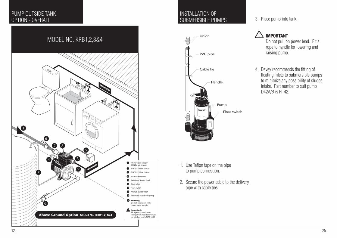
Mains water supply 900kPa Maximum
1
3/4” BSP Male thread2
3/4” BSP Male thread3
Pump Power lead4
RainBank® Power lead5
Stop valve
Warning:Do not reconnect withmains water supply
Important:All pipework and outletfittings from RainBank® mustbe labelled to AS/NZS 3500
6
Float switch7
Manual start button8
Rainwater supply via pump9
8
8
12 25
puMp outsIDe tank optIon - oVerall
MoDel no. krb1,2,3&4
InstallatIon oF subMersIble puMps
1. use teflon tape on the pipe to pump connection.
2. secure the power cable to the delivery pipe with cable ties.
3. place pump into tank.
4. Davey recommends the fitting of floating inlets to submersible pumps to minimize any possibility of sludge intake. part number to suit pump
D42a/b is FI-42.
Cable tie
PVC pipe
Union
Float switch
Pump
Handle
! IMPORTANTDo not pull on power lead. Fit a rope to handle for lowering and raising pump.
6
6
1
2
5
1
2
3
In-tank Option Model No. KRBS1&2
3
5
6
9
4
7
Above Ground Option Model No. KRB1,2,3&4
9
4
Mains water supply 900kPa Maximum
1
3/4” BSP Male thread2
3/4” BSP Male thread3
Pump Power lead4
RainBank® Power lead5
Stop valve
Warning:Do not reconnect withmains water supply
Important:All pipework and outletfittings from RainBank® mustbe labelled to AS/NZS 3500
6
Float switch7
Manual start button8
Rainwater supply via pump9
8
8

RA
INW
AT
ER
SU
PP
LYfr
om d
isch
arge
of r
ainw
ater
pum
p
Pow
er to
pum
p vi
a3
pin
sock
et -
plu
g th
era
inw
ater
pum
p in
her
e.
1" B
SP
M
200m
m20
0mm
TO
TO
ILE
TS
AN
D/O
RL
AU
ND
RY
(do
not m
ix/c
ross
-con
nect
with
mai
ns w
ater
sup
ply)
* P
ress
ure
Lim
itin
g V
alve
MA
INS
WA
TE
R S
UP
PLY
3/4"
BS
P M
Inco
min
g po
wer
to R
ainB
ank®
via
3 pi
n pl
ug
3/4"
BS
P M
Sto
p va
lve
200
Mic
ron
‘Y’ S
trai
ner
reco
mm
ende
d bu
t not
supp
lied.
WH
ER
E M
AIN
S P
RE
SS
UR
E E
XC
EE
DS
900
kPa.
A P
LV
* MUST
BE
FIT
TE
D T
O IN
LE
T!
Rai
nB
ank®
MUST
BE
INS
TA
LL
ED
HO
RIZ
ON
TA
LL
Y A
S IL
LU
ST
RA
TE
D.
Sto
p va
lve
20m
m h
ole
puMp outsIDe tank optIon - close up
24 13
Step 3 – plumb up your suction plumbing ensuring that the lowest point in the inlet pipe is at least 200mm below the lowest water level and at least 100mm above the base of the tank.
Step 4 – Install the float switch. check that the float switch lead (9m long) will reach the rainbank®. For greater distances between your rainwater tank and pump, a 10m float switch (top and side entry) extension lead (Davey part no. 14186) will need to be added. up to 4 float switch extension leads can be added between the pump and the rainwater float switch lead. It is recommended that the float switch extension lead/s are in a protective cinduit.the float end should be set up so it can fall no lower than 100mm above the level of the lowest point in the inlet pipe so the pump will always be shut off well before it can run dry or draw in air.
this is secured to the pump suction pipe with cable ties. allow no more than 100mm of cable between the float and the lowest cable tie.
the plug end should be plugged into the float switch inlet on the underside of the rainbank® unit in step 8.
Step 5 – align the rainbank® for easy fitting to the plumbing.
Step 6 – connect rainbank® to the pump.
Step 7 – connect rainbank® to the plumbing.
Step 8 – connect all leads.
Step 9 – test the unit - page 21.
WA
RN
ING
: DO
NO
T F
IT C
HE
CK
VA
LVE
S B
ET
WE
EN
RA
INB
AN
K®, P
UM
P
AN
D T
AN
K, U
NLE
SS
PU
MP
IS A
BO
VE
MA
XIM
UM
WA
TE
R L
EV
EL
OF
TA
NK
.
IMPORTANT: ALL PIPEWORK AND OUTLET FITTINGS FROM RAINBANK® MUST BE LA-BELLED TO AS3500. TANK MUST HAVE ISOLATION VALVE FITTED. DO NOT CONNECT WITH CRIMPED FITTINGS.
100
100
100
100
C
D
E
F
A
D
E
B
A
D
E
B

6
6
1
2
5
1
2
3
In-tank Option Model No. KRBS1&2
3
5
6
9
4
7
Above Ground Option Model No. KRB1,2,3&4
9
4
Mains water supply 900kPa Maximum
1
3/4” BSP Male thread2
3/4” BSP Male thread3
Pump Power lead4
RainBank® Power lead5
Stop valve
Warning:Do not reconnect withmains water supply
Important:All pipework and outletfittings from RainBank® mustbe labelled to AS/NZS 3500
6
Float switch7
Manual start button8
Rainwater supply via pump9
8
8
puMp InsIDe tankoptIon - oVerall
MoDel no. krbs1&2
14 23
You should carry out the following steps as per the instructions for Installation Type 1
Step 2 – Work out the position of your rainbank® with regard to distance to power. the float switch lead is not an issue here.
Step 4 – align the rainbank® for easy fitting to the plumbing. Fit Davey wall bracket.
Step 5 – connect rainbank® to your submersible pump as per instructions on page 25.
Step 6 – connect the rainbank® to the plumbing.
Step 7 – connect all leads (no float switch lead to plug in)
Step 8 – test the unit - page 21
INSTAllATION TYPE 4Below ground tank with pump above tank and suction lift
IMPORTANT• under australian standard 3500 collecting/storing rainwater in a partially buried tank is considered a medium level hazard. even though rainbank® has a built-in dual check back flow valve you may be required to fit additional backflow protection valves to satisfy this requirement.
note: to allow for the correct operation of your rainbank® and for movement of the tank and pump which may occur over time, the suction pipe must have a length of flexible suction hose from pump to top of tank. this hose can be braided hose, reinforced suction hose or polythene pipe at least 1 metre in length.
The following sections of the Type 1 installation instructions are applicable to Type 4 installations.
Step 1 – evaluate and select the best pump site as close to the water source and water level as possible.
Step 2 – Work out the position of your rainbank® with regard to distance to power.
!
6
6
1
2
5
1
2
3
In-tank Option Model No. KRBS1&2
3
5
6
9
4
7
Above Ground Option Model No. KRB1,2,3&4
9
4
Mains water supply 900kPa Maximum
1
3/4” BSP Male thread2
3/4” BSP Male thread3
Pump Power lead4
RainBank® Power lead5
Stop valve
Warning:Do not reconnect withmains water supply
Important:All pipework and outletfittings from RainBank® mustbe labelled to AS/NZS 3500
6
Float switch7
Manual start button8
Rainwater supply via pump9
8
8
FV
Mains InTo House

22 15
• Failure to prime the submersible pump prior to connection of the pump to rainbank® can cause an air lock that may prevent the pump operating properly.
The following sections of the Type 1 installation instructions are applicable to Type 2 installations.
Step 2 – Work out the position of your rainbank® with regard to distance to power. the float switch lead is not an issue here.
Step 4 – align the rainbank® for easy fitting to the plumbing and fit Davey wall bracket if required.
Step 5 – connect rainbank® to your submersible pump as per instructions on page 25.
Step 6 – connect the rainbank® to the plumbing as for Installation type 1 on page 19.
Step 7 – connect all leads as per Installation type 1 on page 20. there is no float switch lead as this is fitted to the submersible pump.
Step 8 – test the unit - page 21.
INSTAllATION TYPE 3below ground tank with submersible pump D42a/b & D53a/b
IMPORTANT• under australian standard 3500 collecting/storing rainwater in a partially buried tank is considered a medium level hazard. even though rainbank® has a built-in dual check back flow valve, you may be required to fit additional backflow protection valves to satisfy this requirement – check with your local council as to their guidelines on rainwater tank installation and backflow prevention.
there is no need for a separate float switch as this comes attached to the submersible pump and does not plug into the rainbank® unit.
!
puMp InsIDe tankoptIon - close up
TOTO
ILET
SA
ND
/OR
LAU
ND
RY(d
o no
t mix
/cro
ss-c
onne
ctw
ith m
ains
wat
er s
uppl
y)
MA
INS
WAT
ER S
UPP
LY
3/4"
BS
P M
RA
INW
ATER
SUPP
LYfro
m d
isch
arge
of a
uto
subm
ersi
ble
rain
wat
er p
ump
Pow
er to
pum
p vi
a3
pin
sock
et -
plug
the
rain
wat
er p
ump
in h
ere.
Inco
min
g po
wer
to R
ainB
ank®
via
3 pi
n pl
ug
3/4"
BS
P M
1" B
SP
M
Sto
p va
lve
200
Mic
ron
‘Y’ S
train
er
* Pre
ssur
e Li
miti
ng V
alve
WH
ERE
MA
INS
PRES
SUR
E EX
CEE
DS
900k
Pa.
A P
LV* M
UST
BE
FITT
ED T
O IN
LET!
Mains InTo House
WA
RN
ING
: DO
NO
T IN
STA
LL C
HE
CK
V
ALV
ES
BE
TW
EE
N P
UM
P A
ND
RA
INB
AN
K®.
IMPORTANT: ALL PIPEWORK AND OUTLET FITTINGS FROM RAINBANK® MUST BE LA-BELLED TO AS3500. DO NOT CONNECT WITH CRIMPED FITTINGS.

to protect against electrical surges and lightening strike damaging rainbank® or its pump we strongly recommend the use of a suitable surge protection device and residual current devices.
STEP 8 - TESTINgtest the operation of rainbank®.1. With the mains connected and the rainwater tank empty turn on one of the taps in the laundry that feed the washing machine or flush the toilet. Mains water should flow normally. the pump should not turn on. the ‘status’ light should glow
‘red’ to indicate that mains water is being used. When this is completed turn off tap.
2. Fill the rainwater tank with sufficient water to activate or cover the float switch.
3. check that the pump is correctly primed and there are no air locks that will interfere with its operation as per the Davey instructions. this is essential for the proper operation of the unit. see the instructions on how to do this for all types of Davey pump in the priming section on page 26.
4. turn on a tap or flush a toilet in the rainwater system. the pump should run and deliver rainwater. allow to run for several minutes to clear air from pipes. the ‘status’ light
will now glow ‘green’.
5. remove the float switch connection from the rainbank® – this should stop the pump and confirms that the float switch and power connections have been made correctly – refit the float switch connection. the
‘status’ light will now glow ‘red’. press the manual override button to operate the pump if needed. the ‘status’ light will glow ‘yellow’ while the manual override button is depressed.
note: Mains water indicator light is not applicable in rainbank® ‘s’ models.
6. check for leaks around rainbank®, the pump, pipework and fittings.
INSTAllATION TYPE 2Above ground tank with submersible pump inside eg: KRBS1&2
IMPORTANT• this type of pump comes with its own float switch system to detect water level so it is not necessary to drill the tank to fit a float switch.
Mains InTo House
16 21
INSTAllATION TYPE 1
Above ground tank and pump outside tank. Suitable kit models: KRB1,2,3&4
tools you will need• adjustable spanner 2” or 50mm (across flats) • second adjustable spanner 2” or 50mm (across flats) • thread tape• 20mm spade bit or hole saw to drill hole in top of tank for float switch.• If you are mounting the rainbank®
to a wall as a bare installation you will need the Davey rainbank® wall mounting bracket (part number 32556).
STEP 1 - PUMP POSITIONevaluate and select the best pump site. this must be below the lowest anticipated level of the float switch and this level should be at least 100mm above the base of the tank to avoid sludge being drawn into the pump.
the pump site should be well drained and have a firm base. a concrete slab 600mm x 600mm is ideal.
STEP 2 - RAINBANK® POSITIONWork out where the rainbank® will be positioned.
check that there is a power point within reach of the 3 metre power lead.
IMPORTANTDo not use long mains power extension leads as they cause substantial voltage drop, poor performance and can lead to motor overload.check that the float switch lead(9m long) will reach the rainbank®.
!
!
Mains InTo House
FS
! Installation Inside Buildings: to cater for possible plumbing leaks or damage to the rainbank® system components, the installation must include an enclosure that will capture any water spraying from the plumbing or rainbank® system and direct it into a properly constructed drain tray.
! Note: When installing a rainbank® and/or associated pump system inside a building, allowance for possible high pressure leakage Must be made.
! Note: In order to carry out routine maintenance to the rainbank® Must be easily accessible to the end user or home owner.

MAINSWATERSUPPLY
RAINWATERSUPPLY
TO TOILETSAND LAUNDRY
Power to pump via3 pin socket
5 volt conne ctionfor float switch
Incoming power to RainBank®via 3 pin plug
20 17
• It is highly recommended that an isolation valve be fitted to where the mains water enters rainbank® and between the pump and the rainwater tank. this facilitates easy removal of the unit if required without turning off the household water or losing stored rainwater.• Do not use thread sealing compounds, hemp or pipe glue. Do not use crimped fittings.• all rainbank plumbing fittings feature rotating unions that require bracing.• If your access to the bottom of the rainbank® unit is difficult you may have to connect the 5 volt connection from the float switch before the plumbing is connected.
connect all leads.
STEP 71. connect the pump power lead to the three-pin socket underneath rainbank®.
IMPORTANT this must connect to the rainbank® controller not the power point. If the pump is connected to the power point the pump will run constantly, shortening the life of the pump and potentially running the pump dry.2. connect the three-pin power plug from the rainbank® to your power point. 3. connect the 5 volt lead from the float switch to its flying lead; in the
underside of the unit. this is not necessary if you are using a submersible pump as the float switch is already part of the pump.
!
For greater distances between your rainwater tank and pump, a 10m float switch (top and side entry) extension lead (Davey part no. 14186) will need to be added. up to 4 float switch extension leads can be added between the pump and the rainwater float switch lead. It is recommended that the float switch extension lead/s are in a protective cinduit.
STEP 3a - TOP ENTRY FlOAT SWITCHNOTE: THE VERTICAl POSITION OF THE FlOAT SWITCH IN RElATION TO THE PUMP WATER INlET IS CRITCAl1. Measure the distance from the top of
the tank (a) to the highest point of the tank outlet to the pump (b).
2. Mark on the float switch cable a length equal to a-b minus 200 millimeters or distance (b) to (D).
3. Drill a hole in the top of the tank large enough to suit a cable grommet or strain relief grommet (F) - not supplied.
4. snap off retainer clip (c) from top of weight (D).
5. position retainer clip 100mm from float ball (e).
6. slide weight (e) over retaining clip and firmly snap into position.
7. lower weight into tank and feed top of cable through hole drilled in step 3.
8. Fasten with cable grommet to previously measured length (a) to (b).
STEP 3b - AlTERNATE SIDE ENTRY FlOAT SWITCH 32398
IMPORTANT
• the level switch is suitable for installation in polyethylene and fibreglass tanks. It can be fitted in steel tanks but cutting through the zinc alum or colourbond coating of the tank exposes bare steel and this can rust. check with the tank manufacturer before drilling.
• the float switch is designed to be installed from the outside of the tank. there is no need to get inside the tank.
• the sealing grommet of the float switch is designed to work in a
100
100
100
100
C
D
E
F
A
D
E
B
A
D
E
B
100
100
100
100
C
D
E
F
A
D
E
B
A
D
E
B
100
100
100
100
C
D
E
F
A
D
E
B
A
D
E
B
Top
Bottom Sealing grommetLevel switch stem
Bayonnet join
Sealing nut
Compression nut
!

3. the switch will not work properly if it is not properly orientated. Make sure the word “up” is seen at the very end of the switch body. now tighten the compression nut to expand the seal (as shown below).
4. ensure that the switch is still correctly orientated. With the word “up” visible, screw on and tighten the sealing nut to finish the installation of the float switch.
STEP 4 - CHECK PIPE WORKMake sure the final assembled position of your rainbank® will align well with the mains and rainwater pipe.the pump and rainbank® should be assembled so that the mains water supply to the unit and rainwater outlet to toilets and laundry connect easily to the plumbing on the same level.
STEP 5 - CONNECT PUMP TO RAINBANK®
connect your pump to the rainbank® 1. screw rotary coupling into outlet of
pump (teflon tape not required).
STEP 6 - CONNECT PIPESconnect the rainbank® to the mains water and delivery pipe plumbing.
IMPORTANT• to allow easy connection it is strongly recommended that you have flexible copper pipes that allow some movement so that they can line up exactly with the mains water and rainwater outlet. these pipes must be 3 ⁄4 inch in diameter.
Tighten Sealing Nut
Insert Float
Drill Holeø 22mm
!
18 19
‘UP’
Tighten Compression Nutbellow deformsinside tank
maximum tank wall thickness of 25mm. It is not suitable for concrete or very thick plastic walled tanks. there is an alternative float switch that can be lowered into the top of these types of tanks (Davey part number 13961).
Work out the correct position for the hole for the float switch. With a corrugated profile tank wall this is on the upper flat section of the profile as shown below.
Work out the correct location of the float switch relative to the pump outlet.
the float switch location should also be: • at least 40mm above the pump inlet.
• placed away from the rainwater entry into the tank so that the incoming flow
does not interfere with the operation of the switch.
before cutting the hole check again that the 5m lead from the float switch will reach the rainbank® and plug comfortably into it.
1. Drill a 22mm hole in the side of the tank in the correct position. a spade drill is the best tool for this job. ensure all swarf is removed from the hole. If installing the switch in a corrugated tank you should make sure that it is installed on the flat section between the radii as shown below.
2. ensure the compression nut is loosened so that the sealing grommet is not expanded. remove the sealing nut and insert the switch into the hole as below.
Centre hole on flat section of profileDiameter of hole must be 22mm.
Note: Ensure level sensor is installedwith ‘UP’ facing up
150
40
100
Slab
ToPump