mks ppts-1a plasma process training system operating manual · 121353-p1 rev a, 10/08 mks ppts-1a...
TRANSCRIPT
121353-P1
REV A, 10/08
MKS PPTS-1A Plasma Process Training System
Operating Manual
Copyright 2008 by MKS Instruments, Inc.
All rights reserved. No part of this work may be reproduced or transmitted in any form or by any means, electronic or mechanical, including photocopying and recording, or by any information storage or retrieval system, except as may be expressly permitted in writing my MKS Instruments, Inc.
Baratron® and VACUUM SENTRY® are registered trademarks of MKS Instruments, Inc., Andover, MA
Teflon® is a registered trademark of E.I. DuPont Co., Inc., Wilmington, DE
Swagelok® and VCR® are registered trademarks of Swagelok Marketing Co., Solon, OH
Norprene® is a registered trademark of Norton Performance Plastics Corp., Akron, OH
IBM® is a registered trademark of International Business Machines Corp., Armonk, NY
DOS® is a registered trademark of Microsoft Corp., Seattle, WA
Table of Contents
iii
Table of Contents
Mass Flow Controller Safety Information ....................................................................................... 1 Symbols Used in This Instruction Manual ................................................................................ 1 Symbols Found on the Unit....................................................................................................... 2 Safety Procedures and Precautions............................................................................................ 3
Sicherheitshinweise für den Massenflußregler ................................................................................ 5 In dieser Betriebsanleitung vorkommende Symbole................................................................. 5 Erklärung der am Gerät angebrachten Symbole........................................................................ 6 Sicherheitsvorschriften und Vorsichtsmaßnahmen ................................................................... 7
Informations relatives à la sécurité pour le contrôleur de débit de masse........................................ 9 Symboles utilisés dans ce manuel d’utilisation ......................................................................... 9 Symboles apparaissant sur l’unité ........................................................................................... 10 Mesures de sécurité et précautions .......................................................................................... 11
Medidas de seguridad del controlador de flujo de masa ................................................................ 13 Símbolos usados en este manual de instrucciones .................................................................. 13 Símbolos hallados en la unidad ............................................................................................... 14 Procedimientos y precauciones de seguridad .......................................................................... 15
Chapter One: General Information ............................................................................................... 17 Product Description................................................................................................................. 17 How This Manual is Organized............................................................................................... 17 Customer Support.................................................................................................................... 18
Chapter Two: Software ................................................................................................................. 19 Setup and Operation Using the Windows Software ................................................................ 19 Windows MKS146.................................................................................................................. 19
Program Installation and Setup Overview ........................................................................ 19 Operation from the 146C Front Panel ..................................................................................... 28
Channel 1 Setup ................................................................................................................ 28 Channel 4 Setup (Single Gas Sputtering) ......................................................................... 28 Channel 3 Setup (reactive Sputtering With Nitrogen Mixed With Argon) ...................... 28
Table of Contents
iv
Setting the Code Functions (Single Gas Sputtering) ........................................................ 29 Setting the Code Functions (Reactive Sputtering With Nitrogen Mixed With Argon) .... 29 Setting the Control Recipe ................................................................................................ 30
Chapter Three: PPTS-1A Operation ............................................................................................. 31 Familiarization......................................................................................................................... 31
Vacuum System ................................................................................................................ 32 Electronics ........................................................................................................................ 32 Magnetron Sputter Cathode .............................................................................................. 32
Operation Procedure................................................................................................................ 33 Start Up and Pumpdown ................................................................................................... 33 Establishing the Process Conditions ................................................................................. 34 Vent Procedure ................................................................................................................. 35 Procedure for Immediate Repumping ............................................................................... 35 Procedure for Shut Down.................................................................................................. 35
List of Tables
v
List of Figures
Figure 1 Toolbar Showing Menu Items Used With the PPTS-1A............................................ 19 Figure 2 Pressure vs Time Plot ................................................................................................. 20 Figure 3 Scan Setup Dialog Box............................................................................................... 21 Figure 4 Graph Properties Dialog Box ..................................................................................... 22 Figure 5 Channel #1 Configuration Settings ............................................................................ 22 Figure 6 Channel #2 Configuration Settings ............................................................................ 23 Figure 7 Channel #4 Configuration Settings ............................................................................ 24 Figure 8 Channel #2 Setup Establishing Recipes and PID Control Tuning Parameters........... 25 Figure 9 Recipe Dialog Box ..................................................................................................... 26 Figure 10 Control Adjust Dialog Box......................................................................................... 27 Figure 11 PPTS-1A Plasma Process Training System ............................................................... 31
List of Tables
vi
List of Tables
Table 1: Definition of Symbols Found on the Unit .................................................................... 2 Tabelle 2: Bedeutung der am Gerät angebrachten Symbole ......................................................... 6 Tableau 3: Définition des symboles apparaissant sur l’unité ....................................................... 10 Tabla 4: Definición de los símbolos hallados en la unidad ...................................................... 14
Mass Flow Controller Safety Information
1
Mass Flow Controller Safety Information
Symbols Used in This Instruction Manual
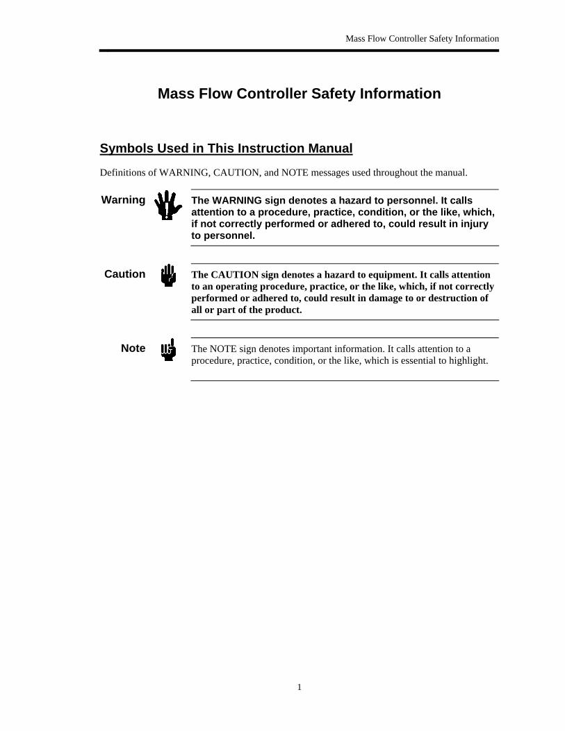
Definitions of WARNING, CAUTION, and NOTE messages used throughout the manual.
Warning
The WARNING sign denotes a hazard to personnel. It calls attention to a procedure, practice, condition, or the like, which, if not correctly performed or adhered to, could result in injury to personnel.
Caution
The CAUTION sign denotes a hazard to equipment. It calls attention to an operating procedure, practice, or the like, which, if not correctly performed or adhered to, could result in damage to or destruction of all or part of the product.
Note
The NOTE sign denotes important information. It calls attention to a procedure, practice, condition, or the like, which is essential to highlight.
Symbols Found on the Unit
2
Symbols Found on the Unit
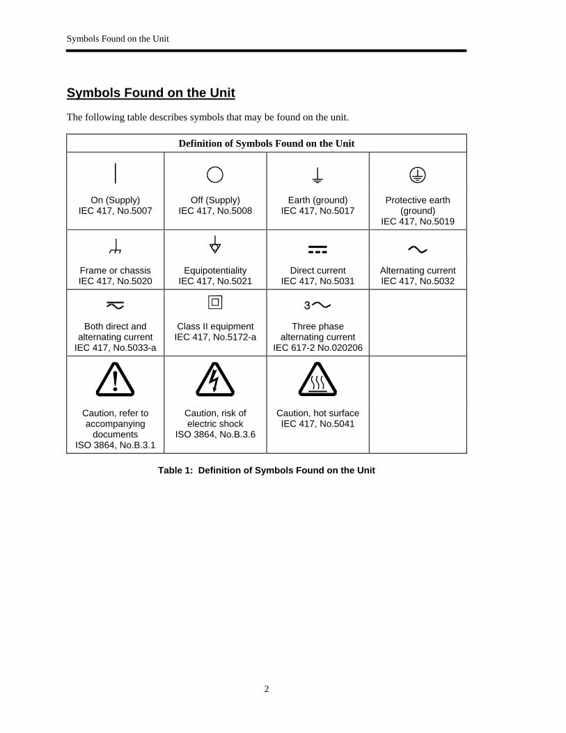
The following table describes symbols that may be found on the unit.
Definition of Symbols Found on the Unit
|
On (Supply) IEC 417, No.5007
Off (Supply) IEC 417, No.5008
Earth (ground) IEC 417, No.5017
Protective earth (ground)
IEC 417, No.5019
Frame or chassis IEC 417, No.5020
Equipotentiality IEC 417, No.5021
Direct current IEC 417, No.5031
Alternating current IEC 417, No.5032
Both direct and alternating current
IEC 417, No.5033-a
Class II equipment IEC 417, No.5172-a
Three phase alternating current
IEC 617-2 No.020206
Caution, refer to accompanying
documents ISO 3864, No.B.3.1
Caution, risk of electric shock
ISO 3864, No.B.3.6
Caution, hot surface IEC 417, No.5041
Table 1: Definition of Symbols Found on the Unit
Mass Flow Controller Safety Information
3
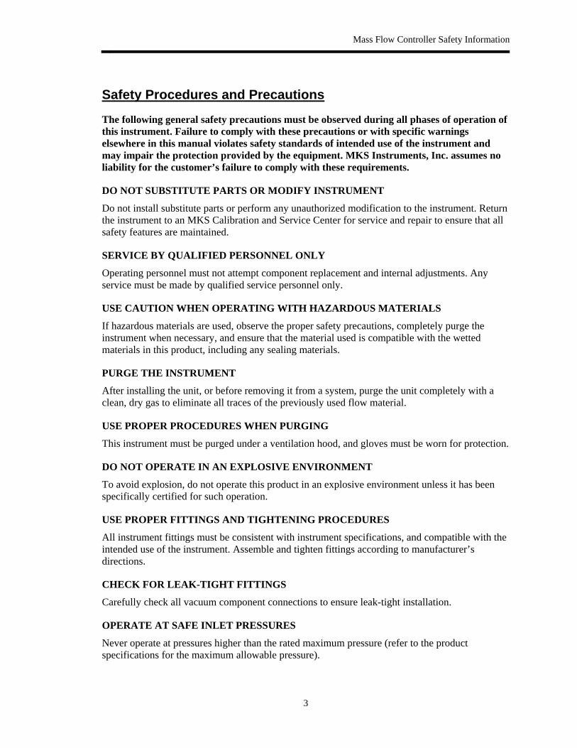
Safety Procedures and Precautions
The following general safety precautions must be observed during all phases of operation of this instrument. Failure to comply with these precautions or with specific warnings elsewhere in this manual violates safety standards of intended use of the instrument and may impair the protection provided by the equipment. MKS Instruments, Inc. assumes no liability for the customer’s failure to comply with these requirements.
DO NOT SUBSTITUTE PARTS OR MODIFY INSTRUMENT
Do not install substitute parts or perform any unauthorized modification to the instrument. Return the instrument to an MKS Calibration and Service Center for service and repair to ensure that all safety features are maintained.
SERVICE BY QUALIFIED PERSONNEL ONLY
Operating personnel must not attempt component replacement and internal adjustments. Any service must be made by qualified service personnel only.
USE CAUTION WHEN OPERATING WITH HAZARDOUS MATERIALS
If hazardous materials are used, observe the proper safety precautions, completely purge the instrument when necessary, and ensure that the material used is compatible with the wetted materials in this product, including any sealing materials.
PURGE THE INSTRUMENT
After installing the unit, or before removing it from a system, purge the unit completely with a clean, dry gas to eliminate all traces of the previously used flow material.
USE PROPER PROCEDURES WHEN PURGING
This instrument must be purged under a ventilation hood, and gloves must be worn for protection.
DO NOT OPERATE IN AN EXPLOSIVE ENVIRONMENT
To avoid explosion, do not operate this product in an explosive environment unless it has been specifically certified for such operation.
USE PROPER FITTINGS AND TIGHTENING PROCEDURES
All instrument fittings must be consistent with instrument specifications, and compatible with the intended use of the instrument. Assemble and tighten fittings according to manufacturer’s directions.
CHECK FOR LEAK-TIGHT FITTINGS
Carefully check all vacuum component connections to ensure leak-tight installation.
OPERATE AT SAFE INLET PRESSURES
Never operate at pressures higher than the rated maximum pressure (refer to the product specifications for the maximum allowable pressure).

Safety Procedures and Precautions
4
INSTALL A SUITABLE BURST DISC
When operating from a pressurized gas source, install a suitable burst disc in the vacuum system to prevent system explosion should the system pressure rise.
KEEP THE UNIT FREE OF CONTAMINANTS
Do not allow contaminants to enter the unit before or during use. Contamination such as dust, dirt, lint, glass chips, and metal chips may permanently damage the unit or contaminate the process.
ALLOW THE UNIT TO WARM UP
If the unit is used to control dangerous gases, they should not be applied before the unit has completely warmed up. Use a positive shutoff valve to ensure that no erroneous flow can occur during warm up.

Sicherheitshinweise für den Massenflußregler
5
Sicherheitshinweise für den Massenflußregler
In dieser Betriebsanleitung vorkommende Symbole
Bedeutung der mit WARNUNG!, VORSICHT! und HINWEIS gekennzeichneten Absätze in dieser Betriebsanleitung.
Warnung!
Das Symbol WARNUNG! weist auf eine Gefahr für das Bedienpersonal hin. Es macht auf einen Arbeitsablauf, eine Arbeitsweise, einen Zustand oder eine sonstige Gegebenheit aufmerksam, deren unsachgemäße Ausführung bzw. ungenügende Berücksichtigung zu Verletzungen führen kann.
Vorsicht!
Das Symbol VORSICHT! weist auf eine Gefahr für das Gerät hin. Es macht auf einen Bedienungsablauf, eine Arbeitsweise oder eine sonstige Gegebenheit aufmerksam, deren unsachgemäße Ausführung bzw. ungenügende Berücksichtigung zu einer Beschädigung oder Zerstörung des Gerätes oder von Teilen des Gerätes führen kann.
Hinweis
Das Symbol HINWEIS macht auf wichtige Informationen bezüglich eines Arbeitsablaufs, einer Arbeitsweise, eines Zustands oder einer sonstige Gegebenheit aufmerksam.
Erklärung der am Gerät angebrachten Symbole
6
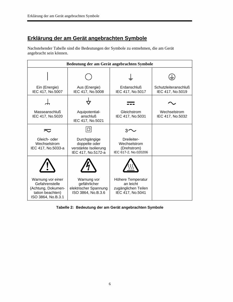
Erklärung der am Gerät angebrachten Symbole
Nachstehender Tabelle sind die Bedeutungen der Symbole zu entnehmen, die am Gerät angebracht sein können.
Bedeutung der am Gerät angebrachten Symbole
|
Ein (Energie) IEC 417, No.5007
Aus (Energie) IEC 417, No.5008
Erdanschluß IEC 417, No.5017
SchutzleiteranschlußIEC 417, No.5019
Masseanschluß IEC 417, No.5020
Aquipotential-anschluß
IEC 417, No.5021
Gleichstrom IEC 417, No.5031
Wechselstrom IEC 417, No.5032
Gleich- oder Wechselstrom
IEC 417, No.5033-a
Durchgängige doppelte oder
verstärkte Isolierung IEC 417, No.5172-a
Dreileiter-Wechselstrom (Drehstrom)
IEC 617-2, No.020206
Warnung vor einer Gefahrenstelle
(Achtung, Dokumen-tation beachten)
ISO 3864, No.B.3.1
Warnung vor gefährlicher
elektrischer SpannungISO 3864, No.B.3.6
Höhere Temperatur an leicht
zugänglichen Teilen IEC 417, No.5041
Tabelle 2: Bedeutung der am Gerät angebrachten Symbole

Sicherheitshinweise für den Massenflußregler
7
Sicherheitsvorschriften und Vorsichtsmaßnahmen
Folgende allgemeine Sicherheitsvorschriften sind während allen Betriebsphasen dieses Gerätes zu befolgen. Eine Mißachtung der Sicherheitsvorschriften und sonstiger Warnhinweise in dieser Betriebsanleitung verletzt die für dieses Gerät und seine Bedienung geltenden Sicherheitsstandards, und kann die Schutzvorrichtungen an diesem Gerät wirkungslos machen. MKS Instruments, Inc. haftet nicht für Mißachtung dieser Sicherheitsvorschriften seitens des Kunden.
Niemals Teile austauschen oder Änderungen am Gerät vornehmen!
Ersetzen Sie keine Teile mit baugleichen oder ähnlichen Teilen, und nehmen Sie keine eigenmächtigen Änderungen am Gerät vor. Schicken Sie das Gerät zwecks Wartung und Reparatur an den MKS-Kalibrierungs- und -Kundendienst ein. Nur so wird sichergestellt, daß alle Schutzvorrichtungen voll funktionsfähig bleiben.
Wartung nur durch qualifizierte Fachleute!
Das Auswechseln von Komponenten und das Vornehmen von internen Einstellungen darf nur von qualifizierten Fachleuten durchgeführt werden, niemals vom Bedienpersonal.
Vorsicht beim Arbeiten mit gefährlichen Stoffen!
Wenn gefährliche Stoffe verwendet werden, muß der Bediener die entsprechenden Sicherheitsvorschriften genauestens einhalten, das Gerät, falls erforderlich, vollständig spülen, sowie sicherstellen, daß der Gefahrstoff die von ihm benetzten, am Gerät verwendeten Materialien, insbesondere Dichtungen, nicht angreift.
Spülen des Gerätes mit Gas!
Nach dem Installieren oder vor dem Ausbau aus einem System muß das Gerät unter Einsatz eines reinen Trockengases vollständig gespült werden, um alle Rückstände des Vorgängermediums zu entfernen.
Anweisungen zum Spülen des Gerätes
Das Gerät darf nur unter einer Ablufthaube gespült werden. Schutzhandschuhe sind zu tragen.
Gerät nicht zusammen mit explosiven Stoffen, Gasen oder Dämpfen benutzen!
Um der Gefahr einer Explosion vorzubeugen, darf dieses Gerät niemals zusammen mit (oder in der Nähe von) explosiven Stoffen aller Art eingesetzt werden, sofern es nicht ausdrücklich für diesen Zweck zugelassen ist.
Anweisungen zum Installieren der Armaturen!
Alle Anschlußstücke und Armaturenteile müssen mit der Gerätespezifikation übereinstimmen, und mit dem geplanten Einsatz des Gerätes kompatibel sein. Der Einbau, insbesondere das Anziehen und Abdichten, muß gemäß den Anweisungen des Herstellers vorgenommen werden.
Verbindungen auf Undichtigkeiten prüfen!
Überprüfen Sie sorgfältig alle Verbindungen der Vakuumkomponenten auf undichte Stellen.

Sicherheitsvorschriften und Vorsichtsmaßnahmen
8
Gerät nur unter zulässigen Anschlußdrücken betreiben!
Betreiben Sie das Gerät niemals unter Drücken, die den maximal zulässigen Druck (siehe Produktspezifikationen) übersteigen.
Geeignete Berstscheibe installieren!
Wenn mit einer unter Druck stehenden Gasquelle gearbeitet wird, sollte eine geeignete Berstscheibe in das Vakuumsystem installiert werden, um eine Explosionsgefahr aufgrund von steigendem Systemdruck zu vermeiden.
Verunreinigungen im Gerät vermeiden!
Stellen Sie sicher, daß Verunreinigungen jeglicher Art weder vor dem Einsatz noch während des Betriebs in das Instrumenteninnere gelangen können. Staub- und Schmutzpartikel, Glassplitter oder Metallspäne können das Gerät dauerhaft beschädigen oder Prozeß und Meßwerte verfälschen.
Geräteeinheit auf Arbeitstemperatur bringen!
Wird das Gerät zur Flußregelung gefährlicher Gase verwendet, so dürfen diese nur nach Abschluß des Anwärmvorgangs zugeführt werden. Um das versehentliche Fließen von Gas während der Aufheizperiode zu verhindern, sollte ein Absperrventil (normal geschlossen) eingebaut werden.
Informations relatives à la sécurité pour le contrôleur de débit de masse
9
Informations relatives à la sécurité pour le contrôleur de débit de masse
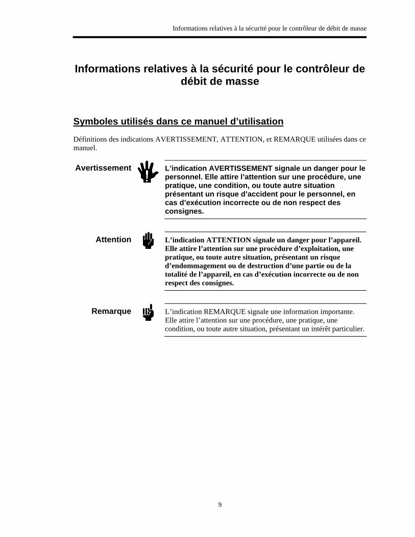
Symboles utilisés dans ce manuel d’utilisation
Définitions des indications AVERTISSEMENT, ATTENTION, et REMARQUE utilisées dans ce manuel.
Avertissement
L’indication AVERTISSEMENT signale un danger pour lepersonnel. Elle attire l’attention sur une procédure, une pratique, une condition, ou toute autre situation présentant un risque d’accident pour le personnel, en cas d’exécution incorrecte ou de non respect des consignes.
Attention
L’indication ATTENTION signale un danger pour l’appareil. Elle attire l’attention sur une procédure d’exploitation, une pratique, ou toute autre situation, présentant un risque d’endommagement ou de destruction d’une partie ou de la totalité de l’appareil, en cas d’exécution incorrecte ou de non respect des consignes.
Remarque
L’indication REMARQUE signale une information importante. Elle attire l’attention sur une procédure, une pratique, une condition, ou toute autre situation, présentant un intérêt particulier.
Symboles apparaissant sur l’unité
10
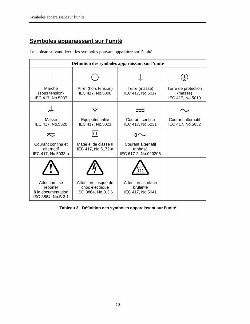
Symboles apparaissant sur l’unité
Le tableau suivant décrit les symboles pouvant apparaître sur l’unité.
Définition des symboles apparaissant sur l’unité
|
Marche (sous tension)
IEC 417, No.5007
Arrêt (hors tension) IEC 417, No.5008
Terre (masse) IEC 417, No.5017
Terre de protection (masse)
IEC 417, No.5019
Masse IEC 417, No.5020
Equipotentialité IEC 417, No.5021
Courant continu IEC 417, No.5031
Courant alternatif IEC 417, No.5032
Courant continu et alternatif
IEC 417, No.5033-a
Matériel de classe II IEC 417, No.5172-a
Courant alternatif triphasé
IEC 617-2, No.020206
Attention : se reporter
à la documentation ISO 3864, No.B.3.1
Attention : risque de choc électrique
ISO 3864, No.B.3.6
Attention : surface brûlante
IEC 417, No.5041
Tableau 3: Définition des symboles apparaissant sur l’unité

Informations relatives à la sécurité pour le contrôleur de débit de masse
11
Mesures de sécurité et précautions
Prendre les précautions générales de sécurité suivantes pendant toutes les phases d’exploitation de cet appareil. Le non respect des ces précautions ou des avertissements contenus dans ce manuel constitue une violation des normes de sécurité relatives à l’utilisation de l’appareil et peut diminuer la protection fournie par l’appareil. MKS Instruments, Inc. n’assume aucune responsabilité concernant le non respect des consignes par les clients.
PAS DE SUBSTITUTION DE PIÈCES OU DE MODIFICATION DE L’APPAREIL
Ne pas installer des pièces de substitution ou effectuer des modifications non autorisées sur l’appareil. Renvoyer l’appareil à un centre de service et de calibrage MKS pour tout dépannage ou réparation afin de garantir l’intégrité des dispositifs de sécurité.
DÉPANNAGE UNIQUEMENT PAR DU PERSONNEL QUALIFIÉ
Le personnel d’exploitation ne doit pas essayer de remplacer des composants ou de faire des réglages internes. Tout dépannage doit être uniquement effectué par du personnel qualifié.
PRÉCAUTION EN CAS D’UTILISATION AVEC DES PRODUITS DANGEREUX
Si des produits dangereux sont utilisés, prendre les mesures de précaution appropriées, purger complètement l’appareil quand cela est nécessaire, et s’assurer que les produits utilisés sont compatibles avec les composants liquides de l’appareil, y compris les matériaux d’étanchéité.
PURGE DE L’APPAREIL
Après l’installation de l’unité, ou avant son enlèvement d’un système, purger l’unité complètement avec un gaz propre et sec afin d’éliminer toute trace du produit de flux utilisé précédemment.
UTILISATION DES PROCÉDURES APPROPRIÉES POUR LA PURGE
Cet appareil doit être purgé sous une hotte de ventilation, et il faut porter des gants de protection.
PAS D’EXPLOITATION DANS UN ENVIRONNEMENT EXPLOSIF
Pour éviter toute explosion, ne pas utiliser cet appareil dans un environnement explosif, sauf en cas d’homologation spécifique pour une telle exploitation.
UTILISATION D’ÉQUIPEMENTS APPROPRIÉS ET PROCÉDURES DE SERRAGE
Tous les équipements de l’appareil doivent être cohérents avec ses spécifications, et compatibles avec l’utilisation prévue de l’appareil. Assembler et serrer les équipements conformément aux directives du fabricant.
VÉRIFICATION DE L’ÉTANCHÉITÉ DES CONNEXIONS
Vérifier attentivement toutes les connexions des composants pour le vide afin de garantir l’étanchéité de l’installation.
Mesures de sécurité et précautions
12
EXPLOITATION AVEC DES PRESSIONS D’ENTRÉE NON DANGEREUSES
Ne jamais utiliser des pressions supérieures à la pression nominale maximum (se reporter aux spécifications de l’unité pour la pression maximum admissible).
INSTALLATION D’UN DISQUE D’ÉCHAPPEMENT ADAPTÉ
En cas d’exploitation avec une source de gaz pressurisé, installer un disque d’échappement adapté dans le système à vide afin d’éviter une explosion du système en cas d’augmentation de la pression.
MAINTIEN DE L’UNITÉ À L’ABRI DES CONTAMINATIONS
Ne pas laisser des produits contaminants pénétrer dans l’unité avant ou pendant l’utilisation. Des produits contaminants tels que des poussières et des fragments de tissu, de glace et de métal peuvent endommager l’unité d’une manière permanente ou contaminer le processus.
RESPECT DU TEMPS D’ÉCHAUFFEMENT
Si l’unité est utilisée pour contrôler des gaz dangereux, ceux-ci ne doivent pas être appliqués avant l’échauffement complet de l’unité. Utiliser une valve de fermeture positive afin de garantir qu’aucun flux ne se produise par erreur pendant l’échauffement.
Medidas de seguridad del controlador de flujo de masa
13
Medidas de seguridad del controlador de flujo de masa
Símbolos usados en este manual de instrucciones
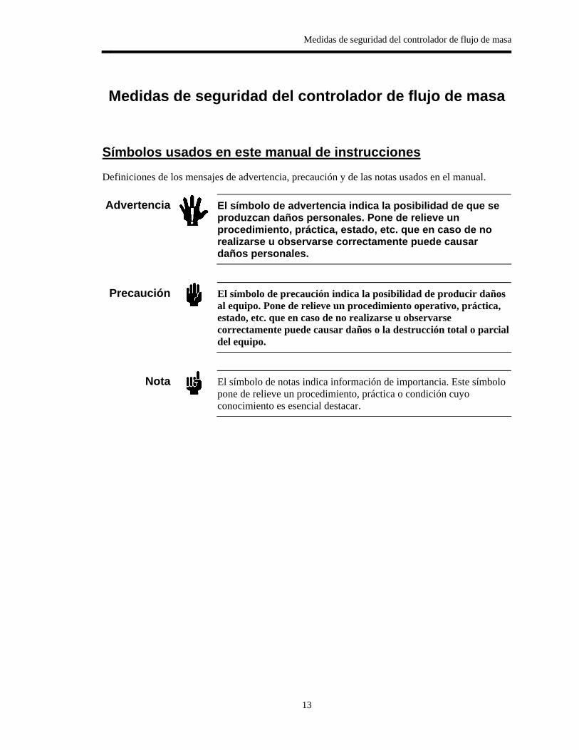
Definiciones de los mensajes de advertencia, precaución y de las notas usados en el manual.
Advertencia
El símbolo de advertencia indica la posibilidad de que se produzcan daños personales. Pone de relieve un procedimiento, práctica, estado, etc. que en caso de no realizarse u observarse correctamente puede causar daños personales.
Precaución
El símbolo de precaución indica la posibilidad de producir daños al equipo. Pone de relieve un procedimiento operativo, práctica, estado, etc. que en caso de no realizarse u observarse correctamente puede causar daños o la destrucción total o parcial del equipo.
Nota
El símbolo de notas indica información de importancia. Este símbolo pone de relieve un procedimiento, práctica o condición cuyo conocimiento es esencial destacar.

Símbolos hallados en la unidad
14
Símbolos hallados en la unidad
La tabla siguiente contiene los símbolos que puede hallar en la unidad.
Definición de los símbolos hallados en la unidad
|
Encendido (alimentación eléctrica)
IEC 417, N° 5007
Apagado (alimentación eléctrica)
IEC 417, N° 5008
Puesta a tierra IEC 417, N° 5017
Protección a tierra IEC 417, N° 5019
Caja o chasis IEC 417, N° 5020
Equipotencialidad IEC 417, N° 5021
Corriente continua IEC 417, N° 5031
Corriente alterna IEC 417, N° 5032
Corriente continua y alterna
IEC 417, N° 5033-a
Equipo de clase II IEC 417, N° 5172-a
Corriente alterna trifásica
IEC 617-2, N° 020206
Precaución. Consulte
los documentos adjuntos
ISO 3864, N° B.3.1
Precaución. Riesgo de descarga eléctricaISO 3864, N° B.3.6
Precaución. Superficie caliente
IEC 417, N° 5041
Tabla 4: Definición de los símbolos hallados en la unidad
Medidas de seguridad del controlador de flujo de masa
15
Procedimientos y precauciones de seguridad
Las precauciones generales de seguridad descritas a continuación deben observarse durante todas las etapas de funcionamiento del instrumento. La falta de cumplimiento de dichas precauciones o de las advertencias específicas a las que se hace referencia en el manual, constituye una violación de las normas de seguridad establecidas para el uso previsto del instrumento y podría anular la protección proporcionada por el equipo. Si el cliente no cumple dichas precauciones y advertencias, MKS Instruments, Inc. no asume responsabilidad legal alguna.
NO UTILICE PIEZAS NO ORIGINALES O MODIFIQUE EL INSTRUMENTO
No instale piezas que no sean originales o modifique el instrumento sin autorización. Para asegurar el correcto funcionamiento de todos los dispositivos de seguridad, envíe el instrumento al Centro de servicio y calibración de MKS toda vez que sea necesario repararlo o efectuar tareas de mantenimiento.
LAS REPARACIONES DEBEN SER EFECTUADAS ÚNICAMENTE POR TÉCNICOS AUTORIZADOS
Los operarios no deben intentar reemplazar los componentes o realizar tareas de ajuste en el interior del instrumento. Las tareas de mantenimiento o reparación deben ser realizadas únicamente por personal autorizado.
TENGA CUIDADO CUANDO TRABAJE CON MATERIALES TÓXICOS
Cuando se utilicen materiales tóxicos, es responsabilidad de los operarios cumplir las medidas de seguridad correspondientes, purgar totalmente el instrumento cuando sea necesario y comprobar que el material utilizado sea compatible con los materiales humedecidos de este producto e inclusive, con los materiales de sellado.
PURGUE EL INSTRUMENTO
Una vez instalada la unidad o antes de retirarla del sistema, purgue completamente la unidad con gas limpio y seco para eliminar todo resto de la sustancia líquida empleada anteriormente.
USE PROCEDIMIENTOS ADECUADOS PARA REALIZAR LA PURGA
El instrumento debe purgarse debajo de una campana de ventilación y deben utilizarse guantes protectores.
NO HAGA FUNCIONAR ESTE INSTRUMENTO EN UN AMBIENTE CON RIESGO DE EXPLOSIONES
Para evitar que se produzcan explosiones, no haga funcionar este producto en un ambiente con riesgo de explosiones, excepto cuando el mismo haya sido certificado específicamente para tal uso.
Procedimientos y precauciones de seguridad
16
USE ACCESORIOS ADECUADOS Y REALICE CORRECTAMENTE LOS PROCEDIMIENTOS DE AJUSTE
Todos los accesorios del instrumento deben cumplir las especificaciones del mismo y ser compatibles con el uso que se debe dar al instrumento. Arme y ajuste los accesorios de acuerdo con las instrucciones del fabricante.
COMPRUEBE QUE LAS CONEXIONES SEAN A PRUEBA DE FUGAS
Inspeccione cuidadosamente las conexiones de los componentes de vacío para comprobar que hayan sido instalados a prueba de fugas.
HAGA FUNCIONAR EL INSTRUMENTO CON PRESIONES DE ENTRADA SEGURAS
No haga funcionar nunca el instrumento con presiones superiores a la máxima presión nominal (en las especificaciones del instrumento hallará la presión máxima permitida).
INSTALE UNA CÁPSULA DE SEGURIDAD ADECUADA
Cuando el instrumento funcione con una fuente de gas presurizado, instale una cápsula de seguridad adecuada en el sistema de vacío para evitar que se produzcan explosiones cuando suba la presión del sistema.
MANTENGA LA UNIDAD LIBRE DE CONTAMINANTES
No permita el ingreso de contaminantes en la unidad antes o durante su uso. Los productos contaminantes tales como polvo, suciedad, pelusa, lascas de vidrio o virutas de metal pueden dañar irreparablemente la unidad o contaminar el proceso.
PERMITA QUE LA UNIDAD SE CALIENTE
Si se utiliza la unidad para controlar gases peligrosos, no libere los gases hasta que la unidad termine de calentarse. Use una válvula de cierre positivo para impedir todo flujo no deseado durante el período de calentamiento.
Chapter One: General Information
17
Chapter One: General Information
Product Description
The MKS Plasma Process Training System is a complete table-top sputtering system that includes:
• 300 watt 13.56 MHz generator • Manual “L” matching network • High vacuum pumping system • MKS Type 146 ClusterGauge™ Measurement and Control System • Type 626B 1 Torr FS Baratron capacitance manometer • Convection Pirani gauge • One Type M100B mass flow controller, 50 sccm (nitrogen) • 6-inch process chamber with substrate holder • 4-inch diameter magnetron sputter cathode with copper target
Optional accessories include:
• HPS IMAG cold cathode ion gauge and controller for base pressure measurement • ENI V/I Probe® RF impedance analyzer • Other target materials (e.g., SiO2, Aluminum, etc.) • Second MFC for reactive sputtering (e.g., nitride films)
How This Manual is Organized
The MKS Plasma Process Training System is supplied as a kit of components. This manual provides instructions on how to set up, install, and operate the PPTS-1A unit.
Before assembling and using your Plasma Process Training System please carefully read and familiarize yourself with the manual and the precautionary notes.
Chapter One, General Information, (this chapter) introduces the product and describes the organization of the manual.
Chapter Two, Software, describes the MKS146 software associated with the 146 instrument.
Chapter Three, PPTS-1A Operation, details operation of the vacuum system components, electronic instruments, and magnetron sputter cathode.
Customer Support
18
Customer Support
Standard maintenance and repair services are available at all of our regional MKS Calibration and Service Centers, listed on the back cover. If any difficulties arise in the use of your Plasma Process Training System, contact any authorized MKS Calibration and Service Center. If it is necessary to return any MKS component to MKS, please obtain an RMA (Return Material Authorization) number from the MKS Calibration and Service Center before shipping. The RMA number expedites handling and ensures proper servicing of your instrument.
Warning
All returns to MKS Instruments must be free of harmful, corrosive, radioactive, and toxic materials.
Questions or comments regarding this manual can be addressed to the MKS Training Department at the address indicated on the cover of this manual.
Chapter Two: Software
19
Chapter Two: Software
Setup and Operation Using the Windows Software
The 146 ClusterGauge may be controlled from the instrument’s keypad or by means of the included Windows software. The Windows MKS146 software makes setting up and running the PPTS very simple. This section will cover the use of this software.
Please note that the software is not capable of operating both MFCs in ratio mode. Also, if the computer is assigned to other tasks (e.g., operating a V/I Probe) and a second RS232 port is not available for the 146 control software, the operator of the PPTS will have to use the 146C’s keypad for setting changes.
In these situations it is recommended that the 146 software be used to perform the basic setup functions and then use the front panel for items specific to the process recipe. These items would include recipes (setpoint, gain and lead parameters, and gas ratio).
Windows MKS146
Program Installation and Setup Overview The software is contained in two zip files (Disk 1 and Disk 2). Unzip these into a common folder and click on the setup program SETUP.EXE. The program will install as:
C:\Program Files\MKS146
Before the program can be run, the 146 instrument must be connected to the PC via a “straight-through” RS-232 cable. Upon opening the program, a splash screen appears. Clicking on the splash screen will open the main screen. If the communication parameters are not correct, a dialog box will appear. The communications parameters are 9600 baud, even parity, 7 data bits, and 1 stop bit. Also, select the proper communications port.
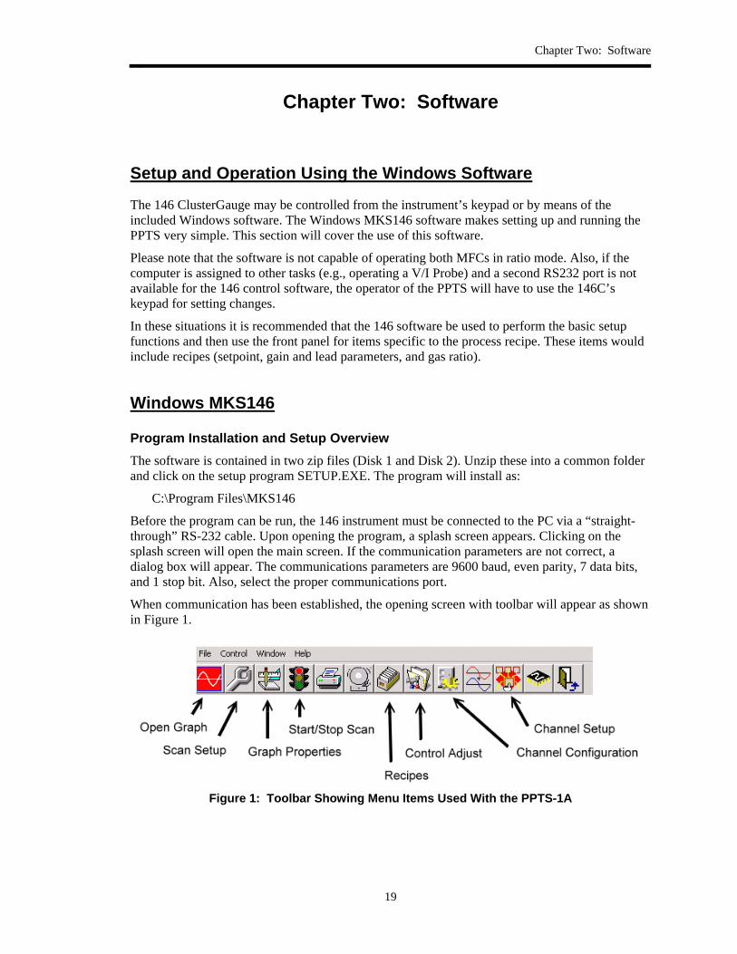
When communication has been established, the opening screen with toolbar will appear as shown in Figure 1.
Figure 1: Toolbar Showing Menu Items Used With the PPTS-1A
Windows MKS146
20
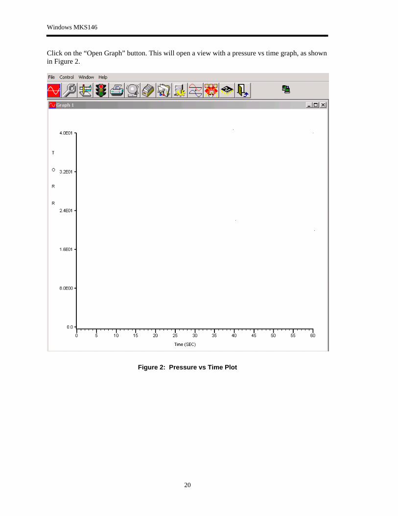
Click on the “Open Graph” button. This will open a view with a pressure vs time graph, as shown in Figure 2.
Figure 2: Pressure vs Time Plot
Chapter Two: Software
21
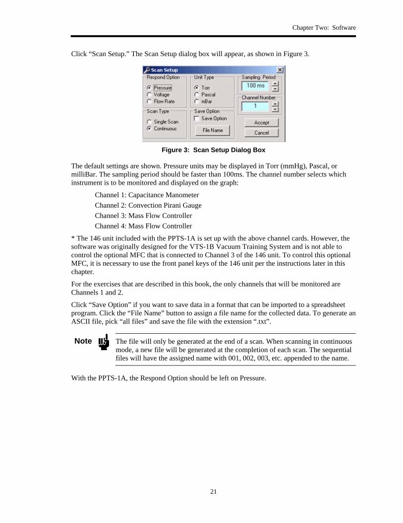
Click “Scan Setup.” The Scan Setup dialog box will appear, as shown in Figure 3.
Figure 3: Scan Setup Dialog Box
The default settings are shown. Pressure units may be displayed in Torr (mmHg), Pascal, or milliBar. The sampling period should be faster than 100ms. The channel number selects which instrument is to be monitored and displayed on the graph:
Channel 1: Capacitance Manometer Channel 2: Convection Pirani Gauge Channel 3: Mass Flow Controller Channel 4: Mass Flow Controller
* The 146 unit included with the PPTS-1A is set up with the above channel cards. However, the software was originally designed for the VTS-1B Vacuum Training System and is not able to control the optional MFC that is connected to Channel 3 of the 146 unit. To control this optional MFC, it is necessary to use the front panel keys of the 146 unit per the instructions later in this chapter.
For the exercises that are described in this book, the only channels that will be monitored are Channels 1 and 2.
Click “Save Option” if you want to save data in a format that can be imported to a spreadsheet program. Click the “File Name” button to assign a file name for the collected data. To generate an ASCII file, pick “all files” and save the file with the extension “.txt”.
Note
The file will only be generated at the end of a scan. When scanning in continuous mode, a new file will be generated at the completion of each scan. The sequential files will have the assigned name with 001, 002, 003, etc. appended to the name.
With the PPTS-1A, the Respond Option should be left on Pressure.
Windows MKS146
22
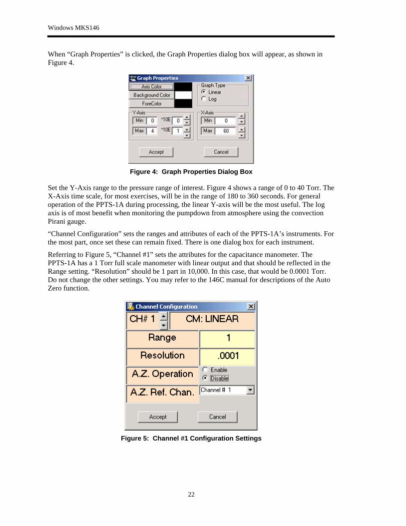
When “Graph Properties” is clicked, the Graph Properties dialog box will appear, as shown in Figure 4.
Figure 4: Graph Properties Dialog Box
Set the Y-Axis range to the pressure range of interest. Figure 4 shows a range of 0 to 40 Torr. The X-Axis time scale, for most exercises, will be in the range of 180 to 360 seconds. For general operation of the PPTS-1A during processing, the linear Y-axis will be the most useful. The log axis is of most benefit when monitoring the pumpdown from atmosphere using the convection Pirani gauge.
“Channel Configuration” sets the ranges and attributes of each of the PPTS-1A’s instruments. For the most part, once set these can remain fixed. There is one dialog box for each instrument.
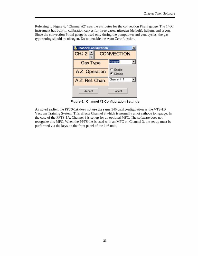
Referring to Figure 5, “Channel #1” sets the attributes for the capacitance manometer. The PPTS-1A has a 1 Torr full scale manometer with linear output and that should be reflected in the Range setting. “Resolution” should be 1 part in 10,000. In this case, that would be 0.0001 Torr. Do not change the other settings. You may refer to the 146C manual for descriptions of the Auto Zero function.
Figure 5: Channel #1 Configuration Settings
Chapter Two: Software
23
Referring to Figure 6, “Channel #2” sets the attributes for the convection Pirani gauge. The 146C instrument has built-in calibration curves for three gases: nitrogen (default), helium, and argon. Since the convection Pirani gauge is used only during the pumpdown and vent cycles, the gas type setting should be nitrogen. Do not enable the Auto Zero function.
Figure 6: Channel #2 Configuration Settings
As noted earlier, the PPTS-1A does not use the same 146 card configuration as the VTS-1B Vacuum Training System. This affects Channel 3 which is normally a hot cathode ion gauge. In the case of the PPTS-1A, Channel 3 is set up for an optional MFC. The software does not recognize this MFC. When the PPTS-1A is used with an MFC on Channel 3, the set up must be performed via the keys on the front panel of the 146 unit.
Windows MKS146
24
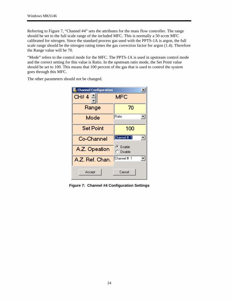
Referring to Figure 7, “Channel #4” sets the attributes for the mass flow controller. The range should be set to the full scale range of the included MFC. This is normally a 50 sccm MFC calibrated for nitrogen. Since the standard process gas used with the PPTS-1A is argon, the full scale range should be the nitrogen rating times the gas correction factor for argon (1.4). Therefore the Range value will be 70.
“Mode” refers to the control mode for the MFC. The PPTS-1A is used in upstream control mode and the correct setting for this value is Ratio. In the upstream ratio mode, the Set Point value should be set to 100. This means that 100 percent of the gas that is used to control the system goes through this MFC.
The other parameters should not be changed.
Figure 7: Channel #4 Configuration Settings
Chapter Two: Software
25
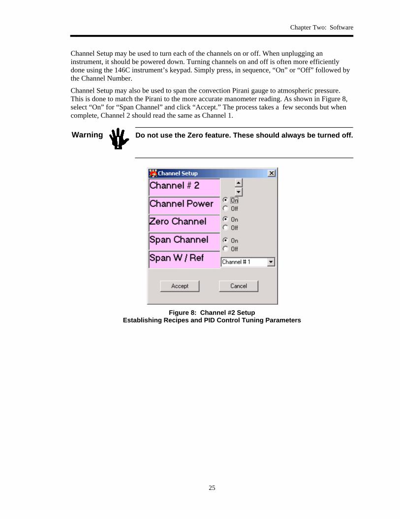
Channel Setup may be used to turn each of the channels on or off. When unplugging an instrument, it should be powered down. Turning channels on and off is often more efficiently done using the 146C instrument’s keypad. Simply press, in sequence, “On” or “Off” followed by the Channel Number.
Channel Setup may also be used to span the convection Pirani gauge to atmospheric pressure. This is done to match the Pirani to the more accurate manometer reading. As shown in Figure 8, select “On” for “Span Channel” and click “Accept.” The process takes a few seconds but when complete, Channel 2 should read the same as Channel 1.
Warning
Do not use the Zero feature. These should always be turned off.
Figure 8: Channel #2 Setup
Establishing Recipes and PID Control Tuning Parameters
Windows MKS146
26
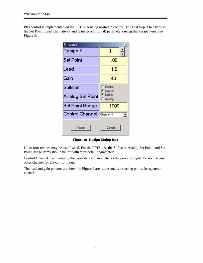
PID control is implemented on the PPTS-1A using upstream control. The first step is to establish the Set Point, Lead (derivative), and Gain (proportional) parameters using the Recipe item. See Figure 9.
Figure 9: Recipe Dialog Box
Up to four recipes may be established. For the PPTS-1A, the Softstart, Analog Set Point, and Set Point Range items should be left with their default parameters.
Control Channel 1 will employ the capacitance manometer as the pressure input. Do not use any other channel for the control input.
The lead and gain parameters shown in Figure 9 are representative starting points for upstream control.
Chapter Two: Software
27
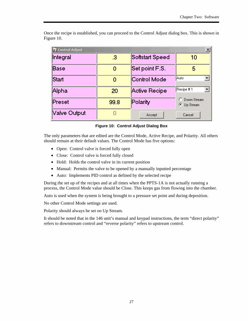
Once the recipe is established, you can proceed to the Control Adjust dialog box. This is shown in Figure 10.
Figure 10: Control Adjust Dialog Box
The only parameters that are edited are the Control Mode, Active Recipe, and Polarity. All others should remain at their default values. The Control Mode has five options:
• Open: Control valve is forced fully open • Close: Control valve is forced fully closed • Hold: Holds the control valve in its current position • Manual: Permits the valve to be opened by a manually inputted percentage • Auto: Implements PID control as defined by the selected recipe
During the set up of the recipes and at all times when the PPTS-1A is not actually running a process, the Control Mode value should be Close. This keeps gas from flowing into the chamber.
Auto is used when the system is being brought to a pressure set point and during deposition.
No other Control Mode settings are used.
Polarity should always be set on Up Stream.
It should be noted that in the 146 unit’s manual and keypad instructions, the term “direct polarity” refers to downstream control and “reverse polarity” refers to upstream control.

Operation from the 146C Front Panel
28
Operation from the 146C Front Panel
This section includes all of the steps required to use the PPTS by controlling the 146C from its front panel keypad. It is assumed that the configuration has one capacitance manometer card, one Pirani card, and two MFC cards. There will also be a control (M) card in the channel 5 slot. Attached instruments include one 1.0 Torr manometer and two 50 sccm (nitrogen) MFCs. It is assumed that the channel 4 MFC will be used with argon (gas correction factor = 1.4) and the channel 3 MFC will be used with nitrogen. The channel 3 MFC will only be used for reactive sputtering, in ratio mode with the argon MFC.
The first step is to set up the manometer and MFC channels. More detail may be found in the 146C ClusterGauge manual.
Channel 1 Setup 1. Put the 146 in SETUP mode by pushing the [DISPLAY MODE] key until you see the
word SETUP appear in the display. 2. Push the up or down arrow key until you see SENSOR CAL on the right side of the
display. The upper left display will be flashing a number. This is the channel number that you will be editing if you press the ENTER key.
3. Set the channel number to 1 by pressing the 1 key and then press the ENTER key. The main display will now be flashing. This is the full scale range.
4. Change the full scale range to 1 (Torr) by pressing the 1 key and then ENTER. Now the upper middle number will be flashing. This is the resolution.
5. Set the resolution to 10-4 Torr (this is 1/10,000 of full scale, the practical resolution limit of the capacitance manometer) by pressing the 4 key and then ENTER. This will return the display to the flashing channel number. Note that the upper right value should read Ln. This indicates that the manometer is has a linear scale.
Channel 4 Setup (Single Gas Sputtering) 1. Set the channel number to 4 by pressing the 4 key followed by ENTER. The main display
will now be flashing. This is the full scale range. 2. Since this MFC will be used with argon (GCF = 1.4), enter the full scale range (50 sccm)
factored by 1.4 or 70. Then press the ENTER key. The upper center value (MFC mode) will be adjusted in the next steps. The upper right value should read FC (Flow Controller).
Channel 3 Setup (reactive Sputtering With Nitrogen Mixed With Argon) You may ignore this step if the PPTS-1A will not be used in reactive sputtering mode.
1. Set the channel number to 3 by pressing the 3 key followed by ENTER. The main display will now be flashing. This is the full scale range.
2. Since this MFC will be used with nitrogen (GCF = 1.0), enter the full scale range 50 sccm. Then press the ENTER key. The upper center value (MFC mode) will be adjusted in the next steps. The upper right value should read FC (Flow Controller).

Chapter Two: Software
29
Setting the Code Functions (Single Gas Sputtering) 1. With the upper left display flashing in Sensor Cal, push the up or down arrow key until
you see Code in the bottom right of the display. Codes that need to be set are Codes 14x (Control Settings) and 17x (MFC Settings). The upper left value will be the code number.
2. To set Code 14x, press 1, 4, 1, and then ENTER. The main display will now be flashing either dir or rev. The former is “direct” which means downstream control. The latter is “reverse” which means upstream control. For the PPTS-1A, pressure is controlled via upstream control.
3. If required, set the mode to rev by pressing the up or down arrow key. Press ENTER. 4. The upper right display will now flash. This is the input that is used for control (i.e., the
manometer on channel 1). If the value is not 1, press 1 and then press ENTER. The upper left value 141 will now be flashing.
5. Enter 142, 143, and 144 to ensure that they also indicate rev in the main display and 1 in the top left display.
6. Now you will set Code 17x. Enter 174 to set Code 17 for the channel 4 MFC. For single gas sputtering, the main display should read 100. (This indicates that 100% of the gas flow is through the channel 4 MFC.) Now the upper right value (MFC operation mode) should be flashing. Values are either Set Point (sp), Ratio (ra) or Totalling (to). Use the up or down arrow to set this to ratio (ra) and then press ENTER.
Setting the Code Functions (Reactive Sputtering With Nitrogen Mixed With Argon) In the case of single gas (non-reactive) sputtering, only the flow through the argon MFC on channel 4 is used to regulate the chamber pressure. For reactive sputtering, two MFCs are used in combination. The total flow of gas is used to regulate the chamber pressure but the mix ratio of the two gases controls the type of film that is deposited. Thus, with a copper target and argon as the single process gas, the deposited film will be pure copper. If nitrogen is mixed with the argon, some of the sputtered atoms will react with the nitrogen to form a copper nitride film.
The 146 unit is designed to be able to control pressure while also controlling the ratio of the gases that enter the chamber through the two MFCs. In ratio mode, the control signal is apportioned between the two MFCs based on their chosen ratio set points.
In the following instructions, assume that the ratio will be 80% argon (channel 4) and 20% nitrogen (channel 3).
Assuming that the Channel 3 and 4 Setup steps have been performed as described above and the Code 14x has been set, the only further adjustment that has to be made is in the Code 17x settings.
1. First set Code 17x for Channel 3. As in item 6 in the previous section, enter 173 to set Code 17 for the channel 3 MFC. Since this is the nitrogen channel, set the value in the main display to 20 and press the ENTER key.
2. If the upper left value is not ra, use the up or down arrow to set and press the ENTER key. The upper left value will now be flashing.
3. Now program Code 17x for Channel 4. Enter 174 to set Code 17 for the Channel 4 MFC. Since this is the argon channel, set the value in the main display to 80 and press the ENTER key.

Operation from the 146C Front Panel
30
Setting the Control Recipe Now that the 146 unit is configured for the instruments that are attached to it and the MFCs are set to operate in upstream control mode in either a single gas or dual gas ratio mode, the next step is to set the pressure control recipes in the TUNING mode. The parameters that we will be setting are Lead, Gain, and Setpoint.
1. Push the [DISPLAY MODE] key until you see the word TUNING appear in the display. You should see Ax and Ey at the top of the display. If you do not see this, push the up or down arrow until this display appears. a. Ax shows the Active recipe. Moving to Auto will result in this recipe being used. b. Ey shows the Editable recipe. Any changes will be saved in Recipe y.
2. Note the keys marked in green: Setpoint, Gain, and Lead. These are shortcuts to these parameters when setting up a recipe.
3. Press the [Setpoint] key and enter a value for the setpoint, for example .05 Torr. Press the ENTER key.
4. Press the [Lead] key and enter a value for the lead. A good starting point is 1. Press the ENTER key.
5. Press the [Gain] key and enter a value for the gain. A good starting point is 50. Press the ENTER key.
At this point the PPTS-1A is ready to run with the inputted set up and control parameters.
Chapter Three: PPTS-1A Operation
31
Chapter Three: PPTS-1A Operation
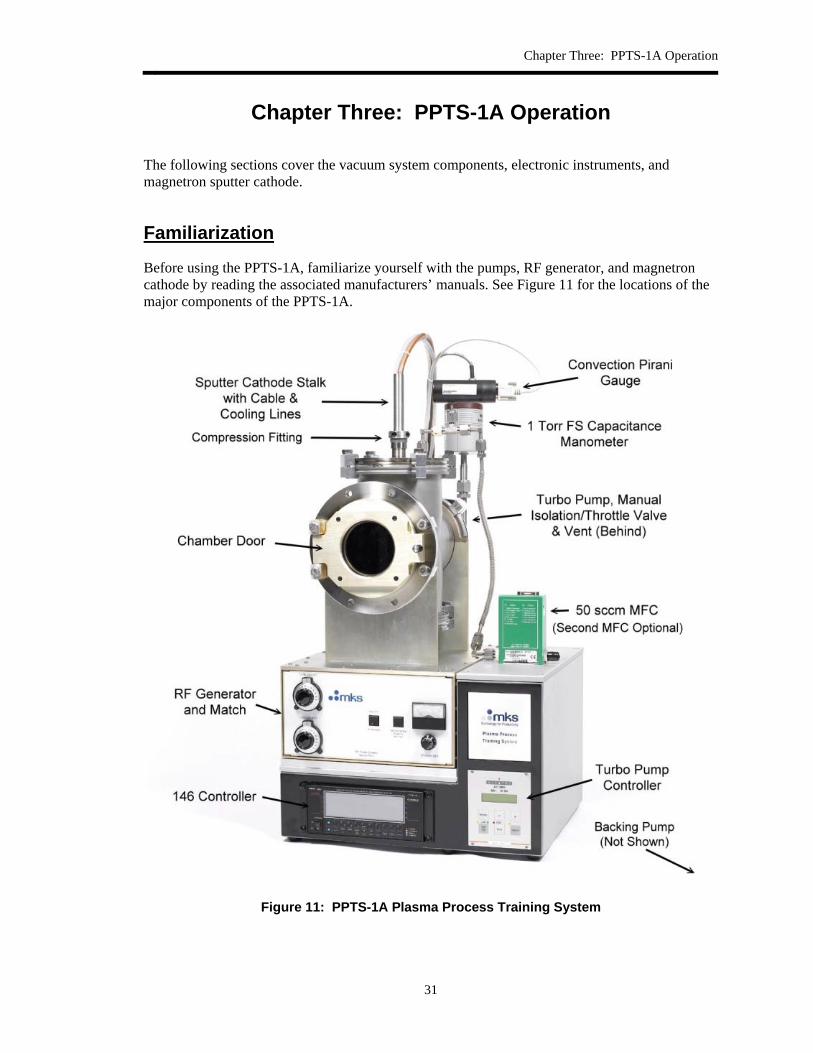
The following sections cover the vacuum system components, electronic instruments, and magnetron sputter cathode.
Familiarization
Before using the PPTS-1A, familiarize yourself with the pumps, RF generator, and magnetron cathode by reading the associated manufacturers’ manuals. See Figure 11 for the locations of the major components of the PPTS-1A.
Figure 11: PPTS-1A Plasma Process Training System
Familiarization
32
Vacuum System The primary components of the PPTS-1A’s vacuum system include the chamber, a high vacuum pump, and a mechanical backing pump.
In the vacuum line between the chamber and the high vacuum pump is a manual isolation and throttling valve. When the system is being pumped down, this valve will be fully open. When flowing gas into the chamber, the valve will be partially closed. This limits gas consumption and reduces the load on the pumping system.
Located between the valve and the chamber is a Tee fitting with a manual vent valve (an o-ring sealed cap) and a dust filter.
There are two vacuum gauges. A convection Pirani gauge (range of 1 milliTorr to 1000 Torr) is used to monitor the pumpdown. A 1 Torr full scale capacitance manometer is used for pressure measurement and control during processing.
An optional high vacuum gauge may be supplied with the system. This is usually a cold cathode ion gauge that can monitor the base pressure of the system (pressures below 1 milliTorr).
Gas is supplied by either one or two 50 sccm (nitrogen) mass flow controllers. One flow controller is used for single gas (non-reactive) sputtering using argon. The optional second MFC is used to feed a reactive gas (nitrogen) along with argon where a nitride film is desired.
Safety Note
Only Nitrogen and Argon should be used as process gases. Never use oxygen or corrosive or toxic gases with this system.
Electronics An MKS 146C ClusterGauge is used to monitor the gauges, provide control signals to the mass flow controllers, and control the process pressure. This instrument may be operated through the provided Windows software or operated from the keys on its front panel.
The RF generator is rated at 300 watts output at 13.56 mHz and the power is fully adjustable with a front panel knob. Forward and reflected power may be monitored with the front panel analog meter. Forward power is normally displayed. Pressing the momentary switch to the left of the meter will show reflected power (note that there are two separate scales).
Matching is performed using the two large Vernier knobs at the left of the cabinet. These are connected to the variable capacitors in the “L” network.
Magnetron Sputter Cathode The cathode has two connections:
• An HN RF connector that mates with a similar connector on the RF generator’s match network output via the supplied cable.
• A pair of water cooling lines.
The target that is normally supplied is pure copper. Copper has been selected as it sputters quickly and is very visible when deposited on most substrates.
Other common target materials include aluminum and silicon dioxide.
Chapter Three: PPTS-1A Operation
33
The cathode must be operated with cooling water whenever power is applied to it. Operation without coolant will quickly result in significant damage to the cathode and target.
Target to substrate separation may be adjusted by loosening the compression fitting at the top/center of the chamber and sliding the 1-inch diameter stalk up or down. Adjusting the target to within about 50 mm of the substrate permits good performance.
Operation Procedure
Start Up and Pumpdown 1. Turn on the following components:
a. 146 unit b. RF generator main power
2. Referring to the 146 setup instructions, configure the 146 unit using either the front panel keys or the supplied Windows software. This includes the setup functions for the capacitance manometer (channel 1), the argon MFC (channel 4), and the nitrogen MFC, if installed (channel 2). Also, check that the convection Pirani channel is on (channel 2) and that the gauge calibration is set to “nitrogen.” A good starting pressure setpoint is 30 milliTorr.
3. Press the Control Mode key on the 146 unit and, using the up or down arrow keys, set the MFC valves to “Close.” This will prevent gas from entering the system during pumpdown. Press the Control Mode key again to return the 146 unit to normal mode.
4. Turn on the gas supply to each MFC. The regulator on the line should be set to between 5 and 15 psig.
5. Open the chamber door and place a substrate (clean wafer or glass disk) on the substrate holder. Use gloves and tweezers to keep the substrate and internal surfaces of the system clean.
6. Close the door and latch. 7. Close the vent valve by turning the knurled cap fully clockwise. Fully open the
isolation/throttle valve by turning its knob fully counter-clockwise. 8. Press the [2] key on the 146 unit to view the chamber pressure as measured with the
Pirani gauge. 9. Turn on the mechanical backing pump. The pressure should immediately begin to decline. 10. When the pressure has declined to below 50 Torr, the high vacuum pump may be turned
on. Do not turn on the high vacuum pump if the pressure is above 10 Torr and is not dropping. If this occurs, there is probably a leak in the system.
11. As the high vacuum pump speeds up, the pressure should begin to decline quickly. At about 1.0 Torr the capacitance manometer will begin to read.
12. Continue to monitor the convection Pirani gauge. When the indicated pressure goes below about 5 milliTorr, the convection Pirani gauge will bottom out.
13. If the system is equipped with an ion gauge, turn the gauge on. In a typical PPTS-1A, the pressure will fall to below 10-4 Torr within a few minutes.
14. Zero the capacitance manometer using the zeroing pot on the transducer. 15. Turn on the water supply to the magnetron cathode.

Operation Procedure
34
Establishing the Process Conditions 1. If the 146 unit has not been set up with a recipe, do so at this time. While configuring the
146 unit, keep the MFC valve(s) in the closed state. 2. Without applying power, check your pressure control tuning parameters.
a. Before admitting gas to the system, fully close the isolation/throttle valve and then open it about ¾ turn.
b. With the 146 unit in Normal mode, press the [Control Mode] button and, using the up or down arrow key, change the valve mode to “Auto.” Press the [Control Mode] key again. (These steps may also be executed with the Windows software.)
c. Monitor the chamber pressure as indicated by the capacitance manometer (channel 1). The pressure should rise to the setpoint and stabilize without oscillation about the setpoint. Adjust the lead and gain parameters if the setpoint does not stabilize quickly.
d. Check the MFC flow on Channel 4 (argon). Ideally, the flow controller should be flowing gas at about 10 sccm. If the flow is high, close the manual isolation/throttle valve a little. Too much gas flow can overload the high vacuum pump and cause it to run hot.
e. Record the operating parameters for future reference. Include pressure setpoint, lead and gain, isolation/throttle valve position (turns from closed), and gas flow (sccm).
3. With the pressure stabilized, the RF power can now be turned on. a. Recheck the water feed to ensure that water is flowing to the cathode. b. Ensure that all RF connections are tight and that the RF Power Set control is set to 0. c. If using the unit for the first time, set the matching network capacitance positions
(Tune and Load knobs) midway. Otherwise set these to a previously determined plasma ignition point.
d. Turn on the RF Power Supply’s mains switch (rear of unit) and permit it to warm up for 5 minutes.
e. Press the RF Power switch to turn the RF on. The red LED indicator will light. f. Turn the Power Set control clockwise 1-2 turns. This will provide about 10 watts of
forward power. g. Adjust the Tune capacitor for a small peak in the indicated forward power. This peak
indicates the plasma strike point. h. Adjust the Load capacitor for a null in the indicated reflected power. Reflected power
is viewed on the meter by pressing and holding the Meter Mode switch. i. At this point a visible plasma should be observed within the chamber. j. Adjust the forward power level to the desired value (100 watts is a good level for
most work). As the power is raised it will be necessary to further adjust the Tune and Load capacitors to maintain minimum reflected power. Since the system is depositing material during this entire procedure, it is important to work quickly. The following provides approximate Power Set control positions for various forward power levels:
50W16 100W32 150W50 200W66 250W88 300W100
Chapter Three: PPTS-1A Operation
35
k. Run the process for 5 minutes (or other selected time). During the deposition, monitor pressure and high vacuum pump temperature.
l. At the end of the period, turn off the RF power by pressing the RF Power switch on the front panel.
m. Close the MFC valves by pressing the 146 unit’s [Control Mode] button and, using the up or down arrow key, change the valve mode to “Close.” Press the [Control Mode] key again. (This step may also be executed with the Windows software.)
Vent Procedure 1. Turn off the cooling water supply. 2. Close the manual isolation/throttle valve. 3. Turn off the high vacuum pump (leave the mechanical backing pump running). 4. Slowly open the vent valve by turning the knurled cap counter-clockwise. Pressure may
be monitored using the convection Pirani gauge (Channel 2). 5. When the chamber has reached atmospheric pressure, open the chamber door and remove
your substrate.
Procedure for Immediate Repumping If the PPTS-1A is to be used immediately for another deposition run, the high vacuum pump will be slowing down and the mechanical pump will be on.
1. Place another wafer in the chamber and close the door and latch. 2. Make any desired changes to the 146 unit’s recipe. Ensure that the valve mode remains in
the Close state. 3. Close the vent valve fully. 4. When the high vacuum pump’s rotational speed has decreased to below XX,000 rpm,
SLOWLY open the manual isolation/throttle valve just enough to begin reducing the pressure in the chamber. Do not open the valve further until the pressure is under 50 Torr. At this point, restart the high vacuum pump and open the valve fully.
5. Continue as described in the preceding sections.
Procedure for Shut Down The system will be at atmospheric pressure with the high vacuum pump isolated and turned off.
1. Ensure that the water cooling supply is off and the MFC valves are closed. 2. Turn off the RF power supply’s mains switch. 3. Turn off the gas supply to each MFC. 4. When the rotational speed of the high vacuum pump as decreased to below XX,000 rpm,
SLOWLY open the manual isolation/throttle valve just enough to admit air to the pump. 5. Turn off the mechanical forepump. 6. Close the manual isolation/throttle valve. 7. Close the chamber door. 8. Turn off the 146 unit.

Operation Procedure
36
This page intentionally left blank.