ml 023010606
TRANSCRIPT
7/30/2019 Ml 023010606
http://slidepdf.com/reader/full/ml-023010606 1/92
Boiling Water ReactorGE BWR/4
Technology Advanced Manual
Chapter 6.0
BWR Differences
7/30/2019 Ml 023010606
http://slidepdf.com/reader/full/ml-023010606 2/92
G.E. Technology Advanced Manual Differencesi Introduction
Table of Contents
6.0 BWR
6.0.16.0.2
6.0.3
6.0.4
6.0.5
6.0.6
6.0.7
6.0.8
DIFFERENCES .................................................................................
Reactor Vessels ...............................................................................Recirculation and Recirculation low control ...............................................
Reactor Isolation Pressure and Inventory Control .........................................
Emergency Core Cooling Systems .........................................................
Containment and Combustible Gas Control ...............................................
Rod Control ...................................................................................
Balance of Plant Systems ...................................................................
Safety Relief Valves .........................................................................
List of Tables
6.0-1 BWR Differences .................................................................................... 5
USNRC Technical Training Center Rev 1195
1
11
1
2
2
3
3
3
G.E. Technology Advanced Manual Differences/ Introduction
Rev 1195USNRC Technical Training Center

7/30/2019 Ml 023010606
http://slidepdf.com/reader/full/ml-023010606 3/92
G.E. TechnoloEv Advanced Manual Differences! Introduction
6.0 BWR DIFFERENCES
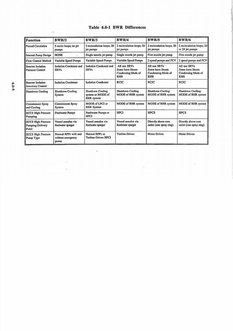
.TheBWR Differences chapter is provided togive the student. some. insight into the majordifferences between the various BWR product
"lines. Table 6.0-1 has been developed to allowcomparisons of various BWR functions for theproduct lines BWR/2 thi'ough BWR/6. The figuresin this chapter illustrate most of the more importantdifferences indicated in the tables.
6.0.1 Reactor Vessels
The reactor-vessel consists of the reactorpressure vessel, the components that support and"containthe core, and the components that provideflow paths and separation for steam and water.This section points out the differences in vesseldesign and construction pertaining to various flowpaths, ability to flood~the core following a loss of coolant accident,- and emergency core cooling
,system penetrations. ..
6.0.2 Recirculation and RecirculationFlow Control
- additional controller, a flux controller, that uses theaverage power range monitoring system as an input"tomaintain a desired powerlevel with core flow.
6.0.3 Reactor Isolation' Pressure and
Inventory Control .
In the event the reactorbecomes isolated from
its heat sink some component or system mustcontrol reactor vessel pressure and inventory. AllBWR plants have safety relief valves (SRVs) to-provide overpressure protection, and hence controlreactor pressure. -Some BWR facilities have
"-systems which can control .pressure withoutrequiring the use of the SRVs. All BWR facilitieshave a means of providing high pressure makeupwater to thereactor vessel to compensate forinventory loss via ihe pressure control method.
In the case of the BWR/2 product line andcertain plants of the BWR/3 product line, both of the isolation functions are carried out by a singlesystem called the isolation c6ndenser System. Theisolation' condenser system draws off reactor
- •steam, condenses the steam-in a condenser; andreturns th6 resultant condensite'to a recirculation
All operating BWRs use forced circulation of system suction line. By conserving inventory, th
'coolant, and hence all BWR reactor, vessels system eliminates the need for additional sources'* recirculation systems support this concept. The high pressure makeup.
way that forced circulation is achieved involves
differencesin the basic design. The BWR/2 design All BWRs of other,product lines use SRI
"hasno jet pumps inside the reactor vessel but has for pressure control and the reactor core isolaticfive external recirculation loops to provide the cooling system to provide high pressure makerrequired flow. The BWR/3 through BWR/6 water to the reactor vessel. Additionally, sondesigns do have jet pumps internal to the reactor BWR/4 product line plants, all BWRI5, andvessel and have only two external recirculation BWR/6 product line plants have another optic
loops., The jet pumps used in the BWR/5 and available. --The steam condensing mode of tU
BWR/6 product lines use a five nozzle design -residual heat removal system can be used f4
which is more efficient than the'single nozzle reactor pressure control. In this mode, 'react--design used in the BWR/3 and BWR/4 product steam is reduced in pressure and then condensed
lines. In the BWR/2, BWR/3 and BWR/4 product the-RHR heat exchanger where the resulta
lines core flow is controlled by changing the speed "'condensate is directed to the RCIC pump suction.of the variable speed recirculation pumps in each of ,
the recirculation loops.. - 6.0.4 Emergency Core Cooling Systems
isof
Irs
nip
neall
on
he
ororinnt
In the BWR/5 and BWR/6 product lines coreflow is controlled :by,. changing the dual speedrecirculation pumps from one discreet speed toanother and by throttling a variable position flowcontrol valve. ,-The recirculation flow control-system-for all product lines allows individual organged control of each flow control device. TheBWR/5 and BWR/6 product lines have an
--',The ECCS package provided for a particular"productline'is dependent primarily on the vintageof the plant. All BWP product lintes have highpressure and low pressure ECCSs. The BWR/2*product-line high pressure ECCS consists of the
- isolation condenser system and the aut6matic,depressurization system. Low pressure ECCSconsists of a core spray system.
USNRC Technical Training CenterKey iJY
,- G.E. Technology Advanced Manual - Differences/ Introduction
RKev .1195-- 6.0-1USNRC Technical Training Center

7/30/2019 Ml 023010606
http://slidepdf.com/reader/full/ml-023010606 4/92
G.E. Technology Advanced Manual. Differences/ Introduction
The BWR/3 product line high pressure ECCSpumping system consists of either a feedwatercoolant injection system or a high pressure coolantinjection system. The BWR/3 low pressure ECCSconsists of two core spray
loops and two lowpressure coolant injection, loops -either as aseparate system or as part of the residual heatremoval system.
The BWR/4 product line ECCS high pressurepumping consists of a high pressure coolantinjection system that delivers its flow to the vesselannulus.' The low pressure ECCSs consists of twocore spray system loops and two or four LPCIloops.
Th6 BWR/5 and BWR/6 product lines have
the same ECCS package. The ECCS high pressurepumping system consists of a high pressure corespray system. The low pressure ECCSs consistsof 'one low pressure core spray system loop andthree LPCI loops. The LPCS system is similar to asingle core spray loop -of the earlier BWR/4product line. The three LPCI loops deliver lowpressure flooding water directly inside the coreshroud.
6.0.5 Containment and Combustible GasControl
There are three containment packages used inthe various BWR product lines. All BWR/2,BWR/3, and early model BWR/4 product lineplants have the Mark I Containment. Later modelBWR/4 and all BWR/5"product line plants have theMark II Containment. All BWR/6 product lineplants have the: Mark IlI Containment. All threecontainments have the pressure suppressionfeature.
The Mark I Containment consists of adrywell (in the shape' of an inverted light bulb), asuppression chamber (in the shape of a toroid), and
a network of vents which extend radially outwardand downward from the drywell to the suppressionchamber. The drywell and suppression have thesame design'pressure.
- The Mark II-Containfment is sometimesreferred to' as an over-under containment. It,consists of a drywell (in-theshape of a truncatedcone) a suppression chamber directly below thedrywell (in the shape of a right circular cylinder),
and a netw0rk-'of vertical vents- extendingdownward from the drywell to the suppressionchamber: The drywell and suppression chamberhave the same design pressure.
The'Mark mI Containment- employs theconstruction simplicity of a dry containment whileretaining the advantage-of a pressure suppressiontype containment. The Mark'III Containmentconsists of a drywell (shaped like a right circularcylinder), a suppression pool (most of which isoutside but some of which is inside the drywell), aweir wall (that bounds the suppression pool on theinside of the drywell), and the containment vesselwhich is cylindrical with a domed head, completelysurrounds the drywell and suppression pool, and isboth a pressure boundary and a fission product
boundary.In the Mark I and Mark II Containment
designs, short term control of post LOCAhydrogen gas concentration is accomplished byinerting the primary containment with nitrogen gasfor normal plant operation. The nitrogen gas isused to displace the oxygen in the air and toprevent an explosive mixture of hydrogen andoxygen from forming. Long term control of postLOCA hydrogen gas concentration is accomplishedby adding additional nitrogengas and then ventingthe primary containment to the standby gas
treatment system. There are also hydrogenrecombinefs present in the BWR/5 design. Theyrecombine hydrogen gas and oxygen gas into watervapor.
In' the Mark III Containment design, shortterm control of post LOCA hydrogen gas is firstachieved because of the tremendously largervolume of the containment vessel (as compared tothe Mark I or Mark II designs). When drywellhydrogen gas concentiration starts to approach theflammability limit, drywell mixing compressors arestarted. They purgethe hydrogen gas from the
drywell into the containment. Long term control of post LOCA hydrogen gas concentration isaccomplished by hydrogen igniters, which aredistributed glow plugs similar to the ones used inPWR ice condenser containments.
Table 6.5-1 presents a comparison of thethree BWR containment types with regard to thesame or similar parameters.
USNRCTechnicalTrainingCenter6.0-2 Rev 1195USNRC Technical Training Center
G.E. Technology Advianced Manual, "I Differences/ Introduction
6.0-2 -Rev 1195

7/30/2019 Ml 023010606
http://slidepdf.com/reader/full/ml-023010606 5/92
G.E. Technology Advanced Manual Differencesi Introduction
6.0.6 Rod Control
Rod control for plants of the BWR/2 throughBWR/5 product lines consists of a reactor manualcontrol system (RMCS). The RMCS uses relays,
contacts, and timers. The BWR/5 RMCS issomewhat of a hybrid between the system used inBWR/2 through BWR/4 and the BWR/6. Thesystem used in the BWR/6 product line is called theRod control and information system which is asolid state time multiplexing system. The RMCSfor the BWR/2 through the BWR/5 product linesallows movement of only a single control rod at atime. The BWR/6 RC&IS allows movement of control rods one at a time or in a gang mode of upto four at a time.
6.0.7 Balance of Plant Systems
The balance of plant systems used in thevarious BWR product lines are too numerous tocover in detail. Section 6.7 deals with the twomost common types of condensate and feedwatersystems and the feedwater control system.
6.0.8 Safety Relief Valves
Safety relief valves prevent the overpressurization of the nuclear process barrier fromabnormal operation transients. The various safetyrelief valves used through out the BWR productlines are discussed in this section.
USNRC Technical Training CenterRev 119
G.E. Technolo--y Advanced Manual Differences/ Introduction
Rev 1195USNRC Technical Training Center
7/30/2019 Ml 023010606
http://slidepdf.com/reader/full/ml-023010606 6/92

7/30/2019 Ml 023010606
http://slidepdf.com/reader/full/ml-023010606 7/92
Table 6.0-1 BWR Differences
Function BWR/2 BWR/3 BWR/4 BWR/5 BWR/6
ECCS Blowdown ADS ADS ADS ADS ADS
ECCS Low Pressure Two core spray Two core spray Two core spray One LPCS loop One LPCS loop
Spray(independent) loops (independent) loops (independent) loops
ECCS Low Pressure NONE LPCI sys, 2 loops; or LPCI MODE of RHR, LPCI MODE of RHR, LPCI MODE of RHR,
Flooding LPCI MODE of RHR 2 independent loops 3 independent loops 3 independent loops(2 plantshave 4 loops)
ECCS Low Pressure Recirculation pump Recirculation pump Inside core shroud, core Inside core shroud, core
Flooding Deliver point discharge pipe discharge pipe or inside region regionshroud (core region)
Standby Coolant UHS to condenser and From UHS to Feedwater Form UHS to RHR Form UHS to RHR Form UHS to RHR
Supply then feedwater to vessel or RHR
Containment Package Mark I Mark I Mark I or II Mark II Mark III
Primary Containment Drywell and Drywell and Drywell and Drywell and Containment
Fission Product Barrier Suppression Pool Suppression Pool Suppression Pool Suppression Pool
Hydrogen Control Nitrogen inerting during Nitrogen inerting during Nitrogen inerting during Nitrogen inerting during Larger volume; mixing
Short Term normal operation normal operation normal operation normal operation compressors
Hydrogen Control Long Nitrogen inerting; Nitrogen inerting; Nitrogen inerting; Nitrogen inerting; Hydrogen recombiners;
Terms venting to SGTS venting to SGTS venting to SGTS; venting to SGTS; hydrogen ignitersrecombiners Recombiners
Rod Control RMCS; one rod at a RMCS; one rod at a RMCS; one rod at a RMCS; one rod at a RC&IS; up to four rods
time; standard relays and time; standard relays and time; standard relays and time; solid state at a time; Solid state
timer timer timer or solid state
!

7/30/2019 Ml 023010606
http://slidepdf.com/reader/full/ml-023010606 8/92
Table of Contents
6.1 REACTOR VESSELS ..................................................................................... 16.1.1 Introduction ......................................................................................... 1
6.1.2 BWR/2 Reactor Vessel ............................................................................. 1
6.1.2.1 Vessel Internals ........................................................................... 1
6.1.3 BWR/3 and BWR/4 Reactor Vessels ............................................................ 3
6.1.3.1 BWR/4 Advanced Vessel Design .................................................... 3,
6.1.4 BWR/5 and BWR/6 Reactor Vessel ............................................................ 3
6.1-5 Summary ......................................................................................... 3
List of Figures
6.1-1 BWR/2 Reactor Vessel ................................................................................ 5
6.1-2 Reactor Vessel (BWR/3 orBWR/4) ................................................................ 7
6.1-3 Reactor Vessel (BWR/5 orBWR/6) ................................................................ 9
USNRC Technical Training Center '1.1-I KCV U1Y
G.E. Technology Advanced Manual Differences/Reactor Vessel
USNRC Technical Training Center 0.1-i Rev 01953

7/30/2019 Ml 023010606
http://slidepdf.com/reader/full/ml-023010606 9/92
G.E. Technoloav Advanced Manual Differences/Reactor Vessel
6.1 REACTOR VESSELS
-Learning Objectives:
After studying this section, you should be able to:
1. Describe the internal components and their- arrangement that may or may not provide 2/3
core coverage'capability following a LOCA.
I6.1. Introduction
-The -reactor vessels utilized for a particularproduct-line are dependent 'on the vintage of theplant, core cooling regulations, type of recirculation system,- and technology used during 'itsperiod of design. The reactor vessel houses thereactor core, serves as part of the reactor coolant
,boundary, -supports -and aligns the fuel andcontrol rods,' provides a flow .iaath for -the
-circulation of coolant past the fuel, removesmoisture from the steam exiting the reactor vessel,limits the downward control rod motion followinga postulated failure of a control rod drive housing,and in all cases except the BWR/2 product lineprovides an internal refloodable volume followinga loss of coolant accident.
6.1.2 BWR/2 Reactor Vessel
The BWR/2 reactor -vessel, Figure 6.1-1; isan insulated pressure vessel mounted veitically
,.within the drywell and is comprised ,of acylindrical shell -with an integral hemisphericalbottom head. The top head is also hemispherical-but is removable to facilitate refueling operations. "The base materialof the vessel is high strengthalloy carbon steel. All internal surfaces includingthe shell, heads, flanges and attachments are clad
-.with Type 304 stainless steel to a thickness of 0.25 inches. .Small nozzles which are notpracticable to clad internally with stainless overlayare solid nickel-chromium-iron alloy.
The vesselhead is attached to the vessel shell
by sixty four six inch diameter studs that arethreaded into bushings in the vessel flanige.Spherical washers and, closure nuts are matchmarked in sets of two and are used in sets.- Tosecure the head to the vessel shell, the'stuids 'are-elongated iby, hydraulic stud, tensioners which
,,permit the nuts to be turned while the stud is, under tension. -
Leakage of radioactive coolant and steambetween the mating surfaces of the' vssel andclosure head flanges to atmosphere is containedby tvo self-energizirig 0-ring gaskets. Thesesilver plated and polished Ni-Cr-Fe- (Inconel)
0-rings are -approximately 0.50 inches indiameter. The 0-rings are designed to have nodetectable leakige throuigh'the inner or outermember during any reactor operating condition.
6.1.2.1 Vessel Internals
The major reactor vessel internal com-onentsincluded in this discussion are the core supportassembly, core shroud, diffuser, core plate, uppercore grid, core spray system sparger, feedwatersparger, stean separators and dryers.
Core Support Assembly
The core suppfort assembly c0nsists of astainless steel forged ring that is welded to anInconel segment. The Inconel segment is weldedto the lower shell of the vessel. The core supportassembly supports the core shroud and separatesthe re'circulation osystemr- suction l'-from its
discharge...
Core Shroud
The core shroud is supported by the core sup
port assembly. The core shroud along with thecore support assembly forms a- 17 inch waterannulus inside the reactor vessel wall. Inaddition, a-flow barrier is provided by the lowerportion of the shr6ud ifid the support assembly.This conical skirt, welded to the reactor vesselwall, effectively separates the recirculation inletcore flow from the downcomer annuluý flowV.
Diffuser .
The vessel diffuiser is a eliridrieal shellhanging downward from a shelf prbvided by a
ring girder. The diffuser contains hundreds of 1.25 inch diameter holes and'is approximatelyeight feet in height., The diffuser serves a twofold purpose; it~prevents' direct contact of therecirculation flow.to the control rod guide tubes
-and provides a uniiform flowA of coolant lelow thefuel oi'ifice region.'-* . . ' -
USNRC Technical Training Center 0.1-1 Rv uL,I--0.1-1
-G.E. Technology Advanced Manual - Differences/Reactor Vessel
Rev 0175S USNRC Technical Training Center

7/30/2019 Ml 023010606
http://slidepdf.com/reader/full/ml-023010606 10/92
G.E. Technology Advanced Manual Differences/Reactor Vessel
Core Plate
The core plate is provided to laterally guideand align the control rod guide.tube and fuel
support castings. Twelve peripheral fuelassemblies, located outside the control rod patternare supported vertically by the core plate. Theseperipheral fuel assemblies rest in a fuel Supportpiece that is welded to the core plate. The coreplate prevents recirculation flow from bypassingthe fuel assemblies by directing the flow into thecontrol rod guide tube.
Upper Core Grid
The upper core grid or top guide is mountedand supported by tweNe brackets inside the
shroud. Eight bolts are provided to laterallyposition and level the top guide. F6u'r hbld downbolts attach the top guide to the ledge of the coreshroud.
Core Spray Sparger
TWo' independent core spray loops areinstalled in the vessel above the upper core grid(top guide) and within the core shroud. Theloops are connected to the Core Spray Systemwhich is used for core cooling 'under loss of coolant accident conditions.
Feedwater Sparger
The feedwater spargers are m6unted to thereactor vessel wall in- the upper part of thedowncomer or annulus region. The spargers,each supplied by one of -the two feedwaternozzles, complete a half, circle of the vesselinterior and discharges water radially inward. Anumber of 1-inch holes in each sparger permitsthe cooler feedwater to mix with downcomerrecirculation flow before coming in contact withthe vesiel.
Steam Separator
The steam separator assembly consists of theshroud head and an array of. standpipes withsteam separators located above each sutndpipe.-The shroud head mates with the core shroud andis bolted to it. The shroud head is a dished'unitand forms the cover of the core discharge plenumregion. A metal to metal contact seals the
separator assembly and the core shroud flange.Operation of the steam separators is identical tothat of the separators covered in the systemsmanual.
Steam Dryer
The steam dryers are required- to dry a massflow of wet steam at 1015 psia and 10percentmoisture by weight to a mass flow of dry steam at1015 psia and 0.10 percent moisture by weight.The mass flow of steam ranges from zero to6,933,000 pounds per hour. The dryer assemblyis supported by four internal vessel pads. Verticalguides inside the vessel provide alignment duringinstallation, four hold down bolts hold the unit inposition.
The dryer assembly is mounted in the vesselabove the steam separator assembly and forms thetop and sides of the'wet steam plenum. Steam thathas passed through the separators enters thechevron-type dryier units. A series of troughs andtubes remove the remaining moistuie which flowsinto the downcomer annulus.
6.1.3 BWR/3 and BWR/4 ReactorVessels
The introduction of the BWRI3 product line
(Figurer-6. 1-2) produced major changes in thereactor vessel design. One of the more importantchanges ,wasthe elimination of the five recirculation loop concept in favor of two loops with'jetpumps-mounted internal to the reactor vessel. Theeliinnation of five loops removed the recirculationsystem discharge nozzle penetrations in the vesselbottom head region and reduces the probability of a large break loss of coolant accident. Thei installatibn of the jet pumps provides a standpipeeffect so the core can be reflooded, following aloss of coolant' accident and allows bettercommunication between the annulus region and
the core region without the need of the recirculation loops.
The BWR/3 product line vessel also includedmodifications to the feedwater spargers, steamdryers, vessel head, and, the cladding overlay.The feedwater spargers increased in number fromtwo' to four and contain converging nozzles forbetter efficiency and extended sparger life.' Thedryer assembly retained the same operating
USNRC Technical Training Center 6.1-2 Rev 019S
G.E. Technology Advanced Manual Differences/Reactor Vessel
USNRC Technical Training Center 6.1-2 Rev 0195

7/30/2019 Ml 023010606
http://slidepdf.com/reader/full/ml-023010606 11/92
G.E. Technolo!y Advanced Manual Differences/Reactor Vessel
principle but, added more drying units and wasno longer bolted down. The vessel head gainedtwo new penetrations (head spray and spare), inaddition to holddown pads to prevent the steamdryer from lifting during system operation. The
vessel upper head and nozzle penetration are notclad because it is not needed and the claddingtended to propagate cracks into the base metal onnozzle penetrations.
6.1.3. BWR/4 Advanced Vessel Design
Two BWR/4 product line vessels favor thelater BWR/5 and BWR/6 design in that theycontain separate and independent penetrations forthe Low Pressure Coolant Injection (LPCI) modeof the Residual Heat Removal System. The LPCIinjection lines penetrate the vessel at four different
locations and continue until they penetrate the coreshroud.
6.1.4 BWR/5 and BWR/6 ReactorVessel
The BWR/5 product line (Figure 6.1-3)produced changes in the vessel upper head, steamseparator and dryer assemblies, instrumentationquadrant taps, and LPCI injection penetrations.The upper yessel head penetrations was reducedfrom three to only two, one spare and onemultipurpose to perform the functions previouslyperformed by two separate penetrations. Thesteam separator assembly acquired moreseparating units as did the dryer assembly. Thedryer assembly also under went holddownchanges to eliminate the problem of ensuring itwas disconnected from the core shroud prior tolifting. The LPCI injection penetrations werereduced from four to three.
6.1.5 Summary
The reactor vessels utilized for a particularproduct line are dependent on the vintage of theplant, core cooling regulations, type of recircula
tion system, and technology used during itsperiod of design. The reactor vessel houses thereactor core, serves as part of the reactor coolantboundary, supports and aligns the fuel andcontrol rods, provides a flow path for thecirculation of coolant past the fuel, removesmoisture from the steam exiting the reactor vessel,limits the downward control rod motion followinga postulated failure of a control rod drive housing,and in all cases except the BWR/2 product lineprovides an internal refloodable volume followinga loss of coolant accident.
S... . -" -t,T,11 --.. frl fl
G.E. Technology Advanced Manual Differences/Reactor Vessel
Rt•ev 019 aUSNRC Technical Training Center

7/30/2019 Ml 023010606
http://slidepdf.com/reader/full/ml-023010606 12/92
497-6
VENT
REACTOR VESSEL HEAD
STEAM DRYER ASSEMBLY.
STEAM OUTLET NOZZLE
WATER LEVEL
MEASUREMENT TAPS-c
SEPARATOR ASSEMBLY
HOLD DOWN BOLT
FEEDWATER SPARGER
CORE SPRAY NOZZLE
CORE SPRAY SPARGER
UPPER CORE GRID
CORE1
VESSEL HEAD NUT
VESSEL FLANGE
S-STEAM PRESSUREMEASUREMENT TAP
STEAM SEPARATOR
STEAM SEPARATOR STEAM
STANDPIPE SEPARATOR
STEAM PLENUM HEADJASSEMBLY
FEEDWATER INLET NOZZLE
CONTROL ROD
RECIRCULATING WATEROUTLET NOZZLE
CORE DIFFERENTIALPRESSURE TAP
-VESSEL SUPPORT SKIRT
A
IN-CORE MONITORCONTROL ROD DRIVEHOUSING
Figure 6.1-1 BWR/2 Reactor Vessel
6.1-5

7/30/2019 Ml 023010606
http://slidepdf.com/reader/full/ml-023010606 13/92
HEAD SPRAY
COOLING NOZZLE.
REACTOR VESSEL HEAD
DYER ASSEMBLY
LIFTING LUGS
STEAM DRYERASSEMBLY
STEAM OUTLET NOZZLE
SHROUD HEAD
LIFTING LUGS
DYER SEAL SKIRT
CORE SPRAY
SUPPLY HEADER
SHROUD HEAD
HOLD-DOWN BOLTS
JET PUMP INLET ELBOW
AND NOZZLE ASSEMBLY
IN-CORE FLUX MONITOR
ASSEMBLY
RECIRCULATING WATER
INLET NOZZLE
JET PUMP INLET RISER
JET PUMP DIFFUSER
-STEAM DRYER ANDSHROUD HEAD ALIGNMENTAND GUIDE RODS
-STEAM SEPARATOR AND
STANDPIPE ASSEMBLY
-FEEDWATER INLET
-FEEDWATER SPARGER
*RECIRCULATING WATEROUTLET NOZZLE
"CONTROL RODGUIDE TUBE
CONTROL ROD DRIVE HOUSING
SUPPORT STRUCTURE
Figure 6.1-2 Reactor Vessel -(BWR/3 or BWR/4)
6.1-7

7/30/2019 Ml 023010606
http://slidepdf.com/reader/full/ml-023010606 14/92
497.6
VENT AND HEAD SPRAY
STEAM OUTLET
CORE SPRAY INLET
JET PUMP ASSEMBLY
JET PUMP/RECIRCULATION
WATER INLET
STEAM DRYER LIFTINGLUG
- STEAM SEPARATOR
ASSEMBLY
- FEEDWATER INLET
FEEDWATER SPARGER
LOW PRESSURE COOLANT
INJECTION INLET
Figure 6.1-3 Reactor Vessel (BWR/5 OR BWR/6)
6.1-9

7/30/2019 Ml 023010606
http://slidepdf.com/reader/full/ml-023010606 15/92
Table of Contents
6.2 RECIRCULATION AND FLOW CONTROL SYSTEMS 16.2.1 Introduction ........................................................................................... 1
6.2.2 BWR/2 ............................................................................................... 1
6.2.2.1 Recirculation System ..................................................................... 1
6.2.3 BWR/3&4 ............................................................................................. 3
6.2.3.1 Recirculation System ..................................................................... 3
6.2.3.2 Rcirculation Flow Control ............................................................. .4
6.2.3.3 Recirculation Pump Start ................................................................. 5
6.2.3.4 Power/Flow Map ......................................................................... 6
6.2.4 BWR/5-6 ............................................................................................. 6
6.2.4.1, Recirculation System ..................................................................... 6
6.2.4.2 Recirculation Pump Speed Control ..................................................... 7
6.2.4.3 Recirculation Flow Control ............................................................. 8
6.2.4.4 Power/Flow Map ......................................................................... 9
6.2-5 Summary ............................................................................................ 9
List of Figures
6.2-1 BWR/2 Recirculation System ..................................................................... 11
6.2-2 RFC System (BWR/2, BWR/3, & BWR/4) .................................................... 13
6.2-3 Recirculation System (BWR/3 or4) ............................................................ 15
6.2-4 Recirculation'Flow Control Logic (BWR/3 & BWR/4) ..................................... 17
6.2-5 Recirculation Pump M/G Start Sequence ........................................................ 19
6.2-6 Power/Flow Map (BWR/3 & BWR/4) ......................................................... 21
6.2-7 Recirculation System (BWR/5 & BWR/6) ...................................................... 23
6.2-8 Recirculation Pump Power Supply (BWR/5 & BWR/6) ....................................... 25
6.2-9 BWR/5 & BWR/6 Slow Speed Start Sequence ................................................. 27
6.2-10 RFC (BWR/5 & BWR/6) ........................................................................ 29
6.2-11 RFC (BWR/5 & BWR/6) continued ............................................................ 31
6.2-12 Power/Flow Map (BWR/5 & BWR/6) ......................................................... 33
USNRC Technical Training CenterRev U497
G.E. Technolog~y Advanced Manual Differences/Recirc & RFC
6.2-i Rev 0497USNRC Technical Training Center

7/30/2019 Ml 023010606
http://slidepdf.com/reader/full/ml-023010606 16/92
G.E. Technology Advanced Manual Differences/Recirc & RFC6.2 RECIRCULATION AND FLOW
.,6.2 ýRECIRCULATION AND FLOW,CONTROL SYSTEMS
'Learning Objectives :
1. Explain the three different types of recircula
S,._tion loops.
"2.--2 Explain valve vs. pump flow control.
3. Explain the thermal shock limitation.
4. Explain the power/flow map.
S6.2.1Introduction'
The Recirculation System provides variabl
forced circulation of, water, through the core
thereby allowing a higher power level to b
achieved than with natural circulation alone. Th
TRecirculation -System,-in conjunction with th
Recirculation Flow Control System, provides
,relatively. rapid means of controlling reactor powe
_over a limited range by adjusting the rate of coolarflow through the core.
SControl rod movement and recirculation flo•
adjustment are the two means of controlling reactcpower under normal operating conditions. Contrc
rod motion produces local changes in reactivity an- -neutron flux, while recirculation flow adjustment
-produce changes in-flux across the core withotsignificantly affecting local to average flux values.
An increase in recirculation flow produces a
increase in total core flow, or an increase in maw
flow rate of subcooled fluid -entering the con
This increase in-flow suppresses boiling sinc
additional heating is required to reach saturatiolThe boiling boundary moves upward and the voivolume decreases. The resulting positive reactivit
increases core power. Power continues to increa&
until the boiling boundary and void fraction a
restored and core reactivity returns to zero. TI- reverse mechanism occurs on a recirculation fto
.'decrease. In both cases, void fraction changes a
transient and void fraction is eventually returned to-near the beginning value. The doppler coefficientproduces the slight difference in void fraction
because of changes in fuel temperature.
6.2.2 BWR/2
The Recirculation System for BWR/2 product
lines, Figure 6.2-1, consists of five parallel piping
-loops, designated A through E. The pumping
loops take suction from the reactor vessel
downcomer annulus and discharge to the lower
head area beneaththe fuel region. The operator
adjusts recirculation flow rate -by varying thevoltage and frequency output of motor generatorsets which supply power to the recirculation pump
e motors.
e 6.2.2.l1Recirculation -Systemee The five recirculation pumps, - arranged in
a parallel, take suction from the reactor vessel
r downcomer annulus through individual outlet
at nozzles and motor operated suction valves. Pump
,discharge flow, passes through individual motor
:operated discharge isolation valves an'd reenters the;v reactor vessel through five inlet nozzles. A 2 inch
r line containing a motor operated valve bypasses31 each pump discharge valve. -This path allows a
d - minimum flow during pump starting and providests - a small backflow to keep an idle loop warm.it
All five recirculation loops are normally in
... operation, with the pumps at the same speed.n -Under certain--conditions, plant operation is
s,,- permitted with one loop idle, but not isolated.
e - Various other plant systems that connect to the
1. recirculation system include: .. -
y - . -A10 inch line joins loop A upstream of
se the pump suction valve to provide a
re , -,- -- return flow path to the reactor vessel from
e - isolation condenser A.
-USNRC Technical Training Center 6.2-1 - - Rev 04Y7
G.E. Technolo~v Advanced Manual IDifferences/Recirc & RFC
"•"USNRC Technical Training Center S. •-- _ " - •Rev 04976.2-1

7/30/2019 Ml 023010606
http://slidepdf.com/reader/full/ml-023010606 17/92
SADifferences.R.circ . RFC
"* A 3/4 inch line taps off loop A upstreamof the pump suction valve to provide aflow path to the sampling system.
"* Two 6 inch lines connect to loop B toprovide supply and return flow for theReactor Water Cleanup System.
" Two 14 inch lines connect to loop E toprovide supply and return flow for theShutdown Cooling System.
"* A 10 inch line joins the 14 inch shutdowncooling supply line to provide a returnflow path to the reactor vessel from
isolation condenser B.
The major components of the RecirculationSystem are discussed in the paragraphs that follow.
Recirculation Pumps
The recirculation pumps provide the driving"headfor the recirculati6n system. Each pump is avrtical; single stage, centrifugal pump driven by a1000'HP, variable speed induction motor. Thepumps are powered from individual M/G setswhich supply a variable frequency and voltage(11.5 - 57.5 Hz and 460-2300 volts) to changepump speed and flow rate. The flow rate per pumpvaries from a minimum of 6400 gpm to amaximum of 32,000 gpm.
Each recirculation pump is equipped with adual seal assembly which contains reactor waterwithin the pump casing and associated controlledleakage lines and allows zero leakage to the
,primary containment The assembly consists of
two seals built into a cartridge that can be'replacedwithout removing the motor from the pump. Eachseal can 'vithsiand full"puimp design pressure sothat either will adequately limit leakage if the otherfails. A breakdown bushing in the pump casinglimits leakage to approximately 60 gpm if both
seals fail.
During noiimal operation, both seals share thesealing work load of the assembly, with approximately a 500 psid pressure drop across each seal.Thus, seal cavity #1 is at reactor pressure and seal
cavity #2 is at one half of reactor pressure. Thisarrangement -is maintained by two internalrestricting orifices which control the leakage
between the seal cavities, and from cavity #2 to thedrywell equipment drain tank (DWEDT), atapproximately 0.5 gpm. A flow switch in thecontrolled leakage line actuates an alarm on sealfailure (high flow) or orifice plugging (low flow).
The seal cavities require forced cooling toremove heat generated by friction between the seal
ing surfaces. The Reactor Building ClosedCooling Water System supplies approximately 25gpm of water to a heat'exchanger surrounding theseal cartridge. Reactor'water from the pump cavitypasses through a hole in the main pump impeller,around the hydrostatic bearing, and through theshaft to casing •learanice to an auxiliary impellerlocated just below the seal cartridge. The auxiliaryimpeller forces the seal water through'the tubes of the heat exchanger.
BWR/2 Recirculation Flow ControlSystem,
Each recirculation pump is hardwired to anassociated recirculation motor/generator (M/G) setstator. (Figure'6.2-2) Since the pumps are drivenby an induction motor, pump speed and resultingrecirculation loop flow are determined by generatorspeed (frequency).
Each M/G set consists of a constant speed drivemotor, a fluid coupler, a variable speed generator.
The speed of the generator is determined by thegenerator load and the amount of coupling betweenthe drive motor and generator.
Scoop tubes vary the volume of oil in the
hydraulic coupler, and thus the amount of torquetransmitted from the drive motors to the generators.As a scoop tube is inserted, the volume of oil in the
USNRC Technical Training Center 6.Z-2 Rev 0497
G.E. Technoloav Advanced Manual
USNRC Technical Training Center 6.2-2 Rev 0497

7/30/2019 Ml 023010606
http://slidepdf.com/reader/full/ml-023010606 18/92
-G.E.. Technology Advanced Manual DifferenceslRecirc & RFC
coupler decreases, and both torque transmissionand generator speed decrease.. Pump speed also
decreases, since the pump operates synchronouslywith the generator. Likewisei oil volume,
generator speed and pump speed all increase as ascoop tube is retracted.
The flow control system contains one speed
control loop for each of the five recirculation
pumps. Manual speed demand signals are sent tothe -five"controllers fr6m two sources during
-normal operation:.
In the master/manual mode of operation,
a single speed demand signal originatingin the master controller passes through
-each :M/A transfer station to the speed
controllers. All recirculation pumps
operate at approximately the same speed,
as determined by the master controller.* - The automatic position of te'-master
controller is not used and the controller ispinned in the manual position.
* In the loop n manual mode of operation,the master controller is disconnected, and
pump speed is controlled individually by
speed demand signals originating in each. 'M/A transfer station.
The speed controllers compare speed demand
signals from the M/A transfer stations to speed
feedback from the M/G set tachometers. The
resulting error signals are supplied to the Bailey,
"scooptube positioners, which position the M/G set
hydraulic coupler scoop tubes. Feedback signals
from the scoop tube actuators and speed tachome
ters'stop motion when scoop tube positions are
correct.
6.2.3- BWRI3&4
The recirculation system for BWRs 3&4
(Figure 6.2-3) consists of two piping loops
external to the reactor vessel and 20 jet pumpswhich are internal to the reactor vessel. Each loop
has a suction isolation valve, recirculation pump,a discharge isolation valve, instrumentation, andpiping connecting to the reactor vessel.
The variable speed recirculation pumps takesuction from the reactor vessel annulus region andprovide flow to the jet pump riser pipes through the
reactor vessel shell. The jet pumps induce
additional water fromthe reactor vessel annulus
region into the flow path, increasing system
efficiency.
-6.2.3.1 , Recirculation System,
The major parts of the recirculation system arediscussed in the paragraphs that follow.
Suction Valve
There is a suction valve in each recirculationloop between the reactor vessel penetration and the
recirculation pump. These motor operated suction
valves are used for maintenance isolation of each
recirculation pump..
"Recirculation Pump
The recirculation pumps are vertical, single"stage,centrifugal pumps driven by a variable speed
electrical motor. The pumps provide a rated flow
of 45,200 gallons per minute each. The speed of
the recirculation pumps, and hence the sy'stem flow
rate, is controlled by the recirculation flow control
system.
Discharge Valve
Each recirculation loop contains a motor
operated discharge valve located between therecirculation pump and the loop flow measurementdevice.-The valve is remotely' operited from the
control room using a seal-in to close, throttle to
open logic. The discharge valves are automatically
jogged open on a pump startup by the recirculation
-flow control system. Additionally, the dischargevalves close as part of the automatic initiation
§USNRC Technical TrainiDg CenterKey U4YJ
1,,ý G.E. -Technology Advanced Manual - Differences/Recirc & RFC
-- R~ev 04-7S" USNRC Technical Training Center- 6.2•-3-

7/30/2019 Ml 023010606
http://slidepdf.com/reader/full/ml-023010606 19/92
G.E. Technology Advinced Manual DifferenceslRecirc & RFC
sequefice for low pressure coolant injection modelogic of the Residual Heat Removal System to
provide an emergency core cooling flow path to the
reactor vessel. (See Chapter 6.4)
Jet Pumps
There is a bank of 10 jet pumps associated witheach of the external'recirculation loops. All jet
pumps are located in the reactor vessel annulusregion between the inner vessel wall and the coreshroud. The jet pumps are provided to increase the
total core flow while minimizing the flow externalto the reactor vessel.
Each jet pump has a converging nozzle throughwhich the driving flow passes. This creates a highvelocity and relatively low pressure'condition at the
jet pump suction. This low pressure conditioncreates additional flow from the vessel annulus,called induced flow, through the jet pumps. Thecombined flows mix in the mixer section'of the jetpumps and then pass through the diffuser section.The diffuser section increases the pressure anddecreases the fluid velocity. During full poweroperation approximately one-third of the total core
flow comes fromthe
dischargeof the recirculation
pumps while the remaining two-thirds is inducedby the jet pumps.
6.2'.3.2 Recirculation Flow Control
The major components of the recirculation flowcontrol system are discussed in the paragraphs thatfollow (Figure 6.2-4).
Recirculation Motor Generator Set
The recirculation motor generator set- consistsof a drive motor, fluid coupler, generator, and thenecessary auxiliary components to support motorgenerator set operation.
The recirculation motor generator set drivemotor is'a constant speed motor with a horsepower rating between 7,000 and 9,000 HP. The
drive motor supplies the fluid coupler with motiveforce through a constant speed input shaft.
The fluid coupler transmits a portion of the
drive motor torque to the generator shaft. Theamount of torque that is transmitted to the generatoris determined by the coupling between the drivemotor and generator, which is determined by the
amourit'of oil in the fluid coupler. The quantity of oil in the fluid coupler is regulated by the positioning of a device called a "scoop tube". The greaterthe quantity of oil in the fluid coupler the greaterthe coupling between the generator and drivemotor. Therefore, the scoop tube position
determines the t6rque transmitted to the generator.
Recirculation Pump Speed Control Logic
The principle of operation in the flow control16gie is to set a desired speed, measure the actualspeed, compare these signals and produce a controlsignal used to position the scoop tube to obtain thedesired speed. The components performing thisfunction are discussed in the paragraphs that
follow.
Master Flow Controller
The master flow controller provides the meansof controlling both recirculation motor generatorsets from a single controller. Normal operation of the master controller is in the manual mode of
operation. By adjusting the manual potentiometer,a demand signal is developed and transmitted to the
manual automatic (MIA) transfer station via a duallimiter.
In the automatic mode of operation the electro
hydraulic control system provides the desired maingenerator set load demand signal. Only one utility,Commonwealth Edison, has operated in theautomatic mode and is licensed to do so.
USNRC Technical Training Center 6 .2-4 Rev 0497
G.E. Technology- Advanced Manual Differences/Recirc & RFC
USNRC Technical Training Center 6.2-4 Rev 0497

7/30/2019 Ml 023010606
http://slidepdf.com/reader/full/ml-023010606 20/92
G.E. Technology Advanced Manual Differences/Recire & RFC
Manual-Automatic Transfer StationControllers
The MWA transfer station controllers provide t]
means -of controlling the motor/generator sindependently, or as a paired unit. -Similarto ti
master controller, the M/A transfer stations conta
two modes of operation, manual and automati
Normal .mode of operation is both controllers
automatic.
Speed, Limiters
There are two speed limiters used in the contr
logic to limit the maximum and/or minimum sped,demand signal according t6 plant conditions.
The output of the M/A station controller
routed through two speed limiters. The first
these limiters limits recirculation pump speed to
maximum of 28% with the pump discharge vallnot full open or feedwater flow less than 20W
This limiter prevents overheating of the recircul
tion pumps with the discharge valve not open ai
cavitation problems for the recirculation pumps a- jet pumps at low feedwater flow rates.
Thesecond limiter, operational limiter, limthe maximum recirculation pump speed demand
-less than that required for approximately 75power. This limit ensures a sufficient supplyfeedwater to the reactor vessel to maintain t
required operating level. This limiter is bypasswhenever level is normal or if all reactor fe
"pumpsare in service. The operational limiter
supplied to plants with turbine driven feed puml
Plants .with-motor driven feed pumps andautomatic startup of the standby pump do r
require a load reduction to maintain level.
Speed Control Summer
The speed control summer, during. norrr
operation; compares the speed demand signal to I
actual generator speed and develops an error sigiwhich is sent to the speed controller. The en
signal is limited to about 8% of the control band.
""Speed Controller,
e-t., ,o -,Thespeed controller establishes and maintainsie a speed demand signal in accordance with the error
in signal received from the speed control summer.
c.
in - Scoop Tube Positioner
The scoop tube poiitioner converts the
-electrical input signal, from the speed controller, to
a mechanical scoop tube position.
-d 6.2.3.3 Recirculation -Pump Start
Figure 6.2-5 lists the initial requirements and
is -sequence of events occurring on a recirculationof motor-generator startup. Briefly, the drive motora starts if all of the permissives are satisfied. If the
ve scoop tube is in the proper position and the pump
%. is not developing any differential pressure, a 7
a- second time delay is initiated after which the field
[Id breaker closes., During this time delay, the drive
rid ,motor and generator are accelerating to approximately 12% loaded speed; this corresponds to 40%
unloaded speed.,
itsto Note on Figure 6.2-4 that when the field
% breaker is open, the speed control system input toof the error limiter is replaced by the signal generator,hie .and the tachometer feedback by the speed controller
ed output. -This serves to position the scoop tube to
ed the 40% unloaded position. Excitation is applied to
is _the motor generator set exciter 5 seconds after the)s., drive motor breaker is closed.aniot Excitation is provided from the 120 VAC
startup excitation source. Thus, when the field* breaker closes 7 seconds after the drive motor
*breaker closure, the motor, generator set is
'accelerated to approximately 40% unloaded speed
ial and fully excited to provide the necessary pump
he -breakaway torque.
USNRC Technical Training CenterKCV U4YT/
G.E., Technology Advanced Manual Differences/Recirc & RFC
";Rev 04!V/6.2-5USNRC Technical Training Center

7/30/2019 Ml 023010606
http://slidepdf.com/reader/full/ml-023010606 21/92
7/30/2019 Ml 023010606
http://slidepdf.com/reader/full/ml-023010606 22/92
G.E. Techno1oy Advanced Manual Differences/Recirc & RFCregion where it mixes with the moisture returning
region where it mixesmwith the moisture returning_from the steam separation stages.
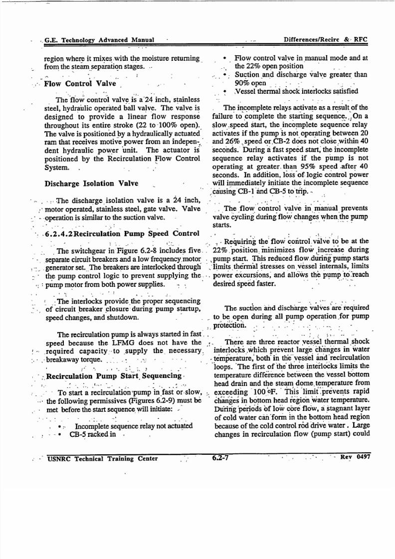
Flow Controi Valve
The flow control valve is a24 inch, stainless
steel, hydraulic operated ball valve. The valve is
designed to provide a linear flow response
throughout its entire stroke (22 to-100% open)..
The valve is positioned by a hydraulically actuatedram that receives motive power from an indepen
dent hydraulic power 'unit. The actuator is
positioned by the Recirculation Flow Control
System. ,
Discharge Isolation Valve
The discharge .isolation valve is a 24 inch,
:' motor operated, stainless steel, gate valve. Valve
-_operation is similar to the suction valve.
"6.2.4.2Recirculation Pump Speed Control
The switchgear in Figure 6.2-8 includes five.
-separate circuit breakers and a low frequency, motor,* generator set. The breakers are interlocked through
- the pump control logic to prevent supplying the
* pump motor from both power supplies.
The interlocks provide the proper sequencingof circuit breaker closure during pump startup,
speed changes, and shutdown.
The recirculation pump is always started in fast,
speed because the LFMG does not have the
required capacity -to supply the, necessary.
breakaway torque. - .
Recirculation Pump Start Sequencing,
th To start a recirculation,pump in fast or.slow,
the following permissives (Figures 6.2-9) must be
met before the start sequence will initiate:
*=Incomplete sequence relay not actuated* CB-5 racked in
* Flow control valve in manual mode and atthe 22% open position
Suction and discharge valve greater than
90% open -
,Vessel thermal shock interlocks satisfied
The incomplete relays activate as a result of the
failure to complete the starting sequence..,, On a
slow.,speed start, the incomplete sequence relay
activates if the pump is not operating between 20and 26% .speed orCB-2 does not closie within 40
seconds. During a fast speed start' the incomplete
sequence relay activates if the pump is not
operating at greater, than 95% speed after 40
seconds. In addition, loss of logic control powerwill immediately initiate the incomplete sequence
-causing CB-1 and CB-5 to'tip.
The flow control valve in manual prevents
valve cycling during flow changes when the pumpstarts.
7, Requiring the flow control, vAlve to be at the
- 22% .position, ininimizes flow increase during
pump start. This reduced flowduring pump starts-limits ,th•rmal 'tresses on Vessel internals, limits
power excursions, and allows the pump it0reach
desired speed faster. "
The suction and discharge valves are required
to be open during all pump operation for pump
protect0on. . .
There are three reactor vessel thermal shock "interlockswhich prevent large' c6iinges in w'ater
temperature, both"in the6vess'ei and recirculation
loops. 'The first of the three interlocks limits the
temperature diffeience between the Vessel bottomhead drain and the steam dome temperature from
exceeding 100,0F. Thlais limiitprevents rapid
changes in bottom head iegion -watertemperature.Dutriig •perio'ds of low"core flow, a stagnant layer
of cold water cinform in the bottom head regionbecause of the cold control rod drive water. Large
changes in recirculation flow (pump start) could
, - USNRC Technical Training Center- - - - --- AAfl'Y
0.1-I ACY jqj
. .G.E. Technology Advanced Manual Differences/Recirc &, RFC
- ACV WWY I

7/30/2019 Ml 023010606
http://slidepdf.com/reader/full/ml-023010606 23/92
G.E TehnoogyAdvnceMaualDifferenceslRecirc & -RFC
sweep away the cold' layer, replacing it with hotwater creating large temperature gradients on thereactor vessel and its internals. The secondtemperature interlock limits the difference between
the steam dome and the applicable loop suctiontemperature to less than 50 oF. The 50 oF limitfurther restricts operation to avoid high thermalstresses on the pump and piping. The thirdinterlock limits the 'difference' between the twoloops to less than 50 oF. This limit protects thepump against damage resulting from excessiveheatups.
Slow Speed Start Sequence
The recirculation pumps are always started infast speed. If after the initial start'permissive aresatisfied, total feedwater flow is greater than 30%and the power level inierlock'is bypassed, the slowspeed start sequence is actuated.
In the slow speed start sequence CB-5 closes,accelerating the pump to 95% Spieed. At 95%speed CB-5 trips, allowing th6' pump to coastdown. Simultaneously, CB-I' closes, starting theLFMG. When the pump reaches 20-26% speed,
CB-2 closes holding the pump at 450 rpm (25%speed, 15 Hz).
Fast to Slow Speed Transfer
Fast to slow speed transfer can' be accomplished manually or automatically. Manual transferfrom fast to slow is accomplished by depressingboth recirculation pump transfer' to slowpushbuttons simultaneously. Automatic transferfrom fast to slow is accomplished if any of thefollowing conditions are met:
- Feedwater flow lessithan 30%* Delta T between steam line and recirculation
suction temperature is less than 7 oF.* Reactor vessel'wa'ter level 3* EOC-RPT
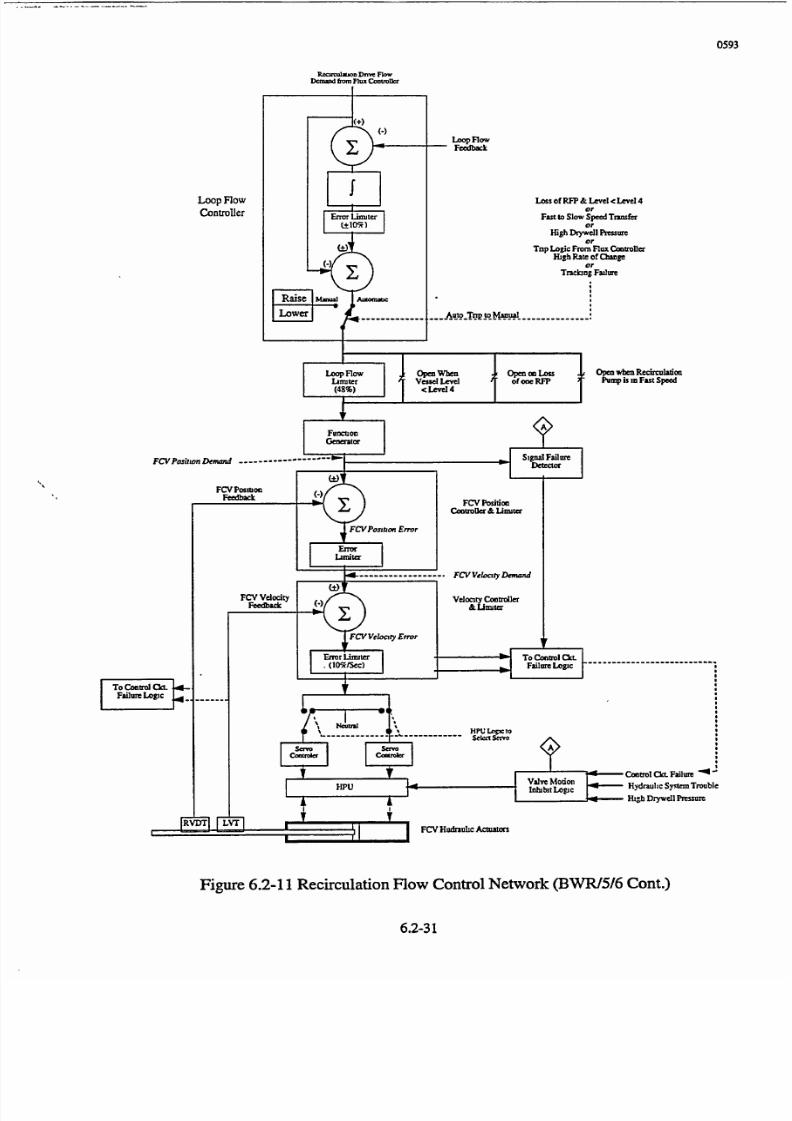
6.2.4.3 Recirculation Flow Control "The recirculatiori flow control system, Figure
6.2-10 and 6.2-11, is capable of varying recirculation flow over a range of 35 to 100% with the
recirculation pumps in fast speed or 30 to 40% inslow speed. The 'major components of therecirculation flow control system include:
* Master Controller* Neutron Flux Controller* Flow Controller Operational Limiter Hydraulic Power Unit Valve Actuator
Master Controller
The master controller provide a means of controlling both recirculation flow control valvesfrom a single controller. Controller operation isaccomplished in manual or automatic. When in themanual mode, a power demand signal is manuallyestablished by the operator with a slide switch onthe front of the controller. In automatic mode of operation the'controller accepts a load demandsignal from the Electro-Hydraulic Control SystemThis*signal is then processed throughout
theremaining RFC System circuitry to adjustrecirculation flow and hence reactor power tobalance the load'demand. The normal mode of operation on the Master Controller is MANUALmode.
Neutron Flux Controller
The neutron flux controller provides a secondmeans of controlling both recirculation flow c6ntrolvalves from a single controller. In addition, it also
provides a stabilizing effect on plant operation byvirtue of its power feedback signal. When inmanual mode, a flow demand signal is establishedby the olerator. In automatic mode of operationthe controller receives a neutron flux demand signalfrom the master controller which is compared to thereference APRM signal. These two signals arecompared to produce an output signal in terms of a
u jjt. iecnmcai framing Cenler Rev 0497
".G.E. Technology Adv~anced Manual
uSICKt; Technica Training Cdenter 6.2-5 Rev 0497

7/30/2019 Ml 023010606
http://slidepdf.com/reader/full/ml-023010606 24/92
G.E. TechnoIoy Advanced Manual DifferenceslRecirc & RFCflow demand signal. The normal mode of
flow demand signal. The normal mode of operation for this controller is MANUAL.
Flow Controller
The loop flow controllers, one for each loop,provide a means of individually controlling the
flow control valves. These controllers can also be
operated in manual or automatic. In the automaticmode the controllers receive a flow demand signalfrom the flux controller and also a flow feedback from the flow element in its recirculation loop
suction piping. These two signals are comparedand produce an output signal in terms of a flowerror signal which is transmitted to its respectivehydraulic power unit. Normal mode of operationis automatic.
Operational Limiter
The flow controller output signal is processed
through a loop flow limiter. When the recirculation
pumps are in fast speed the flow limiter limits thesignal to a maximum of 48% loop flow (38% FCVposition) in the event there is a loss of one reactorfeed pump and level cannot be controlled above the
low level alarm point.
The purpose of the limiter is to reduce reactorpower to within the capacity of one reactor feedpump by closing the FCVs.
Hydraulic Power Unit
The hydraulic power unit is a self containedhydraulic oil system for each recirculation flow
control valve. The HPU receives an electric flowsignal from the flow controller and converts it into
a hydraulic oil pressure signal which then positionsthe FCV via the valve actuator. FCV positioncannot be changed without the HPU in operation.
6.2.4.4 Power/Flow Map
A tool used to monitor BWR performance is a
power/flow map (Figure 6.2-12). The power/flow
map is a plot of core thermal power (in percent of rated) versus core flow rate (also in percent of
rated) for various operating conditions. The
power/flow map contains information on expectedsystem performance and limits on the recirculationsystem for operation of the recirculation pumps, jetpumps, and flow control valve.
6.2-5 Summary
The Recirculation System evolved from a 5loop, with variable speed pumps, system for theBWRJ2 to an internal jet pump two loop system forBWRs 3 through 6. The BWR/3 and 4 utilize twovariable speed pumps and 20 internal jet pumps to
obtain the necessary core flow while minimizingthe vessel penetrations. BWRs 5 and 6 also have
two independent recirculation loops like the
BWR/3 and 4, but vary core flow by throttling
flow with a flow control valve.
USNRC Technical Training Center 6. Z-9 Rev 0497
G.E. Technolog~y Advanced Manual Differences/Recirc & RFC
Rev 0497USNRC Technical Training Center 6.2-9

7/30/2019 Ml 023010606
http://slidepdf.com/reader/full/ml-023010606 25/92
From
Instrumentation shown is typicalof all five loops. To APRM System
Figure 6.2-1 BWR/2 Recirculation System
6.2-11
0195
To Reactor
To
ShutdownCooling

7/30/2019 Ml 023010606
http://slidepdf.com/reader/full/ml-023010606 26/92
0497-6
MANUAL
BWR/2 ONLY
I I
-±{--T1I
SIMILIAR FOROTHER RECIRCULATION
LOOP(S)
Figure 6.2-2 RFC System (BWR/2,3 &4)
6.2-13
MANUAL

7/30/2019 Ml 023010606
http://slidepdf.com/reader/full/ml-023010606 27/92

7/30/2019 Ml 023010606
http://slidepdf.com/reader/full/ml-023010606 28/92
1294
TO'B'LOOPSPEED CONTROL
OPTIONALSE'I'NG
"YCONTACTSSHOW FOR FIELD
BREAKER CLOSED
HI-102% OF RATEDRECIRC PUMP SPEED
LO-45% SPEED(OPTIONAL SETTING)
- Open when Rx. water level Is <12,5'
Open when discharge
valve notfull
open.
Open when feedwater flowis <20%
Open with lossof Condensate,
Cond. Booster orFeed Pump
ERROR UMITINGNETWORK
FEEDBACK
4
CAM
Figure 6.2-4 Recirculation System Flow Control Network (BWR/3/4)
6.2-17

7/30/2019 Ml 023010606
http://slidepdf.com/reader/full/ml-023010606 29/92
0989
SI dC"
Figure 6.2-5 Recirculation Pump Motor Generator Start Sequence
6.2-19

7/30/2019 Ml 023010606
http://slidepdf.com/reader/full/ml-023010606 30/92

7/30/2019 Ml 023010606
http://slidepdf.com/reader/full/ml-023010606 31/92
CF)
0,
RWCU RWCUSYSTEM SYSTEM
Figure 6.2-7 Recirculation System (BWR/5 &6)

7/30/2019 Ml 023010606
http://slidepdf.com/reader/full/ml-023010606 32/92
Fast SpeedBreaker
CB I ' LFMG Set InputI1& ATWS Breaker
EOC - RPT "A"
& ATWS Breaker
""EOC-RPT"B"CB 4) &ATWS Breaker
CB 2
___ 600V 15 Hz
LFMG Set Output& ATWS Breaker Low'
GM Motor
240 V H 480V60 lz
Voltage
Regulator
Figure 6.2-8 Recirculation Pump Power Supplies
FrequencyGenerator
CB5
CB 3
RecirculationPump Motor
0No

7/30/2019 Ml 023010606
http://slidepdf.com/reader/full/ml-023010606 33/92
sOFLoop-to-LoopdOF IDome-Loop<100 FDome-Drain
To Fast Speed
Start Seq
0195Slow Speed Sequence nitiated (Seal in)
Figure 6.2-9 BWRP5 & 6 Slow Speed Start Sequence
6.2-27

7/30/2019 Ml 023010606
http://slidepdf.com/reader/full/ml-023010606 34/92
7/30/2019 Ml 023010606
http://slidepdf.com/reader/full/ml-023010606 35/92
0593
Recumvumo Dnw FlowDemed fum Flux Commwm
Open when RecirculationPump is in Fast Speed
Failure Loio
m Control CkL. FailureHPU Vinhibt Logic Hydraulic Sy.tem Trouble
High Drywell Pressure
FCV HudrulNrc Achtu orS/
Figure 6.2-11 Recirculation Flow Control Network (BWRI5/6 Cont.)
6.2-31

7/30/2019 Ml 023010606
http://slidepdf.com/reader/full/ml-023010606 36/92
11010 20 30 40 50 60 70 80 90 100
Percent Rated Core Flow
Figure 6.2-12 Power to Flow Map
ia,
120
110
100
90
80
I- 4
70
60
S40
30
20
10
0
0
7/30/2019 Ml 023010606
http://slidepdf.com/reader/full/ml-023010606 37/92

7/30/2019 Ml 023010606
http://slidepdf.com/reader/full/ml-023010606 38/92
G.E. Technoloay Advanced Manual Differences/Isolation & Inventory Control
6.3 REACTOR ISOLATION PRESSURE,and INVENTORY CONTROL,
FNLarning Objectives
1. Explain the purpose of the isolation condenser.
S2._ Explain the operations of an isolation con'denser.
3. Describe how the various BWR product lines
--dissipate decay heat.
4. . List the high pressure makeup water systemscapable of providing makeup water to thereactor vessel wh.en compensating forinventory loss via the pressure control
.method during vessel isolation.
623.1 Introduction
SThe discussion in this section deals with thevarious ways BWR product lines provide pressureand inventory control when isolated from theirheat sink.-In the event the reactor becomes isolated
returns the resultant condensate to a recirculationsystem suction line. By conserving inventory, thissystem eliminates ihe need for additional sources of
high pressure makeup. *'
All BWRs of other product lines use SRVsfor pressure control and thereactor core isolationcooling system to provide high pressure makeup
-. water to the reactor vessel. Additionally someBWR/4, all-BWR/5, and all BWR/6 product lineplants have another option available. The steam
. condensing mode of -the residual heat remnovalsystem can be used for reactor pressure control. In
this mode, reactor steam is reduced in pressuie. andthen condensed in the :RHR heat exchangers.Since the resultant condensate can be directed to theRCIC pump:suction, both systems can be used
together to. provide inventory_ conserving closedSloop 9peration. If the plant is -equipped with asystem called the high pressure coolant'injection(I•PCI) System it can also be used to ,control
pressure by aligning the system in the test mode to
the condensate storage tank (HPCI operation is
discussed in chapter 6.4).,
6.3.2 BWR/2 Product Line
Viull 1Lb Va~L biA, bV11I-- %UU1J11FV1v41L Vlk b)'bL-111 - .- - 11 1- II,
,-must control reactor vessel pressure and inventory. The BWR/2 product line incorporates bothAll BWR product lines have Safety Relief Valves - pressure and inventory, control into one system'(SRVs) to provide over'pressure protection, and isolation condenser system. The isolationhence control reactor pressure. In addition to .-condenser system is a standby, high pressure
SRVs, BWRs can control pressure with systems system that can remove fission product decay hea
like the isolation condenser, reactor core isolation, following a.reactor isolation and scram when thecooling system, highpressure coolant injecting ;main turbine condenser is not availableas a hea
system, and steam condensingmode of the residual - sink., During reactor isolation, the isolationheat removal system. All BWR facilities have a-- condenser will control the pressure rise and limi
means of providing high pressure makeup water to -,theloss of reactor water, thus avoiding overheating
- the reactor vessel to compensate for inventory loss the fuel-which could occur through opening of the
via the pressure control method.. safety relief valves -with no water makeup
-In the case-of the BWR/2 product line and* certain plants of the BWR/3 product line, both of
the isolation functions are carried out bY a single,* system called the isolation condenser system. The
isolation, condenser system draws off ýreactorsteam, condenses the steam in a condenser, and,-.,,
-The isolation condenser is not intended to be
activated fast enough to have any effect upon theinitial pressure spikes resulting from the variousoperational transients (turbine trip, main steam lineisolation,...). The system can be -activated
USNRC Technical Training 'Center '6.3-1 Rev 0497:' Rev Y0497"°,- USNRC Technical Training 'Center -- -1, -" 6.3-1
ý' G.E. Technolog~y, Advanced Manualp-
Differences/Isolation & Inventory Contro

7/30/2019 Ml 023010606
http://slidepdf.com/reader/full/ml-023010606 39/92
G..Tcnlg dacd aulDfeecsloato netr oto
manually or automatidally upon sustained highpressure. The isolation condenser has the capacityto remove reactor decay heat generated a fewseconds following a reactor scram from rated
power.
6.3.2.1 Isolation- Condenser
The isolation condenser, figuiie' 6.3-1,operates'by natural circulation. During systemoperation, steam flows from the reactbr,'condensesin the tubes of the isolation condenser,and returns(by gravity) to the reactor. The water head, Createdby' condensate flow to the reactor,' serves as thedriving force for the system.
The isolation condenser is approximately 55feet long,-12 feet in diameter, and holds approximately 29,000 gallons of water atfnorinal level.Two tube bundles are immersed in Water, onebundle at each end of the condenser. The shell sideof the condenser vents to atmosphere. Baffles areinstalled in the shell above the tube bundles toprevent the boiling action fr6m drivifig shell waterout through the shell vents.
The steam inlet valves are normally open sothat the tube bundles are at reactor pressure evenwhen in standby. The tube side of the isolationcondenser is vented to the main steam line duringnormal reactor operation. A suitained high rea'ctor
pressure automatically puts the isolation condensersystem in operation. An automatic initiation willsignal the'dc motor operated valve on thecondensaie return line to open and vent valves tothe maihn steam line to close. Steam then flows,under reactor pressure, to the isolation'condenrser.The steam is routed to both condenser tube bundles
where itf is condensed by the cooler wvater in theshell side of the condenser. To obtain the desiredflow of condensate from the isolation condenser tothe reactor vessel, the normally closed condensatereturni ,valve can be throitled by the operator in the
control room.
During operation, the water on the shell side
of the condenser will boil off and vent steam to theatmosphere. Two radiation monitors are providedon the shell side vent so that in the event of excessive radiation levels, the control room
operator will be alerted and can take necessarycorrective actions.
Following a reactor isolation and scram, theenergy added to the coolant'will cause reactorpressure to increase and may initiate the' isolationcondenser. The capacity of this system isequivalýnt to the decay heat rate generation 5minutes following the scram and isolation' With nomakeup water, the volume of water stored in theisolation condenser will be depleted in 1 hour and
30 minutes. This allows sufficient time to initiatemakeup water flow to the shell side of thecondenser.
Makeup water is normally added from thedemineralized water makeup system to avoidconcentrating radioactive matter resulting' fromnormal water evaporation that occurs in standbymode. Additional water is available from thecondensate and fire protection systems.
6.3.3 BWR/3 Product Lines
The BWR/3 product line plants are dividedeienly as to the number that utilize the isolationcondenser or the newer reactor core isoiationcooling system. The previous isolation condenserdiscussion also applies to the BWRI3 product linesthat have isolati6n condensers. Therefore, it willnot be covered again in this section.
6.3.3.1 Reactor Core Isolation Cooling
The Reactor Core Isolation Cooling (RCIC)
system , figure 6.3-2, consists of a steam turbinedriven pump capable of delivering water to thereactor vessel at operating conditions. Operation of the RCIC system is fully automatic, or manual by
operator selection.' The system will start automatically upon receipt of an initiation signal from thereactor vessel low water level sensors. The systemwill shutdown automatically upon recovery of
USNRCTechnicalTrainingCenterbJ-Z Rev 0497
G.E. Technology Advanced Manuial Differ~ences/Isolation & Inventory Control
USNRC Technical Training CenterRev 04976.3-2

7/30/2019 Ml 023010606
http://slidepdf.com/reader/full/ml-023010606 40/92
G..Tcnlg dacd aulDfeecsloato netr oto
reactor water level to the high water level set pointor upon indication of certain RCIC malfunctionswhich will trip the turbine.
Water supply to the system is normally fromthe condensate storage tank through a motor
operated suction valve and check valve. This RCIC
., suction line is maintained flooded in the standby
-condition to,keep the RCIC pump continuously.primed. An alternate source of water for the RCICsystem is provided by the suppression pool. This
-source of water would be used if the water level in
the storage tank(s) were low or the water level in
suppression pool is too high.
The turbine is driven by steam produced in
the reactor vessel and exhausts to the suppression
pool, under water. The turbine driven pump
supplies makeup water from the condensate storagetank, or alternately from the suppression pool, tothe reactor vessel via the feedwater piping.
Additional discharge flow paths are provided to
allow recirculation to the condensate storage tank
for system testing and to provide pump minimumflow to the suppression pool for pump protection.Sufficient capacity is provided to prevent reactorvessel level from decreasing below the top of the
core. The system flow rate is approximately equalto the reactor water boil off rate 15 minutes
following a reactor scram and isolation.
6.3.4 BWR/4 Product Lines
The BWR/4 product lines all have a RCICsystem to provide core cooling makeup water to thereactor vessel under isolation conditions. Later
BWR/4 plant designs utilize the RHR system as an
additional mode of isolation pressure and reactor
water inventory control.
Following isolation of the reactor from its
primary heat sink, the residual heat removal system
steam condensing mode, figure 6.3-3, is used in
conjunction with the RCIC system to remove decay
heat and minimize makeup water requirements.Decay heat raises the temperature and pressure of
the coolant until the safety relief valves open. As-the SRVs continue to remove decay heat in the
*form of steam, the water level in the reactor 'vesselwould decrease. The RCIC system would be
started either manually or automatically to providemakeup water to the vessel under this condition.
Shortly after the RCIC system is started, the steam
condensing mode can be lined up for operation.
To begin steam condensing operation, theheat exchanger shell side inlet and 6utletf valves areclosed. The service water system supplying the
heat exchangers is placed in operation to provide
cooling water flow.
The heat exchangers le' el controller is placed
in the manual mode and the level control valve isopened about 10%. The heat exchanger vent
valves are throttled open to allow noncondensible
,-gases -to vent to the suppression pool. With thepressure controller set at zero, the steam inlet valveis slowly opened. The pressure set point is slowly
-increased to 50 psig, allowing steam pressure to
-oforce waterfrom the, heat exchanger.-to the
suppression pool through 'a motor operated
isolation valve.' As level .decreases,-the level
control valve is adjusted to maintain desired level.
The pressure controller is placed in the automaticmode and pressure is raised to 200 psig.
When RHR system outlet conductivity
indicates adequate purity, the flow of condensate is
shifted from the suppression pool to the RCIC
pump suction. The level control valve is controlled
by the lower of two signals, heat exchanger levelor RCIC pump pressure. The suction pressure
controller is normally set at 45 psig to prevent over
pressurizing the RCIC pump suction piping. Level
is adjusted to remove the desired amount of decayheat, either to maintain the plant in hot standby orto begin a plant cooldown. As heat exchanger level
is decreased, more surface area of the tubes is
exposed, thus allowing steam to condense faster.
The RCIC pump flow controller is adjusted to
equal the rate of condensation, thus reactor waterlevel remains nearly constant. The higher pressure
- Rev 114Y7
USNRC Technical Training Center3 - --6.3-3
.•G.E. Technology Advanced ManualI ;
Differences/Isolation & Inventory Control
S.. .Rev- 0497

7/30/2019 Ml 023010606
http://slidepdf.com/reader/full/ml-023010606 41/92
G.E. Tcchnolo2y Advanced Manual Differencesllsolation & Inventory Control
in the RCIC System'ýsuction piping closes thecheck valve in the CST suction line, ensuring thatcondensate is pumped from the RHR heat
exchangers.
The flow path for the steam condensingmode is as follows: reactor steam passes throughthe combined RCIC turbine/RHR heat exchangersteam line to the RHR heat exchanger(s);
condensate from tlie RHR heat exchanger(s) isforced (by heat exchanger pressure) to'the su6tionof the RCIC pump; condensate is pumped by theRCIC System to the reactor vessel via thefeedwater line. This mode must be manuallyaligned by the control room operator.
6.3.5
6.3.6 Summary
All BWRs provide pressure and inventorycontrol for the reactor vessel. All BWRs are
equipped: with SRVs to provide over pressureprotection. In addition to SRVs Isolation
condensers are employed for pressure and
inventory control for BWR/2s and some 3s.react6r core isolation cooling systems are used forBWR/4, 5s, 6s and some 3s for pressure andinventory control when the reactor is isolated. Inaddition to the reactor core isolation coolingsystem, some-BWR/4s, 5s and 6s are equipped
with a steam condensing mode of the residual heat
removal system for pressure control.
BWR/5 and BWR/6 ProductLines
The BWR/5 and BWR/6 product lines
provide reactor vessel pressure and water levelcontrol during isolated conditions with the RCICsystem and steam condensing mode of the residualheat removal system. The basic RCIC remainsunchanged except four changes in turbine glandsealing and pump discharge. Some BWR/6s weredesigned to have the RCIC system discharge intothe reactor vessel head for better pressure control.
USNRC Technical Training Center
G.E. Technology Advanced Manual Differences/Isolation & Inventory Control
6.3-4 Rev 0497
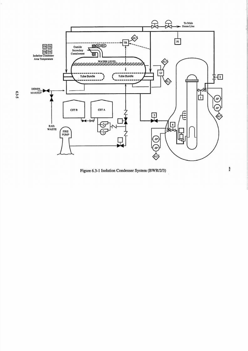
7/30/2019 Ml 023010606
http://slidepdf.com/reader/full/ml-023010606 42/92
0ý
Figure 6.3-1 Isolation Condenser System (BWR/2/3)

7/30/2019 Ml 023010606
http://slidepdf.com/reader/full/ml-023010606 43/92
4
TO MAIN !TURBINE
SAFETY/RELIEF 1VALVES !
I
I
TURBINE SUPPLYEXHAUST LINE SHUTOFF
44-VALVE
ITRIPTHROTTLVALVE
ETURBINE
AO M
Figure 6.3-2 RClC System (BWR/3/4)
6.3-7
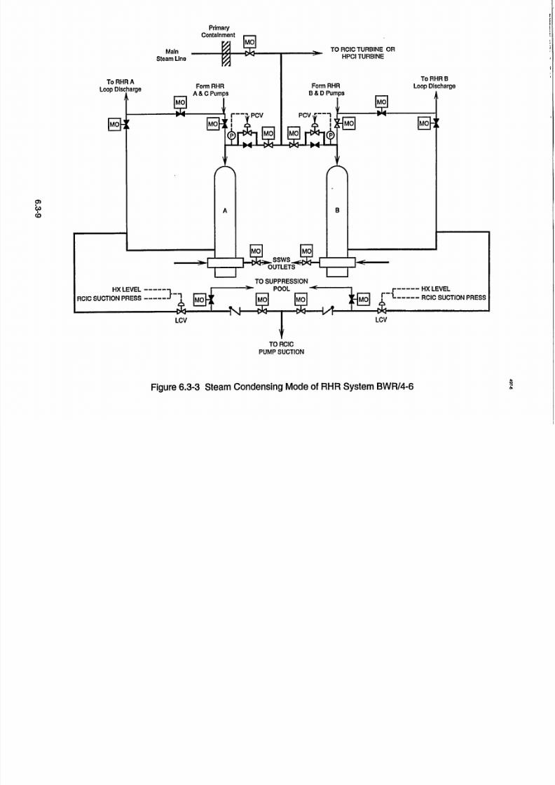
7/30/2019 Ml 023010606
http://slidepdf.com/reader/full/ml-023010606 44/92
TO RCICPUMP SUCTION
Figure 6.3-3 Steam Condensing Mode of RHR System BWR/4-6
PrimaryContainment
0)
(0
A.-4

7/30/2019 Ml 023010606
http://slidepdf.com/reader/full/ml-023010606 45/92
CONDENSATEAND FEEDWAT
/ i STEAM
-- -- - - - - - - - ,- .. . " ,.,.. . ,.
,... SYSTEM
r• (Steam Condensing Mode)
Steam SupplyM Shutoff Valve
"EXHAUS M Trip Throttle
M Valve
-L WATER LEG A.1 fnvpmnr
Figure 6.3-4 RCIC System (BWR/5/6)

7/30/2019 Ml 023010606
http://slidepdf.com/reader/full/ml-023010606 46/92
G.E. Technology Advanced Manual Differences/ECCSs
Table of Contents
6.4 EMERGENCY CORE COOLING SYSTEMS ......................................... 1
6A .1 Introduction .............................................................. 1
6.4.2 BWR/2 ECCSs ........................................................... 16A.2.1 Automatic Depressurization System ................................. 1
6.4.2.2 Core Spray System ............................................... 1
6.4.3 BW R/3 ECCSs ........................................................... 2
6.4.3.1 High Pressure Coolant Injection System .............................. 2
6.4.3.2 Core Spray System ............................................... 3
6.4.3.3 Low Pressure Coolant Injection (LPCI) System ....................... 3
6.4A BWR/4 ECCSs ........................................................... 5
6.4.4.1 Residual Heat Removal System (LPCI Mode) .......................... 5
6.4.5 BW R/5 & BW R .......................................................... 5
6.4.5.1 High Pressure Core Spray System ................................... 5
6.4.5.2 Low Pressure Core Spray System .................................... 5
6.4.5.3 LPCI Mode of RHR System ........................................ 6
6.4.6 ECCS Suction Strainers .................................................... 6
6.4.6.1 Large Capacity Strainers ........................................... 8
6.4.6.2 Core Damage Frequency Estimates .................................. 9
6.4.7 Summary ............................................................... 11
List of Figures6.4.1 BWR/2 Core Spray System ................................................. 13
6.4.2 Typical ECCSs for BWR/3 & BWR/4 ........................................ 15
6.4.3 High Pressure Coolant Injection System ....................................... 176.4.4 Core Spray System BWR/3 & BWR/4 ........................................ 19
6.4.5 LPCI System BWR/3 & BWR/4 ............................................. 21
6.4.6 LPCI Loop Selection Logic ................................................. 23
6.4.7 Residual Heat Removal System ............................................. 25
6.4.8 Typical ECCSs for BWR/5 & BWR/6 ........................................ 27
6.4.9 ECCS Divisional Assignment ............................................... 29
6.4.10 ECCS Integrated Performance .............................................. 31
6.4.11 Strainer Assembly ........................................................ 33
6.4.12 Stacked Disc Strainer ..................................................... 35
6.4.13 T-Suction Strainer ........................................................ 37
6.4.14 Mark III Containment Strainer .............................................. 396.4.15 RCIC Suction Mark M11 Containment ......................................... 41
6.4.16 Simplified Event Tree for Large LOCA ....................................... 43
USNRC Technical Training Center 6.4-i -.,- " . Rev 0199

7/30/2019 Ml 023010606
http://slidepdf.com/reader/full/ml-023010606 47/92
G.E. TechnoIo2y Advanced Manual DifferenceslECCSs
USNRC Technical Training Center 6.4-i Rev 0199USNRC Technical Training Center 6.4-i
G.E. Technolog~y Advanced Manual Differences/ECCSs
Rev 0199

7/30/2019 Ml 023010606
http://slidepdf.com/reader/full/ml-023010606 48/92
G.E. Technology Advanced Manual DifferenceslECCSs6.4 EMERGENCY CORE CO6.4 EMERGENCY- CORE CO(
SYSTEMS
Learning Objectives:
1. List the high and low pressure EmCore Cooling Systems for the
product lines and explain the pur
each.
-,2.: List the advantages the BWR/5 and
"ECCSshavre over the BWR/3 and mo-. -BR4product lihe ECCSs.
3. Explain how' the various types of "providecore cooling.
4. List the advantages between the old/
ECCS suction strainers.
5. List the four identified strainer resoloptions.
"6. Explain why a BWR/4 should havecore da'ma'ge frequency than a BWR
-BWRI6.
6.4.1 Introduction
- The Emergency Core Cooling(ECCS) package provided by a particularline is dependent on the vintage of the plant
:regulations during that peri6d of time. In
there are high pressure'and low pressure
The'•- Automatic Depressurization Syis
functionally the same for all facilities.'
The purpose of the'ECCSs. in conj
with the containment systems, is to *lirelease of radioactive materials to ihe en~ir
following a loss of coolant accident so,resulting radiation' exposures -are wi
guideline values of 10 CFR 100.
OLING 6.4.2 BWR/2 ECCSs
% The BWR/2 product line ECCSs consists of
-the Isolati6n: Condenser, System; Automatic
- Depressurization System,. and the Core Spray
lrgenicy System. 'The' three ECCSs operate in variousvarious combinations to -"maintain peak ccladding
pose of 'termiperature below 2200'F and within the limits
specified in' 10 CFR' 50.46 for any size break
LOCA. They must also meet single failure criteria.BWR/6 The Isolation CondenseroSystemris a passive high
ist of the 'pressure system whiich consists of two independentnatural circulatiori"'heat -'exchangers, that are
aiufmaticallyiiniiated by high reactor 1rie.sure or
ECCSs l16w-low (level-2) water level. Isolation Condenseroperation is' -discussed in': chapter 6.3.-: The
Feedwater System can supply an adequate amount /new of cooling water to replace that lost through an
"extended range of pipe break sizes, providingnormal 'stti0on power, and/or offsie p'o-ver is
ution available.
6.4.2.1 Autom~itic Deiressurization Systema higherSor The Automatic-Depressurization System
(ADS) consists of five''automatically, activated
relief valves that depressurize' the reactor vessel
during a small break LOCA to permit the low"pressure.CoreSpray System to inject water on top
System of the core.pr6duct .
tand the The five ADS valves are actuated by lowall cases low-low (level- 1)reactor water level, high drywell
ECCSs. ' pressure, indication that acore spray booster pump
tem. is has'started, and a 120 second time delay. Only
four. of the 'five SRVs are required to achieve"ýdepressurizationr in the allowable time period.'
jtiction
fiiit' the '6.4.2.2 Core Spray Systemrtnmentthat the myTheCoreSpraySstem provides an adequate
bin the supply, of cooling ',water independexit of the
"FeedwateiSysterfiand can be pow•eredfrom the
emergency power system.
USNRCTechnicalTrainingCenter- 6.4-1Rev 0199
ý--G.E.-Technolo-i' Advanced Manual Differences/ECCSs
SUSNRC Technical Training Center -- 6.4-1 .• -' , Rev 0199

7/30/2019 Ml 023010606
http://slidepdf.com/reader/full/ml-023010606 49/92
G.E. Technology Advanced Manual Differences/ECCSs
The Core Spray System (Figure 6.4-.1) is alow pressure system which supplies cooling waterafter reactor pressure is reduced to 285 psig. Thissystem will prevent the reactor from overheatingfollowing intermediate or, large breaks. To
accommodate some intermediate to small pipebreaks when feedwater is not available, the ADSwill depressurizes the reactor thus permitting the
Core Spray System to provide core cooling.
The Core Spray System c6nsists of twoidentical loops. Each loop contains two mainpumps, two booster pumps, two sets of parallelisolation valves one set inside and the other outsidethe drywell, a spray sparger, and associated piping,instrumentation and controls. Each pump is rated at
3400 gpm full flow capacity.
Water is supplied to the system from the
suppression pool. Also, the Fire Protection Systemis connected to each of the core spray loops toprovide a backup supply of water. Each loop hasa test recirculation line to the suppression pool forfull flow testing without discharging into the
reactor vessel. The piping up to the test valve iscarbon steel, designied for 400 psig and 3500F.From the injection isolation valves to the reactor
vessel, the piping is stainless steel designed for1250 psig and 5750F. A core spray-filling systemmaintains the Core Spray System full to precludeany danger of water hammer when the system goes
in operation.
The discharge from each of the main pumpsflows through a check valve to a common headerthat supplies water to the boostei pumps and abypass line around the booster pumps. The boosterpumps discharge piping contains motor operated
isolation valves outside the drywell and airoperated testable check valves inside the drywell.Flow from each loop is directed from the pumpsthr6dgh two parallel 'irormally closed motor6peiated valves, a single line at the containment
"penetiaiionr, two parallelcheck valves, one lockedopen manually operated valve and 'intothe sparger.
Both Core Spray Systems and their diesel
generators will automatically start upon thedetection of one high drywell pressure or one lowlow reactor vessel level condition. Theseconditions generally indicate a pipe break., Thesystem can also be manually initiated by the
control room operators.
6.4.3 BWR/3 ECCSs
The BWR/3 product linehigh pressure ECCSconsists of an ADS system and either a FeedwaterCoolant Injection (FWCI) System or a turbinedriven High Pressure Coolant Injection System,Figure 6.4-2. The low pressure ECCS consists of two Core Spray System loops and two LowPressure Coolant Injection loops (either as a
separate system or as a mode of the Residual HeatRemoval System).
6.4.3.1 High Pressure Coolant Injection
System
The High Pressure Coolant Injection System(HPCI) maintains adequate reactor vessel waterinventory for core cooling on small break LOCAs,assist in depressurization of the reactor vessel toallow the low pressure ECCSs to inject on
intermediate break LOCAs, and backs up, thefunction of the Isolation Condenser or ReactorCore Isolation Cooling System under reactorisolation conditions.
The HPCI system, Figure 6.4-3, is anindependent ECCS requiring no AC power, plantservice and instrument air, or external coolingwater systems to perform its purposes. The HPCIsystem consists of a turbine, turbine driven pumps,the normal auxiliary systems required for turbine
operation, and associated piping. andinstrumentation.
The HPCI system is normally aligned to
remove water from the condensate storag, tank andpump the water at high pressure to the reactorvessel via the feedwater piping. The suppressionpool is an alternate source of water with automatic
USNRC Technical Training Center 6.4-2 Rev 01996.4-2 Rev 0199
IG.E. Technology Advanced Manualv_ Difference~s/ECCSs
USNRC Technical Training Center

7/30/2019 Ml 023010606
http://slidepdf.com/reader/full/ml-023010606 50/92
G.E. TechnoIoy Advanced Manual Differences1ECCSs
selection on high suppression pool water level or The- Core Spray -Systei
low condensate storage tank water level. A test'- 'automatically to provide core cool
line permits functional testing of the system durinig of either high drywell'pressure oi
normal plant operation.- A minimum flow path to water level and low reactor pressi
the suppression pool is .provided for the HPCI
pump in the event the pump is operated with a -6.4.3.3, Low Pressure Coolantclosed discharge path. - (LPCI) System
High *pressureemergency core cooling for
"smalland intermediate'line breaks is provided by
the HPCI System.' During' such breaks,- reactor
-water level could drop to a level where the core is
not adequately cooled while the reactor remains at
or near rated pressure. With reactor pressure high,
the low pressure ECCSs would not be capable'of
supplying water to the reactor vessel. The HPCI
system can supply makeup water to -the reactorvessel from -above rated reactor pressures to a
pressur'e bel6w that of the low pressure ECCSs
.injection pressure.
System' initiation can be accomplished-by
automatic signals or manually by the control roomZ operator. •Receipt of either i reactor low-low water
-level or high drywell pressure will automatically
"-startthe HPCI system.
6.4.3.2 Core Spray System
'The Core Spray System (Figure 6.4-4) puwater from the suppression pool into the rez
vessel via spray nozzles located on indepenring spargers located within the core shroud al
S thefuel assemblies. 'The nozzles are position(
provide auniform distribution of coolant to the
assemblies.
The Core Spray' System 'consists of
independent loops. Each loop contains a [ioperated injection stop valve outside the dry
and a testable' check valve plus a manual stop v
within the drywell: Each loop also contains suc
isolation' ales', test line, minimum flow linea keep fill line.
m is initiateding upon receiptlow-low vessel
ire.
Injection
"The'LPCIsystem is a closed loop system of
piping, -pumps, and heat 'exchangefs that are
designed to remove post power operation energy
from the reactor under both operational and
accident conditions. The- LPCI systemaccomplishes this function in several but
-independent modes of operatio':;
"LPCIMode - The LPCI mode operates'inconjunction with the -PCI, ADS, and
"Core Spidy systems- to' restore, if
hecessary, the water level in the reactorvessel following a LOCA. ;
"Suppression Pool Cooling Mode - Thismode of the LPCI system is manually
* initiated following a LOCA to preventpool temperature from exceeding 170TF.
SContainment; Cooling Mode -The, .. containment cooling mode permits spray
mps cooling ofthe drywell and suppressionactor chamber to remove additional heat
dent -. energy from- the primary containment
bove following aLOCA. This is accomplished
-dto '- -' 'through the condensation of steam and
fuel "spray cooling of noncbndensibles.
The LPCI system (Figure 6.4-5) includes twotwo separate -circ'ulating loops. Each loop includes a
Lotor heat exchanger,,'two- main- system pumps inwell parallel, and associated piping. The two loops are
'alve -normally"cross-connected "by -a single header,
:tion making it possible to supply either LPCI loop from
and ' the pumps in the other loop.-I . -'
USNRC Technical Training Center 6.4-3 - ' ' KeVUIYYUSNRC Technical Training Center S: ' ",• *Rev 01"996.A-
SG.E. Technolozvy Advanced Manual "'." -Differences/ECCSs

7/30/2019 Ml 023010606
http://slidepdf.com/reader/full/ml-023010606 51/92

7/30/2019 Ml 023010606
http://slidepdf.com/reader/full/ml-023010606 52/92
G.E. Technoloaiy Advanced Manual Differeiice /ECCSs
6.4.4 BWR/4 ECCSs
-.. ThIe BWR/4 product line highpressure EC-"consists of a HPCI system:and an ADS. The
-'pressureECCSS consists of a Core Spray Sys
":and i Residuial Heat Removal Systemw',ith a L"mode.-The high presstire ECCSs are the sam
* the BWR/3 product'line with the exception ol
"number -of 2SVs - used for autom
deiessuzriiation. The Core Spray System issame as a BWR/3 ekcept for the initiation'sig
afid nuinber 6f pumps per loop. -initiation sig- Uised for the low pres'sure ECCSs isý high dry
'"pressure or low-low-low (level-1) vessel %
"-leel. The LPCI Miode of the'Residual Heat
"-moval System was divided into two separate
independent loops for most of the BWR/4s dt"their higherpower dersity cojes and the nee
"meetthe requirementi of 10 CFR'50.46.
6.4.4.1 Residual Heat Removal System
(LPCI Mode)
"I. . The RHR System, Figure 6A4-7 is a multi- pose system which has five operatioial mo
each with a specific purpose. The RHR sysconsists of two separate piping loops, design
'-system I and system 2. Each loop containspumps, two heat exchangers and associated pi4
valves, and instrumentation.
6.4.5 BWR/5 & BWR/6
CSs - The BWR/5 and BWR/6 product line ECCSs
low consists of a High Pressure Core Spray System,
;tem' 'ADS, Low Pressure Core Spray System, ahd LPCI
PCI- *. mode of the RHR System, Figures 6.4-8,,9 and 10.[6 as t--Due to'the unreliability of the HPCI systems 6nFthe earlier BWRs, the BWR/5, and 6 were designedatic with a motor driven high pressure make up system.
nals - 6.4.5.1' High Pressure Core SpyraySystemnals -
well -The High Pressure Core Spray (HPCS) System!ater 'provides high pressure emergency core cooling for
Re- - small, intermediate, and large'line breaks. Theand " HPCS System,' shown in Figure 6.4-3 is a single
ie to loop system and consists of a suction shutoff valve,d to one motor drive pump, discharge -check valve,
motor operated injection valve, minimum flowvalve, full flow test valve to the suppression pool,
two high pressure flow test valves to the conden-sate storage tank, discharge sl~argr and associatedpiping and instrumentation. HPCS takes-suction
pur- from'the condensate storage tank or suppressiondes, pool and pumps the water into a sparger located on
,tem" the upper core shroud. Spiay nozzles mounted onated - the sparger are directed at the top of the fuel assem
two blies to remove decay'heat following a loss of iing, coolant accident (LOCA). The suppression pool is
-- the alternate source of Water for the HPCS system.
- The low pressure coolafit ,injection (LPCI) HPCS -initiates automatically on 'either highmode is the dominate mode and normal valve 'pressure 'inthe drywell or-low water level in the
"lineup configuration of the RHR'system. The- reaicor vessel (level-2). In the event HPCS is any
LPCI mode operates automatically to restore anid- r-hode otherthan standby and an automatic initia
maintain, if necessary, the fuel clad temperature tion signal is riceived; all valves realign for thebelow'22000 F. During LPCI operation, the RHR- injeciion mode of operati6n. Normal power for the
- pumps take water from the suppression pool and HPCS system power is provided from the Standby
discharge to the reactor vessel via their respective, '-P6wei System' division 3 diesel generator.recirculation' system discharge piping. - . .- "-• -
• - " . .. '6.4-5.2 ',Low Pressuire Core Spray System
The'exceptiofi to the above mode desdriptioniis -- . - :
that two' of the BWR/4 plants'hae four separate The low pressure co
and indipe•ndent LPCI loops which discharge -"loop system -and coAs
-.- - diiectly int6 the reactor vessel shroud. valve, one motor driveivalve, motor- operated i
re spray system is a single
ists of a s6ction shutof
i pump, discharge check
njection valve, minimum
USNRCTechnicalTrainingCenter6.4-5Rev 0199
S....'Rev 0199
"G.E. Technology-Advanced Manual Diffiirefcis/ECCSs
USNRC Technical Training Center 6.4-5

7/30/2019 Ml 023010606
http://slidepdf.com/reader/full/ml-023010606 53/92
G.E. Technolotrv Advanced ManualDiernslC s
flow valve, full flow test valve to the suppression
pool, discharge sparger and associated piping and
instrumentation.- LPCS takes suction from the
suppression pool and discharges the water through
the core spray sparger ring directly, on top of the
fuel assemblies. This provides' core cooling byremoving the decay heat generated from the fuel
bundles following a postulated. loss of coolant
accident.
The LPCS, along with other ECCSs, is automati
cally initiated by either high pressure in the drywell
or a reactor water level-1. -The motor operated
valves automatically lineup for emergency mode of
operation upon asystem initiation signal regardless
of the alignment unless the system' has been re
moved from service formaintenance by closing themotor operated suction valve.
6.4.5.3 LPCI Mode of RHR System
The RHR System is a multipurpose systemwhich has five operational modes, each with a
specific purpose. The RHR system consists of
three separate piping loops, designated A, B, and
C. Loops A and B each have a pump and two heat
exchangers. Loop C is used exclusively for LPCI
mode and is not equipped with a heat exchanger.
The low pressure coolant injection (LPCI)
mode is the dominate mode and normal valve
lineup configuration of the RHR, system. The
LPCI mode operates automatically to restore and
maintain, if necessary, the fuel clad temperaturebelow 22000F. During LPCI operation, the RHR
pumps take water from the suppression pool and
discharge to the reactor vessel inside the core
shroud via their own individual penetrations. The
LPCI mode initiates automatically on either highpressure in the drywell or reactor vessel water level
low (level-i). In the event the RHR system is any
mode other than standby and shutdown cooling and
an automatic initiation signal is received, allvalves
realign for the LPCI injection mode of operation.
6.4.6 ECCS Suction Str'aine-rs
In 1979,. the NRC established- USI A-43,
"Containment Emergency Sump Performance," to
study safety issues related to the ability of both
PWRs and BWRs to recirculate water back to thereactor core, following a postulated LOCA. The
NRC staff's resolution of USI A-43 regarding the
potential loss of post-LOCA recirculation capabil
ity due to intake blockage from dislodged insulation debris was transmitted to the industry in
Generic Letter 85-22."Potential for Loss of Post
LOCA Reciiculation Capability Due to Insulation
Debris -Blockage," on December 3, 1985. In
addition, the NRC staff recommended that Regula
tory Guide 1.82, Revision 1, "Water Sources for
Long-Term Recirculation Cooling Following aLoss-of-Coolant Accident," be used as a guideline
for 10 CFR 50.59 reviews dealing with the change
out and/or modification of thermal insulationinstalled in reactor coolant system piping and on its
components.
On July 28,1992, a spurious opening of a safety
valve at a Swedish BWR, resulted in the clogging
of twO ECCS pump suction strainers. During the
resiart, activities, steam was released into the
containment from a rupture disk on a'safety relief valve that had been inadvertently left open. The
release of steam dislodged mineral wool insulation,
pieces of which were subsequently transported by
the steam and water into the wetwell. Within one
hour, the fibrous debris clogged the ECCS inlet
strainers. This type of strainer clogging had been
previously considered as a possibility, but it was
believed that at least ten hours would have to
elapse before clogging would occur.
The regulatory authorities of Sweden anid othernorthern and central European countries viewed the
incident as a precursor to potential loss of ECCS
cooling due to LOCA-generated debris and initi
ated a safety reanalysis effort, coupled with experi
ments directed at establishing the following:
* the amount of insulation destroyed by steam
jet created by pipe break, valve opeiining, etc.;
USNRC Technical Training Center 6.4-6 ±Cev UIYY
USNRC Technical Training Center
Differences/ECCSs
Rev 01996.4-6

7/30/2019 Ml 023010606
http://slidepdf.com/reader/full/ml-023010606 54/92
-GE Technoloov Advanced ManualDieecs/C s
. the composition of the resulting debris;
* the amount of debris transported to the suppression pool;
* the extent of insulation debris buildup on
strainers; and
* the resultant increase in pressure drop acrossthe strainer under the postulated conditions.
Results of the European experiments were corn
pared with results obtained for resolution of ":
USI A-43. The comparison showed that prior. -correlations derived.for debris head loss, when
compared to Swedish experimental data and event,
underestimated pressure losses.
, . Instances of clogging of ECCS pump strainers
have also occurred at U.S. plants, including two
events at Perry Nuclear Plant.' The first eventresulted in deformation of RHR pump suction
strainers due to buildup of operational debris. This.
buildup caused an excessive differential pressure"acrossthe strainers. The second Perry event alsoinvolved the deposition of debris on the RHR"
pump suction strainers. The debris consisted of
glass fibers that had been inadvertently dropped
into the suppression pool from temporary drywell
* cooling filters; corrosion products and other materials filtered fromthe pool water by glass fibers
adhering to the surface of the strainer. This phe-nomenon is referred to as "filtering" and had not
been evaluated previouslyby the staff and industry.
Based on the new data, the NRC issued NRC
, . Bulletin 93-02 on May 11, 1993, which requested.that boih PWR and BWR licensees: -'
identify fibrous air filters and other temporary
sources of fibrous material in containment not
RHR suction strainer. At Quad Cities Station, Unit
1, on July 14,1994; the remains of a plastic bag
were found shredded and caught within the anti
cavitation trim of an RHR test return valve. Subse
quent to that event at Quad Cities, Unit 1, the
licensee observed reduced flow-from the C RHRpump upon .further. investigation, found a 10-cm
(4in.) diameter wire brush wheel and a piece of
metal wrapped aiound a vane of the pump.
On October 4, 1995, the NRC issued IN 95-47,
"Unexpected Opening of a Safety/Relief Valve and"-ComplicationsInvolving Suppression Pool Cooling
Strainer Blockage," Which discussed an-event on
-September 11, 1995, at the Limerick Generating
Station Unit 1, during which a safety/relief valve
,discharged to the suppression pool. The operatorsstarted an RHR.pump in the suppression pool
cooling mode. 'After 30 minutes, fluctuating motor
current and flow were observed. - Subsequent
inspection of the strainers found them covered with
"t'mat" of fibrous materialand sludge (corrosion"products). The licensee removed approximately
635 kg (1400 lb) of debris from the Unit 1lpool. A
similar amount of debris had been removed earlier
from the Unit 2 pool.
In BWRs that have'carbon steel components,corrosioh product particulate can be removed from
suppression pools, but ,will be regenerated, over
time, at a rate of 10-100 kg/year. -Inaddition, there
are numerous sources of fibers in a BWR Drywell.
Thermal insulation on pipe and equipment is an
obvious sourcebut there are many others, such as
protective clothing, welding fabric, fire protection
materials and even human hair.
designed to withstand a LOCA, and
take action to remove the material and ensure . Recent studies have consistently shown that
the functional capability of the ECCS. , ,:,-very small quantities of fibrous material (0.1 m3)S. . .- .. : combined with 100 kg or so of particulate, enough
On August 12, 1994, the NRC issued IN 94-57,.: to bring about RHR -pump cavitation when col
"Debris in Containment and the iResidual Heat lected oni small passive strainers like those found in
"RemovalSystem," Which alerted operating reactor - many of the world's BWR suppression pools.
licensees to additional instances of degradation of
ECCS components because of debris. At River Removing all sources of fibrous material from
Bend Station, the licensee found a plastic bag on an -apool is realistic and achievable. Guaranteeing that
USNRC Technical Training Center 6.4.7 KCVUIYY'-: 6.4- 1-ý ev 19
. Differences/ECCSs
"IUSNRCTechnical Training Center

7/30/2019 Ml 023010606
http://slidepdf.com/reader/full/ml-023010606 55/92
G.E.Techolov AdancdMaualDifferenceslECCSsall fibres have been removed from the drywell isnot realistic, and even if there are just a few fibres
the ECCS stainers can easily become blocked.
Based on the new data, the NRC issued NRC
Bulletin 95-02 on October 17, 1995, which discussed the Limerick event and requested the BWRaddressees review the operability of their ECCS
pumps and other pumps that draw suction from thesuppression pool while performing their safety
function.
NUREG/CR-6224 was issued October of 1995,
Parametric Study of the Potential for BWR ECCS
Strainer Blockage Due to LOCA Generated Debris.
On May 6, 1996, the NRC issued Bulletin 9603, ."Potential Plugging of Emergency Core Cooling Suction Strainers by Debris in Boiling-WaterReactors," which- requested actions by BWRaddressees to resolve the issue of BWR strainer
blockage because of excessive buildup of debris
from insulation, corrosion products, and otherparticulates, such as paint chips and concrete dust.The bulletin proposed four options for dealing withthis issue:1. Install large capacity passive strainers,
2. Install self-cleaning strainers, !3. Install a safety related backflush system that
relies on operator action to remove debris fromthe surface of the strainer to keep it from clog-
4.
ging, orPropose another approach that offers an equivalent level of assurance that the ECCS will beable to perform its safety function following a
LOCA.
The most practical and cost effective of the
mechanical solutions is to replace the existingsmall passive suction strainers with large passivestrainers' The modification represents the simplest, the most reliable, and the least disruptiveoption. The conclusion that large suction strainers are necessary is inescapable, especially when
it is recognized that only a thin layer of fibrousmaterial ; combined with a relatively small quan-
- tity of particulate, is required to bring aboutECCS pump cavitation at most of the world's
BWRs.
6.4.6.1 Large Capacity Strainers
Figures 6.4-11, 12, 13, and 14 illustrate the largecapacity passive strainers that have been or aregoing to be installed in the suppression pool.
The new passive strainer, Figure 6.4-11, beinginstalled at BWRs, in all three types of containments, increases the surface area from
approximately 9 ft2 to 108 ft2. The strainers measure approximately three and one half feet inheight and five feet in diameter. The uppermost
stacked disc measures two inches in thickness andcontains perforations on both surfaces. The remaining thirteen discs are one inch in thicknesswith perforations on both surfaces.. The centersection is truncated to provide a mounting platformfor the stacked disc and provide additional surfacearea. The stacked disc sections are held in place byvertical stiffener bars spaced at even intervalg.
Figure 6.4-12 represents the passive strainersbeing installed in some Mark I containments that
have an ECCS suction ring header that is locatedbelow the suppression chamber. Dresden installedthe strainer, illustrated in figure 6.4-12, that consists of 16 evenly spaced double faced stackeddiscs. The strainer measures approximately 5 feetin length and 32 inches in diameter. This type of strainer has asurface area of 118 f-0. In addition to
the stacked disc strainers, stiffeners are located 720
apart to provide rigidity to the strainer assembly.
Figure 6.4-13 represents the passive strainers
being installed at Monticello's Mark I containmentthat have an ECCS suction ring header locatedbelow the suppression chamber. This type of strainer has a surface area similar to the other styles
being installed in the Mark I containments, approximately 100 fe.
USNRC Technical Training Center 6.4-8 Rev 0199
G.E. Technology Advanced Manual Differences/ECCSs
Rev 0199- USNRC Technical Training Center 6.4-8

7/30/2019 Ml 023010606
http://slidepdf.com/reader/full/ml-023010606 56/92
- G.E. Techno1oy Advanced Manual DifferenceslEGCSs"-Figure 6.4-14 represents the -passive ktrainers
being installed in most Mark Mll containments. This
-is the largest of the passive suction strainers being
"installed. The 'strainer completely encircles the
drywell within the suppression pool. The strainer
has an outer radius of 62 feet and measures approximately 389 feet in circumference. The strainer is
supported by support legs that lift the strainer off of
the floor of the 'suppression pool approximately 6
"inches to expose square perforations in the bottom"of the strainer assembly. Low pressure ECCSs
take suction form the middle section while HighPressure Core Spray and the Reactor Core Isolation
-:Cooling System -remove 'water form the first
strainer cavity. To reach the center section water
must pass through the outer most strainer and then
--the rectangular center section'stiainer.
6.4.6.2 Core Damage Frequency Estimates
To gain additional insights into the potenitial
safety significance to ECCS NPSH loss, Core
Damage Frequency (CDF) estimates were calcu
lated for :flow blockage related BWR accident
sequencesin 'NUREG/CR-6224." 'The reference
" design used was a BWRI4 with a Mark I contain- Sequence's CD-3," CD-4; 'and CD-5 involve
"mnentdesign. The CDFestimates were'limited to successful operatorrecognition of strainer blockage
large break LOCA initiators having a diameter >6" coupled ývith'failure to use a back flush operation'(15.2 -cm)., The large break initiator was selected to restore the operability of the ECCS pumps. In
becaus'e smaller breaks were less likely to result in sequence CD-3, operators successfully established
loss of ECCS NPSH. Smaller break sizes could be an altemate injection source of cooling.,-Though
m'titigated by the HPCI and RCIC systems, both of - - torus coolifig cannot b; established because the
which take their initial supplie's from 'the conden- RHR' pump' NPSH remains lost, operators are
S:ates storage system. During the time one of these successful'in maintaining containment structure
systems is-dbeing 'used, the potential for strjiner: integrity by manually venting.'Even though subse
blockage would be eliminated -by pump 'suction 'quent overfill is postulated to lead to core damage,
form the condensate storage system. Onice conden- this situation was considered to be very-unlikely
"sate-storage system levels have dropped- suffi- 2-duriuig the 24-hourmitigating system mission time.
ciently to require'switchover to' the-suppression Consequently, the frequency established for CD-3'pool, rea~ctor decay heat levels would be substan- -'is negligible. ' ',
"tiallyreduced. If loss of NPSH occurs'following" -' .
switchover, the reduced decay heat levels would. In sequence CD-4, 'ai-alterhirte injection source
allow operators additional time for implementing for core c6oling is 'successfully established,'but
corrective actions. - torus cooling cannot betestablished because the
"RHR pump NPSH remains lost.- The integrity of
Accident Sequence Results -'-Ž containment 'is -lost because the 'operators' are
USNRTehnialTainngentr 6.-9 kce~iYI - j6.4-9 Rev 0199
There are 7 'core damage sequences related to
NPSH loss that can potentially contribute to core
"damage: These-sequiences, CD-2 through 8;1 to"--getherwith corresponding p6int-estimate frequency
-.estimates, are shaded in the right-hand portion of
Figure 4:12-4. Note that all 7 of these core damagesequences involve successful reactor scram, early
containment vapor suppression, and ECCS initia
tion. In addition, all of these sequences involve a
coimmon cause NPSH loss that affectsthe ECCS (LPCS and RHR) pumps. ,*
S"Sequence CD-2-includes successful operator
recognition of strainer blockage, combined with
"successful back flushing of strainers to restore
"operationof the ECCS pumps. 'However, follow
"ing bask flush operation, t6rus cooling is notestablished and 'operators subsequently fail to
'protect the integrity of the containment siiucture by
venting. As i result, the ECCS is postulated to fail
"-and core damage results: Because there is currently
no means for operators to perform the requiredback flush 'operation, this sequence frequency is
zero. . -
- ' G.E. Technology Advanced Manual -- Differences/ECCSs
SUSNRC Technical Training Center

7/30/2019 Ml 023010606
http://slidepdf.com/reader/full/ml-023010606 57/92
G.E. Technologly Advanced ManualDieecelC s
unsuccessful in manually venting containment.
Consequently, core cooling is postulated to be lost.This sequence was established to have a pointvalue frequency of 3.3E-08/Rx-yr. Sequence CD-5
involves the failure to establish an alternate injec
tion source following loss of -ECCS pumps tostrainer blockage. The point value of this sequence
was established to be 5.OE-06/Rx-yr.
Sequences CD-6, CD-7, and CD-8 involve thefailure of the operator to recognize strainer block
age, while loss of the ECCS pump NPSH eventually causes core cooling to fail. In sequence CD-6,
operators successfully establish an alternate injection source for core cooling. Though torus coolingcannot be established because of the RHR pump
NPSH remains lost, operators are successful inmaintaining the containment structure integrity bymanually venting. Again, even though subsequentcontainment overfill is postulated to lead to coredamage, this situation was considered to veryunlikely during, the 24-hour mitigating systemmission time. Consequently, -the, frequency estimate for this sequence is also negligible.
In sequence CD-7, an alternate injection sourcefor core cooling is successfully established, but
torus cooling cannot be established because theRHR pump NPSH remains lost., The integrity of containment is lost because the operators areunsuccessful in manually, venting containment.Consequently, core cooling is postulated to be lost.
This sequence was estimated to have a point valuefrequency of l.3E-07/Rx-yr. ',Sequence CD-8
involves the failure of the operators to establish an
alternate injection source following loss of the
ECCS pumps TO NPSH loss. The point value of
this sequence was estimated to the 2.OE-05/Rx-yr.
As shown in Figure 6.4-14, the sum of the pointvalue frequency estimates for the 7 core damage
sequences involving NPSH loss is 2.5E-05/Rx-yr.
The two' dominate sequences, CD-5 and CD-8,
involve the failure of the operators to establishalternate core cooling following the loss of ECCSs.Together, these two sequences represent approxi-
mately 99% of the total NPSH loss core damage
frequency estimates. The point value core damage
frequency estimate related to ECCS NPSH loss for
theoverall plant; 2.5E-05/Rx-yr, isover 3 times theoverall core damage frequency of 7.8E-06/Rx-yr
estimate in the reference plant IPE.
The conditional probability of core damagefollowing a large LOCA was calculated to be 0.25
by dividing the core damage frequency estimate(2.5E-05/Rx-yr) by the initiator frequency (1.OE
04Rx.-yr). In other words, given a large LOCAinitiator, core damage from ECCS NPSH loss is
estimated to occur 25% of the time at the reference
plant.
Extrapolation of the Reference Plant Resultsto Other BWRs
The contribution of NPSH loss to BWR coredamage frequency may vary significantly among
plants because of differences in design and accident mitigation features. At BWR/5 and 6 plants,
an automatically actuated High Pressure CoreSpray (HPCS) system is available for mitigation of
any size break. This system is available in addition
to other large LOCA mitigating systems, specifi
cally the low pressure core spray system and thelow pressure coolant injection mode of the residual
heat removal system, initially taking suction fromthe condensate storage system. The availability of
an automatically actuated HPCS at BWR/5 and 6
plants would delay the potential ECCSI blockageuntil switchover to the suppression pool. Even if ECCS NPSH loss takes place after the switchover,
the reduced decay, heat levels would provideoperators with additional time for implementingalternate sources of core cooling. Given the above
assumption, BWR/5 and 6 plants involving ECCSNPSH have the potential to be lower than corre
sponding core damage frequencies estimates for thereference plant.
6.4.7 Summary
USNRC Technical Training Center 6.4-10 Rev 01996.4-10 Rev 0199
Differences/ECCSs
USNRC Technical Training Center
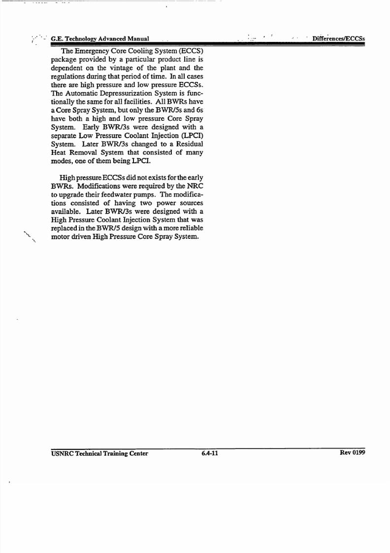
7/30/2019 Ml 023010606
http://slidepdf.com/reader/full/ml-023010606 58/92
G.E. Technology Advanced ManualDieenslC sThe Emergency Core Cooling System (ECCS)
package provided by a particular product line isdependent on the vintage of the plant and the
regulations during that period of time. In all casesthere are high pressure and low pressure ECCSs.
The Automatic Depressurization System is functionally the same for all facilities. All BWRs have
a Core Spray System, but only the BWR/5s and 6shave both a high and low pressure Core Spray
System. Early BWR/3s were designed with a
separate Low Pressure Coolant Injection (LPCI)
System. Later BWR/3s changed to a ResidualHeat Removal System that consisted of many
modes, one of them being LPCI.
High pressure ECCSs did not exists for the early
BWRs. Modifications were required by the NRCto upgrade their feedwater pumps. The modifica
tions consisted of having two power sources
available. Later BWR/3s were designed with aHigh Pressure Coolant Injection System that was
replaced in the BWR/5 design with a more reliable"motordriven High Pressure Core Spray System.
USNRC Technical Training Center 6.4-11 Rev 0199USNRC Technical Training Center 6.4-11
r"
' : Difference~s/CCSs
Rev 0199

7/30/2019 Ml 023010606
http://slidepdf.com/reader/full/ml-023010606 59/92
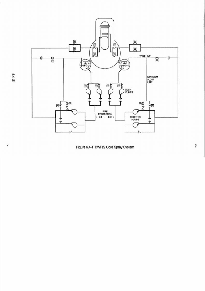
7/30/2019 Ml 023010606
http://slidepdf.com/reader/full/ml-023010606 60/92
och
Figure 6.4-1 BWR/2 Core Spray System
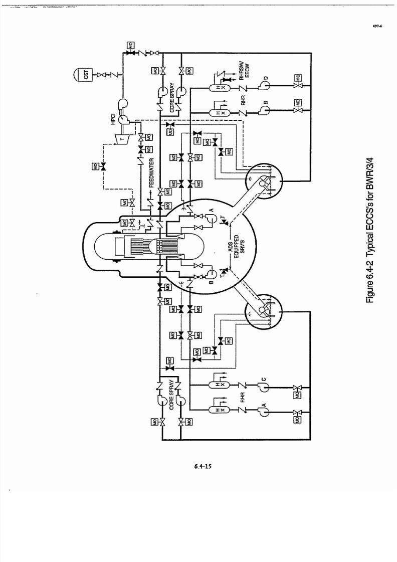
7/30/2019 Ml 023010606
http://slidepdf.com/reader/full/ml-023010606 61/92

7/30/2019 Ml 023010606
http://slidepdf.com/reader/full/ml-023010606 62/92
Rgure 6.4-3 High Pressure Coolant Injection System
,-p
RCICTEST
TO MAINCONDENSER
61--STEAM
L9SUPPLY
SHUTOFFVALVE
8 TURBINESTOPVALVE
9 TURBINEo CONTROL
VALVE
R
178
4. CRW

7/30/2019 Ml 023010606
http://slidepdf.com/reader/full/ml-023010606 63/92
0%
* Minimum.SFowLine MO
MMO
CONDENSATESTORAGE
MO'TANK
SYSTEM I
Figure 6.4-4 Core Spray System (BWR/3/4)
SYSTEM II

7/30/2019 Ml 023010606
http://slidepdf.com/reader/full/ml-023010606 64/92
,J
Figure 6.4-5 LPCI System BWR/3 & some BWR/4's

7/30/2019 Ml 023010606
http://slidepdf.com/reader/full/ml-023010606 65/92
HIGH D/WA LOW LEVELPRESSURE 2 PSI RX LEVEL -59"1i PS PUMPS RUNNING
IF RESPECTIVE
A P > 2.0 PSID
Figure 6.4-6 LOCI Loop Selection Logic
6.4-23

7/30/2019 Ml 023010606
http://slidepdf.com/reader/full/ml-023010606 66/92
SYSTEM I SYSTEM II
Figure 6.4-7 Residual Heat Removal System
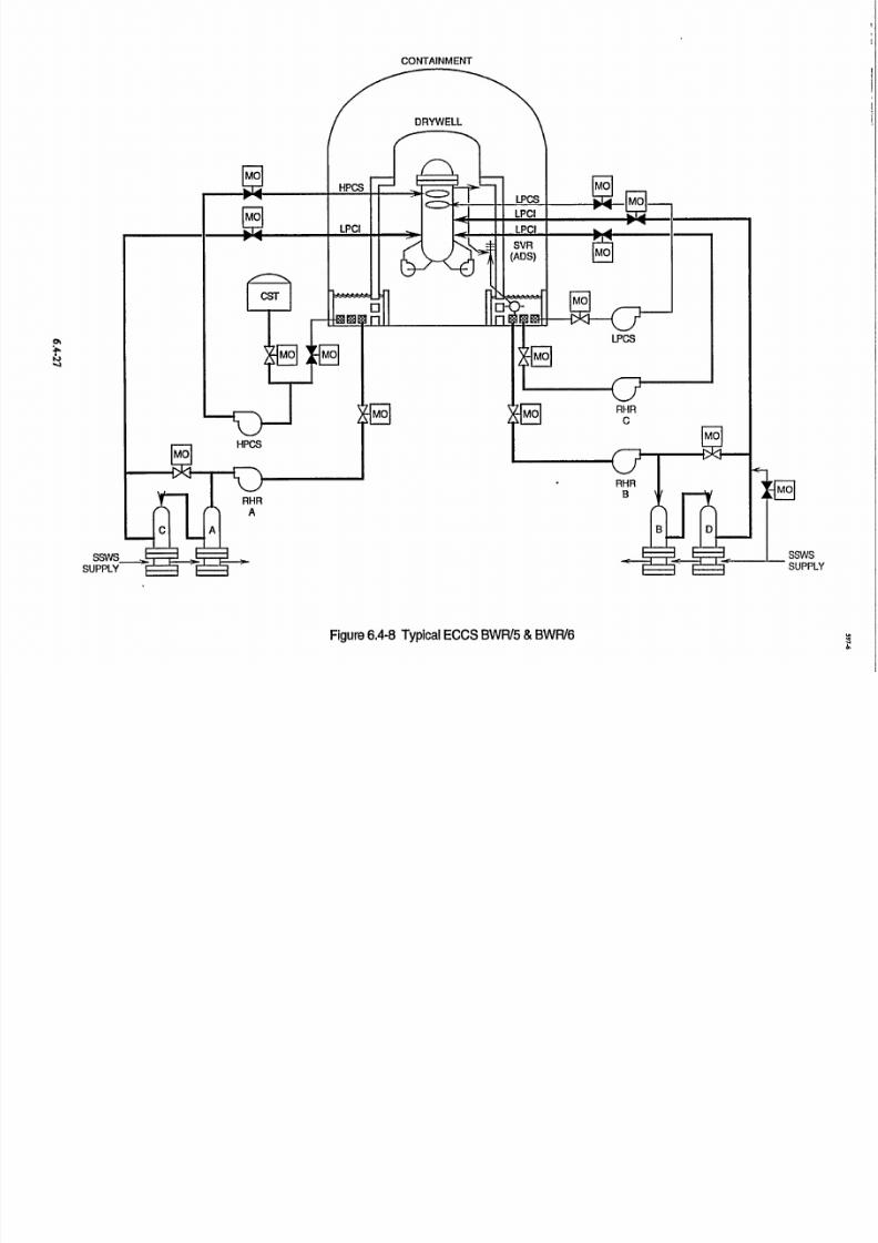
7/30/2019 Ml 023010606
http://slidepdf.com/reader/full/ml-023010606 67/92
CONTAINMENT
SSwSSUPPLY
Figure 6.4-8 Typical ECCS BWR/5 &BWR/6
a' b
-4

7/30/2019 Ml 023010606
http://slidepdf.com/reader/full/ml-023010606 68/92
t ADSi
. CHANNELB
RHR-RESIDUAL HEAT REMOVALHPCS-HIGH PRESSURE CORE SPRAYSSWS-STANDBY SERVICE WATER
LPCS--LOW PRESSURE CORE SPRAYLPCI-LOW PRESSURE COOLANT
INJECTION MODE OF RHR
Figure 6.4-9 ECCS DMsional
ELECTRICAL _ PIPING
6.4-29

7/30/2019 Ml 023010606
http://slidepdf.com/reader/full/ml-023010606 69/92

7/30/2019 Ml 023010606
http://slidepdf.com/reader/full/ml-023010606 70/92
/ 2" STRAINER
1"STRAINERS (14)
CUT AWAY VIEW OF TOP SECTIONS
Fioure 6.4-11 Strainer Assembly
9
P

7/30/2019 Ml 023010606
http://slidepdf.com/reader/full/ml-023010606 71/92
PENETRATION X-303A.
TAP WITH.PLUG
TORUS SHELL
/7SECfDTIN A-A
PENETRATION REINFORCEMENTNOT SHOWN FOR CLARITY
(TYPICAL 4 PLACES)
Figure 6.4-12
99
0.
/
180"
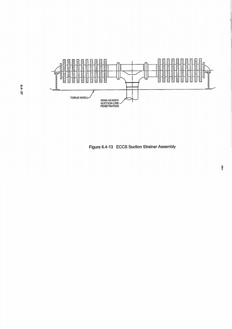
7/30/2019 Ml 023010606
http://slidepdf.com/reader/full/ml-023010606 72/92

7/30/2019 Ml 023010606
http://slidepdf.com/reader/full/ml-023010606 73/92
RC I AZ.,3•5 D.D.P
180
Figure 6.4-14 Mark III Strainer (Clnton)
6.4- 39
1198
27C

7/30/2019 Ml 023010606
http://slidepdf.com/reader/full/ml-023010606 74/92
Figure 6.4-15 RCIC Suction Mark III Containment
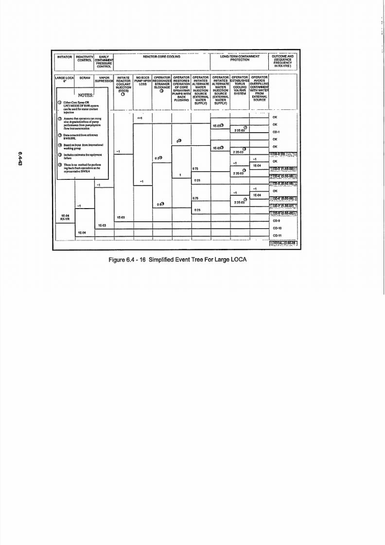
7/30/2019 Ml 023010606
http://slidepdf.com/reader/full/ml-023010606 75/92
r?
INITIATOR REACTMTY EARLYCONTROL CONTAE
PRESSURECONTROL I
REACTOR CORE COOLING
LONG.TERM CONTAINMENT OUTCOME AND]
PROTECTION (SEQUENCEFREQUENCYINRX.YRS)
Figure 6.4 - 16 Simplified Event Tree For Large LOCA
U
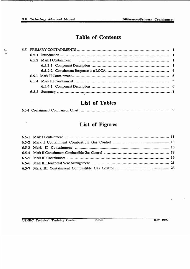
7/30/2019 Ml 023010606
http://slidepdf.com/reader/full/ml-023010606 76/92
G.E. Technology Advanced Manual Differences/Primary Containment
Table of Contents
6.5 PRIMARY CONTAINMENTS ........................................................................... 1
6.5.1 Introduction ......................................................................................... 1
6.5.2 Mark I Containment ......................................................................... 1
6.5.2.1 Component Description ............................................................... 1
6.5.2.2 Containment Response to a LOCA .................................................. 4
6.5.3 Mark HI Containment ............................................................................... 5
6.5.4 Mark m Containment ............................................................................. 5
6.5.4.1 Component Description ............................................................... 6
6.5.5 Summary .......................................................................................... 8
List of Tables
6.5-1 Containment Comparison Chart ........................................................................ 9
List of Figures
6.5-1 Mark I Containment ................................................................................... 11
6.5-2 Mark I Containment Combustible Gas Control .................................................... 13
6.5-3 Mark II Containment ................................................................................... 15
6.5-4 Mark II Containment Combustible Gas Control .................................................. 17
6.5-5 Mark III Containment ................................................................................. 19
6.5-6 Mark III Horizontal Vent Arrangement ........................................................... 21
6.5-7 Mark III Containment Combustible Gas Control .................................................. 23
USNRC Technical Training Center Rev 0497
G.E. Technology Advanced Manual Differences/Primary Containment
6.5-4 Rev 0497USNRC Technical Training Center
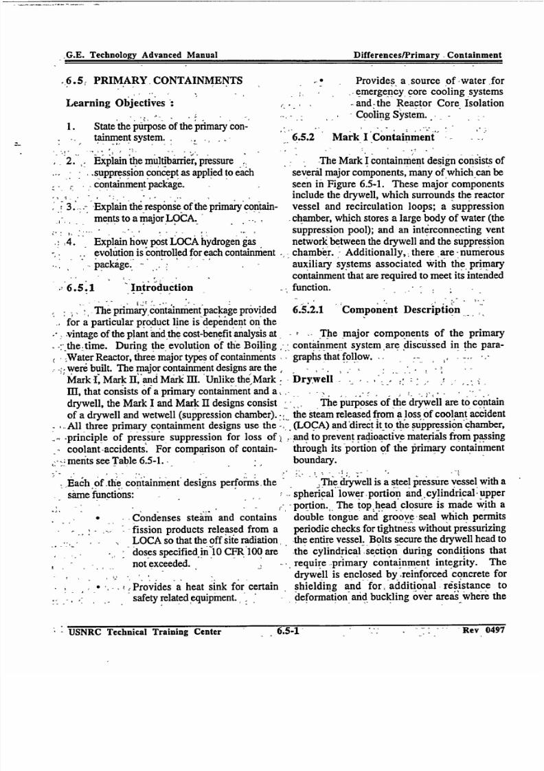
7/30/2019 Ml 023010606
http://slidepdf.com/reader/full/ml-023010606 77/92
G.E. Technology Advanced Manual DifferenceslPrimary Containment
-6.5, PRIMARY, CONTAINMENTS
Learning Objectives :
1. State the purpose of the primary containment system. .
2. ,.Explain the multibarrier,pressuresupprýssion concept as applied to eachcontainment package-
3.' Explain the response of the primary containments to a major LOCA.
4. Explain how post LOCA hydrogen gasevolution is controlled for each containment.package ..
,,6.5.1 Introduction
Provides a source of -water foremergency core cooling systems
-and -the Reactor Core Isolation
Cooling System.
6.5.2 Mark I0Containment
The Mark I containment design consists of
severlil major components, many of which can beseen in Figure 6.5-1. These major componentsinclude the drywell, which surrounds the reactorvessel and recirculation loops; a suppression
chamber, which stores a large body of water (thesuppression pool); and an interconnecting ventnetwork between the drywell and the suppressionchamber. Additionally,: there ,are numerous
auxiliary systems associated with the primary
containment that are required to meet its intendedfunction.
,-The primary containmentpackage prvided 6.5.2.1 Component Description
for a particular product line is dependent on the
-, vintage of the plant and the cost-benefit analysis at - The major components of the primary
-: the~time. During the evolution of the Boiling - containment system are discussed in the para
Water Reactor, three major types of containments graphs that follow. -. - , ,-were built. The major containment designs are the, .
Mark I] Mark II, and Mark iii. 'Unlike the Mark Drywell
III, that consists of a primary containment and a,drywell, the Mark I and Mark II designs consist The purposes of the drywell are to contain
of a drywell and wetwell (suppression chamber). the steam released from a loss of coolant accidentAll three primary containment designs use the- (LOCA) and'directit to the suppression chamber,
Sprinciple of pressure suppression for loss of , and to prevent radioactive materials from passing
coolant-accidents. For comparison of contain- through its portion of the primary containment
merits see Table 6.5-1. boundary.
.-Each Of .the containment designs performs, the
same functions:
- Condenses steam and containsfission products released from a
.-* LOCA so that the off siie radiation. . doses specified in 10 CFR 100 are
. not exceeded. .
. .,, -Provides a heat sink for certainsafety related equipment. ,
" The drywell is a steel pressure vessel with a
.spherical lower-portion and cylindrical upper
portion. The tophead closure is made with a
double tongue and groove-seal which permitsperiodic checks for tightness without pressurizingthe entire vessel. Bolts secure the drywell head to
the cylindrical -section during conditions that
- require -primary containment integrity. The
drywell is enclosed by-.reinforced concrete for
shielding and for, additional -resistance todeformation- and buckling over areas where the
- USNRC Technical Training CenterRev IJ47
,.GE. Technologvy Advanced Manual Differences/Primaryv -Containment
SUSNRC Technical Training Center Rev 0497

7/30/2019 Ml 023010606
http://slidepdf.com/reader/full/ml-023010606 78/92
G.E. Technology Advanced Manual Differences/Primary Containment
concrete backs up the steel shell. Above thefoundation, the drywell is separated from thereinforced concrete by a gap of approximately twoinches for thermal expansion. Shielding over the
top of the drywell is provided by removable,segmented, reinforced concrete shield plugs. Inaddition to the drywell head, one double door
personnel air lock and two bolted equipment
hatches are provided for access to the drywell.
Suppression Chamber
The suppression chamber consists of a steelpressure vessel with a toroidal shape*(sometimesreferred to as a torus) and a large body of water
inside the suppression chamber (referred to as thesuppression pool). The purposes of thesuppression chamber are to condense steam
released from a LOCA and to prevent radioactivematerials from passing through this portion of theprimary containment boundary.
The purposes of the suppression pool areas follows: to serve as a heat sink for LOCAblowdown steam; to serve as a heat sink forsafety/relief valve discharge steam and to serve asa heat sink for high pressure coolant injection(HPCI) system and reactor core isolation cooling
(RCIC) system turbine exhaust steam; to providea source of water for the low pressure coolantinjection (LPCI) miode -of the residual heatremoval (RHR) system, core spiay system, HPCIsystem, and RCIC system,
The suppression chamber is located radiallyoutward and downward from the drywell and is
- held on supports which transmit vertical and"seismicloading to the reinforced foundation slab
of the reactor building.
"Access to the suppression chamber isprovided through two manways with double
gasket bolted covers. These 'access ports
(manwiys) are bolted closed when primarycontaifiment integrity is required and can beopened only when primary coolant temperature is
below 2120F and the pressure suppression systemis not required to be operational.
Interconnecting Vent System
The interconnecting vent network isprovided between the drywell and suppressionchamber to channel the steam and water mixturefrom a LOCA, to the suppression pool and allownoncondensible gases to be vented back to thedrywell. Eight large vent pipes (81" in diameter)extenil radially outward and downward from thedrywell into the suppression chamber. Inside thesuppression chamber the vent pipes exhaust into a
toroidal vent - header which extends
circumferentially all the way around the inside of the suppression chamber. Extending downwardfrom the vent header are ninety-six downcomerpipes which terminate about three feet below thesuppression pool minimum water level. Jetdeflectors are provided in the drywell at theentrance to each- vent- pipe to prevent possibledamage to the vent pipes from jet forces whichmight accmplariy a line break in the drywell. The
'vent pipes are provided with expansiori joints to
accommodate differential motion between4 the
dryiwell and suppression chamber.
Vacuum Relief System
There are two vacuum relief networksassociated with preventing the primary containment from exceeding the design external pressure
of 2 psi. The first vacuum relief network consistsof a set of twelve self actuating swing check valves. These suppression chamber to drywellvacuum relief valves vent noncondensible gases
from the suppression chamber to the drywell
whenever suppression chamber pressure exceedsdrywell pressure by 0.5-psid. The second vacuumrelief network consists' of a set of two vacuumrelief lines from the reactor building (secondarycontainment) to the suppression chamber. Eachline contains a self actuated check valve and an airoperated butterfly type vacuum breaker in series.These reactor building to suppression chamber
USNRC Technical Training Center 6.5-2 Rev 0497
Differences/Primary ContainmentG.E. Technology- Advanced Manual
USNRC Technical Training Center 6.5-2 Rev 0497
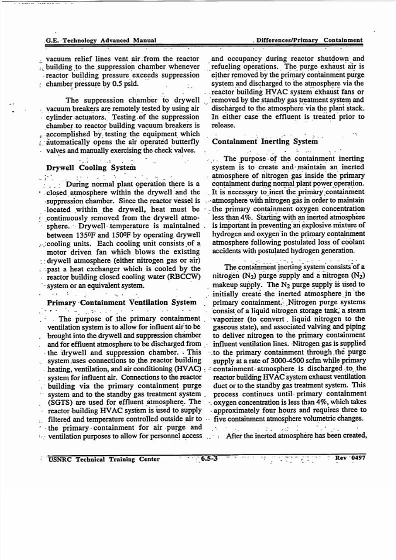
7/30/2019 Ml 023010606
http://slidepdf.com/reader/full/ml-023010606 79/92
G.E.TecnolovAvancd Mnua Differences/Primary Containment
vacuum relief lines vent air from the reactor
building to the suppression chamber whenever
reactor building pressure exceeds suppression
chamber pressure bY 0.5 psid.
The suppression chamber to drywell
vacuum breakers are remotely tested by using air
cylinder-actuators. Testing~of the suppression
chamber to reactor building vacuum breakers is
,accomplished by, testing the equipment which"automatically opens the air operated butterfly
valves and manually exercising the check valves.
Drywell Cooling System'
Duringnormal plant operation there is a
closed. atmosphere within the drywell and the
-suppression chamber. Since the reactor vessel is
located within the drywell, heat must becontinuously removed from the drywell atmo
sphere. -- Drywell -temperature is maintained
between 1350F and 150OF by operating drywell;,-cooling units. Each cooling unit consists of a
motor driven fan which blows the existing
- drywell atmosphere (either nitrogen gas or air)
- past a heat exchanger which is cooled by thereactor building closed cooling water (RBCCW)system or an equivalent system.
Primary -Containment Ventilation System
The purpose of the primary containment
ventilation system is to allow for influent air to be
brought into the drywell and suppression chamber
and for effluent atmosphere to be discharged fromthe drywell and suppression chamber. -.This
system ,uses connections to the reactor building
heating, ventilation, and air conditioning (HVAC)
system for influent air. Connections to the reactorbuilding via the primary containment purge
system and to the standby gas treatment system
(SGTS) are used for effluent atmosphere. The
reactor building HVAC system is used to supply
filtered and temperature controlled outside air to
the primary - containment for air purge and
* ventilation purposes to allow for personnel access
and occupancy during reactor shutdown andrefueling operations. The, purge exhaust air is
either removed by the primary containment purgesystem and discharged to the atmosphere via the
-
reactor building -VAC system exhaust fans orremoved by the standby gas treatment system and
discharged to the atmosphere via the plant stack.
In either case the effluent is treated prior to
release.
Containment Inerting System"
The 'purpose of the containment inerting
system is to create and, maintain an inerted
Satmosphere of nitrogen gas inside the primary
containment during normalplant power operation.
It is necessary to inert the primary containment"atmosphere with nitrogen gas in order to maintain
-the primary containment oxygen concentration
"lessthan 4%. Starting with an inerted atmosphereis important in preventing an explosive mixture of hydrogen and oxygen in the primary containment
atmosphere following postulated loss of coolant
accidents with postulated hydrogen generation.
The containm'ent inerting system consists'of a
nitrogen (N2) purge supply and a nitrogen (N2)
makeup supply. The N2 purge supply is Used to-initially create -the inerted atmosphere in the
primary containment.- Nitrogen purge systems
consist of a'liquid nitrogen storage tank; a steam-vaporizer (to convert, liquid nitrogen to thegaseous state), and associated valving and pipingto deliver nitrogen to the primary containment
influent ventilation lines. -Nitrogen gas is supplied--to the primary containment through the purge
supply at a rate of 3000-4500 scfm while primary-:-containment,atmosphere is dischargedjto, the
reactor building HVAC system exhaust ventilationduct or to the standby gas treatment system. This
process continues until primary containment
- oxygen concentration is less than 4%, which takes*approximately four hours and requires three tofive containment atmosphere volumetric changes.
After the inerted atmosphere has been created,
USNRC Technical Training Center - 6.5-3 Rev 04976.5-3 Rev -0497;USNRC Technical Training Center
-G.E.-Technology Advanced Manual

7/30/2019 Ml 023010606
http://slidepdf.com/reader/full/ml-023010606 80/92
G.E. Technology Advanced Manual DifferenceslPrimary Containment
the nitrogen makeup supply is used to continue tosupply nitrogen gas as required by temperaturechanges'and leakage. The primary containment isheld at a slight positive pressure by the makeup
supply and uses the'same liquid nitrogen storagetank, its own vaporizer, and valvifig and piping to"deliver nitrogen gas at a rate of <60 scfh to theprimairy containment.
Containment Atmosphere Dilution System
The purpose of the containment atmospheredilution (CAD) system is to control the concentration of combustible gases in the primarycontainment subsequent t&-a loss of coolant
accident with postulated high hydrogen generationrates."'The CAD system is °capable of supplyingnitrogen gas at a rate sufficient to maintain theoxygen concentrations of both the drywell andsuppression chamber atmosp'heres below 5% byvolume based oh the hydrogen generation rateassociated with a 5% metal-water reaction.
The CAD system nitrogen supply facilitiesshown in some detail in figure 6.5-2, include twoseparate trains, each of which is capable of supplying nitrogen through separate pipingsystems to the drywell and suppression chamber.Each train includes a liquid nitrogen supply tank,an ambient vaporizer, an electric heater, amanifold with branches to the primary containment; and pressure, flow, and temperaturecontrols. The nitrogen storage tanks have a
nominal capacity of 3000 gallons each:which isadequate for the first seven days of CAD systemoperation. The nitrogen vaporizers use ambientatmosphiere as the heat source. Electric heaters areprovided for use during cold weather to warm the
gas.
Following a LOCA, records are kept of hydrogen and oxygen concentrations andpressures in the drywell and suppression
chamber.,' The CAD. system is then operatedmanually to keep the oxygen concentration <5%or the hydrogen concentration <4% in each
volume. Additions are made separately to thedrywell and suppression chamber.' Manual
initiation of the CAD system is calculated to berequired about 10 days following postulated
design basis LOCA.
When the CAD iystem is adding nitrogen tothe drywell and/or suppression chamber, pressurewill increase. Before drywell pressure reaches 30psig, diywell venting via the standby gastreatment systerrm will be started. Gas releases willbe performed periodically and independently fromthe drywell and suppression chamber.
Releases will be made during periods of the
most favorable meteorological conditions at a rateof approximately 100 scfm until the desiredvolume has been released. Releases will continueover time until primary containment pressure hasbeen reduced to atmospheric. Additions andreleases will be conducted at different times.
6.5.2.2Containment Response to a LOCA
When the postulated line break occurs, thedrywell is immediately pressurized. As drywellpressure increases, drywell atmosphere (primarilynitrogen gas) and steam are blown down throughthe radial vents to the vent header and into thesuppression pool via the downcomers., The steamcondenses in the suppression pool which
suppresses the peak pressure realized in the
drywell. Drywell pressure peaks at 49.6 psig atabout 10 seconds following the line break.
Noncondensible gases discharged& into thesuppression pool end up in the free air volume of the suppression chamber which accounts for thesuppression chamber pressure increase. As
LOCA steam is condensed in the suppression
pool, drywell pressure decreases and stabilizes 27psig while suppression pool temperature reaches
1350F. Drywell pressure decreases to the pointthat suppressionr chamber pressure exceeds it by0.5 psid. This causes the suppressionchamber-drywell vacuum breakers to open andvent noncondensible gases back into the drywell
USNRC Technical Training Center Rev 0497
G.E. Technology Advanced Manual Differences/Primary Containment
USNRC Technical Training Center 6.5-4 Rev 0497

7/30/2019 Ml 023010606
http://slidepdf.com/reader/full/ml-023010606 81/92
G.E. Technology Advanced Manual Differences/Primary Containment
to equalize the drywell and suppression chamberpressures.
Low, pressure emergency core cooling
systers-(ECCS) begin pumping water into thereactorIyessel, removing decay and stored heat
the core. Water injected into the reactorvessel then tasports core heat out of the reactor
vessel via the broken recirculation loop. The hot
water collects on the drywell floor and then flows
into the suppression chamber'via the vent pipes,vent header, ,and downcomer :pipes. Thus a
,closed loop is formed with low pressure ECCSpumps (core spray system and RHR system LPCI
-mode) pumping water from the suppression pool
-'tothe reactor vessel.The water then returns to the
suppression pool and the process is repeated.
- At about .600 seconds it is assumed that theRHR system would be switched from the LPCImode to suppression pool cooling. In this mode
suppression pool heat is removedI via the RHRheat exchangers .causing primary containment
temperature and pressure to decrease. If
- necessary, the containment spray mode of theRHR -system can -.be initiated to spray, cooledsuppression pool water into the drywell and/or
suppression chamber atmospheres to controlprimary containment pressure.
6.5.3 Mark II Containment
-The Mark II primary containment (figures
6.5-3 and 6.5.4) consists-of a steel dome head
and-either a post-tensioned -concrete ,wall,orreinforced concrete'wall standing on a base mat of
-reinforced-concrete. -The inner surface of-the
containment is lined with steel plate which acts as
a leak tight membrane. The containment wall alsoserves •as a support, for ithe floor slabs of thereactor building and for the refueling pools. ,The
floor slabs are resting on corbels that are formed
_as part of the containment wall. The refueling
pools are integrally connected to, and supportedby the concrete containment wall.
The suppression system is the over-and-underconfiguration. The drywell, in the form of a
truncated cone, is located directly above thesuppression pool. The suppression chamber is
cylindrical and separated from the drywell by areinforced concrete slab. The drywell is toppedby an elliptical steel dome called the drywell head.
The drywell inerted atmosphere is vented into the
suppression chamber through a series of
downcomer pipes penetrating and supported bythe drywell floor.
-In order to prevent flooding of the drywell
during refueling,-a bellows type seal is used to
, seal-the space between the reactor vessel and thedrywell:-;The bellows permits free relative movement and offers some restraint to relative lateral
%,displacement of-the RPV and the primary con
tainment vessel..
6.5.4 Mark IH Containment
BWR/6 product lines use the Mark HI
containment concept. The Mark III containment is
a multibarrier, pressure suppression style
containment. The containment structure is similarto a standard dry containment and can be designed
as either a free standings' steel containment
,surrounded by a concrete shield building or as aconcrete pressure vessel with a liner. .The former
design is referred to as the reference design whilethe latter is the alternate.; Discussion in this
"sectionis limited to the reference design.
The primary containment consists of several"majorcomponents, many of which can be seen infigure 6.5-5. The drywell is a cylindrical,
reinforced concrete structure with a removable
*"steel head and encloses the reactor vessel. It is
designed to withstand and confine the steamgenerated during a pipe rupture inside containmentand channel this steam into the suppression poolvia the weir wall and horizontal vents. The
psuppression pool contains a large volume of water
to act as a heat sink and water source for ECCSs.A leak tight cylindrical steel containment vessel
* surrounds the drywell and the suppression pool to
USNRC Technical Training Center - 11CV UQYI
;,Differences/Primary ContainmentG.E. Technology Advanced Manual
- Jev 049 7 -- 'USNRC Technical Training Center

7/30/2019 Ml 023010606
http://slidepdf.com/reader/full/ml-023010606 82/92
G.E. Technology Advanced Manual Differences/Primary Containmentprevent gaseous and particulate fission products
prevent gaseous and particulate fission productsfrom escaping to the environment'
6.5.4.1 Component Description
The major components of the primary containment system are discussed in the paragraphs thatfollow.
Drywell
The drywell is a cylindrical reinforcedconcrete structure with a removable vessel head toallow vertical access to the reactor vessel forrefueling or maintenance. The drywell is
designed for an internal pressure of 30 psig, anexternal pressure of 21 psig, and an internal
temperature of 330 OF. However, a high degreeof leak tightness is not a requirement since thedrywell is not a fission product barrier.
Large diameter horizontal vent openingspenetrate the lower' section of the drywellcylindrical wall to channel steam from a' LOCAinto the suppression pool.
The main function of the drywell is to containthe steam released from a LOCA and direct it intothe suppression pool. Other functions of thedrywell include:
"* provide shielding to reduce containmentradiation levels to allow normal access.
"* provide structural support for the upperpool.
provide support 'structure forplatforms, moi'forails, and
supports.
work pipe
Horizontal Vents and Weir Wall
The weir wall fofifis the inner boundary of thesuppression pool, and is located inside the
'dr)'well. It is constructed of reinforced concreteapproximately two feet thick and lined with a steel
plate on the suppression pool side.
Since the weir wall forms the inside wall of the suppression pool, it contains the'pool and
allows channeling the steam released by a LOCAinto the suppression pool for condensation. Theweir wall height is 25 feet and allows a minimumfreeboard of 5 feet 8 inches.' This freeboard issufficient height to pieveht the suppression poolfrom overflowing into the drywell.
The Mark mI arrangement uses horizontal
vents to conduct the steam from the drywell to thesuppression pool following a LOCA. Figure 6.56 shows an enlarged horizontal and vertical
section of vents. In the vertical 'section, thedrywell wall is penetrated by a series of 27.5 inchdiameter horizontal vent pipes. There are 3 rowsof these horizontal pipes at levels of 7.5, 12 and16.5 feet below the surface of the suppressionpool.- The total pool depth is approximately 20feet. The horizontal section is a partial view of the40 column of vents, vefit annulus, and weir wall.
. 4'
Any buildup of drywell pressure forcesthe water down in the annulus. The higher thepressure in
thedrywell
the greater the depressionand the number of vents that will be uncovered.
Containment
The containment is a free standing cylindricalsteel pressure vessel that surrounds the drywelland suppression Pool to form the primary leak tight barrier to limit fission product leakage duringa LOCA. By design the containment will not leak more than 0.1% of the containment volume in 24hours at a pressure of 15 psig.
Among the postulated LOCAs, some accidentsmay require flooding the containment to removefuel from the reactor and effect repairs. Althoughit is anticipated that for most accidents, defuelingof' the reactor will be accomplished by normalprocedures and equipment,' as 'a contingency tocover undefined damage resulting from a LOCA,
UNKC lechnical 'Iraining Center Rev 0497Rev 0497
G.E. Technology Advanced Manual Differeni~es/Primary Containment
USINRCt Techtnical Training Center O.$-b

7/30/2019 Ml 023010606
http://slidepdf.com/reader/full/ml-023010606 83/92
G.E. Technology Advanced Manual Differences/Primary Containmentthe containment can be flooded to a level 6feet 10
the containment can be flooded to a level 6 feet 10inches above the top of the active fuel in the core.
Upper Pool
The containment upper pool walls are above
the drywell and within the containment column.
The pool is completely lined with stainless steel
plates and consists of five regions:
moisture separator storage
"* reactor well
"* steam dryer storage
"* temporary fuel storage
"* fuel transfer region
The upper pool provides radiation shieldingwhen the reactor is operating, storage for
refueling operation, and a source of water makeup
for the suppression pool following a LOCA.
Combustible Gas Control
To ensure containment integrity is notendangered because of the generation of combustible gases following a postulated LOCA,
the containment is protected by a collection of
systems called the containment combustible gas
control system (CCGC system).
The CCGC system, figure 6.5-7, prevents
hydrogen concentration in the primary contain
ment from exceeding the flammability limit of 4%
(by volume). The system is capable of mixing theatmosphere inside the drywell with that insidecontainment following a LOCA. When the
drywell hydrogen concentration begins to
increase, the drywell mixing compressors arestarted manually by the control room operator.
Air from the containment is pumped into thedrywell increasing drywell pressure. The increase
in drywell pressure depresses the annulus water-uncovering vents and allowing the drywell
atmosphere to mix with the containment.
While drywell mixing continues following aLOCA, hydrogen continues to be produced.
- -Eventually, -the 4% limit is -approached in the
containment, requiring the hydrogen recombiners
and hydrogen ignition system to be manually
placed in operation. The recombiners are locatedin the containment upper region. Air flow
through the recombiner is designed to process 100
cfm of containment air, heating it to 11500F. Theheated air leaving the heater section is mixed with
containment atmosphere to limit the outlet
temperature to approximately 500F above ambient.
The hydrogen ignition system consists of
hydrogen ignitors distributed throughout the
drywell and containment. The ignitors burn the
hydrogen as its evolved to maintain the concentra
tion below detonable limits.
A small line, connecting the drywell with the
shield building annulus, is used during reactor
startup and heatup. Drywell pressure is vented to
the annulus through the bleedoff and backup
purge line. This venting can support plant heatup
at the design rate of 100 oF/hr. If hydrogen
recombiners are not available subsequent to a
LOCA, the drywell bleedoff valves may be
opened for backup purging. This flowpath allowsabout 100 cfm of air from the drywell to enter the
shield building annulus where it is removed andthen later processed by the standby gas treatment
system.
6.5.5 Summary
The primary containment package provided
for a particular product line is dependent on thevintage of the plant and the cost-benefit analysis atthe time. During the evolution of the boiling
water reactor, three major types of containments
were built. The major containment designs are the
USNRC Technical Training Center - KCV IJ'IYi.6.5-7
I Differences/Primary ContainmentI G.E. Technology Advanced -Manual
" ' RevY 0I49 7 •,, USNRC Technical Training Center

7/30/2019 Ml 023010606
http://slidepdf.com/reader/full/ml-023010606 84/92
. Adva.ce.DifferencesPrimarv Containment
Mark I, Mark II, and Mark III. Unlike the Mark IT, that consists of a primary containment and a
drywell, the Mark I and Mark II designs consistof a drywell and wetwell (suppression chamber).
All three primary containment designs use theprinciple of pressure suppression for loss of coolant accidents. For comparison of'containments see table 6.5-1.
USNRCTechnicalTrainingCenter6.5-8 Rev 0497Rev 0497
Technology- Advanced Manual
USNRC Technical Training Center6.5-8

7/30/2019 Ml 023010606
http://slidepdf.com/reader/full/ml-023010606 85/92
G.E. Technology Advanced Manual Differences/Primary Containment
Table 6.5-1 Containment Comparison Chart
Mark I Mark II Mark mI(BFNP) (LaSalle) (Perry)
Drywell Material Steel Concrete Concrete
Drywell Thickness (ft) .17 6 6
Drywell Upper Diameter (ft) 39 31 73
Drywell Lower Diameter (ft) 67 73 73
Drywell Height (ft) 115 91 89
Drywell Free AirVolume (ft3) 159,000 209,300 277,685
Drywell Design Internal Pressure (psig) 56 45 30
Drywell Design External Pressure (psig) 2 5 21
Drywell Deck Design d/p (psid) NIA 25 N/A
Drywell Design Temperature (OF) 281 340 330
Drywell max. Calculated LOCA Pressure (psig) 49.6 34 22.1
Shield above RPV Head Concrete Concrete Water
Suppression Chamber (or Containment ) Thickness (ft) .17 4 .15
Suppression Chamber (or Containment ) Steel Liner Thickness N/A .25 N/A
Suppression Chamber (or Containment) Diameter ft) 111 87 120
Suppression Chamber (or Containment ) Height (ft) 31 67 183
Suppression Chamber (or Containment) Free Air Volume (ft3 ) 119,000 164,500 1,141,014
Suppression Pool Volume in Drywell (ft 3) N/A N/A 11,215
Total Suppression Pool Volume (ft3 ) 135,000 124,000 129,550
Upper Pool Makeup to Suppression Pool (ft3) N/A N/A 32,830
Suppression Chamber (or Containment) Design Internal Pressure 56 45 15
(psig)
Suppression Chamber (or Containment) Design External Pressure 2 5 0.8
(psig)
Suppression Chamber (or Containment) Design Temperature (OF) 281 275 185
Suppression Chamber (or Containment) max. Calculated LOCA 27 28 11.31
Suppression Chamber (or Containment) design Leak Rate (% of .5 .5 .2vol/Day)
Number of Drywell to Suppression Chamber (or Containment) vents 8 98 120
Total Vent Area (ft3) 286 308 512
Drywell Atmosphere N2 N2 Air
USNRC Technical Training Center zev ii
G.E. Technology Advanced Manual Differences/Primary Containment
R~ev £1175USNRC Technical Training Center 041-y
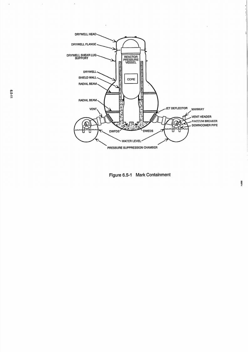
7/30/2019 Ml 023010606
http://slidepdf.com/reader/full/ml-023010606 86/92
"RADIALBEAM
VENT JET DEFLECTOR MANWAY
VENT HEADER
VACCUM BREAKER
,. 4 DOWNCOMER PIPE
PRESSURE SUPPRESSION CHAMBER
Figure 6.5-1 Mark Containment

7/30/2019 Ml 023010606
http://slidepdf.com/reader/full/ml-023010606 87/92
Reactor Bldg.Ventilation
Exhaust
Figure 6.5-2 Mark I Containment Combustible Gas Control
0'aU'
Reactor Bldg.Ventilation
1 Supply

7/30/2019 Ml 023010606
http://slidepdf.com/reader/full/ml-023010606 88/92
REACTORPEDESTAL
DRYWELLDECK
VACUUM
BREAKERS(5)
SUPPORTCOLUMN
(12)
DRYWELL HEAD
DRYWELL
REACTOR VESSEL
SACRIFICIAL SHIELD WALL
- STEEL LINER
- S/R VALVE TAILPIPE
(18)
-EQUIPMENT HANDLING
PLATFORM
0 DOWNCOMER (VENT)
PRESSURE SUPPRESSIONCHAMBER
e WATER LEVEL
QUENCHER (18)
•- REINFORCED CONCRETE
Figure 6.5-3 Mark IIContainment
6.5-15
597-6

7/30/2019 Ml 023010606
http://slidepdf.com/reader/full/ml-023010606 89/92
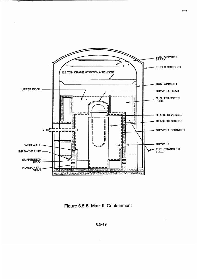
7/30/2019 Ml 023010606
http://slidepdf.com/reader/full/ml-023010606 90/92
597
CONTAINMENTSPRAY
UPPER POOL
WEIR WALL
S/R VALVE LINE
SUPRESSIONPOOL
HORIZONTALVENT
SHIELD BUILDING
CONTAINMENT
DRYWELL HEAD
FUEL TRANSFERPOOL
REACTOR VESSEL
REACTOR SHIELD
DRYWELL BOUNDRY
DRYWELL
FUEL TRANSFERTUBE
Figure 6.5-5 Mark III Containment
6.5-19
7/30/2019 Ml 023010606
http://slidepdf.com/reader/full/ml-023010606 91/92
Drywcll Wall
Weir Wall
15' 6" 24
Containment Wall
-- 18'6"-H--
-18'3"-NN
- - 18'0"- L-------------
Suppression Pool
12' 2"
Figure 6.5-6 Mark III Containment Vent Arrangement
91liJ

7/30/2019 Ml 023010606
http://slidepdf.com/reader/full/ml-023010606 92/92
DAV LO. VmIL IVmLU. / PURGET Breakes 3-Purge Outlet
GLOW PLUG DOW
504, MM OpSHIELD
SBUILDING
Y•'uO m 0--* r000 C
0-~1 F Nin