ml-2 installation instructions 4189340582 rev. j to k, 10 ... · installation instructions...
TRANSCRIPT

INSTALLATION INSTRUCTIONS
Generator Paralleling Controller, GPC-3, and variants Generator Protection Unit, GPU-3, and variants
Paralleling and Protection Unit, PPU-3
• Mounting • Board slot positions • I/O lists • Wiring
Document no.: 4189340582K SW version 3.06.x or later

GPC/GPU/PPU Installation Instructions
DEIF A/S Page 2 of 75
This document is valid for the following products: GPC Software version 3.06.x GPC Gas Software version 3.06.x GPC Hydro Software version 3.06.x GPU Software version 3.06.x GPU Gas Software version 3.06.x GPU Hydro Software version 3.06.x PPU Software version 3.06.x

GPC/GPU/PPU Installation Instructions
DEIF A/S Page 3 of 75
Table of contents
1. ABOUT THIS DOCUMENT ............................................................ 5 GENERAL PURPOSE ............................................................................... 5 INTENDED USERS .................................................................................. 5 CONTENTS/OVERALL STRUCTURE .......................................................... 5 DEFINITIONS ......................................................................................... 5
2. WARNINGS AND LEGAL INFORMATION ................................... 7 LEGAL INFORMATION AND RESPONSIBILITY ............................................. 7 ELECTROSTATIC DISCHARGE AWARENESS ............................................. 7 SAFETY ISSUES ..................................................................................... 7
3. MOUNTING ..................................................................................... 8 MOUNTING OF THE UNIT ......................................................................... 8 PANEL CUTOUT ..................................................................................... 8 MOUNTING INSTRUCTIONS ..................................................................... 8
4. GENERAL HARDWARE DESCRIPTION ...................................... 9 HARDWARE ........................................................................................... 9
5. GPU/GPU HYDRO I/O LIST ........................................................ 12
6. GPC/PPU I/O LIST ....................................................................... 26
7. WIRINGS ....................................................................................... 41 AC CONNECTIONS (3-PHASE) .............................................................. 41 AC CONNECTIONS (1-PHASE) .............................................................. 42 AC CONNECTIONS (2-PHASE) .............................................................. 43 CANBUS LOAD SHARING (OPTION G9) ................................................. 44 MODBUS, RS485 (OPTION H2) ............................................................ 44 MODBUS, RS232 (OPTION H9.2) ......................................................... 48 PROFIBUS DP (OPTION H3) ................................................................. 49 CANBUS ENGINE COMMUNICATION (OPTION H5) .................................. 50 CANBUS ENGINE COMMUNICATION (OPTION H7) .................................. 51 LOAD SHARING LINES........................................................................... 53 MECHANICAL SPEED GOVERNOR .......................................................... 53 AVR WITH RELAY OUTPUTS ................................................................. 54 ELECTRONIC SPEED GOVERNOR .......................................................... 55 AVR WITH ANALOGUE OUTPUTS .......................................................... 56

GPC/GPU/PPU Installation Instructions
DEIF A/S Page 4 of 75
DIGITAL INPUTS ................................................................................... 57 DIGITAL INPUTS WITH WIRE BREAK SUPERVISION (OPTION M4) ............. 57 MULTI-FUNCTIONAL INPUTS (OPTION M4) ............................................. 58 MAGNETIC PICK-UP (MPU) INPUT (OPTION M4) ................................... 60 ANALOGUE INPUTS (OPTION M15.X) .................................................... 61 STOP COIL WITH WIRE BREAK DETECTION (OPTION M4) ........................ 61 TRANSISTOR OUTPUTS ........................................................................ 61 ADDITIONAL DISPLAY UNIT, DU-2 (OPTION X2) ..................................... 63 ADDITIONAL OPERATOR’S PANEL, AOP-1 (OPTION X3) ......................... 64 ADDITIONAL OPERATOR'S PANEL, AOP-2 (OPTION X4) ......................... 65
8. GENERAL DATA .......................................................................... 66 TECHNICAL SPECIFICATIONS ................................................................ 66 DIMENSIONS ....................................................................................... 74

GPC/GPU/PPU Installation Instructions
DEIF A/S Page 5 of 75
1. About this document
General purpose This document is the Installation Instructions for DEIF’s GPC-3, GPU-3 and PPU-3. The document mainly includes general hardware description, I/O lists and wiring descriptions. The general purpose of these installation instructions is to give the user important information to be used in the installation of the controllers.
Intended users These installation instructions are mainly intended for the panel builder designer in charge. On the basis of this document, the panel builder designer will give the electrician the information he needs in order to install the controllers, e.g. detailed electrical drawings. In some cases the electrician may use these installation instructions himself.
Contents/overall structure This document is divided into chapters, and in order to make the structure simple and easy to use, each chapter will begin from the top of a new page.
Definitions Throughout this document a number of notes and warnings will be presented. To ensure that these are noticed, they will be highlighted in order to separate them from the general text.
Please make sure that you read this manual before starting to work with the controllers. Failure to do this could result in damaging the equipment or, even worse, injury of personnel.
GPC/GPU/PPU Installation Instructions
DEIF A/S Page 6 of 75
Notes
Warnings
The warnings indicate a potentially dangerous situation which could result in death, personal injury or damaged equipment, if certain guidelines are not followed.
The notes provide general information which will be helpful for the reader to bear in mind.
GPC/GPU/PPU Installation Instructions
DEIF A/S Page 7 of 75
2. Warnings and legal information
Legal information and responsibility DEIF takes no responsibility for installation or operation of the generator sets. If there is any doubt about how to install or operate the generator sets controlled by the controllers, the company responsible for the installation or the operation of the sets must be contacted.
Electrostatic discharge awareness Sufficient care must be taken to protect the terminals against static discharges during the installation. Once the system is installed and connected, these precautions are no longer necessary.
Safety issues Installing the controllers implies work with dangerous currents and voltages. Therefore, the installation should only be carried out by authorised personnel who understand the risks involved in working with live electrical equipment.
Be aware of the hazardous live currents and voltages. Do not touch any AC measurement inputs as this could lead to injury or death.
The controllers are not to be opened by unauthorised personnel. If opened anyway, the warranty will be lost.

GPC/GPU/PPU Installation Instructions
DEIF A/S Page 8 of 75
3. Mounting
Mounting of the unit The unit is designed for mounting inside the switchboard. The display can be installed on the switchboard door and connected to the main unit with a display cable. The technical specifications in chapter 8 include detailed information about:
Unit dimensions Panel cutout Screw hole positions and dimensions
Panel cutout In order to ensure optimum mounting, the switchboard door must be cut out according to the panel cutout illustration presented in chapter 8.
Mounting instructions For land applications the units can be either DIN-rail or base mounted. For marine applications the units have to be mounted with screws to the rear side of the cabinet. Six screw holes are available for this mounting method.
DEIF recommends using the screw hole fastening.

GPC/GPU/PPU Installation Instructions
DEIF A/S Page 9 of 75
4. General hardware description
Hardware The unit housing is divided into board slot positions. This means that the unit consists of a number of printed circuit boards (PCBs) mounted in numbered slots. The green terminal blocks are then mounted in the PCBs. Some of these board slots are standard, and some are intended for options. The board slot positions are arranged as illustrated below. Slot Term. GPU/GPU
Hydro GPC/PPU Description
Slot #1 1-28 Standard Standard Power supply board Slot #2 29-36 Option Option Option:
H2 (Modbus RS485) H3 (Profibus) H8.2 (Beckhoff ext. I/Os) H9.2 (Modbus RS232) M14.2 (4 x relay outputs)
Slot #3 37-64 Option M12
Standard GPC/PPU: Load sharing and I/O board GPU/GPU Hydro: I/O extension
Slot #4 65-72 Option Standard (4 x relay outputs)
Option: E1 (2 x +/-25 mA output) E2 (2 x 0(4)...20 mA output) EF2 (1 x +/-25 mA, 1 x 0(4)...20 mA) EF4 (1 x +/-25 mA, 2 x relay outputs) EF5 (1 x PWM, +/-25 mA, 2 x relay outputs) EF6 (1 x PWM, 2 x +/-25 mA outputs) M14.4 (4 x relay outputs)
Slot #5 73-89 Standard Standard AC measuring Slot #6 90-97 Option Option Option:
F1 (2 x analogue outputs) M13.6 (7 x binary inputs) M14.6 (4 x relay outputs) M15.6 (4 x analogue inputs)
Slot #7 98-B3 Option Option M4 (engine interface board or I/O extension) - CAN I/F A (H7 - J1939) - CAN I/F B (reserved)
GPC/GPU/PPU Installation Instructions
DEIF A/S Page 10 of 75
Slot Term. GPU/GPU Hydro
GPC/PPU Description
Slot #8 126-133 Option Option Option: G9 (CANbus load sharing) M13.8 (7 x binary inputs) M14.8 (4 x relay outputs) M15.8 (4 x analogue inputs) H5, H6 (engine comm.) H8.8 (Beckhoff ext. I/Os)
Only hardware options which will affect the hardware of the unit are represented in the table. The software options can be seen through the PC utility software. The software options are described in the data sheet.

GPC/GPU/PPU Installation Instructions
DEIF A/S Page 11 of 75
Unit top side overview An overview of the terminals is presented below. The slot positions are the following:
7877
7675
7473
9697
9594
9291
9093
8988
8785
8683
8482
8180
79
7271
6970
6867
6566
6263
5960
6158
5657
5553
5464
5251
5049
4746
4443
4548
4140
3837
3942
Ser
vice
por
tD
ispl
ayP
MS
CA
NE
ngin
e C
AN
Pow
erS
elf c
heck
ok
Ala
rm in
hibi
t
Slot #4 Slot #6
Slot #2
Slot #1
Slot #8
Slot #7
Slot #3 Slot #5

GPC/GPU/PPU Installation Instructions
DEIF A/S Page 12 of 75
5. GPU/GPU Hydro I/O list
Terminal strip description
Slot #1, power supply and binary I/O For the relay outputs the following terms will be used: NO means Normally Open NC means Normally Closed Com. means common terminal for the relay in question Term. Function Technical data Description 1 +12/24V DC 8-36V DC Power supply 2 0V DC 3 NC Status relay Normally closed relay,
processor/power supply status supervision
4 Com. 24 V/1 A
5 NO Relay 5 Alarm horn/configurable 6 Com. 250V AC/8 A 7 NC 8 NO Relay 8 Configurable 9 Com. 250V AC/8 A 10 NC 11 NO Relay 11 Configurable 12 Com. 250V AC/8 A 13 NC 14 NO Relay 14 Open GB 15 Com. 250V AC/8 A 16 NC 17 NO Relay 17 Configurable 18 Com. 250V AC/8 A 19 NC 20 Open collector 1 Transistor out (relay 20) Configurable as standard relay
output 21 Open collector 2 Transistor out (relay 21) Configurable as standard relay
output 22 Com. Common Common terminal for terminals
20 and 21 23 Binary input Optocoupler Alarm inhibit 1/configurable
GPC/GPU/PPU Installation Instructions
DEIF A/S Page 13 of 75
24 Binary input Optocoupler Remote alarm acknowledge/ configurable
25 Binary input Optocoupler Configurable 26 Binary input Optocoupler Configurable 27 Binary input Optocoupler Configurable 28 Com. Common Common for terminals 23-27
The power supply must be protected with a 2 A slow-blow fuse.
GPC/GPU/PPU Installation Instructions
DEIF A/S Page 14 of 75
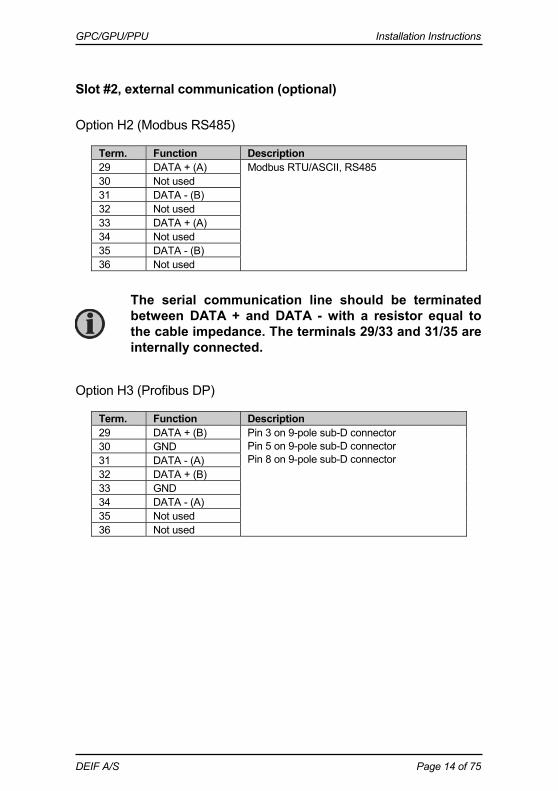
Slot #2, external communication (optional)
Option H2 (Modbus RS485)
Term. Function Description 29 DATA + (A) Modbus RTU/ASCII, RS485 30 Not used 31 DATA - (B) 32 Not used 33 DATA + (A) 34 Not used 35 DATA - (B) 36 Not used
Option H3 (Profibus DP)
Term. Function Description 29 DATA + (B) Pin 3 on 9-pole sub-D connector
Pin 5 on 9-pole sub-D connector Pin 8 on 9-pole sub-D connector
30 GND 31 DATA - (A) 32 DATA + (B) 33 GND 34 DATA - (A) 35 Not used 36 Not used
The serial communication line should be terminated between DATA + and DATA - with a resistor equal to the cable impedance. The terminals 29/33 and 31/35 are internally connected.

GPC/GPU/PPU Installation Instructions
DEIF A/S Page 15 of 75
Option H8.2 CANbus interface for external I/O modules.
Term. Function Description 29 Not used CANbus communication for Beckhoff external
I/O modules 30 Not used 31 CAN-L 32 Not used 33 CAN-H 34 CAN-L 35 Not used 36 CAN-H
Option H9.2 (Modbus RS232)
Term. Function Description 29 Modbus RTU/ASCII, RS232 30 DATA GND 31 32 TxD 33 34 RxD 35 36

GPC/GPU/PPU Installation Instructions
DEIF A/S Page 16 of 75
Slot #3, digital I/Os (option M12)
Term. Function Technical data Description 37 Not available 38 Not available 39 Not available 40 Not available 41 Not available42 Not available43 Binary input Optocoupler Configurable 44 Binary input Optocoupler Configurable 45 Binary input Optocoupler Configurable 46 Binary input Optocoupler Configurable 47 Binary input Optocoupler Configurable 48 Binary input Optocoupler Configurable 49 Binary input Optocoupler Configurable 50 Binary input Optocoupler Configurable 51 Binary input Optocoupler Configurable 52 Binary input Optocoupler Configurable 53 Binary input Optocoupler Configurable 54 Binary input Optocoupler Configurable 55 Binary input Optocoupler Configurable 56 Com. Common Common for terminals 43-55 57 NO Relay 57 6 GOV/AVR control or configurable 58 Com. 250V AC 8 A 59 NO Relay 59 7 GOV/AVR control or configurable 60 Com. 250V AC 8 A 61 NO Relay 61 8 GOV/AVR control or configurable 62 Com. 250V AC 8 A 63 NO Relay 63 9 GOV/AVR control or configurable 64 Com. 250V AC 8 A
AVR control requires options G2 and D1.
GOV control requires option G2.
GPC/GPU/PPU Installation Instructions
DEIF A/S Page 17 of 75
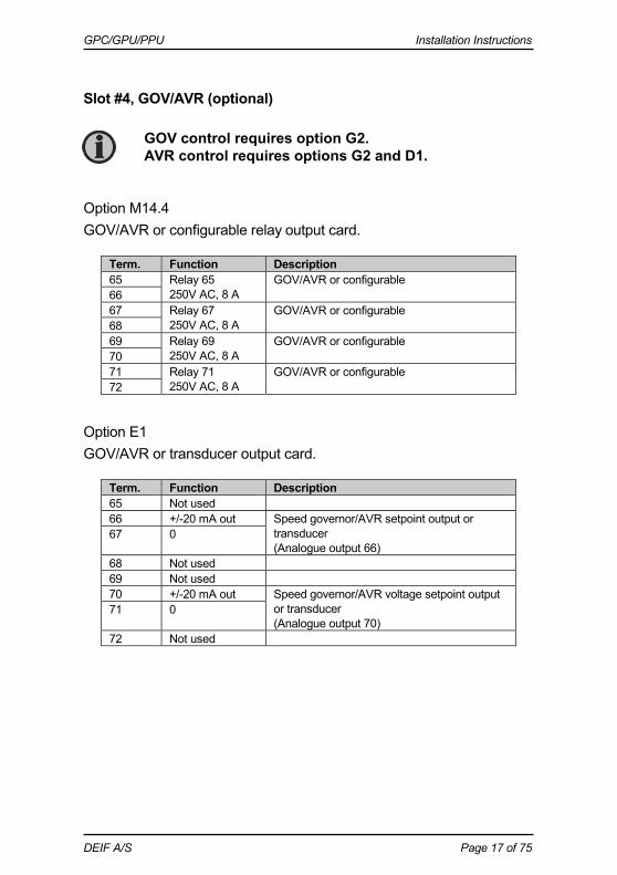
Slot #4, GOV/AVR (optional)
Option M14.4 GOV/AVR or configurable relay output card.
Term. Function Description 65 Relay 65
250V AC, 8 A GOV/AVR or configurable
66 67 Relay 67
250V AC, 8 A GOV/AVR or configurable
68 69 Relay 69
250V AC, 8 A GOV/AVR or configurable
70 71 Relay 71
250V AC, 8 A GOV/AVR or configurable
72
Option E1 GOV/AVR or transducer output card.
Term. Function Description 65 Not used 66 +/-20 mA out Speed governor/AVR setpoint output or
transducer (Analogue output 66)
67 0
68 Not used 69 Not used 70 +/-20 mA out Speed governor/AVR voltage setpoint output
or transducer (Analogue output 70)
71 0
72 Not used
GOV control requires option G2. AVR control requires options G2 and D1.

GPC/GPU/PPU Installation Instructions
DEIF A/S Page 18 of 75
Option E2 GOV/AVR or transducer output card.
Term. Function Description 65 Not used 66 0-20 mA out Speed governor/AVR setpoint output or
transducer (Analogue output 66)
67 0
68 Not used 69 Not used 70 0-20 mA out Speed governor/AVR voltage setpoint output
or transducer (Analogue output 70)
71 0
72 Not used
Option EF2 GOV/AVR or transducer output card.
Term. Function Description 65 Not used 66 +/-20 mA Speed governor/AVR setpoint output or
transducer (Analogue output 66)
67 0
68 Not used 69 Not used 70 0(4)-20 mA out Speed governor/AVR setpoint output or
transducer (Analogue output 70)
71 0
72 Not used
Option EF4 GOV/AVR or transducer combination output card.
Term. Function Description 65 ANA + Speed governor/AVR setpoint output or
transducer (Analogue output 66)
66 ANA -
67 Not used 68 Not used 69 Relay 69
250V AC, 8 A GOV/AVR control or configurable
70 71 Relay 71
250V AC, 8 A GOV/AVR control or configurable
72
GPC/GPU/PPU Installation Instructions
DEIF A/S Page 19 of 75
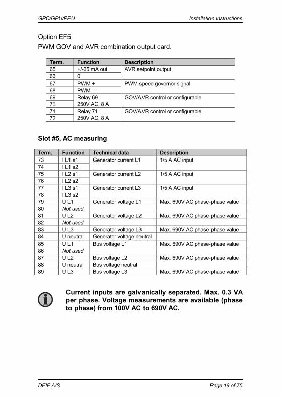
Option EF5 PWM GOV and AVR combination output card.
Term. Function Description 65 +/-25 mA out AVR setpoint output
66 0 67 PWM + PWM speed governor signal 68 PWM - 69 Relay 69
250V AC, 8 A GOV/AVR control or configurable
70 71 Relay 71
250V AC, 8 A GOV/AVR control or configurable
72
Slot #5, AC measuring
Term. Function Technical data Description 73 I L1 s1 Generator current L1 1/5 A AC input 74 I L1 s2 75 I L2 s1 Generator current L2 1/5 A AC input 76 I L2 s2 77 I L3 s1 Generator current L3 1/5 A AC input 78 I L3 s2 79 U L1 Generator voltage L1 Max. 690V AC phase-phase value 80 Not used 81 U L2 Generator voltage L2 Max. 690V AC phase-phase value 82 Not used 83 U L3 Generator voltage L3 Max. 690V AC phase-phase value 84 U neutral Generator voltage neutral 85 U L1 Bus voltage L1 Max. 690V AC phase-phase value 86 Not used 87 U L2 Bus voltage L2 Max. 690V AC phase-phase value 88 U neutral Bus voltage neutral 89 U L3 Bus voltage L3 Max. 690V AC phase-phase value
Current inputs are galvanically separated. Max. 0.3 VA per phase. Voltage measurements are available (phase to phase) from 100V AC to 690V AC.

GPC/GPU/PPU Installation Instructions
DEIF A/S Page 20 of 75
Slot #6, I/O extension (optional)
Option F1 Transducer output card.
Term. Function Description 90 Not used 91 0 Analogue output 91, selectable 92 0(4)-20 mA out 93 Not used 94 Not used 95 0 Analogue output 95, selectable 96 0(4)-20 mA out 97 Not used
Option M13.6 7 x binary inputs.
Term. Function Description 90 Common Common 91 Digital input 91 Configurable 92 Digital input 92 Configurable 93 Digital input 93 Configurable 94 Digital input 94 Configurable 95 Digital input 95 Configurable 96 Digital input 96 Configurable 97 Digital input 97 Configurable
Option M14.6 4 x relay outputs.
Term. Function Description 90 Relay 90
250V AC, 8 A max. Configurable
91 92 Relay 92
250V AC, 8 A max. Configurable
93 94 Relay 94
250V AC, 8 A max. Configurable
95 96 Relay 96
250V AC, 8 A max. Configurable
97
GPC/GPU/PPU Installation Instructions
DEIF A/S Page 21 of 75
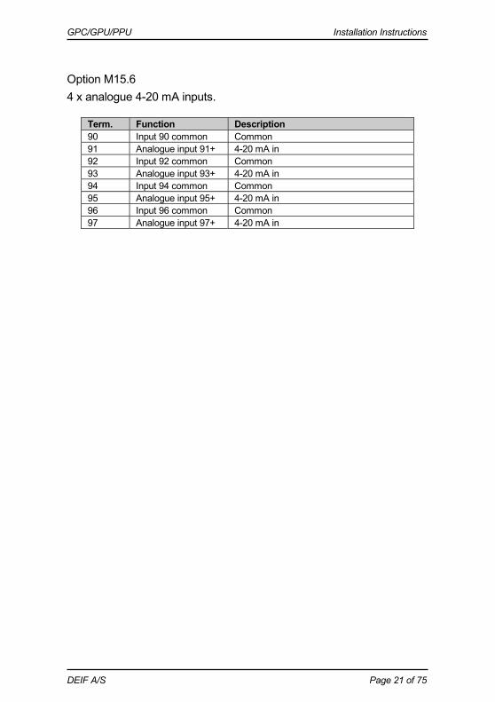
Option M15.6 4 x analogue 4-20 mA inputs.
Term. Function Description 90 Input 90 common Common 91 Analogue input 91+ 4-20 mA in 92 Input 92 common Common 93 Analogue input 93+ 4-20 mA in 94 Input 94 common Common 95 Analogue input 95+ 4-20 mA in 96 Input 96 common Common 97 Analogue input 97+ 4-20 mA in

GPC/GPU/PPU Installation Instructions
DEIF A/S Page 22 of 75
Slot #7, engine interface board (option M4)
Term. Function Technical data Description/preconfiguration 98 +12/24V DC 8-36V DC DC power supply 99 0V DC 100 MPU input 0.5-70V AC/
10-10000 Hz Magnetic pick-up (RPM)
101 MPU GND 102 A 0(4)-20 mA
Digital w/wire break Pt100 Pt1000 RMI 0-40V DC
Multi-input 1 Preselected to digital input with wire break detection
103 B 104 C 105 A Multi-input 2
Preselected to digital input with wire break detection
106 B 107 C 108 A Multi-input 3
Preselected to digital input with wire break detection
109 B 110 C 111 Com. Common Common for terminals 112-117 112 Digital input 112 Optocoupler Configurable 113 Digital input 113 Optocoupler Configurable 114 Digital input 114 Optocoupler Shutdown override/configurable 115 Digital input 115 Optocoupler Configurable 116 Digital input 116 Optocoupler Running feedback/configurable 117 Digital input 117 Optocoupler Configurable 118 Digital input 118 Optocoupler Emergency stop and common for
119 and 120 119 NO Relay 24V DC/5 A Run coil/configurable 120 NO Relay 24V DC/5 A Start prepare/configurable 121 Com. Relay 24V DC/5 A Crank (starter)/configurable 122 NO 123 Com. Relay 24V DC/5 A Stop coil w/wire break/configurable 124 NO A1 CAN-H CANbus CANbus J1939 engine interface
(option H7) A2 CAN GND A3 CAN-L
GPC/GPU/PPU Installation Instructions
DEIF A/S Page 23 of 75
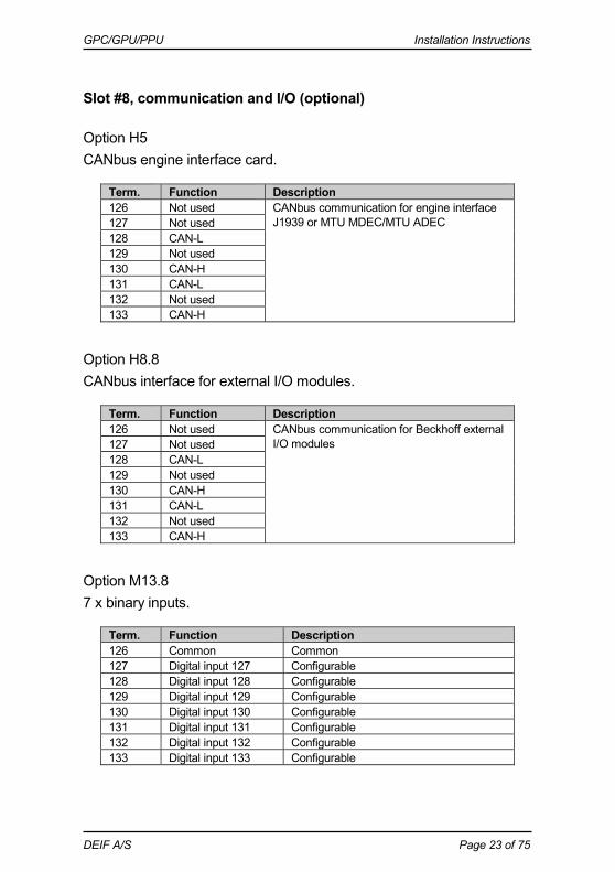
Slot #8, communication and I/O (optional)
Option H5 CANbus engine interface card.
Term. Function Description 126 Not used CANbus communication for engine interface
J1939 or MTU MDEC/MTU ADEC 127 Not used 128 CAN-L 129 Not used 130 CAN-H 131 CAN-L 132 Not used 133 CAN-H
Option H8.8 CANbus interface for external I/O modules.
Term. Function Description 126 Not used CANbus communication for Beckhoff external
I/O modules 127 Not used 128 CAN-L 129 Not used 130 CAN-H 131 CAN-L 132 Not used 133 CAN-H
Option M13.8 7 x binary inputs.
Term. Function Description 126 Common Common 127 Digital input 127 Configurable 128 Digital input 128 Configurable 129 Digital input 129 Configurable 130 Digital input 130 Configurable 131 Digital input 131 Configurable 132 Digital input 132 Configurable 133 Digital input 133 Configurable
GPC/GPU/PPU Installation Instructions
DEIF A/S Page 24 of 75
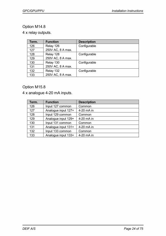
Option M14.8 4 x relay outputs.
Term. Function Description 126 Relay 126
250V AC, 8 A max. Configurable
127 128 Relay 128
250V AC, 8 A max. Configurable
129 130 Relay 130
250V AC, 8 A max. Configurable
131 132 Relay 132
250V AC, 8 A max. Configurable
133
Option M15.8 4 x analogue 4-20 mA inputs.
Term. Function Description 126 Input 127 common Common 127 Analogue input 127+ 4-20 mA in 128 Input 129 common Common 129 Analogue input 129+ 4-20 mA in 130 Input 131 common Common 131 Analogue input 131+ 4-20 mA in 132 Input 133 common Common 133 Analogue input 133+ 4-20 mA in
GPC/GPU/PPU Installation Instructions
DEIF A/S Page 25 of 75
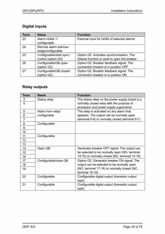
Digital inputs
Term. Name Function 23 Alarm inhibit 1/
configurable External input for inhibit of selected alarms
24 Remote alarm acknow-ledge/configurable
25 Configurable/start sync./ control (option G2)
Option G2: Activates synchronisation. The Deload function is used to open the breaker
26 Configurable/GB open (option G2)
Option G2: Breaker feedback signal. The connection breaker is in position OFF
27 Configurable/GB closed (option G2)
Option G2: Breaker feedback signal. The connection breaker is in position ON
Relay outputs
Term. Name Function 3 Status relay The status relay on the power supply board is a
normally closed relay with the purpose of processor and power supply supervision
4
5 Alarm horn relay/ configurable
The relay is activated on any alarm that appears. The output can be normally open (terminal 5-6) or normally closed (terminal 6-7)
6 7 8 Configurable 9 10 11 Configurable 12 13 14 Open GB Generator breaker OFF signal. The output can
be selected to be normally open (NO, terminal 14-15) or normally closed (NC, terminal 15-16)
15 16 17 Configurable/close GB Option G2: Generator breaker ON signal. The
output can be selected to be normally open (NO, terminal 17-18) or normally closed (NC, terminal 18-19)
18 19
20 Configurable Configurable digital output (transistor output type)
21 Configurable Configurable digital output (transistor output type)
GPC/GPU/PPU Installation Instructions
DEIF A/S Page 26 of 75
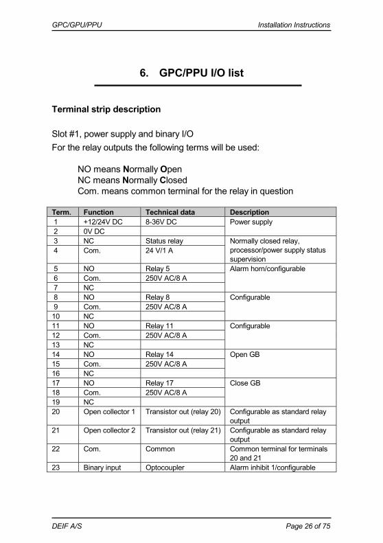
6. GPC/PPU I/O list
Terminal strip description
Slot #1, power supply and binary I/O For the relay outputs the following terms will be used: NO means Normally Open NC means Normally Closed Com. means common terminal for the relay in question Term. Function Technical data Description 1 +12/24V DC 8-36V DC Power supply 2 0V DC 3 NC Status relay Normally closed relay,
processor/power supply status supervision
4 Com. 24 V/1 A
5 NO Relay 5 Alarm horn/configurable 6 Com. 250V AC/8 A 7 NC 8 NO Relay 8 Configurable 9 Com. 250V AC/8 A 10 NC 11 NO Relay 11 Configurable 12 Com. 250V AC/8 A 13 NC 14 NO Relay 14 Open GB 15 Com. 250V AC/8 A 16 NC 17 NO Relay 17 Close GB 18 Com. 250V AC/8 A 19 NC 20 Open collector 1 Transistor out (relay 20) Configurable as standard relay
output 21 Open collector 2 Transistor out (relay 21) Configurable as standard relay
output 22 Com. Common Common terminal for terminals
20 and 21 23 Binary input Optocoupler Alarm inhibit 1/configurable

GPC/GPU/PPU Installation Instructions
DEIF A/S Page 27 of 75
24 Binary input Optocoupler Remote alarm acknowledge/ configurable
25 Binary input Optocoupler Start sync./control/configurable 26 Binary input Optocoupler GB open 27 Binary input Optocoupler GB closed 28 Com. Common Common for terminals 23-27
The power supply must be protected with a 2 A slow-blow fuse.
GPC/GPU/PPU Installation Instructions
DEIF A/S Page 28 of 75
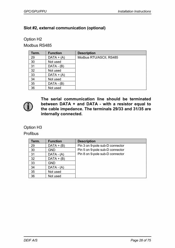
Slot #2, external communication (optional)
Option H2 Modbus RS485
Term. Function Description 29 DATA + (A) Modbus RTU/ASCII, RS485 30 Not used 31 DATA - (B) 32 Not used 33 DATA + (A) 34 Not used 35 DATA - (B) 36 Not used
Option H3 Profibus
Term. Function Description 29 DATA + (B) Pin 3 on 9-pole sub-D connector
Pin 5 on 9-pole sub-D connector Pin 8 on 9-pole sub-D connector
30 GND 31 DATA - (A) 32 DATA + (B) 33 GND 34 DATA - (A) 35 Not used 36 Not used
The serial communication line should be terminated between DATA + and DATA - with a resistor equal to the cable impedance. The terminals 29/33 and 31/35 are internally connected.
GPC/GPU/PPU Installation Instructions
DEIF A/S Page 29 of 75
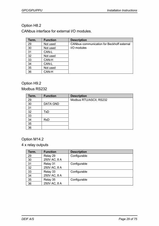
Option H8.2 CANbus interface for external I/O modules.
Term. Function Description 29 Not used CANbus communication for Beckhoff external
I/O modules 30 Not used 31 CAN-L 32 Not used 33 CAN-H 34 CAN-L 35 Not used 36 CAN-H
Option H9.2 Modbus RS232
Term. Function Description 29 Modbus RTU/ASCII, RS232 30 DATA GND 31 32 TxD 33 34 RxD 35 36
Option M14.2 4 x relay outputs
Term. Function Description 29 Relay 29
250V AC, 8 A Configurable
30 31 Relay 31
250V AC, 8 A Configurable
32 33 Relay 33
250V AC, 8 A Configurable
34 35 Relay 35
250V AC, 8 A Configurable
36

GPC/GPU/PPU Installation Instructions
DEIF A/S Page 30 of 75
Slot #3, digital I/O
Term. Function Technical data Description 37 -5…0…5V DC Analogue I/O Active load sharing line 38 Com. Common Common for load sharing lines 39 -5…0…5V DC Analogue I/O Reactive load sharing 40 -10…0…10V DC Analogue input f/P setpoint (passive) 41 Com. Common Common for 40/42 42 -10…0…10V DC Analogue input U/Q setpoint (passive) 43 Binary input Optocoupler Deload/configurable 44 Binary input Optocoupler Man. GOV UP/configurable 45 Binary input Optocoupler Man. GOV DOWN/configurable 46 Binary input Optocoupler Man. AVR UP/configurable 47 Binary input Optocoupler Man. AVR DOWN/configurable 48 Binary input Optocoupler Fixed frequency/configurable 49 Binary input Optocoupler P load sharing/configurable 50 Binary input Optocoupler Ext. GOV setpoint/configurable 51 Binary input Optocoupler Fixed voltage/configurable 52 Binary input Optocoupler Q load sharing/configurable 53 Binary input Optocoupler Ext. AVR setpoint/configurable 54 Binary input Optocoupler Configurable 55 Binary input Optocoupler Configurable 56 Com. Common Common for terminals 43-55 57 NO Relay 57 6 GOV/AVR control or configurable 58 Com. 250V AC 8 A 59 NO Relay 59 7 GOV/AVR control or configurable 60 Com. 250V AC 8 A 61 NO Relay 61 8 GOV/AVR control or configurable 62 Com. 250V AC 8 A 63 NO Relay 63 9 GOV/AVR control or configurable 64 Com. 250V AC 8 A
AVR control requires option D1.
GPC/GPU/PPU Installation Instructions
DEIF A/S Page 31 of 75
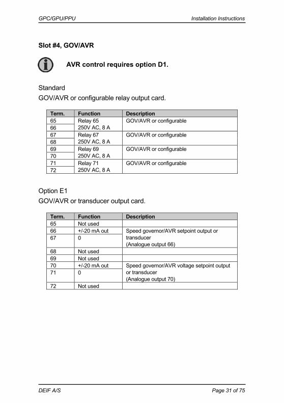
Slot #4, GOV/AVR
Standard GOV/AVR or configurable relay output card.
Term. Function Description 65 Relay 65
250V AC, 8 A GOV/AVR or configurable
66 67 Relay 67
250V AC, 8 A GOV/AVR or configurable
68 69 Relay 69
250V AC, 8 A GOV/AVR or configurable
70 71 Relay 71
250V AC, 8 A GOV/AVR or configurable
72
Option E1 GOV/AVR or transducer output card.
Term. Function Description 65 Not used 66 +/-20 mA out Speed governor/AVR setpoint output or
transducer (Analogue output 66)
67 0
68 Not used 69 Not used 70 +/-20 mA out Speed governor/AVR voltage setpoint output
or transducer (Analogue output 70)
71 0
72 Not used
AVR control requires option D1.

GPC/GPU/PPU Installation Instructions
DEIF A/S Page 32 of 75
Option E2 GOV/AVR or transducer output card.
Term. Function Description 65 Not used 66 0-20 mA out Speed governor/AVR setpoint output or
transducer (Analogue output 66)
67 0
68 Not used 69 Not used 70 0-20 mA out Speed governor/AVR voltage setpoint output
or transducer (Analogue output 70)
71 0
72 Not used
Option EF2 GOV/AVR or transducer output card.
Term. Function Description 65 Not used 66 +/-20 mA Speed governor/AVR setpoint output or
transducer (Analogue output 66)
67 0
68 Not used 69 Not used 70 0(4)-20 mA out Speed governor/AVR setpoint output or
transducer (Analogue output 70)
71 0
72 Not used
Option EF4 GOV/AVR or transducer combination output card.
Term. Function Description 65 ANA + Speed governor/AVR setpoint output or
transducer (Analogue output 66)
66 ANA -
67 Not used 68 Not used 69 Relay 69
250V AC, 8 A GOV/AVR control or configurable
70 71 Relay 71
250V AC, 8 A GOV/AVR control or configurable
72

GPC/GPU/PPU Installation Instructions
DEIF A/S Page 33 of 75
Option EF5 PWM GOV and AVR combination output card.
Term. Function Description 65 +/-25 mA out AVR setpoint output
66 0 67 PWM + PWM speed governor signal 68 PWM - 69 Relay 69
250V AC, 8 A GOV/AVR control or configurable
70 71 Relay 71
250V AC, 8 A GOV/AVR control or configurable
72
Option EF6 PWM GOV and AVR combination output card.
Term. Function Description 65 Not used 66 Not used 67 0 Speed governor, AVR or transducer output 68 68 +/-25 mA out 69 PWM + PWM speed governor signal 70 PWM - 71 0 Speed governor, AVR or transducer output 72 72 +/-25 mA out
Option EF6 is not available for PPU.
GPC/GPU/PPU Installation Instructions
DEIF A/S Page 34 of 75
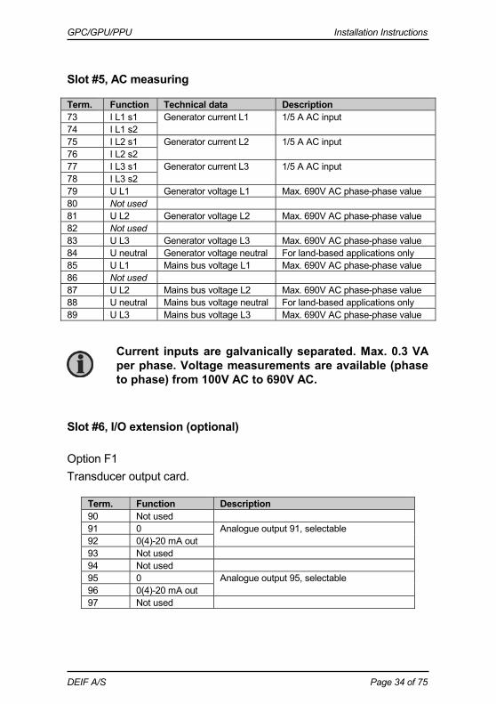
Slot #5, AC measuring
Term. Function Technical data Description 73 I L1 s1 Generator current L1 1/5 A AC input 74 I L1 s2 75 I L2 s1 Generator current L2 1/5 A AC input 76 I L2 s2 77 I L3 s1 Generator current L3 1/5 A AC input 78 I L3 s2 79 U L1 Generator voltage L1 Max. 690V AC phase-phase value 80 Not used 81 U L2 Generator voltage L2 Max. 690V AC phase-phase value 82 Not used 83 U L3 Generator voltage L3 Max. 690V AC phase-phase value 84 U neutral Generator voltage neutral For land-based applications only 85 U L1 Mains bus voltage L1 Max. 690V AC phase-phase value 86 Not used 87 U L2 Mains bus voltage L2 Max. 690V AC phase-phase value 88 U neutral Mains bus voltage neutral For land-based applications only 89 U L3 Mains bus voltage L3 Max. 690V AC phase-phase value
Slot #6, I/O extension (optional)
Option F1 Transducer output card.
Term. Function Description 90 Not used 91 0 Analogue output 91, selectable 92 0(4)-20 mA out 93 Not used 94 Not used 95 0 Analogue output 95, selectable 96 0(4)-20 mA out 97 Not used
Current inputs are galvanically separated. Max. 0.3 VA per phase. Voltage measurements are available (phase to phase) from 100V AC to 690V AC.

GPC/GPU/PPU Installation Instructions
DEIF A/S Page 35 of 75
Option M13.6 7 x binary inputs.
Term. Function Description 90 Common Common 91 Digital input 91 Configurable 92 Digital input 92 Configurable 93 Digital input 93 Configurable 94 Digital input 94 Configurable 95 Digital input 95 Configurable 96 Digital input 96 Configurable 97 Digital input 97 Configurable
Option M14.6 4 x relay outputs.
Term. Function Description 90 Relay output 90
250V AC, 8 A max. Configurable
91 92 Relay output 92
250V AC, 8 A max. Configurable
93 94 Relay output 94
250V AC, 8 A max. Configurable
95 96 Relay output 96
250V AC, 8 A max. Configurable
97
Option M15.6 4 x analogue 4-20 mA inputs.
Term. Function Description 90 Input 90 common Common 91 Analogue input 91+ 4-20 mA in 92 Input 92 common Common 93 Analogue input 93+ 4-20 mA in 94 Input 94 common Common 95 Analogue input 95+ 4-20 mA in 96 Input 96 common Common 97 Analogue input 97+ 4-20 mA in

GPC/GPU/PPU Installation Instructions
DEIF A/S Page 36 of 75
Slot #7, engine interface board (option M4)
Term. Function Technical data Description/preconfiguration 98 +12/24V DC 8-36V DC DC power supply 99 0V DC 100 MPU input 0.5-70V AC/
10-10000 Hz Magnetic pick-up
101 MPU GND 102 A 0(4)-20 mA
Digital w/wire break Pt100 Pt1000 RMI 0-40V DC
Multi-input 1 Preselected to digital input with wire break detection
103 B 104 C 105 A Multi-input 2
Preselected to digital input with wire break detection
106 B 107 C 108 A Multi-input 3
Preselected to digital input with wire break detection
109 B 110 C 111 Com. Common Common for terminals 112-117 112 Digital input 112 Optocoupler Configurable 113 Digital input 113 Optocoupler Configurable 114 Digital input 114 Optocoupler Shutdown override/configurable 115 Digital input 115 Optocoupler Configurable 116 Digital input 116 Optocoupler Running feedback/configurable 117 Digital input 117 Optocoupler Configurable 118 Digital input 118 Optocoupler Emergency stop and common for
119 and 120 119 NO Relay 24V DC/5 A Run coil/configurable 120 NO Relay 24V DC/5 A Start prepare/configurable 121 Com. Relay 24V DC/5 A Crank (starter)/configurable 122 NO 123 Com. Relay 24V DC/5 A Stop coil w/wire break/configurable 124 NO A1 CAN-H CANbus CANbus J1939 engine interface
(option H7) A2 CAN GND A3 CAN-L
GPC/GPU/PPU Installation Instructions
DEIF A/S Page 37 of 75
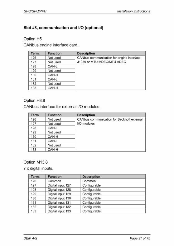
Slot #8, communication and I/O (optional)
Option H5 CANbus engine interface card.
Term. Function Description 126 Not used CANbus communication for engine interface
J1939 or MTU MDEC/MTU ADEC 127 Not used 128 CAN-L 129 Not used 130 CAN-H 131 CAN-L 132 Not used 133 CAN-H
Option H8.8 CANbus interface for external I/O modules.
Term. Function Description 126 Not used CANbus communication for Beckhoff external
I/O modules 127 Not used 128 CAN-L 129 Not used 130 CAN-H 131 CAN-L 132 Not used 133 CAN-H
Option M13.8 7 x digital inputs.
Term. Function Description 126 Common Common 127 Digital input 127 Configurable 128 Digital input 128 Configurable 129 Digital input 129 Configurable 130 Digital input 130 Configurable 131 Digital input 131 Configurable 132 Digital input 132 Configurable 133 Digital input 133 Configurable
GPC/GPU/PPU Installation Instructions
DEIF A/S Page 38 of 75
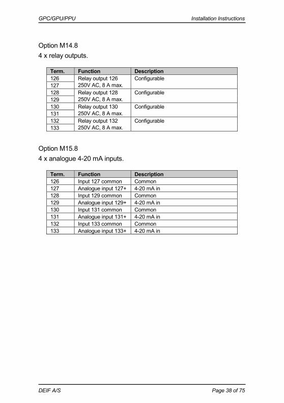
Option M14.8 4 x relay outputs.
Term. Function Description 126 Relay output 126
250V AC, 8 A max. Configurable
127 128 Relay output 128
250V AC, 8 A max. Configurable
129 130 Relay output 130
250V AC, 8 A max. Configurable
131 132 Relay output 132
250V AC, 8 A max. Configurable
133
Option M15.8 4 x analogue 4-20 mA inputs.
Term. Function Description 126 Input 127 common Common 127 Analogue input 127+ 4-20 mA in 128 Input 129 common Common 129 Analogue input 129+ 4-20 mA in 130 Input 131 common Common 131 Analogue input 131+ 4-20 mA in 132 Input 133 common Common 133 Analogue input 133+ 4-20 mA in

GPC/GPU/PPU Installation Instructions
DEIF A/S Page 39 of 75
Digital inputs
Term. Name Function 23 Alarm inhibit 1/configurable External input for inhibit of selected alarms 24 Remote alarm acknowledge/
configurable Remote alarm acknowledge
25 Start sync./control/ configurable
Activates the regulation and synchronisation. Works together with ‘Deload’ (43)
26 GB open Breaker feedback signal. The connection breaker is in position OFF
27 GB closed Breaker feedback signal. The connection breaker is in position ON
43 Deload/configurable Activates the deload sequence. Works together with start sync./control (25)
44 Manual GOV UP/ configurable
Increase engine speed
45 Manual GOV DOWN/ configurable
Decrease engine speed
46 Manual AVR UP/ configurable
Option D1: Increase generator voltage
47 Manual AVR DOWN/ configurable
Option D1: Decrease generator voltage
48 Fixed frequency/configurable Activates frequency controller 49 P load sharing/configurable Activates load sharing controller 50 Ext. GOV setpoint/
configurable The nominal frequency setpoint will be controlled from the analogue inputs terminal 40/41. The internal setpoint will not be used
51 Fixed voltage/configurable Activates voltage controller 52 Q load sharing/configurable Activates Q load sharing controller 53 Ext. AVR setpoint/
configurable The nominal voltage setpoint will be controlled from the analogue inputs terminal 41/42. The internal setpoint will not be used
54 Configurable 55 Configurable

GPC/GPU/PPU Installation Instructions
DEIF A/S Page 40 of 75
Relay outputs
Term. Name Function 3 Status relay The status relay on the power supply board is a
normally closed relay with the purpose of processor and power supply supervision
4
5 Alarm horn relay/ configurable
The relay is activated on any alarm that appears. The output can be normally open (terminal 5-6) or normally closed (terminal 6-7)
6 7 8 Configurable 9 10 11 Configurable 12 13 14 Open GB Generator breaker OFF signal. The output can be
selected to be normally open (NO, terminal 14-15) or normally closed (NC, terminal 15-16)
15 16 17 Close GB Generator breaker ON signal. The output can be
selected to be normally open (NO, terminal 17-18) or normally closed (NC, terminal 18-19)
18 19 20 Configurable Configurable digital output (transistor output type) 21 Configurable Configurable digital output (transistor output type) 65 Configurable GOV/AVR control or configurable 66 67 Configurable GOV/AVR control or configurable 68 69 Configurable GOV/AVR control or configurable 70 71 Configurable GOV/AVR control or configurable 72
GPC/GPU/PPU Installation Instructions
DEIF A/S Page 41 of 75
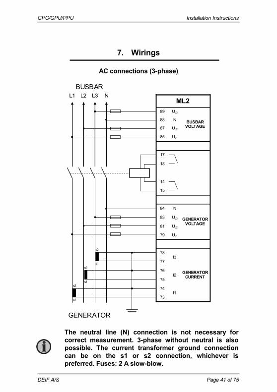
7. Wirings
AC connections (3-phase)
BUSBAR
s1
L1 L2 L3 N
GENERATOR
89 UL3
BUSBAR VOLTAGE
88 N
87 UL2
85 UL1
17
18
14
15
84 N
GENERATOR VOLTAGE
83 UL3
81 UL2
79 UL1
78 I3
GENERATOR CURRENT
77
76 I2
75
74 I1
73
ML2
s1
s1 s2
s2
s2
The neutral line (N) connection is not necessary for correct measurement. 3-phase without neutral is also possible. The current transformer ground connection can be on the s1 or s2 connection, whichever is preferred. Fuses: 2 A slow-blow.
GPC/GPU/PPU Installation Instructions
DEIF A/S Page 42 of 75
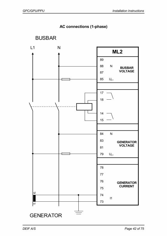
AC connections (1-phase)
BUSBAR
s1
L1 N
GENERATOR
89
BUSBAR VOLTAGE
88 N
87
85 UL1
17
18
14
15
84 N
GENERATOR VOLTAGE
83
81
79 UL1
78
GENERATOR CURRENT
77
76
75
74 I1
73
ML2
s2
GPC/GPU/PPU Installation Instructions
DEIF A/S Page 43 of 75
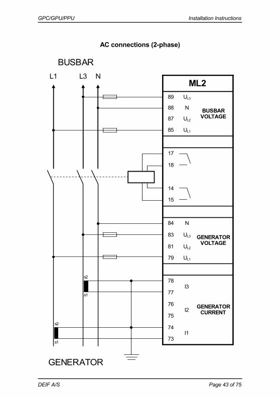
AC connections (2-phase)
BUSBAR
s1
L1 L3 N
GENERATOR
89 UL3
BUSBAR VOLTAGE
88 N
87 UL2
85 UL1
17
18
14
15
84 N
GENERATOR VOLTAGE
83 UL3
81 UL2
79 UL1
78 I3
GENERATOR CURRENT
77
76 I2
75
74 I1
73
ML2
s1
s2
s2
GPC/GPU/PPU Installation Instructions
DEIF A/S Page 44 of 75
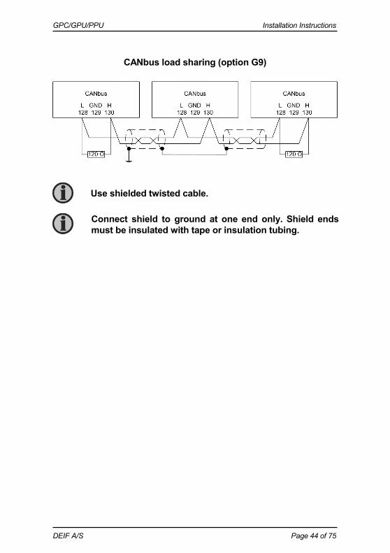
CANbus load sharing (option G9)
Use shielded twisted cable.
Connect shield to ground at one end only. Shield ends must be insulated with tape or insulation tubing.

GPC/GPU/PPU Installation Instructions
DEIF A/S Page 45 of 75
Modbus, RS485 (option H2) Connection with 2-wire screened cable (recommended):
Use shielded twisted cable.
Connect shield to ground at one end only. Shield ends must be insulated with tape or insulation tubing.
Not used
DA
TA - (B
)
CO
M
DA
TA + (A
)
Multi-line
29 30 31 32 33 34 35 36
Not used
Not used
DA
TA + (A
)
DA
TA - (B
)
Not used
DA
TA - (B
)
CO
M
DA
TA + (A
)
Multi-line
29 30 31 32 33 34 35 36
Not used
Not used
DA
TA + (A
)
DA
TA - (B
)
Not used
DA
TA - (B
)
CO
M
DA
TA + (A
)
Multi-line
29 30 31 32 33 34 35 36
Not used
Not used
DA
TA + (A
)
DA
TA - (B
)
PLC or other device
DA
TA -(B
)C
OM
DA
TA + (A
)

GPC/GPU/PPU Installation Instructions
DEIF A/S Page 46 of 75
Connection with 3-wire shielded cable:
Use shielded twisted cable.
Connect shield to ground at one end only. Shield ends must be insulated with tape or insulation tubing.
This solution is only feasible if the COM line is insulated. Check PLC/other device before connecting. A non-insulated COM line may result in damage to the equipment.
PLC or other device
DA
TA -(B
)C
OM
DA
TA + (A
)
Not used
DA
TA - (B
)
CO
M
DA
TA + (A
)
Multi-line
29 30 31 32 33 34 35 36
Not used
Not used
DA
TA + (A
)
DA
TA - (B
)
Not used
DA
TA - (B
)
CO
M
DA
TA + (A
)
Multi-line
29 30 31 32 33 34 35 36
Not used
Not used
DA
TA + (A
)
DA
TA - (B
)
Not used
DA
TA - (B
)
CO
M
DA
TA + (A
)
Multi-line
29 30 31 32 33 34 35 36
Not used
Not used
DA
TA + (A
)
DA
TA - (B
)

GPC/GPU/PPU Installation Instructions
DEIF A/S Page 47 of 75
Cable: Belden 3105 A or equivalent. 22 AWG (0.6 mm2) twisted pair, shielded, <40 m/m, min. 95% shield coverage.
Normally, the Modbus does not need bias resistors (end terminators). These are only needed in case of very long lines and/or many nodes (>32) on the Modbus network. If bias resistors are needed, the calculation should be based on the following data: - A line internal pull-up bias resistor: 22 k - B line internal pull-down bias resistor: 22 k - Receiver input sensitivity: +/-200 mV - Receiver input impedance: 12 k

GPC/GPU/PPU Installation Instructions
DEIF A/S Page 48 of 75
Modbus, RS232 (option H9.2) Connection to an external controller (PLC, PC, etc.) or a modem (GSM or RTC):
External controller or modem
TxD
Gnd
RxD
Multi-line
TxD
GN
D
29 30 31 32 33 34 35 36 > H9.2 option
RxD
Cable: Belden 3106 A or equivalent. 22 AWG (0.6 mm2) shielded, <40 m/m, min. 95% shield coverage.
Connect shield to earth at one end only. Shield ends must be insulated with tape or insulation tubing.
This solution is only feasible if the COM line is insulated. Check PLC/other device before connecting. A non-insulated COM line may result in damage to the equipment.
GPC/GPU/PPU Installation Instructions
DEIF A/S Page 49 of 75
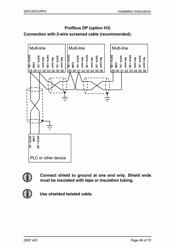
Profibus DP (option H3) Connection with 2-wire screened cable (recommended):
Use shielded twisted cable.
Connect shield to ground at one end only. Shield ends must be insulated with tape or insulation tubing.
Not used
DA
TA - (A
)
CO
M
DA
TA + (B
)
Multi-line 29 30 31 32 33 34 35 36
Not used
Not used
DA
TA + (B
)
DA
TA - (A
)
PLC or other device
DA
TA -(A
)C
OM
DA
TA + (B
)
Not used
DA
TA - (A
)
CO
M
DA
TA + (B
)
Multi-line 29 30 31 32 33 34 35 36
Not used
Not used
DA
TA + (B
)
DA
TA - (A
)
Not used
DA
TA - (A
)
CO
M
DA
TA + (B
)
Multi-line 29 30 31 32 33 34 35 36
Not used
Not used
DA
TA + (B
)
DA
TA - (A
)

GPC/GPU/PPU Installation Instructions
DEIF A/S Page 50 of 75
CANbus engine communication (option H5)
The terminating resistor at the engine side might not be needed, please refer to the engine manufacturer’s litera-ture.
Use shielded twisted cable.
Connect shield to ground at one end only. Shield ends must be insulated with tape or insulation tubing.
End resistor R = 120 Ohm.
Multi-line CAN option H5 131 132 133
CA
N-L
GN
D
CA
N-H
R
Engine Controller
CA
N-L
GN
D
CA
N-H
R

GPC/GPU/PPU Installation Instructions
DEIF A/S Page 51 of 75
CANbus engine communication (option H7)
The terminating resistor at the engine side might not be needed, please refer to the engine manufacturer’s litera-ture.
Use shielded twisted cable.
Connect shield to ground at one end only. Shield ends must be insulated with tape or insulation tubing.
End resistor R = 120 Ohm.
Multi-line CAN option H7 A3 A2 A1
CA
N-L
GN
D
CA
N-H
R
Engine Controller
CA
N-L
GN
D
CA
N-H
R
GPC/GPU/PPU Installation Instructions
DEIF A/S Page 52 of 75
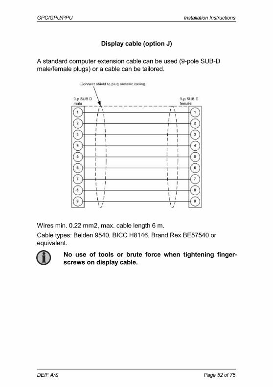
Display cable (option J)
A standard computer extension cable can be used (9-pole SUB-D male/female plugs) or a cable can be tailored.
Wires min. 0.22 mm2, max. cable length 6 m. Cable types: Belden 9540, BICC H8146, Brand Rex BE57540 or equivalent. No use of tools or brute force when tightening finger-
screws on display cable.

GPC/GPU/PPU Installation Instructions
DEIF A/S Page 53 of 75
Load sharing lines Screened, twisted cable is recommended to prevent disturbances on the load sharing lines.
Mechanical speed governor The illustration below shows the necessary connections to carry out speed control using relay outputs.

GPC/GPU/PPU Installation Instructions
DEIF A/S Page 54 of 75
In order to extend the lifetime of the internal relays and prevent unwanted switching noise, it is recommended to use free wheel diodes (1N4007) if a DC voltage is used for the regulation. If an AC voltage is used for the regulation, it is recommended to use a varistor. The diode/varistor must be placed across the terminals of the pilot motor/external regulation relay coil.
AVR with relay outputs
GPC/GPU/PPU Installation Instructions
DEIF A/S Page 55 of 75
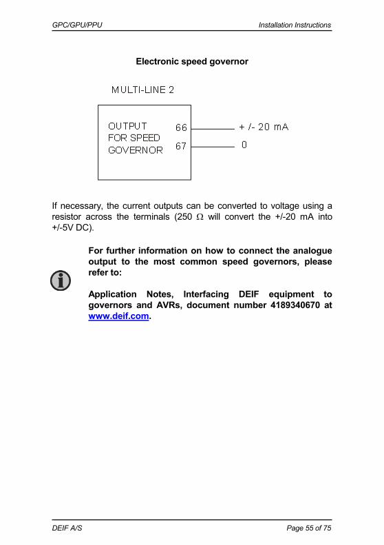
Electronic speed governor If necessary, the current outputs can be converted to voltage using a resistor across the terminals (250 will convert the +/-20 mA into +/-5V DC).
For further information on how to connect the analogue output to the most common speed governors, please refer to: Application Notes, Interfacing DEIF equipment to governors and AVRs, document number 4189340670 at www.deif.com.
GPC/GPU/PPU Installation Instructions
DEIF A/S Page 56 of 75
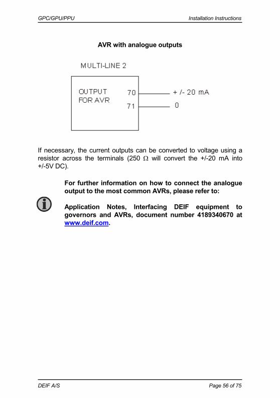
AVR with analogue outputs If necessary, the current outputs can be converted to voltage using a resistor across the terminals (250 will convert the +/-20 mA into +/-5V DC).
For further information on how to connect the analogue output to the most common AVRs, please refer to: Application Notes, Interfacing DEIF equipment to governors and AVRs, document number 4189340670 at www.deif.com.
GPC/GPU/PPU Installation Instructions
DEIF A/S Page 57 of 75
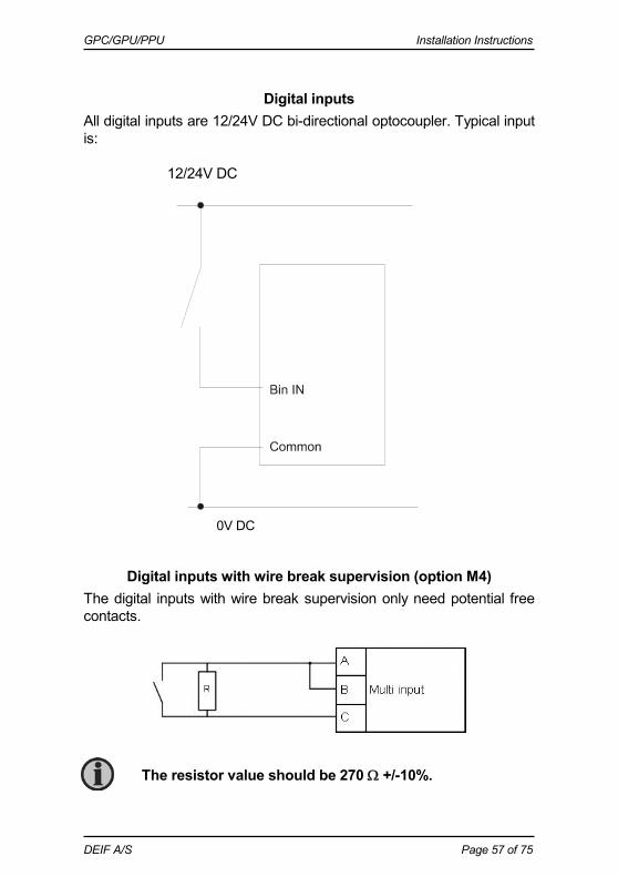
Digital inputs All digital inputs are 12/24V DC bi-directional optocoupler. Typical input is:
12/24V DC
Digital inputs with wire break supervision (option M4) The digital inputs with wire break supervision only need potential free contacts.
0V DC
The resistor value should be 270 +/-10%.

GPC/GPU/PPU Installation Instructions
DEIF A/S Page 58 of 75
Multi-functional inputs (option M4)
0(4)-20 mA Active transducer Passive transducer
If the predefined binary inputs with cable supervision are not used, they can be used for the following.
If the passive sensor has its own battery supply, the voltage must not exceed 30V DC.
+24V DC
0V DC
+24V DC
0V DC
GPC/GPU/PPU Installation Instructions
DEIF A/S Page 59 of 75
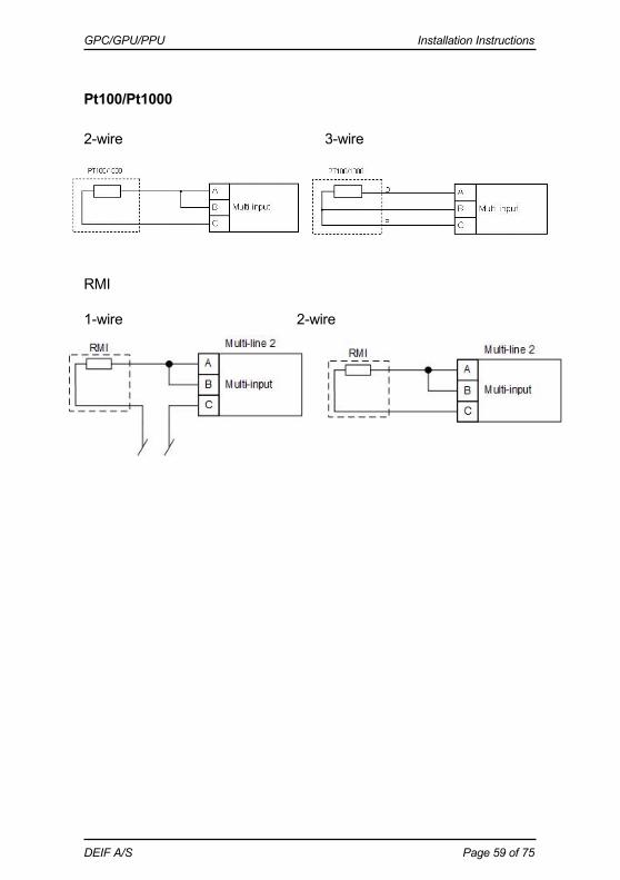
Pt100/Pt1000 2-wire 3-wire
RMI 1-wire 2-wire

GPC/GPU/PPU Installation Instructions
DEIF A/S Page 60 of 75
Magnetic pick-up (MPU) input (option M4)
Magnetic pick-up (MPU)
NPN sensor C = 22 nF, 100 V foil type R = 1200Ω@24V DC, 600Ω@12V DC
PNP sensor C = 22 nF, 100 V foil type R = 1200Ω@24V DC, 600Ω@12V DC
Charger, W output C = 22 nF, 100 V foil type
ML-2
ML-2
ML-2
ML-2
GPC/GPU/PPU Installation Instructions
DEIF A/S Page 61 of 75
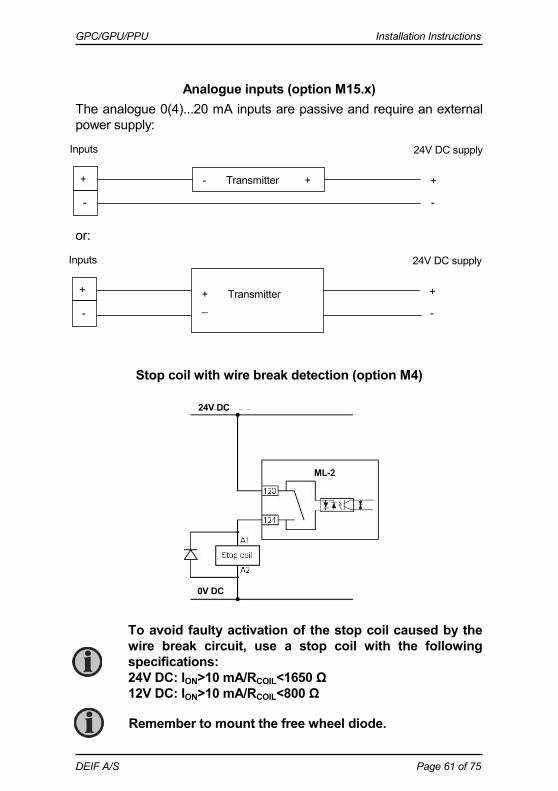
Analogue inputs (option M15.x) The analogue 0(4)...20 mA inputs are passive and require an external power supply: or:
Stop coil with wire break detection (option M4)
+
-
- Transmitter +
Inputs 24V DC supply
+
-
+
-
+ Transmitter _
Inputs 24V DC supply
+
-
Remember to mount the free wheel diode.
0V DC
24V DC
ML-2
To avoid faulty activation of the stop coil caused by the wire break circuit, use a stop coil with the following specifications: 24V DC: ION>10 mA/RCOIL<1650 Ω 12V DC: ION>10 mA/RCOIL<800 Ω

GPC/GPU/PPU Installation Instructions
DEIF A/S Page 62 of 75
Transistor outputs The open collector outputs can be used as kWh and kVArh counter outputs or as relay outputs. The outputs are low power outputs. For that reason one of the following circuits must be applied. External counter: Relay outputs:
Connection to PLC: Remember to mount the free wheel diode.
Max. load: 10 mA.
24V DC
0V DC
ML-2
24V DC
0V DC
ML-2
0V DC
24V DC
ML-2

GPC/GPU/PPU Installation Instructions
DEIF A/S Page 63 of 75
Additional display unit, DU-2 (option X2) End resistor: 2 units connected: Dip switch no. 1 has to be set to ON on both
units. 3 units connected: Dip switch no. 1 has to be set to ON on unit 1
and unit 3.
A DC/DC converter for the DC supply voltage and 2 x 1 m cable with an RJ45 plug in one end and stripped wires in the other end are included in the DU-2 (option X2) delivery.
The maximum length of the CANbus line is 200 m.
GPC/GPU/PPU Installation Instructions
DEIF A/S Page 64 of 75
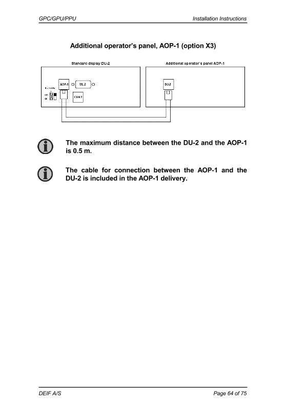
Additional operator’s panel, AOP-1 (option X3)
The maximum distance between the DU-2 and the AOP-1 is 0.5 m.
The cable for connection between the AOP-1 and the DU-2 is included in the AOP-1 delivery.
GPC/GPU/PPU Installation Instructions
DEIF A/S Page 65 of 75
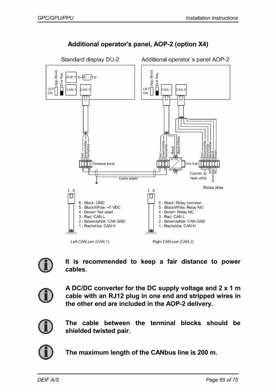
Additional operator's panel, AOP-2 (option X4)
A DC/DC converter for the DC supply voltage and 2 x 1 m cable with an RJ12 plug in one end and stripped wires in the other end are included in the AOP-2 delivery.
The maximum length of the CANbus line is 200 m.
The cable between the terminal blocks should be shielded twisted pair.
It is recommended to keep a fair distance to power cables.
GPC/GPU/PPU Installation Instructions
DEIF A/S Page 66 of 75
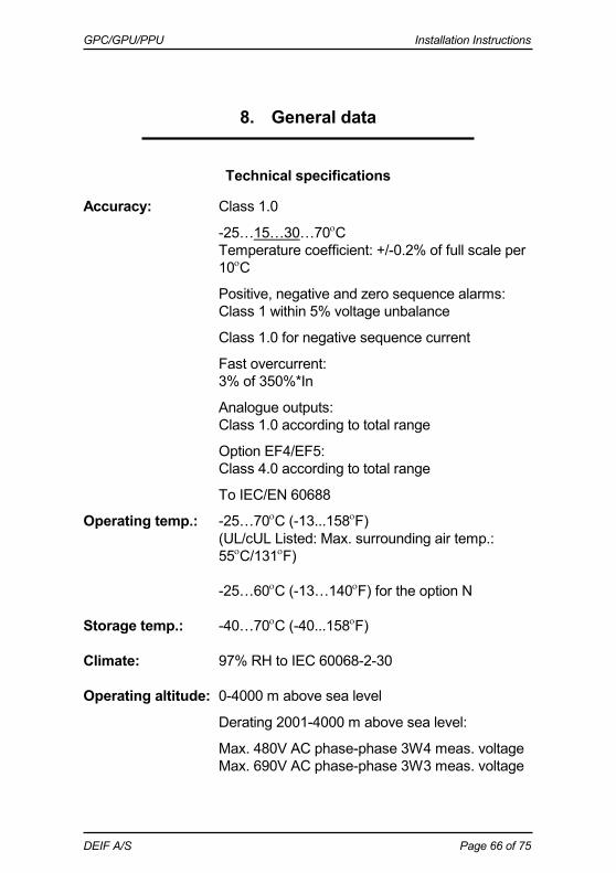
8. General data
Technical specifications
Accuracy: Class 1.0
-25…15…30…70C Temperature coefficient: +/-0.2% of full scale per
10C
Positive, negative and zero sequence alarms: Class 1 within 5% voltage unbalance
Class 1.0 for negative sequence current
Fast overcurrent: 3% of 350%*In
Analogue outputs: Class 1.0 according to total range
Option EF4/EF5: Class 4.0 according to total range
To IEC/EN 60688
Operating temp.: -25…70C (-13...158F) (UL/cUL Listed: Max. surrounding air temp.: 55C/131F) -25…60C (-13…140F) for the option N
Storage temp.: -40…70C (-40...158F) Climate: 97% RH to IEC 60068-2-30 Operating altitude: 0-4000 m above sea level
Derating 2001-4000 m above sea level:
Max. 480V AC phase-phase 3W4 meas. voltage Max. 690V AC phase-phase 3W3 meas. voltage
GPC/GPU/PPU Installation Instructions
DEIF A/S Page 67 of 75
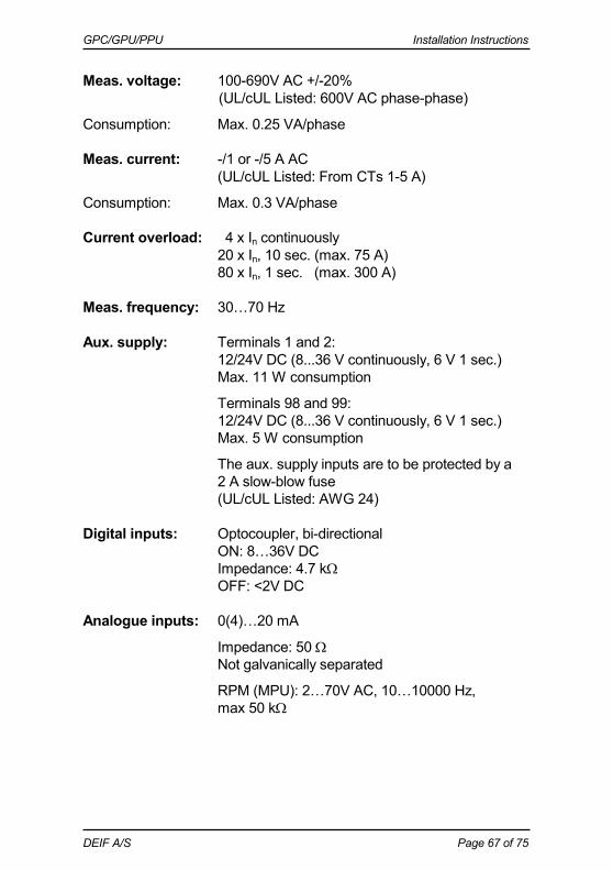
Meas. voltage: 100-690V AC +/-20% (UL/cUL Listed: 600V AC phase-phase)
Consumption: Max. 0.25 VA/phase Meas. current: -/1 or -/5 A AC (UL/cUL Listed: From CTs 1-5 A)
Consumption: Max. 0.3 VA/phase Current overload: 4 x In continuously 20 x In, 10 sec. (max. 75 A) 80 x In, 1 sec. (max. 300 A) Meas. frequency: 30…70 Hz Aux. supply: Terminals 1 and 2: 12/24V DC (8...36 V continuously, 6 V 1 sec.) Max. 11 W consumption
Terminals 98 and 99: 12/24V DC (8...36 V continuously, 6 V 1 sec.) Max. 5 W consumption
The aux. supply inputs are to be protected by a 2 A slow-blow fuse (UL/cUL Listed: AWG 24) Digital inputs: Optocoupler, bi-directional ON: 8…36V DC Impedance: 4.7 k OFF: <2V DC Analogue inputs: 0(4)…20 mA
Impedance: 50 Not galvanically separated
RPM (MPU): 2…70V AC, 10…10000 Hz, max 50 k
GPC/GPU/PPU Installation Instructions
DEIF A/S Page 68 of 75
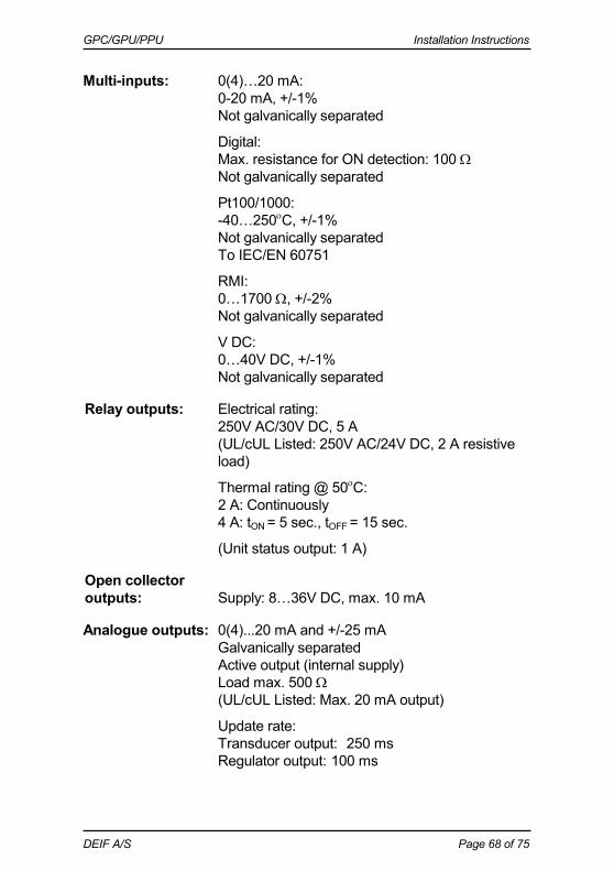
Multi-inputs: 0(4)…20 mA: 0-20 mA, +/-1% Not galvanically separated
Digital: Max. resistance for ON detection: 100
Not galvanically separated
Pt100/1000: -40…250C, +/-1%
Not galvanically separated To IEC/EN 60751
RMI: 0…1700 , +/-2% Not galvanically separated
V DC: 0…40V DC, +/-1% Not galvanically separated
Relay outputs: Electrical rating: 250V AC/30V DC, 5 A
(UL/cUL Listed: 250V AC/24V DC, 2 A resistive load)
Thermal rating @ 50C: 2 A: Continuously 4 A: tON = 5 sec., tOFF = 15 sec.
(Unit status output: 1 A) Open collector outputs: Supply: 8…36V DC, max. 10 mA Analogue outputs: 0(4)...20 mA and +/-25 mA Galvanically separated Active output (internal supply) Load max. 500
(UL/cUL Listed: Max. 20 mA output)
Update rate: Transducer output: 250 ms Regulator output: 100 ms
GPC/GPU/PPU Installation Instructions
DEIF A/S Page 69 of 75
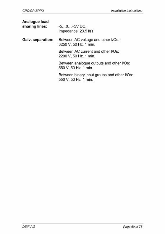
Analogue load sharing lines: -5…0…+5V DC, Impedance: 23.5 k Galv. separation: Between AC voltage and other I/Os: 3250 V, 50 Hz, 1 min.
Between AC current and other I/Os: 2200 V, 50 Hz, 1 min.
Between analogue outputs and other I/Os: 550 V, 50 Hz, 1 min.
Between binary input groups and other I/Os: 550 V, 50 Hz, 1 min.

GPC/GPU/PPU Installation Instructions
DEIF A/S Page 70 of 75
Response times: (Delay set to minimum)
Busbar: Over-/undervoltage: <50 ms Over-/underfrequency: <50 ms Voltage unbalance: <200 ms
Generator: Reverse power: <200 ms Overcurrent: <200 ms Fast overcurrent: <40 ms Over-/undervoltage: <200 ms Over-/underfrequency: <300 ms Overload: <200 ms Current unbalance: <200 ms Voltage unbalance: <200 ms React. power import: <200 ms React. power export: <200 ms Overspeed: <400 ms Digital inputs: <250 ms Emergency stop: <200 ms Multi-inputs: <800 ms Wire failure: <600 ms
Mains: df/dt (ROCOF): <130 ms (4 periods) Vector jump: < 40 ms Positive sequence: < 60 ms Time-dependent undervoltage, Ut< < 50 ms Undervoltage and re- active power low, UQ< <250 ms Mounting: DIN rail mount or base mount with 6 screws Safety: To EN 61010-1, installation category
(overvoltage category) III, 600 V, pollution degree 2
To UL 508 and CSA 22.2 no. 14-05, overvoltage category III, 600 V, pollution degree 2
GPC/GPU/PPU Installation Instructions
DEIF A/S Page 71 of 75
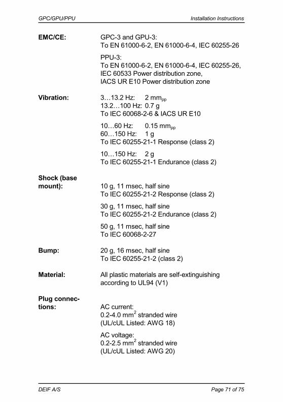
EMC/CE: GPC-3 and GPU-3: To EN 61000-6-2, EN 61000-6-4, IEC 60255-26
PPU-3: To EN 61000-6-2, EN 61000-6-4, IEC 60255-26, IEC 60533 Power distribution zone, IACS UR E10 Power distribution zone Vibration: 3…13.2 Hz: 2 mmpp 13.2…100 Hz: 0.7 g To IEC 60068-2-6 & IACS UR E10
10…60 Hz: 0.15 mmpp 60…150 Hz: 1 g To IEC 60255-21-1 Response (class 2)
10…150 Hz: 2 g To IEC 60255-21-1 Endurance (class 2) Shock (base mount): 10 g, 11 msec, half sine To IEC 60255-21-2 Response (class 2)
30 g, 11 msec, half sine To IEC 60255-21-2 Endurance (class 2)
50 g, 11 msec, half sine To IEC 60068-2-27 Bump: 20 g, 16 msec, half sine To IEC 60255-21-2 (class 2) Material: All plastic materials are self-extinguishing
according to UL94 (V1) Plug connec- tions: AC current: 0.2-4.0 mm2 stranded wire (UL/cUL Listed: AWG 18)
AC voltage: 0.2-2.5 mm2 stranded wire (UL/cUL Listed: AWG 20)
GPC/GPU/PPU Installation Instructions
DEIF A/S Page 72 of 75
Relays: (UL/cUL Listed: AWG 22)
Terminals 98-116: 0.2-1.5 mm2 stranded wire (UL/cUL Listed: AWG 24)
Other: 0.2-2.5 mm2 stranded wire (UL/cUL Listed: AWG 24)
Display: 9-pole Sub-D female
Service port: USB A-B Protection: Unit: IP20
Display: IP52 (IP54 with gasket: Option L) (UL/cUL Listed: Type Complete Device, Open
Type)
To IEC/EN 60529 Governors: Multi-line 2 interfaces to all governors, including
GAC, Barber-Colman, Woodward and Cummins
See interfacing guide at www.deif.com Approvals: Marine approved by all major classification
societies UL/cUL Listed to UL508 UL/cUL Recognized to UL2200 UL markings: Wiring: Use 60/75C copper conductors only
Mounting: For use on a flat surface of type 1 enclosure
Installation: To be installed in accordance with the NEC (US)
or the CEC (Canada)

GPC/GPU/PPU Installation Instructions
DEIF A/S Page 73 of 75
AOP-2: Maximum ambient temperature: 60C
Wiring: Use 60/75C copper conductors only
Mounting: For use on a flat surface of type 3 (IP54)
enclosure Main disconnect must be provided by installer
Installation: To be installed in accordance with the NEC (US)
or the CEC (Canada) DC/DC converter for AOP-2: Tightening torque: 0.5 Nm (4.4 lb-in)
Wire size: AWG 22-14 Weight: Base unit: 1.6 kg (3.5 lbs.) Option J1/J3/J6: 0.2 kg (0.4 lbs.) Option J2: 0.4 kg (0.9 lbs.) Display: 0.4 kg (0.9 lbs.)

GPC/GPU/PPU Installation Instructions
DEIF A/S Page 74 of 75
Dimensions
Unit
Dimensions are given in mm (inches).

GPC/GPU/PPU Installation Instructions
DEIF A/S Page 75 of 75
Panel cutout
Drilling template
DEIF A/S reserves the right to change any of the above.
Dimensions are given in mm (inches).