ml200 installation and commissioning guide
TRANSCRIPT
8/19/2019 Ml200 Installation and Commissioning Guide
http://slidepdf.com/reader/full/ml200-installation-and-commissioning-guide 1/92
ML200 Installation andCommissioning Guide
R210
November 2011
Release 210
Honeywell Confi dential & Proprietary
This work contains valuable, confidential and proprietary information. Disclosure, use orreproduction outside of Honeywell International Inc. is prohibited except as authorized in writing.This unpublished work is protected by the laws of the United States and other countries.

8/19/2019 Ml200 Installation and Commissioning Guide
http://slidepdf.com/reader/full/ml200-installation-and-commissioning-guide 2/92
ii ML200 Installation and Commissioning Guide R210Honeywell Confidential & Proprietary November 2011
Notices and Trademarks
Copyright 2010 by Honeywell International Sárl.Release 210 November 2011
While this information is presented in good faith and believed to be accurate, Honeywell disclaimsthe implied warranties of merchantability and fitness for a particular purpose and makes noexpress warranties except as may be stated in its written agreement with and for its customers.
In no event is Honeywell liable to anyone for any indirect, special or consequential damages. Theinformation and specifications in this document are subject to change without notice.
Honeywell, PlantScape, Experion PKS, and TotalPlant are registered trademarks of HoneywellInternational Inc.
Other brand or product names are trademarks of their respective owners.
Honeywell Process Solutions
1860 W. Rose Garden Lane
Phoenix, AZ 85027 USA
1-800 822-7673
8/19/2019 Ml200 Installation and Commissioning Guide
http://slidepdf.com/reader/full/ml200-installation-and-commissioning-guide 3/92
R210 ML200 Installation and Commissioning Guide iiiNovember 2011 Honeywell Confidential & Proprietary
About This Document
This document describes the Installation and Powering On procedure for Master Logic200 PLCs and its associated modules.
Release Information
Document Name DocumentID
ReleaseNumber
PublicationDate
ML200 Installation and Commissioning Guide 210 November2011

8/19/2019 Ml200 Installation and Commissioning Guide
http://slidepdf.com/reader/full/ml200-installation-and-commissioning-guide 4/92
Acronyms and Definitions
iv ML200 Installation and Commissioning Guide R210Honeywell Confidential & Proprietary November 2011
Acronyms and Defini tions
Acr on ym/Term Defini tion
BaseThe back plane of the PLC on which the power supply,communication, and other modules are installed.Examples: Main base and expansion base.
CPU Central Processing Unit
Dnet DeviceNet Interface
FEnet Fast Ethernet Network
FO Fiber-Optic
I/O Input/Output
IEC International Electrotechnical Commission
ML MasterLogic
Module
A standard component with a specific function to configurea system, such as the I/O board assembled that must beinserted into the base motherboard.
Examples: CPU module, power module, and I/O module.
PLC Programmable Logic Controller
PLC System A system consisting of a PLC, CPU, modules andperipherals configured to be controlled by a user program.
Pnet Profibus-DP Network.
PSU Power Supply Unit
RAM Random Access Memory
Snet Serial Link Network
SoftMaster Programming tool for creating, editing, and debugging aprogram.
STP Shielded Twisted Pair
TP Twisted Pair cables (typically CAT5 cables with RJ45connectors for Ethernet communication.)
UTP Unshield Twisted Pair

8/19/2019 Ml200 Installation and Commissioning Guide
http://slidepdf.com/reader/full/ml200-installation-and-commissioning-guide 5/92
Support and Other Contacts
R210 ML200 Installation and Commissioning Guide vNovember 2011 Honeywell Confidential & Proprietary
Support and Other Contacts
United States and Canada
Contact:Phone:
Fascimile:Mail:
Honeywell Solution Support Center1-800-822-7673Calls are answered by dispatcher between 6:00 am and 4:00 pmMountain Standard Time. Emergency calls outside normal working hoursare received by an answering service and returned within one hour.1-973-455-5000Honeywell TAC, MS L17
1860 W. Garden LanePhoenix, AZ, 85027 USA
Europe, Middle East, and Africa (EMEA)
Contact:Phone:Fascimile:Mail:
Honeywell TAC-EMEA+32-2-728-2345+32-2-728-2696TAC-BE02Hermes PlazaHermeslaan, 1HB-1831 Diegem, Belgium
Pacific
Contact:Phone:
Fascimile:Mail:
Email:
Honeywell Global TAC – Pacific1300-364-822 (toll free within Australia)+61-8-9362-9559 (outside Australia)+61-8-9362-9564Honeywell Limited Australia5 Kitchener WayBurswood 6100, Western [email protected]
India
Contact:Phone:Fascimile:Mail:
Email:
Honeywell Global TAC – India+91-20- 6603-9400+91-20- 6603-9800Honeywell Automation India Ltd56 and 57, Hadapsar Industrial EstateHadapsar, Pune –411 013, [email protected]

8/19/2019 Ml200 Installation and Commissioning Guide
http://slidepdf.com/reader/full/ml200-installation-and-commissioning-guide 6/92
Support and Other Contacts
vi ML200 Installation and Commissioning Guide R210Honeywell Confidential & Proprietary November 2011
Korea
Contact:Phone:Fascimile:Mail:
Email:
Honeywell Global TAC – Korea+82-2-799-6317+82-2-792-9015Honeywell Co., Ltd4F, Sangam IT Tower1590, DMC Sangam-dong, Mapo-guSeoul, 121-836, [email protected]
People’s Republic o f China
Contact:Phone:
Mail:
Email:
Honeywell Global TAC – China+86- 21-2219-6888800-820-0237400-820-0386Honeywell (China) Co., Ltd33/F, Tower A, City Center, 100 Zunyi Rd.Shanghai 200051, People’s Republic of [email protected]
Singapore
Contact:Phone:Fascimile:
Mail:
Email:
Honeywell Global TAC – South East Asia+65-6580-3500+65-6580-3501
+65-6445-3033Honeywell Private LimitedHoneywell Building17, Changi Business Park Central 1Singapore [email protected]
Taiwan
Contact:Phone:Fascimile:Mail:
Email:
Honeywell Global TAC – Taiwan+886-7-536-2567+886-7-536-2039Honeywell Taiwan Ltd.17F-1, No. 260, Jhongshan 2nd Road.Cianjhen DistrictKaohsiung, Taiwan, [email protected]

8/19/2019 Ml200 Installation and Commissioning Guide
http://slidepdf.com/reader/full/ml200-installation-and-commissioning-guide 7/92
Support and Other Contacts
R210 ML200 Installation and Commissioning Guide viiNovember 2011 Honeywell Confidential & Proprietary
Japan
Contact:Phone:Fascimile:Mail:
Email:
Honeywell Global TAC – Japan+81-3-6730-7160+81-3-6730-7228Honeywell Japan Inc.New Pier Takeshiba, South Tower Building,20th Floor, 1-16-1 Kaigan, Minato-ku,Tokyo 105-0022, [email protected]
Elsewhere
Call your nearest Honeywell office.
World Wide Web
Honeywell Solution Support Online:
http://www.honeywell.com/ps
Training Classes
Honeywell Automation College:
http://www.automationcollege.com
8/19/2019 Ml200 Installation and Commissioning Guide
http://slidepdf.com/reader/full/ml200-installation-and-commissioning-guide 8/92
Symbol Definitions
viii ML200 Installation and Commissioning Guide R210Honeywell Confidential & Proprietary November 2011
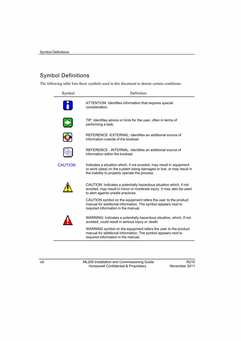
Symbol DefinitionsThe following table lists those symbols used in this document to denote certain conditions.
Symbol Definition
ATTENTION: Identifies information that requires specialconsideration.
TIP: Identifies advice or hints for the user, often in terms ofperforming a task.
REFERENCE -EXTERNAL: Identifies an additional source ofinformation outside of the bookset.
REFERENCE - INTERNAL: Identifies an additional source ofinformation within the bookset.
CAUTION Indicates a situation which, if not avoided, may result in equipmentor work (data) on the system being damaged or lost, or may result inthe inability to properly operate the process.
CAUTION : Indicates a potentially hazardous situation which, if notavoided, may result in minor or moderate injury. It may also be usedto alert against unsafe practices.
CAUTION symbol on the equipment refers the user to the productmanual for additional information. The symbol appears next torequired information in the manual.
WARNING : Indicates a potentially hazardous situation, which, if notavoided, could result in serious injury or death.
WARNING symbol on the equipment refers the user to the productmanual for additional information. The symbol appears next torequired information in the manual.

8/19/2019 Ml200 Installation and Commissioning Guide
http://slidepdf.com/reader/full/ml200-installation-and-commissioning-guide 9/92
Symbol Definitions
R210 ML200 Installation and Commissioning Guide ixNovember 2011 Honeywell Confidential & Proprietary
Symbol Definition
WARNING, Risk of electrical sho ck : Potential shock hazard whereHAZARDOUS LIVE voltages greater than 30 Vrms, 42.4 Vpeak, or60 VDC may be accessible.
ESD HAZARD: Danger of an electro-static discharge to whichequipment may be sensitive. Observe precautions for handlingelectrostatic sensitive devices.
Protective Earth (PE) terminal : Provided for connection of the
protective earth (green or green/yellow) supply system conductor.
Functional earth terminal : Used for non-safety purposes such asnoise immunity improvement. NOTE: This connection shall bebonded to Protective Earth at the source of supply in accordancewith national local electrical code requirements.
Earth Ground : Functional earth conn ection. NOTE: Thisconnection shall be bonded to Protective Earth at the source ofsupply in accordance with national and local electrical coderequirements.
Chassis Ground : Identifies a connection to the chassis or frame ofthe equipment shall be bonded to Protective Earth at the source ofsupply in accordance with national and local electrical coderequirements.

8/19/2019 Ml200 Installation and Commissioning Guide
http://slidepdf.com/reader/full/ml200-installation-and-commissioning-guide 10/92
Symbol Definitions
x ML200 Installation and Commissioning Guide R210Honeywell Confidential & Proprietary November 2011

8/19/2019 Ml200 Installation and Commissioning Guide
http://slidepdf.com/reader/full/ml200-installation-and-commissioning-guide 11/92
R210 ML200 Installation and Commissioning Guide xiNovember 2011 Honeywell Confidential & Proprietary
Contents
1. MASTERLOGIC COMPONENTS ................................................. 15
1.1 Types of CPUs ............................................................................................... 15
1.2 Types of power supply ................................................................................. 16 Power supplies for ML200-IEC ............................................................................................. 16 Power supplies for ML200R ................................................................................................. 18
1.3 Types of modules .......................................................................................... 21 Input/Output module ............................................................................................................. 21 Special module ..................................................................................................................... 22 Communication module ....................................................................................................... 23
1.4 Types of base ................................................................................................ 24 ML200-IEC Main base ......................................................................................................... 24 ML200-IEC Expansion base................................................................................................. 25 ML200R Main base .............................................................................................................. 26 ML200R Expansion base ..................................................................................................... 28
1.5 Types of cables ............................................................................................. 32 Cables for ML200-IEC .......................................................................................................... 32 Cables for ML200R .............................................................................................................. 32 Optical cables ....................................................................................................................... 33 Ethernet cables .................................................................................................................... 33
2. CALCULATING THE POWER SUPPLY FOR COMPONENTS ... 37
2.1 Power module specif ications ....................................................................... 37
2.2 Select ing t he Power supp ly ......................................................................... 39 Example of current consumption/power calculations for ML200-IEC ................................... 39 Example of current consumption/power calculations for ML200R ........................................ 40 Power consumption of each part .......................................................................................... 42
3. PLAN AND INSTALL MLPLC ...................................................... 45
3.1 Plan fo r Engi neeri ng Stati on ........................................................................ 45 Platform requirements .......................................................................................................... 45 Prerequisites for Installation ................................................................................................. 45 Grounding requirements ...................................................................................................... 50 Precautions for installing/handling the PLC modules ........................................................... 51
3.2 Mount ing Chass is ......................................................................................... 53
8/19/2019 Ml200 Installation and Commissioning Guide
http://slidepdf.com/reader/full/ml200-installation-and-commissioning-guide 12/92
ContentsSymbol Definitions
xii ML200 Installation and Commissioning Guide R210Honeywell Confidential & Proprietary November 2011
Cabinet mounting ................................................................................................................ 53
3.3 Achi evi ng th e to po logy ...................... .................. .................. .................. ..... 57 Achieving the topology for ML200-IEC ................................................................................ 57 Achieving the topology for ML200R ..................................................................................... 61
3.4 Power on and st art up ................................................................................... 70 I/O device wiring .................................................................................................................. 70 Power wiring ........................................................................................................................ 71 Module LEDs ....................................................................................................................... 73 Module state transition ........................................................................................................ 76 Starting the system .............................................................................................................. 77
4. TROUBLESHOOTING ................................................................. 79 4.1 Overview ......................................................................................................... 79
4.2 Basic troubleshooting procedure ................................................................ 79
4.3 Cases and remedies f or fai lu res .................................................................. 80 Trouble types and measures of input circuit ........................................................................ 80 Trouble types and measures of output circuit ...................................................................... 81 Error codes list .................................................................................................................... 84

8/19/2019 Ml200 Installation and Commissioning Guide
http://slidepdf.com/reader/full/ml200-installation-and-commissioning-guide 13/92
ContentsTables
R210 ML200 Installation and Commissioning Guide xiiiNovember 2011 Honeywell Confidential & Proprietary
TablesTable 1-1 Power modules for ML200-IEC ..................................................................... 16Table 1-2 Specifications of the power modules for ML200-IEC .................................... 16Table 1-3 Power modules for ML200R .......................................................................... 19Table 1-4 Specifications of the power modules for ML200R ......................................... 19Table 1-5 Types of I/O modules .................................................................................... 21Table 1-6 Types of special modules .............................................................................. 22Table 1-7 Types of communication modules ................................................................. 23Table 1-8 Types of bases for ML200-IEC ...................................................................... 24Table 1-9 Types of expansion bases for ML200-IEC .................................................... 25Table 1-10 Types of bases for ML200R ........................................................................ 26
Table 1-11 Expansion base and expansion driver module for ML200R ....................... 29Table 1-12 Expansion base and expansion driver module for ML200R (with dual IO linkredundancy) ............................................................................................................ 30
Table 1-13 Types of twisted pair ................................................................................... 33Table 2-1 Power specifications ...................................................................................... 37Table 3-1 System requirements .................................................................................... 45Table 3-2 ML200-IEC Dip switch setting ...................................................................... 60Table 3-3 Topology of ML200R ..................................................................................... 66Table 3-4 ML200R Dip switch settings .......................................................................... 69Table 3-5 LED indicators for ML200-IEC ....................................................................... 73Table 3-6 LED indicators for ML200R ........................................................................... 75

8/19/2019 Ml200 Installation and Commissioning Guide
http://slidepdf.com/reader/full/ml200-installation-and-commissioning-guide 14/92
ContentsFigures
xiv ML200 Installation and Commissioning Guide R210Honeywell Confidential & Proprietary November 2011
FiguresFigure 1-1 Main base of ML200-IEC .............................................................................. 24Figure 1-2 Expansion base of ML200-IEC ..................................................................... 26Figure 1-3 Main base of 2MLR-M02P ............................................................................ 27Figure 1-4 Main base of 2MLR-M06P ............................................................................ 28Figure 1-5 Expansion base of ML200R (without dual I/O link redundancy) ................... 29Figure 1-6 Expansion base of ML200R (with dual I/O link redundancy) ........................ 31Figure 1-7 Expansion cable connection for ML200 IEC ................................................ 32Figure 1-8 MMF (LC Type) optical cable ....................................................................... 33Figure 1-9 Cross sections of the twisted pair cables ..................................................... 34Figure 1-10 FTP and STP cables ................................................................................... 35
Figure 3-1 Terminal block wiring .................................................................................... 52Figure 3-2 Inserting a module ........................................................................................ 54Figure 3-3 Removing modules ....................................................................................... 57Figure 3-4 ML200-IEC Architecture ............................................................................... 58Figure 3-5 Installation point of terminating resistor ........................................................ 60Figure 3-6 ML200R architecture without dual I/O link redundancy ................................ 64Figure 3-7 ML200R architecture with dual I/O link redundancy ..................................... 65

8/19/2019 Ml200 Installation and Commissioning Guide
http://slidepdf.com/reader/full/ml200-installation-and-commissioning-guide 15/92
R210 ML200 Installation and Commissioning Guide 15November 2011 Honeywell Confidential & Proprietary
1. Masterlogic components
1.1 Types of CPUsThe following are the types of CPU for MasterLogic-200 PLC system.
• Non redundant PLCs
− 2MLI-CPUU
− 2MLI-CPUH
− 2MLI-CPUS
• Redundant PLC
− 2MLR-CPUH/T
− 2MLR-CPUH/F
The following naming convention is used across the document.
• 2MLI-CPUU, 2MLI-CPUH, and 2MLI-CPUS are represented as ML200-IEC.
• 2MLR-CPUH/T and 2MLR-CPUH/ F are represented as ML200R.

8/19/2019 Ml200 Installation and Commissioning Guide
http://slidepdf.com/reader/full/ml200-installation-and-commissioning-guide 16/92
1. Masterlogic components1.2. Types of power supply
16 ML200 Installation and Commissioning Guide R210Honeywell Confidential & Proprietary November 2011
1.2 Types of power supplyThe different types of voltages supported by ML200-IEC and ML200R are as follows:
• AC 110 V
• AC 220 V
• DC 24V
Power supplies for ML200-IEC
The following table provides the types of power modules for ML200-IEC.
Table 1-1 Power modules for ML200-IEC
Model number Specificatio n
2MLP-ACF1 Free Voltage(AC 110V,220V) / DC5V,3A, DC24V,0.6A
2MLP-ACF2 Free Voltage(AC 110V,220V) / DC5V, 6A
2MLP-AC23 AC 220V / DC 5V, 8.5A
2MLP-DC42 DC 24V / DC 5V
The following table lists the specifications of the power modules for ML200-IEC.
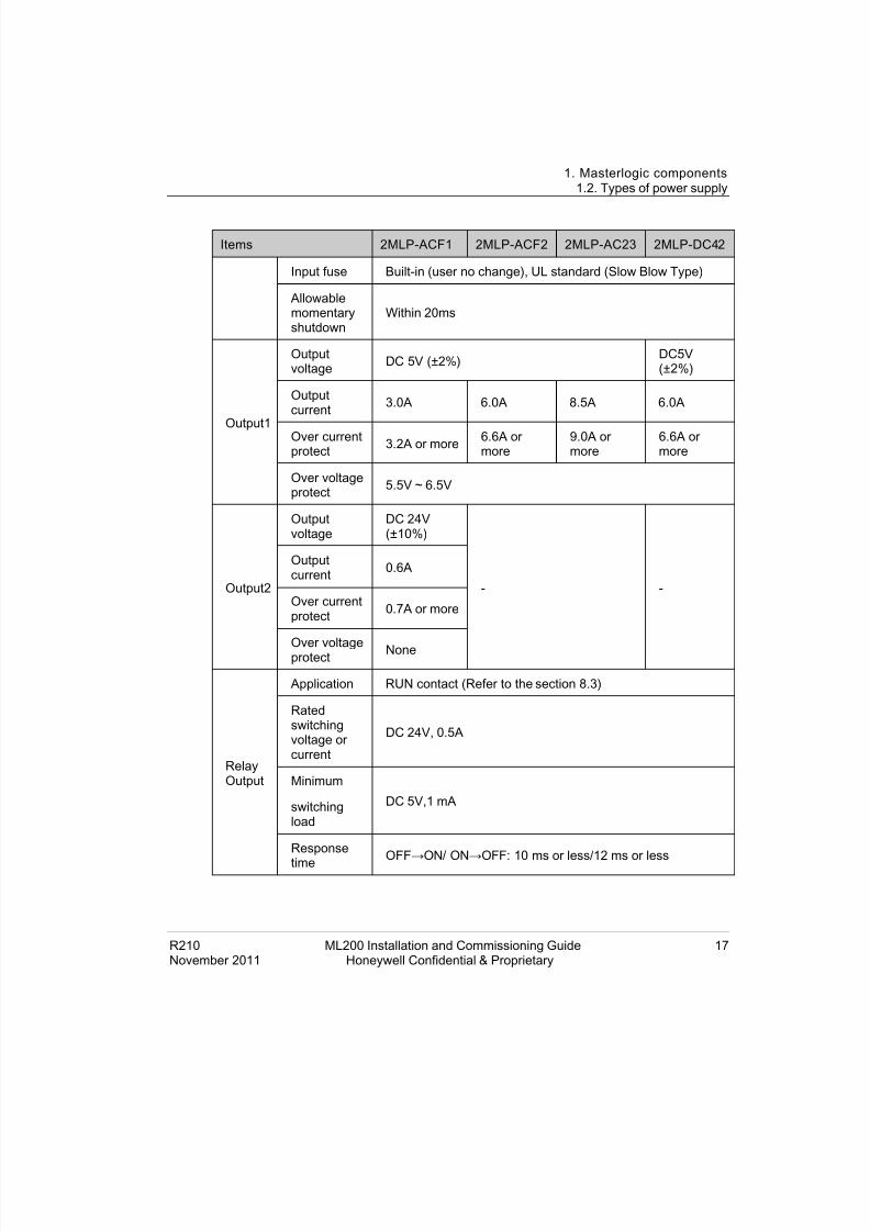
Table 1-2 Specification s o f t he power m odules f or ML200-IEC
Items 2MLP-ACF1 2MLP-ACF2 2MLP-AC23 2MLP-DC42
Input
Rated inputvoltage AC 100V – AC 240V AC 200V –
AC 240V DC 24V
Input voltagerange AC 85V ~ AC 264V AC 170V ~
AC 264V -
Inputfrequency 50 / 60 Hz (47 ~ 63 Hz) -
Inrushcurrent 20 A peak or less 80A peak orless
Efficiency 65% or more 60% ormore
8/19/2019 Ml200 Installation and Commissioning Guide
http://slidepdf.com/reader/full/ml200-installation-and-commissioning-guide 17/92
1. Masterlogic components1.2. Types of power supply
R210 ML200 Installation and Commissioning Guide 17November 2011 Honeywell Confidential & Proprietary
Items 2MLP-ACF1 2MLP-ACF2 2MLP-AC23 2MLP-DC42
Input fuse Built-in (user no change), UL standard (Slow Blow Type)
Allowablemomentaryshutdown
Within 20ms
Output1
Outputvoltage DC 5V (±2%) DC5V
(±2%)
Outputcurrent 3.0A 6.0A 8.5A 6.0A
Over currentprotect 3.2A or more 6.6A or
more9.0A ormore
6.6A ormore
Over voltageprotect 5.5V ~ 6.5V
Output2
Outputvoltage
DC 24V(±10%)
- -
Outputcurrent 0.6A
Over currentprotect 0.7A or more
Over voltageprotect None
RelayOutput
Application RUN contact (Refer to the section 8.3)
Ratedswitchingvoltage orcurrent
DC 24V, 0.5A
Minimum
switchingload
DC 5V,1 mA
Response
timeOFF →ON/ ON→OFF: 10ms or less/12 ms or less

8/19/2019 Ml200 Installation and Commissioning Guide
http://slidepdf.com/reader/full/ml200-installation-and-commissioning-guide 18/92
1. Masterlogic components1.2. Types of power supply
18 ML200 Installation and Commissioning Guide R210Honeywell Confidential & Proprietary November 2011
Items 2MLP-ACF1 2MLP-ACF2 2MLP-AC23 2MLP-DC42
Life
Mechanical: More than 20,000,000 times
Electrical: More than 100,000 times at rated switchingvoltage/current
RUN signal output Relay output, Rating: DC24V, 0.5A
Voltage indicator Output voltage normal, LED ON
Cable specification 0.75 ~ 2mm 2
Compressed terminal RAV 1.25 - 3.5, RAV 2 - 3.5
Weight 0.4kg 0.6kg 0.5kg
ATTENTION
1. Allowable Momentary Power Failure Time: The time that input voltagekeeps normal output voltage (normal operation) in the state that AC110/220V voltage is lower than the rated value (AC85 / 170V).
2. Over current protection: If the current is more than the standard andflows in DC 5V, DC 24V circuit, the over current protection device shutsdown the circuit to stop the system. Remove the causes such as lack ofcurrent capacity or short circuits that leads to over current and thenrestart the system.
3. Over voltage protection: The over voltage protection device shuts downthe circuit to stop the system, if the voltage is greater than the standardand is applied to the DC 5V circuit
Power suppli es for ML200R
ATTENTION
The main reason for using redundant power supply is that it has a componentand the CPU checks this component for its power failure status. Thiscomponent is not available in the non-redundant power supply.
The following table provides the specifications of the power modules for ML200R.

8/19/2019 Ml200 Installation and Commissioning Guide
http://slidepdf.com/reader/full/ml200-installation-and-commissioning-guide 19/92
1. Masterlogic components1.2. Types of power supply
R210 ML200 Installation and Commissioning Guide 19November 2011 Honeywell Confidential & Proprietary
Table 1-3 Power modul es for ML200R
Model number Specification
2MLR-AC12 Redundant power AC 110V, 5.5A
2MLR-AC22 Redundant power AC 220V, 5.5A
2MLR-AC13 Redundant power AC 110V, 8.5A
2MLR-AC23 Redundant power AC 220V, 8.5A
2MLR-DC42 Redundant power DC 24V, 7.5A
The following table lists the specifications of the power modules for ML200R.
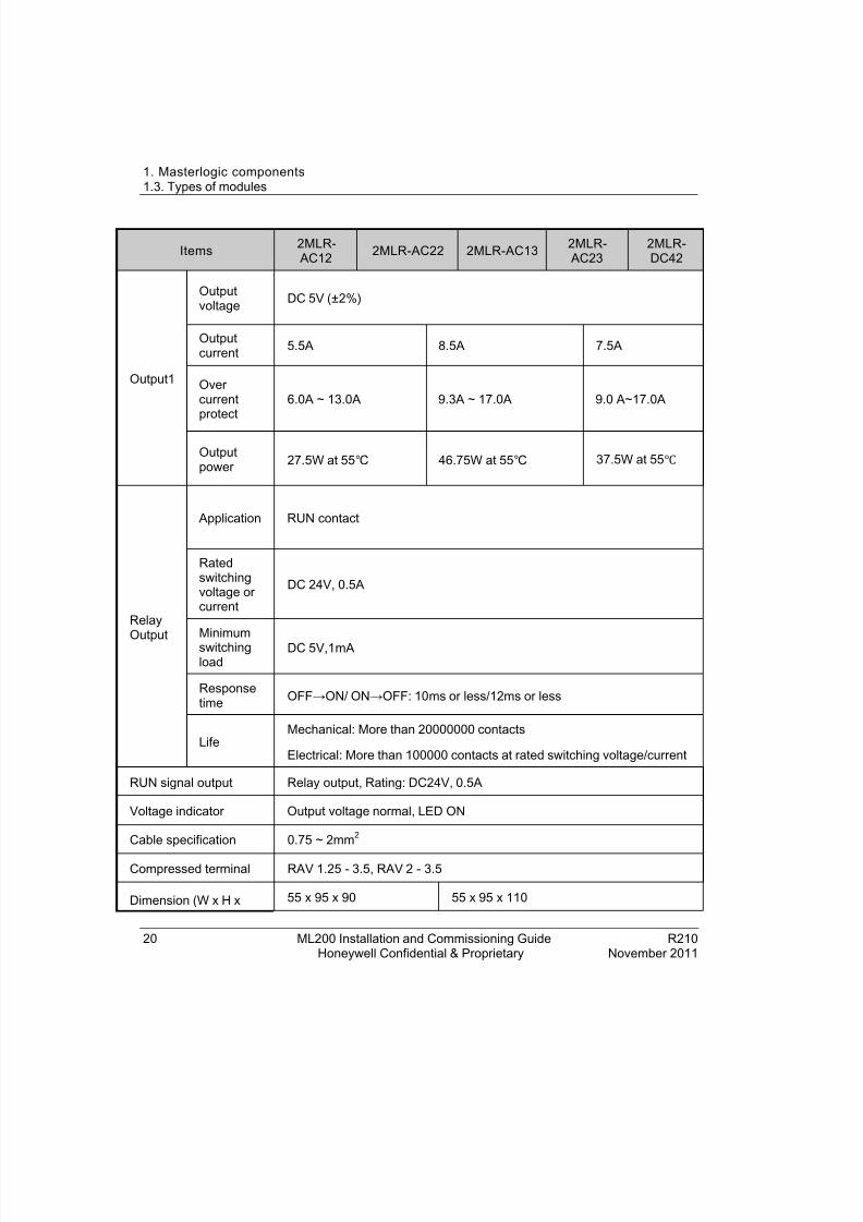
Table 1-4 Specification s of the pow er modules fo r ML200R
Items 2MLR- AC12 2MLR-AC22 2MLR-AC13 2MLR-
AC232MLR-DC42
Input
Rated inputvoltage AC 110V AC 220V AC 110V AC 220V DC24V
Inputvoltagerange
AC 85V ~ AC 132V
AC 176V ~ AC 264V
85V~132V AC
176V~264V AC
19.2~28.8V DC
Inputfrequency 50 / 60 Hz (47 ~ 63Hz) -
Maximuminput power 110VA/42W 176VA/72W -
Inrushcurrent 20 A peak or less (below 8ms) 80A peak
or lower
Efficiency 65% or more
Input fuse Built-in (not replaceable) : AC 250V/3.15A, UL standard (Time-lag Type)and DC power: 125V/10A (Time-lag type), UL-approved
Allowablemomentaryshutdown
Within 20ms
8/19/2019 Ml200 Installation and Commissioning Guide
http://slidepdf.com/reader/full/ml200-installation-and-commissioning-guide 20/92
1. Masterlogic components1.3. Types of modules
20 ML200 Installation and Commissioning Guide R210Honeywell Confidential & Proprietary November 2011
Items 2MLR- AC12 2MLR-AC22 2MLR-AC13 2MLR-
AC232MLR-DC42
Output1
Outputvoltage DC 5V (±2%)
Outputcurrent 5.5A 8.5A 7.5A
Overcurrentprotect
6.0A ~ 13.0A 9.3A ~ 17.0A 9.0 A~17.0A
Outputpower 27.5W at 55 46.75W at 55 37.5W at 55
RelayOutput
Application RUN contact
Ratedswitchingvoltage orcurrent
DC 24V, 0.5A
Minimumswitchingload
DC 5V,1 mA
Responsetime OFF →ON/ ON→OFF: 10ms or less/12 ms or less
LifeMechanical: More than 20000000 contacts
Electrical: More than 100000 contacts at rated switching voltage/current
RUN signal output Relay output, Rating: DC24V, 0.5A
Voltage indicator Output voltage normal, LED ON
Cable specification 0.75 ~ 2mm 2
Compressed terminal RAV 1.25 - 3.5, RAV 2 - 3.5
Dimension (W x H x 55 x 95 x 90 55 x 95 x 110

8/19/2019 Ml200 Installation and Commissioning Guide
http://slidepdf.com/reader/full/ml200-installation-and-commissioning-guide 21/92
1. Masterlogic components1.3. Types of modules
R210 ML200 Installation and Commissioning Guide 21November 2011 Honeywell Confidential & Proprietary
Items 2MLR- AC12 2MLR-AC22 2MLR-AC13 2MLR-
AC232MLR-DC42
Dmm)
Weight 326g 382g 334g 384g 417g
1.3 Types of modulesThe following are the different types of modules supported for ML200 IEC andML200R.
• Input/Output module
• Special module
• Communication module
Input/Output module
The following table provides the details for the different types of input and outputmodules.
Table 1-5 Types of I/O modu les
Item Type Descripti on
Digital inputmodule
2MLI-D21A DC 24V input, 8 points (current source/sink input)
2MLI-D22A DC 24V input, 16 points (current source/sink input)
2MLI-D24A DC 24V input, 32 points (current source/sink input)
2MLI-D28A DC 24V input, 64 points (current source/sink input)
2MLI-D22B DC 24V input, 16 points (current source input)
2MLI-D24B DC 24V input, 32 points (current source input)
2MLI-D28B DC 24V input, 64 points (current source input)
2MLI-A12A AC 110V input, 16 points
2MLI-A21A AC 220V input, 8 points
Digital 2MLQ-RY1A Relay output, 8 points (2A, independent COM)
8/19/2019 Ml200 Installation and Commissioning Guide
http://slidepdf.com/reader/full/ml200-installation-and-commissioning-guide 22/92
1. Masterlogic components1.3. Types of modules
22 ML200 Installation and Commissioning Guide R210Honeywell Confidential & Proprietary November 2011
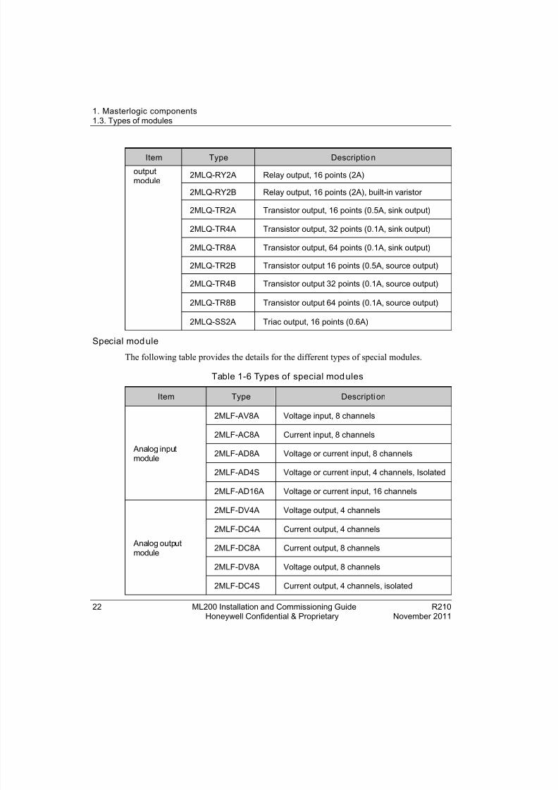
Item Type Descriptio n
outputmodule
2MLQ-RY2A Relay output, 16 points (2A)
2MLQ-RY2B Relay output, 16 points (2A), built-in varistor
2MLQ-TR2A Transistor output, 16 points (0.5A, sink output)
2MLQ-TR4A Transistor output, 32 points (0.1A, sink output)
2MLQ-TR8A Transistor output, 64 points (0.1A, sink output)
2MLQ-TR2B Transistor output 16 points (0.5A, source output)
2MLQ-TR4B Transistor output 32 points (0.1A, source output)
2MLQ-TR8B Transistor output 64 points (0.1A, source output)
2MLQ-SS2A Triac output, 16 points (0.6A)
Special mod ule
The following table provides the details for the different types of special modules.
Table 1-6 Types of special mod ules
Item Type Descripti on
Analog inputmodule
2MLF-AV8A Voltage input, 8 channels
2MLF-AC8A Current input, 8 channels
2MLF-AD8A Voltage or current input, 8 channels
2MLF-AD4S Voltage or current input, 4 channels, Isolated
2MLF-AD16A Voltage or current input, 16 channels
Analog output
module
2MLF-DV4A Voltage output, 4 channels
2MLF-DC4A Current output, 4 channels
2MLF-DC8A Current output, 8 channels
2MLF-DV8A Voltage output, 8 channels
2MLF-DC4S Current output, 4 channels, isolated

8/19/2019 Ml200 Installation and Commissioning Guide
http://slidepdf.com/reader/full/ml200-installation-and-commissioning-guide 23/92
1. Masterlogic components1.4. Types of base
R210 ML200 Installation and Commissioning Guide 23November 2011 Honeywell Confidential & Proprietary
High speed countermodule
2MLF-HO2A Pulse input, 2 channels, open collector
2MLF-HD2A Pulse input, 2 channels, line drive
Temperature inputmodule
2MLF-RD4A RTD input, 4channels
2MLF-RD4S RTD input, 4channels, Isolated
2MLF-TC4S Thermocouple input, 4channels, Isolated
Event input module 2MLF-SOEA Event input SOE, 32 channels
Communication moduleThe following table provides the details for the different types of communicationmodules.
Table 1-7 Types of co mmun ication mo dules
Item Type Descripti on
Snet
2MLL-C22A Serial communication, RS-232C 2channels
2MLL-C42A Serial communication, RS-422 2channels
2MLL-CH2A Serial communication, RS-232C/RS-422 (1ch each)
Dnet 2MLL-DMEA DeviceNet interface module
FEnet2MLL-EFMT Fast Ethernet, 100/100Mbps, RJ-45 (Electric)
2MLL-EFMF Fast Ethernet, 100/100Mbps, SC Type (Fiber Optic)
Pnet
2MLL-PMEA Profibus, master, 12Mbps, DP Standard
2MLL-PSEA Profibus slave interface
2MLL-PSRA Profibus remote interface, DP standard
ATTENTION
The 2MLL-PSRA must be installed only on ML200-IEC CPU bases.

8/19/2019 Ml200 Installation and Commissioning Guide
http://slidepdf.com/reader/full/ml200-installation-and-commissioning-guide 24/92
1. Masterlogic components1.4. Types of base
24 ML200 Installation and Commissioning Guide R210Honeywell Confidential & Proprietary November 2011
1.4 Types of baseThe ML200-IEC and ML200R comprises of main base and expansion base.
ML200-IEC Main base
The Main base of ML200-IEC consists of the power module, CPU module, I/O module,special module, and the communication module.
The following table provides the types of bases for ML200-IEC.
Table 1-8 Types of bases for ML 200-IEC
PLC types Part numb er Descriptio n
ML200-IEC
2MLB-M04A Main base 4 slot
2MLB-M06A Main base 6 slot
2MLB-M08A Main base 8 slot
2MLB-M12A Main base 12 slot
The following image illustrates the main base of ML200-IEC.
Figur e 1-1 Main base of ML200-IEC
The following table illustrates the details of the main base.

8/19/2019 Ml200 Installation and Commissioning Guide
http://slidepdf.com/reader/full/ml200-installation-and-commissioning-guide 25/92
1. Masterlogic components1.4. Types of base
R210 ML200 Installation and Commissioning Guide 25November 2011 Honeywell Confidential & Proprietary
Index Part Functio n
1 Base attached guide hole For attaching the main base to the panel in thecontrol panel.
2 Power module connector For installation of Power supply module.
3 Module built-in connector For installation of I/O, special and othercommunication modules.
4 FG terminal The ground terminal connected to the shieldedpattern of PCB board.
5 Expansion cableconnector
Connects the main base (CPU base) with theexpansion base.
6 CPU module connector For installation of CPU module
ML200-IEC Expansion b ase
The expansion base consists of the power module, I/O module, special module, andcommunication module.
The following table provides the types of expansion bases for ML200-IEC.
Table 1-9 Types of expansion bases f or ML200-IEC
PLC types Part numb er Descripti on
ML200-IEC
2MLB-E04A Expansion base 4 slot
2MLB-E06A Expansion base 6 slot
2MLB-E08A Expansion base 8 slot
2MLB-E12A Expansion base 12 slot
The following image illustrates the expansion base of ML200-IEC.
8/19/2019 Ml200 Installation and Commissioning Guide
http://slidepdf.com/reader/full/ml200-installation-and-commissioning-guide 26/92
1. Masterlogic components1.4. Types of base
26 ML200 Installation and Commissioning Guide R210Honeywell Confidential & Proprietary November 2011
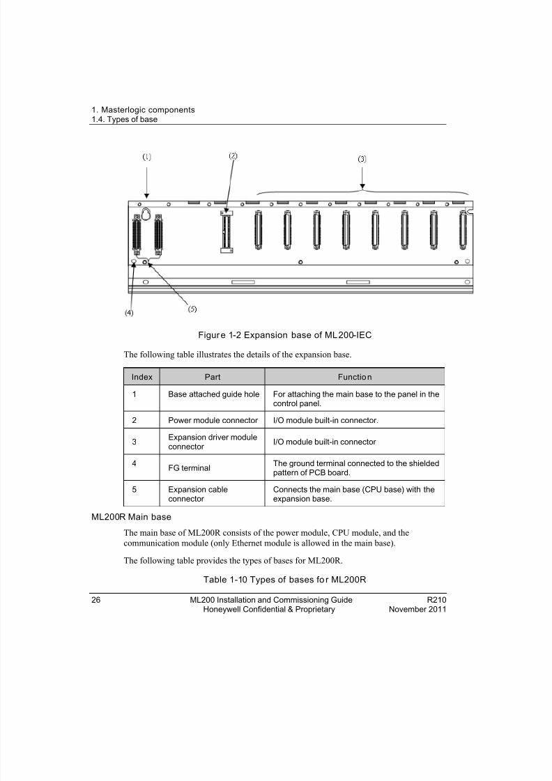
Figur e 1-2 Expansion base of ML200-IEC
The following table illustrates the details of the expansion base.
Index Part Functio n
1 Base attached guide hole For attaching the main base to the panel in thecontrol panel.
2 Power module connector I/O module built-in connector.
3 Expansion driver moduleconnector I/O module built-in connector
4 FG terminal The ground terminal connected to the shieldedpattern of PCB board.
5 Expansion cableconnector
Connects the main base (CPU base) with theexpansion base.
ML200R Main base
The main base of ML200R consists of the power module, CPU module, and the
communication module (only Ethernet module is allowed in the main base).The following table provides the types of bases for ML200R.
Table 1-10 Types of bases fo r ML200R

8/19/2019 Ml200 Installation and Commissioning Guide
http://slidepdf.com/reader/full/ml200-installation-and-commissioning-guide 27/92

8/19/2019 Ml200 Installation and Commissioning Guide
http://slidepdf.com/reader/full/ml200-installation-and-commissioning-guide 28/92
1. Masterlogic components1.4. Types of base
28 ML200 Installation and Commissioning Guide R210Honeywell Confidential & Proprietary November 2011
Figur e 1-4 Main base of 2MLR-M06P
The following table illustrates the main base details of 2MLR-M02P and 2MLR-M06P.
Index Part Functio n
1 Base attached guide hole For attaching the main base to the panel in thecontrol panel.
2 Power module connector For installation of Power supply module.
3 CPU module connector For installation of CPU module (2 slots).
4 Module built-in connector For installation of communication modules.
5 FG terminal The ground terminal connected to the shieldedpattern of PCB board.
ML200R Expansion base
ML200R input/output base communication includes expansion base and expansion drivermodules. The following are the two types of IO link topology for ML200R.
• Expansion base without dual IO link redundancy
• Expansion base with dual IO link redundancy

8/19/2019 Ml200 Installation and Commissioning Guide
http://slidepdf.com/reader/full/ml200-installation-and-commissioning-guide 29/92
1. Masterlogic components1.4. Types of base
R210 ML200 Installation and Commissioning Guide 29November 2011 Honeywell Confidential & Proprietary
Expansion base with out dual IO link redund ancy
The expansion base of ML200R consists of the power module, expansion driver module,I/O module, special module, and the communication module. (Ethernet module is notallowed in the expansion base).
The following table provides the details about expansion base and expansion drivermodule for ML200R.
Table 1-11 Expansion base and expansion driv er modu le for ML200R
PLC types Part numb er Descripti on
ML200R
2MLR-E12P Expansion base 12 slot
2MLR-DBSF Expansion driver module FO
2MLR-DBST Expansion driver module TP
2MLR-DBSH Expansion driver module TP/FO
The following image illustrates the expansion base of ML200R, which does not supportdual I/O link redundancy.
Figure 1-5 Expansion base of ML200R (without dual I/O link redundancy)
8/19/2019 Ml200 Installation and Commissioning Guide
http://slidepdf.com/reader/full/ml200-installation-and-commissioning-guide 30/92
1. Masterlogic components1.4. Types of base
30 ML200 Installation and Commissioning Guide R210Honeywell Confidential & Proprietary November 2011
The following table illustrates the expansion base details of ML200R, without dual I/Olink redundancy.
Index Part Functio n
1 Base attached guide hole For attaching the main base to the panel in thecontrol panel.
2 Power module connector For installation of power supply module.
3 Expansion driver moduleconnector For installation of expansion driver module.
4 Module built-in connector For installation of I/O, special andcommunication modules other than Ethernetmodule.
5 FG terminal The ground terminal connected to the shieldedpattern of PCB board.
Expansion base with dual IO link redundancy
The expansion base of ML-200R consists of the power module, expansion driver module,I/O module, special module, and the communication module. (Ethernet module is notallowed in the expansion base).
The following table provides the details about expansion base and expansion driver
module for ML200R.
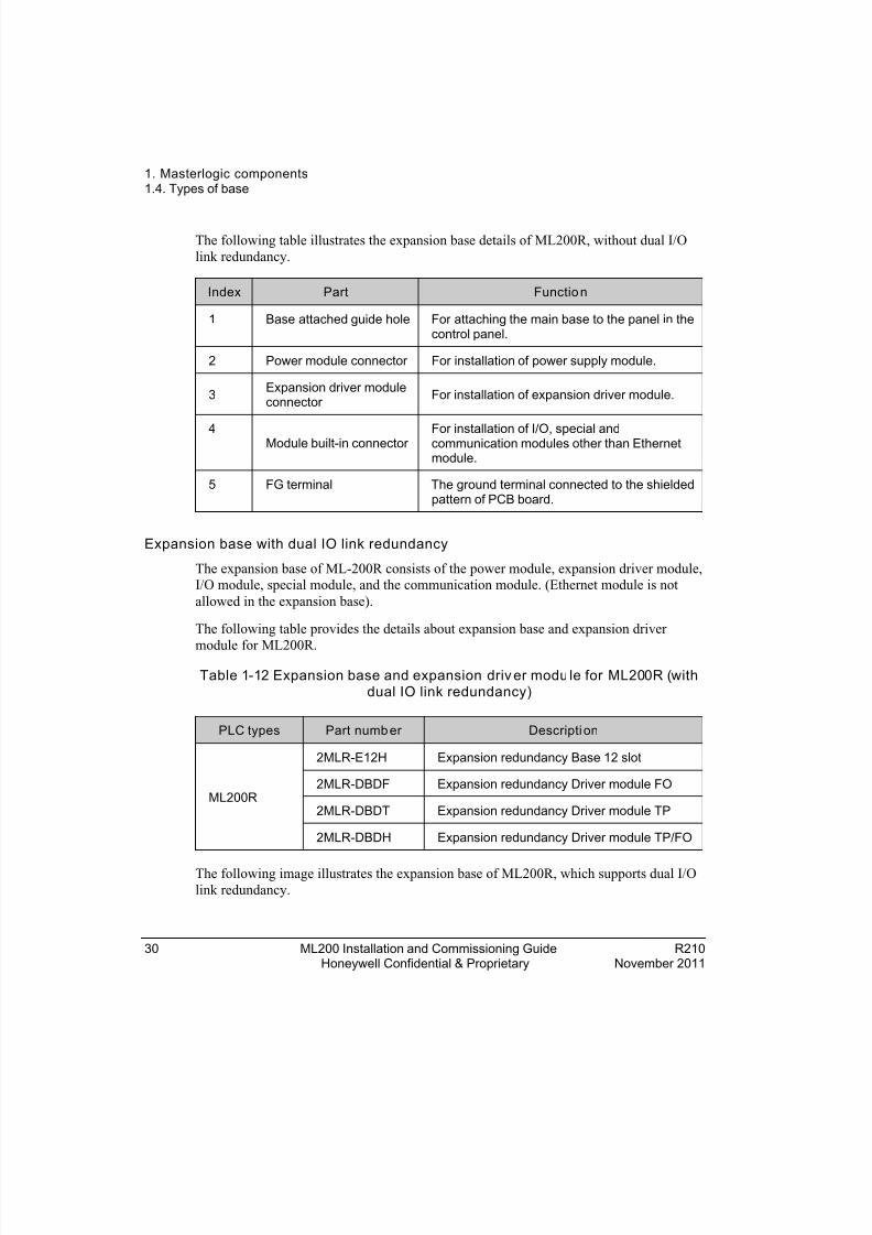
Table 1-12 Expansion base and expansion driv er modu le for ML200R (withdual IO link redundancy)
PLC types Part numb er Descripti on
ML200R
2MLR-E12H Expansion redundancy Base 12 slot
2MLR-DBDF Expansion redundancy Driver module FO
2MLR-DBDT Expansion redundancy Driver module TP
2MLR-DBDH Expansion redundancy Driver module TP/FO
The following image illustrates the expansion base of ML200R, which supports dual I/Olink redundancy.
8/19/2019 Ml200 Installation and Commissioning Guide
http://slidepdf.com/reader/full/ml200-installation-and-commissioning-guide 31/92
1. Masterlogic components1.5. Types of cables
R210 ML200 Installation and Commissioning Guide 31November 2011 Honeywell Confidential & Proprietary
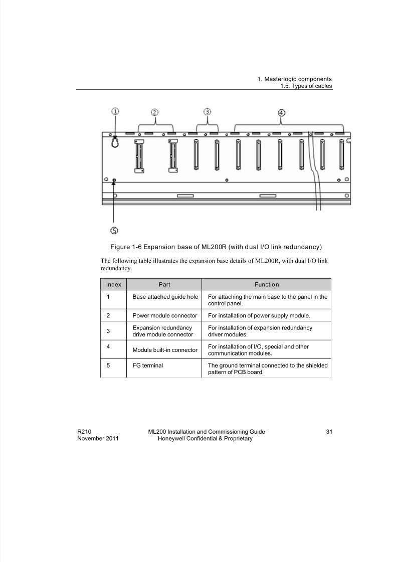
Figure 1-6 Expansion base of ML200R (with d ual I/O link redundancy)
The following table illustrates the expansion base details of ML200R, with dual I/O linkredundancy.
Index Part Functio n
1 Base attached guide hole For attaching the main base to the panel in thecontrol panel.
2 Power module connector For installation of power supply module.
3 Expansion redundancydrive module connector
For installation of expansion redundancydriver modules.
4 Module built-in connector For installation of I/O, special and othercommunication modules.
5 FG terminal The ground terminal connected to the shieldedpattern of PCB board.
8/19/2019 Ml200 Installation and Commissioning Guide
http://slidepdf.com/reader/full/ml200-installation-and-commissioning-guide 32/92
1. Masterlogic components1.5. Types of cables
32 ML200 Installation and Commissioning Guide R210Honeywell Confidential & Proprietary November 2011
1.5 Types of cablesCables fo r ML 200-IEC
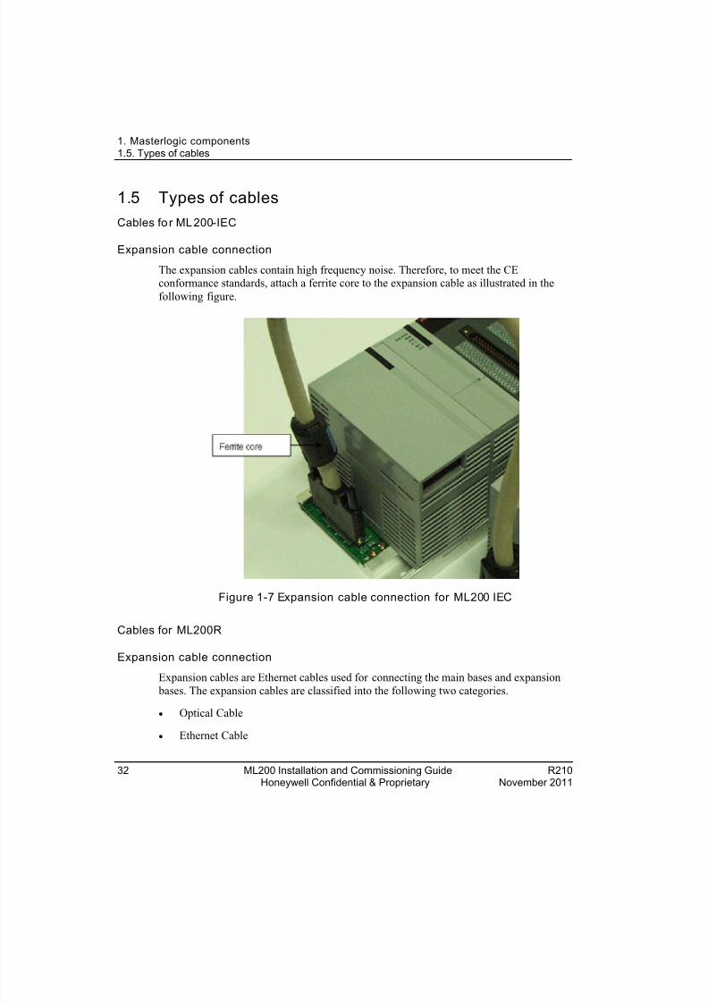
Expansion cable connection
The expansion cables contain high frequency noise. Therefore, to meet the CEconformance standards, attach a ferrite core to the expansion cable as illustrated in thefollowing figure.
Figure 1-7 Expansion cable connection for ML200 IEC
Cables for ML200R
Expansion cable connection
Expansion cables are Ethernet cables used for connecting the main bases and expansion bases. The expansion cables are classified into the following two categories.
• Optical Cable
• Ethernet Cable
8/19/2019 Ml200 Installation and Commissioning Guide
http://slidepdf.com/reader/full/ml200-installation-and-commissioning-guide 33/92
1. Masterlogic components1.5. Types of cables
R210 ML200 Installation and Commissioning Guide 33November 2011 Honeywell Confidential & Proprietary
The electrical and optical cables are provided for use in accordance with the networktype.
Optical cables
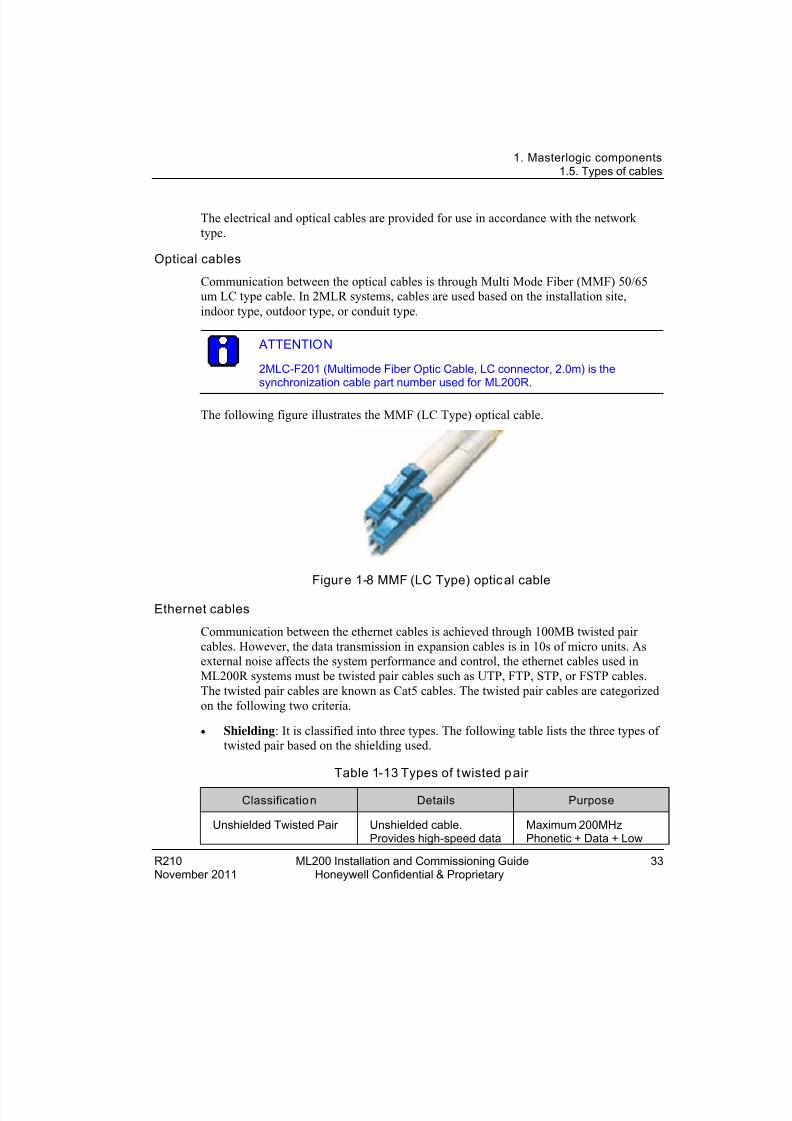
Communication between the optical cables is through Multi Mode Fiber (MMF) 50/65um LC type cable. In 2MLR systems, cables are used based on the installation site,indoor type, outdoor type, or conduit type.
ATTENTION
2MLC-F201 (Multimode Fiber Optic Cable, LC connector, 2.0m) is thesynchronization cable part number used for ML200R.
The following figure illustrates the MMF (LC Type) optical cable.
Figur e 1-8 MMF (LC Type) optic al cable
Ethernet cables
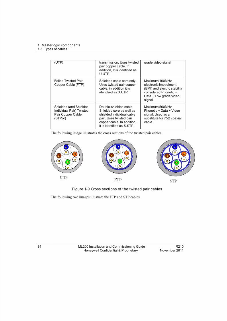
Communication between the ethernet cables is achieved through 100MB twisted paircables. However, the data transmission in expansion cables is in 10s of micro units. Asexternal noise affects the system performance and control, the ethernet cables used inML200R systems must be twisted pair cables such as UTP, FTP, STP, or FSTP cables.The twisted pair cables are known as Cat5 cables. The twisted pair cables are categorizedon the following two criteria.
• Shielding : It is classified into three types. The following table lists the three types oftwisted pair based on the shielding used.
Table 1-13 Types of t wisted p air
Classificatio n Details Purpose
Unshielded Twisted Pair Unshielded cable.Provides high-speed data
Maximum 200MHzPhonetic + Data + Low
8/19/2019 Ml200 Installation and Commissioning Guide
http://slidepdf.com/reader/full/ml200-installation-and-commissioning-guide 34/92
1. Masterlogic components1.5. Types of cables
34 ML200 Installation and Commissioning Guide R210Honeywell Confidential & Proprietary November 2011
(UTP) transmission. Uses twistedpair copper cable. Inaddition, It is identified asU.UTP.
grade video signal
Foiled Twisted PairCopper Cable (FTP)
Shielded cable core only.Uses twisted pair coppercable. in addition it isidentified as S.UTP
Maximum 100MHzelectronic impediment(EMI) and electric stabilityconsidered Phonetic +Data + Low grade videosignal
Shielded (and ShieldedIndividual Pair) TwistedPair Copper Cable(STPor)
Double-shielded cable.Shielded core as well asshielded individual cablepair. Uses twisted paircopper cable. In addition,it is identified as S.STP.
Maximum 500MHzPhonetic + Data + Videosignal. Used as asubstitute for 75Ω coaxialcable
The following image illustrates the cross sections of the twisted pair cables.
Figure 1-9 Cross secti ons of t he twisted pair cables
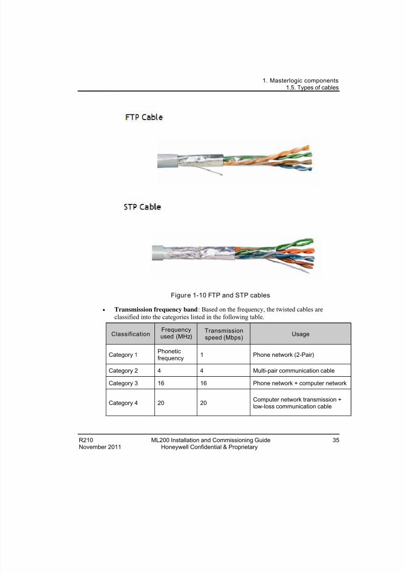
The following two images illustrate the FTP and STP cables.
8/19/2019 Ml200 Installation and Commissioning Guide
http://slidepdf.com/reader/full/ml200-installation-and-commissioning-guide 35/92
1. Masterlogic components1.5. Types of cables
R210 ML200 Installation and Commissioning Guide 35November 2011 Honeywell Confidential & Proprietary
Figure 1-10 FTP and STP cables
• Transmission frequency band : Based on the frequency, the twisted cables areclassified into the categories listed in the following table.
ClassificationFrequencyused (MHz)
Transmissionspeed (Mbps) Usage
Category 1 Phoneticfrequency 1 Phone network (2-Pair)
Category 2 4 4 Multi-pair communication cable
Category 3 16 16 Phone network + computer network
Category 4 20 20 Computer network transmission +low-loss communication cable

8/19/2019 Ml200 Installation and Commissioning Guide
http://slidepdf.com/reader/full/ml200-installation-and-commissioning-guide 36/92
1. Masterlogic components1.5. Types of cables
36 ML200 Installation and Commissioning Guide R210Honeywell Confidential & Proprietary November 2011
ClassificationFrequencyused (MHz)
Transmissionspeed (Mbps) Usage
Category 5 andEnhancedCategory 5
100 100 Digital phone network + computernetwork low-loss, broadband cable
8/19/2019 Ml200 Installation and Commissioning Guide
http://slidepdf.com/reader/full/ml200-installation-and-commissioning-guide 37/92
R210 ML200 Installation and Commissioning Guide 37November 2011 Honeywell Confidential & Proprietary
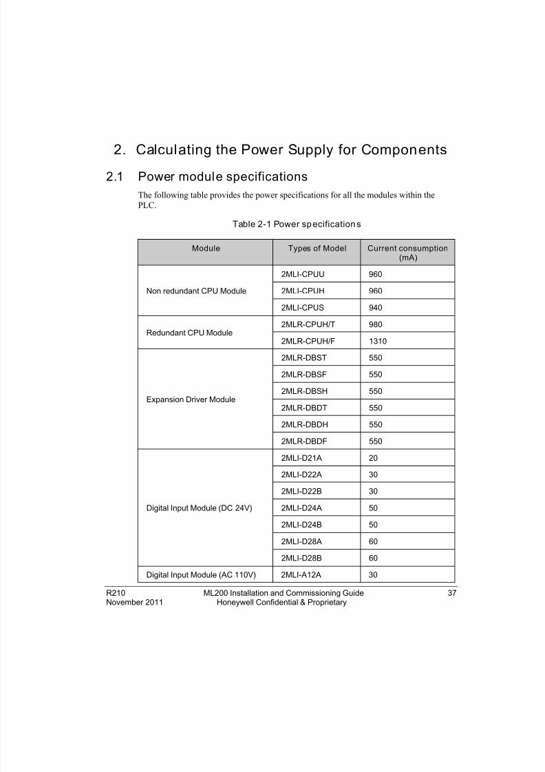
2. Calculating the Power Supply for Components
2.1 Power module specificationsThe following table provides the power specifications for all the modules within thePLC.
Table 2-1 Power sp ecification s
Module Types of Model Current consumption(mA)
Non redundant CPU Module
2MLI-CPUU 960
2MLI-CPUH 960
2MLI-CPUS 940
Redundant CPU Module2MLR-CPUH/T 980
2MLR-CPUH/F 1310
Expansion Driver Module
2MLR-DBST 550
2MLR-DBSF 550
2MLR-DBSH 550
2MLR-DBDT 550
2MLR-DBDH 550
2MLR-DBDF 550
Digital Input Module (DC 24V)
2MLI-D21A 20
2MLI-D22A 30
2MLI-D22B 30
2MLI-D24A 50
2MLI-D24B 50
2MLI-D28A 60
2MLI-D28B 60
Digital Input Module (AC 110V) 2MLI-A12A 30

8/19/2019 Ml200 Installation and Commissioning Guide
http://slidepdf.com/reader/full/ml200-installation-and-commissioning-guide 38/92
2. Calculating the Power Supply for Components2.1. Power module specifications
38 ML200 Installation and Commissioning Guide R210Honeywell Confidential & Proprietary November 2011
Module Types of Model Current consumption(mA)
Digital Input Module (AC220V) 2MLI-A21A 20
Relay output module
2MLQ-RY1A 250
2MLQ-RY2A 500
2MLQ-RY2B 500
Digital Output Module (Transistor)
2MLQ-TR2A 70
2MLQ-TR2B 70
2MLQ-TR4A 130
2MLQ-TR4B 130
2MLQ-TR8A 230
2MLQ-TR8B 230
Digital Output Module (Triac)2MLQSS2A 300
2MLFDV4S 200
Analog Input Module
2MLF-AV8A 420
2MLF-AC8A 420
2MLF-AD8A 420
2MLF-AD16A 330
2MLF-AD4S 610
Analog Output Module
2MLF-DV4A 190
2MLF-DC4A 190
2MLF-DV8A 147
2MLF-DC8A 243
2MLF-DC4S 200
2MLF-DV4S 200
Temperature Input Module 2MLF-TC4S 610

8/19/2019 Ml200 Installation and Commissioning Guide
http://slidepdf.com/reader/full/ml200-installation-and-commissioning-guide 39/92
2. Calculating the Power Supply for Components2.2. Selecting the Power supply
R210 ML200 Installation and Commissioning Guide 39November 2011 Honeywell Confidential & Proprietary
Module Types of Model Current consumption(mA)
2MLF-RD4A 490
High-Speed Counter Module2MLF-HO2A 270
2MLF-HD2A 330
FEnet Module2MLL-EFMF 650
2MLL-EFMT 420
Snet Module
2MLL-C22A 330
2MLL-C42A 300
2MLL-CH2A 340
Profibus-DP Module 2MLL-PMEA 560
Profibus Remote Interface 2MLL-PSRA 550
Profibus Remote Slave Interface 2MLL-PSEA 550
2.2 Selecting the Power supplyThe selection of a power module is determined by the current and voltage needed by the
system. The voltage requirement of a system is calculated as the sum of the currentconsumption by the digital I/O modules, special modules, CPU module, power moduleand the communication module (installed on the same base as the power module.)
The system does not operate normally, if the rated output capacity of the power moduleexceeds the predefined limit.
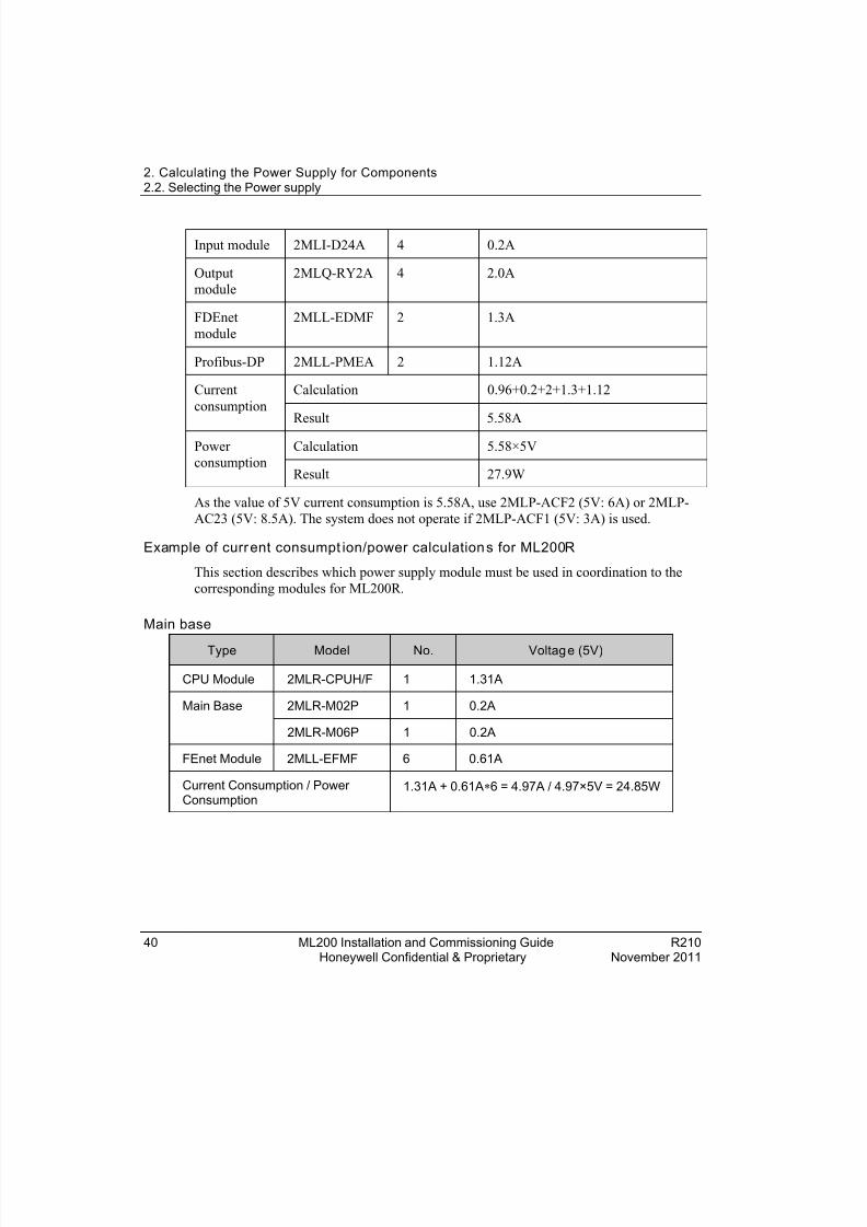
Example of cur rent consu mptio n/power calculations for ML200-IEC
The following table describes which power supply module must be used in coordinationto the corresponding modules for ML200-IEC.
Type Model Quantity Voltage (5V)
CPU module 2MLI-CPUU 1 0.96A
12 Slot basic base
2MLB-M12A - -
8/19/2019 Ml200 Installation and Commissioning Guide
http://slidepdf.com/reader/full/ml200-installation-and-commissioning-guide 40/92
2. Calculating the Power Supply for Components2.2. Selecting the Power supply
40 ML200 Installation and Commissioning Guide R210Honeywell Confidential & Proprietary November 2011
Input module 2MLI-D24A 4 0.2A
Outputmodule
2MLQ-RY2A 4 2.0A
FDEnetmodule
2MLL-EDMF 2 1.3A
Profibus-DP 2MLL-PMEA 2 1.12A
Currentconsumption
Calculation 0.96+0.2+2+1.3+1.12
Result 5.58A
Powerconsumption
Calculation 5.58×5V
Result 27.9W
As the value of 5V current consumption is 5.58A, use 2MLP-ACF2 (5V: 6A) or 2MLP-AC23 (5V: 8.5A). The system does not operate if 2MLP-ACF1 (5V: 3A) is used.
Example of curr ent consumpt ion/power calculation s for ML200R
This section describes which power supply module must be used in coordination to thecorresponding modules for ML200R.
Main base
Type Model No. Voltag e (5V)
CPU Module 2MLR-CPUH/F 1 1.31A
Main Base 2MLR-M02P 1 0.2A
2MLR-M06P 1 0.2A
FEnet Module 2MLL-EFMF 6 0.61A
Current Consumption / PowerConsumption
1.31A + 0.61A ∗6 = 4.97A / 4.97×5V = 24.85W

8/19/2019 Ml200 Installation and Commissioning Guide
http://slidepdf.com/reader/full/ml200-installation-and-commissioning-guide 41/92
2. Calculating the Power Supply for Components2.2. Selecting the Power supply
R210 ML200 Installation and Commissioning Guide 41November 2011 Honeywell Confidential & Proprietary
Expansion base
Type Model No. Voltag e (5V)
ExpansionDriver
2MLR-DBSF 1 0.65A
ExpansionBase
2MLR-E12P 1 0.21 A
DI Module 2MLI-D24A 2 0.05A
DO Module 2MLQ-RY2A 6 0.5A
AI Module 2MLF-AD4S 2 0.61A
Profibus-DP 2MLL-PMEA 2 0.56A
Current Consumption / PowerConsumption
0.65A + 0.05A ∗2 + 0.5A ∗6 + 0.61A ∗2 +0.56A∗2 = 6.09ª / 6.09A × 5V = 30.85 W
Sum of current consumption is 6.17A. Hence, use 2MLR-AC13 or 2MLR-AC23.
ATTENTION
Maximum power consumption of PLC can be derived from the efficiency ofpower module.
Example: Sum of 5V consumption x Minimum efficiency of Power module =100W/0.65 = 154W.
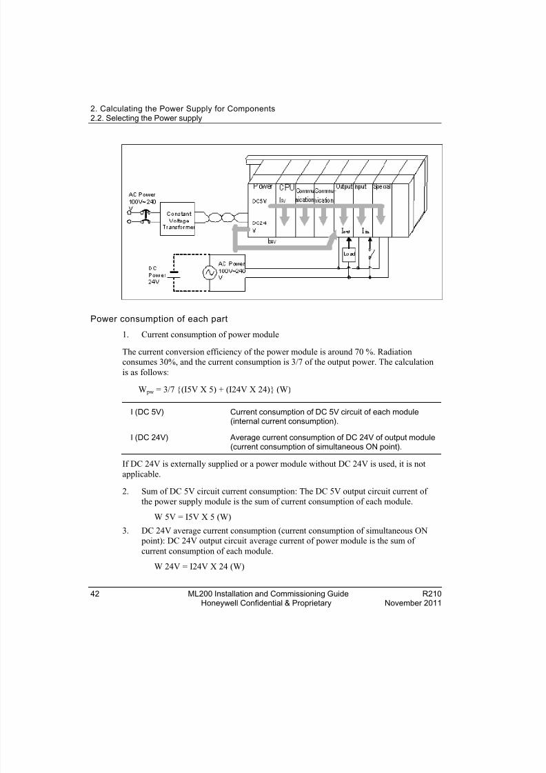
The following figure illustrates the method used for calculating the current consumptionof the PLC system necessary for heat protection design.
8/19/2019 Ml200 Installation and Commissioning Guide
http://slidepdf.com/reader/full/ml200-installation-and-commissioning-guide 42/92
2. Calculating the Power Supply for Components2.2. Selecting the Power supply
42 ML200 Installation and Commissioning Guide R210Honeywell Confidential & Proprietary November 2011
Power consumption of each part
1. Current consumption of power module
The current conversion efficiency of the power module is around 70 %. Radiationconsumes 30%, and the current consumption is 3/7 of the output power. The calculationis as follows:
W pw = 3/7 (I5V X 5) + (I24V X 24) (W)
I (DC 5V) Current consumption of DC 5V circuit of each module(internal current consumption).
I (DC 24V) Average current consumption of DC 24V of output module(current consumption of simultaneous ON point).
If DC 24V is externally supplied or a power module without DC 24V is used, it is notapplicable.
2. Sum of DC 5V circuit current consumption: The DC 5V output circuit current ofthe power supply module is the sum of current consumption of each module.
W 5V = I5V X 5 (W)
3. DC 24V average current consumption (current consumption of simultaneous ON
point): DC 24V output circuit average current of power module is the sum ofcurrent consumption of each module.
W 24V = I24V X 24 (W)

8/19/2019 Ml200 Installation and Commissioning Guide
http://slidepdf.com/reader/full/ml200-installation-and-commissioning-guide 43/92
2. Calculating the Power Supply for Components2.2. Selecting the Power supply
R210 ML200 Installation and Commissioning Guide 43November 2011 Honeywell Confidential & Proprietary
4. Average current consumption by output voltage drop of output module (currentconsumption of simultaneous ON point).
i. W out = I out X V drop X Output point X Simultaneous ON rate (W)ii. Iout: Output current (current in actual use) (A)
iii. Vdrop : Voltage drop of each output module (V)
5. Input average current consumption of input module (current consumption ofsimultaneous ON point).
i. W in = I in X E X Input point X Simultaneous ON rate (W)ii. Iin: Input current (actual value in case of AC) (A)
iii. E: Input voltage (voltage in actual use) (V)
6. Current consumption of Special module power assembly
WS = I5V X 5 + I24V X 24 + I100V X 100 (W)
The sum of the current consumption calculated for each block is the total currentconsumption of PLC system.
W = WPW + W5V + W24V + W out + W in + W s (W)
Calculate the amount of radiation according to this total current consumption (W) andreview the temperature rising in the control panel. Use the following formula for thecalculation of the temperature rise in the control panel.
T = W / UA [ °C]
Where,
W = power consumption of the entire PLC system (the calculated value)
A = surface area of control panel [m 2]
U: If equalizing the temperature of the control panel by using a fan and others

8/19/2019 Ml200 Installation and Commissioning Guide
http://slidepdf.com/reader/full/ml200-installation-and-commissioning-guide 44/92
2. Calculating the Power Supply for Components2.2. Selecting the Power supply
44 ML200 Installation and Commissioning Guide R210Honeywell Confidential & Proprietary November 2011
8/19/2019 Ml200 Installation and Commissioning Guide
http://slidepdf.com/reader/full/ml200-installation-and-commissioning-guide 45/92
R210 ML200 Installation and Commissioning Guide 45November 2011 Honeywell Confidential & Proprietary
3. Plan and Install MLPLC
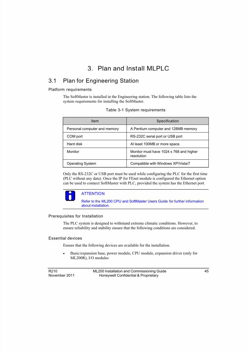
3.1 Plan for Engineering StationPlatform requirements
The SoftMaster is installed in the Engineering station. The following table lists thesystem requirements for installing the SoftMaster.
Table 3-1 System requirements
Item Specification
Personal computer and memory A Pentium computer and 128MB memory
COM port RS-232C serial port or USB port
Hard disk At least 100MB or more space.
Monitor Monitor must have 1024 x 768 and higherresolution
Operating System Compatible with Windows XP/Vista/7
Only the RS-232C or USB port must be used while configuring the PLC for the first time(PLC without any data). Once the IP for FEnet module is configured the Ethernet optioncan be used to connect SoftMaster with PLC, provided the system has the Ethernet port.
ATTENTION
Refer to the ML200 CPU and SoftMaster Users Guide for further informationabout installation.
Prerequisites for Installation
The PLC system is designed to withstand extreme climatic conditions. However, toensure reliability and stability ensure that the following conditions are considered.
Essential devices
Ensure that the following devices are available for the installation.
• Basic/expansion base, power module, CPU module, expansion driver (only forML200R), I/O modules

8/19/2019 Ml200 Installation and Commissioning Guide
http://slidepdf.com/reader/full/ml200-installation-and-commissioning-guide 46/92
3. Plan and Install MLPLC3.1. Plan for Engineering Station
46 ML200 Installation and Commissioning Guide R210Honeywell Confidential & Proprietary November 2011
• Synchronization cable (only for ML200R) and expansion cable
• USB programming cable
• SoftMaster (PLC Configuration and Programming Software)
Environmental condit ions
Dos
• Install the PLC in a control panel, which is waterproof and can withstand vibration.
• Ensure an ambient temperature of 0 ~ 55C.
• Ensure incremental Humidity: 5 ~ 95 %.
Don’ts
• Do not expose the PLC to direct sun-light.
• Do not expose the PLC to sudden changes in the temperature.
• Do not expose the PLC to corrosive or inflammable gases.
Installation conditions
• While drilling holes, fixing screws or wiring, ensure that no wire or any othermetallic part enters the PLC.
• Do not install the PLC on a panel that has a high-voltage device.
• Maintain a distance of at least 50mm from the wiring duct or surrounding modules.
• Ensure the grounding at a place where surrounding noise is minimal.
Heat protection design of control panel
• In case the PLC is installed in an airtight control panel, the heat protection designmust be ensured, considering the radiation of other equipment, and heat from thePLC. When air circulation is provided using a vent or a general fan, the flow of dust
particles or gas can hamper the functioning of the PLC system.
• Installing a filter or use of an airtight heat exchanger is recommended.

8/19/2019 Ml200 Installation and Commissioning Guide
http://slidepdf.com/reader/full/ml200-installation-and-commissioning-guide 47/92
3. Plan and Install MLPLC3.1. Plan for Engineering Station
R210 ML200 Installation and Commissioning Guide 47November 2011 Honeywell Confidential & Proprietary
Precaution s for ins talling th e base
The following precautions must be taken while installing a PLC on the control panel.Ensure sufficient ventilation for the modules, especially the upper part of the modules. Inaddition, this helps in changing the modules, if required.
1. A, B: More than 5cm
2. C, D: More than 5cm for easy installation of module.
− More than 15cm is recommended if fiber optic modules or full loaded powersupply is used.
3. E :More than 8cm, if fiber optic cable or connector-type I/O modules are used ormore than 10cm, if FTP cable is used.
4. If the PLC is installed near a Contactor/Breaker, it is recommended to use aContactor/Breaker (Large Size) in a different panel.
5. If necessary, install wiring duct for routing the cables. Consider the following points while installing a wiring duct:
− When installing the wiring duct on the upper part of the PLC, ensure that itsdistance is more than 50mm to enable adequate ventilation. Maintain sufficientdistance from the upper part of the PLC, so that the module can be removedeasily.
− When installing the wiring duct on the lower part of the PLC, take into accountthe connection of the optical cable or coaxial cable, and the minimum cableradius.
6. Install PLC in the direction as shown in the following figure. This helps in protecting the PLC from radiation.
8/19/2019 Ml200 Installation and Commissioning Guide
http://slidepdf.com/reader/full/ml200-installation-and-commissioning-guide 48/92
3. Plan and Install MLPLC3.1. Plan for Engineering Station
48 ML200 Installation and Commissioning Guide R210Honeywell Confidential & Proprietary November 2011
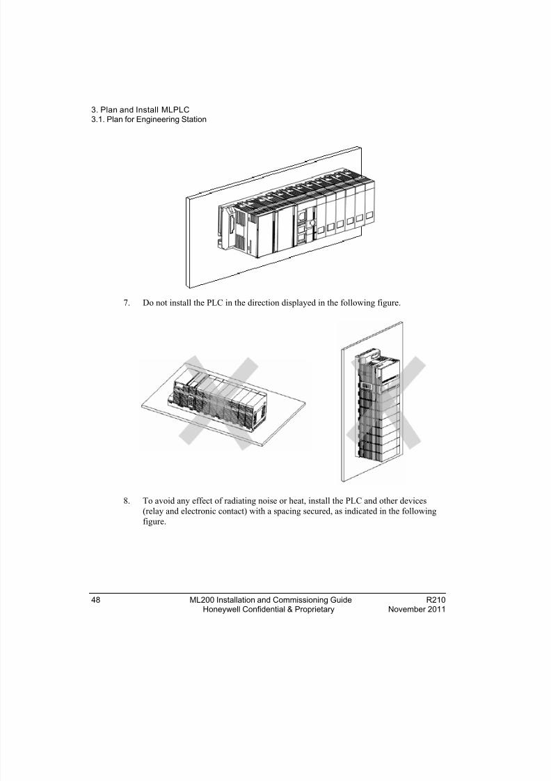
7. Do not install the PLC in the direction displayed in the following figure.
8. To avoid any effect of radiating noise or heat, install the PLC and other devices(relay and electronic contact) with a spacing secured, as indicated in the followingfigure.
8/19/2019 Ml200 Installation and Commissioning Guide
http://slidepdf.com/reader/full/ml200-installation-and-commissioning-guide 49/92
3. Plan and Install MLPLC3.1. Plan for Engineering Station
R210 ML200 Installation and Commissioning Guide 49November 2011 Honeywell Confidential & Proprietary
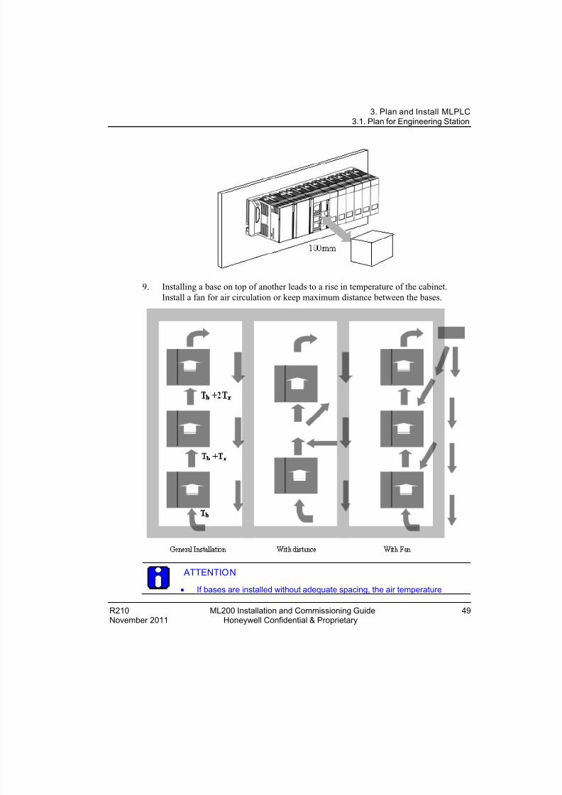
9. Installing a base on top of another leads to a rise in temperature of the cabinet.Install a fan for air circulation or keep maximum distance between the bases.
ATTENTION
• If bases are installed without adequate spacing, the air temperature

8/19/2019 Ml200 Installation and Commissioning Guide
http://slidepdf.com/reader/full/ml200-installation-and-commissioning-guide 50/92
3. Plan and Install MLPLC3.1. Plan for Engineering Station
50 ML200 Installation and Commissioning Guide R210Honeywell Confidential & Proprietary November 2011
(Tb + Tr) may rise up to 15°C for the fiber optic module and the moduleinstalled right above the power module.
• Ensure that air temperature around the module does not exceed 55°C.
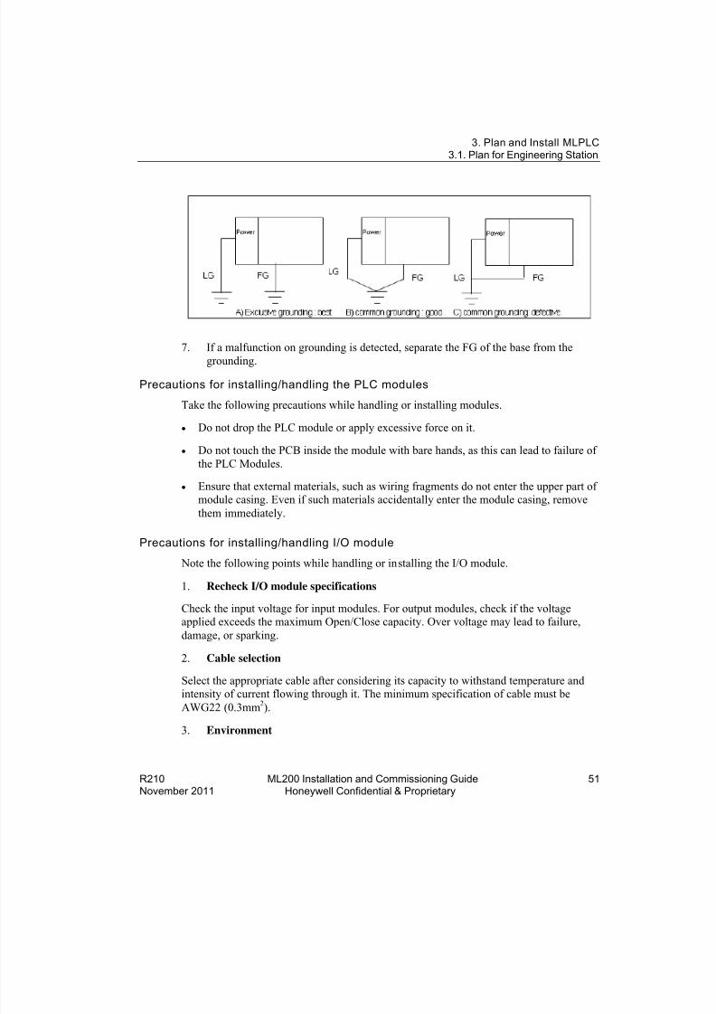
Grounding requirements
Grounding for cabinet mount ing
1. Sufficient measures against noise are taken in the PLC, making it possible to beused without grounding.
2. Use dedicated grounding for the wires as far as possible.
3. If the grounding is functional, use class 3 grounding, (grounding resistance must be100 Ω or less).
4. If it is not possible to use dedicated grounding, use common grounding, as depictedin the following figure.
5. Use more than 2mm 2 cables for grounding. Place the earth point near the PLC asmuch as possible to limit the length of grounding cable.
6. Separate Line Ground (LG) of power module and Frame Ground (FG) of base board for grounding.
8/19/2019 Ml200 Installation and Commissioning Guide
http://slidepdf.com/reader/full/ml200-installation-and-commissioning-guide 51/92
3. Plan and Install MLPLC3.1. Plan for Engineering Station
R210 ML200 Installation and Commissioning Guide 51November 2011 Honeywell Confidential & Proprietary
7. If a malfunction on grounding is detected, separate the FG of the base from thegrounding.
Precautions for installing/handling the PLC modules
Take the following precautions while handling or installing modules.
• Do not drop the PLC module or apply excessive force on it.
• Do not touch the PCB inside the module with bare hands, as this can lead to failure ofthe PLC Modules.
• Ensure that external materials, such as wiring fragments do not enter the upper part ofmodule casing. Even if such materials accidentally enter the module casing, removethem immediately.
Precautions for installing/handling I/O module
Note the following points while handling or installing the I/O module.
1. Recheck I/O module specifications
Check the input voltage for input modules. For output modules, check if the voltageapplied exceeds the maximum Open/Close capacity. Over voltage may lead to failure,damage, or sparking.
2. Cable selection
Select the appropriate cable after considering its capacity to withstand temperature andintensity of current flowing through it. The minimum specification of cable must be
AWG22 (0.3mm2
). 3. Environment
8/19/2019 Ml200 Installation and Commissioning Guide
http://slidepdf.com/reader/full/ml200-installation-and-commissioning-guide 52/92
3. Plan and Install MLPLC3.2. Mounting Chassis
52 ML200 Installation and Commissioning Guide R210Honeywell Confidential & Proprietary November 2011
When wiring an I/O module, ensure that it is not too close to a heat emitting equipment.In addition, avoid the wires from coming in direct contact with oil, as it may cause ashort circuit, breakage, or can cause abnormal errors during operation.
4. Polarity
The polarity of the module terminals and that of the field signal must be the same.
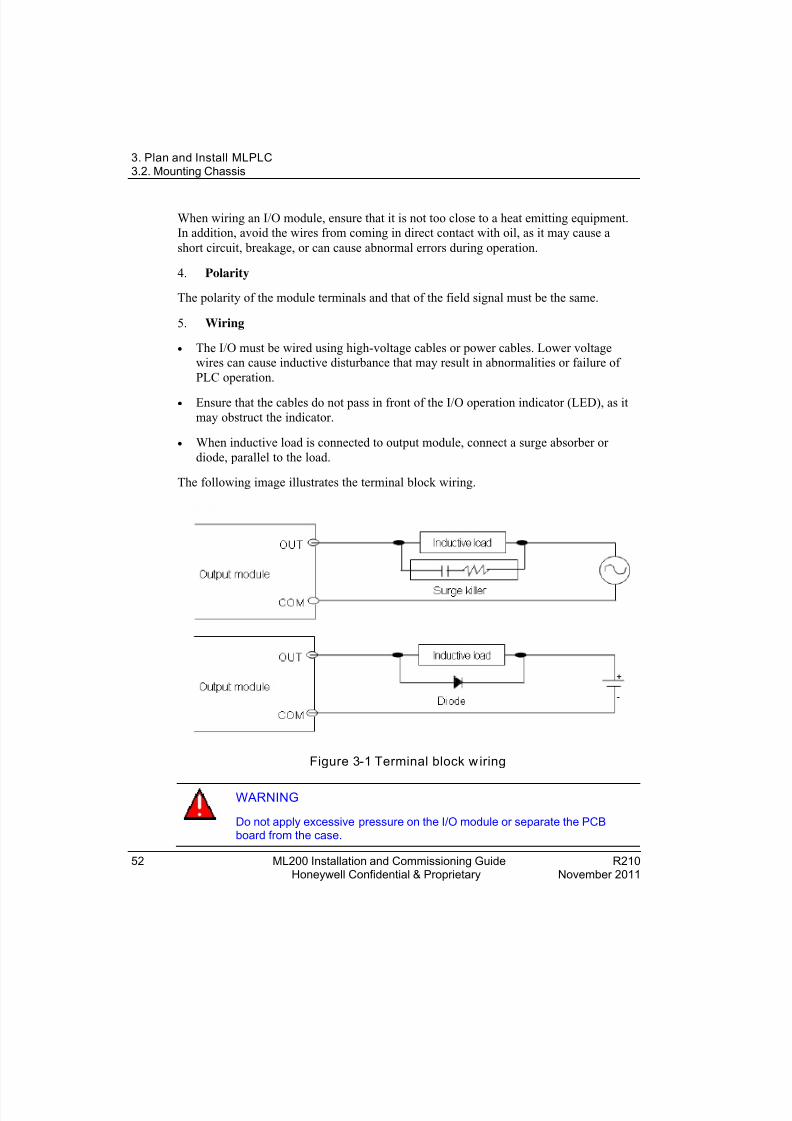
5. Wiring
• The I/O must be wired using high-voltage cables or power cables. Lower voltagewires can cause inductive disturbance that may result in abnormalities or failure ofPLC operation.
• Ensure that the cables do not pass in front of the I/O operation indicator (LED), as itmay obstruct the indicator.
• When inductive load is connected to output module, connect a surge absorber ordiode, parallel to the load.
The following image illustrates the terminal block wiring.
Figure 3-1 Terminal block w iring
WARNING
Do not apply excessive pressure on the I/O module or separate the PCBboard from the case.
8/19/2019 Ml200 Installation and Commissioning Guide
http://slidepdf.com/reader/full/ml200-installation-and-commissioning-guide 53/92
3. Plan and Install MLPLC3.2. Mounting Chassis
R210 ML200 Installation and Commissioning Guide 53November 2011 Honeywell Confidential & Proprietary
3.2 Mounting ChassisCabinet mounting
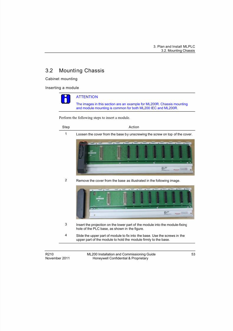
Inserting a module
ATTENTION
The images in this section are an example for ML200R. Chassis mountingand module mounting is common for both ML200 IEC and ML200R.
Perform the following steps to insert a module.
Step Action
1 Loosen the cover from the base by unscrewing the screw on top of the cover.
2 Remove the cover from the base as illustrated in the following image.
3 Insert the projection on the lower part of the module into the module-fixinghole of the PLC base, as shown in the figure.
4 Slide the upper part of module to fix into the base. Use the screws in theupper part of the module to hold the module firmly to the base.

8/19/2019 Ml200 Installation and Commissioning Guide
http://slidepdf.com/reader/full/ml200-installation-and-commissioning-guide 54/92
3. Plan and Install MLPLC3.2. Mounting Chassis
54 ML200 Installation and Commissioning Guide R210Honeywell Confidential & Proprietary November 2011
TIP
To check if the module is properly installed in the base, slowly pull the upperpart of the module.
Figure 3-2 Inserting a mod ule
TIP
While installing modules, insert the fixed projection of the module into themodule-fixing hole and then press it. The module may break, if the module isforced onto the base in an incorrect position.
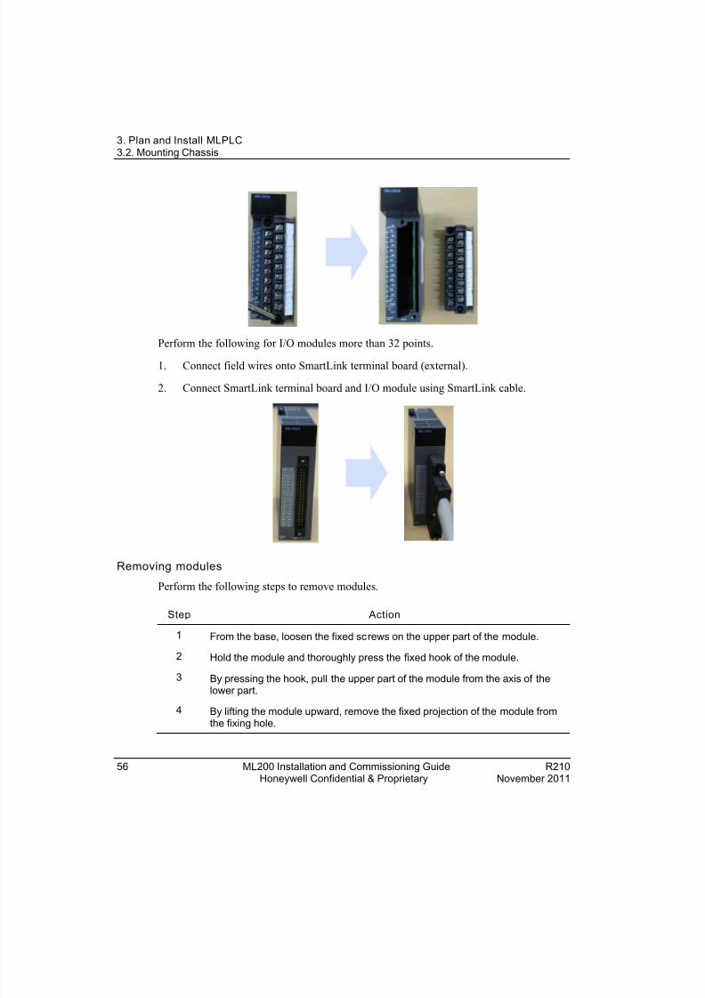
The following image illustrates the modules mounted in the CPU base.

8/19/2019 Ml200 Installation and Commissioning Guide
http://slidepdf.com/reader/full/ml200-installation-and-commissioning-guide 55/92
8/19/2019 Ml200 Installation and Commissioning Guide
http://slidepdf.com/reader/full/ml200-installation-and-commissioning-guide 56/92
3. Plan and Install MLPLC3.2. Mounting Chassis
56 ML200 Installation and Commissioning Guide R210Honeywell Confidential & Proprietary November 2011
Perform the following for I/O modules more than 32 points.
1. Connect field wires onto SmartLink terminal board (external).
2. Connect SmartLink terminal board and I/O module using SmartLink cable.
Removing modules
Perform the following steps to remove modules.
Step Action
1 From the base, loosen the fixed screws on the upper part of the module.
2 Hold the module and thoroughly press the fixed hook of the module.
3 By pressing the hook, pull the upper part of the module from the axis of thelower part.
4 By lifting the module upward, remove the fixed projection of the module fromthe fixing hole.

8/19/2019 Ml200 Installation and Commissioning Guide
http://slidepdf.com/reader/full/ml200-installation-and-commissioning-guide 57/92
3. Plan and Install MLPLC3.3. Achieving the topology
R210 ML200 Installation and Commissioning Guide 57November 2011 Honeywell Confidential & Proprietary
Figure 3-3 Removi ng mo dules
CAUTIONWhile removing the module, press the hook and remove the modulefrom the base. Then, remove the fixed projection of the module fromthe module- fixing hole. If module is detached forcefully, the hook orthe fixed projection of the module may break.
3.3 Achieving the topology Achi evi ng the to po lo gy fo r ML200-IEC
ML 200-IEC Architecture
The following figure provides System Configuration of ML200-IEC with 12 slot base.

8/19/2019 Ml200 Installation and Commissioning Guide
http://slidepdf.com/reader/full/ml200-installation-and-commissioning-guide 58/92
3. Plan and Install MLPLC3.3. Achieving the topology
58 ML200 Installation and Commissioning Guide R210Honeywell Confidential & Proprietary November 2011
Figure 3-4 ML200-IEC Architecture

8/19/2019 Ml200 Installation and Commissioning Guide
http://slidepdf.com/reader/full/ml200-installation-and-commissioning-guide 59/92
3. Plan and Install MLPLC3.3. Achieving the topology
R210 ML200 Installation and Commissioning Guide 59November 2011 Honeywell Confidential & Proprietary
ATTENTION
• The base has its base number as ‘0’ and the expansion base has aswitch to set the base number.
• The module starts operating once the the module type and I/O parameterare set using SoftMaster and the correct module type is mounted on thebase.
Connecting the Terminating resistance
If a system requires the main base and the expansion base to be connected, the
terminating resistance must be attached to the expansion connector (OUT) of the lastexpansion base. The terminal resistance is not required to be installed, if the system hasonly the main (without expansion bases).
1. Structure
2. Installation Position

8/19/2019 Ml200 Installation and Commissioning Guide
http://slidepdf.com/reader/full/ml200-installation-and-commissioning-guide 60/92
3. Plan and Install MLPLC3.3. Achieving the topology
60 ML200 Installation and Commissioning Guide R210Honeywell Confidential & Proprietary November 2011
Figure 3-5 Installation poin t of terminatin g resistor
Configuring the Dip switch settings
The following table lists the different types of switches in ML200-IEC.
Table 3-2 ML200-IEC Dip swit ch setting
Switches Description
Boot/Nor switches Downloads new operating system or upgrades CPUfirmware before releasing the product.
• ON (right): For normal CPU operation mode.
• OFF (left): Downloads new operating system. It isreserved for use by Honeywell factory / authorizedpersonnel. Switching to this position by user is strictly
prohibited.Note : Both Boot/Nor switches must always be set to ON(right) position. Setting it to OFF (left) position may causeabnormal operation or damage to modules.

8/19/2019 Ml200 Installation and Commissioning Guide
http://slidepdf.com/reader/full/ml200-installation-and-commissioning-guide 61/92
3. Plan and Install MLPLC3.3. Achieving the topology
R210 ML200 Installation and Commissioning Guide 61November 2011 Honeywell Confidential & Proprietary
REMOTE enable switch Enables the PLC to operate remotely.
• ON (right): All functions enabled for remote control
• OFF (left): Limited remote functions
M.XCHG (Moduleexchange switch)
To change a module online during CPU operation (hot-swapping).
• ON (right): Before changing the module, put the switchin ON position.
• OFF (left): After the module is changed put the switchback to OFF position.
RUN/STOP mode Switch Sets the operation mode of CPU module.
• STOP → RUN: executes the program
• RUN → STOP: stops the program
These commands operate irrespective of the REMOTEswitch setting.
Reset/ D.Clear Switch • If this switch is moved to:
− left and returned to center - executes RESETaction.
− left and held for more than 3seconds, thenreturned to center: executes Overall RESETaction.
• If this switch is moved to:
− Right and pressed - it executes DATA CLEARaction.
− Right and returned to center - clear Latch 1 areadata and general data area.
− Right, held for more than 3s and then returned tocenter it clears Latch 2 area data and generaldata area.
Note : DATA CLEAR acts only in “STOP” operationmode.
Achi evi ng th e to po lo gy fo r ML200R
ML200R has a redundant system for CPU, power supply, and communication modules.

8/19/2019 Ml200 Installation and Commissioning Guide
http://slidepdf.com/reader/full/ml200-installation-and-commissioning-guide 62/92
3. Plan and Install MLPLC3.3. Achieving the topology
62 ML200 Installation and Commissioning Guide R210Honeywell Confidential & Proprietary November 2011
Install two identical sets of main bases consisting of same power supply, CPU, andcommunication modules and connect two CPU modules with synchronization cable.
One of the two CPU modules is a master system in control of main operation and anotheris a standby system for backup control, if the master fails during operation.
After recovering from a fault, ex-Master CPU can be operated as a standby system andyou can switch the master with a programming tool or a key switch.
You can select CPU side by a switch on the CPU module (that is, A or B) and duplicationof sides gives an error.
The main base comprises of the following modules.
Item Model
Main Base
CPU 2MLR-CPUH/T, 2MLR-CPUH/F
Power supply 2MLR-AC12, 2MLR-AC22, 2MLR-AC13, 2MLR- AC23, 2MLR-DC42
Communication FEnet
Base 2MLR-M02P, 2MLR-M06P
Sync cable 2MLC-F201
ExpansionBase
Digital I/O All types of digital I/O
Analog I/O All types of analog I/O
CommunicationModule Pnet/Dnet/Snet I/F module
Power supply redundancy
Redundant power supply can be installed in both main and expansion bases. When one ofthe power supplies fails to operate, the system can seamlessly operate with another powersupply. Faulty power supply module can be repaired during operation.
I/O bus r edundancy
Expansion bases and cables can be configured as a ring topology so that singlecommunication cable fault does not stop the system and the operation continues withanother cable attached to the system.
8/19/2019 Ml200 Installation and Commissioning Guide
http://slidepdf.com/reader/full/ml200-installation-and-commissioning-guide 63/92
3. Plan and Install MLPLC3.3. Achieving the topology
R210 ML200 Installation and Commissioning Guide 63November 2011 Honeywell Confidential & Proprietary
In a normal ring configuration, the communication is enabled to the path nearest tomaster CPU.
ATTENTION
• CPU module cannot be installed in the expansion base.
• Both CPU modules must have the same operating system version.
• The configuration of both the CPU modules must be in the samesequence. Example: If 2MLL-EFMT is installed in the slot 0 of CPU-A,2MLL-EFMT in the CPU-B must be installed in the slot 0.
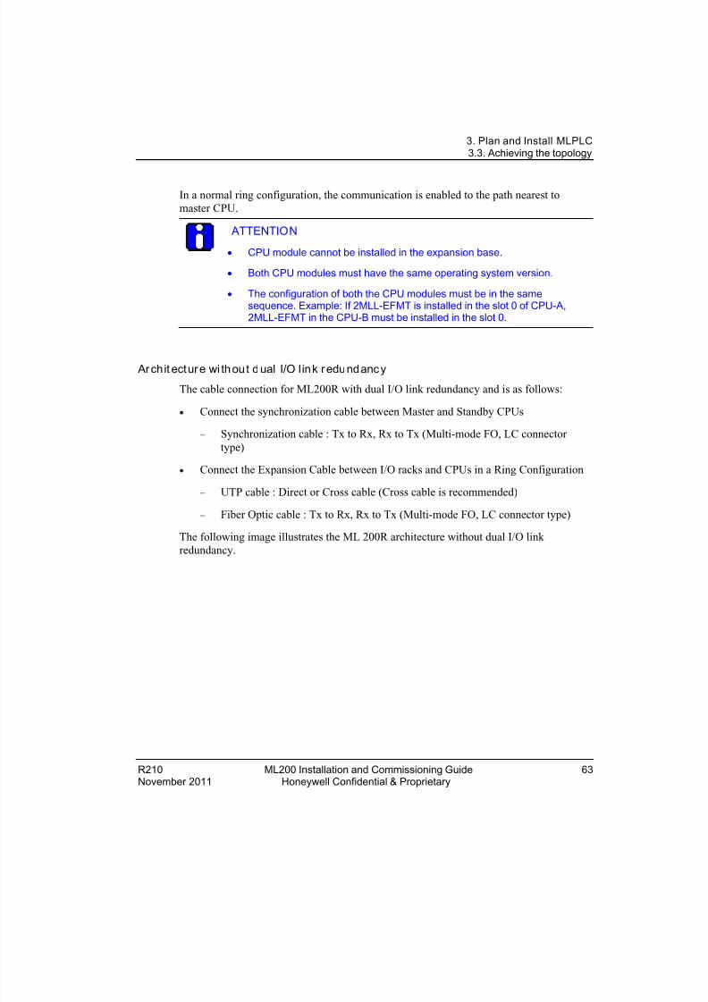
Ar chit ectur e wi th ou t d ual I/O link r edundanc y
The cable connection for ML200R with dual I/O link redundancy and is as follows:
• Connect the synchronization cable between Master and Standby CPUs
− Synchronization cable : Tx to Rx, Rx to Tx (Multi-mode FO, LC connectortype)
• Connect the Expansion Cable between I/O racks and CPUs in a Ring Configuration
− UTP cable : Direct or Cross cable (Cross cable is recommended)
− Fiber Optic cable : Tx to Rx, Rx to Tx (Multi-mode FO, LC connector type)
The following image illustrates the ML 200R architecture without dual I/O linkredundancy.
8/19/2019 Ml200 Installation and Commissioning Guide
http://slidepdf.com/reader/full/ml200-installation-and-commissioning-guide 64/92
3. Plan and Install MLPLC3.3. Achieving the topology
64 ML200 Installation and Commissioning Guide R210Honeywell Confidential & Proprietary November 2011
Figure 3-6 ML200R archit ecture with out d ual I/O link redundancy
Arch it ectur e wi th dual I/O li nk red undancy
The cable connection for ML200R with dual I/O link redundancy and is as follows:
• Connect the synchronization cable between Master and Standby CPUs
− Synchronization cable : Tx to Rx, Rx to Tx (Multi-mode FO, LC connectortype)
• Connect the Expansion Cable between I/O racks and CPUs in a Ring Configuration
− UTP cable : Direct or Cross cable (Cross cable is recommended)
− Fiber Optic cable : Tx to Rx, Rx to Tx (Multi-mode FO, LC connector type)
The following image illustrates the ML200R architecture with dual I/O link redundancy.

8/19/2019 Ml200 Installation and Commissioning Guide
http://slidepdf.com/reader/full/ml200-installation-and-commissioning-guide 65/92
3. Plan and Install MLPLC3.3. Achieving the topology
R210 ML200 Installation and Commissioning Guide 65November 2011 Honeywell Confidential & Proprietary
Figure 3-7 ML200R archit ecture with dual I/O link r edundancy
ATTENTION
The images illustrate the architecture of 2MLR-CPUH/T (Electrical). Thearchitecture remains the same for 2MLR-CPUH/F (optic fiber).
The following table describes the topology of ML200R.
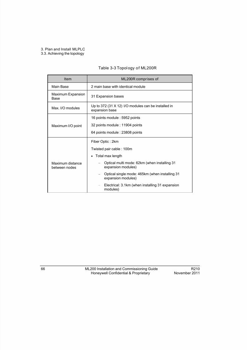
8/19/2019 Ml200 Installation and Commissioning Guide
http://slidepdf.com/reader/full/ml200-installation-and-commissioning-guide 66/92
3. Plan and Install MLPLC3.3. Achieving the topology
66 ML200 Installation and Commissioning Guide R210Honeywell Confidential & Proprietary November 2011
Table 3-3 Topol ogy o f ML200R
Item ML200R compr ises of
Main Base 2 main base with identical module
Maximum ExpansionBase 31 Expansion bases
Max. I/O modules Up to 372 (31 X 12) I/O modules can be installed inexpansion base
Maximum I/O point
16 points module : 5952 points
32 points module : 11904 points
64 points module : 23808 points
Maximum distancebetween nodes
Fiber Optic : 2km
Twisted pair cable : 100m
• Total max length
− Optical multi mode: 62km (when installing 31expansion modules)
− Optical single mode: 465km (when installing 31expansion modules)
− Electrical: 3.1km (when installing 31 expansionmodules)
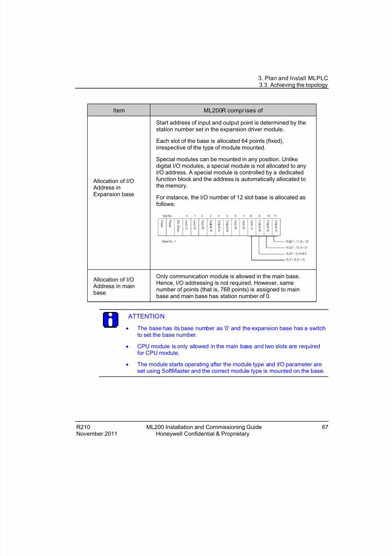
8/19/2019 Ml200 Installation and Commissioning Guide
http://slidepdf.com/reader/full/ml200-installation-and-commissioning-guide 67/92
3. Plan and Install MLPLC3.3. Achieving the topology
R210 ML200 Installation and Commissioning Guide 67November 2011 Honeywell Confidential & Proprietary
Item ML200R compr ises of
Allocation of I/O Address in
Expansion base
Start address of input and output point is determined by thestation number set in the expansion driver module.
Each slot of the base is allocated 64 points (fixed),irrespective of the type of module mounted.
Special modules can be mounted in any position. Unlikedigital I/O modules, a special module is not allocated to anyI/O address. A special module is controlled by a dedicatedfunction block and the address is automatically allocated tothe memory.
For instance, the I/O number of 12 slot base is allocated asfollows:
Allocation of I/O Address in mainbase
Only communication module is allowed in the main base.Hence, I/O addressing is not required. However, same
number of points (that is, 768 points) is assigned to mainbase and main base has station number of 0.
ATTENTION
• The base has its base number as ‘0’ and the expansion base has a switchto set the base number.
• CPU module is only allowed in the main base and two slots are requiredfor CPU module.
• The module starts operating after the module type and I/O parameter areset using SoftMaster and the correct module type is mounted on the base.

8/19/2019 Ml200 Installation and Commissioning Guide
http://slidepdf.com/reader/full/ml200-installation-and-commissioning-guide 68/92
3. Plan and Install MLPLC3.3. Achieving the topology
68 ML200 Installation and Commissioning Guide R210Honeywell Confidential & Proprietary November 2011
Example of mixed topology (combination of electric and optic fiber)
ML200R with dual I/O link redundancy using mixed modules.
In a system, the optical modules can be used in the following two cases. This helps to build an optical/electrical mixed module network without an additional converter.
• When the distance between electrically established stations is more.
• Electrical noise is severe.
2MLR-CPUH/T for both CPUs and 2MLR-DBDT and 2MLR-DBDH for expansiondrive module.
Configuring the Dip switch settings
The following table lists the different types of switches in ML200R.

8/19/2019 Ml200 Installation and Commissioning Guide
http://slidepdf.com/reader/full/ml200-installation-and-commissioning-guide 69/92
3. Plan and Install MLPLC3.4. Power on and start up
R210 ML200 Installation and Commissioning Guide 69November 2011 Honeywell Confidential & Proprietary
Table 3-4 ML200R Dip sw itch settings
Switches Description
BOOT/NORMAL switch Downloads new operating system or upgrades CPUfirmware before releasing the product.
• ON (right): For normal CPU operation mode.
• OFF (left): Downloads new operating system. It isreserved for use by Honeywell factory / authorizedpersonnel. Switching to this position by user is s trictlyprohibited.
Note : Both Boot/Nor switches must always be set to ON(right) position. Setting it to OFF (left) position may causeabnormal operation or damage to modules.
A/B side switch (CPUposition designationswitch)
Defines CPU classification
• CPU module is ‘A’, if the switch is set to the left.
• CPU module is ‘B’, if the switch is set to the right.
• Two CPU must have different settings (you can checkit using software).
• A same setting does not affect operation but may notoperate in a normal way.
Reset/D. Clear switch Resets CPU when switch is set to the left.
• Left → Center: RESET
• Left → more than 3s → Center: Overall RESET
Clears data when switch is set to the right.
• Right → Center: clears memory area for M, auto-allocated retain, general data memory address.
• Right → more than 3s → Center: Clears memory areafor M, auto allocated retain, General Data Memory
Address and R Area
Note : Data clear is only performed in ‘STOP’ mode.

8/19/2019 Ml200 Installation and Commissioning Guide
http://slidepdf.com/reader/full/ml200-installation-and-commissioning-guide 70/92
3. Plan and Install MLPLC3.4. Power on and start up
70 ML200 Installation and Commissioning Guide R210Honeywell Confidential & Proprietary November 2011
3.4 Power on and start upDepending on the CPU types used, verify the following before power on and start up ofthe system.
• Ensure that the modules are mounted correctly in both the CPU base and the I/O base.
• Ensure the following:
− Synchronization cable is connected between Master and Standby CPUs.
− Expansion cable is connected between I/O racks and CPUs in a Ring
Configuration.
• Ensure that both the CPUs are set to different CPU sides, if not perform thefollowing to set the CPU sides.
− To set the CPU to side A move the switch to left and release.
− To set the CPU to side B move the switch to right and release.
ATTENTION
DO NOT change Boot/Normal switch settings.
• Ensure that the STATION NUMBER is set using the Rotary switch on the
Expansion driver module.
I/O device wirin g
Perform the following steps for I/O device wiring.
1. The cable used for I/O wiring must be 0.3~2.0mm 2.
2. Use a separate input and output cable for wiring.
3. I/O signal cable must be separated by a distance of at least 100mm from the maincircuit cable of high voltage/high current.
4. If it is not possible to separate the main circuit cable and power cable, use theshielded cable in all cases and ground the PLC.

8/19/2019 Ml200 Installation and Commissioning Guide
http://slidepdf.com/reader/full/ml200-installation-and-commissioning-guide 71/92
3. Plan and Install MLPLC3.4. Power on and start up
R210 ML200 Installation and Commissioning Guide 71November 2011 Honeywell Confidential & Proprietary
5. In case of pipe wiring, check the pipe for grounding properly.
6. Separate output cable of DC 24V from AC 110V cable or AC 220V cable.
ATTENTION
Current leakage may occur if the wiring is connected for distances greaterthan 200m. This may be caused by the capacitance.
Power w iring
Perform the following steps for power wiring.
1. Connect a voltage regulated transformer, if the power variance is higher than thespecified range.
2. In case of excessive interference (noise), use an isolation transformer.
The following figure illustrates the distributions of AC 220V for PLC Power Supply, I/O
Modules, and other Main Circuit Equipment.

8/19/2019 Ml200 Installation and Commissioning Guide
http://slidepdf.com/reader/full/ml200-installation-and-commissioning-guide 72/92
3. Plan and Install MLPLC3.4. Power on and start up
72 ML200 Installation and Commissioning Guide R210Honeywell Confidential & Proprietary November 2011
3. While using power module of DC 24V output:
a) Do not connect the module, in parallel with the output of several powermodules.
b) If DC 24V output capacity of a power module is not sufficient for the PLC I/Omodules, supply the external DC 24V power, as displayed in the followingfigure.
4. AC 110V/AC 220V/DC 24V cables must be properly twisted and connected withthe shortest distance.
5. AC 110V/AC 220V cable must be as thick as possible (2mm2), to reduce voltage
drop. AC 110V/ DC 24V cables must not be installed close to main circuit cable(high voltage/high current) and I/O signal cable. They must be 100mm away fromsuch cables.

8/19/2019 Ml200 Installation and Commissioning Guide
http://slidepdf.com/reader/full/ml200-installation-and-commissioning-guide 73/92
3. Plan and Install MLPLC3.4. Power on and start up
R210 ML200 Installation and Commissioning Guide 73November 2011 Honeywell Confidential & Proprietary
6. Use a surge absorber as a protection against lightning, as displayed in the followingfigure.
TIP
1. Separate PLC earth (E2) from earth (E1) of surge absorber againstlightning.
2. In case of an increase in voltage, the surge absorber ensures that it doesnot increase more than the predefined maximum limit.
3. Use a shielded isolation transformer or noise filter in areas where highernoise levels are expected.
4. It is advisable to use twisted cable for input power. Ensure that the
shielded transformer or noise filter wiring does not pass the duct.
Module LEDs
LED indicators for ML200-IEC
The following table describes the LED indicators for ML200-IEC.
Table 3-5 LED indi cator s fo r ML200-IEC
LED Description
RUN/STOP LED
Specifies the operation status of CPU module.
• Green light: Implies CPU operation is in ‘RUN’ mode either by any of thefollowing:
− ‘RUN/STOP’ switch in CPU set to RUN mode.
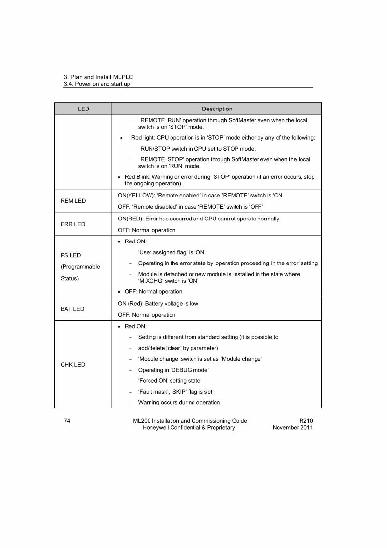
8/19/2019 Ml200 Installation and Commissioning Guide
http://slidepdf.com/reader/full/ml200-installation-and-commissioning-guide 74/92
3. Plan and Install MLPLC3.4. Power on and start up
74 ML200 Installation and Commissioning Guide R210Honeywell Confidential & Proprietary November 2011
LED Description
− REMOTE ‘RUN’ operation through SoftMaster even when the localswitch is on ‘STOP’ mode.
• Red light: CPU operation is in ‘STOP’ mode either by any of the following:
− RUN/STOP switch in CPU set to STOP mode.
− REMOTE ‘STOP’ operation through SoftMaster even when the localswitch is on ‘RUN’ mode.
• Red Blink: Warning or error during ‘STOP’ operation (if an error occurs, stopthe ongoing operation).
REM LEDON(YELLOW): ‘Remote enabled’ in case ’REMOTE’ switch is ‘ON’
OFF: ‘Remote disabled’ in case ‘REMOTE’ switch is ‘OFF’
ERR LEDON(RED): Error has occurred and CPU cannot operate normally
OFF: Normal operation
PS LED
(Programmable
Status)
• Red ON:
− ‘User assigned flag’ is ‘ON’
− Operating in the error state by ‘operation proceeding in the error’ setting
− Module is detached or new module is installed in the state where‘M.XCHG‘ switch is ‘ON’
• OFF: Normal operation
BAT LEDON (Red): Battery voltage is low
OFF: Normal operation
CHK LED
• Red ON:
− Setting is different from standard setting (it is possible to
− add/delete [clear] by parameter)
− ‘Module change’ switch is set as ‘Module change’
− Operating in ‘DEBUG mode’
− ‘Forced ON’ setting state
− ‘Fault mask’, ‘SKIP’ flag is set
− Warning occurs during operation
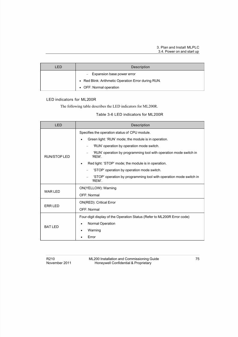
8/19/2019 Ml200 Installation and Commissioning Guide
http://slidepdf.com/reader/full/ml200-installation-and-commissioning-guide 75/92
3. Plan and Install MLPLC3.4. Power on and start up
R210 ML200 Installation and Commissioning Guide 75November 2011 Honeywell Confidential & Proprietary
LED Description
− Expansion base power error
• Red Blink: Arithmetic Operation Error during RUN.
• OFF: Normal operation
LED indicators for ML200R
The following table describes the LED indicators for ML200R.
Table 3-6 LED indicators for ML200R
LED Description
RUN/STOP LED
Specifies the operation status of CPU module.
• Green light: ‘RUN’ mode; the module is in operation.
− ‘RUN’ operation by operation mode switch.
− ‘RUN’ operation by programming tool with operation mode switch in‘REM’.
• Red light: ‘STOP’ mode; the module is in operation.
− ‘STOP’ operation by operation mode switch.
− ‘STOP’ operation by programming tool with operation mode switch in‘REM’.
WAR LEDON(YELLOW): Warning
OFF: Normal
ERR LEDON(RED): Critical Error
OFF: Normal
BAT LED
Four-digit display of the Operation Status (Refer to ML200R Error code)
• Normal Operation
• Warning
• Error
8/19/2019 Ml200 Installation and Commissioning Guide
http://slidepdf.com/reader/full/ml200-installation-and-commissioning-guide 76/92
3. Plan and Install MLPLC3.4. Power on and start up
76 ML200 Installation and Commissioning Guide R210Honeywell Confidential & Proprietary November 2011
Module state transition
The ML200-IEC and ML200R have three operation modes. Each mode describes theoperation process of the PLCs.
• RUN mode
• STOP mode
• DEBUG mode
ATTENTION
Refer to ML200 CPU and SoftMaster User’s Guide for further informationabout module state transition.
Changing operation mode
The following methods are used to change the operation mode.
• Using the mode key of the CPU module.
• Using the programming tool (SoftMaster).
• Using SoftMaster to change the operation mode of a remote CPU module networkedwith the main CPU.
• Using a networked SoftMaster, HMI and the computer link module.• Using the ‘STOP’ command, while a program is operating.
WARNING
Changing the operation mode can energize the field and may cause seriousinjury to users.
Settin g operation mode
The operation mode for ML200-IECcan is set as follows:
Operation modeswitch
Remote switc h SoftMastercommand
Operation mode
RUN X X Run
Stop On Run Remote Run

8/19/2019 Ml200 Installation and Commissioning Guide
http://slidepdf.com/reader/full/ml200-installation-and-commissioning-guide 77/92
3. Plan and Install MLPLC3.4. Power on and start up
R210 ML200 Installation and Commissioning Guide 77November 2011 Honeywell Confidential & Proprietary
Stop Remote Stop
Debug Debug Run
Off Mode change Transfer (changed)operation mode
RUN → STOP X - Stop
• Remote mode can be changed with ‘Remote: On’ and ‘Mode switch: Stop’
• To change the remote ‘RUN’ mode to ‘Stop’ by switch, move the switch (STOP) > RUN >STOP.
ATTENTION
While changing the remote ‘RUN’ mode to ‘RUN’ mode using the switch, thePLC operates continuously without suspension.
Editing during RUN is possible in the ‘RUN’ mode by switch, but the modechange is restricted by SoftMaster.
Change the mode only when the mode change is not remotely allowed.
The operation mode for ML200R can be set as follows:
Mode Key Switch Operation Mode
RUN Local RUN
STOP Local STOP
STOP → REM Remote STOP
REM → RUN Local RUN
RUN → REM Remote RUN
REM → STOP Local STOP
Starting the system
Perform the following to start the system.
1. Connect power cables to power supply modules and supply the power to thesystem.

8/19/2019 Ml200 Installation and Commissioning Guide
http://slidepdf.com/reader/full/ml200-installation-and-commissioning-guide 78/92
3. Plan and Install MLPLC3.4. Power on and start up
78 ML200 Installation and Commissioning Guide R210Honeywell Confidential & Proprietary November 2011
2. Check the LED status of CPU module
− LNK : ON
− RING : ON
− CPU-A/CPU-B : ON
− RED : ON
− MASTER : one of A/B Side is ON
− ACT and LINK : Blink (At least one of two ports should blink)
3. Check the LED status of Expansion drive module
− RUN : ON
− I/F : ON
− RING : ON
− Tx/Rx and LINK : ON (At least one of two ports should blink)
ATTENTION
When the system is started for the first time an error may appear. Rectify theerrors and bring the PLC to Run state. Check and ensure that the LED statusof the CPU module and Expansion drive module is as listed previously. Forfurther information on troubleshooting, refer to the section Troubleshooting.

8/19/2019 Ml200 Installation and Commissioning Guide
http://slidepdf.com/reader/full/ml200-installation-and-commissioning-guide 79/92
R210 ML200 Installation and Commissioning Guide 79November 2011 Honeywell Confidential & Proprietary
4. Troubleshooting
4.1 OverviewThis chapter describes types of potential errors that occur while operating the system,causes of errors, ways to detect them, and corrective measures.
4.2 Basic troubleshooting procedureTo improve the reliability of a system, it is important to take corrective measures
promptly, when a trouble/fault occurs. To recover the system from the fault immediately,
it is most important to quickly detect the potential causes of a fault and take correctivemeasures. To troubleshoot the system correctly, ensure the following cautions and procedures are followed:
1. Check the following manually.
a) Operation status (Stop and Run).
b) Power On/Off status.
c) I/O device status.
d) Wiring status (I/O wiring, expansion, and communication cable).
e) The status of each displays (POWER LED, RUN/STOP LED, I/O LED, andso on), connect to peripherals, and check the operation condition and program.
2. Check for any abnormality.
Observe how a fault changes by executing the following:
a) Move the key switch to STOP and turn it On/Off.
3. Restricting range.
Estimate by which factor, a fault occurs:
a) Is it from the PLC or external factor?
b) I/O module or others?
c) PLC program?

8/19/2019 Ml200 Installation and Commissioning Guide
http://slidepdf.com/reader/full/ml200-installation-and-commissioning-guide 80/92
4. Troubleshooting4.3. Cases and remedies for failures
80 ML200 Installation and Commissioning Guide R210Honeywell Confidential & Proprietary November 2011
4.3 Cases and remedies for failuresTrouble types and measures of input circuit
The followings table describes the examples of common faults and the recommendedmeasures.
Phenomena Causes Measures
Input signalcannot be off
Leakage current of an external device
(if operating by proximate switch andothers)
• Connect a proper resistance orcapacitor so that the voltagebetween terminals of inputmodule is less than the returnvoltage.
• CR value is determined by thevalue of leakage current.
− Recommended value C :0.1 ~ 0.47 µF
R : 47 ~ 120 Ω (1/2W)
• Alternatively, separate a circuitcompletely and install anotherdisplay circuit.
Input signalcannot be off(it must bethat a neonlamp is stillon)
Leakage current of an external device(operation by a limit switch with neonlamp)
Input signalcannot be off
Leakage current from the capacitybetween wires of wiring cable
• Install the power on anexternal device as in thefollowing figure.
Input signalcannot be off
Leakage current of an external device(operation by a switch with LED mark)
• Connect a proper resistanceso that the voltage betweeninput module terminal andcommon terminal is higherthan off voltage as in the

8/19/2019 Ml200 Installation and Commissioning Guide
http://slidepdf.com/reader/full/ml200-installation-and-commissioning-guide 81/92
4. Troubleshooting4.3. Cases and remedies for failures
R210 ML200 Installation and Commissioning Guide 81November 2011 Honeywell Confidential & Proprietary
Phenomena Causes Measures
following figure.
Input signalcannot be off
• Circulating current by using pluraldifferent power sources
• Change plural to singularpower
• Connecting to a circulatingcurrent preventive diode(following figure)
Trouble types and measures of output circuit
The followings table describes the examples of common faults and the recommendedmeasure.
Phenomena Causes Measures
Excessive voltage isallowed to load whenoutput contact is off
• If load contains half-waverectification (solenoid valvemay have it)
• If the polarity is ←, C is chargedwhile the voltage + powervoltage charged to C is allowedto both ends of diode (D). Whenthe polarity is ↑. The maximumvoltage is approximately. 2 √2.
• Connect a dozen ~several hundreds k Ω resistor to a load inparallel.

8/19/2019 Ml200 Installation and Commissioning Guide
http://slidepdf.com/reader/full/ml200-installation-and-commissioning-guide 82/92
4. Troubleshooting4.3. Cases and remedies for failures
82 ML200 Installation and Commissioning Guide R210Honeywell Confidential & Proprietary November 2011
Phenomena Causes Measures
Note: when using it as describedpreviously, the output elementdoes not have any problem but theperformance of diode (D) in loadmay be reduced, probably causinga trouble.
Load cannot be off • Leakage current from surgeabsorbing circuit connected toan output element in parallel.
• Connect a dozen of k Ω resistor or C-R of whichimpedance is equal to theresistance to load in
parallel. Note: If the lengthof wiring from outputmodule to load is long, itmay have leakage currentfrom capacity of cables.
Abnormal time whenload is a C-R typetimer
• Leakage current from surgeabsorbing circuit connected toan output element in parallel.
• Operate the C-R typetimer by mediating a relay.
• Use other one but a C -Rtype timer.
Note: A timer’s internal circuitmay have half-waverectification.
Load cannot be off(DC)
• Circulating current resultingfrom two different powersource
• Adjusting plural to singularpower source.
• Connecting to circulatingcurrent preventive diode(refer to the followingfigure)

8/19/2019 Ml200 Installation and Commissioning Guide
http://slidepdf.com/reader/full/ml200-installation-and-commissioning-guide 83/92
4. Troubleshooting4.3. Cases and remedies for failures
R210 ML200 Installation and Commissioning Guide 83November 2011 Honeywell Confidential & Proprietary
Phenomena Causes Measures
• It circulates if E1< E2.
• It circulates even when E1 isOff (E2 is On).
Off response fromload takes a longertime
• Over current at Off
If a large current load such as
solenoid, (time constant L/R islarge) is directly operated bytransistor output.
• Since current is allowedthrough diode when transistoroutput is off, it may bedelayed for 1s and longer
depending on load.
• Insert a magneticconnector and others forwhich time constant is
small as presented in thefigure and operate load bythe contact
Output transistor isdestructed
• Inrush current of glow lamp
As soon as it lights up, it may have10 times higher inrush current.
• To restrict inrush current, itmust allow dark currentthat is 1/3 ~ 1/5 of therated current of glow lamp.
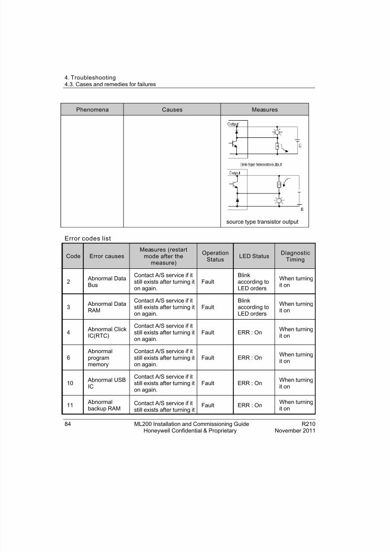
8/19/2019 Ml200 Installation and Commissioning Guide
http://slidepdf.com/reader/full/ml200-installation-and-commissioning-guide 84/92
4. Troubleshooting4.3. Cases and remedies for failures
84 ML200 Installation and Commissioning Guide R210Honeywell Confidential & Proprietary November 2011
Phenomena Causes Measures
source type transistor output
Error codes list
Code Error causesMeasures (restart
mode after themeasure)
OperationStatus LED Status Diagnostic
Timing
2 Abnormal DataBus
Contact A/S service if itstill exists after turning it
on again.
FaultBlinkaccording to
LED orders
When turningit on
3 Abnormal DataRAM
Contact A/S service if itstill exists after turning iton again.
FaultBlinkaccording toLED orders
When turningit on
4 Abnormal ClickIC(RTC)
Contact A/S service if itstill exists after turning iton again.
Fault ERR : On When turningit on
6 Abnormalprogrammemory
Contact A/S service if itstill exists after turning iton again.
Fault ERR : On When turningit on
10 Abnormal USB
IC
Contact A/S service if itstill exists after turning iton again.
Fault ERR : On When turning
it on
11 Abnormalbackup RAM
Contact A/S service if itstill exists after turning it
Fault ERR : On When turningit on
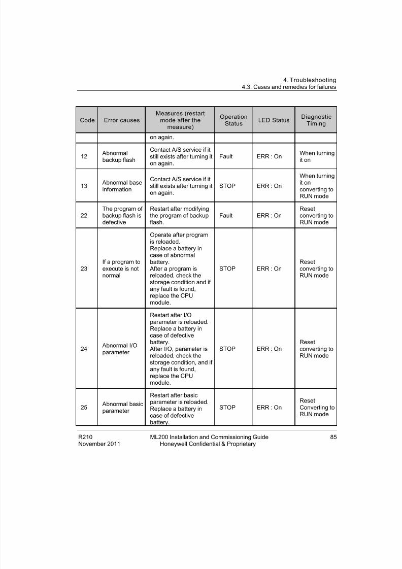
8/19/2019 Ml200 Installation and Commissioning Guide
http://slidepdf.com/reader/full/ml200-installation-and-commissioning-guide 85/92
4. Troubleshooting4.3. Cases and remedies for failures
R210 ML200 Installation and Commissioning Guide 85November 2011 Honeywell Confidential & Proprietary
Code Error causesMeasures (restart
mode after themeasure)
OperationStatus LED Status Diagnostic
Timing
on again.
12 Abnormalbackup flash
Contact A/S service if itstill exists after turning iton again.
Fault ERR : On When turningit on
13 Abnormal baseinformation
Contact A/S service if itstill exists after turning iton again.
STOP ERR : On
When turningit onconverting toRUN mode
22The program ofbackup flash isdefective
Restart after modifyingthe program of backupflash.
Fault ERR : OnResetconverting toRUN mode
23If a program toexecute is notnormal
Operate after programis reloaded.Replace a battery incase of abnormalbattery.
After a program isreloaded, check thestorage condition and ifany fault is found,replace the CPUmodule.
STOP ERR : OnResetconverting toRUN mode
24 Abnormal I/Oparameter
Restart after I/Oparameter is reloaded.Replace a battery incase of defectivebattery.
After I/O, parameter isreloaded, check thestorage condition, and ifany fault is found,replace the CPUmodule.
STOP ERR : OnResetconverting toRUN mode
25 Abnormal basicparameter
Restart after basicparameter is reloaded.Replace a battery incase of defectivebattery.
STOP ERR : OnResetConverting toRUN mode
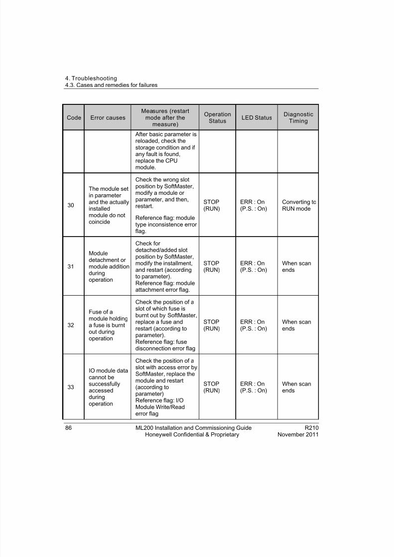
8/19/2019 Ml200 Installation and Commissioning Guide
http://slidepdf.com/reader/full/ml200-installation-and-commissioning-guide 86/92
4. Troubleshooting4.3. Cases and remedies for failures
86 ML200 Installation and Commissioning Guide R210Honeywell Confidential & Proprietary November 2011
Code Error causesMeasures (restart
mode after themeasure)
OperationStatus LED Status Diagnostic
Timing
After basic parameter isreloaded, check thestorage condition and ifany fault is found,replace the CPUmodule.
30
The module setin parameterand the actuallyinstalledmodule do notcoincide
Check the wrong slotposition by SoftMaster,
modify a module orparameter, and then,restart.
Reference flag: moduletype inconsistence errorflag.
STOP(RUN)
ERR : On(P.S. : On)
Converting toRUN mode
31
Moduledetachment ormodule additionduringoperation
Check fordetached/added slotposition by SoftMaster,modify the installment,and restart (accordingto parameter).Reference flag: module
attachment error flag.
STOP(RUN)
ERR : On(P.S. : On)
When scanends
32
Fuse of amodule holdinga fuse is burntout duringoperation
Check the position of aslot of which fuse isburnt out by SoftMaster,replace a fuse andrestart (according toparameter).Reference flag: fusedisconnection error flag
STOP(RUN)
ERR : On(P.S. : On)
When scanends
33
IO module datacannot besuccessfully
accessedduringoperation
Check the position of aslot with access error bySoftMaster, replace themodule and restart(according toparameter)Reference flag: I/OModule Write/Readerror flag
STOP
(RUN)
ERR : On
(P.S. : On)
When scan
ends

8/19/2019 Ml200 Installation and Commissioning Guide
http://slidepdf.com/reader/full/ml200-installation-and-commissioning-guide 87/92
4. Troubleshooting4.3. Cases and remedies for failures
R210 ML200 Installation and Commissioning Guide 87November 2011 Honeywell Confidential & Proprietary
Code Error causesMeasures (restart
mode after themeasure)
OperationStatus LED Status Diagnostic
Timing
34
Special/linkmodule datacannot besuccessfullyaccessedduringoperation
Check the position of aslot with access error bySoftMaster, replace themodule, and restart(according toparameter).Reference flag:Special/Link Moduleinterface error
STOP(RUN)
ERR : On(P.S. : On)
When scanends
39
CPU isincompletelyclosed or introuble
System is closedabnormally due to noiseor abnormal hardware1) Contact A/S service ifit still exists after turningit on again.2) Take a measureagainst noise.
STOP RUN: OnERR : On Always
40
The scan timeof a programexceeds thescan delaywatchdog timedesignated byparameterduringoperation
Check the scan delaywatchdog timedesignated by
parameter, modifyparameter or program,and restart.
STOP RUN: On
ERR : On
Whenprogram isexecuted
41Operation errorwhile executinguser program
Eliminating an operationerror reload theprogram and restart(check).
If STOP: Check thedetails of operationerror by SoftMaster andmodify the programIf RUN: refer to the error
steps of F area.
STOP(RUN)
ERR : On(CHK: blink)
Whenprogram isexecuted
42Exceeding thespecified stackrange during
Restart STOP RUN: OnERR : On
Whenprogram is

8/19/2019 Ml200 Installation and Commissioning Guide
http://slidepdf.com/reader/full/ml200-installation-and-commissioning-guide 88/92
4. Troubleshooting4.3. Cases and remedies for failures
88 ML200 Installation and Commissioning Guide R210Honeywell Confidential & Proprietary November 2011
Code Error causesMeasures (restart
mode after themeasure)
OperationStatus LED Status Diagnostic
Timing
program executed
44 Use of TimerIndex error
Modify the timer indexprogram, reload, andstart.
STOP(RUN)
RUN: OnERR : On
When scanends
50
Error ofexternal device
is detected by auser programduringoperation
Repair a fault device byreferring to error
detection flag ofexternal device andrestart (according toparameter)
STOP(RUN) ERR : On(P.S. : On) When scanends
60E_STOPfunctionexecution
Eliminate the causes oferror operating E_STOPfunction in the programand turn it on again.
STOP RUN: OnERR : On
Whenprogram isexecuted
101 CPU positionerror
CPU is installed atwrong position. Positionthe CPU correctly.
STOP S101 Turn it on
102 DuplicatedCPU ID error
Set the A/B side
switches of master CPUand standby CPUdifferently.
STOP S102 Turn it on
103 Base abnormalerror
Configure expansioncable as ring topologyand position thedetached basecorrectly. Forinformation of detachedbase, refer to CPU errorlog.
STOP,RUN E103 Execute
program
104Systemconfigurationerror
Check for dual IO linkredundancy
configuration and ringtopology
• Check redundancydrive module station
STOP E104When scanends, turn iton

8/19/2019 Ml200 Installation and Commissioning Guide
http://slidepdf.com/reader/full/ml200-installation-and-commissioning-guide 89/92
4. Troubleshooting4.3. Cases and remedies for failures
R210 ML200 Installation and Commissioning Guide 89November 2011 Honeywell Confidential & Proprietary
Code Error causesMeasures (restart
mode after themeasure)
OperationStatus LED Status Diagnostic
Timing
number.
• Check operatingsystem version ofexpansion drivemodule andexpansion manager.
300
Redundancysystemsynchronousoperating error.
During redundancyoperating,synchronization erroroccurs
STOP E300
Switch to
redundancyoperation
301
Standby CPUfailed tooperate as
redundancybecause ofmaster CPUerror.
Restart as redundancyoperation
• set operation modeof standby CPU asSTOP.
• cancel the error ofmaster CPU andthen restart.
• change standby CPUinto RUN mode.
Restart standby CPU assingle operation
• Disable master CPU(STOP mode orpower cut)
• restart standby CPUthrough reset switchor by changingoperation mode fromSTOP to RUN.
STOP E301Start standbyoperation
500Data memorybackup is notpossible
Turn it on again if
battery is normal. It isconverted to STOPmode in Remote Mode.
STOP ERR : On Reset

8/19/2019 Ml200 Installation and Commissioning Guide
http://slidepdf.com/reader/full/ml200-installation-and-commissioning-guide 90/92

8/19/2019 Ml200 Installation and Commissioning Guide
http://slidepdf.com/reader/full/ml200-installation-and-commissioning-guide 91/92

8/19/2019 Ml200 Installation and Commissioning Guide
http://slidepdf.com/reader/full/ml200-installation-and-commissioning-guide 92/92