mm1504: powder metallurgy and ceramics
TRANSCRIPT

Powder Characterization
1
Property Method
Particle Size and Size Distribution Sieve Analysis; permeability; sedimentation; electrical resistance; light scattering; microscopy; surface area
Particle Shape (external) SEM; shape parameters; morphological anlysis
Particle Shape (external and internal)
Stereology; porosimetry; gas adsorption
Particle Density Pycnometry; mercury porosimetry
Specific surface area Gas absorption; permeability
Surface Chemistry X-ray photoelectron spectroscopy (XPS); Auger electron spectroscopy; secondary ion mass spectroscopy; ion scattering spectroscopy
Alloy Phases and phase distribution
Optical metallography; stereology; electron microscopy; EDAX; X-ray diffraction
Quality of mixing (segregation) Macroregion: Variability coefficient (by chemical analysis); Microregion: Variability coefficient (2nd comp.>5%);Homogeneity coefficient (2nd comp. <5%; by metallography)

Method of Powder Production and Particle Shape
2

Chemical Composition and Structure
3
❖ Chemical elements or phases present in the metal powders affect the processing and properties of the final
product.
❖ It is necessary to know whether elements are present in the elemental form or chemical compounds.
❖ Impurity elements affect the hardness and chemical reactivity of the metal powders.
❖ Metal powders adsorbs gases and water vapor → formation of surface oxide → entrapment of oxide inside
the sintered material during subsequent compaction and sintering.
❖ Chemical composition can be determined by:
➢ X-ray diffraction
➢ spectrographic techniques
➢ wet analysis
➢ XPS
➢ Auger electron Spectroscopy
➢ EDS/EDX
➢ Secondary Ion mass spectroscopy
Internal Structure:• Micro-porosity: shrinkage or entrapped
gases• Single phase (mono- or poly-crystalline )• Multiphase: number of phases, phase shape
and size, size distribution, spatial distribution of phases, texture, composition

Particle Size and Size Distribution
4
Particle Size Distribution (PSD): Measurement of the size of the population of the particles and describing the proportion of the sample corresponding to a given size (or range of size)
Log Scale
/Individual Particle
/Individual Particle

Particle Size and Size Distribution
5
Particle Size Distribution (PSD): Measurement of the size of the population of the particles and describing the proportion of the sample corresponding to a given size (or range of size)
Log Scale

Particle Size and Size Distribution
6
Sieve AnalysisParticle Size Distribution (PSD): Measurement of the size of the population of the particles and describing the proportion of the sample corresponding to a given size (or range of size)

Particle Size and Size Distribution
7www.microtrac.com
Particle Size and Size Distribution
8
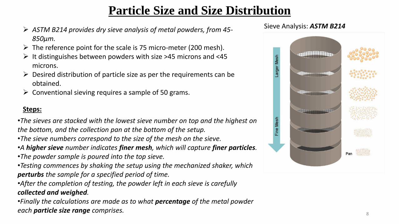
Sieve Analysis: ASTM B214➢ ASTM B214 provides dry sieve analysis of metal powders, from 45-
850µm.➢ The reference point for the scale is 75 micro-meter (200 mesh).➢ It distinguishes between powders with size >45 microns and <45
microns.➢ Desired distribution of particle size as per the requirements can be
obtained.➢ Conventional sieving requires a sample of 50 grams.
•The sieves are stacked with the lowest sieve number on top and the highest on the bottom, and the collection pan at the bottom of the setup. •The sieve numbers correspond to the size of the mesh on the sieve. •A higher sieve number indicates finer mesh, which will capture finer particles.•The powder sample is poured into the top sieve. •Testing commences by shaking the setup using the mechanized shaker, which perturbs the sample for a specified period of time.•After the completion of testing, the powder left in each sieve is carefully collected and weighed. •Finally the calculations are made as to what percentage of the metal powder each particle size range comprises.
Steps:

Particle Size and Size Distribution: Light Scattering Method
9
➢ The powder sample is dispersed in water or a suitable organic liquid.➢ The solution is circulated through a path of a light beam (Laser).➢ The particle pass through the light beam and scatter it.➢ Photodetector arrays collect the scattered light and convert it to electrical
signals.➢ The signals are processed by microprocessor, and converted to size
distribution using Fraunhofer diffraction or Mie Scattering.➢ The analysis assumes spherical model, i.e. the particle size is presented as
equivalent spherical diameter.➢ The particle size ranges from 100 nm to 2000 Micrometer.
www.shimadzu.com

Particle Size and Size Distribution: Dynamic Image Analysis
10
• In contrast to sieve analysis DIA measures the particles in a completely random orientation.
• A variety of size as well as shape parameters are determined based on the particle images.
• Typical size parameters are, for example, breadth, length and diameter of equivalent circle
• Parameters to describe the particle shape include sphericity, symmetry, convexity and aspect ratio.
Larger Particles Complete Particles Smaller Particles

BET Specific Surface Area
11
• The BET (Brunauer, Emmett and Teller) theory is commonly used to evaluate the gas adsorption data and generate a specific surface area result expressed in units of area per mass of sample (m2/g).
• The specific surface area of a material is then determined by the physical adsorption of a gas (typically nitrogen, krypton, or argon) onto the surface of the sample at cryogenic temperatures (typically liquid nitrogen or liquid argon temperatures).
• Once the amount of adsorbate gas has been measured (either by a volumetric or continuous flow technique), calculations which assume a monomolecular layer of the known gas are applied.
• Specific surface area can also be expressed in units of area per volume of sample (m2/cm3). It is obtained by multiplying the BET surface area with the density of the material.
• BET surface area analysis must be done in the linear region of the BET plot.
• It is primarily used for very fine powders, particularly refractory metals, and for characterizing the total surface area of porous powders.

Flow Rate, Apparent and Tap Density (ASTM B212)
12
• The apparent density of a powder refers to the mass of unit volume of loose powder (gm/cm3).
• It determines the size of compaction tooling and extent of press motion required to compacting loose powders.
• It influences the sintering behavior of the powders.• It is determined by Hall flowmeter, where a container of known volume (25
cm3) is completely filled by flowing metal powder through Hall funnel.• Hall Flowmeter determines the apparent density by permitting a volume or
certain quantity of powder in a loose condition to flow from a Carney funnel diameter 0.2 inch/5.0 mm into a specified density cup of definite volume(25 cm³) under controlled conditions. The mass of powder per unit volume (the ratio between the mass and the volume) is recorded and reported as apparent density.
• The flow rate of a powder is determined by Hall Flowmeter, where the time in seconds for 50g of powders to flow through a prescribed small orifice (2.5 mm diameter) is measured. (for free-flowing-powders)
• The flow time reciprocal to the flow rate.• Very fine powders do not flow through small orifice, hence larger orifice (5.0
mm diameter) is used for non-free-flowing powders.

Flow Rate, Apparent and Tap Density (ASTM B212)
13
• volume determined by the use of graduated cylinder, the cylinder can be tapped giving a measure of the so called Tapped Density.
• The tapped density is an increased bulk density attained after mechanically tapping a container containing the powder sample.
• The tapped density is obtained by mechanically tapping a graduated measuring cylinder or vessel containing the powder sample.
• After observing the initial powder volume or mass, the measuring cylinder or vessel is mechanically tapped, and volume or mass readings are taken until little further volume or mass change is observed. The mechanical tapping is achieved by raising the cylinder or vessel and allowing it to drop, under its own mass, a specified distance by either of three methods as described below. Devices that rotate the cylinder or vessel during tapping may be preferred to minimize any possible separation of the mass during tapping down.

Blending Metal Powders
➢Proper mixing is essential to ensure uniformity of mechanical properties throughout the part
➢Powders of different metals can be mixed to impart special physical and mechanical properties
to the P/M product.
➢Lubricants can be mixed with the powders to improve their flow characteristics. They reduce
friction between metal particles, improve flow of the powder metals into the die, and improve die
life. Lubricants are typically stearic acids or zinc stearate in a proportion from 0.25% - 5% by weight.
➢Other additives – binders are used to develop sufficient green strength, and additives also can be used to facilitate sintering.
➢Powders can be mixed in air, in inert atmosphere (to avoid oxidization), or in liquids (which act
as lubricants and make the mix more uniform).
➢Several types of blending equipment are available.

Blending/Mixing Metal Powders
(e)
(a) through (d) Some common bowl geometries for mixing or blending powders. (e) A
mixer suitable for blending metal powders. Since metal powders are abrasive, mixers
rely on the rotation or tumbling of enclosed geometries as opposed to using aggressive
agitators. Source: Courtesy of Gardner Mixers, Inc.

Consolidation of Metallic and ceramic Powders)
16
Purpose of Compaction:
• To consolidate the powders into desired shape.
• Achieving sufficient strength for further processing and handling.
• To impart desired level and type of porosity within the compact. It may be interconnected or isolated
porosity.
• Necessary to achieve desired density and density distribution so that the final shape remains intact and
very close to the final dimensions of the finished product. Sintering leads to shrinkage, densification, and
strengthening.
• Consideration has to be given to the towards tooling in such a way that the dimensional changes during
sintering are accommodated.
• Interconnected Pores: self-lubricating bush bearings, metallic filters, diffusers, distributors.
• Minimum or Zero porosity: Structural parts or machine components requiring maximum strength and
density with fine grain size.

Compacting Methods
17
• Uniaxial Compaction Using Rigid Dies (Cold and Hot)
• Isostatic or Hydrostatic Compaction. (Cold isostatic Pressing)
• Hot Isostatic Pressing (HIP)
• Powder Forging
• Powder Extrusion
• Powder Rolling
• Stepped Pressing
• Slip Casting
• Injection Molding
• High Energy rate Forming (HERF) or Explosive Compaction.
Since there is no plasticity in brittle and ceramic particles, slightly different strategy is adopted during compaction so that the desired compact could be achieved without damaging the tooling.

Compaction
(a) Compaction of metal powder to form a bushing. The pressed-powder part is called
green compact. (b) Typical tool and die set for compacting a spur gear. Source:
Courtesy of Metal Powder Industries Federation.

• The pressed powder is known as green compact.
• The Green Compact has low strength, very fragile (like chalk) and can crumble very
easily.
• To obtain higher green strengths, the powder must be fed properly into the die cavity, and proper pressures must be developed through out the part.
• The density of the green compact depends on the pressure applied
• As the compacting pressure increased, the compact density approaches that of the metal in its bulk form/bulk density.
• Size distribution of the particles is an important factor in achieving desired ensity.
• For monosized powders, i.e. all of the particles are of the same size, there always will
be some porosity when they are packed together. Theoretically a porosity of at least 24%
by volume.
• Introducing small particles into the powder mixture, i.e. having wider size distribution,
will fill the spaces between the larger powder particles and, thus, result in a higher density of the compact.
Compaction of Metal Powders

Pressure-Density-Properties Correlation
Figure (a) Density of copper- and iron-powder compacts as a
function of compacting pressure. Density greatly influences the
mechanical and physical properties of P/M parts. (b) Effect of
density on tensile strength, elongation, and electrical
conductivity of copper powder. Source: (a) After F. V. Lenel, (b)
IACS: International Annealed Copper Standard (for electrical
conductivity).
• The higher the density of the green compacted part →
the higher its strength and elastic modulus.
• There is higher amount of solid metal in the same
volume, and hence the greater its strength.

Variation of Density in Compacting Metal Powders
Density variation in compacting metal powders in various dies: (a) and
(c) single-action press; (b) and (d) double-action press. Note in (d) the
greater uniformity of density from pressing with two punches with
separate movements when compared with (c). (e) Pressure contours
in compacted copper powder in a single-action press. Source: After P.
Duwez and L. Zwell.
• The density within the part can vary
considerably because of friction between (a) the
metal particles in the powder and (b) the punch
surfaces and the die walls,.
• This variation can be minimized by proper punch
and die design and by control of friction.
• It may require to use multiple punches with
separate movements, in order to ensure that the
density is more uniform throughout the part.
• Density variation in some components such as
gears, cams, bushings, and structural parts may be
desirable. Therefore, densities can be increased
in critical locations where high strength and
where resistance are important and reduced where
they are not.

Die Compaction
22
Green CompactGreen Density
Cold Compaction → Ambient Temperature

Equipment -Compacting Pressures for Various Powders
• Pressure required for pressing metal powders
ranges from 70 MPa to 800 MPa.
• The compacting pressure required depends on the
characteristics and shape of the particles, on the
method of blending, and on the lubricants.
• Press capabilities are on the order of 1.8 to 2.7 MN
(200 to 300 tons). Most applications require less than
100 tons.
• Presses with higher much higher capabilities are
used for special applications.
• For small tonnage, mechanical presses are used.
Hydraulic presses with capacities as high as 5000
tons can be use for large parts.
The higher pressing speed leads to the greater
tendency for the press to trap air in the die cavity,
resulting in preventing proper compaction
Isostatic Pressing
• Green compact may be subjected to hydrostatic pressure in order to achieve more uniform compaction and, hence density
• Cold isostatic pressing (CIP)
– Metal powder is placed in a flexible rubber mold typically made of neoprene rubber, urethane, polyvinyl chloride, or another elastomer (See Fig 17.13).
– The assembly then is pressurized hydrostatically in a chamber, usually using water.
– Most common pressure is 400 MPa, although pressures up to 1000 MPa
may be used.

Cold Isostatic Pressing
Schematic diagram of cold isostatic pressing, as applied to forming a tube. The
powder is enclosed in a flexible container around a solid-core rod. Pressure is
applied isostatically to the assembly inside a high-pressure chamber. Source:
Reprinted with permission from R. M. German, Powder Metallurgy Science, Metal
Powder Industries Federation, Princeton, NJ; 1984.
• Green compact may be
subjected to hydrostatic
pressure in order to achieve
more uniform compaction and,
hence density
• Cold isostatic pressing (CIP)
Metal powder is placed in a
flexible rubber mold typically
made of neoprene rubber,
urethane, polyvinyl chloride, or
another elastomer
The assembly then is
pressurized hydrostatically in a
chamber, usually using water.
Most common pressure is
400 MPa, although pressures
up to 1000 MPa may be used.

Hot Isostatic Pressing
Schematic illustration of hot isostatic pressing. The pressure
and temperature variation versus time are shown in the diagram.
• The container is generally made of high-
melting-point steel, and the pressurizing
medium is high-temperature inert gas or
vitreous (glasslike fluid).
• Common pressure is 100 MPa, (although it
can be three times as high) and at a
temperature of 1200o C.
• HIP produces compacts having almost
100% density, good metallurgical bonding
of the particles and good mechanical
properties. Known for making high quality parts.
• HIP is used mainly in making superalloy
components for the aircraft and aerospace
industries and in military, medical, and
chemical applications.
• It is used to close porosity; and as a final
densification step for tungsten carbide
cutting tool and P/M tool steels.

• Advantages of isostatic pressing:
➢Because the pressure is uniform from all directions and no die-wall friction, fully
dense compacts are produced with uniform grain structure and density
(isotopic properties), irrespective of part shape.
➢Parts with high length-to-diameter ratios have been produced with very uniform density, strength, toughness, and good surface detail.
➢HIP is capable of handling much larger parts than those in other compacting processes.
• The limitations of HIP :
➢Wider dimensional tolerance than those obtained in other compacting process.
➢Higher equipment cost and production time than are required by other processes.
➢Applicability only to relatively small production quantities, typically less than
10,000 parts per year.

Powder-Injection Molding (PIM) or Metal-injection Molding (MIM).
• In PIM/MIM, very fine metal powders (<10 μm = 0.01 mm) are blended with 25 - 45% polymer or wax-base
binder.
• The mixture then undergoes a process similar to die casting , i.e. it is injected into the mold at a temperature of
135o to 200o C.
• The molded green parts are placed in a low temperature oven to burn off the plastic (de-binding), or using solvent
extraction to remove the binder.
• The parts are then sintered in a furnace at a temperature as high as 1375o.
• Metals suitable for powder-injection molding are those that melt at temperatures above 1000o C; such as carbon
and stainless steels, tool steels, copper, bronze, and titanium.
• Typical parts are components for watches, small-caliber gun barrels, scope rings for rifles, door hinges, impellers,
and surgical knifes.
• Major advantages of PIM over conventional compaction:
✓ Complex shapes with wall thickness as small as 5 mm can be molded.
✓ Mechanical properties are as nearly equal to those of wrought products.
✓ Dimensional tolerances are good.
✓ High production rates using multicavity dies.
✓ Compete well with small investment-cast parts, small forging, and complex machined parts.
❖ The major limitations of PIM are the high cost and limited availability of fine metal powders.

Powder Rolling or Roll Compaction
Schematic illustration of powder rolling.
• In this process, metal powder is fed into
the roll gap in a two-high rolling mill and
is compacted into a continuous strip at
speeds up to 0.5 m/s.
• The rolling process can be carried out at
room or at elevated temperature.
• Sheet metal for electrical and electronic
components and for coins can be
produced by this process.
• Composites can also be prepared
through this process.
• Powder can be rolled into strips directly.
• Strips can also be prepared by filling the
powders into a vacuum-sealed metal
followed by cold/hot rolling.

Powder Forging
• The part produced from compaction and sintering serves as the preform in a hot-forging operation
• These products are almost fully dense and have a good surface finish, good dimensional tolerances, and
a uniform and fine grain size.
• forging particularly suitable for such applications as connecting rods and jet-engine components.
Powder Forging, Extrusion, and Pressure-less Compaction
Extrusion
• Powder is encased in a metal container and hot extruded.
• After sintering, performed P/M parts may be reheated and forged in a closed die to their final shape.
• Superalloy powders, for example, are hot extruded for enhanced properties.
Pressureless compaction
• Die is filled with metal powder by gravity, and the powder is sintered directly in the die.
• Because of the resulting low density, pressureless compaction is used principally for porous metal parts, such as filters.

Spray Deposition
Spray deposition (Osprey Process) in which molten metal is
sprayed over a rotating mandrel to produce seamless tubing
and pipe.
• Spray deposition is a shape-generation
process.
• Basic components are (a) an atomizer, (b) a
spray chamber with inert atmosphere, and (c) a mold for producing performs.
• Although there are variations, the best known
is the Osprey process shown in Fig. 17.18.
After the metal is atomized, it is deposited onto
a cooled perform mold, usually made of copper
or ceramic, where it solidifies.
• The metal particles bond together, developing
a density that normally is above 99% of the
solid-metal density.
• Spray-deposited forms may be subjected to
additional shaping and consolidation
processes, such as forging, rolling, and extrusion.
• The grain size is fine, and the mechanical
properties are comparable to those for wrought
products made of the same alloy.

Sintering
32

Sintering
33

Sintering
• The powder metallurgy (P/M) process, in which metal powders are
compacted into desired and often complex shapes and sintered(heated without melting) to form a solid piece.
• Powder metallurgy has become competitive with processes such as
casting, forging, and machining, particularly for relatively complex
parts made of high strength and hard alloys.
• Most parts weigh less than 2.5 kg, they can weigh as much as 50 kg.
• The most commonly used metals in PM are iron, copper, aluminum, tin, nickel, titanium, and the refractory metals

Sintering of Metal Powders and Related Phenomena
Schematic illustration of two mechanisms for sintering metal
powders: (a) solid-state material transport; and (b) vapor-
phase material transport. R = particle radius, r = neck
radius, and p = neck-profile radius.
• The powder metallurgy (P/M) process, in
which metal powders are compacted into
desired and often complex shapes and
sintered (heated without melting) to form a solid piece.
• Powder metallurgy has become
competitive with processes such as
casting, forging, and machining, particularly
for relatively complex parts made of high
strength and hard alloys.
• Most parts weigh less than 2.5 kg, they can weigh as much as 50 kg.
• The most commonly used metals in PM are
iron, copper, aluminum, tin, nickel, titanium, and the refractory metals

Sintering of Metal Powders and Related Phenomena

Sintering of Metal Powders and Related Phenomena
Sintering Parameters

Sintering of Metal Powders and Related Phenomena

Sintering Stages

Sintering Stages

Sintering Stages

Theory of Sintering
42

Sintering
43

Solid State Pressureless Sintering
44
Direction of flux for vacancies in the Curved Surfaces
Curved surface has an stress → Surface energyDriving force for sintering is the excess surface free energy.
Initial Stage

Driving Force for Sintering
45
Mass transport is the underlying mechanism of sintering.Mass transport is driven by the desire of the system to reduce thetotal interface energy and the energy of the particles/grains ...… actually the free energy → the system wants to achieve thermalequilibrium.Mass transport can be facilitated by diffusion and plasticity (creep)How does diffusion lead to a reduction of the (free) energy?

Mass Transport via Diffusion
46
Green Compact Contact AreaMass Transport via Point Defects

Mass Transport via Diffusion
47

Densification as a Function of Time (Kinetics)
48

Solid State Pressure-less Sintering
49
Curved surface has an stress → Surface energyDriving force for sintering is the excess surface free energy.
Intermediate Stage