mm440 all opi eng 04 02 - siemens ag€¦ · ♦ whenever measuring or testing has to be performed...
TRANSCRIPT

MICROMASTER 4400.12 kW - 200 kW
Operating Instructions Issue 04/02
User Documentation6SE6400-5AW00-0BP0

MICROMASTER 440 Documentation
Getting Started GuideIs for quick commissioning with SDP and BOP.
Operating Instructions
Gives information about features of theMICROMASTER 440, Installation, Commissioning,Control modes, System Parameter structure,Troubleshooting, Specifications and available optionsof the MICROMASTER 440.
Parameter List
The Parameter List contains the description of allParameters structured in functional order and adetailed description. The Parameter list also includesa series of function plans.
Catalogues
In the catalogue you will find all the necessaryinformation to select an appropriate inverter, as wellas filters, chokes, operator panels andcommunication options.

MICROMASTER 440
0.12 kW - 200 kW
Operating InstructionsUser Documentation
Issue 04/02
Valid for Issue 04/02
Inverter Type Software VersionMICROMASTER 440 2.00.12 kW - 200 kW
Overview 1
Installation 2
Commissioning 3
Using theMICROMASTER 440
4
System Parameters 5
Troubleshooting 6
MICROMASTER 440Specifications
7
Available options 8
Electro-MagneticCompatibility
9
Appendices ABCDEF
Index

MICROMASTER 440, 0.12 kW - 200 kW Operating Instructions4 6SE6400-5AW00-0BP0
IMPORTANT NOTICE
Not all inverters currently have UL approval.
UL listing can be determined by examining the
inverter's Rating Label.
For UL listed products the following UL mark is used:
Note: UL certification is presently in progress!
Further information can be obtained from Internetwebsite:
http://www.siemens.de/micromaster
Approved Siemens Quality for Software and Trainingis to DIN ISO 9001, Reg. No. 2160-01
The reproduction, transmission or use of this document,or its contents is not permitted unless authorized inwriting. Offenders will be liable for damages. All rightsincluding rights created by patent grant or registration of autility model or design are reserved.
© Siemens AG 2001. All Rights Reserved.
MICROMASTER® is a registered trademark of Siemens
Other functions not described in this document may beavailable. However, this fact shall not constitute anobligation to supply such functions with a new control, orwhen servicing.We have checked that the contents of this documentcorrespond to the hardware and software described.There may be discrepancies nevertheless, and noguarantee can be given that they are completely identical.The information contained in this document is reviewedregularly and any necessary changes will be included inthe next edition. We welcome suggestions forimprovement.Siemens handbooks are printed on chlorine-free paperthat has been produced from managed sustainableforests. No solvents have been used in the printing orbinding process.Document subject to change without prior notice.
Order number: 6SE6400-5AW00-0BP0 Siemens-Aktiengesellschaft

Issue 04/02 Foreword
MICROMASTER 440, 0.12 kW - 200 kW Operating Instructions6SE6400-5AW00-0BP0 5
ForewordUser Documentation
WARNINGBefore installing and commissioning the inverter, you must read all safetyinstructions and warnings carefully including all the warning labels attached to theequipment. Make sure that the warning labels are kept in a legible condition andreplace missing or damaged labels.
Information is also available from:
Technical Support NurembergTel: +49 (0) 180 5050 222Fax: +49 (0) 180 5050 223Email: [email protected]
Monday to Friday: 7:00 am to 5:00 pm (local time)
Internet Home AddressCustomers can access technical and general information at:http://www.siemens.de/micromaster
Contact addressShould any questions or problems arise while reading this manual, please contactthe Siemens office concerned using the form provided at the back this manual.

Definitions and Warnings Issue 04/02
MICROMASTER 440, 0.12 kW - 200 kW Operating Instructions6 6SE6400-5AW00-0BP0
Definitions and WarningsDANGERindicates an immiently hazardous situation which, if not avoided, will result indeath or serious injury.
WARNINGindicates a potentially hazardous situation which, if not avoided, could result indeath or serious injury.
CAUTIONused with the safety alert symbol indicates a potentially hazardous situationwhich,if not avoided, may result in minor or moderate injury.
CAUTIONused without safety alert symbol indicates a potentially hzardous situation which, ifnot avoided, may result in a property demage.
NOTICEindicates a potential situation which, if not avoided, may result in an undesireableresult or state.
NOTEFor the purpose of this documentation, "Note" indicates important informationrelating to the product or highlights part of the documentation for specialattention.
Qualified personnelFor the purpose of this Instruction Manual and product labels, a "Qualifiedperson" is someone who is familiar with the installation, mounting, start-up andoperation of the equipment and the hazards involved.He or she must have the following qualifications:1. Trained and authorized to energize, de-energize, clear, ground and tag
circuits and equipment in accordance with established safety procedures.2. Trained in the proper care and use of protective equipment in accordance
with established safety procedures.3. Trained in rendering first aid.
PE= Ground
♦ PE – Protective Earth uses circuit protective conductors sized for short circuitswhere the voltage will not rise in excess of 50 Volts. This connection isnormally used to ground the inverter.
♦ - Is the ground connection where the reference voltage can be the sameas the Earth voltage. This connection is normally used to ground the motor.
Use for intended purpose onlyThe equipment may be used only for the application stated in the manual and onlyin conjunction with devices and components recommended and authorized bySiemens.

Issue 04/02 Safety Instructions
MICROMASTER 440, 0.12 kW - 200 kW Operating Instructions6SE6400-5AW00-0BP0 7
Safety InstructionsThe following Warnings, Cautions and Notes are provided for your safety and as ameans of preventing damage to the product or components in the machinesconnected. This section lists Warnings, Cautions and Notes, which apply generallywhen handling MICROMASTER 440 Inverters, classified as General, Transport &Storage, Commissioning, Operation, Repair and Dismantling & Disposal.Specific Warnings, Cautions and Notes that apply to particular activities arelisted at the beginning of the relevant chapters and are repeated or supplementedat critical points throughout these sections.
Please read the information carefully, since it is provided for your personalsafety and will also help prolong the service life of your MICROMASTER 440Inverter and the equipment you connect to it.
GeneralWARNING♦ This equipment contains dangerous voltages and controls potentially
dangerous rotating mechanical parts. Non-compliance with Warnings orfailure to follow the instructions contained in this manual can result in loss oflife, severe personal injury or serious damage to property.
♦ Only suitable qualified personnel should work on this equipment, and onlyafter becoming familiar with all safety notices, installation, operation andmaintenance procedures contained in this manual. The successful and safeoperation of this equipment is dependent upon its proper handling,installation, operation and maintenance.
♦ Risk of electric shock. The DC link capacitors remain charged for five minutesafter power has been removed. It is not permissible to open theequipment until 5 minutes after the power has been removed.
♦ HP ratings are based on the Siemens 1LA motors and are given forguidance only; they do not necessarily comply with UL or NEMA HPratings.
CAUTION♦ Children and the general public must be prevented from accessing or
approaching the equipment!♦ This equipment may only be used for the purpose specified by the
manufacturer. Unauthorized modifications and the use of spare parts andaccessories that are not sold or recommended by the manufacturer of theequipment can cause fires, electric shocks and injuries.
NOTICE♦ Keep these operating instructions within easy reach of the equipment and
make them available to all users♦ Whenever measuring or testing has to be performed on live equipment, the
regulations of Safety Code VBG 4.0 must be observed, in particular §8“Permissible Deviations when Working on Live Parts”. Suitable electronictools should be used.
♦ Before installing and commissioning, please read these safety instructionsand warnings carefully and all the warning labels attached to the equipment.Make sure that the warning labels are kept in a legible condition and replacemissing or damaged labels.

Safety Instructions Issue 04/02
MICROMASTER 440, 0.12 kW - 200 kW Operating Instructions8 6SE6400-5AW00-0BP0
Transport & StorageWARNING♦ Correct transport, storage, erection and mounting, as well as careful
operation and maintenance are essential for proper and safe operation of theequipment.
CAUTION♦ Protect the inverter against physical shocks and vibration during transport and
storage. Also be sure to protect it against water (rainfall) and excessivetemperatures (see table on page 102).
CommissioningWARNING♦ Work on the device/system by unqualified personnel or failure to comply with
warnings can result in severe personal injury or serious damage to material.Only suitably qualified personnel trained in the setup, installation,commissioning and operation of the product should carry out work on thedevice/system.
♦ Only permanently-wired input power connections are allowed. This equipmentmust be grounded (IEC 536 Class 1, NEC and other applicable standards).
♦ Only type B ELCBs should be used with FSA to FSF. Machines with a three-phase power supply, fitted with EMC filters, must not be connected to asupply via an ELCB (Earth Leakage Circuit-Breaker - see DIN VDE 0160,section 5.5.2 and EN50178 section 5.2.11.1).
♦ The following terminals can carry dangerous voltages even if the inverter isinoperative:- the power supply terminals L/L1, L1, N/L2, L2, L3- the motor terminals U, V, W- additionally the terminals DC+/B+, DC-, B- and DC/R+
♦ This equipment must not be used as an ‘emergency stop mechanism’ (seeEN 60204, 9.2.5.4)
CAUTIONThe connection of power, motor and control cables to the inverter must be carriedout as shown in Figure 2-13 on page 40, to prevent inductive and capacitiveinterference from affecting the correct functioning of the inverter.

Issue 04/02 Safety Instructions
MICROMASTER 440, 0.12 kW - 200 kW Operating Instructions6SE6400-5AW00-0BP0 9
OperationWARNING♦ MICROMASTERS operate at high voltages.♦ When operating electrical devices, it is impossible to avoid applying
hazardous voltages to certain parts of the equipment.♦ Emergency Stop facilities according to EN 60204 IEC 204 (VDE 0113) must
remain operative in all operating modes of the control equipment. Anydisengagement of the Emergency Stop facility must not lead to uncontrolledor undefined restart.
♦ Wherever faults occurring in the control equipment can lead to substantialmaterial damage or even grievous bodily injury (i.e. potentially dangerousfaults), additional external precautions must be taken or facilities provided toensure or enforce safe operation, even when a fault occurs (e.g. independentlimit switches, mechanical interlocks, etc.).
♦ Certain parameter settings may cause the inverter to restart automaticallyafter an input power failure.
♦ Motor parameters must be accurately configured for motor overloadprotection to operate correctly.
♦ This equipment is capable of providing internal motor overload protection inaccordance with UL508C section 42. Refer to P0610 and P0335, i2t is ON bydefault. Motor overload protection can also be provided using an externalPTC (disabled by default P0601).
♦ This equipment is suitable for use in a circuit capable of delivering not morethan 10,000 symmetrical amperes (rms), for a maximum voltage of 230 V /460 V / 575 V when protected by a H or K type fuse (see Tables starting onpage 105).
♦ This equipment must not be used as an ‘emergency stop mechanism’ (seeEN 60204, 9.2.5.4)
RepairWARNING♦ Repairs on equipment may only be carried out by Siemens Service, by
repair centers authorized by Siemens or by qualified personnel who arethoroughly acquainted with all the warnings and operating procedurescontained in this manual.
♦ Any defective parts or components must be replaced using parts contained inthe relevant spare parts list.
♦ Disconnect the power supply before opening the equipment for access
Dismantling & DisposalCAUTION♦ The inverter’s packaging is re-usable. Retain the packaging for future use.♦ Easy-to-release screw and snap connectors allow you to break the unit down
into its component parts. You can then re-cycle these component parts,dispose of them in accordance with local requirements or return them tothe manufacturer.

Safety Instructions Issue 04/02
MICROMASTER 440, 0.12 kW - 200 kW Operating Instructions10 6SE6400-5AW00-0BP0

Issue 04/02 Table of Contents
MICROMASTER 440, 0.12 kW - 200 kW Operating Instructions6SE6400-5AW00-0BP0 11
Table of Contents1 Overview ................................................................................................................ 151.1 The MICROMASTER 440 ....................................................................................... 16
1.2 Features .................................................................................................................. 17
2 Installation ............................................................................................................. 192.1 Installation after a Period of Storage....................................................................... 21
2.2 Ambient operating conditions.................................................................................. 22
2.3 Mechanical installation ............................................................................................ 24
2.4 Electrical installation................................................................................................ 31
3 Commissioning ..................................................................................................... 413.1 Block diagram.......................................................................................................... 43
3.2 Commission modes................................................................................................. 45
3.3 General operation.................................................................................................... 56
4 Using the MICROMASTER 440............................................................................. 594.1 Frequency setpoint (P1000).................................................................................... 60
4.2 Command sources (P0700) .................................................................................... 61
4.3 OFF and braking functions...................................................................................... 61
4.4 Control modes (P1300) ........................................................................................... 63
4.5 Extended Functions for the MICROMASTER 440 .................................................. 64
4.6 Faults and warnings ................................................................................................ 64
5 System parameters ............................................................................................... 655.1 Introduction to MICROMASTER system parameters.............................................. 66
5.2 Parameter overview ................................................................................................ 67
5.3 Parameter list (short form) ...................................................................................... 68
5.4 Command and Drive Datasets - Overview.............................................................. 84
6 Troubleshooting.................................................................................................... 896.1 Troubleshooting with the SDP................................................................................. 90
6.2 Troubleshooting with the BOP ................................................................................ 91
6.3 Fault messages ....................................................................................................... 92
6.4 Alarm messages...................................................................................................... 97
7 MICROMASTER 440 specifications................................................................... 101
8 Options................................................................................................................. 1178.1 Device-independent options.................................................................................. 117
8.2 Device-dependent options .................................................................................... 117
9 Electro-magnetic compatibility (EMC) .............................................................. 1199.1 Electro-magnetic compatibility .............................................................................. 120

Table of Contents Issue 04/02
MICROMASTER 440, 0.12 kW - 200 kW Operating Instructions12 6SE6400-5AW00-0BP0
Appendices............................................................................................................................... 125
A Changing the Operator Panel ............................................................................ 125
B Removing Covers................................................................................................ 126
C Removing the I/O Board ..................................................................................... 130
D Removing ‘Y’ Cap................................................................................................ 131
E Applicable Standards.......................................................................................... 137
F List of Abbreviations........................................................................................... 138
Index ............................................................................................................................... 139

Issue 04/02 Table of Contents
MICROMASTER 440, 0.12 kW - 200 kW Operating Instructions6SE6400-5AW00-0BP0 13
List of IllustrationsFigure 2-1 Forming.................................................................................................................................21
Figure 2-2 Ambient operating temperature ............................................................................................22
Figure 2-3 Installation altitude ................................................................................................................22
Figure 2-4 Drill pattern for MICROMASTER 440....................................................................................25
Figure 2-5 Installation dimensions for MICROMASTER 440 Frame size FX .........................................26
Figure 2-6 Installation dimensions for MICROMASTER 440 Frame size GX.........................................28
Figure 2-7 Options for the electronic box ...............................................................................................30
Figure 2-8 MICROMASTER 440 Connection Terminals ........................................................................34
Figure 2-9 MICROMASTER 440 connection drawing – frame size FX ..................................................35
Figure 2-10 MICROMASTER 440 connection drawing - frame size GX ..................................................36
Figure 2-11 Motor and Power Connections..............................................................................................37
Figure 2-12 Adaptation of fan voltage ......................................................................................................38
Figure 2-13 Wiring Guidelines to Minimize the Effects of EMI .................................................................40
Figure 3-1 Inverter block diagram ..........................................................................................................43
Figure 3-2 Konfiguration der Analogeingänge als Digitaleingänge ........................................................44
Figure 3-3 Panels available for the MICROMASTER 440 Inverter.........................................................45
Figure 3-4 DIP switch.............................................................................................................................45
Figure 3-5 Basic operation with SDP .....................................................................................................47
Figure 3-6 Buttons on the BOP ..............................................................................................................50
Figure 3-7 Changing parameters via the BOP .......................................................................................51
Figure 3-8 Typical Motor Rating Plate Example.....................................................................................55
Figure 5-1 Parameter Overview .............................................................................................................67
List of TablesTable 2-1 Dimensions and Torques of MICROMASTER 440 ...............................................................28
Table 3-1 Default settings for operation using the SDP ........................................................................46
Table 3-2 Default settings for operation using the BOP........................................................................49
Table 6-1 Inverter conditions indicated by the LEDs on the SDP .........................................................90
Table 7-1 MICROMASTER 440 Performance Ratings .......................................................................102
Table 7-2 Tightening torques for power terminals...............................................................................103
Table 7-3 Current reduction depending on pulse frequency ...............................................................104
Table 7-4 MICROMASTER 440 Specifications...................................................................................105
Table 9-1 Permissible harmonic current emissions ............................................................................121
Table 9-2 Class 1 - General Industrial ................................................................................................122
Table 9-3 Class 2 - Filtered Industrial .................................................................................................122
Table 9-4 Class 3 - Filtered for Residential, Commercial and Light Industry ......................................123
Table 9-5 Compliance Table...............................................................................................................124


Issue 04/02 1 Overview
MICROMASTER 440, 0.12 kW - 200 kW Operating Instructions6SE6400-5AW00-0BP0 15
1 Overview
This Chapter contains:A summary of the major features of the MICROMASTER 440 range.
1.1 The MICROMASTER 440 ....................................................................................... 16
1.2 Features .................................................................................................................. 17
1 Overview Issue 04/02
MICROMASTER 440, 0.12 kW - 200 kW Operating Instructions16 6SE6400-5AW00-0BP0
1.1 The MICROMASTER 440The MICROMASTER 440 are frequency inverters for speed control of three-phasemotors. The various models available cover the performance range from 120 W to200 kW (for constant torque (CT), alternatively up to 250kW (for variable torque(VT)).
The inverters are microprocessor-controlled and use state-of-the-art Insulated GateBipoIar Transistor (IGBT) technology. This makes them reliable and versatile. Aspecial pulse-width modulation method with selectable Pulse frequency permitsquiet motor operation. Comprehensive protective functions provide excellentinverter and motor protection.
With the factory default settings, the MICROMASTER 440 is suitable for manyvariable speed applications. Using the functionally grouped parameters, theMICROMASTER 440 can adapted to more demanding applications.
The MICROMASTER 440 can be used in both 'stand-alone' applications as well asbeing integrated into 'Automation Systems'.
Issue 04/02 1 Overview
MICROMASTER 440, 0.12 kW - 200 kW Operating Instructions6SE6400-5AW00-0BP0 17
1.2 Features
Main Characteristics Easy installation Easy commissioning Rugged EMC design Can be operated on IT line supplies Fast repeatable response time to control signals Comprehensive range of parameters enabling configuration for a wide range of
applications Simple cable connection Output relays Analog outputs (0 – 20 mA) 6 Isolated and switchable NPN/PNP digital inputs 2 Analog inputs:
♦ AIN1: 0 – 10 V, 0 – 20 mA and -10 to +10 V♦ AIN2: 0 – 10 V, 0 – 20 mA
The 2 analog inputs can be used as the 7th and 8th digital inputs BiCo technology Modular design for extremely flexible configuration High switching frequencies for low-noise motor operation Detailed status information and integrated message functions External options for PC communications, Basic Operator Panel (BOP),
Advanced Operator Panel (AOP), PROFIBUS communications module

1 Overview Issue 04/02
MICROMASTER 440, 0.12 kW - 200 kW Operating Instructions18 6SE6400-5AW00-0BP0
Performance Characteristics Vector Control
♦ Sensorless Vector Control (SLVC)♦ Vector Control with encoder (VC)
V/f Control♦ Flux Current Control (FCC) for improved dynamic response and motor
control♦ Multi-point V/f characteristic
Fast Current Limitation (FCL) for trip-free operation Built-in DC injection brake Compound braking to improve braking performance Built-in braking chopper (Frame Sizes A to F) Ramp function generator
♦ With smoothing♦ Without smoothing
Technology controller (PID) Parameter set switch-over
♦ Motor data sets (DDS)♦ Command data sets and setpoint sources (CDS)
Free Function Blocks Kinetic Buffering Positioning Ramp down
Protection characteristics Overvoltage/undervoltage protection Overtemperature protection for the inverter Ground fault protection Short-circuit protection i2t thermal motor protection PTC/KTY for motor protection

Issue 04/02 2 Installation
MICROMASTER 440, 0.12 kW - 200 kW Operating Instructions6SE6400-5AW00-0BP0 19
2 Installation
This Chapter contains: General data relating to installation Dimensions of Inverter Wiring guidelines to minimize the effects of EMI Details concerning electrical installation
2.1 Installation after a Period of Storage....................................................................... 21
2.2 Ambient operating conditions.................................................................................. 22
2.3 Mechanical installation ............................................................................................ 24
2.4 Electrical installation................................................................................................ 31

2 Installation Issue 04/02
MICROMASTER 440, 0.12 kW - 200 kW Operating Instructions20 6SE6400-5AW00-0BP0
WARNING♦ Work on the device/system by unqualified personnel or failure to comply with
warnings can result in severe personal injury or serious damage to material.Only suitably qualified personnel trained in the setup, installation,commissioning and operation of the product should carry out work on thedevice/system.
♦ Only permanently-wired input power connections are allowed. This equipmentmust be grounded (IEC 536 Class 1, NEC and other applicable standards).
♦ Only type B ELCBs should be used with FSA to FSF. Machines with a three-phase power supply, fitted with EMC filters, must not be connected to asupply via an ELCB (Earth Leakage Circuit-Breaker - see DIN VDE 0160,section 5.5.2 and EN50178 section 5.2.11.1).
♦ The following terminals can carry dangerous voltages even if the inverter isinoperative:- the power supply terminals L/L1, L1, N/L2, L2, L3- the motor terminals U, V, W- additionally the terminals DC+/B+, DC-, B- and DC/R+
♦ Always wait 5 minutes to allow the unit to discharge after switching off beforecarrying out any installation work.
♦ This equipment must not be used as an ‘emergency stop mechanism’ (seeEN 60204, 9.2.5.4)
♦ The minimum size of the earth-bonding conductor must be equal to or greaterthan the cross-section of the power supply cables.
♦ If the front cover (Frame Sizes FX and GX) has been removed, the fanimpeller is exposed. There is danger of injury when the fan is running.
CAUTIONThe connection of power, motor and control cables to the inverter must be carriedout as shown in Figure 2-13 on page 40, to prevent inductive and capacitiveinterference from affecting the correct functioning of the inverter.

Issue 04/02 2 Installation
MICROMASTER 440, 0.12 kW - 200 kW Operating Instructions6SE6400-5AW00-0BP0 21
2.1 Installation after a Period of StorageFollowing a prolonged period of storage, you must reform the capacitors in theinverter.
Frame Sizes A to F
Storage period less than 1 year: No action necessary
Storage period 1 to 2 years Prior to energizing, connect tovoltage for one hour
Storage period 2 to 3 years Prior to energizing, formaccording to the curve
Storage period 3 and more years Prior to energizing, formaccording to the curve
100
50
75
0,5 1
Voltage [%]
Time t [h]2 4 6 8
Figure 2-1 Forming
Frame Sizes FX and GXReforming the capacitors can be accomplished by applying 85% of the rated inputvoltage for at least 30 minutes without load.

2 Installation Issue 04/02
MICROMASTER 440, 0.12 kW - 200 kW Operating Instructions22 6SE6400-5AW00-0BP0
2.2 Ambient operating conditions
Temperature
Frame Sizes A to F: Frame Sizes FX and GX:
0 20 3010 40 [°C]Ambient temperature
50 55
95
100[%]
Permissible output current
90
85
450 20 3010 40 [°C]Ambient temperature
-10 50 60
constant torquevariable torque
75
50
25
100[%]
Permissible output current
Figure 2-2 Ambient operating temperature
Humidity RangeRelative air humidity ≤ 95 % Non-condensing
AltitudeIf the inverter is to be installed at an altitude > 1000 m or > 2000 m above sealevel, derating will be required:
Permissible output current
Installation altitude in m above sea level
Permissible input voltage
80
100
0 1000 2000 3000 4000
%
Installation altitude in m above sea level
77
85
100
0 1000 2000 3000 4000
%
80
Frame SizesFX and GX
Frame SizesA to F
Figure 2-3 Installation altitude
Shock and VibrationDo not drop the inverter or expose to sudden shock. Do not install the inverter in anarea where it is likely to be exposed to constant vibration.Mechanical strength to DIN IEC 68-2-6 Deflection: 0.075 mm (10 ... 58 Hz) Acceleration: 9.8 m/s2 (> 58 ... 500 Hz)
Electromagnetic RadiationDo not install the inverter near sources of electromagnetic radiation.
Issue 04/02 2 Installation
MICROMASTER 440, 0.12 kW - 200 kW Operating Instructions6SE6400-5AW00-0BP0 23
Atmospheric PollutionDo not install the inverter in an environment, which contains atmospheric pollutantssuch as dust, corrosive gases, etc.
WaterTake care to site the inverter away from potential water hazards, e.g. do not installthe inverter beneath pipes that are subject to condensation. Avoid installing theinverter where excessive humidity and condensation may occur.
Installation and coolingCAUTIONThe inverters MUST NOT be mounted horizontally.
The inverters can be mounted without any clearance at either side. When mountinginverters one above the other, the specified environmental conditions must not beexceeded.Independent of this, these minimum distances must be observed. Frame Size A, B, C above and below 100 mm Frame Size D, E above and below 300 mm Frame Size F above and below 350 mm Frame Size FX, GX above 250 mm
below 150 mmin front 100 mm
No equipment that could have a negative effect on the flow of cooling air should beinstalled in this area. Make sure that the cooling vents in the inverter are positionedcorrectly to allow free movement of air.
2 Installation Issue 04/02
MICROMASTER 440, 0.12 kW - 200 kW Operating Instructions24 6SE6400-5AW00-0BP0
2.3 Mechanical installationWARNING♦ To ensure the safe operation of the equipment, it must be installed and
commissioned by qualified personnel in full compliance with the warnings laiddown in these operating instructions.
♦ Take particular note of the general and regional installation and safetyregulations regarding work on dangerous voltage installations (e.g. EN50178), as well as the relevant regulations regarding the correct use of toolsand personal protective equipment (PPE).
♦ The mains input, DC and motor terminals, can carry dangerous voltages evenif the inverter is inoperative; wait 5 minutes to allow the unit to discharge afterswitching off before carrying out any installation work.
♦ The inverters can be mounted without any clearance at either side. Whenmounting inverters one above the other, the specified environmentalconditions must not be exceeded. Independent of this, these minimumdistances must be observed.• Frame Size A, B, C above and below 100 mm• Frame Size D, E above and below 300 mm• Frame Size F above and below 350 mm• Frame Size FX, GX above 250 mm
below 150 mmin front 100 mm
♦ If the front cover (Frame Sizes FX and GX) has been removed, the fanimpeller is exposed. There is danger of injury when the fan is running.
4
Removing from transport pallet (only for framesize FX and GX)During transport, the inverter is fastened on the transport pallet with the aid of twoiron brackets.
WARNINGNote that the center of gravity of the inverter is not in the middle of the unit. Whenlifting the pallet, the unit can therefore suddenly change position and swing to theside.
1. Fasten the hoisting crane cable to the hoisting eyes on the inverter (2 eyes onframe size FX, 4 eyes on frame size GX).
2. Remove the two retaining bolts at the top of the front cover.3. Unscrew the bolts in the iron brackets on the transport pallet and lift the
inverter off the pallet.4. Once installation has been completed and the inverter connected, fasten the
two retaining bolts for the front cover at the bottom side of the door.
Issue 04/02 2 Installation
MICROMASTER 440, 0.12 kW - 200 kW Operating Instructions6SE6400-5AW00-0BP0 25
Frame Sizes A to F
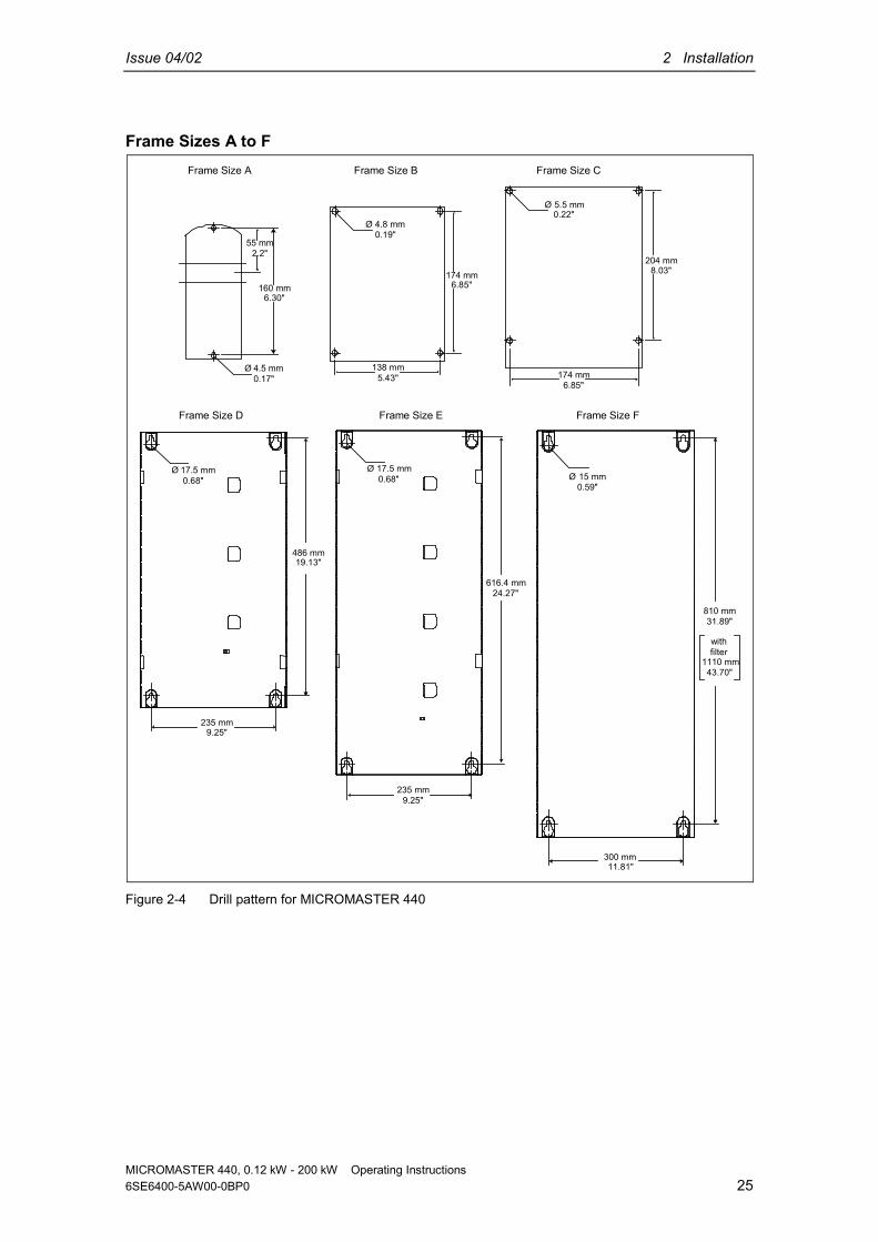
160 mm6.30"
55 mm2.2"
Ø 4.5 mm0.17"
Ø 4.8 mm0.19"
174 mm6.85"
138 mm5.43"
Ø 5.5 mm0.22"
204 mm8.03"
174 mm6.85"
Frame Size A
Frame Size D Frame Size E Frame Size F
Frame Size B Frame Size C
Ø 17.5 mm0.68"
486 mm19.13"
235 mm9.25"
616.4 mm24.27"
810 mm31.89"
withfilter
1110 mm43.70"
Ø 17.5 mm0.68" Ø 15 mm
0.59"
235 mm9.25"
300 mm11.81"
Figure 2-4 Drill pattern for MICROMASTER 440

2 Installation Issue 04/02
MICROMASTER 440, 0.12 kW - 200 kW Operating Instructions26 6SE6400-5AW00-0BP0
Frame Size FX
Figure 2-5 Installation dimensions for MICROMASTER 440 Frame size FX

Issue 04/02 2 Installation
MICROMASTER 440, 0.12 kW - 200 kW Operating Instructions6SE6400-5AW00-0BP0 27
Frame Size GX
4747

2 Installation Issue 04/02
MICROMASTER 440, 0.12 kW - 200 kW Operating Instructions28 6SE6400-5AW00-0BP0
Figure 2-6 Installation dimensions for MICROMASTER 440 Frame size GX
Table 2-1 Dimensions and Torques of MICROMASTER 440
Frame-Size Overall Dimensions Fixing Method Tightening Torquemm 73 x 173 x 149
AWidth xHeight xDepth inch 2,87 x 6,81 x 5,87
2 M4 Bolts4 M4 Nuts4 M4 Washers or fitting on a
standard rail
2,5 Nmwith washers fitted
mm 149 x 202 x 172B
Width xHeight xDepth inch 5,87 x 7,95 x 6,77
4 M4 Bolts4 M4 Nuts4 M4 Washers
2,5 Nmwith washers fitted
mm 185 x 245 x 195C
Width xHeight xDepth inch 7,28 x 9,65 x 7,68
4 M5 Bolts4 M5 Nuts4 M5 Washers
2,5 Nmwith washers fitted
mm 275 x 520 x 245D
Width xHeight xDepth inch 10,82 x 20,47 x 9,65
4 M8 Bolts4 M8 Nuts4 M8 Washers
3,0 Nmwith washers fitted
mm 275 x 650 x 245E
Width xHeight xDepth inch 10,82 x 25,59 x 9,65
4 M8 Bolts4 M8 Nuts4 M8 Washers
3,0 Nmwith washers fitted
mm 350 x 850 mm x 320height with filter 1150
FWidth xHeight xDepth inch 13,78 x 33,46 x 12,60
height with filter 45,28
4 M8 Bolts4 M8 Nuts4 M8 Washers
3,0 Nmwith washers fitted
mm 330 x 1555 x 360FX
Width xHeight xDepth inch 13,0 x 61,22 x 14,2
4 M8 Bolts4 M8 Nuts4 M8 Washers
13 Nm +30 %with washers fitted
mm 330 x 1875 x 560GX
Width xHeight xDepth inch 13,0 x 73,82 x 22,05
4 M8 Bolts4 M8 Nuts4 M8 Washers
13 Nm +30 %with washers fitted

Issue 04/02 2 Installation
MICROMASTER 440, 0.12 kW - 200 kW Operating Instructions6SE6400-5AW00-0BP0 29
2.3.1 Mounting on standard rail, Frame Size A
Fitting the Inverter to a 35 mm standard rail (EN 50022)1. Fit the inverter to the rail using the upper rail
latch.2. Push the
inverter againstthe rail and thelower rail latchshould clickinto place.
Removing the Inverter from the rail1. To disengaged the release mechanism of the
inverter, insert a screwdriver into the releasemechanism.
2. Apply a downward pressure and the lower rail latchwill disengage.
3. Pull the inverter from the rail.
Upperrail latch
Lowerrail latch
Release Mechanism

2 Installation Issue 04/02
MICROMASTER 440, 0.12 kW - 200 kW Operating Instructions30 6SE6400-5AW00-0BP0
2.3.2 Installation of options in the electronic boxThe front cover of the MICROMASTER 440 is designed so that the control module(normally the SDP) is almost flush with the opening in the front cover.If more than one option is to be installed in the electronic box, it is necessary toposition the entire electronic box further to the rear
Installation position 2Installation position1
Standard installation
Standard installation
Installation position1
Installation position 2
Figure 2-7 Options for the electronic box
Installing the options Remove the front cover:
• Unscrew two screws at the bottom side of the front cover.• Lift front cover up and out.
Remove retaining screws on the electronic box. Screw on electronic box in correct installation position as shown in Figure 2-7 Install additional options. Reinstall front cover.

Issue 04/02 2 Installation
MICROMASTER 440, 0.12 kW - 200 kW Operating Instructions6SE6400-5AW00-0BP0 31
2.4 Electrical installationWARNINGThe inverter must always be grounded.♦ To ensure the safe operation of the equipment, it must be installed and
commissioned by qualified personnel in full compliance with the warnings laiddown in these operating instructions.
♦ Take particular note of the general and regional installation and safetyregulations regarding work on dangerous voltage installations (e.g. EN50178), as well as the relevant regulations regarding the correct use of toolsand personal protective gear.
♦ Never use high voltage insulation test equipment on cables connected to theinverter.
♦ The mains input, DC and motor terminals, can carry dangerous voltages evenif the inverter is inoperative; wait 5 minutes to allow the unit to discharge afterswitching off before carrying out any installation work.
♦ If the front cover (Frame Sizes FX and GX) has been removed, the fanimpeller is exposed. There is danger of injury when the fan is running.
CAUTIONThe control, power supply and motor leads must be laid separately. Do not feedthem through the same cable conduit/trunking.

2 Installation Issue 04/02
MICROMASTER 440, 0.12 kW - 200 kW Operating Instructions32 6SE6400-5AW00-0BP0
2.4.1 General
WARNINGThe inverter must always be grounded. If the inverter is not grounded correctly,extremely dangerous conditions may arise within the inverter which could provepotentially fatal.
Operation with ungrounded (IT) suppliesThe use of filtered MICROMASTER 4 drives on unearthed mains supplies is notpermitted.On ungrounded supplies, it will be necessary to remove the ‘Y’ capacitor from theinside of the unit and fit an output choke. The procedure for removing this capacitoris described in Appendices D.The MICROMASTER will operate from ungrounded supplies and will continue tooperate if an input phase is shorted to ground. If an output phase is shorted toground, the MICROMASTER will trip and indicate F0001.
Operation with Residual Current Device (Frame Sizes A to F)If an RCD (also referred to as ELCB or RCCB) is fitted, the MICROMASTERinverters will operate without nuisance tripping, provided that: A type B RCD is used. The trip limit of the RCD is 300 mA. The neutral of the supply is grounded. Only one inverter is supplied from each RCD. The output cables are less than 50 m (screened) or 100 m (unscreened).
Operation with long cablesAll inverters will operate at full specification with cable lengths as follows:Frame Sizes A to F screened: 50 m unscreened: 150 mFrame Sizes FX and GX screened: 100 m unscreened: 300 mThe following cable lengths are possible using the output chokes specified incatalogue DA 51.2 : screened: 200 m unscreened: 150 m

Issue 04/02 2 Installation
MICROMASTER 440, 0.12 kW - 200 kW Operating Instructions6SE6400-5AW00-0BP0 33
2.4.2 Power and motor connections
WARNINGThe inverter must always be grounded.♦ Isolate the mains electrical supply before making or changing connections to
the unit.♦ Ensure that the inverter is configured for the correct supply voltage:
MICROMASTERS must not be connected to a higher voltage supply.♦ When synchronous motors are connected or when coupling several motors in
parallel, the inverter must be operated with voltage/frequency controlcharacteristic (P1300 = 0, 2 or 3).
CAUTIONAfter connecting the power and motor cables to the proper terminals, make surethat the covers have been replaced properly before supplying power to the unit!
NOTICE♦ Ensure that the appropriate circuit-breakers/fuses with the specified current
rating are connected between the power supply and inverter (see chapter 7,Tables starting on page 105).
♦ Use Class 1 60/75 oC copper wire only (for UL compliance). For tighteningtorque see Table 7-2 on page 103.
Access to the power and motor terminalsAccess to the power supply and motor terminals is possible by removing the covers(See Figure 2-8 and Figure 2-10).After removing the covers and exposing the terminals, complete power and motorconnections as shown in Figure 2-11.
Connection of braking unit (only for framesize FX and GX)A passage opening for access to the intermediate circuit connections has beenprovided on the top side of the inverter. It is possible to connect an external brakingunit to these terminals. The position is shown in Figure 2-9 and Figure 2-10.The maximum cross section of connections is 50 mm², but only provided thecrimped area of cable shoes on the equipment side is provided with a heat-shrinkable sleeve. This measure is important to ensure that air gaps and creepdistances are observed.

2 Installation Issue 04/02
MICROMASTER 440, 0.12 kW - 200 kW Operating Instructions34 6SE6400-5AW00-0BP0
L3
L2
L1
N
L
DC
DC+
B+
DC-
WU V
PE
R+
GroundGround
L3
L2
L3
L
NDCDC- DC+ VB- U W
PE
B+ R+
GroundGround
FRAME SIZE A
FRAME SIZE F
FRAME SIZE B & C
L1 UB-DCDC+L2 L3 DC- WV
NL B+ R+
PE
GroundGround
FRAME SIZE D & E
Ground Ground
DC- DC+ DC+B-
B+R+
PE
L1 UL2 L3 WV
NL
DC+
B+
Figure 2-8 MICROMASTER 440 Connection Terminals

Issue 04/02 2 Installation
MICROMASTER 440, 0.12 kW - 200 kW Operating Instructions6SE6400-5AW00-0BP0 35
Top adjustment rail
Phase W1/L3Phase V1/L2Phase U1/L1
Bottom adjustment rail
SDPStatus Display Panel
Fan
Shield connectioncontrol leads
Transformeradaption
Phase W2T3Phase V2/T2Phase U2/T1
Shield connectionMotor cable PE
Fan screws
Bottom retaining screw
Electronikbox
Top retaining screw
Fan fuses
Connection to the Y-capacitor
Connection C/L+, D/L-external braking unit
Cable opening for connection of anexternal braking unit
Shield connectionMains cable PE
Figure 2-9 MICROMASTER 440 connection drawing – frame size FX
2 Installation Issue 04/02
MICROMASTER 440, 0.12 kW - 200 kW Operating Instructions36 6SE6400-5AW00-0BP0
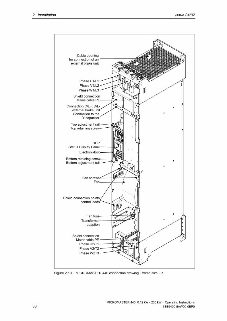
Phase W1/L3Phase V1/L2Phase U1/L1
SDPStatus Display Panel
Transformeradaption
Phase W2T3Phase V2/T2Phase U2/T1
Shield connectionMotor cable PE
Electronikbox
Fan fuse
Cable opening for connection of anexternal brake unit
Connection C/L+, D/L-external brake unitConnection to the
Y-capacitor
Top adjustment railTop retaining screw
Bottom retaining screwBottom adjustment rail
Fan screwsFan
Shield connection pointscontrol leads
Shield connectionMains cable PE
Figure 2-10 MICROMASTER 440 connection drawing - frame size GX

Issue 04/02 2 Installation
MICROMASTER 440, 0.12 kW - 200 kW Operating Instructions6SE6400-5AW00-0BP0 37
Frame Sizes A to F
L2L1N
FuseContactor
OptionalFilter
PE PE
Optionalline choke MICROMASTER 1)
PE
L/L1
N/L2
U
V
W
Motor
L3 Single Phase
PE
L3L2L1
FuseContactor
OptionalFilter
PE PE
Optionalline choke MICROMASTER 1)
PE
L3
L2
L1
U
V
W
Motor
Three Phase
PE
1) with and without filter
Frame Sizes FX and GX
L3L2L1
FuseContactor
OptionalFilter
PE PE
Optionalline choke MICROMASTER
PE
L3
L2
L1
U
V
W
Motor
3)
2)
2) without filter3) the commutation choke is to be earthed using the designated earthing point
Figure 2-11 Motor and Power Connections

2 Installation Issue 04/02
MICROMASTER 440, 0.12 kW - 200 kW Operating Instructions38 6SE6400-5AW00-0BP0
Adaptation of fan voltage (only for framesize FX and GX)A transformer is installed to adapt the existing line voltage to the fan voltage.It may be necessary to reconnect the transformer terminals on the primary side tocoincide with the existing line power.
380V 400V 440V 480V 380V 400V 440V 480V 380V 400V 440V 480V
Phase L1 Phase L2 Phase L3
Figure 2-12 Adaptation of fan voltage
CAUTIONIf the terminals are not reconnected to the actually present line voltage, the fanfuses can blow.
Replacement for fan fusesType Ferraz Gould Shawmut ATQR, 600 VFrame size Fuses (3 each)FX 2 AGX 2.5 A

Issue 04/02 2 Installation
MICROMASTER 440, 0.12 kW - 200 kW Operating Instructions6SE6400-5AW00-0BP0 39
2.4.3 Avoiding Electro-Magnetic Interference (EMI)The inverters are designed to operate in an industrial environment where a highlevel of EMI can be expected. Usually, good installation practices will ensure safeand trouble-free operation. If you encounter problems, follow the guidelines statedbelow.
Action to Take Ensure that all equipment in the cubicle is well grounded using short, thick
grounding cable connected to a common star point or busbar Make sure that any control equipment (such as a PLC) connected to the
inverter is connected to the same ground or star point as the inverter via ashort thick link.
Connect the return ground from the motors controlled by the inverters directlyto the ground connection (PE) on the associated inverter
Flat conductors are preferred as they have lower impedance at higherfrequencies
Terminate the ends of the cable neatly, ensuring that unscreened wires are asshort as possible
Separate the control cables from the power cables as much as possible, usingseparate trunking, if necessary at 90º to each other.
Whenever possible, use screened leads for the connections to the controlcircuitry
Ensure that the contactors in the cubicle are suppressed, either with R-Csuppressors for AC contactors or 'flywheel' diodes for DC contactors fitted tothe coils. Varistor suppressors are also effective. This is important when thecontactors are controlled from the inverter relay
Use screened or armored cables for the motor connections and ground thescreen at both ends using the cable clamps
WARNINGSafety regulations must not be compromised when installing inverters!
2.4.4 Screening Methods
Frame Sizes A, B and CFor frame sizes A, B and C the Gland Plate Kit is supplied as an option. It allowseasy and efficient connection of the necessary screening. See the Gland PlateInstallation Instructions contained on the Document CD-ROM, supplied with theMICROMASTER 440.

2 Installation Issue 04/02
MICROMASTER 440, 0.12 kW - 200 kW Operating Instructions40 6SE6400-5AW00-0BP0
Screening without a Gland PlateShould a Gland Plate not be available, then the inverter can be screened using themethodology shown in Figure 2-13.
L3
L2
L1
1
1
2
5
7
7
2
3
4
3
6
1 Mains power input2 Control cable3 Motor cable4 Footprint filter5 Metal back plate6 Use suitable clips to fix motor and control cable screens securely to metal back plate7 Screening cables
Figure 2-13 Wiring Guidelines to Minimize the Effects of EMI
Frame Sizes D, E and FThe Gland Plate is factory fitted. The installation of the screening is accomplishedusing the same methodology as in frame sizes A, B and C.
Frame Sizes FX and GXConnect the wire shields to the shield connection points shown in the connectiondrawing (see Figure 2-9 and Figure 2-10) .For this purpose twist the motor leads and screw all of them together to the shieldconnection point for the motor lead.
When using an EMI filter, a power commutating choke is required. The wire shieldsshould be fastened to the metallic mounting surface as close as possible to thecomponents.

Issue 04/02 3 Commissioning
MICROMASTER 440, 0.12 kW - 200 kW Operating Instructions6SE6400-5AW00-0BP0 41
3 Commissioning
This Chapter contains: A schematic diagram of the MICROMASTER 440 An overview of the commissioning options and the display and operator panels An overview of quick commissioing of the MICROMASTER 440
3.1 Block diagram.......................................................................................................... 43
3.2 Commission modes................................................................................................. 45
3.3 General operation.................................................................................................... 56

3 Commissioning Issue 04/02
MICROMASTER 440, 0.12 kW - 200 kW Operating Instructions42 6SE6400-5AW00-0BP0
WARNING♦ MICROMASTERS operate at high voltages.♦ When operating electrical devices, it is impossible to avoid applying
hazardous voltages to certain parts of the equipment.♦ Emergency Stop facilities according to EN 60204 IEC 204 (VDE 0113) must
remain operative in all operating modes of the control equipment. Anydisengagement of the Emergency Stop facility must not lead to uncontrolledor undefined restart.
♦ Wherever faults occurring in the control equipment can lead to substantialmaterial damage or even grievous bodily injury (i.e. potentially dangerousfaults), additional external precautions must be taken or facilities provided toensure or enforce safe operation, even when a fault occurs (e.g. independentlimit switches, mechanical interlocks, etc.).
♦ Certain parameter settings may cause the inverter to restart automaticallyafter an input power failure.
♦ Motor parameters must be accurately configured for motor overloadprotection to operate correctly.
♦ This equipment is capable of providing internal motor overload protection inaccordance with UL508C section 42. Refer to P0610 and P0335, i2t is ON bydefault. Motor overload protection can also be provided using an externalPTC (disabled by default P0601).
♦ This equipment is suitable for use in a circuit capable of delivering not morethan 10,000 symmetrical amperes (rms), for a maximum voltage of 230 V /460 V / 575 V when protected by a H or K type fuse (see Tables starting onpage 105).
♦ This equipment must not be used as an ‘emergency stop mechanism’ (seeEN 60204, 9.2.5.4)
CAUTIONOnly qualified personnel may enter settings in the control panels. Particularattention must be paid to safety precautions and warnings at all times.

Issue 04/02 3 Commissioning
MICROMASTER 440, 0.12 kW - 200 kW Operating Instructions6SE6400-5AW00-0BP0 43
3.1 Block diagramPE
1 - 3 AC 200 - 240 V3 AC 380 - 480 V3 AC 500 - 600 V
SI
PE L/L1, N/L2orL/L1, N/L2,L3orL1, L2, L3
=3 ~
PE U,V,W
M
1 2
DIP Switches(on I/O Board)
AIN1AIN2
0 - 10 Vvoltage
0 - 20 mAcurrent
1 2DIP Switches
(on Control Board)
60 Hz
50 Hz
Notused
Jog0
I
P
Fn
Hz
150.00
A/D
A/D
+10 V
0 V
MotorPTC
0 - 20 mAmax. 500 Ω
RELAIS 1
RELAIS 2
4.7 kΩ min
NPN
PNPor
Opto-Isolierung
CPU
RELAIS 3
RS485
D/A
D/A
BOP
BOPserial
protocol
externalbraking m
oduleconnection
D/L-
C/L+
Frame SizesA to F
B+/DC+
DC/R+
Factoryfittedlink
B-
R
DC-
~
=
Frame SizesFX and GX
30 V DC / 5 A (resistive)250 V AC / 2 A (inductive)
AIN1+
AIN1-
AIN2+
AIN2-
DIN1
DIN2
DIN3
DIN4
DIN5
DIN6
PTCA
PTCB
AOUT 1+
AOUT 1-
AOUT 2+
AOUT 2-
P+
N-
COM
NC
NO
COM
NC
NO
COM
NO
Isolated +24 V(Output)
Isolated 0 V(Output)
1
2
3
4
10
11
5
6
7
8
16
17
9
28
14
15
12
13
26
27
29
30
20
18
19
25
23
24
22
21
0 - 20 mAmax. 500 Ω
Figure 3-1 Inverter block diagram

3 Commissioning Issue 04/02
MICROMASTER 440, 0.12 kW - 200 kW Operating Instructions44 6SE6400-5AW00-0BP0
3.1.1 Standard settings for the terminalsSee Figure 3-2.
3.1.2 Analogue inputsAnalogue input 1 (AIN1) can be used with: 0 - 10 V, 0 - 20 mA and -10 V to +10 VAnalogue input 2 (AIN2) can be used with: 0 - 10 V and 0 - 20 mA
The analog input circuit can be alternatively configured to provide additional digitalinputs (DIN7 & DIN8) as shown:
1
2
10
11DIN8
1
2
3
4DIN7
Figure 3-2 Configuration of the analogue input as a digital input
When an analogue input is configured as a digital input the threshold values are asfollows:
1.75 V DC = OFF3.70 V DC = ON
Terminal 9 (24 V) can also be used to drive the analog inputs when used as digitalinputs. Terminals 2 and 28 (0 V) must be linked together.

Issue 04/02 3 Commissioning
MICROMASTER 440, 0.12 kW - 200 kW Operating Instructions6SE6400-5AW00-0BP0 45
3.2 Commission modesIn the standard version, the MICROMASTER 440 is fitted with the Status DisplayPanel (SDP) (see Figure 3-3) with which it is possible to use the inverter with thepre-assigned factory settings for a large range of applications. If these factorysettings are not suitable, you can adapt them to suit your equipment conditionsusing the Basic Operator Panel (BOP) (see Figure 3-3) or the Advanced OperatorPanel (AOP) (see Figure 3-3). The BOP and AOP are available as options. Youcan also adjust the factory settings using the PC IBN tool "Drive Monitor" or"STARTER“. This software is available on the CD ROM which comes with thedocumentation of the unit.
jog0
1
P
Fn
Hz
RUNNINGP000I = 4.8
fnf lpv
F= 50.0 HZ
RPM=1500V=400v
jog0
1
P
Fn
menu
Hz
150.00
SDP BOP AOPStatus Display Panel Basic Operator Panel Advanced Operator Panel
Figure 3-3 Panels available for the MICROMASTER 440 Inverter
NOTICEThe factory frequency setting can be changed with the DIP switches below theSDP. The inverter is delivered as follows: DIP switch 2:
♦ Off position: Europeandefaults (50 Hz, kW etc.)
♦ On position: North Americandefaults (60 Hz, hp etc.)
DIP switch 1:Not for customer use.
Frequency SettingDIP Switch
Figure 3-4 DIP switch
3 Commissioning Issue 04/02
MICROMASTER 440, 0.12 kW - 200 kW Operating Instructions46 6SE6400-5AW00-0BP0
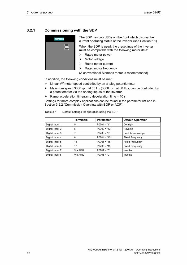
3.2.1 Commissioning with the SDP
In addition, the following conditions must be met: Linear V/f motor speed controlled by an analog potentiometer. Maximum speed 3000 rpm at 50 Hz (3600 rpm at 60 Hz); can be controlled by
a potentiometer via the analog inputs of the inverter. Ramp acceleration time/ramp deceleration time = 10 sSettings for more complex applications can be found in the parameter list and inSection 3.2.2 "Commission Overview with BOP or AOP".
Table 3-1 Default settings for operation using the SDP
Terminals Parameter Default OperationDigital Input 1 5 P0701 = ‘1’ ON rightDigital Input 2 6 P0702 = ‘12’ ReverseDigital Input 3 7 P0703 = ‘9’ Fault Acknowledge Digital Input 4 8 P0704 = ‘15’ Fixed Frequency
Digital Input 5 16 P0705 = ‘15’ Fixed FrequencyDigital Input 6 17 P0706 = ‘15’ Fixed FrequencyDigital Input 7 Via AIN1 P0707 = ‘0’ InactiveDigital Input 8 Via AIN2 P0708 = ‘0’ Inactive
The SDP has two LEDs on the front which display thecurrent operating status of the inverter (see Section 6.1).
When the SDP is used, the presettings of the invertermust be compatible with the following motor data: Rated motor power Motor voltage Rated motor current Rated motor frequency(A conventional Siemens motor is recommended)

Issue 04/02 3 Commissioning
MICROMASTER 440, 0.12 kW - 200 kW Operating Instructions6SE6400-5AW00-0BP0 47
Basic operation with SDPWith the SDP fitted, the following is possible:
Start and stopping the motor (DIN1 via external switch) Reversing the motor (DIN2 via external switch) Fault Reset (DIN3 via external switch)
Controlling the speed of the motor is accomplished by connecting the analog inputsas shown in the Figure 3-5.
Analogueoutput0 - 20 mA(500 Ω)
AIN1OFF = Voltage 0 - 10 V
ON = Current 0 - 20 mA
AIN2OFF = Voltage 0 - 10 V
ON = Current 0 - 20 mA
N-
P+
ACK
Figure 3-5 Basic operation with SDP
3 Commissioning Issue 04/02
MICROMASTER 440, 0.12 kW - 200 kW Operating Instructions48 6SE6400-5AW00-0BP0
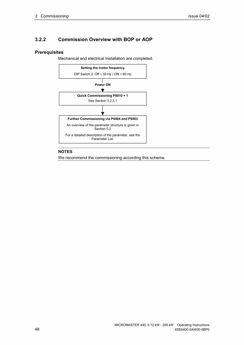
3.2.2 Commission Overview with BOP or AOP
PrerequisitesMechanical and electrical Installation are completed.
NOTESWe recommend the commissioning according this scheme.
Setting the motor frequency
DIP Switch 2: Off = 50 Hz / ON = 60 Hz
Quick Commissioning P0010 = 1See Section 3.2.3.1
Further Commissioning via P0004 and P0003
An overview of the parameter structure is given inSection 5.3
For a detailed description of the parameter, see theParameter List.
Power ON

Issue 04/02 3 Commissioning
MICROMASTER 440, 0.12 kW - 200 kW Operating Instructions6SE6400-5AW00-0BP0 49
3.2.2.1 Commissioning with the BOP
You can alter parameter values via the BOP. To setparameters on this panel, you must remove the SDP andattach the BOP (see Appendix A).
The BOP features a five-digit, seven-segment display forshowing parameter numbers and values, alarm and faultmessages and setpoints and actual values. Parametersets cannot be saved via the BOP.
Table 3-2 shows the factory default settings for operationvia the BOP.
NOTICE♦ The BOP motor control functions are disabled by default. To control the motor
via the BOP, parameter P0700 should be set to 1 and P1000 set to 1.♦ The BOP can be fitted to and removed from the inverter whilst power is
applied.♦ If the BOP has been set as the I/O control (P0700 = 1), the drive will stop if
the BOP is removed.
Table 3-2 Default settings for operation using the BOP
Parameter Meaning Default Europe (North America)P0100 Operating Mode Europe/US 50 Hz, kW (60Hz, hp)P0307 Power (rated motor) Dimension (kW (Hp)) depending on setting of P0100.
[Value depending on variant.]P0310 Motor frequency rating 50 Hz (60 Hz)P0311 Motor speed rating 1395 (1680) rpm [depending on variant]P1082 Maximum Motor Frequency 50 Hz (60 Hz)

3 Commissioning Issue 04/02
MICROMASTER 440, 0.12 kW - 200 kW Operating Instructions50 6SE6400-5AW00-0BP0
Buttons on the BOPPanel/Button Function Effects
IndicatesStatus The LCD displays the settings currently used by the inverter.
Start motor Pressing the button starts the inverter. This button is disabled bydefault. To enable this button set P0700 = 1.
Stop motor
OFF1 Pressing the button causes the motor to come to a standstillat the selected ramp down rate. Disabled by default; toenable set P0700 = 1.
OFF2 Pressing the button twice (or once long) causes the motor tocoast to a standstill. This function is always enabled.
Changedirection
Press this button to change the direction of rotation of the motor.Reverse is indicated by a minus (-) sign or a flashing decimal point.Disabled by default, to enable set P0700 = 1.
Jog motor
Pressing this button while the inverter has no output causes themotor to start and run at the preset jog frequency. The motor stopswhen the button is released. Pressing this button when the motor isrunning has no effect.
Functions
This button can be used to view additional information.Pressing and holding the button for 2 seconds from any parameterduring operation, shows the following:1. DC link voltage (indicated by d – units V).2. Output current. (A)3. Output frequency (Hz)4. Output voltage (indicated by o – units V).5. The value selected in P0005 (If P0005 is set to show any of the
above (3, 4, or 5) then this will not be shown again).Additional presses will toggle around the above displays.Jump FunctionFrom any parameter (rXXXX or PXXXX) a short press of the Fnbutton will immediately jump to r0000, you can then change anotherparameter, if required. Upon returning to r0000, pressing the Fnbutton will return you to your starting point.QuitIn case of a fault or alarm the button resets the fault or alarmmessage on the operator panel display.
Accessparameters Pressing this button allows access to the parameters.
Increasevalue Pressing this button increases the displayed value.
Decreasevalue Pressing this button decreases the displayed value.
Figure 3-6 Buttons on the BOP

Issue 04/02 3 Commissioning
MICROMASTER 440, 0.12 kW - 200 kW Operating Instructions6SE6400-5AW00-0BP0 51
Changing parameters with the BOPThe procedure for changing the value of parameter P0004 is described below.Modifying the value of an indexed parameter is illustrated using the example ofP0719. Follow exactly the same procedure to alter other parameters that you wishto set via the BOP.
Changing P0004 – parameter filter function
Step Result on display
1 Press to access parameters
2 Press until P0004 is displayed
3 Press to access the parameter value level
4 Press or to the required value
5 Press to confirm and store the value
6 Only the command parameters are visible to theuser.
Changing P0719 an indexed parameterSelection of command/setpoint source
Step Result on display
1 Press to access parameters
2 Press until P0719 is displayed
3 Press to access the parameter value level
4 Press to display current set value
5 Press or to the required value
6 Press to confirm and store the value
7 Press until r0000 is displayed
8 Press to return the display to the standarddrive display (as defined by the customer)
Figure 3-7 Changing parameters via the BOP
NOTESIn some cases - when changing parameter values - the display on the BOP shows
. This means the inverter is busy with tasks of higher priority.

3 Commissioning Issue 04/02
MICROMASTER 440, 0.12 kW - 200 kW Operating Instructions52 6SE6400-5AW00-0BP0
Changing single digits in Parameter valuesFor changing the parameter value rapidly, the single digits of the display can bechanged by performing the following actions:Ensure you are in the parameter value changing level (see "Changing parameterswith BOP").
1. Press (function button), which causes the right hand digit to blink.
2. Change the value of this digit by pressing / .
3. Press (function button) again causes the next digit to blink.4. Perform steps 2 to 4 until the required value is displayed.
5. Press the to leave the parameter value changing level.
NOTESThe function button may also be used to acknowledge a fault condition
3.2.2.2 Commissioning with the AOP
The AOP is available as an option. Its advanced featuresinclude the following: Multilingual clear text display Upload/download of multiple parameter sets Programmable via PC Multidrop capability to drive up to 30 invertersPlease refer to the AOP Manual for details or contact yourlocal Siemens sales office for assistance.
3.2.3 Commissioning functions with BOP / AOP
3.2.3.1 Quick commissioning (P0010=1)
Mechanical and electrical installation of the inverter must be completed beforerunning „Quick Commissioning“.It is important that parameter P0010 is used for commissioning and P0003 is usedto select the access level.There are three user levels, standard, extended and expert. The lower the accesslevel fewer parameters can be seen while performing Quick commissioning. Thevalues for these parameters are either the default settings or are calculated duringquick commissioning.Quick commissioning includes motor and ramp setting parameters.Quick Commissioning concludes with P3900, which, when set to 1, will perform thenecessary motor calculations and clear all other parameters (not included inP0010 = 1) to the default settings. After completing Quick Commissioning withP3900 = 1, the inverter is then ready to run; this will only happen in the QuickCommissioning mode.

Issue 04/02 3 Commissioning
MICROMASTER 440, 0.12 kW - 200 kW Operating Instructions6SE6400-5AW00-0BP0 53
Flow chart Quick Commissioning (QC)
P0010 Start Quick Commissioning 2)
0 Ready to Run1 Ready to Run30 Factory Setting
P0100 Operation for Europe/N. America0 Power in kW; f default 50 Hz1 Power in hp; f default 60 Hz2 Power in kW; f default 60 Hz
NOTESettings 0 and 1 should be changed using the DIPswitches to allow permanent setting. The DIPswitches should be used to create permanentsettings. After a mains break the DIP switch settingsoveride the parameter settings.
P0205 Inverter application0 Constant torque1 Variable torque
NoteP0205 = 1 should only be used in applications withquadratic characteristic (pumps, fans)
P0300 Select motor type1 Asynchronous rotational motor2 Synchronous rotational motor
NoteWith P0300 = 2 the control parameters are disabled
P0304 Rated Motor Voltage 1)
Setting range: 10 V - 2000 VNominal motor voltage (V) from rating plate.
P0307 Rated Motor Power 1)
Setting range: 0.01 kW - 2000 kWNominal motor power (kW) from rating plate.If P0100 = 1, values will be in hp.
P0308 Rated motor cosPhi 1)
Setting range: 0.000 - 1.000Nom. motor power factor (cosPhi) from rating plate .Visible only when P0100 = 0, 2, (motor power in kW).
P0309 Rated motor efficiency 1)
Setting range: 0.0 - 99.9 %Nominal motor efficiency in % from rating plate. .Visible only when P0100 = 1, ( motor power in hp).
P0310 Rated Motor Frequency 1)
Setting range: 12 Hz - 650 HzNominal motor frequency (Hz) from rating plate.
P0311 Rated Motor Speed 1)
Setting range: 0 - 40.000 U/minNominal motor speed (rpm) from rating plate.
P0320 Motor magnetizing currentSetting range: 0.0 - 99.0 %Motor magnetizing current (%) relative to the ratedmotor current (P0305).
P0335 Motor cooling0 Self-cooled1 Force-cooled2 Self-cooled and internal fan3 Force-cooled and internal fan
P0640 Motor overload factorSetting range: 10.0 - 400.0 %Motor overload current limit [%] relative to P0305(rated motor current).
1
Access level
1
3
2
1
2
P0305 Rated Motor Current 1)
Setting range: 0 - 2 x inverter rated current (A)Nominal motor current (A) from rating plate.
1
2
3
1
1
2
2
1
P0700 Selection of Command Source 2)
0 Factory Setting1 BOP / AOP2 Terminals (Digital Inputs)
1
NoteIf P0700 = 2 is selected, the function of the digitalinputs can be determind via P0701 to P0708. P0701to P0708 = 99 enables the BICO-parameterization forthe digital inputs.
P0003 User access level 2)
1 Standard2 Extended3 Expert
1
1) Motor-specific parameters – see motor rating plate.2) The parameters offer more setting options than listed here. See Parameter List for further setting options.

3 Commissioning Issue 04/02
MICROMASTER 440, 0.12 kW - 200 kW Operating Instructions54 6SE6400-5AW00-0BP0
P1000 Selection of Frequency Setpoint 2)
1 Motor potentiometer setpoint2 Analog setpoint 13 Fixed frequency setpoint7 Analog setpoint 2
P1080 Min. Motor FrequencySetting range: 0 - 650 HzSets minimum motor frequency (0 - 650 Hz) at whichthe motor will run irrespective of the frequency set-point. The value is valid for both motor directions.
P1082 Max. Motor FrequencySetting range: 0 - 650 HzSets maximum motor frequency (0 - 650 Hz) at whichthe motor will run irrespective of the frequency set-point. The value is valid for both motor directions.
P1120 Ramp-Up TimeSetting range: 0 - 650 sTime taken for the motor to accelerate from standstillup to maximum motor frequency.
P1121 Ramp-Down TimeSetting range: 0 - 650 sTime taken for motor to decelerate from maximummotor frequency down to standstill.
P1135 OFF3 ramp-down timeSetting range: 0 - 650 sDefines the ramp down time from the maximumfrequency to standstill for the OFF3 command.
P1300 Control mode0 V/f with linear charac.1 V/f with FCC2 V/f with parabolic charac.3 V/f with programmable charac.5 V/f for textile applications6 V/f with FCC for textile applications19 V/f control with independent voltage setpoint20 Sensorless vector control21 Vector control with sensor22 Sensorless vector torque-control23 Vector torque-control with sensor
1
1
1
1
1
2
2
NoteFor setting a additional setpoint see Parameter List.If P1000 = 1 or 3 the selection depends on thesettings of P0700 to P0708.
NoteVector control modes can only be used together withan asynchronous motor
P1500 Selection of torque setpoint 2)
0 No main setpoint2 Analog setpoint4 USS on BOP link5 USS on COM link6 CB on COM link7 Analog setpoint 2
P1910 Select motor data identification 2)
0 Disabled1 Identification of all parameters with
parameter change.2 Identification of all parameters without
parameter change.3 Identification of saturation curve with
parameter change.4 Identification of saturation curve without
parameter change.
P3900 End Quick Commissioning0 End Quick Commissioning without
motor calculation or factory reset.1 End Quick Commissioning with motor
calculation and factory reset.2 End Quick Commissioning with motor
calculation and with I/O reset.3 End Quick Commissioning with motor
calculation but without I/O reset.
1
2
2
NoteFor setting a additional setpoint see Parameter List.
NoteMotor identification must be performed with a coldmotor (20 °C). If the ambient temperature is notwithin the range of 20°C (+5°C), P0625 Ambientmotor temperature must be updated.
Quick Commissioning complete, the inverter goesinto ready-to-run state
Alarm A0541Motor data idendification active.
P1910 = 1,2,3,4P1910 = 0
P3900 = 1,2 P3900 = 3
Switch on Motor, Motor data identificationstarts. After completing motor identifi-cation, Alarm message A0541 disappears.If the motor shall be operated with fieldweakening, the operation is to repeat withP1910 = 3 "saturation curve".
2) The parameters offer more setting options than listed here. See Parameter List for further setting options.

Issue 04/02 3 Commissioning
MICROMASTER 440, 0.12 kW - 200 kW Operating Instructions6SE6400-5AW00-0BP0 55
Motor data for parameterization
SIEMENS3 ~Mot. 1PQ6 317-4AA60-Z 315L UC 0108/023730002 IM B3
V
400690
380...420 V , 360...330 A; 660...725 V , 205...192 A, 50 Hz
Hz
50
A
345200
kW
200
cosϕϕϕϕ
0,87
1/min
1488
IA/IN TE s Certif. No IP
54
EN 60 034 nmax 2600 1/min Gew./Wt. 1,20 t
P0305
P0311P0307P0310
P0308P0304
Figure 3-8 Typical Motor Rating Plate Example
NOTICE P0308 is only visible if P0003 ≥ 2. Depending on the settings for parameter
P0100, only P 0308 or P0309 is displayed. P0307 indicates kW or HP depending upon the setting of P0100. For detailed
information, please see the Parameter List. Changing motor parameters is only possible with P0010 = 1 (factory setting)
and P0004 = 0 or 3. Ensure that the inverter is configured correctly to the motor.
3.2.4 Reset to Factory defaultTo reset all parameters to the factory default settings; the following parametersshould be set as follows (BOP, AOP or Communication Option needed):1. Set P0010 = 302. Set P0970 = 1
NOTEThe reset process can take up to 3 minutes to complete.

3 Commissioning Issue 04/02
MICROMASTER 440, 0.12 kW - 200 kW Operating Instructions56 6SE6400-5AW00-0BP0
3.3 General operationFor a full description of standard and extended parameters, please refer to theParameter List.
NOTICE1. The inverter does not have a main power switch and is live when the mains
supply is connected. It waits, with the output disabled, until the RUN button ispressed or for the presence of a digital ON signal at terminal 5 (rotate right).
2. If a BOP or an AOP is fitted and the output frequency is selected to bedisplayed (P0005 = 21) the corresponding setpoint is displayed approximatelyevery 1.0 seconds while the inverter is stopped.
3. The inverter is programmed at the factory for standard applications onSiemens four-pole standard motors that have the same power rating as theinverters. When using other motors it is necessary to enter the specificationsfrom the motor's rating plate. See Figure 3-8 for details on how to read motordata.
4. Changing motor parameters is not possible unless P0010 = 1.5. You must set P0010 back to 0 in order to initiate a run.
Basic operation with the BOP/AOPPrerequisites P0010 = 0 (in order to initiate the run command correctly). P0700 = 1 (enables the start/stop button on the BOP). P1000 = 1 (this enables the motor potentiometer setpoints).
1. Press the green Button to start the motor.2. Press the Button while the motor is turning. Motor speed increases to
50 Hz.3. When the inverter reaches 50 Hz, press the Button . Motor speed and
display is decreased.4. Change the direction of rotation with the Button .5. The red button stops the motor .

Issue 04/02 3 Commissioning
MICROMASTER 440, 0.12 kW - 200 kW Operating Instructions6SE6400-5AW00-0BP0 57
External motor thermal overload protectionWhen operated below rated speed, the cooling effect of fans fitted to the motorshaft is reduced. Consequentially, most motors require de-rating for continuousoperation at low frequencies. To ensure that the motors are protected againstoverheating under these conditions, a PTC temperature sensor must be fitted tothe motor and connected to the inverter control terminals.
PTC/KTY
5 V
Kl. 14
Kl. 15
A
D
574 Ω
PTC-Auslöseschwelle = 4 V PTC-Charakteristik für 1LG/1LA-Motoren KTY84-Charakteristik
Figure 3-9
With PTC sensor (P0601 = 1)If the PTC in the motor is connected to the MICROMASTER 440 control terminals14 (PTCA) and 15 (PTCB) and the PTC function enabled by setting P0601 = 1,then the MICROMASTER 440 will operate as normal providing the resistance atthe terminals remains below approximately 1500 Ω. If this value is exceeded, theinverter indicates a warning A0511 and then a fault F0011. The actual resistancevalue at which this occurs will not be less than 1000 Ω, and not more than 2000 Ω.
With KTY84 sensor (P0601 = 2)The KTY84 has to be connected so that the diode is forward biased; that is theanode is connected to terminal 14 (PTCA) and the cathode to terminal 15 (PTCB).If the temperature monitoring function is enabled by setting P0601 = 2, thetemperature of the sensor (and therefore the motor windings) is written toparameter r0035. The threshold motor temperature can now be set usingparameter P0604 (default setting 130 °C).
Connection failureIf the connection to the PTC or KTY84 sensor becomes open circuit or short circuit,a fault will be indicated, and by default the drive will trip.
NOTETo enable the trip function, set parameter P0701, P0702 or P0703 = 29.


Issue 04/02 4 Using the MICROMASTER 440
MICROMASTER 440, 0.12 kW - 200 kW Operating Instructions6SE6400-5AW00-0BP0 59
4 Using the MICROMASTER 440
This Chapter contains: An explanation of the various methods of controlling the inverter A summary of the types of control of the inverter
4.1 Frequency setpoint (P1000).................................................................................... 60
4.2 Command sources (P0700) .................................................................................... 61
4.3 OFF and braking functions...................................................................................... 61
4.4 Control modes (P1300) ........................................................................................... 63
4.5 Extended Functions for the MICROMASTER 440 .................................................. 64
4.6 Faults and warnings ................................................................................................ 64

4 Using the MICROMASTER 440 Issue 04/02
MICROMASTER 440, 0.12 kW - 200 kW Operating Instructions60 6SE6400-5AW00-0BP0
WARNING♦ When operating electrical devices, it is impossible to avoid applying
hazardous voltages to certain parts of the equipment.♦ Emergency Stop facilities according to EN 60204 IEC 204 (VDE 0113) must
remain operative in all operating modes of the control equipment. Anydisengagement of the Emergency Stop facility must not lead to uncontrolledor undefined restart.
♦ Wherever faults occurring in the control equipment can lead to substantialmaterial damage or even grievous bodily injury (i.e. potentially dangerousfaults), additional external precautions must be taken or facilities provided toensure or enforce safe operation, even when a fault occurs (e.g. independentlimit switches, mechanical interlocks, etc.).
♦ MICROMASTERS operate at high voltages.♦ Certain parameter settings may cause the inverter to restart automatically
after an input power failure.♦ Motor parameters must be accurately configured for motor overload
protection to operate correctly.♦ This equipment is capable of providing internal motor overload protection in
accordance with UL508C section 42. Refer to P0610 and P0335, i2t is ON bydefault. Motor overload protection can also be provided using an externalPTC (disabled by default P0601).
♦ This equipment is suitable for use in a circuit capable of delivering not morethan 10,000 symmetrical amperes (rms), for a maximum voltage of 230 V /460 V / 575 V when protected by a H or K type fuse (see Tables starting onpage 105)
♦ This equipment must not be used as an ‘emergency stop mechanism’ (seeEN 60204, 9.2.5.4)
4.1 Frequency setpoint (P1000) Default: Terminal 3/4 (AIN+/ AIN-, 0…10 V
corresponds to 0…50/60 Hz) Other settings: see P1000
NOTESFor USS see Reference Manual, for PROFIBUS see Reference Manual andPROFIBUS Instructions.
Issue 04/02 4 Using the MICROMASTER 440
MICROMASTER 440, 0.12 kW - 200 kW Operating Instructions6SE6400-5AW00-0BP0 61
4.2 Command sources (P0700)NOTICEThe ramp times and ramp-smoothing functions also affect how the motor starts andstops. For details of these functions, please refer to parameters P1120, P1121,P1130 – P1134 in the Parameter List.
Starting the motor Default: Terminal 5 (DIN 1, high) Other settings: see P0700 to P0708
Stopping the motorThere are several ways to stop the motor: Default:
♦ OFF1 (4.3.1) Terminal 5 (DIN 1, low)♦ OFF2 (4.3.2) Off button on BOP/AOP, pressing the Off button once long
(two seconds) or twice (with default settings not possiblewithout BOP/AOP)
♦ OFF3 (4.3.3) Not active in the default (factory) setting Other settings: see P0700 to P0708
Reversing the motor Default: Terminal 6 (DIN 2, high) Other settings: see P0700 to P0708
4.3 OFF and braking functions
4.3.1 OFF1This command (produced by canceling the ON command) causes the inverter tocome to a standstill at the selected ramp-down rate.
Parameter to change ramp-down time see P1121
NOTICE ON and the following OFF1 command must have the same source. If the ON/OFF1 command is set to more than one digital input, only the last set
digital input is valid e.g. DIN3 is active. OFF1 can be combined with DC braking or Compound braking.

4 Using the MICROMASTER 440 Issue 04/02
MICROMASTER 440, 0.12 kW - 200 kW Operating Instructions62 6SE6400-5AW00-0BP0
4.3.2 OFF2This command causes the motor to coast to a standstill (pulses disabled).
NOTICEThe OFF2 command can have one or more sources. By default the OFF2command is set to BOP/AOP. This source still exists even if other sources aredefined by one of the following parameters, P0700 to P0708 inclusive.
4.3.3 OFF3An OFF3 command causes the motor to decelerate rapidly.For starting the motor when OFF3 is set, the binary input has to be closed (high). IfOFF3 is high, the motor can be started and stopped by OFF1 or OFF2.If OFF3 is low the motor cannot be started. Ramp down time: see P1135
NOTICEOFF3 can be combined with DC braking or Compound braking.
4.3.4 DC brakingDC braking is possible together with OFF1 and OFF3. A DC current is applied tostop the motor quickly and hold the shaft stationary until the end of the brakingperiod. Enable DC braking: see P0701 to P0708 Set DC braking period: see P1233 Set DC braking current: see P1232 Set DC braking start frequency: see P1234
NOTICEIf no digital input is set to DC braking and P1233 ≠ 0, DC braking will be active afterevery OFF1 command with the time set in P1233.
4.3.5 Compound BrakingCompound Braking is possible with both OFF1 and OFF3. For Compound Brakinga DC component is added to the AC current.Set the braking current: see P1236
4.3.6 Dynamic brakingBraking with an external resistor (Frame Size A to F using the intrated chopper,framesize FX and FX using and external braking chopper) is a method of brakingthat allows a smoothed, controlled reduction in motor speed in a linear manner.

Issue 04/02 4 Using the MICROMASTER 440
MICROMASTER 440, 0.12 kW - 200 kW Operating Instructions6SE6400-5AW00-0BP0 63
4.4 Control modes (P1300)The various modes of operation of the MICROMASTER 440 control the relation-ship between the speed of the motor and the voltage supplied by the inverter. Asummary of the control modes available are listed below:
Linear V/f control, P1300 = 0Can be used for variable and constant torque applications, such as conveyorsand positive displacement pumps.
Linear V/f control with FCC (Flux Current Control), P1300 = 1This control mode can be used to improve the efficiency and dynamicresponse of the motor.
Parabolic V/f control P1300 = 2This mode can be used for variable torque loads, such as fans and pumps.
Multi-point V/f control P1300 = 3For information regarding this mode of operation, please consult the MM440Reference Manual.
V/f control for textile applications P1300 = 5There is no slip compensation or resonance damping. The Imax controllerrefers to the voltage instead of frequency.
V/f control with FCC for textile applications P1300 = 6 A combination of P1300 = 1 and P1300 = 5.
V/f control with independent voltage setpoint P1300 = 19The voltage setpoint can be given using P1330 independent from the RampFunction Generator (RFG) output frequency
Sensorless Vector Control P1300 = 20This feature allows the speed of the motor to be controlled with inherent slipcompensation. It allows for high torque, improved transient response, excellentspeed holding and improved torque at low frequencies. Allows change fromvector control to torque control (see P1501).
Speed control with Encoder Feedback P1300 = 21The field orientation control with speed encoder feedback enables :♦ increased accuracy and improved dynamic response of speed control♦ mproved control characteristics at low speeds
Sensoless Vector Torque Control P1300 = 22This feature allows the inverter to control the torque of a motor. In anapplication where a constant torque is required, a torque setpoint can beestablished and the inverter will vary the current delivered to the motor tomaintain the required torque.
Torque control with Encoder Feedback P1300 = 23Torque control with encoder feedback enables an increased accuracy andimproved dynamic response of torque control.

4 Using the MICROMASTER 440 Issue 04/02
MICROMASTER 440, 0.12 kW - 200 kW Operating Instructions64 6SE6400-5AW00-0BP0
4.5 Extended Functions for the MICROMASTER 440
Free Function Blocks (P2800 ff)Using free function blocks, internal signals (Digital inputs, set points, actualvalues, ...) can be interlinked, to enable application specific control.
Kinetic Buffering (P2800 ff)Kinetic Buffering provides ride through of power supply faults or interruptions, foras long as the kinetic energy can allow. It also allows for the controlled stop of thedrive following a power supply fault.
Positioning Ramp down (P0500 ff)The positioning ramp down enables the controlled ramp down to a stoppingposition , for example triggered by an end-switch.
4.6 Faults and warnings
SDPIf an SDP is fitted, the fault states and warnings are indicated by the two LEDs onthe panel, see section 6.1 on page 90 for further information.Fault-free operation of the inverter is indicated by the following sequence of LEDdisplays: Green and yellow = Ready to run Green = Run
BOPIf a BOP is fitted and a fault occurs, it will be shown on the display. It is possible toview the last 8 fault codes in P0947 and the last 4 warnings in P2110. For furtherinformation, please refer to the Parameter List.
AOPIf the AOP is fitted, the fault and warning codes are displayed on the LCD panel.

Issue 04/02 5 System parameters
MICROMASTER 440, 0.12 kW - 200 kW Operating Instructions6SE6400-5AW00-0BP0 65
5 System parameters
This Chapter contains: An overview of the parameter structure of the MICROMASTER 440 A parameter list in short form
5.1 Introduction to MICROMASTER system parameters.............................................. 66
5.2 Parameter overview ................................................................................................ 67
5.3 Parameter list (short form) ...................................................................................... 68
5.4 Command and Drive Datasets - Overview.............................................................. 84
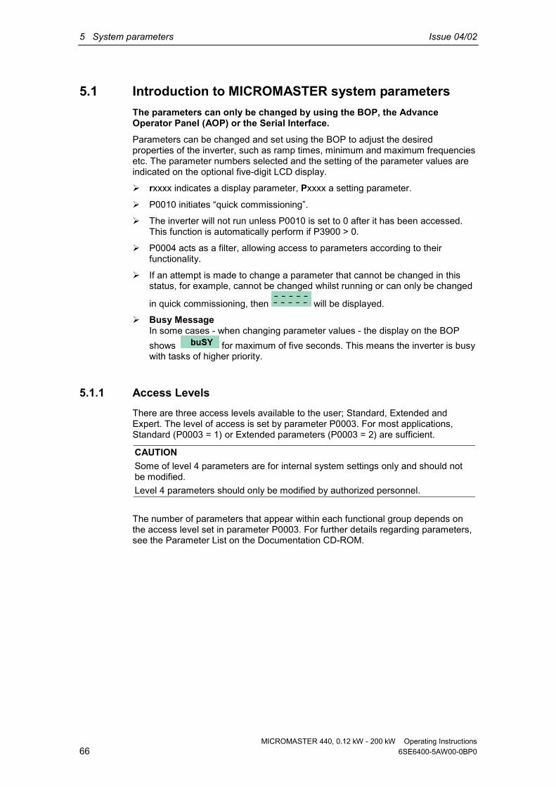
5 System parameters Issue 04/02
MICROMASTER 440, 0.12 kW - 200 kW Operating Instructions66 6SE6400-5AW00-0BP0
5.1 Introduction to MICROMASTER system parametersThe parameters can only be changed by using the BOP, the AdvanceOperator Panel (AOP) or the Serial Interface.Parameters can be changed and set using the BOP to adjust the desiredproperties of the inverter, such as ramp times, minimum and maximum frequenciesetc. The parameter numbers selected and the setting of the parameter values areindicated on the optional five-digit LCD display.
rxxxx indicates a display parameter, Pxxxx a setting parameter.
P0010 initiates “quick commissioning”.
The inverter will not run unless P0010 is set to 0 after it has been accessed.This function is automatically perform if P3900 > 0.
P0004 acts as a filter, allowing access to parameters according to theirfunctionality.
If an attempt is made to change a parameter that cannot be changed in thisstatus, for example, cannot be changed whilst running or can only be changed
in quick commissioning, then will be displayed.
Busy MessageIn some cases - when changing parameter values - the display on the BOPshows for maximum of five seconds. This means the inverter is busywith tasks of higher priority.
5.1.1 Access LevelsThere are three access levels available to the user; Standard, Extended andExpert. The level of access is set by parameter P0003. For most applications,Standard (P0003 = 1) or Extended parameters (P0003 = 2) are sufficient.
CAUTIONSome of level 4 parameters are for internal system settings only and should notbe modified.Level 4 parameters should only be modified by authorized personnel.
The number of parameters that appear within each functional group depends onthe access level set in parameter P0003. For further details regarding parameters,see the Parameter List on the Documentation CD-ROM.

Issue 04/02 5 System parameters
MICROMASTER 440, 0.12 kW - 200 kW Operating Instructions6SE6400-5AW00-0BP0 67
5.2 Parameter overview
P0004 = 5TechnologyApplication / units
P0004 = 2Inverter Unit
P0004 = 3Motor Data
P0004 = 7Commands andDigital I/O
P0004 = 8Analogue I/O
P0004 = 10Setpoint Channel &Ramp Generator
P0004 = 12Drive Features
P0004 = 13Motor Control
P0004 = 20Communication
P0004 = 21Alarms, Warnings &Monitoring
P0004 = 22PI Controller
P0004 = 4Speed sensor
P0004 = 0(no filter function)allows direct accessto the parameters.For BOP and AOPdepending on theselected access level
P0004 = 2Inverter Unit
P000
3 = 1, Access Level Standard
P0004 = 2, P0003 = 1Parameters level 1concerning the inverter unit
P0004 = 2, P0003 = 2Parameters level 1 and 2
concerning the inverter unit
P0004 = 2, P0003 = 4Parameters level 1, 2, 3 and 4
concerning the inverter unit
P0004 = 2, P0003 = 3,Parameters level 1, 2 and 3concerning the inverter unit
P000
3 = 2
, Access Level ExtendedP0
003
= 3,
Access Level Expert
P0003
= 4,
Access Level Service
Figure 5-1 Parameter Overview

5 System parameters Issue 04/02
MICROMASTER 440, 0.12 kW - 200 kW Operating Instructions68 6SE6400-5AW00-0BP0
5.3 Parameter list (short form)Explanatory information on following table:
Default: Factory setting
Level: Access level
DS Inverter status (Drive State), indicates the inverter state in which aparameter can be modified (see P0010).
♦ C Commissioning♦ U Run♦ T Ready to run
QC Quick Commissioning♦ Q Parameter can be modified in the Quick Commissioning state.♦ N Parameter cannot be modified in the Quick Commissioning state.
AlwaysPar. No. Parametername Default Level DS QCr0000 Drive display - 1 - -
P0003 User access level 1 1 CUT NP0004 Parameter filter 0 1 CUT NP0010 Commissioning parameter 0 1 CT NP0014[3] Store mode 0 3 UT NP0199 Equipment system number 0 2 UT N
Quick CommissioningPar. No. Parametername Default Level DS QCP0100 Europe / North America 0 1 C QP3900 End of quick commissioning 0 1 C Q
Parameter ResetPar.-No. Parametername Default Level DS QCP0970 Factory reset 0 1 C N
Technological functionsPar.-No. Parametername Default Level DS QCP0500[3] Technological application 0 3 CT Q
Inverter Unit (P0004 = 2)Par. No. Parametername Default Level DS QCr0018 Firmware version - 1 - -
r0026[1] CO: Act. DC-link voltage - 2 - -r0039 CO: Energy consumpt. meter [kWh] - 2 - -P0040 Reset energy consumption meter 0 2 CT Nr0037[5] CO: Inverter temperature [°C] - 3 - -r0070 CO: Act. DC-link voltage - 3 - -r0200 Act. power stack code number - 3 - -P0201 Power stack code number 0 3 C N

Issue 04/02 5 System parameters
MICROMASTER 440, 0.12 kW - 200 kW Operating Instructions6SE6400-5AW00-0BP0 69
Par. No. Parametername Default Level DS QCr0203 Act. inverter type - 3 - -r0204 Power stack features - 3 - -P0205 Inverter application 0 3 C Qr0206 Rated inverter power [kW] / [hp] - 2 - -r0207 Rated inverter current - 2 - -
r0208 Rated inverter voltage - 2 - -r0209 Maximum inverter current - 2 - -P0210 Supply voltage 230 3 CT Nr0231[2] Max. cable length - 3 - -P0290 Inverter overload reaction 2 3 CT NP0292 Inverter overload warning 15 3 CUT N
P1800 Pulse frequency 4 2 CUT Nr1801 CO: Act. pulse frequency - 3 - -P1802 Modulator mode 0 3 CUT NP1820[3] Reverse output phase sequence 0 2 CT NP1911 No. of phase to be identified 3 2 CT Nr1925 Identified on-state voltage - 2 - -r1926 Ident. gating unit dead time - 2 - -
Motor Data (P0004 = 3)Par. No. Parametername Default Level DS QCr0035[3] CO: Act. Motor temperature - 2 - -P0300[3] Select motor type 1 2 C Q
P0304[3] Rated motor voltage 230 1 C QP0305[3] Rated motor current 3.25 1 C QP0307[3] Rated motor power 0.75 1 C QP0308[3] Rated motor cosPhi 0.000 2 C QP0309[3] Rated motor efficiency 0.0 2 C QP0310[3] Rated motor frequency 50.00 1 C QP0311[3] Rated motor speed 0 1 C Q
r0313[3] Motor pole pairs - 3 - -P0320[3] Motor magnetizing current 0.0 3 CT Qr0330[3] Rated motor slip - 3 - -r0331[3] Rated magnetization current - 3 - -r0332[3] Rated power factor - 3 - -r0333[3] Rated motor torque - 3 - -
P0335[3] Motor cooling 0 2 CT QP0340[3] Calculation of motor parameters 0 2 CT NP0341[3] Motor inertia [kg*m^2] 0.00180 3 CUT NP0342[3] Total/motor inertia ratio 1.000 3 CUT NP0344[3] Motor weight 9.4 3 CUT Nr0345[3] Motor start-up time - 3 - -
P0346[3] Magnetization time 1.000 3 CUT NP0347[3] Demagnetization time 1.000 3 CUT NP0350[3] Stator resistance (line-to-line) 4.0 2 CUT N

5 System parameters Issue 04/02
MICROMASTER 440, 0.12 kW - 200 kW Operating Instructions70 6SE6400-5AW00-0BP0
Par. No. Parametername Default Level DS QCP0352[3] Cable resistance 0.0 3 CUT Nr0384[3] Rotor time constant - 3 - -r0395 CO: Total stator resistance [%] - 3 - -r0396 CO: Act. Rotor resistance - 3 - -P0601[3] Motor temperature sensor 0 2 CUT N
P0604[3] Threshold motor temperature 130.0 2 CUT NP0610[3] Motor I2t temperature reaction 2 3 CT NP0625[3] Ambient motor temperature 20.0 3 CUT NP0640[3] Motor overload factor [%] 150.0 2 CUT QP1910 Select motor data identification 0 2 CT Qr1912[3] Identified stator resistance - 2 - -
r1913[3] Identified rotor time constant - 2 - -r1914[3] Ident. Total leakage inductance - 2 - -r1915[3] Ident. Nom. Stator inductance - 2 - -r1916[3] Identified stator inductance 1 - 2 - -r1917[3] Identified stator inductance 2 - 2 - -r1918[3] Identified stator inductance 3 - 2 - -r1919[3] Identified stator inductance 4 - 2 - -
r1920[3] Identified dyn. Leak. Inductance - 2 - -P1960 Speed control optimisation 0 3 CT Q
Commands and Digital I/O (P0004 = 7)Par. No. Parametername Default Level DS QCR0002 Drive state - 2 - -r0019 CO/BO: BOP control word - 3 - -
r0050 CO: Active command data set - 2 - -r0052 CO/BO: Act. Status word 1 - 2 - -r0051[2] CO: Active drive data set (DDS) - 2 - -r0053 CO/BO: Act. Status word 2 - 2 - -r0054 CO/BO: Act. Control word 1 - 3 - -r0055 CO/BO: Add. Act. Control word - 3 - -
r0403 CO/BO: Encoder status word - 2 - -P0700[3] Selection of command source 2 1 CT QP0701[3] Function of digital input 1 1 2 CT NP0702[3] Function of digital input 2 12 2 CT NP0703[3] Function of digital input 3 9 2 CT NP0704[3] Function of digital input 4 15 2 CT N
P0705[3] Function of digital input 5 15 2 CT NP0706[3] Function of digital input 6 15 2 CT NP0707[3] Function of digital input 7 0 2 CT NP0708[3] Function of digital input 8 0 2 CT Nr0720 Number of digital inputs - 3 - -r0722 CO/BO: Binary input values - 2 - -P0719[3] Selection of cmd. & freq. Setp. 0 3 CT N
P0724 Debounce time for digital inputs 3 3 CT N

Issue 04/02 5 System parameters
MICROMASTER 440, 0.12 kW - 200 kW Operating Instructions6SE6400-5AW00-0BP0 71
Par. No. Parametername Default Level DS QCP0725 PNP / NPN digital inputs 1 3 CT N
r0730 Number of digital outputs - 3 - -P0731[3] BI: Function of digital output 1 52:3 2 CUT NP0732[3] BI: Function of digital output 2 52:7 2 CUT NP0733[3] BI: Function of digital output 3 0:0 2 CUT Nr0747 CO/BO: State of digital outputs - 3 - -P0748 Invert digital outputs 0 3 CUT N
P0800[3] BI: Download parameter set 0 0 :0 3 CT NP0801[3] BI: Download parameter set 1 0 :0 3 CT NP0810 BI: CDS bit 0 (Local / Remote) 0:0 2 CUT NP0811 BI: CDS bit 1 0:0 2 CUT NP0809[3] Copy command data set (CDS) 0 2 CT NP0820 BI: DDS bit 0 0 :0 3 CT N
P0821 BI: DDS bit 1 0 :0 3 CT NP0819[3] Copy drive data set (DDS) 0 2 CT NP0840[3] BI: ON/OFF1 722 :0 3 CT NP0842[3] BI: ON reverse/OFF1 0 :0 3 CT NP0844[3] BI: 1. OFF2 1 :0 3 CT NP0845[3] BI: 2. OFF2 19 :1 3 CT N
P0848[3] BI: 1. OFF3 1 :0 3 CT NP0849[3] BI: 2. OFF3 1 :0 3 CT NP0852[3] BI: Pulse enable 1:0 3 CT NP1020[3] BI: Fixed freq. Selection Bit 0 0 :0 3 CT NP1021[3] BI: Fixed freq. Selection Bit 1 0 :0 3 CT NP1022[3] BI: Fixed freq. Selection Bit 2 0 :0 3 CT NP1023[3] BI: Fixed freq. Selection Bit 3 722 :3 3 CT N
P1026[3] BI: Fixed freq. Selection Bit 4 722 :4 3 CT NP1028[3] BI: Fixed freq. Selection Bit 5 722 :5 3 CT NP1035[3] BI: Enable MOP (UP-command) 19 :13 3 CT NP1036[3] BI: Enable MOP (DOWN-command) 19 :14 3 CT NP1055[3] BI: Enable JOG right 0 :0 3 CT NP1056[3] BI: Enable JOG left 0 :0 3 CT N
P1074[3] BI: Disable additional setpoint 0:0 3 CUT NP1110[3] BI: Inhibit neg. freq. Setpoint 0 :0 3 CT NP1113[3] BI : Reverse 722 :1 3 CT NP1124[3] BI: Enable JOG ramp times 0 :0 3 CT NP1140[3] BI: RFG enable 1 :0 3 CT NP1141[3] BI: RFG start 1 :0 3 CT N
P1142[3] BI: RFG enable setpoint 1 :0 3 CT NP1230[3] BI: Enable DC braking 0:0 3 CUT NP2103[3] BI: 1. Faults acknowledgement 722 :2 3 CT NP2104[3] BI: 2. Faults acknowledgement 0 :0 3 CT NP2106[3] BI : External fault 1 :0 3 CT NP2220[3] BI: Fixed PID setp. Select Bit 0 0 :0 3 CT N
P2221[3] BI: Fixed PID setp. Select Bit 1 0 :0 3 CT N

5 System parameters Issue 04/02
MICROMASTER 440, 0.12 kW - 200 kW Operating Instructions72 6SE6400-5AW00-0BP0
Par. No. Parametername Default Level DS QCP2222[3] BI: Fixed PID setp. Select Bit 2 0 :0 3 CT N
P2223[3] BI: Fixed PID setp. Select Bit 3 722 :3 3 CT NP2226[3] BI: Fixed PID setp. Select Bit 4 722 :4 3 CT NP2228[3] BI: Fixed PID setp. Select Bit 5 722 :5 3 CT NP2235[3] BI: Enable PID-MOP (UP-cmd) 19 :13 3 CT NP2236[3] BI: Enable PID-MOP (DOWN-cmd) 19 :14 3 CT N
Analogue I/O (P0004 = 8)Par. No. Parametername Default Level DS QCP0295 Inverter fan off delay time 0 3 CUT Nr0750 Number of ADCs - 3 - -r0752[2] Act. input of ADC [V] or [mA] - 2 - -P0753[2] Smooth time ADC 3 3 CUT Nr0754[2] Act. ADC value after scaling [%] - 2 - -
r0755[2] CO: Act. ADC after scal. [4000h] - 2 - -P0756[2] Type of ADC 0 2 CT NP0757[2] Value x1 of ADC scaling [V / mA] 0 2 CUT NP0758[2] Value y1 of ADC scaling 0.0 2 CUT NP0759[2] Value x2 of ADC scaling [V / mA] 10 2 CUT NP0760[2] Value y2 of ADC scaling 100.0 2 CUT N
P0761[2] Width of ADC deadband [V / mA] 0 2 CUT NP0762[2] Delay for loss of signal action 10 3 CUT Nr0770 Number of DACs - 3 - -P0771[2] CI: DAC 21:0 2 CUT NP0773[2] Smooth time DAC 2 2 CUT Nr0774[2] Act. DAC value [V] or [mA] - 2 - -P0776[2] Type of DAC 0 2 CT N
P0777[2] Value x1 of DAC scaling 0.0 2 CUT NP0778[2] Value y1 of DAC scaling 0 2 CUT NP0779[2] Value x2 of DAC scaling 100.0 2 CUT NP0780[2] Value y2 of DAC scaling 20 2 CUT NP0781[2] Width of DAC deadband 0 2 CUT N
Setpoint Channel and Ramp Generator (P0004 = 10)Par. No. Parametername Default Level DS QCP1000[3] Selection of frequency setpoint 2 1 CT QP1001[3] Fixed frequency 1 0.00 2 CUT NP1002[3] Fixed frequency 2 5.00 2 CUT NP1003[3] Fixed frequency 3 10.00 2 CUT NP1004[3] Fixed frequency 4 15.00 2 CUT N
P1005[3] Fixed frequency 5 20.00 2 CUT NP1006[3] Fixed frequency 6 25.00 2 CUT NP1007[3] Fixed frequency 7 30.00 2 CUT NP1008[3] Fixed frequency 8 35.00 2 CUT NP1009[3] Fixed frequency 9 40.00 2 CUT N

Issue 04/02 5 System parameters
MICROMASTER 440, 0.12 kW - 200 kW Operating Instructions6SE6400-5AW00-0BP0 73
Par. No. Parametername Default Level DS QCP1010[3] Fixed frequency 10 45.00 2 CUT N
P1011[3] Fixed frequency 11 50.00 2 CUT NP1012[3] Fixed frequency 12 55.00 2 CUT NP1013[3] Fixed frequency 13 60.00 2 CUT NP1016 Fixed frequency mode – Bit 0 1 3 CT NP1014[3] Fixed frequency 14 65.00 2 CUT NP1017 Fixed frequency mode – Bit 1 1 3 CT N
P1015[3] Fixed frequency 15 65.00 2 CUT NP1018 Fixed frequency mode – Bit 2 1 3 CT NP1019 Fixed frequency mode – Bit 3 1 3 CT Nr1024 CO: Act. Fixed frequency - 3 - -P1025 Fixed frequency mode – Bit 4 1 3 CT NP1027 Fixed frequency mode – Bit 5 1 3 CT N
P1032 Inhibit reverse direction of MOP 1 2 CT NP1031[3] Setpoint memory of the MOP 0 2 CUT NP1040[3] Setpoint of the MOP 5.00 2 CUT Nr1050 CO: Act. Output freq. Of the MOP - 3 - -P1058[3] JOG frequency right 5.00 2 CUT NP1059[3] JOG frequency left 5.00 2 CUT N
P1060[3] JOG ramp-up time 10.00 2 CUT NP1061[3] JOG ramp-down time 10.00 2 CUT NP1070[3] CI : Main setpoint 755:0 3 CT NP1071[3] CI : Main setpoint scaling 1:0 3 CT NP1075[3] CI : Additional setpoint 0:0 3 CT Nr1078 CO: Total frequency setpoint - 3 - -P1076[3] CI: Additional setpoint scaling 1:0 3 CT N
r1079 CO: Selected frequency setpoint - 3 - -P1080[3] Min. frequency 0.00 1 CUT QP1082[3] Max. frequency 50.00 1 CT QP1091[3] Skip frequency 1 0.00 3 CUT NP1092[3] Skip frequency 2 0.00 3 CUT NP1093[3] Skip frequency 3 0.00 3 CUT N
P1094[3] Skip frequency 4 0.00 3 CUT NP1101[3] Skip frequency bandwidth 2.00 3 CUT Nr1114 CO: Freq. Setp. After dir. Ctrl. - 3 - -r1119 CO: Freq. Setpoint before RFG - 3 - -P1120[3] Ramp-up time 10.00 1 CUT QP1121[3] Ramp-down time 10.00 1 CUT Q
P1130[3] Ramp-up initial rounding time 0.00 2 CUT NP1131[3] Ramp-up final rounding time 0.00 2 CUT NP1132[3] Ramp-down initial rounding time 0.00 2 CUT NP1133[3] Ramp-down final rounding time 0.00 2 CUT NP1134[3] Rounding type 0 2 CUT NP1135[3] OFF3 ramp-down time 5.00 2 CUT Q
r1170 CO: Frequency setpoint after RFG - 3 - -

5 System parameters Issue 04/02
MICROMASTER 440, 0.12 kW - 200 kW Operating Instructions74 6SE6400-5AW00-0BP0
Par. No. Parametername Default Level DS QCP1257[3] Freq limit for kinetic buffering 2.5 3 CUT N
Drive Features (P0004 = 12)Par. No. Parametername Default Level DS QCP0006 Display mode 2 3 CUT NP0007 Backlight delay time 0 3 CUT NP0005[3] Display selection 21 2 CUT NP0011 Lock for user defined parameter 0 3 CUT N
P0012 Key for user defined parameter 0 3 CUT NP0013[20] User defined parameter 0 3 CUT NP1200 Flying start 0 2 CUT NP1202[3] Motor-current: Flying start 100 3 CUT Nr1205 Status word: Flying start SLVC - 3 - -P1203[3] Search rate: Flying start 100 3 CUT N
P1210 Automatic restart 1 2 CUT NP1211 Number of restart attempts 3 3 CUT NP1215 Holding brake enable 0 2 T NP1216 Holding brake release delay 1.0 2 T NP1217 Holding time after ramp down 1.0 2 T NP1232[3] DC braking current 100 2 CUT N
P1233[3] Duration of DC braking 0 2 CUT NP1234[3] DC braking start frequency 650.00 2 CUT NP1237 Dynamic braking 0 2 CUT NP1236[3] Compound braking current 0 2 CUT Nr1242 CO: Switch-on level of Vdc-max - 3 - -P1240[3] Configuration of Vdc controller 1 3 CT NP1243[3] Dynamic factor of Vdc-max 100 3 CUT N
P1245[3] Switch on level kin. Buffering 76 3 CUT Nr1246[3] CO:Switch-on level kin buffering - 3 - -P1247[3] Dyn. Factor of kinetic buffering 100 3 CUT NP1254 Auto detect Vdc switch-on levels 1 3 CT NP1253[3] Vdc-controller output limitation 10 3 CUT NP1256[3] Reaction of kinetic buffering 0 3 CT N
Motor Control (P0004 = 13)Par. No. Parametername Default Level DS QCr0020 CO: Act. frequency setpoint - 3 - -r0021 CO: Act. frequency - 2 - -
r0022 Act. rotor speed - 3 - -r0024 CO: Act. output frequency - 3 - -r0025 CO: Act. output voltage - 2 - -r0027 CO: Act. output current - 2 - -r0029 CO: Flux gen. current - 3 - -r0030 CO: Torque gen. current - 3 - -r0031 CO: Act. torque - 2 - -
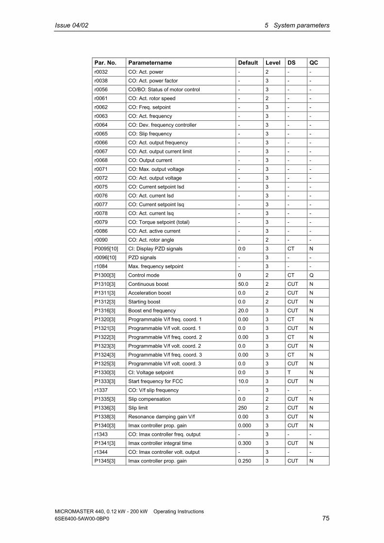
Issue 04/02 5 System parameters
MICROMASTER 440, 0.12 kW - 200 kW Operating Instructions6SE6400-5AW00-0BP0 75
Par. No. Parametername Default Level DS QCr0032 CO: Act. power - 2 - -r0038 CO: Act. power factor - 3 - -r0056 CO/BO: Status of motor control - 3 - -r0061 CO: Act. rotor speed - 2 - -r0062 CO: Freq. setpoint - 3 - -
r0063 CO: Act. frequency - 3 - -r0064 CO: Dev. frequency controller - 3 - -r0065 CO: Slip frequency - 3 - -r0066 CO: Act. output frequency - 3 - -r0067 CO: Act. output current limit - 3 - -r0068 CO: Output current - 3 - -
r0071 CO: Max. output voltage - 3 - -r0072 CO: Act. output voltage - 3 - -r0075 CO: Current setpoint Isd - 3 - -r0076 CO: Act. current Isd - 3 - -r0077 CO: Current setpoint Isq - 3 - -r0078 CO: Act. current Isq - 3 - -r0079 CO: Torque setpoint (total) - 3 - -
r0086 CO: Act. active current - 3 - -r0090 CO: Act. rotor angle - 2 - -P0095[10] CI: Display PZD signals 0:0 3 CT Nr0096[10] PZD signals - 3 - -r1084 Max. frequency setpoint - 3 - -P1300[3] Control mode 0 2 CT Q
P1310[3] Continuous boost 50.0 2 CUT NP1311[3] Acceleration boost 0.0 2 CUT NP1312[3] Starting boost 0.0 2 CUT NP1316[3] Boost end frequency 20.0 3 CUT NP1320[3] Programmable V/f freq. coord. 1 0.00 3 CT NP1321[3] Programmable V/f volt. coord. 1 0.0 3 CUT N
P1322[3] Programmable V/f freq. coord. 2 0.00 3 CT NP1323[3] Programmable V/f volt. coord. 2 0.0 3 CUT NP1324[3] Programmable V/f freq. coord. 3 0.00 3 CT NP1325[3] Programmable V/f volt. coord. 3 0.0 3 CUT NP1330[3] CI: Voltage setpoint 0:0 3 T NP1333[3] Start frequency for FCC 10.0 3 CUT N
r1337 CO: V/f slip frequency - 3 - -P1335[3] Slip compensation 0.0 2 CUT NP1336[3] Slip limit 250 2 CUT NP1338[3] Resonance damping gain V/f 0.00 3 CUT NP1340[3] Imax controller prop. gain 0.000 3 CUT Nr1343 CO: Imax controller freq. output - 3 - -P1341[3] Imax controller integral time 0.300 3 CUT N
r1344 CO: Imax controller volt. output - 3 - -P1345[3] Imax controller prop. gain 0.250 3 CUT N

5 System parameters Issue 04/02
MICROMASTER 440, 0.12 kW - 200 kW Operating Instructions76 6SE6400-5AW00-0BP0
Par. No. Parametername Default Level DS QCP1346[3] Imax controller integral time 0.300 3 CUT NP1350[3] Voltage soft start 0 3 CUT NP1400[3] Configuration of speed control 1 3 CUT Nr1407 CO/BO: Status 2 of motor control - 3 - -r1438 CO: Freq. setpoint to controller - 3 - -
P1452[3] Filter time for act.speed (SLVC) 4 3 CUT NP1460[3] Gain speed controller 3.0 2 CUT NP1462[3] Integral time speed controller 400 2 CUT NP1470[3] Gain speed controller (SLVC) 3.0 2 CUT NP1472[3] Integral time n-ctrl. (SLVC) 400 2 CUT NP1477[3] BI: Set integrator of n-ctrl. 0:0 3 CUT N
P1478[3] CI: Set integrator value n-ctrl. 0:0 3 UT Nr1482 CO: Integral output of n-ctrl. - 3 - -r1490 CO: Droop frequency - 3 - -P1488[3] Droop input source 0 3 CUT NP1489[3] Droop scaling 0.05 3 CUT NP1492[3] Enable droop 0 3 CUT NP1496[3] Scaling accel. precontrol 0.0 3 CUT N
P1499[3] Scaling accel. torque control 100.0 3 CUT NP1500[3] Selection of torque setpoint 0 2 CT QP1501[3] BI: Change to torque control 0:0 3 CT NP1503[3] CI: Torque setpoint 0:0 3 T Nr1508 CO: Torque setpoint - 2 - -P1511[3] CI: Additional torque setpoint 0:0 3 T N
r1515 CO: Additional torque setpoint - 2 - -r1518 CO: Acceleration torque - 3 - -P1520[3] CO: Upper torque limit 5.13 2 CUT NP1521[3] CO: Lower torque limit -5.13 2 CUT NP1522[3] CI: Upper torque limit 1520:0 3 T NP1523[3] CI: Lower torque limit 1521:0 3 T N
r1526 CO: Upper torque limitation - 3 - -r1527 CO: Lower torque limitation - 3 - -P1525[3] Scaling lower torque limit 100.0 3 CUT NP1530[3] Motoring power limitation 0.75 2 CUT NP1531[3] Regenerative power limitation -0.75 2 CUT Nr1538 CO: Upper torque limit (total) - 2 - -
r1539 CO: Lower torque limit (total) - 2 - -P1570[3] CO: Fixed value flux setpoint 100.0 2 CUT NP1574[3] Dynamic voltage headroom 10 3 CUT NP1580[3] Efficiency optimization 0 2 CUT NP1582[3] Smooth time for flux setpoint 15 3 CUT Nr1598 CO: Flux setpoint (total) - 3 - -P1596[3] Int. time field weak. controller 50 3 CUT N
P1610[3] Continuous torque boost (SLVC) 50.0 2 CUT NP1611[3] Acc. torque boost (SLVC) 0.0 2 CUT N

Issue 04/02 5 System parameters
MICROMASTER 440, 0.12 kW - 200 kW Operating Instructions6SE6400-5AW00-0BP0 77
Par. No. Parametername Default Level DS QCP1740 Gain for oscillation damping 0.000 3 CUT Nr1751 Status word of motor model - 3 - -P1750[3] Control word of motor model 1 3 CUT NP1755[3] Start-freq. motor model (SLVC) 5.0 3 CUT NP1756[3] Hyst.-freq. motor model (SLVC) 50.0 3 CUT N
P1758[3] T(wait) transit to feed-fwd-mode 1500 3 CUT NP1759[3] T(wait) for n-adaption to settle 100 3 CUT NP1764[3] Kp of n-adaption (SLVC) 0.2 3 CUT Nr1770 CO: Prop. output of n-adaption - 3 - -r1771 CO: Int. output of n-adaption - 3 - -r1782 Output of Rs-adaptation - 3 - -
P1780[3] Control word of Rs/Rr-adaption 3 3 CUT Nr1787 Output of Xm-adaption - 3 - -P2480[3] Position mode 1 3 CT NP2481[3] Gearbox ratio input 1.00 3 CT NP2482[3] Gearbox ratio output 1.00 3 CT NP2484[3] No. of shaft turns = 1 Unit 1.0 3 CUT Nr2489 Act. number of shaft revolutions - 3 - -
P2487[3] Positional error trim value 0.00 3 CUT NP2488[3] No. final shaft turns = 1 Unit 1.0 3 CUT N
Communication (P0004 = 20)Par. No. Parametername Default Level DS QCP0918 CB address 3 2 CT NP0927 Parameter changeable via 15 2 CUT Nr0965 Profibus profile - 3 - -r0967 Control word 1 - 3 - -r0968 Status word 1 - 3 - -r0964[5] Firmware version data - 3 - -
P0971 Transfer data from RAM to EEPROM 0 3 CUT NP2000[3] Reference frequency 50.00 2 CT NP2001[3] Reference voltage 1000 3 CT NP2002[3] Reference current 0.10 3 CT NP2003[3] Reference torque 0.75 3 CT Nr2004[3] Reference power - 3 - -
P2009[2] USS normalization 0 3 CT NP2010[2] USS baudrate 6 2 CUT NP2011[2] USS address 0 2 CUT NP2012[2] USS PZD length 2 3 CUT NP2013[2] USS PKW length 127 3 CUT NP2014[2] USS telegram off time 0 3 CT N
r2015[8] CO: PZD from BOP link (USS) - 3 - -P2016[8] CI: PZD to BOP link (USS) 52:0 3 CT Nr2018[8] CO: PZD from COM link (USS) - 3 - -r2024[2] USS error-free telegrams - 3 - -

5 System parameters Issue 04/02
MICROMASTER 440, 0.12 kW - 200 kW Operating Instructions78 6SE6400-5AW00-0BP0
Par. No. Parametername Default Level DS QCP2019[8] CI: PZD to COM link (USS) 52:0 3 CT Nr2025[2] USS rejected telegrams - 3 - -r2026[2] USS character frame error - 3 - -r2027[2] USS overrun error - 3 - -
r2028[2] USS parity error - 3 - -r2029[2] USS start not identified - 3 - -r2030[2] USS BCC error - 3 - -r2032 BO: CtrlWrd1 from BOP link (USS) - 3 - -r2031[2] USS length error - 3 - -r2033 BO: CtrlWrd2 from BOP link (USS) - 3 - -
r2036 BO: CtrlWrd1 from COM link (USS) - 3 - -r2037 BO: CtrlWrd2 from COM link (USS) - 3 - -P2040 CB telegram off time 20 3 CT NP2041[5] CB parameter 0 3 CT Nr2050[8] CO: PZD from CB - 3 - -r2053[5] CB identification - 3 - -P2051[8] CI: PZD to CB 52:0 3 CT N
r2054[7] CB diagnosis - 3 - -r2090 BO: Control word 1 from CB - 3 - -r2091 BO: Control word 2 from CB - 3 - -
Alarms, Warnings and Monitoring (P0004 = 21)Par. No. Parametername Default Level DS QCr0947[8] Last fault code - 2 - -
r0948[12] Fault time - 3 - -r0949[8] Fault value - 3 - -P0952 Total number of faults 0 3 CT NP2100[3] Alarm number selection 0 3 CT NP2101[3] Stop reaction value 0 3 CT Nr2110[4] Warning number - 2 - -
P2111 Total number of warnings 0 3 CT Nr2114[2] Run time counter - 3 - -P2115[3] AOP real time clock 0 3 CT NP2150[3] Hysteresis frequency f_hys 3.00 3 CUT NP2151[3] CI: Monitoring speed setpoint 0:0 3 CUT NP2152[3] CI: Act. monitoring speed 0:0 3 CUT N
P2153[3] Time-constant speed filter 5 2 CUT NP2155[3] Threshold frequency f_1 30.00 3 CUT NP2156[3] Delay time of threshold freq f_1 10 3 CUT NP2157[3] Threshold frequency f_2 30.00 2 CUT NP2158[3] Delay time of threshold freq f_2 10 2 CUT NP2159[3] Threshold frequency f_3 30.00 2 CUT NP2160[3] Delay time of threshold freq f_3 10 2 CUT N
P2161[3] Min. threshold for freq. setp. 3.00 2 CUT NP2162[3] Hysteresis freq. for overspeed 20.00 2 CUT N

Issue 04/02 5 System parameters
MICROMASTER 440, 0.12 kW - 200 kW Operating Instructions6SE6400-5AW00-0BP0 79
Par. No. Parametername Default Level DS QCP2163[3] Entry freq. for perm. deviation 3.00 2 CUT N
P2164[3] Hysteresis frequency deviation 3.00 3 CUT NP2165[3] Delay time permitted deviation 10 2 CUT NP2166[3] Delay time ramp up completed 10 2 CUT NP2167[3] Switch-off frequency f_off 1.00 3 CUT NP2168[3] Delay time T_off 10 3 CUT Nr2169 CO: Act. filtered frequency - 2 - -
P2170[3] Threshold current I_thresh 100.0 3 CUT NP2171[3] Delay time current 10 3 CUT NP2172[3] Threshold DC-link voltage 800 3 CUT NP2173[3] Delay time DC-link voltage 10 3 CUT NP2174[3] Torque threshold T_thresh 5.13 2 CUT NP2176[3] Delay time for torque threshold 10 2 CUT N
P2177[3] Delay time for motor is blocked 10 2 CUT NP2178[3] Delay time for motor pulled out 10 2 CUT NP2179 Current limit for no load ident. 3.0 3 CUT NP2180 Delay time for no load ident. 2000 3 CUT NP2181[3] Belt failure detection mode 0 2 CT NP2182[3] Belt threshold frequency 1 5.00 3 CUT N
P2183[3] Belt threshold frequency 2 30.00 2 CUT NP2184[3] Belt threshold frequency 3 50.00 2 CUT NP2185[3] Upper torque threshold 1 99999.0 2 CUT NP2186[3] Lower torque threshold 1 0.0 2 CUT NP2187[3] Upper torque threshold 2 99999.0 2 CUT NP2188[3] Lower torque threshold 2 0.0 2 CUT NP2189[3] Upper torque threshold 3 99999.0 2 CUT N
P2190[3] Lower torque threshold 3 0.0 2 CUT NP2192[3] Time delay for belt failure 10 2 CUT Nr2197 CO/BO: Monitoring word 1 - 2 - -r2198 CO/BO: Monitoring word 2 - 2 - -
PI Controller (P0004 = 22)Par. No. Parametername Default Level DS QCP2200[3] BI: Enable PID controller 0:0 2 CUT NP2201[3] Fixed PID setpoint 1 0.00 2 CUT NP2202[3] Fixed PID setpoint 2 10.00 2 CUT NP2203[3] Fixed PID setpoint 3 20.00 2 CUT NP2204[3] Fixed PID setpoint 4 30.00 2 CUT NP2205[3] Fixed PID setpoint 5 40.00 2 CUT N
P2206[3] Fixed PID setpoint 6 50.00 2 CUT NP2207[3] Fixed PID setpoint 7 60.00 2 CUT NP2208[3] Fixed PID setpoint 8 70.00 2 CUT NP2209[3] Fixed PID setpoint 9 80.00 2 CUT NP2210[3] Fixed PID setpoint 10 90.00 2 CUT NP2211[3] Fixed PID setpoint 11 100.00 2 CUT N

5 System parameters Issue 04/02
MICROMASTER 440, 0.12 kW - 200 kW Operating Instructions80 6SE6400-5AW00-0BP0
Par. No. Parametername Default Level DS QCP2212[3] Fixed PID setpoint 12 110.00 2 CUT N
P2213[3] Fixed PID setpoint 13 120.00 2 CUT NP2214[3] Fixed PID setpoint 14 130.00 2 CUT NP2215[3] Fixed PID setpoint 15 130.00 2 CUT NP2216 Fixed PID setpoint mode - Bit 0 1 3 CT NP2217 Fixed PID setpoint mode - Bit 1 1 3 CT NP2218 Fixed PID setpoint mode - Bit 2 1 3 CT N
P2219 Fixed PID setpoint mode - Bit 3 1 3 CT Nr2224 CO: Act. fixed PID setpoint - 2 - -P2225 Fixed PID setpoint mode - Bit 4 1 3 CT NP2227 Fixed PID setpoint mode - Bit 5 1 3 CT NP2231[3] Setpoint memory of PID-MOP 0 2 CUT NP2232 Inhibit rev. direct. of PID-MOP 1 2 CT N
P2240[3] Setpoint of PID-MOP 10.00 2 CUT Nr2250 CO: Output setpoint of PID-MOP - 2 - -P2251 PID mode 0 3 CT NP2253[3] CI: PID setpoint 0:0 2 CUT NP2254[3] CI: PID trim source 0:0 3 CUT NP2255 PID setpoint gain factor 100.00 3 CUT N
P2256 PID trim gain factor 100.00 3 CUT NP2257 Ramp-up time for PID setpoint 1.00 2 CUT NP2258 Ramp-down time for PID setpoint 1.00 2 CUT Nr2260 CO: PID setpoint after PID-RFG - 2 - -P2261 PID setpoint filter timeconstant 0.00 3 CUT Nr2262 CO: Filtered PID setp. after RFG - 3 - -P2263 PID controller type 0 3 CT N
P2264[3] CI: PID feedback 755:0 2 CUT NP2265 PID feedback filter timeconstant 0.00 2 CUT Nr2266 CO: PID filtered feedback - 2 - -P2267 Max. value for PID feedback 100.00 3 CUT NP2268 Min. value for PID feedback 0.00 3 CUT NP2269 Gain applied to PID feedback 100.00 3 CUT N
P2270 PID feedback function selector 0 3 CUT NP2271 PID transducer type 0 2 CUT Nr2272 CO: PID scaled feedback - 2 - -r2273 CO: PID error - 2 - -P2274 PID derivative time 0.000 2 CUT NP2280 PID proportional gain 3.000 2 CUT N
P2285 PID integral time 0.000 2 CUT NP2291 PID output upper limit 100.00 2 CUT NP2292 PID output lower limit 0.00 2 CUT NP2293 Ramp-up /-down time of PID limit 1.00 3 CUT Nr2294 CO: Act. PID output - 2 - -P2295 Gain applied to PID output 100.00 3 CUT N
P2350 PID autotune enable 0 2 CUT N

Issue 04/02 5 System parameters
MICROMASTER 440, 0.12 kW - 200 kW Operating Instructions6SE6400-5AW00-0BP0 81
Par. No. Parametername Default Level DS QCP2354 PID tuning timeout length 240 3 CUT N
P2355 PID tuning offset 5.00 3 CUT NP2800 Enable FFBs 0 3 CUT NP2801[17] Activate FFBs 0 3 CUT NP2802[14] Activate FFBs 0 3 CUT NP2810[2] BI: AND 1 0:0 3 CUT Nr2811 BO: AND 1 - 3 - -
P2812[2] BI: AND 2 0:0 3 CUT Nr2813 BO: AND 2 - 3 - -P2814[2] BI: AND 3 0:0 3 CUT Nr2815 BO: AND 3 - 3 - -P2816[2] BI: OR 1 0:0 3 CUT Nr2817 BO: OR 1 - 3 - -
P2818[2] BI: OR 2 0:0 3 CUT Nr2819 BO: OR 2 - 3 - -P2820[2] BI: OR 3 0:0 3 CUT Nr2821 BO: OR 3 - 3 - -P2822[2] BI: XOR 1 0:0 3 CUT Nr2823 BO: XOR 1 - 3 - -
P2824[2] BI: XOR 2 0:0 3 CUT Nr2825 BO: XOR 2 - 3 - -P2826[2] BI: XOR 3 0:0 3 CUT Nr2827 BO: XOR 3 - 3 - -P2828 BI: NOT 1 0:0 3 CUT Nr2829 BO: NOT 1 - 3 - -P2830 BI: NOT 2 0:0 3 CUT N
r2831 BO: NOT 2 - 3 - -P2832 BI: NOT 3 0:0 3 CUT Nr2833 BO: NOT 3 - 3 - -P2834[4] BI: D-FF 1 0:0 3 CUT Nr2835 BO: Q D-FF 1 - 3 - -r2836 BO: NOT-Q D-FF 1 - 3 - -
P2837[4] BI: D-FF 2 0:0 3 CUT Nr2838 BO: Q D-FF 2 - 3 - -r2839 BO: NOT-Q D-FF 2 - 3 - -P2840[2] BI: RS-FF 1 0:0 3 CUT Nr2841 BO: Q RS-FF 1 - 3 - -r2842 BO: NOT-Q RS-FF 1 - 3 - -
P2843[2] BI: RS-FF 2 0:0 3 CUT Nr2844 BO: Q RS-FF 2 - 3 - -r2845 BO: NOT-Q RS-FF 2 - 3 - -P2846[2] BI: RS-FF 3 0:0 3 CUT Nr2847 BO: Q RS-FF 3 - 3 - -r2848 BO: NOT-Q RS-FF 3 - 3 - -
P2849 BI: Timer 1 0:0 3 CUT N

5 System parameters Issue 04/02
MICROMASTER 440, 0.12 kW - 200 kW Operating Instructions82 6SE6400-5AW00-0BP0
Par. No. Parametername Default Level DS QCP2850 Delay time of timer 1 0 3 CUT N
P2851 Mode timer 1 0 3 CUT Nr2852 BO: Timer 1 - 3 - -r2853 BO: Nout timer 1 - 3 - -P2854 BI: Timer 2 0:0 3 CUT NP2855 Delay time of timer 2 0 3 CUT NP2856 Mode timer 2 0 3 CUT N
r2857 BO: Timer 2 - 3 - -r2858 BO: Nout timer 2 - 3 - -P2859 BI: Timer 3 0:0 3 CUT NP2860 Delay time of timer 3 0 3 CUT NP2861 Mode timer 3 0 3 CUT Nr2862 BO: Timer 3 - 3 - -
r2863 BO: Nout timer 3 - 3 - -P2864 BI: Timer 4 0:0 3 CUT NP2865 Delay time of timer 4 0 3 CUT NP2866 Mode timer 4 0 3 CUT Nr2867 BO: Timer 4 - 3 - -r2868 BO: Nout timer 4 - 3 - -
P2869[2] CI: ADD 1 755:0 3 CUT Nr2870 CO: ADD 1 - 3 - -P2871[2] CI: ADD 2 755:0 3 CUT Nr2872 CO: ADD 2 - 3 - -P2873[2] CI: SUB 1 755:0 3 CUT Nr2874 CO: SUB 1 - 3 - -P2875[2] CI: SUB 2 755:0 3 CUT N
r2876 CO: SUB 2 - 3 - -P2877[2] CI: MUL 1 755:0 3 CUT Nr2878 CO: MUL 1 - 3 - -P2879[2] CI: MUL 2 755:0 3 CUT Nr2880 CO: MUL 2 - 3 - -P2881[2] CI: DIV 1 755:0 3 CUT N
r2882 CO: DIV 1 - 3 - -P2883[2] CI: DIV 2 755:0 3 CUT Nr2884 CO: DIV 2 - 3 - -P2885[2] CI: CMP 1 755:0 3 CUT Nr2886 BO: CMP 1 - 3 - -P2887[2] CI: CMP 2 755:0 3 CUT N
r2888 BO: CMP 2 - 3 - -P2889 CO: Fixed setpoint 1 in [%] 0 3 CUT NP2890 CO: Fixed setpoint 2 in [%] 0 3 CUT N

Issue 04/02 5 System parameters
MICROMASTER 440, 0.12 kW - 200 kW Operating Instructions6SE6400-5AW00-0BP0 83
EncoderPar. No. Parametername Default Level DS QCP0400[3] Select encoder type 0 2 CT NP0408[3] Encoder pulses per revolution 1024 2 CT N
P0491[3] Reaction on speed signal loss 0 2 CT NP0492[3] Allowed speed difference 10.00 2 CT NP0494[3] Delay speed loss reaction 10 2 CUT N

5 System parameters Issue 04/02
MICROMASTER 440, 0.12 kW - 200 kW Operating Instructions84 6SE6400-5AW00-0BP0
5.4 Command and Drive Datasets - Overview
Command Datasets (CDS)ParNr Parameter nameP0700[3] Selection of command sourceP0701[3] Function of digital input 1
P0702[3] Function of digital input 2P0703[3] Function of digital input 3P0704[3] Function of digital input 4P0705[3] Function of digital input 5P0706[3] Function of digital input 6P0707[3] Function of digital input 7
P0708[3] Function of digital input 8P0719[3] Selection of cmd. & freq. setp.P0731[3] BI: Function of digital output 1P0732[3] BI: Function of digital output 2P0733[3] BI: Function of digital output 3P0800[3] BI: Download parameter set 0
P0801[3] BI: Download parameter set 1P0840[3] BI: ON/OFF1P0842[3] BI: ON reverse/OFF1P0844[3] BI: 1. OFF2P0845[3] BI: 2. OFF2P0848[3] BI: 1. OFF3
P0849[3] BI: 2. OFF3P0852[3] BI: Pulse enableP1000[3] Selection of frequency setpointP1020[3] BI: Fixed freq. selection Bit 0P1021[3] BI: Fixed freq. selection Bit 1P1022[3] BI: Fixed freq. selection Bit 2P1023[3] BI: Fixed freq. selection Bit 3
P1026[3] BI: Fixed freq. selection Bit 4P1028[3] BI: Fixed freq. selection Bit 5P1035[3] BI: Enable MOP (UP-command)P1036[3] BI: Enable MOP (DOWN-command)P1055[3] BI: Enable JOG rightP1056[3] BI: Enable JOG left
P1070[3] CI: Main setpointP1071[3] CI: Main setpoint scalingP1074[3] BI: Disable additional setpointP1075[3] CI: Additional setpointP1076[3] CI: Additional setpoint scalingP1110[3] BI: Inhibit neg. freq. setpoint
P1113[3] BI: ReverseP1124[3] BI: Enable JOG ramp times
ParNr Parameter nameP1140[3] BI: RFG enableP1141[3] BI: RFG start
P1142[3] BI: RFG enable setpointP1230[3] BI: Enable DC brakingP1330[3] CI: Voltage setpointP1477[3] BI: Set integrator of n-ctrl.P1478[3] CI: Set integrator value n-ctrl.P1500[3] Selection of torque setpoint
P1501[3] BI: Change to torque controlP1503[3] CI: Torque setpointP1511[3] CI: Additional torque setpointP1522[3] CI: Upper torque limitP1523[3] CI: Lower torque limitP2103[3] BI: 1. Faults acknowledgement
P2104[3] BI: 2. Faults acknowledgementP2106[3] BI: External faultP2151[3] CI: Monitoring speed setpointP2152[3] CI: Act. monitoring speedP2200[3] BI: Enable PID controllerP2220[3] BI: Fixed PID setp. select Bit 0
P2221[3] BI: Fixed PID setp. select Bit 1P2222[3] BI: Fixed PID setp. select Bit 2P2223[3] BI: Fixed PID setp. select Bit 3P2226[3] BI: Fixed PID setp. select Bit 4P2228[3] BI: Fixed PID setp. select Bit 5P2235[3] BI: Enable PID-MOP (UP-cmd)P2236[3] BI: Enable PID-MOP (DOWN-cmd)
P2253[3] CI: PID setpointP2254[3] CI: PID trim sourceP2264[3] CI: PID feedback

Issue 04/02 5 System parameters
MICROMASTER 440, 0.12 kW - 200 kW Operating Instructions6SE6400-5AW00-0BP0 85
Drive Datasets (DDSNumber Parameter nameP0005[3] Display selectionr0035[3] CO: Act. motor temperatureP0291[3] Inverter protection
P0300[3] Select motor typeP0304[3] Rated motor voltageP0305[3] Rated motor currentP0307[3] Rated motor powerP0308[3] Rated motor cosPhiP0309[3] Rated motor efficiency
P0310[3] Rated motor frequencyP0311[3] Rated motor speedr0313[3] Motor pole pairsP0314[3] Motor pole pair numberP0320[3] Motor magnetizing currentr0330[3] Rated motor slip
r0331[3] Rated magnetization currentr0332[3] Rated power factorr0333[3] Rated motor torqueP0335[3] Motor coolingP0340[3] Calculation of motor parametersP0341[3] Motor inertia [kg*m^2]
P0342[3] Total/motor inertia ratioP0344[3] Motor weightr0345[3] Motor start-up timeP0346[3] Magnetization timeP0347[3] Demagnetization timeP0350[3] Stator resistance (line-to-line)P0352[3] Cable resistance
P0354[3] Rotor resistanceP0356[3] Stator leakage inductanceP0358[3] Rotor leakage inductanceP0360[3] Main inductanceP0362[3] Magnetizing curve flux 1P0363[3] Magnetizing curve flux 2
P0364[3] Magnetizing curve flux 3P0365[3] Magnetizing curve flux 4P0366[3] Magnetizing curve imag 1P0367[3] Magnetizing curve imag 2P0368[3] Magnetizing curve imag 3P0369[3] Magnetizing curve imag 4
r0370[3] Stator resistance [%]r0372[3] Cable resistance [%]r0373[3] Rated stator resistance [%]
Number Parameter namer0374[3] Rotor resistance [%]r0376[3] Rated rotor resistance [%]r0377[3] Total leakage reactance [%]
r0382[3] Main reactance [%]r0384[3] Rotor time constantr0386[3] Total leakage time constantP0400[3] Select encoder typeP0408[3] Encoder pulses per revolutionP0491[3] Reaction on speed signal loss
P0492[3] Allowed speed differenceP0494[3] Delay speed loss reactionP0500[3] Technological applicationP0530[3] Unit for positioning signalP0531[3] Unit conversionP0601[3] Motor temperature sensor
P0604[3] Threshold motor temperatureP0625[3] Ambient motor temperatureP0626[3] Overtemperature stator ironP0627[3] Overtemperature stator windingP0628[3] Overtemperature rotor windingr0630[3] CO: Ambient temperature
r0631[3] CO: Stator iron temperaturer0632[3] CO: Stator winding temperaturer0633[3] CO: Rotor winding temperatureP0640[3] Motor overload factor [%]P1001[3] Fixed frequency 1P1002[3] Fixed frequency 2P1003[3] Fixed frequency 3
P1004[3] Fixed frequency 4P1005[3] Fixed frequency 5P1006[3] Fixed frequency 6P1007[3] Fixed frequency 7P1008[3] Fixed frequency 8P1009[3] Fixed frequency 9
P1010[3] Fixed frequency 10P1011[3] Fixed frequency 11P1012[3] Fixed frequency 12P1013[3] Fixed frequency 13P1014[3] Fixed frequency 14P1015[3] Fixed frequency 15
P1031[3] Setpoint memory of the MOPP1040[3] Setpoint of the MOPP1058[3] JOG frequency right

5 System parameters Issue 04/02
MICROMASTER 440, 0.12 kW - 200 kW Operating Instructions86 6SE6400-5AW00-0BP0
Number Parameter nameP1059[3] JOG frequency leftP1060[3] JOG ramp-up timeP1061[3] JOG ramp-down timeP1080[3] Min. frequencyP1082[3] Max. frequency
P1091[3] Skip frequency 1P1092[3] Skip frequency 2P1093[3] Skip frequency 3P1094[3] Skip frequency 4P1101[3] Skip frequency bandwidthP1120[3] Ramp-up time
P1121[3] Ramp-down timeP1130[3] Ramp-up initial rounding timeP1131[3] Ramp-up final rounding timeP1132[3] Ramp-down initial rounding timeP1133[3] Ramp-down final rounding timeP1134[3] Rounding typeP1135[3] OFF3 ramp-down time
P1202[3] Motor-current: Flying startP1203[3] Search rate: Flying startP1232[3] DC braking currentP1233[3] Duration of DC brakingP1234[3] DC braking start frequencyP1236[3] Compound braking current
P1240[3] Configuration of Vdc controllerP1243[3] Dynamic factor of Vdc-maxP1245[3] Switch on level kin. bufferingr1246[3] CO:Switch-on level kin bufferingP1247[3] Dyn. factor of kinetic bufferingP1250[3] Gain of Vdc-controller
P1251[3] Integration time Vdc-controllerP1252[3] Differential time Vdc-controllerP1253[3] Vdc-controller output limitationP1256[3] Reaction of kinetic bufferingP1257[3] Freq limit for kinetic bufferingP1300[3] Control mode
P1310[3] Continuous boostP1311[3] Acceleration boostP1312[3] Starting boostP1316[3] Boost end frequencyP1320[3] Programmable V/f freq. coord. 1P1321[3] Programmable V/f volt. coord. 1P1322[3] Programmable V/f freq. coord. 2
P1323[3] Programmable V/f volt. coord. 2P1324[3] Programmable V/f freq. coord. 3
Number Parameter nameP1325[3] Programmable V/f volt. coord. 3P1333[3] Start frequency for FCCP1335[3] Slip compensationP1336[3] Slip limitP1338[3] Resonance damping gain V/f
P1340[3] Imax controller prop. gainP1341[3] Imax controller integral timeP1345[3] Imax controller prop. gainP1346[3] Imax controller integral timeP1350[3] Voltage soft startP1400[3] Configuration of speed control
P1442[3] Filter time for act. speedP1452[3] Filter time for act.speed (SLVC)P1460[3] Gain speed controllerP1462[3] Integral time speed controllerP1470[3] Gain speed controller (SLVC)P1472[3] Integral time n-ctrl. (SLVC)P1488[3] Droop input source
P1489[3] Droop scalingP1492[3] Enable droopP1496[3] Scaling accel. precontrolP1499[3] Scaling accel. torque controlP1520[3] CO: Upper torque limitP1521[3] CO: Lower torque limit
P1525[3] Scaling lower torque limitP1530[3] Motoring power limitationP1531[3] Regenerative power limitationP1570[3] CO: Fixed value flux setpointP1574[3] Dynamic voltage headroomP1580[3] Efficiency optimization
P1582[3] Smooth time for flux setpointP1596[3] Int. time field weak. controllerP1610[3] Continuous torque boost (SLVC)P1611[3] Acc. torque boost (SLVC)P1654[3] Smooth time for Isq setpointP1715[3] Gain current controller
P1717[3] Integral time current controllerP1750[3] Control word of motor modelP1755[3] Start-freq. motor model (SLVC)P1756[3] Hyst.-freq. motor model (SLVC)P1758[3] T(wait) transit to feed-fwd-modeP1759[3] T(wait) for n-adaption to settleP1764[3] Kp of n-adaption (SLVC)
P1767[3] Tn of n-adaption (SLVC)P1780[3] Control word of Rs/Rr-adaption

Issue 04/02 5 System parameters
MICROMASTER 440, 0.12 kW - 200 kW Operating Instructions6SE6400-5AW00-0BP0 87
Number Parameter nameP1781[3] Tn of Rs-adaptionP1786[3] Tn of Xm-adaptionP1803[3] Max. modulationP1820[3] Reverse output phase sequenceP1909[3] Ctrl. word of motor data ident.
P2000[3] Reference frequencyP2001[3] Reference voltageP2002[3] Reference currentP2003[3] Reference torquer2004[3] Reference powerP2150[3] Hysteresis frequency f_hys
P2153[3] Time-constant speed filterP2155[3] Threshold frequency f_1P2156[3] Delay time of threshold freq f_1P2157[3] Threshold frequency f_2P2158[3] Delay time of threshold freq f_2P2159[3] Threshold frequency f_3P2160[3] Delay time of threshold freq f_3
P2161[3] Min. threshold for freq. setp.P2162[3] Hysteresis freq. for overspeedP2163[3] Entry freq. for perm. deviationP2164[3] Hysteresis frequency deviationP2165[3] Delay time permitted deviationP2166[3] Delay time ramp up completed
P2167[3] Switch-off frequency f_offP2168[3] Delay time T_offP2170[3] Threshold current I_threshP2171[3] Delay time currentP2172[3] Threshold DC-link voltageP2173[3] Delay time DC-link voltage
P2174[3] Torque threshold M_threshP2176[3] Delay time for torque thresholdP2177[3] Delay time for motor is blockedP2178[3] Delay time for motor pulled outP2181[3] Belt failure detection modeP2182[3] Belt threshold frequency 1
P2183[3] Belt threshold frequency 2P2184[3] Belt threshold frequency 3P2185[3] Upper torque threshold 1P2186[3] Lower torque threshold 1P2187[3] Upper torque threshold 2P2188[3] Lower torque threshold 2P2189[3] Upper torque threshold 3
P2190[3] Lower torque threshold 3P2192[3] Time delay for belt failure
Number Parameter nameP2201[3] Fixed PID setpoint 1P2202[3] Fixed PID setpoint 2P2203[3] Fixed PID setpoint 3P2204[3] Fixed PID setpoint 4P2205[3] Fixed PID setpoint 5
P2206[3] Fixed PID setpoint 6P2207[3] Fixed PID setpoint 7P2208[3] Fixed PID setpoint 8P2209[3] Fixed PID setpoint 9P2210[3] Fixed PID setpoint 10P2211[3] Fixed PID setpoint 11
P2212[3] Fixed PID setpoint 12P2213[3] Fixed PID setpoint 13P2214[3] Fixed PID setpoint 14P2215[3] Fixed PID setpoint 15P2231[3] Setpoint memory of PID-MOPP2240[3] Setpoint of PID-MOPP2480[3] Position mode
P2481[3] Gearbox ratio inputP2482[3] Gearbox ratio outputP2484[3] No. of shaft turns = 1 UnitP2487[3] Positional error trim valueP2488[3] Distance / No. of revolutions

5 System parameters Issue 04/02
MICROMASTER 440, 0.12 kW - 200 kW Operating Instructions88 6SE6400-5AW00-0BP0

Issue 04/02 6 Troubleshooting
MICROMASTER 440, 0.12 kW - 200 kW Operating Instructions6SE6400-5AW00-0BP0 89
6 Troubleshooting
This Chapter contains: An overview of the operating statuses of the inverter with the SDP Notes on troubleshooting with the BOP A list of the alarms and fault messages
6.1 Troubleshooting with the SDP................................................................................. 90
6.2 Troubleshooting with the BOP ................................................................................ 91
6.3 Fault messages ....................................................................................................... 92
6.4 Alarm messages...................................................................................................... 97

6 Troubleshooting Issue 04/02
MICROMASTER 440, 0.12 kW - 200 kW Operating Instructions90 6SE6400-5AW00-0BP0
WARNING♦ Repairs on equipment may only be carried out by Siemens Service, by repair
centers authorized by Siemens or by qualified personnel who are thoroughlyacquainted with all the warnings and operating procedures contained in thismanual.
♦ Any defective parts or components must be replaced using parts contained inthe relevant spare parts list.
♦ Disconnect the power supply before opening the equipment for access
6.1 Troubleshooting with the SDPTable 6-1 explains themeaning of the variousstates of the LEDs on theSDP.
Table 6-1 Inverterconditions indicated by the LEDs on the SDP
Mains not present Fault inverter temperature
Ready to run Warning current limit - bothLEDs twinkling same time
Inverter fault - other than theones listed below
Other warnings - both LEDstwinkling alternatively
Inverter running Undervoltage trip /undervoltage warning
Fault overcurrent Drive is not in ready state
Fault overvoltage ROM failure - Both LEDsflashing same time
Fault motor overtemperature RAM failure - Both LEDsflashing alternatively
LEDs for indicating the drivestate
Off On approx. 0,3 s, flashing approx. 1 s, twinkling
Issue 04/02 6 Troubleshooting
MICROMASTER 440, 0.12 kW - 200 kW Operating Instructions6SE6400-5AW00-0BP0 91
6.2 Troubleshooting with the BOPWarnings and faults are displayed on the BOP with Axxx and Fxxx respectively.The individual messages are shown in Section 6.3.
If the motor fails to start when the ON command has been given:
Check that P0010 = 0. Check that a valid ON signal is present. Check that P0700 = 2 (for digital input control) or
P0700 = 1 (for BOP control). Check that the setpoint is present (0 to 10V on Terminal 3) or the setpoint has
been entered into the correct parameter, depending upon the setpoint source(P1000). See the Parameter List for further details.
If the motor fails to run after changing the parameters, set P0010 = 30 then P0970= 1 and press P to reset the inverter to the factory default parameter values.
Now use a switch between terminals 5 and 9 (Figure 3-5). The drive should nowrun to the defined setpoint by analogue input.
NOTICEMotor data must relate to the inverter data power range and voltage.

6 Troubleshooting Issue 04/02
MICROMASTER 440, 0.12 kW - 200 kW Operating Instructions92 6SE6400-5AW00-0BP0
6.3 Fault messagesIn the event of a failure, the inverter switches off and a fault code appears on thedisplay.
NOTETo reset the fault code, one of three methods listed below can be used:1. Cycle the power to the drive.2. Press the button on the BOP or AOP.3. Via Digital Input 3 (default setting)
Fault Possible Causes Diagnose & Remedy Reac-tion
F0001OverCurrent
Motor power (P0307) doesnot correspond to the inverterpower (r0206)
Motor lead short circuit Earth faults
Check the following:1. Motor power (P0307) must correspond to inverter
power (r0206).2. Cable length limits must not be exceeded.3. Motor cable and motor must have no short-
circuits or earth faults4. Motor parameters must match the motor in use5. Value of stator resistance (P0350) must be
correct6. Motor must not be obstructed or overloaded Increase the ramp time Reduce the boost level
OFF2
F0002OverVoltage
DC-link voltage (r0026)exceeds trip level (P2172)
Overvoltage can be causedeither by too high main supplyvoltage or if motor is inregenerative mode.
Regenerative mode can because by fast ramp downs orif the motor is driven from anactive load.
Check the following:1. Supply voltage (P0210) must lie within limitsindicated on rating plate .
2. DC-link voltage controller must be enabled(P1240) and parameterized properly.
3. Ramp-down time (P1121) must match inertia ofload.
4. Required braking power must lie within specifiedlimits.
NOTEHigher inertia requires longer ramp times; otherwise,apply braking resistor.
OFF2
F0003UnderVoltage
Main supply failed. Shock load outside specified
limits.
Check the following:1. Supply voltage (P0210) must lie within limits
indicated on rating plate.2. Supply must not be susceptible to temporary
failures or voltage reductions.
OFF2
F0004Inverter OverTemperature
Ventilation inadequate Ambient temperature is too
high.
Check the following: Fan must turn when inverter is running Pulse frequency must be set to default value Ambient temperature could be higher than
specified for the inverterP949 = 1: Rectifiere overtemperatureP949 = 2: Ambient overtemperatureP949 = 3: EBOX overtemperature
OFF2
F0005Inverter I2T
Inverter overloaded. Duty cycle too demanding. Motor power (P0307)
exceeds inverter powercapability (r0206).
Check the following:1. Load duty cycle must lie within specified limits.2. Motor power (P0307) must match inverter power
(r0206)
OFF2

Issue 04/02 6 Troubleshooting
MICROMASTER 440, 0.12 kW - 200 kW Operating Instructions6SE6400-5AW00-0BP0 93
Fault Possible Causes Diagnose & Remedy Reac-tion
F0011Motor OverTemperature
Motor overloaded Check the following:1. Load duty cycle must be correct2. Motor nominal overtemperatures (P0626-P0628)
must be correct3. Motor temperature warning level (P0604) must
match
OFF1
F0012Inverter temp.signal lost
Wire breakage of invertertemperature (heatsink) sensor
OFF2
F0015Motortemperaturesignal lost
Open or short circuit of motortemperature sensor. If signal lossis detected, temperaturemonitoring switches over tomonitoring with the motor thermalmodel.
OFF2
F0020Mains PhaseMissing
Fault occurs if one of the threeinput phases are missed and thepulses are enabled and drive isloaded
Check the input wiring of the mains phases OFF2
F0021Earth fault
Fault occurs if the sum of thephase currents is higher than 5 %of the nominal inverter current.
OFF2
F0022Powerstack fault
UCE failure was detected, whenP0947 = 22 and fault valueP0949 =12 or 13 or 14,depending on UCE
Check the I/O board. It has to be fully pressed home. OFF2
F0023Output fault
One phase of output isdisconnected
OFF2
F0024Rectifier OverTemperature
Ventilation inadequate Fan inoperative Ambient temperature is too
high.
Check the following: Fan must turn when inverter is running Pulse frequency must be set to default value Ambient temperature could be higher than
specified for the inverter
OFF2
F0030Fan has failed
Fan no longer working Fault cannot be masked while options module(AOP or BOP) is connected.
Need a new fan.
OFF2
F0035Auto restartafter n
Auto restart fault after n-restart try OFF2
F0040AutomaticCalibrationFailure
OFF2

6 Troubleshooting Issue 04/02
MICROMASTER 440, 0.12 kW - 200 kW Operating Instructions94 6SE6400-5AW00-0BP0
Fault Possible Causes Diagnose & Remedy Reac-tion
F0041Motor DataIdentificationFailure
Motor data identification failed.Alarm value =0:Load missingAlarm value =1:
Current limit level reachedduring identification.
Alarm value =2:Identified stator resistanceless than 0.1% or greaterthan 100%.
Alarm value =3:Identified rotorresistance lessthan 0.1% or greater than100%.
Alarm value =4:Identified stator reactanceless than 50% and greaterthan 500%
Alarm value =5:Identified main reactance lessthan 50% and greater than500%
Alarm value =6:Identified rotor time constantless than 10ms or greaterthan 5 s
Alarm value =7:Identified total leakagereactance less than 5% andgreater than 50%
Alarm value =8:Identified stator leakagereactance less than 25% andgreater than 250%
Alarm value =9:Identified rotor leakageinductance less than 25%and greater than 250%
Alarm value = 20:Identified IGBT on-voltageless than 0.5 or greater than10 V
Alarm value = 30:Current controller at voltagelimit
Alarm value = 40:Inconsistence of identifieddata set, at least oneidentification failed
Percentage values based on theimpedance Zb = Vmot,nom /sqrt(3) / Imot,nom
0: Check that the motor is connected to theinverter.
1-40: Check if motor data in P304-311 are correct.Check what type of motor wiring is required (star,delta).
OFF2
F0042Speed ControlOptimisationFailure
Motor data identification failed. Alarm value =0: Time out
waiting for stable speed Alarm value =1: Inconsistent
readings
OFF2
F0051ParameterEEPROM Fault
Read or write failure while savingnon-volatile parameter.
Factory Reset and new parameterization Change drive
OFF2

Issue 04/02 6 Troubleshooting
MICROMASTER 440, 0.12 kW - 200 kW Operating Instructions6SE6400-5AW00-0BP0 95
Fault Possible Causes Diagnose & Remedy Reac-tion
F0052power stackFault
Read failure for power stackinformation or invalid data.
Change drive OFF2
F0053IO Eeprom Fault
Read failure for IO EEPROMinformation or invalid data.
1. Check data2. Change IO module
OFF2
F0054Wrong IO Board
Wrong IO board is connected. No ID detected on IO board,
No data.
1. Check data2. Change IO module
OFF2
F0060Asic Timeout
Internal communications failure 1. If fault persists, change inverter2. Contact Service Department
OFF2
F0070CB setpointfault
No setpoint values from CB(communication board) duringtelegram off time
Check CB and communication partner OFF2
F0071USS (BOP-link)setpoint fault
No setpoint values from USSduring telegram off time
Check USS master OFF2
F0072USS (COMMlink) setpointfault
No setpoint values from USSduring telegram off time
Check USS master OFF2
F0080ADC lost inputsignal
Broken wire Signal out of limits
OFF2
F0085External Fault
External fault triggered viaterminal inputs
Disable terminal input for fault trigger. OFF2
F0090Encoderfeedback loss
Signal from Encoder lost 1. Check encoder fitted. If encoder not fitted, setP400 = 0 and select SLVC mode (P1300 = 20 or22)
2. Check connections between encoder and inverter3. Check encoder not faulty (select P1300 = 0, run
at fixed speed, check encoder feedback signal inP66)
Increase encoder loss threshold in P492
OFF2
F0101Stack Overflow
Software error or processorfailure
Run self test routines OFF2
F0221PID Feedbackbelow min.value
PID Feedback below min. valueP2268.
Change value of P2268.Adjust feedback gain. OFF2
F0222PID Feedbackabove max.value
PID feedback above max. valueP2267.
Change value of P2267.Adjust feedback gain. OFF2
F0450BIST TestsFailure
Fault value:1 Some power section tests
have failed2 Some control board tests
have failed4 Some functional tests have
failed16 Internal RAM failed on power-
up check
1. Drive may run but some features will not workproperly.
2. Replace drive.
OFF2
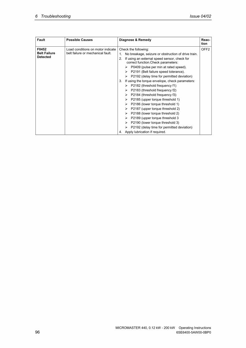
6 Troubleshooting Issue 04/02
MICROMASTER 440, 0.12 kW - 200 kW Operating Instructions96 6SE6400-5AW00-0BP0
Fault Possible Causes Diagnose & Remedy Reac-tion
F0452Belt FailureDetected
Load conditions on motor indicatebelt failure or mechanical fault.
Check the following:1. No breakage, seizure or obstruction of drive train.2. If using an external speed sensor, check for
correct function.Check parameters: P0409 (pulse per min at rated speed). P2191 (Belt failure speed tolerance). P2192 (delay time for permitted deviation)
3. If using the torque envelope, check parameters: P2182 (threshold frequency f1) P2183 (threshold frequency f2) P2184 (threshold frequency f3) P2185 (upper torque threshold 1) P2186 (lower torque threshold 1) P2187 (upper torque threshold 2) P2188 (lower torque threshold 2) P2189 (upper torque threshold 3 P2190 (lower torque threshold 3) P2192 (delay time for permitted deviation)
4. Apply lubrication if required.
OFF2

Issue 04/02 6 Troubleshooting
MICROMASTER 440, 0.12 kW - 200 kW Operating Instructions6SE6400-5AW00-0BP0 97
6.4 Alarm messagesAlarms Possible Causes Diagnose & RemedyA0501Current Limit
Motor power does notcorrespond to the inverterpower
Motor leads are too long Earth faults
Check the following:1. Motor power (P0307) must correspond to inverter power
(r0206).2. Cable length limits must not be exceeded.3. Motor cable and motor must have no short-circuits or
earth faults4. Motor parameters must match the motor in use5. Value of stator resistance (P0350) must be correct6. Motor must not be obstructed or overloaded Increase the ramp-up-time. Reduce the boost.
A0502Overvoltagelimit
Overvoltage limit is reached.This warning can occur duringramp down, if the dc-linkcontroller is disabled (P1240 = 0).
If this warning is displayed permanently, check drive inputvoltage .
A0503UnderVoltageLimit
Main supply failedMain supply (P0210) andconsequently DC-link voltage(R0026) below specified limit(P2172).
Check main supply voltage (P0210).
A0504Inverter Over-Temperature
Warning level of inverter heat-sink temperature (P0614) isexceeded, resulting in pulsefrequencyreduction and/or output frequencyreduction (depending onparametrization in (P0610)
Check the following:1. Ambient temperature must lie within specified limits2. Load conditions and duty cycle must be appropriate
A0505Inverter I2T
Warning level exceeded, currentwill be reduced if parameterized(P0610 = 1)
Check that duty cycle lies within specified limits
A0506Inverter dutycycle
Difference between heatsink andIGBT junction temperatureexceeds warning limits
Check that duty cycle and shock loads lie within specifiedlimits
A0511Motor Over-Temperature I2T
Motor overloaded Load duty cycle too high.
Independently of the kind of temperature determination check:1. P0604 motor temperature warning threshold2. P0625 motor ambient temperature3. If (P601 = 0 or 1) Check the following:
Check if name plate data are correct (if not performquick commissioning)
Accurate equivalent circuit data can be found byperforming motor identification (P1910=1).
Check if motor weight (P344) is reasonable. Changeif neccesary.
Via P626, P627, P628 the standard overtemperaturescan be changed, if the motor is nota Siemensstandard motor.
4 If (P601 = 2) Check the following: Check if temperature shown in r35 is reasonable. Check if the sensor is a KTY84 (other sensors are not
supported)A0512Motortemperaturesignal lost
Wire break to motor temperaturesensor. If a wire breakage is bedetected, temperature monitoringswitches over to monitoring withthe motor thermal model.

6 Troubleshooting Issue 04/02
MICROMASTER 440, 0.12 kW - 200 kW Operating Instructions98 6SE6400-5AW00-0BP0
Alarms Possible Causes Diagnose & RemedyA0520Rectifier Over-Temperature
Warning level of rectifier heat-sinktemperature (P) is exceeded
Check the following:1. Ambient temperature must lie within specified limits2. Load conditions and duty cycle must be appropriate3. Fan must turn when drive is running
A0521Ambient Over-Temperature
Warning level of ambienttemperature (P) is exceeded
Check the following:1. Ambient temperature must lie within specified limits2. Fan must turn when drive is running3. Fan intake air has to be without any resistance
A0522I2C read outtimeout
The cyclic access to the UCEValues and powerstacktemperatures via the i2c bus isdisturbed
A0523Output fault
One phase of output isdisconnected
Warning can be masked.
A0535BrakingResistor HotA0541Motor DataIdentificationActive
Motor data identification (P1910)selected or running
A0542Speed ControlOptimisationActive
Speed Control Optimisation(P1960) is selected or running
A0590Encoderfeedback losswarning
Signal from Encoder lost andInverter has switched tosensorless vector control
Stop inverter and then1. Check encoder fitted. If encoder not fitted, set P400 = 0
and select SLVC mode (P1300 = 20 or 22)2. Check connections between encoder and inverter3. Check encoder not faulty (select P1300 = 0, run at fixed
speed, check encoder feedback signal in P66)4. Increase encoder loss threshold in P492
A0600RTOS OverrunWarningA0700CB warning 1see CB manualfor details.
CB (communication board)specific
See CB user manual
A0701CB warning 2see CB manualfor details.
CB (communication board)specific
See CB user manual
A0702CB warning 3see CB manualfor details.
CB (communication board)specific
See CB user manual
A0703CB warning 4see CB manualfor details.
CB (communication board)specific
See CB user manual
A0704CB warning 5see CB manualfor details.
CB (communication board)specific
See CB user manual

Issue 04/02 6 Troubleshooting
MICROMASTER 440, 0.12 kW - 200 kW Operating Instructions6SE6400-5AW00-0BP0 99
Alarms Possible Causes Diagnose & RemedyA0705CB warning 6see CB manualfor details.
CB (communication board)specific
See CB user manual
A0706CB warning 7see CB manualfor details.
CB (communication board)specific
See CB user manual
A0707CB warning 8see CB manualfor details.
CB (communication board)specific
See CB user manual
A0708CB warning 9see CB manualfor details.
CB (communication board)specific
See CB user manual
A0709CB warning 10see CB manualfor details.
CB (communication board)specific
See CB user manual
A0710CBcommunicationerror
Communication with CB(communication board) is lost
Check CB hardware
A0711CBconfigurationerror
CB (communication board)reports a configuration error.
Check CB parameters
A0910Vdc-maxcontroller de-activated
Vdc max controller has been de-activated, since controller is notcapable of keeping DC-linkvoltage (r0026) within limits(P2172). Occurs if main supply voltage
(P0210) is permanently toohigh.
Occurs if motor is driven byan active load, causing motorto goes into regenerativemode.
Occurs at very high loadinertias, when ramping down.
Check the following:1. Input voltage (P0210) must lie within range.2. Load must be match.
A0911Vdc-maxcontroller active
Vdc max controller is active; soramp-down times will beincreased automatically to keepDC-link voltage (r0026) withinlimits (P2172).
A0912Vdc-mincontroller active
Vdc min controller will beactivated if DC-link voltage(r0026) falls below minimum level(P2172). The kinetic energy of the
motor is used to buffer theDC-link voltage, thus causingdeceleration of the drive!
So short mains failures do notnecessarily lead to anundervoltage trip.

6 Troubleshooting Issue 04/02
MICROMASTER 440, 0.12 kW - 200 kW Operating Instructions100 6SE6400-5AW00-0BP0
Alarms Possible Causes Diagnose & RemedyA0920ADC parametersnot set properly.
ADC parameters should not beset to identical values, since thiswould produce illogical results. Index 0: Parameter settings
for output identical Index 1: Parameter settings
for input identical Index 2: Parameter settings
for input do not correspond toADC type
A0921DAC parametersnot set properly.
DAC parameters should not beset to identical values, since thiswould produce illogical results. Index 0: Parameter settings
for output identical Index 1: Parameter settings
for input identical Index 2: Parameter settings
for output do not correspondto DAC type
A0922No load appliedto inverter
No Load is applied to the inverter.As a result, some functions maynot work as under normal loadconditions.
A0923Both JOG Leftand JOG Rightare requested
Both JOG right and JOG left(P1055/P1056) have beenrequested. This freezes the RFGoutput frequency at its currentvalue.
A0952Belt FailureDetected
Load conditions on motor indicatebelt failure or mechanical fault.
Apply lubrication if required.Check the following:1. No breakage, seizure or obstruction of drive train.2. If using an external speed sensor, check for correct
function.Check parameters: P0409 (pulse per min at rated speed). P2191 (Belt failure speed tolerance). P2192 (delay time for permitted deviation)
3. If using the torque envelope, check parameters: P2182 (threshold frequency f1) P2183 (threshold frequency f2) P2184 (threshold frequency f3) P2185 (upper torque threshold 1) P2186 (lower torque threshold 1) P2187 (upper torque threshold 2) P2188 (lower torque threshold 2) P2189 (upper torque threshold 3) P2190 (lower torque threshold 3) P2192 (delay time for permitted deviation)
4. Apply lubrication if required.A0936PID AutouningActive
PID Autotuning (P2350) selectedor running

Issue 04/02 7 MICROMASTER 440 specifications
MICROMASTER 440, 0.12 kW - 200 kW Operating Instructions6SE6400-5AW00-0BP0 101
7 MICROMASTER 440 specifications
This Chapter contains: Table 7.1 contains the general technical specifications for the
MICROMASTER 440 inverter Table 7-2 contains terminal tightening torques Table 7-3 includes various tables of specific technical data for individual
MICROMASTER 440 inverters
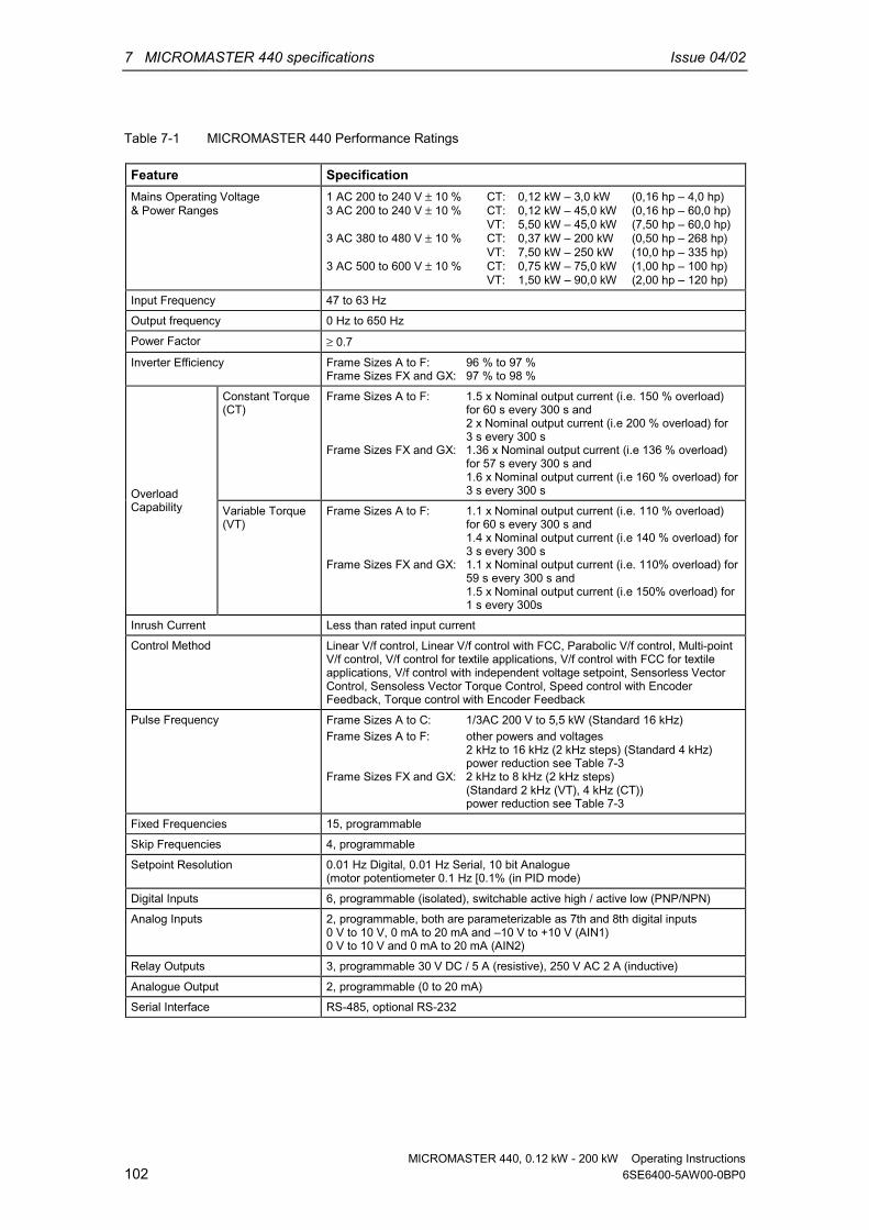
7 MICROMASTER 440 specifications Issue 04/02
MICROMASTER 440, 0.12 kW - 200 kW Operating Instructions102 6SE6400-5AW00-0BP0
Table 7-1 MICROMASTER 440 Performance Ratings
Feature SpecificationMains Operating Voltage& Power Ranges
1 AC 200 to 240 V ± 10 % CT: 0,12 kW – 3,0 kW (0,16 hp – 4,0 hp)3 AC 200 to 240 V ± 10 % CT: 0,12 kW – 45,0 kW (0,16 hp – 60,0 hp)
VT: 5,50 kW – 45,0 kW (7,50 hp – 60,0 hp)3 AC 380 to 480 V ± 10 % CT: 0,37 kW – 200 kW (0,50 hp – 268 hp)
VT: 7,50 kW – 250 kW (10,0 hp – 335 hp)3 AC 500 to 600 V ± 10 % CT: 0,75 kW – 75,0 kW (1,00 hp – 100 hp)
VT: 1,50 kW – 90,0 kW (2,00 hp – 120 hp)
Input Frequency 47 to 63 Hz
Output frequency 0 Hz to 650 Hz
Power Factor ≥ 0.7
Inverter Efficiency Frame Sizes A to F: 96 % to 97 %Frame Sizes FX and GX: 97 % to 98 %
Constant Torque(CT)
Frame Sizes A to F: 1.5 x Nominal output current (i.e. 150 % overload)for 60 s every 300 s and2 x Nominal output current (i.e 200 % overload) for3 s every 300 s
Frame Sizes FX and GX: 1.36 x Nominal output current (i.e 136 % overload)for 57 s every 300 s and1.6 x Nominal output current (i.e 160 % overload) for3 s every 300 sOverload
Capability Variable Torque(VT)
Frame Sizes A to F: 1.1 x Nominal output current (i.e. 110 % overload)for 60 s every 300 s and1.4 x Nominal output current (i.e 140 % overload) for3 s every 300 s
Frame Sizes FX and GX: 1.1 x Nominal output current (i.e. 110% overload) for59 s every 300 s and1.5 x Nominal output current (i.e 150% overload) for1 s every 300s
Inrush Current Less than rated input current
Control Method Linear V/f control, Linear V/f control with FCC, Parabolic V/f control, Multi-pointV/f control, V/f control for textile applications, V/f control with FCC for textileapplications, V/f control with independent voltage setpoint, Sensorless VectorControl, Sensoless Vector Torque Control, Speed control with EncoderFeedback, Torque control with Encoder Feedback
Pulse Frequency Frame Sizes A to C: 1/3AC 200 V to 5,5 kW (Standard 16 kHz)Frame Sizes A to F: other powers and voltages
2 kHz to 16 kHz (2 kHz steps) (Standard 4 kHz)power reduction see Table 7-3
Frame Sizes FX and GX: 2 kHz to 8 kHz (2 kHz steps)(Standard 2 kHz (VT), 4 kHz (CT))power reduction see Table 7-3
Fixed Frequencies 15, programmable
Skip Frequencies 4, programmable
Setpoint Resolution 0.01 Hz Digital, 0.01 Hz Serial, 10 bit Analogue(motor potentiometer 0.1 Hz [0.1% (in PID mode)
Digital Inputs 6, programmable (isolated), switchable active high / active low (PNP/NPN)
Analog Inputs 2, programmable, both are parameterizable as 7th and 8th digital inputs0 V to 10 V, 0 mA to 20 mA and –10 V to +10 V (AIN1)0 V to 10 V and 0 mA to 20 mA (AIN2)
Relay Outputs 3, programmable 30 V DC / 5 A (resistive), 250 V AC 2 A (inductive)
Analogue Output 2, programmable (0 to 20 mA)
Serial Interface RS-485, optional RS-232

Issue 04/02 7 MICROMASTER 440 specifications
MICROMASTER 440, 0.12 kW - 200 kW Operating Instructions6SE6400-5AW00-0BP0 103
Electromagnetic Compatibility Frame Sizes A to C: optional class A or B filters available according toEN55011
Frame Sizes A to F: inverter with integrated class A filter availableFrame Sizes FX and GX: With EMI filter (available as an option) the limiting
values of the EN 55011, Class A are fulfilled forconducted emission.(line commutating choke required)
Braking DC braking, compound brakingDynamic braking Frame Sizes A to F with integrated chopper
Frame Sizes FX and GX with external chopper
Protection Level IP20
Temperature range Frame Sizes A to F: -10 °C to +50 °C (14 °F to 122 °F) (CT)-10 °C to +40 °C (14 °F to 104 °F) (VT)with power reduction see Figure 2-2
Frame Sizes FX and GX: 0 °C to +40 °C (32 °F to 104 °F), to 55 °C (131 °F)with power reduction see Figure 2-2
Storage Temperature -40 °C to +70 °C (-40 °F to 158 °F)
Humidity < 95 % RH – non-condensing
Operational Altitudes Frame Sizes A to F: Up to 1000 m above sea level without deratingFrame Sizes FX and GX: Up to 2000 m above sea level without derating
Protection Features Undervoltage , Overvoltage, Overload, Ground Faults, Short circuit, StallPrevention, Motor Blocking Protection, Motor Overtemperature, InverterOvertemperature, Parameter Interlock
Standards Frame Sizes A to F: UL, cUL, CE, C-tickFrame Sizes FX and GX: UL (in preparation), cUL (in preparation), CE
CE Marked Conformity with EC Low Voltage Directive 73/23/EECand filtered versions also Electromagnetic Compatibility Directive 89/336/EEC
Table 7-2 Tightening torques for power terminals
Frame Sizes A to FFrame Size A B C D E F
[Nm] 1,1 1,5 2,25 10 (max) 10 (max) 50TighteningTorque [lbf.in] 10 13,3 20 87 (max) 87 (max) 435
Frame Sizes FX and GXFrame Size FX GX
[Nm] 50 50Tightening Torque
[lbf.in] 435 435
Pipe cable lug acc. to DIN 46235 mm 10 10
[mm2] 1 x 185 or 2 x 120 2 x 240Max. wire cross-section
[AWG] and [kcmil] 1 x 350 or 2 x 4/0 2 x 400

7 MICROMASTER 440 specifications Issue 04/02
MICROMASTER 440, 0.12 kW - 200 kW Operating Instructions104 6SE6400-5AW00-0BP0
Table 7-3 Current reduction depending on pulse frequency
Output current in A with a switching frequency of;Mains voltage Power (CT)[kW] 4 kHz 6 kHz 8 kHz 10 kHz 12 kHz 14 kHz 16 kHz
0.12 to 5.5 Factory setting 16 kHz – no derating necessary7.5 28.0 26.6 25.2 22.4 19.6 16.8 14.011 42.0 37.8 33.6 29.4 25.2 21.0 16.815 54.0 48.6 43.2 37.8 32.4 27.0 21.6
18.5 68.0 64.6 61.2 54.4 47.6 40.8 34.022 80.0 72.0 64.0 56.0 48.0 40.0 32.030 104.0 91.0 78.0 70.2 62.4 57.2 52.037 130.0 113.8 97.5 87.8 78.0 71.5 65.0
1/3 AC 200 V
45 154.0 134.8 115.5 104.0 92.4 84.7 77.00.37 1.3 1.3 1.3 1.3 1.3 1.2 1.00.55 1.7 1.7 1.7 1.6 1.5 1.4 1.20.75 2.2 2.2 2.2 2.0 1.8 1.5 1.31.1 3.1 2.9 2.8 2.5 2.2 1.9 1.61.5 4.1 3.7 3.3 2.9 2.5 2.1 1.62.2 5.9 5.6 5.3 4.7 4.1 3.5 3.03.0 7.7 6.9 6.2 5.4 4.6 3.9 3.14.0 10.2 9.2 8.2 7.1 6.1 5.1 4.15.5 13.2 11.9 10.6 9.2 7.9 6.6 5.37.5 19.0 18.1 17.1 15.2 13.3 11.4 9.5
11.0 26.0 23.4 20.8 18.2 15.6 13.0 10.415.0 32.0 30.4 28.8 25.6 22.4 19.2 16.018.5 38.0 34.2 30.4 26.6 22.8 19.0 15.2
22 45.0 40.5 36.0 31.5 27.0 22.5 18.030 62.0 58.9 55.8 49.6 43.4 37.2 31.037 75.0 67.5 60.0 52.5 45.0 37.5 30.045 90.0 76.5 63.0 51.8 40.5 33.8 27.055 110.0 93.5 77.0 63.3 49.5 41.3 33.075 145.0 112.4 79.8 68.9 58.0 50.8 43.590 178.0 131.5 101.1 – – – –
110 205.0 151.4 116.5 – – – –132 250.0 184.7 142.1 – – – –160 302.0 223.1 171.6 – – – –
3 AC 400 V
200 370.0 273.3 210.2 – – – –0.75 1.4 1.2 1.0 0.8 0.7 0.6 0.61.5 2.7 2.2 1.6 1.4 1.1 0.9 0.82.2 3.9 2.9 2.0 1.6 1.2 1.0 0.84.0 6.1 4.6 3.1 2.4 1.8 1.5 1.25.5 9.0 6.8 4.5 3.6 2.7 2.3 1.87.5 11.0 8.8 6.6 5.5 4.4 3.9 3.3
11.0 17.0 12.8 8.5 6.8 5.1 4.3 3.415.0 22.0 17.6 13.2 11.0 8.8 7.7 6.618.5 27.0 20.3 13.5 10.8 8.1 6.8 5.4
22 32.0 24.0 16.0 12.8 9.6 8.0 6.430 41.0 32.8 24.6 20.5 16.4 14.4 12.337 52.0 39.0 26.0 20.8 15.6 13.0 10.445 62.0 52.7 43.4 40.3 37.2 32.6 27.955 77.0 67.4 57.8 52.0 46.2 42.4 38.5
3 AC 500 V
75 99.0 84.2 69.3 64.4 59.4 52.0 44.6

Issue 04/02 7 MICROMASTER 440 specifications
MICROMASTER 440, 0.12 kW - 200 kW Operating Instructions6SE6400-5AW00-0BP0 105
Table 7-4 MICROMASTER 440 Specifications
In order to have a UL compliant installation fuses from the SITOR range with theappropriate current rating must be used.
Input voltage range 1 AC 200 V – 240 V, ± 10 % (with built in Class A Filter)Order No. 6SE6440- 2AB11
-2AA12AB12-5AA1
2AB13-7AA1
2AB15-5AA1
2AB17-5AA1
2AB21-1BA1
2AB21-5BA1
2AB22-2BA1
2AB23-0CA1
[kW] 0.12 0.25 0.37 0.55 0.75 1.1 1.5 2.2 3.0Motor Output Rating [hp] 0.16 0.33 0.5 0.75 1.0 1.5 2.0 3.0 4.0Output Power [kVA] 0.4 0.7 1.0 1.3 1.7 2.4 3.2 4.6 6.0Output Current Max. [A] 0.9 1.7 2.3 3.0 3.9 5.5 7.4 10.4 13.6Input Current [A] 1.4 2.7 3.7 5.0 6.6 9.6 13.0 17.6 23.7
10 10 10 16 16 20 20 25 32Recommended Fuse [A]3NA3803 3NA3803 3NA3803 3NA3805 3NA3805 3NA3807 3NA3807 3NA3810 3NA3812
[A]Fuses for ULspecified * * * * * * * * *
[mm2] 1.0 1.0 1.0 1.0 1.0 1.0 1.5 2.5 4.0Input Cable Min. [awg] 17 17 17 17 17 17 15 13 11[mm2] 2.5 2.5 2.5 2.5 2.5 6.0 6.0 6.0 10.0Input Cable Max. [awg] 13 13 13 13 13 9 9 9 7[mm2] 1.0 1.0 1.0 1.0 1.0 1.0 1.0 1.0 1.5Output Cable Min. [awg] 17 17 17 17 17 17 17 17 15[mm2] 2.5 2.5 2.5 2.5 2.5 6.0 6.0 6.0 10.0Output Cable Max. [awg] 13 13 13 13 13 9 9 9 7[kg] 1.3 1.3 1.3 1.3 1.3 3.4 3.4 3.4 5.7Weight [lbs] 2.9 2.9 2.9 2.9 2.9 7.5 7.5 7.5 12.5
B [mm] 73.0 73.0 73.0 73.0 73.0 149.0 149.0 149.0 185.0H [mm] 173.0 173.0 173.0 173.0 173.0 202.0 202.0 202.0 245.0T [mm] 149.0 149.0 149.0 149.0 149.0 172.0 172.0 172.0 195.0B [Inches] 2.87 2.87 2.87 2.87 2.87 5.87 5.87 5.87 7.28H [Inches] 6.81 6.81 6.81 6.81 6.81 7.95 7.95 7.95 9.65
Dimensions
T [Inches] 5.87 5.87 5.87 5.87 5.87 6.77 6.77 6.77 7.68
* UL listed fuses such as Class NON from Bussmann are required for use in America

7 MICROMASTER 440 specifications Issue 04/02
MICROMASTER 440, 0.12 kW - 200 kW Operating Instructions106 6SE6400-5AW00-0BP0
Input voltage range 3 AC 200 V – 240 V, ± 10 % (with built in Class A Filter)Order No. 6SE6440- 2AC23-
0CA12AC24-0CA1
2AC25-5CA1
[kW] 3.0 4.0 5.5Motor Output Rating [hp] 4.0 5.0 7.5Output Power [kVA] 6.0 7.7 9.6CT-Output Cur. Max. [A] 13.6 17.5 22.0CT Input Current [A] 10.5 13.1 17.5VT Input Current [A] 10.5 17.6 26.5VT-Output Cur. Max. [A] 13.6 22.0 28.0
20 25 35Recommended Fuse [A]3NA3807 3NA3810 3NA3814
[A]Fuses for UL specified* * *
[mm2] 1.0 2.5 4.0Input Cable Min. [awg] 17.0 13.0 11.0[mm2] 10.0 10.0 10.0Input Cable Max. [awg] 7.0 7.0 7.0[mm2] 1.5 4.0 4.0Output Cable Min. [awg] 15.0 11.0 11.0[mm2] 10.0 10.0 10.0Output Cable Max. [awg] 7.0 7.0 7.0[kg] 5.7 5.7 5.7Weight [lbs] 12.5 12.5 12.5
B [mm] 185.0 185.0 185.0H [mm] 245.0 245.0 245.0T [mm] 195.0 195.0 195.0B [Inches] 7.28 7.28 7.28H [Inches] 9.65 9.65 9.65
Dimensions
T [Inches] 7.68 7.68 7.68
* UL listed fuses such as Class NON from Bussmann are required for use in America

Issue 04/02 7 MICROMASTER 440 specifications
MICROMASTER 440, 0.12 kW - 200 kW Operating Instructions6SE6400-5AW00-0BP0 107
Input voltage range 1 AC 3 AC 200 V – 240 V, ± 10 % (Unfiltered)Order No. 6SE6440- 2UC11
-2AA12UC12-5AA1
2UC13-7AA1
2UC15-5AA1
2UC17-5AA1
2UC21-1BA1
2UC21-5BA1
2UC22-2BA1
2UC23-0CA1
[kW] 0.12 0.25 0.37 0.55 0.75 1.1 1.5 2.2 3.0Motor Output Rating [hp] 0.16 0.33 0.5 0.75 1.0 1.5 2.0 3.0 4.0Output Power [kVA] 0.4 0.7 1.0 1.3 1.7 2.4 3.2 4.6 6.0Output Current Max. [A] 0.9 1.7 2.3 3.0 3.9 5.5 7.4 10.4 13.6Input Current, 3 AC [A] 0.6 1.1 1.6 2.1 2.9 4.1 5.6 7.6 10.5Input Current, 1 AC [A] 1.4 2.7 3.7 5.0 6.6 9.6 13.0 17.6 23.7
10 10 10 16 16 20 20 25 32Recommended Fuse [A]3NA3803 3NA3803 3NA3803 3NA3805 3NA3805 3NA3807 3NA3807 3NA3810 3NA3812
[A]Fuses for ULspecified * * * * * * * * *
[mm2] 1.0 1.0 1.0 1.0 1.0 1.0 1.5 2.5 4.0Input Cable Min. [awg] 17 17 17 17 17 17 15 13 11[mm2] 2.5 2.5 2.5 2.5 2.5 6.0 6.0 6.0 10.0Input Cable Max. [awg] 13 13 13 13 13 9 9 9 7[mm2] 1.0 1.0 1.0 1.0 1.0 1.0 1.0 1.0 1.5Output Cable Min. [awg] 17 17 17 17 17 17 17 17 15[mm2] 2.5 2.5 2.5 2.5 2.5 6.0 6.0 6.0 10.0Output Cable Max. [awg] 13 13 13 13 13 9 9 9 7[kg] 1.3 1.3 1.3 1.3 1.3 3.3 3.3 3.3 5.5Weight [lbs] 2.9 2.9 2.9 2.9 2.9 7.3 7.3 7.3 12.1
B [mm] 73.0 73.0 73.0 73.0 73.0 149.0 149.0 149.0 185.0H [mm] 173.0 173.0 173.0 173.0 173.0 202.0 202.0 202.0 245.0T [mm] 149.0 149.0 149.0 149.0 149.0 172.0 172.0 172.0 195.0B [Inches] 2.87 2.87 2.87 2.87 2.87 5.87 5.87 5.87 7.28H [Inches] 6.81 6.81 6.81 6.81 6.81 7.95 7.95 7.95 9.65
Dimensions
T [Inches] 5.87 5.87 5.87 5.87 5.87 6.77 6.77 6.77 7.68
* UL listed fuses such as Class NON from Bussmann are required for use in America
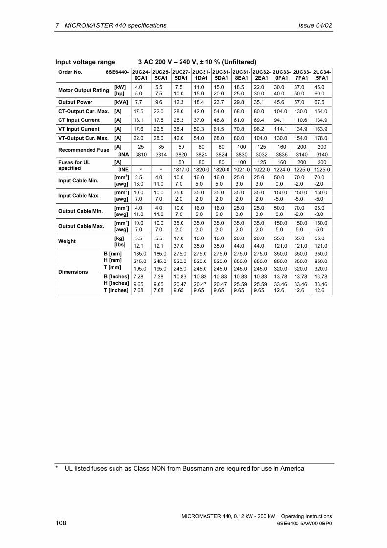
7 MICROMASTER 440 specifications Issue 04/02
MICROMASTER 440, 0.12 kW - 200 kW Operating Instructions108 6SE6400-5AW00-0BP0
Input voltage range 3 AC 200 V – 240 V, ± 10 % (Unfiltered)Order No. 6SE6440- 2UC24-
0CA12UC25-5CA1
2UC27-5DA1
2UC31-1DA1
2UC31-5DA1
2UC31-8EA1
2UC32-2EA1
2UC33-0FA1
2UC33-7FA1
2UC34-5FA1
[kW] 4.0 5.5 7.5 11.0 15.0 18.5 22.0 30.0 37.0 45.0Motor Output Rating [hp] 5.0 7.5 10.0 15.0 20.0 25.0 30.0 40.0 50.0 60.0Output Power [kVA] 7.7 9.6 12.3 18.4 23.7 29.8 35.1 45.6 57.0 67.5CT-Output Cur. Max. [A] 17.5 22.0 28.0 42.0 54.0 68.0 80.0 104.0 130.0 154.0CT Input Current [A] 13.1 17.5 25.3 37.0 48.8 61.0 69.4 94.1 110.6 134.9VT Input Current [A] 17.6 26.5 38.4 50.3 61.5 70.8 96.2 114.1 134.9 163.9VT-Output Cur. Max. [A] 22.0 28.0 42.0 54.0 68.0 80.0 104.0 130.0 154.0 178.0
[A] 25 35 50 80 80 100 125 160 200 200Recommended Fuse3NA 3810 3814 3820 3824 3824 3830 3032 3836 3140 3140
[A] 50 80 80 100 125 160 200 200Fuses for ULspecified 3NE * * 1817-0 1820-0 1820-0 1021-0 1022-0 1224-0 1225-0 1225-0
[mm2] 2.5 4.0 10.0 16.0 16.0 25.0 25.0 50.0 70.0 70.0Input Cable Min. [awg] 13.0 11.0 7.0 5.0 5.0 3.0 3.0 0.0 -2.0 -2.0[mm2] 10.0 10.0 35.0 35.0 35.0 35.0 35.0 150.0 150.0 150.0Input Cable Max. [awg] 7.0 7.0 2.0 2.0 2.0 2.0 2.0 -5.0 -5.0 -5.0[mm2] 4.0 4.0 10.0 16.0 16.0 25.0 25.0 50.0 70.0 95.0Output Cable Min. [awg] 11.0 11.0 7.0 5.0 5.0 3.0 3.0 0.0 -2.0 -3.0[mm2] 10.0 10.0 35.0 35.0 35.0 35.0 35.0 150.0 150.0 150.0Output Cable Max. [awg] 7.0 7.0 2.0 2.0 2.0 2.0 2.0 -5.0 -5.0 -5.0[kg] 5.5 5.5 17.0 16.0 16.0 20.0 20.0 55.0 55.0 55.0Weight [lbs] 12.1 12.1 37.0 35.0 35.0 44.0 44.0 121.0 121.0 121.0
B [mm] 185.0 185.0 275.0 275.0 275.0 275.0 275.0 350.0 350.0 350.0H [mm] 245.0 245.0 520.0 520.0 520.0 650.0 650.0 850.0 850.0 850.0T [mm] 195.0 195.0 245.0 245.0 245.0 245.0 245.0 320.0 320.0 320.0B [Inches] 7.28 7.28 10.83 10.83 10.83 10.83 10.83 13.78 13.78 13.78H [Inches] 9.65 9.65 20.47 20.47 20.47 25.59 25.59 33.46 33.46 33.46
Dimensions
T [Inches] 7.68 7.68 9.65 9.65 9.65 9.65 9.65 12.6 12.6 12.6
* UL listed fuses such as Class NON from Bussmann are required for use in America
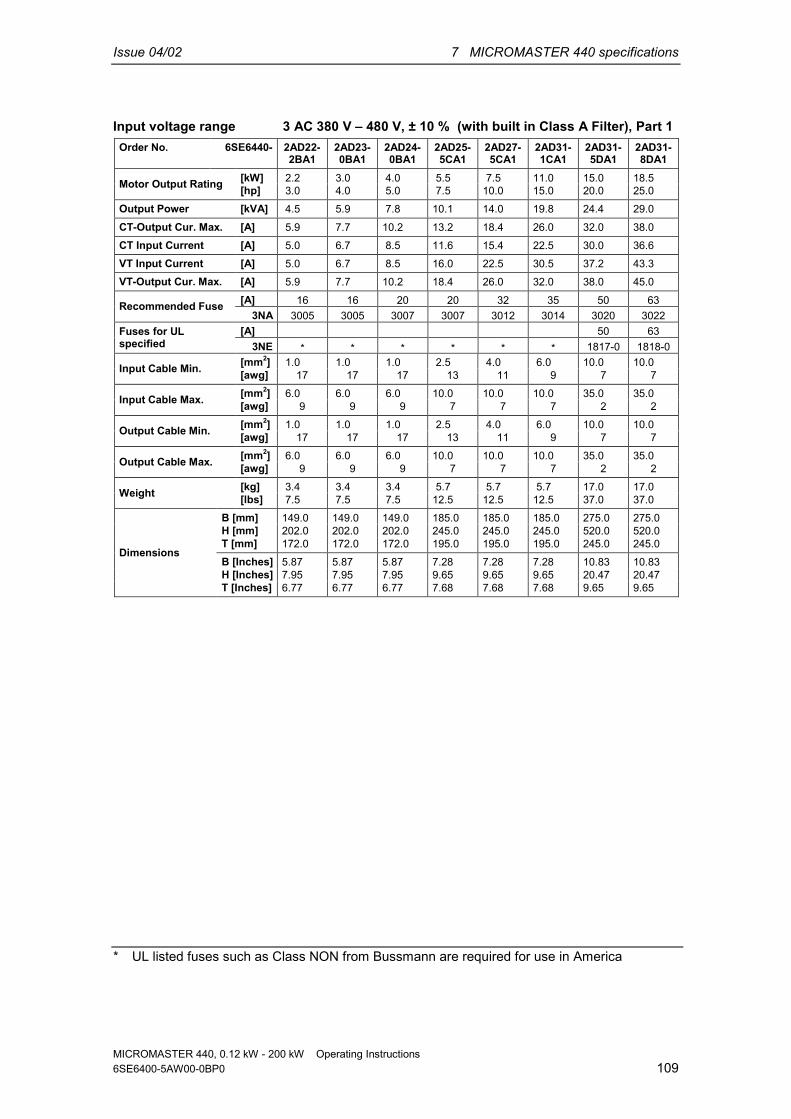
Issue 04/02 7 MICROMASTER 440 specifications
MICROMASTER 440, 0.12 kW - 200 kW Operating Instructions6SE6400-5AW00-0BP0 109
Input voltage range 3 AC 380 V – 480 V, ± 10 % (with built in Class A Filter), Part 1Order No. 6SE6440- 2AD22-
2BA12AD23-0BA1
2AD24-0BA1
2AD25-5CA1
2AD27-5CA1
2AD31-1CA1
2AD31-5DA1
2AD31-8DA1
[kW] 2.2 3.0 4.0 5.5 7.5 11.0 15.0 18.5Motor Output Rating [hp] 3.0 4.0 5.0 7.5 10.0 15.0 20.0 25.0Output Power [kVA] 4.5 5.9 7.8 10.1 14.0 19.8 24.4 29.0CT-Output Cur. Max. [A] 5.9 7.7 10.2 13.2 18.4 26.0 32.0 38.0CT Input Current [A] 5.0 6.7 8.5 11.6 15.4 22.5 30.0 36.6VT Input Current [A] 5.0 6.7 8.5 16.0 22.5 30.5 37.2 43.3VT-Output Cur. Max. [A] 5.9 7.7 10.2 18.4 26.0 32.0 38.0 45.0
[A] 16 16 20 20 32 35 50 63Recommended Fuse3NA 3005 3005 3007 3007 3012 3014 3020 3022
[A] 50 63Fuses for ULspecified 3NE * * * * * * 1817-0 1818-0
[mm2] 1.0 1.0 1.0 2.5 4.0 6.0 10.0 10.0Input Cable Min. [awg] 17 17 17 13 11 9 7 7[mm2] 6.0 6.0 6.0 10.0 10.0 10.0 35.0 35.0Input Cable Max. [awg] 9 9 9 7 7 7 2 2[mm2] 1.0 1.0 1.0 2.5 4.0 6.0 10.0 10.0Output Cable Min. [awg] 17 17 17 13 11 9 7 7[mm2] 6.0 6.0 6.0 10.0 10.0 10.0 35.0 35.0Output Cable Max. [awg] 9 9 9 7 7 7 2 2[kg] 3.4 3.4 3.4 5.7 5.7 5.7 17.0 17.0Weight [lbs] 7.5 7.5 7.5 12.5 12.5 12.5 37.0 37.0
B [mm] 149.0 149.0 149.0 185.0 185.0 185.0 275.0 275.0H [mm] 202.0 202.0 202.0 245.0 245.0 245.0 520.0 520.0T [mm] 172.0 172.0 172.0 195.0 195.0 195.0 245.0 245.0B [Inches] 5.87 5.87 5.87 7.28 7.28 7.28 10.83 10.83H [Inches] 7.95 7.95 7.95 9.65 9.65 9.65 20.47 20.47
Dimensions
T [Inches] 6.77 6.77 6.77 7.68 7.68 7.68 9.65 9.65
* UL listed fuses such as Class NON from Bussmann are required for use in America

7 MICROMASTER 440 specifications Issue 04/02
MICROMASTER 440, 0.12 kW - 200 kW Operating Instructions110 6SE6400-5AW00-0BP0
Input voltage range 3 AC 380 V – 480 V, ± 10 % (with built in Class A Filter), Part 2Order No. 6SE6440- 2AD32-
2DA12AD33-0EA1
2AD33-7EA1
2AD34-5FA1
2AD35-5FA1
2AD37-5FA1
[kW] 22.0 30.0 37.0 45.0 55.0 75.0Motor Output Rating [hp] 30.0 40.0 50.0 60.0 75.0 100.0Output Power [kVA] 34.3 47.3 57.2 68.6 83.8 110.5CT-Output Cur. Max. [A] 45.0 62.0 75.0 90.0 110.0 145.0CT Input Current [A] 43.1 58.7 71.2 85.6 103.6 138.5VT Input Current [A] 59.3 71.7 86.6 103.6 138.5 168.5VT-Output Cur. Max. [A] 62.0 75.0 90.0 110.0 145.0 178.0
[A] 80 100 125 160 200 200Recommended Fuse3NA 3024 3030 3032 3036 3140 3140
[A] 80 100 125 160 200 200Fuses for ULspecified 3NE 1820-0 1021-0 1022-0 1224-0 1225-0 1225-0
[mm2] 16.0 25.0 25.0 35.0 70.0 70.0Input Cable Min. [awg] 5 3 3 2 -2 -2[mm2] 35.0 35.0 35.0 150.0 150.0 150.0Input Cable Max. [awg] 2 2 2 -5 -5 -5[mm2] 16.0 25.0 25.0 50.0 70.0 95.0Output Cable Min. [awg] 5 3 3 0 -2 -3[mm2] 35.0 35.0 35.0 150.0 150.0 150.0Output Cable Max. [awg] 2 2 2 -5 -5 -5[kg] 17.0 22.0 22.0 75.0 75.0 75.0Weight [lbs] 37.0 48.0 48.0 165.0 165.0 165.0
B [mm] 275.0 275.0 275.0 350.0 350.0 350.0H [mm] 520.0 650.0 650.0 1150.0 1150.0 1150.0T [mm] 245.0 245.0 245.0 320.0 320.0 320.0B [Inches] 10.83 10.83 10.83 13.78 13.78 13.78H [Inches] 20.47 25.59 25.59 45.28 45.28 45.28
Dimensions
T [Inches] 9.65 9.65 9.65 12.6 12.6 12.6

Issue 04/02 7 MICROMASTER 440 specifications
MICROMASTER 440, 0.12 kW - 200 kW Operating Instructions6SE6400-5AW00-0BP0 111
Input voltage range 3 AC 380 V – 480 V, ± 10 % (Unfiltered), Part 1Order No. 6SE6440- 2UD13-
7AA12UD15-5AA1
2UD17-5AA1
2UD21-1AA1
2UD21-5AA1
2UD22-2BA1
2UD23-0BA1
2UD24-0BA1
2UD25-5CA1
2UD27-5CA1
[kW] 0.37 0.55 0.75 1.1 1.5 2.2 3.0 4.0 5.5 7.5Motor Output Rating [hp] 0.5 0.75 1.0 1.5 2.0 3.0 4.0 5.0 7.5 10.0Output Power [kVA] 0.9 1.2 1.6 2.3 3.0 4.5 5.9 7.8 10.1 14.0CT-Output Cur. Max. [A] 1.2 1.6 2.1 3.0 4.0 5.9 7.7 10.2 13.2 18.4CT Input Current [A] 1.1 1.4 1.9 2.8 3.9 5.0 6.7 8.5 11.6 15.4VT Input Current [A] 1.1 1.4 1.9 2.8 3.9 5.0 6.7 8.5 16.0 22.5VT-Output Cur. Max. [A] 1.2 1.6 2.1 3.0 4.0 5.9 7.7 10.2 18.4 26.0
10 10 10 10 10 16 16 20 20 32Recommended Fuse [A]3NA3003 3NA3003 3NA3003 3NA3003 3NA3003 3NA3005 3NA3005 3NA3007 3NA3007 3NA3012
[A]Fuses for ULspecified * * * * * * * * * *
[mm2] 1.0 1.0 1.0 1.0 1.0 1.0 1.0 1.0 2.5 4.0Input Cable Min. [awg] 17 17 17 17 17 17 17 17 13 11[mm2] 2.5 2.5 2.5 2.5 2.5 6.0 6.0 6.0 10.0 10.0Input Cable Max. [awg] 13 13 13 13 13 9 9 9 7 7[mm2] 1.0 1.0 1.0 1.0 1.0 1.0 1.0 1.0 2.5 4.0Output Cable Min. [awg] 17 17 17 17 17 17 17 17 13 11[mm2] 2.5 2.5 2.5 2.5 2.5 6.0 6.0 6.0 10.0 10.0Output Cable Max. [awg] 13 13 13 13 13 9 9 9 7 7[kg] 1.3 1.3 1.3 1.3 1.3 3.3 3.3 3.3 5.5 5.5Weight [lbs] 2.9 2.9 2.9 2.9 2.9 7.3 7.3 7.3 12.1 12.1
B [mm] 73.0 73.0 73.0 73.0 73.0 149.0 149.0 149.0 185.0 185.0H [mm] 173.0 173.0 173.0 173.0 173.0 202.0 202.0 202.0 245.0 245.0T [mm] 149.0 149.0 149.0 149.0 149.0 172.0 172.0 172.0 195.0 195.0B [Inches] 2.87 2.87 2.87 2.87 2.87 5.87 5.87 5.87 7.28 7.28H [Inches] 6.81 6.81 6.81 6.81 6.81 7.95 7.95 7.95 9.65 9.65
Dimensions
T [Inches] 5.87 5.87 5.87 5.87 5.87 6.77 6.77 6.77 7.68 7.68
* UL listed fuses such as Class NON from Bussmann are required for use in America

7 MICROMASTER 440 specifications Issue 04/02
MICROMASTER 440, 0.12 kW - 200 kW Operating Instructions112 6SE6400-5AW00-0BP0
Input voltage range 3 AC 380 V – 480 V, ± 10 % (Unfiltered), Part 2Order No. 6SE6440- 2UD31
-1CA12UD31-5DA1
2UD31-8DA1
2UD32-2DA1
2UD33-0EA1
2UD33-7EA1
2UD34-5FA1
2UD35-5FA1
2UD37-5FA1
[kW] 11.0 15.0 18.5 22.0 30.0 37.0 45.0 55.0 75.0Motor Output Rating [hp] 15.0 20.0 25.0 30.0 40.0 50.0 60.0 75.0 100.0Output Power [kVA] 19.8 24.4 29.0 34.3 47.3 57.2 68.6 83.8 110.5CT-Output Cur. Max. [A] 26.0 32.0 38.0 45.0 62.0 75.0 90.0 110.0 145.0CT Input Current [A] 22.5 30.0 36.6 43.1 58.7 71.2 85.6 103.6 138.5VT Input Current [A] 30.5 37.2 43.3 59.3 71.7 86.6 103.6 138.5 168.5VT-Output Cur. Max. [A] 32.0 38.0 45.0 62.0 75.0 90.0 110.0 145.0 178.0
[A] 35 50 63 80 100 125 160 200 200Recommended Fuse3NA 3014 3020 3022 3024 3030 3032 3036 3140 3140
[A] 50 63 80 100 125 160 200 200Fuses for ULspecified 3NE * 1817-0 1818-0 1820-0 1021-0 1022-0 1224-0 1225-0 1225-0
[mm2] 6.0 10.0 10.0 16.0 25.0 25.0 35.0 70.0 70.0Input Cable Min. [awg] 9 7 7 5 3 3 2 -2 -2[mm2] 10.0 35.0 35.0 35.0 35.0 35.0 150.0 150.0 150.0Input Cable Max. [awg] 7 2 2 2 2 2 -5 -5 -5[mm2] 6.0 10.0 10.0 16.0 25.0 25.0 35.0 70.0 95.0Output Cable Min. [awg] 9 7 7 5 3 3 2 -2 -3[mm2] 10.0 35.0 35.0 35.0 35.0 35.0 150.0 150.0 150.0Output Cable Max. [awg] 7 2 2 2 2 2 -5 -5 -5[kg] 5.5 16.0 16.0 16.0 20.0 20.0 56.0 56.0 56.0Weight [lbs] 12.1 35.0 35.0 35.0 44.0 44.0 123.0 123.0 123.0
B [mm] 185.0 275.0 275.0 275.0 275.0 275.0 350.0 350.0 350.0H [mm] 245.0 520.0 520.0 520.0 650.0 650.0 850.0 850.0 850.0T [mm] 195.0 245.0 245.0 245.0 245.0 245.0 320.0 320.0 320.0B [Inches] 7.28 10.83 10.83 10.83 10.83 10.83 13.78 13.78 13.78H [Inches] 9.65 20.47 20.47 20.47 25.59 25.59 33.46 33.46 33.46
Dimensions
T [Inches] 7.68 9.65 9.65 9.65 9.65 9.65 12.6 12.6 12.6
* UL listed fuses such as Class NON from Bussmann are required for use in America

Issue 04/02 7 MICROMASTER 440 specifications
MICROMASTER 440, 0.12 kW - 200 kW Operating Instructions6SE6400-5AW00-0BP0 113
Input voltage range 3 AC 380 V – 480 V, ± 10 % (Unfiltered), Part 3Order No. 6SE6440- 2UD38-8FA0 2UD41-1FA0 2UD41-3GA0 2UD41-6GA0 2UD42-0GA0
[kW] 90 110 132 160 200Motor Output Rating (CT) [hp] 125 150 200 250 300Output Power [kVA] 145.4 180 214.8 263.2 339.4CT Output Cur. Max. *) [A] 178.0 205.0 250.0 302.0 370.0CT Input Current [A] 177 201 246 289 343VT Input Current [A] 200 245 297 354 442VT Output Cur. Max. [A] 205.0 250.0 302.0 370.0 477.0
250 315 400 450 560Recommended Fuse [A]
3NE1227-0 3NE1230-0 3NE1332-0 3NE1333-0 3NE1435-0Required cooling air flowrate l/s 225 225 440 440 440
[kg] 110 110 190 190 190Weight [lbs]B [mm] 330 330 330 330 330H [mm] 1555 1555 1875 1875 1875T [mm] 360 360 560 560 560B [Inches] 13 13 13 13 13H [Inches] 61.22 61.22 73.82 73.82 73.82
Dimensions
T [Inches] 14.2 14.2 22.05 22.05 22.05
*) Values are valid for a pulse frequency of 4 kHz

7 MICROMASTER 440 specifications Issue 04/02
MICROMASTER 440, 0.12 kW - 200 kW Operating Instructions114 6SE6400-5AW00-0BP0
Input voltage range 3 AC 500 V – 600 V, ± 10 % (Unfiltered), Part 1Order No. 6SE6440
-2UE17-5CA1
2UE21-5CA1
2UE22-2CA1
2UE24-0CA1
2UE25-5CA1
2UE27-5CA1
2UE31-1CA1
2UE31-5DA1
2UE31-8DA1
[kW] 0.75 1.5 2.2 4.0 5.5 7.5 11.0 15.0 18.5Motor Output Rating [hp] 1.0 2.0 3.0 5.0 7.5 10.0 15.0 20.0 25.0Output Power [kVA] 1.3 2.6 3.7 5.8 8.6 10.5 16.2 21.0 25.7CT-Output Cur. Max. [A] 1.4 2.7 3.9 6.1 9.0 11.0 17.0 22.0 27.0CT Input Current [A] 2.0 3.2 4.4 6.9 9.4 12.3 18.1 24.2 29.5VT Input Current [A] 3.2 4.4 6.9 9.4 12.6 18.1 24.9 29.8 35.1VT-Output Cur. Max. [A] 2.7 3.9 6.1 9.0 11.0 17.0 22.0 27.0 32.0
[A] 10 10 10 10 16 25 32 35 50Recommended Fuse3NA 3803-6 3803-6 3803-6 3803-6 3805-6 3810-6 3812-6 3814-6 3820-6
[A] 35 50Fuses for ULspecified 3NE * * * * * * * 1803-0 1817-0
[mm2] 1.0 1.0 1.0 1.0 1.5 2.5 4.0 6.0 6.0Input Cable Min. [awg] 17 17 17 17 15 13 11 9 9[mm2] 10.0 10.0 10.0 10.0 10.0 10.0 10.0 35.0 35.0Input Cable Max. [awg] 7 7 7 7 7 7 7 2 2[mm2] 1.0 1.0 1.0 1.0 1.0 2.5 4.0 4.0 6.0Output Cable Min. [awg] 17 17 17 17 17 13 11 11 9[mm2] 10.0 10.0 10.0 10.0 10.0 10.0 10.0 35.0 35.0Output Cable Max. [awg] 7 7 7 7 7 7 7 2 2
Weight [kg] 5.5 5.5 5.5 5.5 5.5 5.5 5.5 16.0 16.0[lbs] 12.1 12.1 12.1 12.1 12.1 12.1 12.1 35.0 35.0
B [mm] 185.0 185.0 185.0 185.0 185.0 185.0 185.0 275.0 275.0H [mm] 245.0 245.0 245.0 245.0 245.0 245.0 245.0 520.0 520.0T [mm] 195.0 195.0 195.0 195.0 195.0 195.0 195.0 245.0 245.0B [Inches] 7.28 7.28 7.28 7.28 7.28 7.28 7.28 10.83 10.83H [Inches] 9.65 9.65 9.65 9.65 9.65 9.65 9.65 20.47 20.47
Dimensions
T [Inches] 7.68 7.68 7.68 7.68 7.68 7.68 7.68 9.65 9.65
* UL listed fuses such as Class NON from Bussmann are required for use in America

Issue 04/02 7 MICROMASTER 440 specifications
MICROMASTER 440, 0.12 kW - 200 kW Operating Instructions6SE6400-5AW00-0BP0 115
Input voltage range 3 AC 500 V – 600 V, ± 10 % (Unfiltered), Part 2Order No. 6SE6440- 2UE32-
2DA12UE33-0EA1
2UE33-7EA1
2UE34-5FA1
2UE35-5FA1
2UE37-5FA1
[kW] 22.0 30.0 37.0 45.0 55.0 75.0Motor Output Rating [hp] 30.0 40.0 50.0 60.0 75.0 100.0Output Power [kVA] 30.5 39.1 49.5 59.1 73.4 94.3CT-Output Cur. Max. [A] 32.0 41.0 52.0 62.0 77.0 99.0CT Input Current [A] 34.7 47.2 57.3 69.0 82.9 113.4VT Input Current [A] 47.5 57.9 69.4 83.6 113.4 137.6VT-Output Cur. Max. [A] 41.0 52.0 62.0 77.0 99.0 125.0
[A] 63 80 80 125 125 160Recommended Fuse3NA 3822-6 3824-6 3824-6 3132-6 3132-6 3136-6
[A] 63 80 80 125 125 160Fuses for ULspecified 3NE 1818-0 1820-0 1820-0 1022-0 1022-0 1224-0
[mm2] 10.0 16.0 25.0 25.0 50.0 70.0Input Cable Min. [awg] 7 5 3 3 0 -2[mm2] 35.0 35.0 35.0 150.0 150.0 150.0Input Cable Max. [awg] 2 2 2 -5 -5 -5[mm2] 10.0 16.0 16.0 25.0 35.0 50.0Output Cable Min. [awg] 7 5 5 3 2 0[mm2] 35.0 35.0 35.0 150.0 150.0 150.0Output Cable Max. [awg] 2 2 2 -5 -5 -5[kg] 16.0 20.0 20.0 56.0 56.0 56.0Weight [lbs] 35.0 44.0 44.0 123.0 123.0 123.0
B [mm] 275.0 275.0 275.0 350.0 350.0 350.0H [mm] 520.0 650.0 650.0 850.0 850.0 850.0T [mm] 245.0 245.0 245.0 320.0 320.0 320.0B [Inches] 10.83 10.83 10.83 13.78 13.78 13.78H [Inches] 20.47 25.59 25.59 33.46 33.46 33.46
Dimensions
T [Inches] 9.65 9.65 9.65 12.6 12.6 12.6

Issue 04/02 8 Options
MICROMASTER 440, 0.12 kW - 200 kW Operating Instructions6SE6400-5AW00-0BP0 117
8 OptionsAn overview of the options available for the MICROMASTER 440 is given in thissection. For further information about options, please refer to the catalog or thedocumentation CD.
8.1 Device-independent options Basic Operator Panel (BOP) Advanced Operator Panel (AOP) PROFIBUS module PC to inverter connection kit PC to AOP connection kit BOP/AOP door mounting kit for single inverter control AOP door mounting kit for multiple inverter control “DriveMonitor” and "Starter" commissioning tool
8.2 Device-dependent options
Frame Sizes A to F EMC filter, Class A EMC filter, Class B Additional EMC filter, Class B Low leakage Class B filter Line commutating choke Output choke Gland plate
Frame Sizes FX and GX Line commutating choke EMC filter, Class A (power commutating choke required)

8 Options Issue 04/02
MICROMASTER 440, 0.12 kW - 200 kW Operating Instructions118 6SE6400-5AW00-0BP0

Issue 04/02 9 Electro-magnetic compatibility (EMC)
MICROMASTER 440, 0.12 kW - 200 kW Operating Instructions6SE6400-5AW00-0BP0 119
9 Electro-magnetic compatibility (EMC)
This Chapter contains:EMC information.
9.1 Electro-magnetic compatibility .............................................................................. 120

9 Electro-magnetic compatibility (EMC) Issue 04/02
MICROMASTER 440, 0.12 kW - 200 kW Operating Instructions120 6SE6400-5AW00-0BP0
9.1 Electro-magnetic compatibility(EMC) All manufacturers / assemblers of electrical apparatus which “performs acomplete intrinsic function and is placed on the market as a single unit intended forthe end user” must comply with the EMC directive 89/336/EEC.
There are three routes for the manufacturer/assembler to demonstrate compliance:
9.1.1 Self-certificationThis is a manufacturer's declaration that the European standards applicable to theelectrical environment for which the apparatus is intended have been met. Onlystandards that have been officially published in the Official Journal of the EuropeanCommunity can be cited in the manufacturer's declaration.
9.1.2 Technical construction fileA technical construction file can be prepared for the apparatus describing its EMCcharacteristics. This file must be approved by a ‘Competent Body’ appointed by theappropriate European government organization. This approach allows the use ofstandards that are still in preparation.
9.1.3 EC type examination certificateThis approach is only applicable to radio communication transmitting apparatus. AllMICROMASTER units are certified for compliance with the EMC directive, wheninstalled in accordance with the recommendations in Section 2.

Issue 04/02 9 Electro-magnetic compatibility (EMC)
MICROMASTER 440, 0.12 kW - 200 kW Operating Instructions6SE6400-5AW00-0BP0 121
9.1.4 EMC Directive Compliance with Imminent HarmonicsRegulationsFrom 1st January 2001 all electrical apparatus covered by the EMC Directive willhave to comply with EN 61000-3-2 "Limits for harmonic current emissions(equipment input ≤ 16 A per phase)".
All Siemens variable speed drives of the MICROMASTER, MIDIMASTER,MICROMASTER Eco and COMBIMASTER ranges, which are classified as"Professional Equipment" within the terms of the standard, fulfill the requirementsof the standard.
The allowed harmonic currents for “professional equipment” with an input power> 1 kW are not yet defined. Therefore, any electrical apparatus containing theabove drives which has an input power > 1 kW will not require connectionapproval.
Only Frame Sizes A – CSpecial considerations for 250 W to 550 W drives with 230 V 1ac mains supplieswhen used in non-industrial applications:
Units in this voltage and power range will be supplied with the following warning:
”This equipment requires supply authority acceptance for connection to the publicsupply network”. Please refer to EN 61000-3-12 sections 5.3 and 6.4 for furtherinformation. Units connected to Industrial Networks1 do not require connectionapproval (see EN 61800-3, section 6.1.2.2).
The harmonic current emissions from these products are described in the tablebelow:
Table 9-1 Permissible harmonic current emissions
Rating Typical HarmonicCurrent (A)
Typical HarmonicCurrent (%)
Typical Voltage Distortion
Distribution Transformer Rating10 kVA 100 kVA 1 MVA
3rd 5th 7th 9th 11th 3rd 5th 7th 9th 11th THD (%) THD (%) THD (%)
250 W 1AC 230 V 2.15 1.44 0.72 0.26 0.19 83 56 28 10 7 0.77 0.077 0.008370 W 1AC 230 V 2.96 2.02 1.05 0.38 0.24 83 56 28 10 7 1.1 0.11 0.011
550 W 1AC 230 V 4.04 2.70 1.36 0.48 0.36 83 56 28 10 7 1.5 0.15 0.015
The allowed harmonic currents for “professional equipment” with an input power> 1 kW are not yet defined. Therefore, any electrical apparatus containing theabove drives which has an input power > 1 kW will not require connectionapproval.Alternatively, the necessity to apply for connection approval can be avoided byfitting the input chokes recommended in the technical catalogues (except 550 W230 V 1ac units).
1 Industrial Networks are defined as those which do not supply buildings used for domestic purposes.

9 Electro-magnetic compatibility (EMC) Issue 04/02
MICROMASTER 440, 0.12 kW - 200 kW Operating Instructions122 6SE6400-5AW00-0BP0
9.1.5 Classification of EMC performanceGeneral classes of EMC performance are available as detailed below:
Class 1: General IndustrialCompliance with the EMC Product Standard for Power Drive Systems EN 68100-3for use in Second Environment (Industrial) and Restricted Distribution.
Table 9-2 Class 1 - General Industrial
EMC Phenomenon Standard LevelFrame Sizes A - FEN 55011 Level A1
Radiated Emissions
Frame Sizes FX, GXEN 68100-3 Second Environment
Frame Sizes A - FEN 55011 Level A1
Emissions:
Conducted Emissions
Frame Sizes FX, GXEN 68100-3 Second Environment
Electrostatic Discharge EN 61000-4-2 8 kV air discharge
Burst Interference EN 61000-4-4 2 kV power cables, 1 kV control
Immunity:
Radio Frequency ElectromagneticField
IEC 1000-4-3 26-1000 MHz, 10 V/m
Class 2: Filtered IndustrialThis level of performance will allow the manufacturer/assembler to self-certify theirapparatus for compliance with the EMC directive for the industrial environment asregards the EMC performance characteristics of the power drive system.Performance limits are as specified in the Generic Industrial Emissions andImmunity standards EN 50081-2 and EN 50082-2.
Table 9-3 Class 2 - Filtered Industrial
EMC Phenomenon Standard LevelRadiated Emissions EN 55011 Level A1Emissions:Conducted Emissions EN 55011 Level A1
Supply Voltage Distortion IEC 1000-2-4(1993)
Voltage Fluctuations, Dips, Unbalance,Frequency Variations
IEC 1000-2-1
Magnetic Fields EN 61000-4-8 50 Hz, 30 A/m
Electrostatic Discharge EN 61000-4-2 8 kV air discharge
Burst Interference EN 61000-4-4 2 kV power cables, 2 kV control
Radio Frequency ElectromagneticField, amplitude modulated
ENV 50 140 80-1000 MHz, 10 V/m, 80% AM, powerand signal lines
Immunity:
Radio-frequency Electromagnetic Field,pulse modulated
ENV 50 204 900 MHz, 10 V/m 50% duty cycle,200 Hz repetition rate

Issue 04/02 9 Electro-magnetic compatibility (EMC)
MICROMASTER 440, 0.12 kW - 200 kW Operating Instructions6SE6400-5AW00-0BP0 123
Only Frame Sizes A – F
Class 3: Filtered - for residential, commercial and light industryThis level of performance will allow the manufacturer / assembler to self-certifycompliance of their apparatus with the EMC directive for the residential,commercial and light industrial environment as regards the EMC performancecharacteristics of the power drive system. Performance limits are as specified inthe generic emission and immunity standards EN 50081-1 and EN 50082-1.
Table 9-4 Class 3 - Filtered for Residential, Commercial and Light Industry
EMC Phenomenon Standard LevelRadiated Emissions* EN 55011 Level BEmissions:Conducted Emissions EN 55011 Level B
Supply Voltage Distortion IEC 1000-2-4(1993)
Voltage Fluctuations, Dips, Unbalance,Frequency Variations
IEC 1000-2-1
Magnetic Fields EN 61000-4-8 50 Hz, 30 A/m
Electrostatic Discharge EN 61000-4-2 8 kV air discharge
Burst Interference EN 61000-4-4 2 kV power cables, 2 kV control
Radio Frequency ElectromagneticField, amplitude modulated
ENV 50 140 80-1000 MHz, 10 V/m, 80% AM, powerand signal lines
Immunity:
Radio-frequency Electromagnetic Field,pulse modulated
ENV 50 204 900 MHz, 10 V/m 50% duty cycle, 200 Hzrepetition rate
* These limits are dependent on the inverter being correctly installed inside ametallic switchgear enclosure. The limits will not be met if the inverter is notenclosed.
Notes To achieve these performance levels, you must not exceed the default Pulse
frequency nor use cables longer than 25 m. The MICROMASTER inverters are intended exclusively for professional
applications. Therefore, they do not fall within the scope of the harmonicsemissions specification EN 61000-3-2.
Maximum mains supply voltage when filters are fitted is 460 V.

9 Electro-magnetic compatibility (EMC) Issue 04/02
MICROMASTER 440, 0.12 kW - 200 kW Operating Instructions124 6SE6400-5AW00-0BP0
Table 9-5 Compliance Table
Frame Sizes A - FModel RemarksClass 1 – General Industrial6SE6440-2U***-**A0 Unfiltered units, all voltages and powers.
Class 2 – Filtered Industrial6SE6440-2A***-**A0 All units with integral Class A filters
6SE6440-2A***-**A0 with6SE6440-2FA00-6AD0
Frame size A units 400-480 V with external Class A footprint filters
Class 3 – Filtered for residential, commercial and light industry6SE6440-2U***-**A0 with6SE6400-2FB0*-***0
Unfiltered units fitted with external Class B footprint filters.
* denotes any value is allowed.
Frame Sizes FX - GXModel RemarksClass 1 – General Industrial6SE6440-2U***-**A0 Unfiltered units, all voltages and powers.
Class 2 – Filtered Industrial6SE6440-2U***-**A0 With EMI filter (available as an option) the limiting values of the
EN 55011, Class A are fulfilled for conducted emission.(line commutating choke required)

Issue 04/02 Changing the Operator Panel
MICROMASTER 440, 0.12 kW - 200 kW Operating Instructions6SE6400-5AW00-0BP0 125
Appendices
A Changing the Operator Panel
P
Fn
0
1
P
Fn
0
1
P
Fn
0
1
1
34
2

Removing Covers Issue 04/02
MICROMASTER 440, 0.12 kW - 200 kW Operating Instructions126 6SE6400-5AW00-0BP0
B Removing Covers
B.1 Removing Covers, Frame Size A
3
1 2
4

Issue 04/02 Removing Covers
MICROMASTER 440, 0.12 kW - 200 kW Operating Instructions6SE6400-5AW00-0BP0 127
B.2 Removing Covers, Frame Size B und C
12
34
5 6
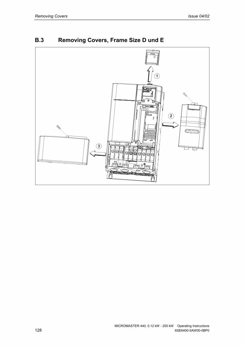
Removing Covers Issue 04/02
MICROMASTER 440, 0.12 kW - 200 kW Operating Instructions128 6SE6400-5AW00-0BP0
B.3 Removing Covers, Frame Size D und E
1
3
2

Issue 04/02 Removing Covers
MICROMASTER 440, 0.12 kW - 200 kW Operating Instructions6SE6400-5AW00-0BP0 129
B.4 Removing Covers, Frame Size F
1
3
2
19 mm AF

Removing the I/O Board Issue 04/02
MICROMASTER 440, 0.12 kW - 200 kW Operating Instructions130 6SE6400-5AW00-0BP0
C Removing the I/O Board
1
2
3
NOTICE1. Only a small amount of pressure is required to release the I/O Board catch.

Issue 04/02 Removing ‘Y’ Cap
MICROMASTER 440, 0.12 kW - 200 kW Operating Instructions6SE6400-5AW00-0BP0 131
D Removing ‘Y’ Cap
D.1 Removing ‘Y’ Cap, Frame Size A
21
LK 700

Removing ‘Y’ Cap Issue 04/02
MICROMASTER 440, 0.12 kW - 200 kW Operating Instructions132 6SE6400-5AW00-0BP0
D.2 Removing ‘Y’ Cap, Frame Size B und C
12
3

Issue 04/02 Removing ‘Y’ Cap
MICROMASTER 440, 0.12 kW - 200 kW Operating Instructions6SE6400-5AW00-0BP0 133
D.3 Removing ‘Y’ Cap, Frame Size D und E

Removing ‘Y’ Cap Issue 04/02
MICROMASTER 440, 0.12 kW - 200 kW Operating Instructions134 6SE6400-5AW00-0BP0
D.4 Removing ‘Y’ Cap, Frame Size F

Issue 04/02 Removing ‘Y’ Cap
MICROMASTER 440, 0.12 kW - 200 kW Operating Instructions6SE6400-5AW00-0BP0 135
D.5 Removing ‘Y’ Cap, Frame Size FX
Unscrew2 screws
Torx TX20and remove
brackets

Removing ‘Y’ Cap Issue 04/02
MICROMASTER 440, 0.12 kW - 200 kW Operating Instructions136 6SE6400-5AW00-0BP0
D.6 Removing ‘Y’ Cap, Frame Size GX
Unscrew2 screws
Torx TX20and remove
brackets

Issue 04/02 Applicable Standards
MICROMASTER 440, 0.12 kW - 200 kW Operating Instructions6SE6400-5AW00-0BP0 137
E Applicable Standards
European Low Voltage DirectiveThe MICROMASTER product range complies with the requirements of the LowVoltage Directive 73/23/EEC as amended by Directive 98/68/EEC. The unitsare certified for compliance with the following standards:EN 60146-1-1 Semiconductor inverters - General requirements and line
commutated invertersEN 60204-1 Safety of machinery - Electrical equipment of machines
European Machinery DirectiveThe MICROMASTER inverter series does not fall under the scope of theMachinery Directive. However, the products have been fully evaluated forcompliance with the essential Health & Safety requirements of the directivewhen used in a typical machine application. A Declaration of Incorporation isavailable on request.
European EMC DirectiveWhen installed according to the recommendations described in this manual,the MICROMASTER fulfils all requirements of the EMC Directive as defined bythe EMC Product Standard for Power Drive Systems EN61800-3.
Underwriters LaboratoriesUL and CUL LISTED POWER CONVERSION EQUIPMENT 5B33 for use in apollution degree 2.NOTE: UL certification is presently in progress
ISO 9001Siemens plc operates a quality management system, which complies with therequirements of ISO 9001.

List of Abbreviations Issue 04/02
MICROMASTER 440, 0.12 kW - 200 kW Operating Instructions138 6SE6400-5AW00-0BP0
F List of Abbreviations
AC Alternating Current
AIN Analog Input
AOP Advanced Operator Panel
BOP Basic Operator Panel
CT Constant Torque
DC Direct Current
DIN (Digital Input
DS Drive State
EEC European Economic Community
ELCB Earth Leakage Circuit Breaker
EMC Electro-Magnetic Compatibility
EMI Electro-Magnetic Interference
FAQ Frequently Asked Questions
FCC Flux Current Control
FCL Fast Current Limitation
I/O Input and Output
IGBT Insulated Gate Bipolar Transistor
LCD Liquid Crystal Display
LED Light Emitting Diode
PID Proportional, Integral und Differential
PLC Programmable Logic Controller
PTC Positive Temperature Coefficient
QC Quick Commissioning
RCCB Residual Current Circuit Breaker
RCD Residual Current Device
RPM Revolutions Per Minute
SDP Status Display Panel
VT Variable Torque
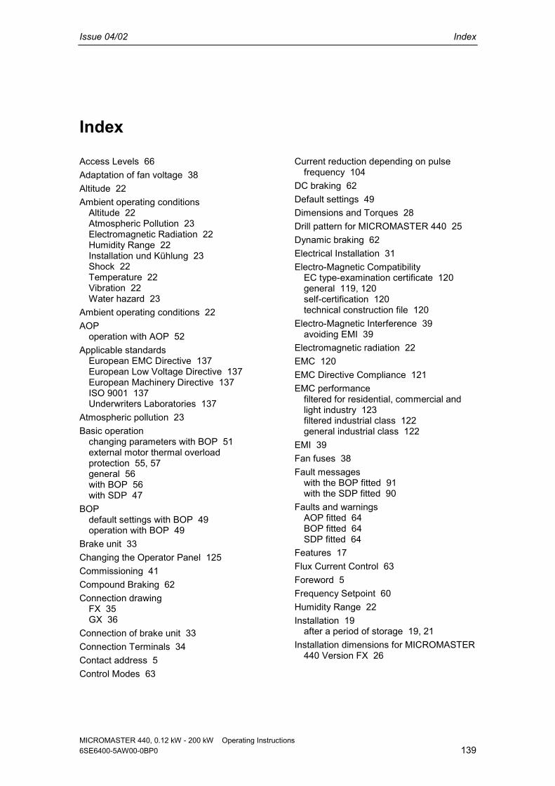
Issue 04/02 Index
MICROMASTER 440, 0.12 kW - 200 kW Operating Instructions6SE6400-5AW00-0BP0 139
Index
Access Levels 66Adaptation of fan voltage 38Altitude 22Ambient operating conditions
Altitude 22Atmospheric Pollution 23Electromagnetic Radiation 22Humidity Range 22Installation und Kühlung 23Shock 22Temperature 22Vibration 22Water hazard 23
Ambient operating conditions 22AOP
operation with AOP 52Applicable standards
European EMC Directive 137European Low Voltage Directive 137European Machinery Directive 137ISO 9001 137Underwriters Laboratories 137
Atmospheric pollution 23Basic operation
changing parameters with BOP 51external motor thermal overloadprotection 55, 57general 56with BOP 56with SDP 47
BOPdefault settings with BOP 49operation with BOP 49
Brake unit 33Changing the Operator Panel 125Commissioning 41Compound Braking 62Connection drawing
FX 35GX 36
Connection of brake unit 33Connection Terminals 34Contact address 5Control Modes 63
Current reduction depending on pulsefrequency 104
DC braking 62Default settings 49Dimensions and Torques 28Drill pattern for MICROMASTER 440 25Dynamic braking 62Electrical Installation 31Electro-Magnetic Compatibility
EC type-examination certificate 120general 119, 120self-certification 120technical construction file 120
Electro-Magnetic Interference 39avoiding EMI 39
Electromagnetic radiation 22EMC 120EMC Directive Compliance 121EMC performance
filtered for residential, commercial andlight industry 123filtered industrial class 122general industrial class 122
EMI 39Fan fuses 38Fault messages
with the BOP fitted 91with the SDP fitted 90
Faults and warningsAOP fitted 64BOP fitted 64SDP fitted 64
Features 17Flux Current Control 63Foreword 5Frequency Setpoint 60Humidity Range 22Installation 19
after a period of storage 19, 21Installation dimensions for MICROMASTER
440 Version FX 26
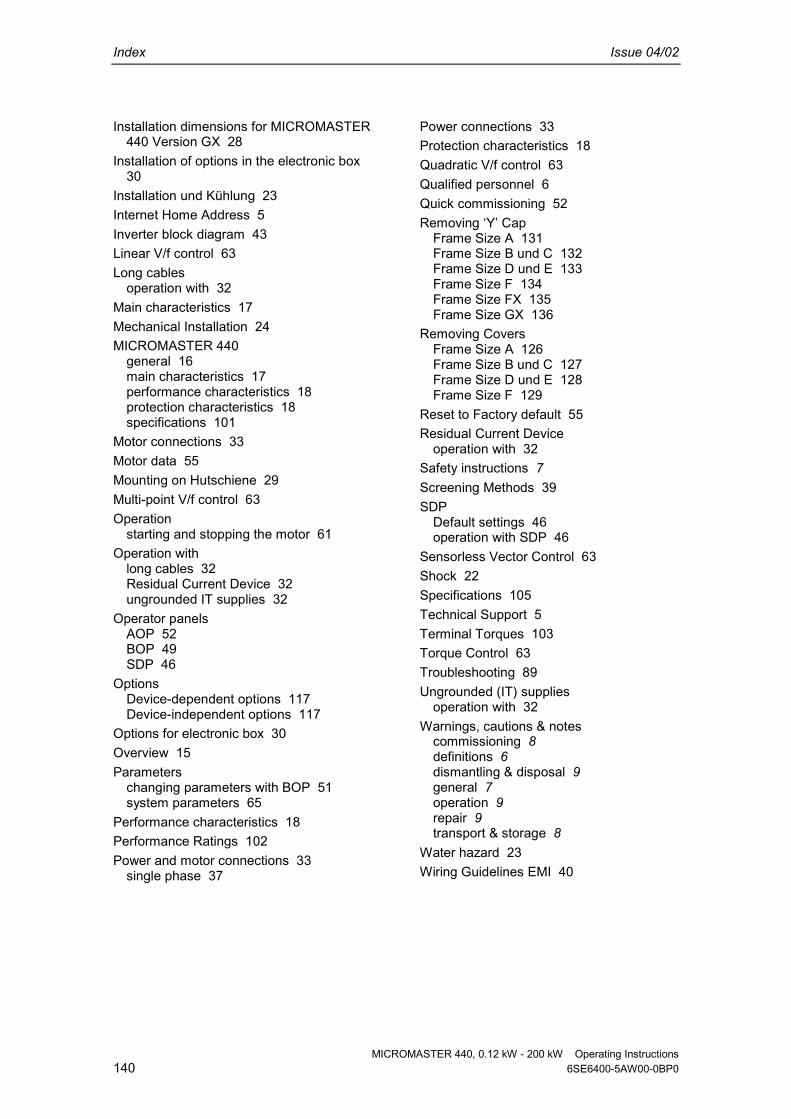
Index Issue 04/02
MICROMASTER 440, 0.12 kW - 200 kW Operating Instructions140 6SE6400-5AW00-0BP0
Installation dimensions for MICROMASTER440 Version GX 28
Installation of options in the electronic box30
Installation und Kühlung 23Internet Home Address 5Inverter block diagram 43Linear V/f control 63Long cables
operation with 32Main characteristics 17Mechanical Installation 24MICROMASTER 440
general 16main characteristics 17performance characteristics 18protection characteristics 18specifications 101
Motor connections 33Motor data 55Mounting on Hutschiene 29Multi-point V/f control 63Operation
starting and stopping the motor 61Operation with
long cables 32Residual Current Device 32ungrounded IT supplies 32
Operator panelsAOP 52BOP 49SDP 46
OptionsDevice-dependent options 117Device-independent options 117
Options for electronic box 30Overview 15Parameters
changing parameters with BOP 51system parameters 65
Performance characteristics 18Performance Ratings 102Power and motor connections 33
single phase 37
Power connections 33Protection characteristics 18Quadratic V/f control 63Qualified personnel 6Quick commissioning 52Removing ‘Y’ Cap
Frame Size A 131Frame Size B und C 132Frame Size D und E 133Frame Size F 134Frame Size FX 135Frame Size GX 136
Removing CoversFrame Size A 126Frame Size B und C 127Frame Size D und E 128Frame Size F 129
Reset to Factory default 55Residual Current Device
operation with 32Safety instructions 7Screening Methods 39SDP
Default settings 46operation with SDP 46
Sensorless Vector Control 63Shock 22Specifications 105Technical Support 5Terminal Torques 103Torque Control 63Troubleshooting 89Ungrounded (IT) supplies
operation with 32Warnings, cautions & notes
commissioning 8definitions 6dismantling & disposal 9general 7operation 9repair 9transport & storage 8
Water hazard 23Wiring Guidelines EMI 40

MICROMASTER 440, 0.12 kW - 200 kW Operating Instructions6SE6400-5AW00-0BP0 141
Suggestions and/or Corrections
Suggestions
Corrections
To:Siemens AGAutomation & Drives GroupSD VM 4P.O. Box 3269
D-91050 ErlangenFederal Republic of Germany
For Publication/Manual:
MICROMASTER 4400.12 kW - 200 kW
Email:[email protected] User Documentation
From
Name:
Operating Instructions
Order Number:6SE6400-5AW00-0BP0
Date of Issue: 04/02Company/Service Department
Address:
Telephone: __________ /
Telefax: ________ /
Should you come across any printingerrors when reading this publication,please notify us on this sheet.
Suggestions for improvement are alsowelcome.

MICROMASTER 440, 0.12 kW - 200 kW Operating Instructions142 6SE6400-5AW00-0BP0

MICROMASTER 440, 0.12 kW - 200 kW Operating Instructions6SE6400-5AW00-0BP0 143

Siemens AGBereich Automation and Drives (A&D)Geschäftsgebiet Standard Drives (SD)Postfach 3269, D-91050 ErlangenFederal Republic of Germany
© Siemens AG, 2002Subject to change without prior notice
Siemens Aktiengesellschaft Order No.: 6SE6400-5AW00-0BP0Date: 04/02
Order Number
*6SE6400-5AW00-0BP0*
Drawing Number
*G85139-K1790-U249-A1*