mm850262-1c mcal pm200
TRANSCRIPT

8/3/2019 MM850262-1c MCal PM200
http://slidepdf.com/reader/full/mm850262-1c-mcal-pm200 1/66
eurotroneurotron
EUROTRON Instruments S.p.A.Viale F.lli Casiraghi 409/413
20099 S.S.Giovanni (MI) - Italy
Tel. +39-02 248820.1 Fax +39-02 2440286
MMiiccrrooCCaall PPMM220000 SSyysstteemmHigh AccuracyMultifuntion Calibration SystemInstruction Manual MM850262 ed.1c

8/3/2019 MM850262-1c MCal PM200
http://slidepdf.com/reader/full/mm850262-1c-mcal-pm200 2/66
_____________________________________ _____________________________________ Instruction Manual MM850262 ed. 01c
______________________________________ 2 _______________________________________
INTRODUCTORY NOTE
ATTENTION: THIS MANUAL MUST BE REFERRED TO INSTRUMENTS WITH SERIAL NUMBER 0019811.
This publication contains operating instructions, as well as a description of the principles of operation, of
MicroCal PM200 (Multifunction Calibration System ). This information covers all models of the
instrument, including the basic equipment and its options and accessories.
For all instructions and information relevant with MicroCal 200 base Calibrator please refer to the
Instruction manual n. MM850216 ver.7 or successive.
This manual is a complete “USER GUIDE”, providing step-by-step instructions to operate MicroCal
PM200 in each of its designed functions.
The information contained in this publication is derived in part from proprietary and patent data of
Eurotron Instruments . This information has been prepared for the sole purpose of assisting operating
personnel in the efficient use of the instrument.
The publication of this information does not convey any right to use or reproduce it for any other purpose
than in connection with the installation, operation, and maintenance of the equipment described herein.The instrument uses sophisticated analog and digital technologies. Repair and service require highly
qualified personnel. Eurotron will supply, on request, all pertinent instructions and procedures for service
and calibration. Eurotron specialists will be glad to give any technical support you may require.
The instrument is powered by the internal group of four Ni-Cd rechargeable batteries installed into the
MicroCal 200 base unit. An external battery charger module, with power voltage set at 100, 115 or 230
Vac, is supplied as a standard with the above unit. Always check battery charger data with the available
mains supply voltage.
! IMPORTANT NOTE !INSERT THE FLUID OUTLET TUBE IN THE "VENTILATION OUTPUT" CONNECTOR ON THE PRESSURE MODULE ;
OTHERWISE THE OVERPRESSURE VALVES AND THE FLUID OUTLET WILL NOT BE ACTIVE.
! WARNING !DON'T APPLY A PRESSURE HIGHER THAN 125% FULL SCALE TO THE CALIBRATOR .
IF AN EXCESSIVE PRESSURE, HIGHER THAN THE STATED ONE, IS APPLIED, PERSONNEL MAY RECEIVE INJURIES THAT
COULD, IN EXTREME CIRCUMSTANCES BE LETHAL . FURTHERMORE, POSSIBLE SERIOUS DAMAGES CAN OCCUR TO THE
INSTRUMENT, THE USER’S SYSTEM AND EQUIPMENT.
! WARNING !DO NOT USE LIQUID.
USE ONLY AIR OR NON -CORROSIVE, NON- OXIDANT NON-CONDENSATING AND NON-EXPLOSIVE GASES AS PRESSURE
MEDIA. DIFFERENT FLUIDS COULD SERIOUS DAMAGE THE PNEUMATIC COMPONENTS AND THE INTERNAL SENSORS.
! WARNING !THE INTERNAL HAND PUMP IS ABLE TO GENERATE PRESSURE UP TO 20 BAR WITHOUT CONSIDERING THE EXTERNAL
COMPONENTS CONNECTED TO IT: TAKE CARE USING IT.
! IMPORTANT NOTE !FOR A CORRECT USE OF THE PRESSURE MODULE, IT WILL BE CONNECTED TO A MICROCAL 200/200+ CALIBRATOR
USING FIRMWARE VER. 4.000 OR SUCCESSIVE.IF THIS CONDITION DOESN ’T TAKE PLACE, USE THE ENCLOSED PC SOFTWARE “FLASHUPG” OR CONTACT EUROTRON
TECNICAL DEP. TO RECEIVE THE FLOPPY DISK .THE UPGRADE OPERATIVE PROCEDURES ARE DESCRIBED IN MICROCAL 200 INSTRUCTION MANUAL (CAT. MM850215
VER. 7 OR ABOVE IT).

8/3/2019 MM850262-1c MCal PM200
http://slidepdf.com/reader/full/mm850262-1c-mcal-pm200 3/66
_____________________________________ _____________________________________ Instruction Manual MM850262 ed. 01c
______________________________________ 3 _______________________________________
CONTENTS
1 PERFORMANCE 51.1 Specifications--------------------------------------------------------------------------------------------------------7
1.2 Instrument codes ---------------------------------------------------------------------------------------------------9
2 GENERAL FEATURES 112.1 Input and output flexibility--------------------------------------------------------------------------------------- 11
2.2 Firmware------------------------------------------------------------------------------------------------------------11
2.3 External pressure sensors ------------------------------------------------------------------------------------11
2.4 Digital interface---------------------------------------------------------------------------------------------------- 11
2.5 Scale factor function ---------------------------------------------------------------------------------------------12
2.6 Square root function ---------------------------------------------------------------------------------------------12
2.7 Pressure measurement damping ---------------------------------------------------------------------------12
2.8 Data logger mode ------------------------------------------------------------------------------------------------ 12
2.9 CALPMAN application software-------------------------------------------------------------------------------12
2.10 Power supply ------------------------------------------------------------------------------------------------------ 132.11 Case -----------------------------------------------------------------------------------------------------------------13
2.12 Report of calibration ---------------------------------------------------------------------------------------------13
3 PHYSICAL DESCRIPTION 14
4 FUNCTIONAL DESCRIPTION 154.1 Power supply ------------------------------------------------------------------------------------------------------ 15
4.2 Microcontroller-----------------------------------------------------------------------------------------------------15
4.3 Firmware------------------------------------------------------------------------------------------------------------16
4.4 Built-in pressure transducers --------------------------------------------------------------------------------- 16
4.5 External pressure transducers -------------------------------------------------------------------------------16
4.6 Auxiliary V and mA input-----------------------------------------------------------------------------------------16
4.7 Pneumatic assembly--------------------------------------------------------------------------------------------16
4.8 Built-in hand pump----------------------------------------------------------------------------------------------- 174.9 Volume adjuster --------------------------------------------------------------------------------------------------17
4.10 Ventilation valve ---------------------------------------------------------------------------------------------------18
4.11 Pressure inputs ---------------------------------------------------------------------------------------------------18
4.12 Ventilat ion output -------------------------------------------------------------------------------------------------18
5 PRE-OPERATIONAL CHECK 19
6 CONNECTIONS 206.1 Pneumatic connections -----------------------------------------------------------------------------------------20
6.2 Electrical connections ------------------------------------------------------------------------------------------- 21
6.3 Switch input connection-----------------------------------------------------------------------------------------22
7 OPERATION 247.1 Power "ON"--------------------------------------------------------------------------------------------------------- 24
7.2 Display slot swapping------------------------------------------------------------------------------------------- 25
7.3 Display slot scrolling -------------------------------------------------------------------------------------------- 26
7.4 Configuration review (status)----------------------------------------------------------------------------------26
7.5 Autorange-----------------------------------------------------------------------------------------------------------28
7.6 Parameter or sensor selection -------------------------------------------------------------------------------28
7.6.1 Sensor configuration ----------------------------------------------------------------------------------------28
7.6.2 Scale factor configuration ---------------------------------------------------------------------------------- 29
7.6.3 How to set a 4/20mA sensor as External pressure-------------------------------------------------31
7.7 Pressure measurement damping ---------------------------------------------------------------------------33
7.8 InP data memory-------------------------------------------------------------------------------------------------- 33
7.9 Pressure switch test---------------------------------------------------------------------------------------------34
8/3/2019 MM850262-1c MCal PM200
http://slidepdf.com/reader/full/mm850262-1c-mcal-pm200 4/66
_____________________________________ _____________________________________ Instruction Manual MM850262 ed. 01c
______________________________________ 4 _______________________________________
7.10 Pressure module setting ---------------------------------------------------------------------------------------35
7.11 Zero function -------------------------------------------------------------------------------------------------------36
7.12 Pump pressure/vacuum mode -------------------------------------------------------------------------------37
7.13 Leak test-------------------------------------------------------------------------------------------------------------37
7.13.1 Leak test setting-----------------------------------------------------------------------------------------------37
7.13.2 Leak test operation-------------------------------------------------------------------------------------------38
7.14 Installation of an external pressure sensor ---------------------------------------------------------------38
7.14.1 Table DownLoad sof tware ---------------------------------------------------------------------------------39
7.14.2 Installation ------------------------------------------------------------------------------------------------------39
7.14.3 How to operate ------------------------------------------------------------------------------------------------39
7.15 UserCalPM: User calibration program------------------------------------------------------------------40
7.15.1 Installation ------------------------------------------------------------------------------------------------------40
7.15.2 How to operate ------------------------------------------------------------------------------------------------41
8 APPLICATIONS 438.1 How to prepare the pneumatic circuit -----------------------------------------------------------------------43
8.1.1 Connecting to a pressurized circuit----------------------------------------------------------------------438.1.2 Using the built-in hand pump -----------------------------------------------------------------------------43
8.2 How to verify a pressure Trx------------------------------------------------------------------------------------44
9 CALPMAN - APPLICATION SOFTWARE 47
10 DIGITAL INTERFACE 4810.1 Communication protocol from MicroCal PM200 to a PC-----------------------------------------------48
11 MAINTENANCE 5611.1 Faulty operating conditions------------------------------------------------------------------------------------56
11.2 Protections ----------------------------------------------------------------------------------------------------------57
11.2.1 Logical protections -------------------------------------------------------------------------------------------57
11.2.2 Electronic protections----------------------------------------------------------------------------------------58
11.2.3 Pneumatic protections --------------------------------------------------------------------------------------58
11.3 Recommendations -----------------------------------------------------------------------------------------------5811.3.1 General recommendations --------------------------------------------------------------------------------58
11.3.2 Safety recommendations -----------------------------------------------------------------------------------58
11.5 Storage --------------------------------------------------------------------------------------------------------------59
11.6 Spare parts & Accessories-------------------------------------------------------------------------------------59
12 CERTIFICATES 6112.1 Warranty terms ----------------------------------------------------------------------------------------------------61
12.2 Letter of conformity -----------------------------------------------------------------------------------------------61
APPENDIX 62A1 EMC Conformity---------------------------------------------------------------------------------------------------63

8/3/2019 MM850262-1c MCal PM200
http://slidepdf.com/reader/full/mm850262-1c-mcal-pm200 5/66
_____________________________________ _____________________________________ Instruction Manual MM850262 ed. 01c
______________________________________ 5 _______________________________________
1 PERFORMANCE
MicroCal PM200 Pressure Module is designed to be connected to standard MicroCal 200 or MicroCal
200+ realising a portable, compact, rugged and accurate multifunction calibration system (MicroCal
PM200 System).
MicroCal PM 200 System
The high accuracy Pressure Module is designed to operate together with standard MicroCal 200
calibrator extending the overall performances (see MicroCal 200 bulletin n. 08-44) to relative (gauge),
absolute and differential pressure measurements and calibrations.
The Microcal PM200 System represents the most advanced, powerful and versatile portable indicator-
simulator available on the market today for measurements and simulations of :
• millivolt
• volt
• milliampere (active and passive loop)
• ohm
• temperature with thermocouples
• temperature with resistance
thermometers
• frequency
• pulse
• pressure
All most common pressure technical units are selectable through a simple keyboard procedure.
The leather case contains both the Pressure module and the Signal calibrator and is extremely useful
for a practical use since it allows to leave one hand free for instrument under test tuning.
A standard 19” rack format is available on request for installation in laboratory calibration work station.
Pressure Module and MicroCal 200 communicate through a dedicated digital port simplifying base
calibration and service.
MicroCal PM200 Pressure Module
The Pressure Module has been developed using a microcontroller technique to combine high flexibilityof performances with a special procedure of calibration using computerised methods and storing into
memory the relevant calibration data.
The relative / differential pressure measurement uses a temperature compensated silicon
piezoresistive transducer individually characterised for linearity and temperature coefficient.
The individual sensor temperature/linearization matrix data are stored in a non-volatile EEPROM
resident in the module.
In order to make the calibration activity easy the PM200 System can be specified with an internal single
or twin pressure transducer up to 20 bar and, as an option, with a built-in hand pressure pump, a
volume adjuster for fine control, a ventilation valve for pressure release and a pressure port.

8/3/2019 MM850262-1c MCal PM200
http://slidepdf.com/reader/full/mm850262-1c-mcal-pm200 6/66
_____________________________________ _____________________________________ Instruction Manual MM850262 ed. 01c
______________________________________ 6 _______________________________________
As it is important that the maximum pressure
for the device under test is not exceeded, a
safety LIMITS function may be selected to
automatically block the pumping action at the
desired set pressure.
An external pressure transducer can be
connected for pressure up to 700 bar.
The case made in Alluminium, has the front panel extremely rugged if you instal l the 20 bar built-in hand
pressure pump.
The Pressure Module is powered by the Ni-Cd rechargeable batteries installed in the MicroCal 200.
MicroCal 200 Indicator-Simulator
You can use your laboratory MicroCal 200 with an easy firmware upgrade from your Personal Computer
and connecting the Pressure Module. Both pressure and electrical parameter readings are indicated on
the high contrast graphic LCD display installed on MicroCal 200.The required pressure technical unit can be selected through a simplified procedure.
The selection of the operative mode is made on the standard keyboard of the MicroCal 200 through
dedicated menu-driven procedures.

8/3/2019 MM850262-1c MCal PM200
http://slidepdf.com/reader/full/mm850262-1c-mcal-pm200 7/66
_____________________________________ _____________________________________ Instruction Manual MM850262 ed. 01c
______________________________________ 7 _______________________________________
1.1 Specifications
• Pressure and ∆∆P ranges:See table C
• Electrical and temperature ranges:Signal Calibrator
see MicroCal 200 Instruction Manual cod. MM850216
active and passive loops direct operations
Pressure Module inputs
from 0 to 30.0000 Vdc
from 0 to 22.0000 mA with active and passive loops direct operations
• Overpressures:125% of f.s. without losing the calibration characteristic for the active sensor
• Pressure media:
Internal sensorscompatible with non-reducing, non-oxidant, non-condensing and non-explosive gases
External sensors
Gauge : sensors compatible with all 316SS gases
Differential : wet/wet sensors with 35 bar maximum line pressure
• Pressure connections :Quick release coupling
• Accuracy (built-in sensors) :±0.05% rdg between 0% and 100% f.s.
The zero error is ±0.006% f.s. of the active sensor in use.The relative accuracy shown are stated for 90 days and includes non-linearity, histeresis and repeatibility. The
average temperature coefficient, inside the temperature compensated range, is ±0.002% of reading per °C (w.t.r.
+23°C / +73°F).
• Accuracy (external sensors) :±(0.1% f.s. + 1 digit) between 0% and 100% f.s.
• Accuracy (mV, V and mA module input) :±(0.05% rdg + 0.01% f.s.)The relative accuracy shown are stated for 90 days and the operative conditions are from +0°C to +40°C (+32 °F
to +104 °F). Outside the above temperature band, the temperature drift is ±0.005% / °C
• Inpendence (voltage channel):> 1 MΩ
• Shunt (current channel):< 60 Ω
• Maximum voltage input (voltage channel):50 Vdc
• Maximum current input (current channel):50 mA
• Shortcircuit protection (loop power supply):Fuse + Electronic
• Overcurrent protection (current channel):Fuse
• Maximum load (passive loop):900Ω at 20mA
• Keyboard selectable technical units:mbar, bar, Pa, kPa, MPa, kg/cm
2, kg/m
2, psi, mmH2O, cmH2O, mH2O, torr, atm, lb/ft
2, inH2O, inH2O4,
ftH2O, inH2O4, mmHg, cmHg, mHg, inHg, custom.
• Scale factor and square root:for direct flow measurement
• Response time:

8/3/2019 MM850262-1c MCal PM200
http://slidepdf.com/reader/full/mm850262-1c-mcal-pm200 8/66
_____________________________________ _____________________________________ Instruction Manual MM850262 ed. 01c
______________________________________ 8 _______________________________________
2 readings per second nominal
• Display:The graphic LCD display installed in the MicroCal 200
• Power supply :From MicroCal 200 through the interface cable
• System autonomy:4 hours without printing and backlight
• Data memory:up to 1500 data records. It can be extended up to 300000 data records using the PCMCIA memory
card installed in the MicroCal 200+
• EMC compliance:EN 50082-2 (March 1995) directive
• Operating temperature:from -5 °C to +50 °C (+23°F to +122°F) with dry fluid
• Temperature compensated range:
from +0 °C to +45 °C (+32°F to +113°F)• Thermal error:
Every instrument is calibrated at 23 °C ±1 °C (73°F ±1°F).
• Storage temperature:from -20 °C to +60 °C (-4°F to +140°F).
• Case:Pressure module : Aluminium
Signal Calibrator : Injection moulded ABS with internal metal coating in compliance with EMC
System: Leather case to contains all the system
• External dimensions:250 x 60 x 172 mm (module only)
250x156x172 mm (PM system)
270x170x267 mm (PM system + leather case)
• Weight:net 3 kg (module only) 7 kg (PM system)

8/3/2019 MM850262-1c MCal PM200
http://slidepdf.com/reader/full/mm850262-1c-mcal-pm200 9/66
_____________________________________ _____________________________________ Instruction Manual MM850262 ed. 01c
______________________________________ 9 _______________________________________
1.2 Instrument codes
MicroCal PM200 cat. 3222 - A - B - C - D - E - F - G
The multifunction Pressure calibrator require a MicroCal 200 to operate. The base MicroCal PM200 System is
equipped with pressure sensor(s) and supplied with a set of fast coupling connectors, a TTL/RS232 adapter
(BB530001), a leather carrying case, a Report of Calibration and an Instruction Manual.
Table A - Signal Calibrator0 None (customer has one MicroCal 200 available)
2 MicroCal 200 MAV (MicroCal 200 without Tc & Rtd measuring and all generation capabilities)4 MicroCal 200 MAV+ (MicroCal 200 without measuring and generation of Tc and Rtd)
6 MicroCal 200 cat. 3916
8 MicroCal 200+ cat. 3918
Table B - Signal Calibrator mains power supply0 None (only for A=0; the pressure module is powered by Microcal 200)
1 120 V USA plug
2 230 V Schuko plug
3 240 V UK plug
4 230 V European plug
5 100 V USA/Japan plug
Table C - Pressure Module - Internal Sensors (only for non-reducing, non-condensing, non-oxidant and
non-explosive gases)0 No internal sensors only external sensors capabilities
1 Dual from -0.8 to 2 bar (30 PSI) and from –0.8 to 20 bar (300 PSI) automatic selection (Gauge and
differential).
2 Single from -0.8 to 2 bar (30 PSI) (Gauge)
3 Single from -0.8 to 20 bar (300 PSI) (Gauge)
4 Dual from -0.8 to 2 bar (30 PSI) (Gauge and differential)
5 Dual from -0.8 to 20 bar (300 PSI) (Gauge and differential)
6 Dual from 0 to 2 bar (30 PSI) and from 0 to 20 bar (300 PSI) automatic selection (Absolute and
differential).
7 Single from 0 to 2 bar (30 PSI) (Absolute)
8 Single from 0 to 20 bar (300 PSI) (Absolute)
9 Dual from 0 to 2 bar (30 PSI) (Absolute and differential)
A Dual from 0 to 20 bar (300 PSI) (Absolute and differential)
Z Special
Table D - Hand Pumps0 None
1 Built-in 20 bar (300 PSI) pressure pump
2 External 10 bar (150 PSI) cylinder type pump (F3280004)
3 External -0.8 bar (-10 PSI) cylinder type pump (F3280005)
4 External 14 bar (210 PSI) pliers type pump (F3280001)
5 Built-in from -0.8 to 20 bar (300 PSI) pressure and vacuum pump
6 External 2 bar (30 PSI) pliers type pump (F3280003)
7 External 20 bar (300 PSI) pliers type pump (F3280002)
8 External 350 bar (5000 PSI) oil pump (F3280008)
9 External 700 bar (10000 PSI) oil pump (F3280009)

8/3/2019 MM850262-1c MCal PM200
http://slidepdf.com/reader/full/mm850262-1c-mcal-pm200 10/66
_____________________________________ _____________________________________ Instruction Manual MM850262 ed. 01c
______________________________________ 10 _______________________________________
Table E - Accessories0 None
2 BSP kit (use 22 if you need two kits)each kit include: n.1 1/8" BSPM (EE170067)
n.1 1/4" BSPM (EE170069)
4 NPT kit (use 44 if you need two kits)
each kit include: n.1 1/8" NPTM (EE170068)
n.1 1/4" NPTM (EE170070)
6 Electrical signal test lead kit (EE300040)
8 Rilsan tube holder (EE170066) + 2m Rilsan tube F6/4 mm (EE370048)
A CalpMan software for PC (BB260097)
C LinMan software for PC (BB260096)
E LogMan software for PC (BB260095)
G TTL/RS232 isolated adapter (BB530004)
L External impact printer (BB490000)
Table F - External pressure sensors0 No External pressure sensors
1 35 bar (500 PSI) (Gauge) 316SS (EE830050)
3 70 bar (1000 PSI) (Gauge) 316SS (EE830051)
5 150 bar (2000 PSI) (Gauge) 316SS (EE830052)
7 350 bar (5000 PSI) (Gauge) 316SS (EE830053)
9 700 bar (10000 PSI) (Gauge) 316SS (EE830054)
E Barometric (from 750 mbar to 1150 mbar)
G 175 mbar (2.5 PSI) (Differential) wet/wet *
L 350 mbar (5 PSI) (Differential) wet/ wet *
N 1 bar (15 PSI) (Differential) wet/ wet *
P 10 bar (150 PSI) (Differential) wet/ wet *
R 20 bar (300 PSI) (Differential) wet/ wet *
Z Special
Table G - Report of Calibration1 Eurotron Report
* Maximum line pressure 35 bar

8/3/2019 MM850262-1c MCal PM200
http://slidepdf.com/reader/full/mm850262-1c-mcal-pm200 11/66
_____________________________________ _____________________________________ Instruction Manual MM850262 ed. 01c
______________________________________ 11 _______________________________________
2 GENERAL FEATURES
2.1 Input and output flexibility
An advanced flexibility of performance has been achieved using the microcontroller technique.
Each instrument, through a menu-driven procedure, allows simultaneous measurement of pressure
(gauge, absolute or differential) and of electric and thermoelectric signals according to MicroCal 200
multifunction a two channel multifunction calibrator.
The microcontroller performs linearization and temperature compensation of the piezoresistive
pressure sensor using the characterization data stored in the pressure module memory.
The operative set-up mode is simplified by a sequence of menu pages that only require <Select> and
<Enter> instructions.
A full set of operators' notes are memory stored allowing a direct operator's assistance and instruction.
Any relevant instruction may be recalled through the <Help> key.
One or two pressure sensors can be installed inside the pressure module according to the customer’s
requirements.
Different ranges of external pressure sensors are also available to be connected directly with the
MicroCal PM200 pressure module to extend the pressure range up to 700 bar.
The pressure module can be equipped, on request, with a built-in pressure/vacuum pump from -0.8 to
20 bar complete with ventilation valve and volume adjuster.
It is possible to display simultaneously the generated pressure value and the electrical input signals to
achieve eg. the automatic inspection of pressure transmitters.
2.2 Firmware
The operating system firmware handles all logic instructions to the internal peripheral circuits, performs
the direct communication with MicroCal 200 and controls the electropneumatic circuits.
The application system firmware is resident on the non-volatile memory (EEPROM) of the
microprocessor chip. It is used to store the installation parameters (auto-calibration data, program
data, etc.).
2.3 External pressure sensors
A 12 pin connector, assembled on the left-side, is used to connect external sensors. It is possible to
have a direct connection with one of the available (see table F par. 1.2) sensors for absolute, gauge or
differential measurement.
Using the same connector makes possible the connection with pre-linearized current (active andpassive loop) and voltage output.
2.4 Digital interface
A dedicated digital port is used by the Pressure Module to communicate with MicroCal 200 through a 25
pins connector on the rear panel. A multipolar cable with 2 connectors, is supplied as a standard.
A full bi-directional TTL level digital interface for communication with computerised systems is available.
A RS232 adapter with galvanic insulation is available on request.

8/3/2019 MM850262-1c MCal PM200
http://slidepdf.com/reader/full/mm850262-1c-mcal-pm200 12/66
_____________________________________ _____________________________________ Instruction Manual MM850262 ed. 01c
______________________________________ 12 _______________________________________
2.5 Scale factor function
Easy menu-driven set-up to read or simulate electrical signal values in terms of engineering units.Four programmable alphanumeric characters are available on the display to show the parameter
symbol (i.e. mbar, mmwc, etc.). The display on MicroCal 200, will indicate the scaled input value.
2.6 Square root function
It can be programmed during the set-up procedure to obtain direct readings of flow from an ∆P
transmitter signal. The display limits (on MicroCal 200) are -9999 and +30000.
2.7 Pressure measurement damping
To allow measurement of unstable input signals using a special algorithm based on a programmable
digital low pass filter.
2.8 Data logger mode
Data logging can be performed automatically. Simply key-in the interval time and the system logs, all
required readings are completely unattended.
After recording, data can be transferred, via the serial port, into a PC with a text format or compatible
format with the most common spreadsheets such as Lotus, Excel, Paradox, etc.
This allows data to be easily accessed and displayed in agreement with the user’s existing report
format.
However used, the instrument information is available, organized, accurate and verified for all record
keeping requirements.
Flash memory and PCMCIA card extend the memory storage capability practically without any limits(more than 300.000 data records with 1 MBytes PCMCIA card).
2.9 CALPMAN application software
The MicroCal PM200 System is the ideal calibration system to be used as part of a company in
compliance with ISO 9000 series of standards for quality management.
A supporting software for DOS and Windows (CalpMan - Calibration Procedure manager) is available to
transfer a selection of calibration routines from a PC to the internal memory of the equipment in order to
simplify the field calibration activity by selecting the required Tag number.
CalpMan can handle the following pieces of information :
• Tag identification code
• Tag auxiliary pieces of information
• Operator/Inspector name
• Programmable test points
• Next calibration date
• Programmable scaling
• Linear and square operation

8/3/2019 MM850262-1c MCal PM200
http://slidepdf.com/reader/full/mm850262-1c-mcal-pm200 13/66
_____________________________________ _____________________________________ Instruction Manual MM850262 ed. 01c
______________________________________ 13 _______________________________________
• Damp and damp band setting
• Automatic error capture
• Error band
The serial number of the equipment, the date and the time are automatically entered, using the internal
real time clock, during the calibration activity.
The calibration data (“before” and “after” data) will be memory stored and transferred back to the PC to
document the inspection activity that allows to build a quality control chart/data bank from a single
calibration sheet to a detailed historical report.
2.10 Power supply
The MicroCal PM200 system can operate using an external charger circuit and an internal
rechargeable battery. MicroCal PM200 basic module provides, through the digital interface connector,
the dc voltage levels for the circuitry of the pressure module.The system can operate from mains line continuously without removing the battery
2.11 Case
The leather case is designed for an easy hand held operation and transport.
The instrument case is rugged and designed to improve the compliance with EMC.
The system case, made in shock-resistant and rugged material, is protected from any electric
interference. It allows the use of the instrument in three different ways :
• Portable and table top with standard leather case for an easy transport and use.
• Portable and table top with optional leather case with an accessory site for a very practical use.
• Panel or rack mounting (DIN cut-out) with the special optional kit.
2.12 Report of calibration
Each module is factory calibrated against Eurotron Standards, that are periodically certified by an
International recognised Laboratory to ensure traceability, and shipped with a Report of Calibration
stating the nominal and actual values and the deviation errors.
Every external pressure sensor, supplied successively by the MicroCal PM200 order, had a dedicated
Report of calibration.
A special calibration report can be supplied on request.
8/3/2019 MM850262-1c MCal PM200
http://slidepdf.com/reader/full/mm850262-1c-mcal-pm200 14/66
_____________________________________ _____________________________________ Instruction Manual MM850262 ed. 01c
______________________________________ 14 _______________________________________
3 PHYSICAL DESCRIPTION
The MicroCal PM200 system consist of two main sections : a signal calibrator module (it is possible to
use a MicroCal 200 or a MicroCal 200+ indifferently) and a Pressure Module.
The MicroCal PM200 Pressure Module for MicroCal 200 and MicroCal 200+ consists of an aluminium
rugged and compact case, a mother board with all basic functions, a daughter board for the auxiliary
and power circuits, one or two built-in pressure sensors, an optional built-in 20 bar pressure pump
complete of volume adjuster and ventilation valve.
The two sections of the MicroCal PM200 System (the Pressure Module and MicroCal 200) are joined
together using a 25 pin flat cable and they are inserted in a special leather case, with shoulder strap,
supplied as a standard accessory. The leather case is also extremely useful for a practical use since it
allows to leave one hand free for instruments under test tuning.
A dedicated digital port allows the communication with MicroCal 200 universal calibrator. The
communication between the two sections is allowed by a flat cable supplied as a standard accessory.
The case of the pressure module is aluminium made to improve the compliance with EMC and to
increase the rugged feature of the system.
A standard 19" rack format kit is available on request for installation in a laboratory calibration work
station.

8/3/2019 MM850262-1c MCal PM200
http://slidepdf.com/reader/full/mm850262-1c-mcal-pm200 15/66
_____________________________________ _____________________________________ Instruction Manual MM850262 ed. 01c
______________________________________ 15 _______________________________________
4 FUNCTIONAL DESCRIPTION
The MicroCal PM200 System block diagram is shown below :
MicroCal 200 / 200+Multifunction Signal Calibrator
Power Supply
Microcontroller
Solenoid
Controller
A/D Converterand
Analog switch
PneumaticAssembly
see pneumaticdrawing
External transducer input Auxiliary V / mA input
Volume Adjuster
Hand pump
High pressure input
Low pressure Input
Ventilation Valve
P reference 25 pins interfaceconector
PH sensor
PL sensor
PRESSURE MODULE PM200
Ventilation output
• Power Supply
• Microcontroller (CPU + memory)
• Input circuits
• Pneumatic assembly
• Internal pressure sensors
• Hand pump
4.1 Power supply
The system is powered by a group of 4 rechargeable batteries installed inside the MicroCal 200
calibrator. The batteries are charged using an external power supply module. The pressure module is
powered by MicroCal 200 internal rechargeable batteries through the 25 pin flat cable.
The voltage (approximately 5 Vdc) is connected to the input of a switching circuit to generate the
reference voltages for the pressure transducers, the analogic and digital circuits. The power supply
circuit, is also configured as a voltage multiplier to generate a voltage of 24 Vdc for the final output stage
operating both into active or passive loops. The above voltage levels are required to work with an
external load up to 900 Ω to supply the external current loop.
4.2 Microcontroller

8/3/2019 MM850262-1c MCal PM200
http://slidepdf.com/reader/full/mm850262-1c-mcal-pm200 16/66
_____________________________________ _____________________________________ Instruction Manual MM850262 ed. 01c
______________________________________ 16 _______________________________________
The MicroCal PM200 system has 2 independent microprocessor systems. One, installed on the
MicroCal 200 calibrator module, handles all the logic functions of the system, the communication with
the pressure module, drives the digital keyboard and the display, performs the linearization for non
linear electrical signals, compensates for the reference junction temperature and for the electrical input
and output channels.
The second one, installed in the pressure module, handles all the logic functions of the instrument,
performs the linearization for pressure transducers, compensates for the reference junction
temperature, drives the digital display and acknowledges all the operator’s instructions.
The core of the circuit is a single-chip microcomputer that uses HCMOS technology to provide the low
power characteristics and high noise immunity of CMOS plus the high speed operation of HMOS.
The microprocessor includes a 2kbytes EEPROM memory (to maintain the sensor data linearization)
and is interfaced with MicroCal 200 using a dedicated serial communication interface. A non-volatile
memory is used to maintain the other data (the external sensor data linearization, the application
firmware, the instrument setting data, ecc.).
4.3 FirmwareThe operating system firmware handles all logic instructions to the internal peripheral circuits and
performs the computation of the linearization equations. The application system firmware is resident
on the non-volatile memory (EEPROM) of the microprocessor chip.
4.4 Built-in pressure transducers
MicroCal PM200 pressure module can have 1 or 2 piezoresistive pressure sensors with a built-in
temperature sensor. The linearity and temperature compensation data are memory stored into
EEPROM.
4.5 External pressure transducers
A 12 pin connector, on the left side of the module, is used to connect external sensors:
• MicroCal PM200 is able to connect external piezoresistive pressure sensors for absolute, gauge
and differential measurements up to 700 bar. Sensors are full-characterised for linearity and
temperature. They are supplied by Eurotron with a PC software to download the data matrix into
EEPROM using the serial interface. An extended number of sensors are available by Eurotron to
extend the pressure ranges of the MicroCal PM200 system. All sensors are supplied complete with
2 meters of cable and a 12 pin connector.
• MicroCal PM200 is able to use pre-linearized current (with active and passive loop) and voltage
outputs connecting them to the auxiliary input.
4.6 Auxiliary V and mA input
The pressure module is designed with an auxiliary voltage and current input for general purpose: up to
22 mA active and passive current loop and voltage up to 30 Volt. Using the MicroCal PM200 sale factor
function, it is possible to visualize the input signal with the desired scale and engineering unit.
4.7 Pneumatic assembly
The pneumatic Pressure module assembly, see the following figure, can be divided into two main
blocks :
8/3/2019 MM850262-1c MCal PM200
http://slidepdf.com/reader/full/mm850262-1c-mcal-pm200 17/66
_____________________________________ _____________________________________ Instruction Manual MM850262 ed. 01c
______________________________________ 17 _______________________________________
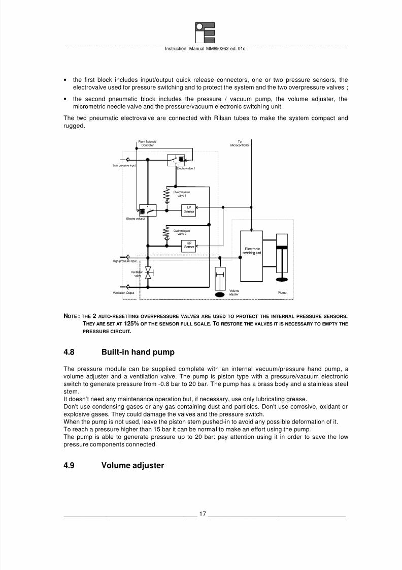
• the first block includes input/output quick release connectors, one or two pressure sensors, the
electrovalve used for pressure switching and to protect the system and the two overpressure valves ;
• the second pneumatic block includes the pressure / vacuum pump, the volume adjuster, themicrometric needle valve and the pressure/vacuum electronic switching unit.
The two pneumatic electrovalve are connected with Rilsan tubes to make the system compact and
rugged.
LPSensor
HPSensor
From SolenoidController
Electro valve 1
Electro valve 2
Overpressurevalve 1
Overpressurevalve 2
Volumeadjuster
Ventilationvalve
Electronicswitching unit
Pump
ToMicrocontroller
Low pressure input
High pressure input
Ventilation Output
NOTE : THE 2 AUTO-RESETTING OVERPRESSURE VALVES ARE USED TO PROTECT THE INTERNAL PRESSURE SENSORS.THEY ARE SET AT 125% OF THE SENSOR FULL SCALE. TO RESTORE THE VALVES IT IS NECESSARY TO EMPTY THE
PRESSURE CIRCUIT.
4.8 Built-in hand pump
The pressure module can be supplied complete with an internal vacuum/pressure hand pump, a
volume adjuster and a ventilation valve. The pump is piston type with a pressure/vacuum electronic
switch to generate pressure from -0.8 bar to 20 bar. The pump has a brass body and a stainless steel
stem.
It doesn’t need any maintenance operation but, if necessary, use only lubricating grease.Don't use condensing gases or any gas containing dust and particles. Don't use corrosive, oxidant or
explosive gases. They could damage the valves and the pressure switch.
When the pump is not used, leave the piston stem pushed-in to avoid any possible deformation of it.
To reach a pressure higher than 15 bar it can be normal to make an effort using the pump.
The pump is able to generate pressure up to 20 bar: pay attention using it in order to save the low
pressure components connected.
4.9 Volume adjuster

8/3/2019 MM850262-1c MCal PM200
http://slidepdf.com/reader/full/mm850262-1c-mcal-pm200 18/66
_____________________________________ _____________________________________ Instruction Manual MM850262 ed. 01c
______________________________________ 18 _______________________________________
The volume adjuster is used for a fine regulation of the pressure in the pneumatic test circuit. The
regulator consists of a brass body interlocked with a fine threaded stainless steal stem for a stable and
fine positioning of the piston connected to it.
For a correct use, follow the same recommendation and maintenance instruction as the built-in hand
pump.
4.10 Ventilation valve
The ventilation valve is used to discharge the gas from the pneumatic circuit proportionally. Remember
to use it for slowly discharges to avoid possible damage to the sensors and to the pneumatic
components connected to the testing circuit.
If the MicroCal PM200 system is connected with external pressure sources, first disconnect thepressure module from the circuit; after this operation open the ventilation valve (the quick coupling
connectors are auto-blocking type: they close the pneumatic circuit automatically).
4.11 Pressure inputs
Two quick coupling auto-blocking pressure connectors are assembled on the module front-panel:
PORT1 (HP) and PORT2 (LP) connectors. They are stainless steel made and a complete connector kit
is supplied with the module for connections with the test circuit.
PORT1 pressure input is used to measure and to generate gauge or absolute pressure.
PORT2 is used only as low pressure input for differential measurements.
4.12 Ventilation output
A quick coupling auto-blocking pressure connector, used for ventilation output, is assembled on the
module left-side. It is stainless steel made. A connector complete with 3 meters of tube is supplied with
the module to permit the gas outlet when the operator uses the ventilation valve, or when the secure
valves are active.

8/3/2019 MM850262-1c MCal PM200
http://slidepdf.com/reader/full/mm850262-1c-mcal-pm200 19/66
_____________________________________ _____________________________________ Instruction Manual MM850262 ed. 01c
______________________________________ 19 _______________________________________
5 PRE-OPERATIONAL CHECK
Remove the instrument from its packing case and remove any shipping ties, clamps, or packing
materials.
Carefully follow any instruction given on any attached tags.
Inspect the instrument from scratches, dents, damages to case corners, etc. which may have occurred
during shipment.
If any mechanical damage is noted, report the damage to the shipping carrier and then notify Eurotrondirectly or its nearest agent and retain the damaged packaging for inspection.
A label, on the back of the instrument case, indicates the serial number of the instrument. The serial
number is also shown on the display when you switch the instrument on.
Refer to this number for any inquiry for service, spare parts supply or application and technical support
requirements.
Eurotron will keep a data base with all information regarding your instrument.
8/3/2019 MM850262-1c MCal PM200
http://slidepdf.com/reader/full/mm850262-1c-mcal-pm200 20/66
_____________________________________ _____________________________________ Instruction Manual MM850262 ed. 01c
______________________________________ 20 _______________________________________
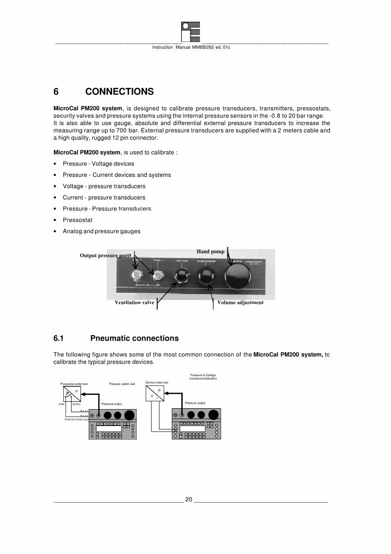
6 CONNECTIONS
MicroCal PM200 system, is designed to calibrate pressure transducers, transmitters, pressostats,
security valves and pressure systems using the internal pressure sensors in the -0.8 to 20 bar range.
It is also able to use gauge, absolute and differential external pressure transducers to increase the
measuring range up to 700 bar. External pressure transducers are supplied with a 2 meters cable and
a high quality, rugged 12 pin connector.
MicroCal PM200 system, is used to calibrate :
• Pressure - Voltage devices
• Pressure - Current devices and systems
• Voltage - pressure transducers
• Current - pressure transducers
• Pressure - Pressure transducers
• Pressostat
• Analog and pressure gauges
Output pressure port
Ventilation valve Volume adjustment
Hand pump
6.1 Pneumatic connections
The following figure shows some of the most common connection of the MicroCal PM200 system, to
calibrate the typical pressure devices.
Pressure switch test
P
Pressure output
Pressostat under test
External contact input
COM NO/NC
Pin.11
Pin.24
Pressure to Voltagetransducer calibration
V
P
Pressure output
Device under test
+-

8/3/2019 MM850262-1c MCal PM200
http://slidepdf.com/reader/full/mm850262-1c-mcal-pm200 21/66
_____________________________________ _____________________________________ Instruction Manual MM850262 ed. 01c
______________________________________ 21 _______________________________________
Pressure to Currenttransducer calibration
with passive externa l loop
I
P
Pressure output
Device under test
+-
Pressure to Currenttransducer calibration
with active external loop
I
P
Pressure output
Device under test
+-
Pressure to Voltagetransducer calibration up to700 bar using an external
transducer
V
P
Device under test
+-V
P
External transducer upto 700 bar
External pressure
Pressure to Currenttransducer calibration
using a standardtransducer
I
P
Device under test withactive current loop
+-I
P
Reference pressuretransducer with active
current loop
External pressure
+-
Pin 3
Pin 4
WARNING
TEST CIRCUITS USING PRESSURE HIGHER THAN 10 BAR , COULD BE INJURIOUS FOR PERSONNEL :PAY ATTENTION TO IT.
WARNING
USING EXTERNAL PRESSURE SENSORS WITH PRESSURE HIGHER THAN 10 BAR, INSTALL THE SENSORS DIRECTLY ONTHE PLANT. DO NOT USE EXTENSION TUBES.
6.2 Electrical connections
The pressure module has a circular 12 pin connector, on the right side, used either for the connection
with external transducers or for voltage (30 V f.s.) or for active and passive current loop (22 mA f.s.)
measurements.
1 8
92 12 7
3 10 11 6
4 5
1= Power supply 24 Volt2= Volt Input3= mA Input4= GND
5= 0V Su pply ext. Transducer
6= -SIG ext. Transducer7= +SIG ext. Transducer
8= -5 Volt Supply9= -5 Volt Feedback10= 0V Feedback11= -Temp
12= +Temp
MicroCal PM200 mA input channel can operate directly on active and passive loops. This means that
the instrument has an internal power supply able to compensate for the voltage level present into the
loop.
If the internal power supply is connected to a short circuit or if the load requires more than 22 mA, a
message “Overrng” will be displayed simultaneously with an acustic intermittance signal.

8/3/2019 MM850262-1c MCal PM200
http://slidepdf.com/reader/full/mm850262-1c-mcal-pm200 22/66
_____________________________________ _____________________________________ Instruction Manual MM850262 ed. 01c
______________________________________ 22 _______________________________________
If the internal power supply is connected to a load higher than 900Ω, a message "Overload" will be
displayed and an acustic intermittance signal will set up the error condition.
If the current or the voltage inputs measure a value higher than the limits, the message "Overrng" will be
displayed.
The internal power supply uses an electronic circuit to limit the maximum output current to 25 mA and a
fuse, to preserve itself from external overvoltage and overcurrent.
Passive loopThis type of connection is to be used when the external loop is not equipped with the loop power
supplied.
The calibrator can be, as an example, connected directly to a recorder, controller , etc. with input circuits
configured for current measurements.
Active loop
This type of connection must be used when the external loop is equipped with its loop power supplied.The power supply is not required to be disconnected.
The loop circuit must be opened and Microcal PM200 connections are placed in series on the loop.
The following figure shows some examples of input/output wiring of the instrument:
Trx P.S.
ACTIVE EXTERNAL LOOP
Pin 4 Pin 2
(current measurements)
TRX
PASSIVE EXTERNAL LOOP
Pin 2 Pin 1
(current measurements)
Trx P.S.
ACTIVE EXTERNAL LOOP
Pin 4 Pin 3
(voltage measurements)
TRX
PASSIVE EXTERNAL LOOP
(voltage measurements)
Pin 4 Pin 3 Pin 1
The signal inputs are mainly designed to connect calibrated pressure transmitters with pre-linearized
output to be used as reference for calibrations.
6.3 Switch input connection
The flat cable of the MicroCal PM200 system has an auxiliary male 25 pin standard connector to permit
the connection with pressostat and termostat switches. The external contact input (pin 11 and pin 24)

8/3/2019 MM850262-1c MCal PM200
http://slidepdf.com/reader/full/mm850262-1c-mcal-pm200 23/66
_____________________________________ _____________________________________ Instruction Manual MM850262 ed. 01c
______________________________________ 23 _______________________________________
allows to perform the special calibration automatic routine in order to calibrate the mentioned
components.
See the MicroCal 200 calibrator module for more information and recommendations.

8/3/2019 MM850262-1c MCal PM200
http://slidepdf.com/reader/full/mm850262-1c-mcal-pm200 24/66
_____________________________________ _____________________________________ Instruction Manual MM850262 ed. 01c
______________________________________ 24 _______________________________________
7 OPERATION
All the procedures and programming operations on MicroCal PM200 system, can be made using
MicroCal 200 keyboard and display.
This manual describes only the operations or instructions relative to the pressure capability added with
the Pressure module to the system. For other configurations and operation procedures, please refer to
the MicroCal 200 instruction manual (cat. MM850216 version 07 or later).
The instrument should be used in environments where the temperature does not exceed the specified
limits (from -10°C to +55°C) and where the relative humidity is lower than 95%
NOTE: ALL NUMERIC VALUES SHOWN IN THE FIGURES OF THIS MANUAL ARE INDICATIVE AND LISTED AS AN EXAMPLE.
During the set-up and memory loading remember that the instructions of the manual related to key
operations have the following meaning:
• <A> + <B> Press the <A> key and keeping the pressure on it, press then the <B> key.
• <A>, <B> Press in sequence first the <A> key and then the <B> key.
If an operative message (eg. “Instrument config”, ”Set”, ”Esc”, etc) is displayed under the <NUM> or
<LAMP> or <RAMP> key this instruction can be entered pressing the correspondent key.
7.1 Power "ON"
! IMPORTANT NOTE !FOR A CORRECT USING OF THE PRESSURE MODULE, IT WILL BE CONNECTED WITH A MICROCAL 200/200+
CALIBRATOR USING FIRMWARE VER. 4.000 OR SUCCESSIVE.IF THIS CONDITION IS NOT VERIFIED , USE THE ENCLOSED PC SOFTWARE “FLASHUPG” OR CONTACT THE EUROTRON
TECNICAL DEP. TO RECEIVE THE FLOPPY DISK .THE UPGRADE OPERATIVE PROCEDURE ARE DESCRIBED IN THE MICROCAL 200 INSTRUCTION MANUAL (CAT.
MM850215 VER. 7 OR SUCCESSIVE).
To power the instrument on press the <ON> key; the following indication will appear for few seconds.
™ MicroCal 200 ™Version 4.00
S/N 0010880
m ar m
NOTE : IF THE PRESSURE MODULE IS CONNECTED, THE DISPLAY INDICATES THE INTERNAL SENSOR INSTALLED ANDTHEIR RANGES IN THE FIRST ROW .
The instrument will run an auto-diagnostic routine for the self-checking of critical circuits and
components.
The serial number, the version number of the firmware installed on the instrument and the next
calibration date are important pieces of information for servicing activities.
To achieve a better performance in terms of accuracy wait at least for 5 minutes for the instrument to
warm up.
When possible avoid using the display back-light in order to save the charge of the battery and to
limit the heating inside the instrument, so that you can obtain most accurate results.
8/3/2019 MM850262-1c MCal PM200
http://slidepdf.com/reader/full/mm850262-1c-mcal-pm200 25/66
_____________________________________ _____________________________________ Instruction Manual MM850262 ed. 01c
______________________________________ 25 _______________________________________
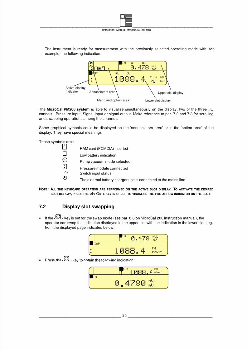
The instrument is ready for measurement with the previously selected operating mode with, for
example, the following indication:
°C
0.478 mVLmV
IN
OUT
çç 1088.4 68
Rji
Tc K
Annunciators area
Menù and option area
Upper slot display
Lower slot display
AL OL
AL OLI
O
Active displayIndicator
The MicroCal PM200 system is able to visualise simultaneously on the display, two of the three I/O
cannels : Pressure input, Signal Input or signal output. Make reference to par. 7.2 and 7.3 for scrolling
and swapping operations among the channels.
Some graphical symbols could be displayed on the 'annunciators area' or in the 'option area' of the
display. They have special meanings.
These symbols are :
RAM card (PCMCIA) inserted
Low battery indication
Pump vacuum mode selected
Pressure module connected
Switch input status
The external battery charger unit is connected to the mains line
NOTE : ALL THE KEYBOARD OPERATION ARE PERFORMED ON THE ACTIVE SLOT DISPLAY . TO ACTIVATE THE DESIRED
SLOT DISPLAY, PRESS THE <IN-OUT> KEY IN ORDER TO VISUALISE THE TWO ARROW INDICATOR ON THE SLOT.
7.2 Display slot swapping
• If the < > key is set for the swap mode (see par. 8.6 on MicroCal 200 instruction manual), the
operator can swap the indication displayed in the upper slot with the indication in the lower slot ; eg.
from the displayed page indicated below:
mbar
0.478mVLmV
IN
InPçç 1088.4
PH
I
P
• Press the < > key to obtain the following indication:
IN
ç
.
InP
ç 1088. mbar
mVLmV
PH
I
P

8/3/2019 MM850262-1c MCal PM200
http://slidepdf.com/reader/full/mm850262-1c-mcal-pm200 26/66
_____________________________________ _____________________________________ Instruction Manual MM850262 ed. 01c
______________________________________ 26 _______________________________________
• If the < > key is set for the scroll mode, the operator can swap the indication displayed in the upper
slot with the one in the lower slot pressing <Shift> + < > keys.
7.3 Display slot scrolling
• If the < > key is set for the scroll mode (see par. 8.6 on MicroCal 200 instruction manual), the
operator can scroll the channel displayed in the lower slot of the display with the pressure channel
(if the PM200 pressure module is connected); eg. from the displayed page indicated below:
°C
0.478mVLmV
IN
OUT
çç .
I
O
• Press the < > key to obtain the following indication:
InP
ç .
IN
ç
0.748 mV
PLmbar
mVLI
P
• If the < > key is set for the swap mode, the operator can scroll the channels pressing <Shift> +
< > keys.
NOTE : IF THE PM200 PRESSURE MODULE IS NOT CONNECTED , A 'NO MODULENO MODULE ' MESSAGE WILL BE DISPLAYED.
7.4 Configuration review (status)
Press the <STATUS> key to obtain a sequence of pages with the relevant header.
Please, refer to MicroCal 200 instruction manual (par. 8.5) to complete the following information.
• Input P statusInput P status
A typical indication will be the following:
InP : 0.30 mbar PL
Cnv : 0.015 %
MIN : 0.20
MED : 0.30
Input P status
0.10 mbarMAX : 0.40
Rst
+-
Information related respectively to:
-InPInP Actual operating mode, measured value and technical unit
-CnvCnv % of full scale
-MinMin minimum value
-MaxMax maximum value
-MedMed median value with actual positive and negative deviations

8/3/2019 MM850262-1c MCal PM200
http://slidepdf.com/reader/full/mm850262-1c-mcal-pm200 27/66
_____________________________________ _____________________________________ Instruction Manual MM850262 ed. 01c
______________________________________ 27 _______________________________________
The Minimum and Maximum values can be reset using the <Rst> key.
Press the <STATUS> key to enter the pages relevant to the internal status as it follows:
• Input P Internal statusInput P Internal status
Information related respectively to:
− sensor range (internal and external sensors);
− Battery voltage;
− Serial number of the pressure module;
− Firmware version number
− Next calibration date (only when programmed)
PL F.S.: 2000.0mbar
PH F.S.: 20000.0mba
Pext F.S.: 1# no availab. mb
Battery :5.00
S/N 00132
Internal status InP
vers. 1.00Pressure Modu
• Press the <t> key to display the sensor IDs (if applicable) assigned at the pressure sensor.
PL ID: SN 000000
PH ID: SN 999999
Pext ID: ------------------
Battery :5.00 V
S/N 0013288
Internal status InP
vers. 1.000Pressure Module
• Press the <t> key to display the values (if applicable) measured by the pressure sensor.
PL : 200.0 mbarPH : No active mbar
Pext : 1# No active mbar
Battery :5.00 V
S/N 0013288
Internal status InP
vers. 1.000Pressure Module
• Scale factor X1, X2, X3, X4, X5 Set StatusScale factor X1, X2, X3, X4, X5 Set Status
Five pressure input scale factor configurations can be reviewed.
A typical indication will be the following:
Fun : linear
E.U. : mbarype :
X1 Set status InP
Low : 0.000
High : 100.000ow x: .High x: 500.000
%
%
Pext ID: #1 ------------
Prst : none
− Type: internal sensor
− Pext ID : external sensor ID
− Low: pressure signal - zero
− High: pressure signal - full scale
− Low x: display scaled zero indication
− High x: display scaled full scale indication
− Fun: linear or square
− E.U.: Symbol of the engineering unit
− Prst : Select the various preset values for scaling function

8/3/2019 MM850262-1c MCal PM200
http://slidepdf.com/reader/full/mm850262-1c-mcal-pm200 28/66
_____________________________________ _____________________________________ Instruction Manual MM850262 ed. 01c
______________________________________ 28 _______________________________________
§ Press any <ss > or <tt > key to select the next or the previous display of the five pages of "X"
pressure input status.
7.5 Autorange
If 2 internal pressure sensors with different ranges are installed, it is possible to activate the autorange
function. This function switches automatically the pneumatic circuit of the PM200 pressure module
towards the correct internal pressure sensor to perform a better accuracy and to preserve the low range
sensor.
§ Press the <Menù> key to obtain 'Autorng on' menu message.
§ Press <Autorng> to toggle between -On- and -Off- state, to activate/disable the function. The
message "ARN" will appear on the active slot display.
7.6 Parameter or sensor selectionTo select the pressure parameter or the sensor required by the application, in any measuring or
simulation mode, follow the procedure indicated below:
• Switch the instrument -ON-;
• Select the required -InP- mode using the <IN-OUT> key (pointer on the relevant mode)
• Press the <SELECT> key to obtain eg. the following menu page indicating all pressure ranges and
sensors available for the measurement channel:
Set Esc Set InP Type
PE-PL PL-PE PE-PH PH-PE
X X1 X2 X3 X4 X5
Type PL PH Pext PL-PH PH-PL
− PLPL low pressure sensor
− PHPH high pressure sensor
− PextPext external pressure sensor
− PL-PHPL-PH differential between low and high pressure sensor
− PH-PLPH-PL differential between high and low pressure sensor
− PE-PLPE-PL differential between external and low pressure sensor
− PL-PEPL-PE differential between low and external pressure sensor
− PE-PHPE-PH differential between external and high pressure sensor
− PH-PEPH-PE differential between high and external pressure sensor
• Press <ss > <tt > or <çç > <èè > cursor keys to select the required sensor;
• Press the <ENTER> key to memory load the selection; the instrument will return to the previousoperative mode with the new selected parameter or sensor;
• By pressing the <ESC> key, instead of the <ENTER> one, the instrument will not acknowledge any
variation and will return to the previous parameter or sensor.
7.6.1 Sensor configuration
This procedure is automatically enabled only when the relevant channel is programmed for pressure
measurements.
• Press the <SELECT> key to enter the procedure obtaining the sensor menù page, as it follows :
8/3/2019 MM850262-1c MCal PM200
http://slidepdf.com/reader/full/mm850262-1c-mcal-pm200 29/66
_____________________________________ _____________________________________ Instruction Manual MM850262 ed. 01c
______________________________________ 29 _______________________________________
Set Esc Set InP Type
PE-PL PL-PE PE-PH PH-X X1 X2 X3 X4 X5
Type PL PH Pext PL-PH PH-
• Select the required pressure parameter moving the cursor using <ss > <tt > or <çç > <èè > cursor
keys.
• Press the <Set> key to obtain, for example, the following indication :
Set Esc Set Pressure PH
Pext ID: 1# -----------
E.U. : mbar
E.U.E.U. (engineering unit) = mbar, bar, mmH2O, custom
Pext IDPext ID (external sensor) = to abilitate one of the five pre-set sensors
• Press <ss > and <tt > keys to select the required parameter to be adjusted;
• Press the <SET> key to enable the selected parameter adjustment;
• Press <ss > and <tt > keys to select the required application configuration;
• Press the <ENTER> key to memory store the new selection;
• Press the <ESC> key twice to return to the operative mode.
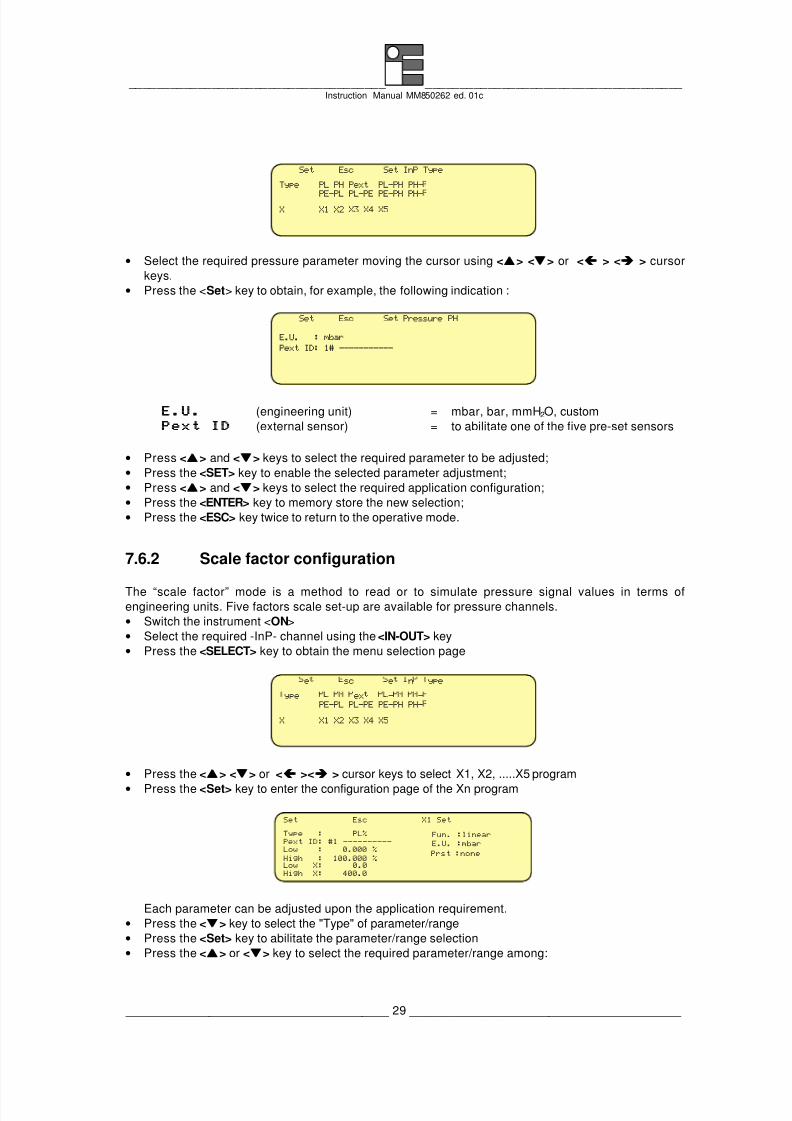
7.6.2 Scale factor configuration
The “scale factor” mode is a method to read or to simulate pressure signal values in terms ofengineering units. Five factors scale set-up are available for pressure channels.
• Switch the instrument <ON>
• Select the required -InP- channel using the <IN-OUT> key
• Press the <SELECT> key to obtain the menu selection page
e sc e n ype
PE-PL PL-PE PE-PH PH-
X X1 X2 X3 X4 X5
ype ex - -
• Press the <ss > <tt > or <çç ><èè > cursor keys to select X1, X2, .....X5 program
• Press the <Set> key to enter the configuration page of the Xn program
Set Esc X1 Set
High X: 400.0
Type : PL%
Low : 0.000 %
High : 100.000 %Low X: 0.0
Fun. :linear
E.U. :mbar
Prst :none
Pext ID: #1 ----------
Each parameter can be adjusted upon the application requirement.
• Press the <tt > key to select the "Type" of parameter/range
• Press the <Set> key to abilitate the parameter/range selection
• Press the <ss > or <tt > key to select the required parameter/range among:
8/3/2019 MM850262-1c MCal PM200
http://slidepdf.com/reader/full/mm850262-1c-mcal-pm200 30/66
_____________________________________ _____________________________________ Instruction Manual MM850262 ed. 01c
______________________________________ 30 _______________________________________
PH%, PL%, PH%-PL%, PL%-PH%, PE%, PE%-PL%, PE%-PH%, PL%-PE%, PH%-PE%.
• Press the <ENTER> key to acknowledge the new setting and to memory store the new selection
• Press <ss > and <tt > keys to select the other required parameters using the same procedure
indicated above.
Pext ID This parameter permits to enable and to set voltage (30V f.s.) and active
or passive current loops (20mA). You can connect and linearize the output
signal from any commercial analog pressure transmitter.
Low, High These parameters are expressed as a % of the full scale of the selected
pressure sensor. If the operator selects the differential measurement (eg.
PH%-PL%), he should also consider the full scale of the highest pressure
sensor.
Prst Selects the various presets for scaling functions among : none, 0-10 V, 1-
5 V, 0-20 mA, 4-20 mA.
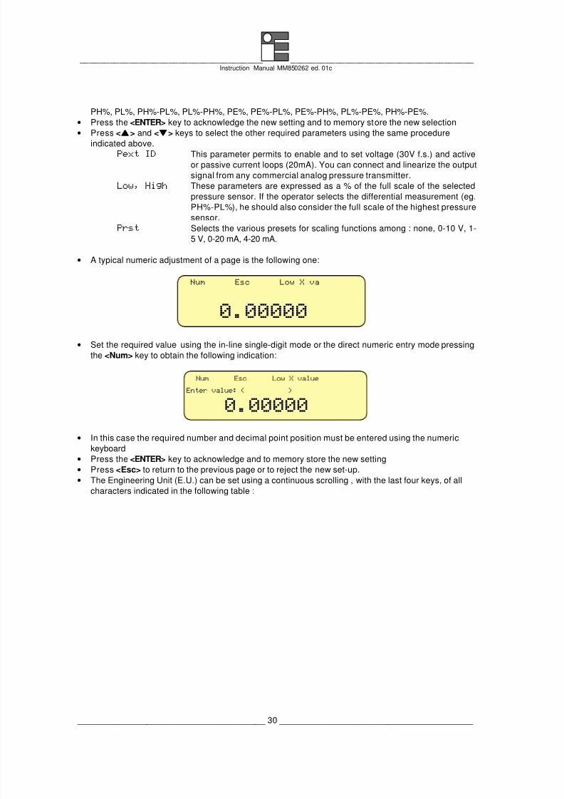
• A typical numeric adjustment of a page is the following one:
Num Esc Low X va
0.00000
• Set the required value using the in-line single-digit mode or the direct numeric entry mode pressing
the <Num> key to obtain the following indication:
Num Esc Low X value
0.00000Enter value: ( )
• In this case the required number and decimal point position must be entered using the numeric
keyboard
• Press the <ENTER> key to acknowledge and to memory store the new setting
• Press <Esc> to return to the previous page or to reject the new set-up.
• The Engineering Unit (E.U.) can be set using a continuous scrolling , with the last four keys, of all
characters indicated in the following table :

8/3/2019 MM850262-1c MCal PM200
http://slidepdf.com/reader/full/mm850262-1c-mcal-pm200 31/66
_____________________________________ _____________________________________ Instruction Manual MM850262 ed. 01c
______________________________________ 31 _______________________________________
Library of characters
7 8 O P g h
! 6 9 N Q f i" 5 : M R e j )
# 4 ; L S d K |
$ 3 < k T c l )
% 2 = J U b m z
& 1 > I V a n y
' 0 ? H W \ o x
( / @ G X _ P w
) . A F Y ^ q v
* - B E Z ] r u
+ , C D [ s t
.....
.
.
.
.....
.
.
.
....
....
.
..
.... .
• After each adjustment press the <ENTER> key to memory store new data
7.6.3 How to set a 4/20mA sensor as External pressure
Special 4/20mA external sensors are available from Eurotron. These sensors can be connected to the
standard External sensor port on the left of the pressure module. A quick procedure to set the MicroCal
PM200 parameters for your sensor is the following:
• Switch the instrument <ON>
• Select the required -InP- channel using the <IN-OUT> key
• Press the <SELECT> key to obtain the menu selection page
Set Esc Set InP Type
- - - -
X X1 X2 X3 X4 X5
Type PL PH Pext PL-PH PH-
• Press the <ss >, <tt > or <tt >, <uu > cursor keys to select X1 program
• Press the <Set> key to enter the configuration page of the X1 program
Set Esc X1 Set
High X: 10.000
Type : PExt%
Low : 19.943 %High : 99.719 %Low X: 0.000
Fun. :linear
E.U. :mbar
Prst :none
Pext ID: External mA
Each parameter can be adjusted upon the application requirement. Enclosed to the Eurotron External
sensor you have the Low and High value to be used for a correct sensor installation.
• Press the <tt > key to select the "Type" of parameter/range
8/3/2019 MM850262-1c MCal PM200
http://slidepdf.com/reader/full/mm850262-1c-mcal-pm200 32/66
_____________________________________ _____________________________________ Instruction Manual MM850262 ed. 01c
______________________________________ 32 _______________________________________
• Press the <Set> key to enter in parameter/range selection
• Press the <ss > or <tt > key to select the “PExt%” parameter/range
• Press the <ENTER> key to acknowledge the new setting and to memory store the new selection
• Press the <tt > key to select the "Pext ID" parameter/range
• Press the <Set> key to enter in parameter/range selection
• Press the <ss > or <tt > key to select the “External mA” parameter/range
• Press the <ENTER> key to acknowledge the new setting and to memory store the new selection
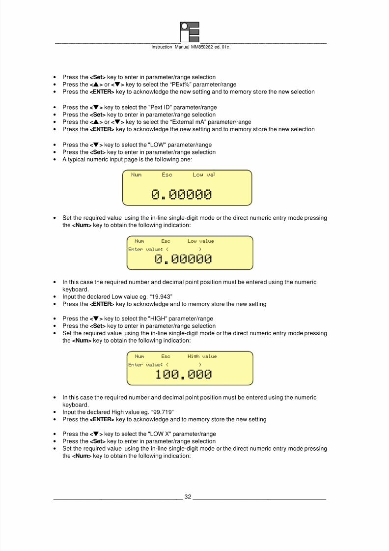
• Press the <tt > key to select the "LOW" parameter/range
• Press the <Set> key to enter in parameter/range selection
• A typical numeric input page is the fol lowing one:
Num Esc Low va
0.00000
• Set the required value using the in-line single-digit mode or the direct numeric entry mode pressing
the <Num> key to obtain the following indication:
Num Esc Low value
.Enter value: ( )
• In this case the required number and decimal point position must be entered using the numeric
keyboard.• Input the declared Low value eg. “19.943”
• Press the <ENTER> key to acknowledge and to memory store the new setting
• Press the <tt > key to select the "HIGH" parameter/range
• Press the <Set> key to enter in parameter/range selection
• Set the required value using the in-line single-digit mode or the direct numeric entry mode pressing
the <Num> key to obtain the following indication:
Num Esc High value
.Enter value: ( )
• In this case the required number and decimal point position must be entered using the numeric
keyboard.
• Input the declared High value eg. “99.719”
• Press the <ENTER> key to acknowledge and to memory store the new setting
• Press the <tt > key to select the "LOW X" parameter/range
• Press the <Set> key to enter in parameter/range selection
• Set the required value using the in-line single-digit mode or the direct numeric entry mode pressing
the <Num> key to obtain the following indication:

8/3/2019 MM850262-1c MCal PM200
http://slidepdf.com/reader/full/mm850262-1c-mcal-pm200 33/66
_____________________________________ _____________________________________ Instruction Manual MM850262 ed. 01c
______________________________________ 33 _______________________________________
Num Esc Low X value
.
Enter value: ( )
• In this case the required number and decimal point position must be entered using the numeric
keyboard.
• Input the Low scale value eg. “0.000” [bar]
• Press the <ENTER> key to acknowledge and to memory store the new setting
• Press the <tt > key to select the "HIGH X" parameter/range
• Press the <Set> key to enter in parameter/range selection
• Set the required value using the in-line single-digit mode or the direct numeric entry mode pressing
the <Num> key to obtain the following indication:
Num Esc High value
.Enter value: ( )
• In this case the required number and decimal point position must be entered using the numeric
keyboard.
• Input the High scale value eg. “10.000” [bar]
• Press the <ENTER> key to acknowledge and to memory store the new setting
• Press the <tt > key to select the "Fun." parameter/range
• Press the <Set> key to enter in parameter/range selection
•
Press the <ss
> or <tt
> key to select the “Linear” parameter/range• Press the <ENTER> key to acknowledge the new setting and to memory store the new selection
• Press the <tt > key to select the "E.U." parameter/range
• Press the <Set> key to enter in parameter/range selection
• The Engineering Unit (E.U.) can be set using a continuous scrolling , with the last four keys, of all
characters available eg. bar
• Press the <ENTER> key to acknowledge the new setting and to memory store the new selection
• Press the <tt > key to select the "Prst." parameter/range
• Press the <Set> key to enter in parameter/range selection
• Press the <ss > or <tt > key to select the “none” parameter/range
• Press the <ENTER> key to acknowledge the new setting and to memory store the new selection
7.7 Pressure measurement damping
The system is equipped with a special algorithm to allow measurements of an unstable input signal.
The average weight is programmable from 1 to 255 through the general configuration set-up procedure
described in par. 8.5 in the MicroCal 200 instruction manual.
The appropriate setting should be based on a practical test taking into consideration that to a high
programmed weight corresponds a high average effect.
7.8 InP data memory

8/3/2019 MM850262-1c MCal PM200
http://slidepdf.com/reader/full/mm850262-1c-mcal-pm200 34/66
_____________________________________ _____________________________________ Instruction Manual MM850262 ed. 01c
______________________________________ 34 _______________________________________
Are available up to 20 memory steps to store the input configuration of the pressure channel (sensor
type, engineering unit, etc.).
The operative instructions are described in the MicroCal 200 instruction manual.
7.9 Pressure switch test
When you activate this function the instrument will record the values in which the pressostat contact will
change its state (i.e. when the contact closes and when the contact reopens).
To enable this function press the <MENU> key until you reach the following menu:
mbar
0.478mVLmV
IN
InP
çç
100.0
InstrumenConfig.
PL
I
P
• Press the <Instrument config.> key to obtain:
Set Esc
Cnt state: n.open
Cnt fnct.: none
Date fmt.: dmyTime : 18:12:26
Date : 28/02/93 ID name: 1
Baud : 9600
Printer: disable
Instrument config.Pag
• Move the cursor with the <t> key to select the "Cnt fnct." line, press <Set> and with <s> or <t>
keys select "swtc InP". The pressure output of MicroCal PM200 must be connected to the pressure
input of the pressostat and the switch terminal of the pressostat must be connected to the 25-pin
connector located on the digital communication flat cable on the rear panel of the instrument.
(25 pin connector)
no/nc Contact switch
Pressure input
Ext contact input
Pressostat
• Press the <ENTER> key.
• Move the cursor with the <t> key to select the "Cnt state" line, press <Set> and with <s> or <t>
keys select: "n. open" or "n. close" depending on the normal state of the pressostat switch.
• Press the <ENTER> key twice.
• Press the <IN-OUT> key to select the channel that must be used depending on the choice previously
made (switch InP)
• Press the <MENU> key until you reach the following menu:

8/3/2019 MM850262-1c MCal PM200
http://slidepdf.com/reader/full/mm850262-1c-mcal-pm200 35/66
_____________________________________ _____________________________________ Instruction Manual MM850262 ed. 01c
______________________________________ 35 _______________________________________
mbar
0.478mVLmV
IN
InP
çç 100.0
SwtOn
PL
I
P
• Press the <Swt On> key to enable the switch test routine. At first the display will show:
mbar
InP
çç 100.0
RstSwtc
SwtOff ******** mbar
******** mbar
PLP
Use the PM200 system built-in pump and the micrometric refilled valve to increase and decrease
the pressure in the circuit.
When the condition of a change in the state of the pressostat switch is reached, the instrument willrecord the value in which the transition occurred. Moreover, when the pressostat switch returns to
the original position the instrument will record the other value in which this new transition occurred.
mbar
InP
çç 100.0
RstSwtc
SwtOff 98.0 mbar
100.0 mbar
PLP
In order to reset the recorded values for a new check press the <Rst Swtc> key.
7.10 Pressure module setting
§ To enable this function press the <IN-OUT> and the < > keys till the pressure channel (InP) will
be visualized on the lower slot display.
§ Press the <MENU> key several times till you get the following menu:
mbar
0.478 mVLmV
IN
InP
çç 100.0
SetMod
PL
I
P
• Press the key correspondent to the <Set mod> message.
Set Esc
Protect PL : enable
Safety band : 22000.0 mbar
Tare : 0 mbarTare mode : auto
Set mode function
Zero Mod. : 0.000 %
Tare mode The tare function parameter allows to lay an offset (tare) to be added to the
visualized pressure reading. The following values are possible :
auto= when selected, is considered the currently indicated value as the
Tare value.
manual= when selected, it is necessary to enter manually the required tare
value in the following parameter (Tare).

8/3/2019 MM850262-1c MCal PM200
http://slidepdf.com/reader/full/mm850262-1c-mcal-pm200 36/66
_____________________________________ _____________________________________ Instruction Manual MM850262 ed. 01c
______________________________________ 36 _______________________________________
Tare it allows to insert the tare value for the manual Tare mode.
Safety band allows to insert the maximum pressure value which can spring from the inner
pump. When this value is overcome, the system automatically disconnects
the pump from the pneumatic circuit.
Protect PL This function allows to activate the automatic protection of the low range
pressure sensor (PL). If it is selected, an 105% overpressure applied to the
PL sensor, will disconnect automatically the sensor from the circuit. The high
range sensor (PH) will remain connected anyway in order to monitor the
pressure and restore the circuits if the pressure should go back to values
which can be measured by the sensor. Disabling the function, permits to
force the pressure measurement using the PL sensor.
Note: if the function is activated and the display visualizes the message “PL
Prot”, the protection is active. It is possible to try to resume the system,
by pressing the <Shift> + <Status> keys.
Zero Mod. This parameter sets the % value (max ±20% f.s.) of the active sensor full
scale value to be used when the “zero mode” function is performed (see
following par.).
Note: “Zero Mod.” parameter can be programmed if a single sensor is active,
if the selected sensor is available, and if the pressure module
firmware is 1.004 or successive. Otherwise the message “N/A” will be
displayed.
WARNING
THE HIGH RANGE SENSOR IS ALWAYS CONNECTED TO THE PNEUMATIC CIRCUIT.DO NOT EXCEED THE LIMITS OF THE PH SENSOR TO PRESERVE IT FROM PERMANENT DAMAGE.
• Press the <tt > key to select the “Zero Mod.” parameter.
• Press the <Set> key to enable the parameter selection .
• Press the <ss > or <tt > key to select the required parameter.
• Press the <ENTER> key to acknowledge the new setting and to memory store the new selection.
7.11 Zero function
The sensors installed inside the pressure module are temperature compensated. In any case changes
of the temperature outside the characterisation limits or a using time very long, they can cause a zerodrift to the sensor. Every time the operator desires to have a very accurate pressure measurement or a
leak test, it is recommendable to perform a zero function.
This function is applicable only if in the pneumatic circuit there is a pressure value close to the “Zero
Mode” value (maximum ±3 mbar).
• To enable this function press the <IN-OUT> key to select the display pressure slot.
• Press the <MENU> key several times till you get the following menu:
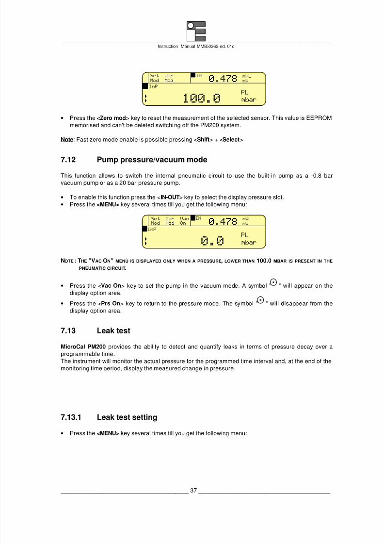
8/3/2019 MM850262-1c MCal PM200
http://slidepdf.com/reader/full/mm850262-1c-mcal-pm200 37/66
_____________________________________ _____________________________________ Instruction Manual MM850262 ed. 01c
______________________________________ 37 _______________________________________
mbar
0.478mVLmV
IN
InP
çç 100.0
Set ZerMod Mod
PL
I
P
• Press the <Zero mod> key to reset the measurement of the selected sensor. This value is EEPROM
memorised and can't be deleted switching off the PM200 system.
Note: Fast zero mode enable is possible pressing <Shift> + <Select>
7.12 Pump pressure/vacuum mode
This function allows to switch the internal pneumatic circuit to use the built-in pump as a -0.8 bar
vacuum pump or as a 20 bar pressure pump.
• To enable this function press the <IN-OUT> key to select the display pressure slot.
• Press the <MENU> key several times till you get the following menu:
mbar
0.478mVLmV
IN
InP
çç 0.0
Set Zer VacMod Mod On
PL
I
P
NOTE : THE "VAC ON" MENÙ IS DISPLAYED ONLY WHEN A PRESSURE, LOWER THAN 100.0 MBAR IS PRESENT IN THE
PNEUMATIC CIRCUIT.
• Press the <Vac On> key to set the pump in the vacuum mode. A symbol " " will appear on thedisplay option area.
• Press the <Prs On> key to return to the pressure mode. The symbol " " will disappear from the
display option area.
7.13 Leak test
MicroCal PM200 provides the ability to detect and quantify leaks in terms of pressure decay over a
programmable time.
The instrument will monitor the actual pressure for the programmed time interval and, at the end of the
monitoring time period, display the measured change in pressure.
7.13.1 Leak test setting
• Press the <MENU> key several times till you get the following menu:

8/3/2019 MM850262-1c MCal PM200
http://slidepdf.com/reader/full/mm850262-1c-mcal-pm200 38/66
_____________________________________ _____________________________________ Instruction Manual MM850262 ed. 01c
______________________________________ 38 _______________________________________
mbar
0.478mVLmV
IN
InP
çç 0.0
Set LeakLeak Test
PL
I
P
• Press the <Set Leak> key to obtain :
Set Esc
Leak time : 00:00:01Wait time : 00:00:00
Set Leak test data
Wait time is the waiting time before starting the leak test
Leak time Is the leak test duration
• Press the <tt > key to select the required parameter.
• Press the <Set> key to enable the parameter selection.
• Press the <ss > or <tt > key to modify the selected time.
• Press the <ENTER> key to acknowledge the new setting and to memory store the new selection.
• Press <ss > and <tt > keys to select the other required parameters using the same above indicated
procedure.
• Press the <ENTER> key to return to the operative menu.
7.13.2 Leak test operation
• Press the <MENU> key until you reach the following menu:
mbar
. mVLmV
IN
InP
çç 0.0
Set Leakea es
PL
I
P
• Press the <Leak test> key to obtain :
Set Esc
End :
Start :
Set Leak test running
Drop : mbar/minLeak :Wait time :
Leak time :
The system starts the countdown "wait time" up to 00 :00 :00 period (the "start" parameter shows the
actual pressure input).
After this period the "start" parameter value will be stored and the "leak time" parameter will start
("End", "Leak" and "Drop" parameters show the actual calculated values).
At the end of the leak test period, the display will indicate the final data and the message "Leak test
completed" will appear on the top of the display.
• Press the <End> key to stop the leak test procedure and to return to the main page menu.
7.14 Installation of an external pressure sensor
8/3/2019 MM850262-1c MCal PM200
http://slidepdf.com/reader/full/mm850262-1c-mcal-pm200 39/66
_____________________________________ _____________________________________ Instruction Manual MM850262 ed. 01c
______________________________________ 39 _______________________________________
On the left side of the Pressure Module is available a 12 pole circular connector to interface the
calibrator with the many pressure sensors avai lable (see the list at paragraph 11.5).
These sensors are fully supplied with 1 meter long shielded cable and connector. Moreover, it is
available a 5 meter extension cable as optional accessory for the sensors (EE420198).
Each external sensor is factory characterised by linearity and temperature and before its use, it is
necessary to download its table into the Pressure Module memory.
NOTE: IF THE SENSORS ARE ORDERED TOGETHER WITH THE PRESSURE MODULE, CHARACTERIZATION TABLES WILL BE
DOWNLOADED BY EUROTRON INTO THE MODULE MEMORY.
An easy to use Windows ®
management program for PC and characterisation tables are supplied
together with the external sensor to allow the downloading through the serial port.
After having downloaded the sensor tables in one of the five available memories of the Pressure
Module, it is possible to enable the pressure measurements with the external sensor (Pext) using the
information shown in par. 7.6.1.
7.14.1 Table DownLoad software
The floppy disks of the table management software (Tbldwn) and the characterisation tables of the
sensors are supplied together with each external pressure sensor ordered. The Pressure Module
allows to memory store up to five sensor tables. The software allows the operator to add, delete and
substitute one or more from the available tables.
7.14.2 Installation
Tbldwn program runs on IBM PC under WINDOWS 3.1. Minimum requirements are a 386 CPU with 2
Mb Ram and 1 Megabyte on hard disk, Monochromatic or colour monitor and a Microsoft mouse or a
compatible one.
In order to install Tbldwn for Windows, follow the below procedure:
• Place the Tbldwn disk in a 3.5" diskette drive;
• From the Windows Program Manager's File Menu, select <RUN>;
• Enter the filename A:SETUP.EXE (substitute the letter A for the disk drive that contains Tbldwndiskette)
• Follow on screen instructions making sure to provide the correct path to your Tbldwn directory when
prompted.
Once installed, the Tbldwn icon will appear on your Windows screen and it will be possible to boot it by
clicking on the icon as usual.
7.14.3 How to operate
Switch the calibrator on and connect it to the PC serial port using the TTL/RS232 adapter (BB530001).
Run the Tbldwnprogram; the following windows will be displayed:

8/3/2019 MM850262-1c MCal PM200
http://slidepdf.com/reader/full/mm850262-1c-mcal-pm200 40/66
_____________________________________ _____________________________________ Instruction Manual MM850262 ed. 01c
______________________________________ 40 _______________________________________
Select the communication port, the baud rate and l’ID as programmed into the calibrator. If this
information is not available refer to par 8.6 of MicroCal 200 instruction manual.
Press the <Read instrument table data> button to read the data of the installed sensor on the Pressure
Module. The sensor data will be displayed on the appropriate text area of the window program.
Press the <Select from file> button to show the table file name for the available external pressure
sensor tables. The file names will be composed by the character “P” plus the sensor serial number and
by the “.TXT” suffix (es P946630.TXT). Select the file that you would like to transfer. Select the destination
memory and press the associated <Download here!> button.
If you like to delete one or more memories, press the associated <Clear> button.
7.15 UserCalPM: User calibration programEurotron external sensors are individually characterised in linearity and temperature to assure our
declared accuracy. This information is represented by tables into the memory of the Pressure Module.
The module is able to store inside its memory, for any of the external and internal sensors, an
additional linearization user table to permit the correction due to the long term stability of the sensor.
The UserCalPM program permits to insert in the sensor range up to 5 calibration points and to
download into the calibrator the calculated linearization table. The program uses the linear interpolation
for data and the download is possible using the serial communication interface.
NOTE: THE USER’S CALIBRATION HAS NO PERMANENT EFFECTS ON THE SENSOR CHARACTERISATION TABLES SUPPLIED
BY EUROTRON . USING THE USERCALPM PROGRAM, ANYTIME IT’S POSSIBLE TO ENABLE/DISABLE THE SINGLE
USER’S CALIBRATION TABLE ANY TIME YOU LIKE.
7.15.1 Installation
UserCalPM program runs on IBM PC under WINDOWS 3.1. Minimum requirements are a 386 CPU with
2 Mb Ram and 1 Megabyte on hard disk, Monochromatic or colour monitor and a Microsoft mouse or a
compatible one.
In order to install UserCalPM for Windows, follow the below procedure:
• Place the UserCalPM disk in a 3.5" diskette drive;
• From the Windows Program Manager's File Menu, select <RUN>;

8/3/2019 MM850262-1c MCal PM200
http://slidepdf.com/reader/full/mm850262-1c-mcal-pm200 41/66
_____________________________________ _____________________________________ Instruction Manual MM850262 ed. 01c
______________________________________ 41 _______________________________________
• Enter the filename A:SETUP.EXE (substitute the letter A for the disk drive that contains UserCalPMdiskette)
• Follow on screen instructions making sure to provide the correct path to your UserCalPM directory
when prompted.
Once installed, the UserCalPM icon will appear on your Windows screen and it will be possible to boot
it by clicking on the icon as usual.
7.15.2 How to operate
There are two possibilities to insert the linearization data: manual or semiautomatic.
Using the manual mode it is possible to insert the correction data without having the pneumatic test
circuit connected to the MicroCal PM200 System; but it is necessary to have the correspondence table
between the reference and the measured value. In other cases it is necessary to build the test circuit.
NOTE: THE CORRECTION DATA MUST BE ACQUIRED ONLY WITH THE SENSORS USER ’S CALIBRATION DISABLED (IFENABLED). FOLLOW ALSO THE ZERO OFFSET (TARE) PROCEDURE BEFORE ACQUIRING CORRECTION DATA.
Switch the calibrator on and connect it to the PC serial port using the TTL/RS232 adapter (BB530001).
Run the UserCalPM program; the following window will be displayed:
Select the communication port, the baud rate and l’ID as programmed into the calibrator. If this
information is not available refer to par 8.6 of MicroCal 200 instruction manual.
Select the desired sensor to be corrected. Insert the full scale value of the selected sensor in
engineering or in mbar unit: the full scale value is necessary for the software linearization.
Select “enabled” in the “User Cal.” area to permit to insert the data. Select the desired number of
linearization segment that should be activated. For each segment insert the correspondent correction
values: in “Meas E.U.” or in “Meas %” the measured value and in “Ref E.U.” or in “Ref %” the associated
reference pressure value.
It is possible to acquire the “Meas E.U.” and “Meas %” values in semiautomatic mode reading it directly
from the calibrator. Prepare the pneumatic test circuit, apply the reference pressure value and read it
pressing the <Get Measure> button.

8/3/2019 MM850262-1c MCal PM200
http://slidepdf.com/reader/full/mm850262-1c-mcal-pm200 42/66
_____________________________________ _____________________________________ Instruction Manual MM850262 ed. 01c
______________________________________ 42 _______________________________________
Once completed the correction table, press the <Send User Cal> button to transfer the linearization
table into the Pressure Module memory.
Press <Get User Cal.> button to read the user’s calibration data from the calibrator.
8/3/2019 MM850262-1c MCal PM200
http://slidepdf.com/reader/full/mm850262-1c-mcal-pm200 43/66
_____________________________________ _____________________________________ Instruction Manual MM850262 ed. 01c
______________________________________ 43 _______________________________________
8 APPLICATIONS
The following paragraph shows test and calibration procedures for pneumatic components and
instruments with test pressure lower than 20 bar. The considered MicroCal PM200 Systemconfiguration is fully-option: two internal pressure sensors, 20 bar pressure/vacuum hand pump built-
in, volume adjuster and ventilation valve.
8.1 How to prepare the pneumatic circuit
There are two typical situations where PM200 module can be used: as a simple pressure/vacuum
indicator or as a pressure/vacuum generator/indicator. Although it is very easy to prepare the pneumatic
testing circuit, it needs all the same the operator’s care to warrant the calibrator and the testing
components safety as well as the personel’s ones (see also cap. 11).
8.1.1 Connecting to a pressurized circuit
The following procedure shows the sequential operat ions to be used to set the test circuit ready and the
operations to work MicroCal PM200 as a reference pressure indicator.
1. Connect the outlet gas tube to the ventilation output port on the left side of the module. The
ventilation port is used to discharge the gas when the operator uses the vent. Valve or when the
securing valve switch to the protection mode. The outlet tube must be connected in order to open
the blocking valve.
2. Open the ventilation valve to discharge the gas from the circuit.
3. Reset the displayed measure using the zero function (see par. 7.11). Anyway, don’t worry if you
should happen to read an unstable zero value: it can be caused by external factors such as thepneumatic circuit length, the external temperature, etc.
4. Lose the ventilation valve.
5. Connect MicroCal PM200 to the test circuit with the Rilsan tube as short as possible. Use input
PORT1 (HP) for gauge or absolute measurements or also the input PORT2 (LP) for differential
measurements.
6. Wait some minutes to stabilize the circuit pressure.
7. The measurements finished, disconnect the quick couplig connector from the module and
discharge the pressure slowly using the ventilation valve (avoid sudden pressure variations).
8.1.2 Using the built-in hand pump
If it is necessary to use MicroCal PM200 to generate and read pressure (up to 20 bar) in your testcircuit, it is necessary to follow a different operating procedure:
1. Connect the outlet gas tube to the ventilation output port on the left side of the module. The
ventilation port is used to discharge the gas when the operator uses the vent. Valve or when the
securing valve switch to the protection mode. The outlet tube must be connected in order to open
the blocking valve.
2. Open the ventilation valve to discharge the gas from the circuit.
3. Set the volume adjuster in the middle position.
4. Build the pneumatic test circuit as short as possible; connect MicroCal PM200 pressure PORT1
(HP) to the circuit.

8/3/2019 MM850262-1c MCal PM200
http://slidepdf.com/reader/full/mm850262-1c-mcal-pm200 44/66
_____________________________________ _____________________________________ Instruction Manual MM850262 ed. 01c
______________________________________ 44 _______________________________________
5. Reset the displayed measure using the zero function (see par. 7.11). Anyway, don’t worry if you
should happen to read an unstable zero value: it can be caused by external factors such as the
pneumatic circuit length, the external temperature, etc.
6. Close the ventilation valve.
7. Use “Vac On/Off” to select the pressure/vacuum pump mode.
8. Use the built-in hand pump to get as near as possible to the desired pressure circuit value.
Remember that the pump can generate pressure up to 20 bar; therefore take care if it is used with
low pressure components.
9. Use the volume adjuster for a fine regulation of the pressure in the circuit.
10. Wait some minutes to stabilize the circuit pressure.
11. The measurements finished, disconnect the quick coupling connector from the module and
discharge the pressure slowly using the ventilation valve (avoid sudden pressure variations).
8.2 How to verify a pressure Trx
This paragraph shows a typical application: the verification of pressure to current Trx. As described inpar. 7.1, the calibrator is able to display simultaneously two of the three I/O channels: pressure input
(InP), signal input (IN) and signal output (OUT).
Two different areas on the display are used to visualize the measured values and the respective
channel pieces of information: the lower slot display and the upper slot display.
°C
0.478 mVLmV
IN
OUT
çç . 68
Rji
Tc K
Annunciators area
Menù and option area
Upper slot display
Lower slot display
AL OL
AL OLI
O
Active displayIndicator
When you switch the instrument on, it loads the last programmed configuration; the displayed channel
can’t be the desired one. To display the pressure input channel on the lower slot display, if the signal
channels are visualised, proceed as it follows:
1. Press the <IN-OUT> key to select the signal output channel (the two arrows indicate the selected
slot).
2. Press the < > key to scroll the pressure channel with the output channel. If the < > key is
programmed in the swapping mode, use the <Shift> + < > keys (see par. 7.3).
If the system has the 2 bar and the 20 bar full scale internal sensors installed, it is possible activate the
autorange function as described in par. 7.5. The “ARN” message will confirm the operating mode and
consequently the system will choose the right sensor for the applied pressure.
We suppose now to verify a –100.0/+100.0 mbar pressure Trx with a 4/20 mA two wire output. Connect
the Trx pressure input to the module PORT1. Connect the Trx current output to the input terminals of the
calibrator as shown in the following figure:

8/3/2019 MM850262-1c MCal PM200
http://slidepdf.com/reader/full/mm850262-1c-mcal-pm200 45/66
_____________________________________ _____________________________________ Instruction Manual MM850262 ed. 01c
______________________________________ 45 _______________________________________
Pressure to Currenttransducer calibration
I
P
Pressure outpu
Device under test
+-
Now, it is necessary to program the scale factor function to visualize, on the lower slot display, the Trx
current output with the desired engineering unit (mbar).
• Press <Shift> + < > and < > keys to visualize the pressure channel on the lower slot display
and the signal input channel on the upper slot display as shown in the following figure:
mbar
3.478 mVLmV
IIN
PInP
çç 10.0
PLP
I
• Press the <IN-OUT> key to move the active display indicator arrows on the upper slot display.
• Press the <Select> key to visualise:
Tc J K T F R S B U L N E
Pg Esc Set IN Type
Pt100 IEC OIML USLAB US SAMA JIS
Pt 200 500 1000 1000.OIML
Lin mVL mVH V mA Hz K
X X1 X2 X3 X4 X5
Ω Ω
• Press the <ss > <tt > or <çç ><èè > cursor keys to select X1, X2, .....X5 program
• Press the <Set> key to enter the configuration page of the X1, X2, .....X5 program
Set Esc X1 Set
High X: 100.0
Type : mA
Low : 4.000
High : 20.000
Low X: -100.0
Fun. :linear
E.U. :mbar
Each parameter can be adjusted upon the application requirement.
• Press the <tt > key to select the "Type" of parameter/range
• Press the <Set> key to enable the parameter/range selection
• Press the <ss > and <tt > key to select the 4-20 mA range
• Press the <ENTER> key to acknowledge the new setting and to memory store the new selection
• Press <ss > and <tt > keys to select the other required parameters using the same procedure
indicated above:

8/3/2019 MM850262-1c MCal PM200
http://slidepdf.com/reader/full/mm850262-1c-mcal-pm200 46/66
_____________________________________ _____________________________________ Instruction Manual MM850262 ed. 01c
______________________________________ 46 _______________________________________
LowLow set the low end of the electrical signal to 4.000 mA
HighHigh set the full scale value of the electrical signal to 20.000 mA
Low XLow X set the low end value of the engineering scaled unit to –100.0
High XHigh X set the full scale value of the engineering scaled unit to +100.0
Fun.Fun. select the linear mode
E.U.E.U. select the scaled engineering unit to mbar
PrstPrst do not change
• After each adjustment press the <ENTER> key to memory store new data
MicroCal PM200 shows in the lower slot display the pressure input value and, in the upper slot display
the scaled output of the transmitter.
The calibrator is able also to display the Trx output s ignal value as the error % from the calibrator output
value. Referred to par. 8.29 of MicroCal 200 instruction manual to program the function.
Build the test circuit as shown in par. 8.1 and make the scheduled measurements.
8/3/2019 MM850262-1c MCal PM200
http://slidepdf.com/reader/full/mm850262-1c-mcal-pm200 47/66
_____________________________________ _____________________________________ Instruction Manual MM850262 ed. 01c
______________________________________ 47 _______________________________________
9 CALPMAN - APPLICATION SOFTWARE
Standard Agencies and Quality Auditors require the collection, organization and analysis of traceability
documents for all the equipments installed in the process or used in laboratory.
A supporting software for Windows Calpman (Calibration Procedure Manager) is available, and
supplied together with a memory module installed into the instrument and a digital interface adaptor
when the Table E=2 (see par. 1.2) option is speci fied, to transfer a selection of calibration routines from
a PC to the internal memory of the instrument in order to simplify field calibrations selecting the
appropriate tag number.
Test and calibration data can be memory stored and downloaded to a PC to document the calibration
activity that allows to build a quality control chart/data bank from a single calibration sheet to a detailed
historical report.
Each instrument, called “Tag”, to be calibrated/inspected is identified by 16 alphanumeric characters.
Three additional lines of 16 characters are available for a more detailed description of the instrument to
be calibrated. A typical example is shown below :
Tag = Pressure Trx 128
Auxiliary information = High temp trap
Area n.21T68
Stafford Station
The overall capabilities of the combination between MicroCal PM200 system + CalpMan software are
the following :
− MicroCal 200 can store up to 50 Tags
− Each Tag can be tested up to 5 different calibration steps (P Test Point)
−Each Tag can be identified with an alphanumeric code of 16 characters
− Plant location/Plant section can be identified with three additional lines every 16
alphanumeric characters
− The Operator/Inspector’s name can be written with up to 16 alphanumeric characters
− Test procedure can be prepared on a PC and downloaded to a MicroCal PM200 systemwhen required
− Test procedure can be eventually directly loaded in the field and downloaded to the PC
− Direct test of Pressure gauges or pressure analog/digital indicators
− Direct test of Pressure Transmitters with comparison between P inlet and electrical signal
output
− Direct test of Pressure Transmitters with comparison between P inlet and scaled pressuretechnical unit
− Direct test of Pressure Transmitters at actual programmed Pressure test points or with an
automatic calculation of actual errors with inlet pressure in an acceptable deviation band
from the Pressure Test Point level.
NOTE : PLEASE, REFER TO CALPMAN INSTRUCTION MANUAL (CAT. MM850235 ED. 2 OR SUCCESSIVE) FOR THE
OPERATIVE PROCEDURE.

8/3/2019 MM850262-1c MCal PM200
http://slidepdf.com/reader/full/mm850262-1c-mcal-pm200 48/66
_____________________________________ _____________________________________ Instruction Manual MM850262 ed. 01c
______________________________________ 48 _______________________________________
10 DIGITAL INTERFACE
MicroCal PM200 is equipped with a digital interface at TTL level to allow communication with a
Personal Computer installed on the MicroCal 200 calibrator module.
A normal or galvanic insulated TTL to RS232 adapter is available on request.
To set the communication parameters see the procedure in MicroCal 200 instruction manual.
10.1 Communication protocol from MicroCal PM200 to a PC
The exchange of information when a MicroCal PM200 is connected with a PC refer to MicroCal 200
instruction manual. The following is the addendum to the MicroCal 200 communication protocol for the
pressure module.
Reading values
00 - Actual I/O type -------------------------------------------------------------------------RX0 I/O TYPE
1 I/O SUBTYPE
2 I/O FLAGS_IO (H)
3 I /O FLAGS_IO (L)
02 - Actual engineering unit -----------------------------------------------------------RX0 'X' (ASCII CODE)
1 'X' (ASCII CODE)
2 'X' (ASCII CODE)
3 'X' (ASCII CODE)
08 - Actual pure I/O type -----------------------------------------------------------------RX0 I/O TYPE
1 I/O FACTOR
2 I/O FLAGS_IO (H)
3 I /O FLAGS_IO (L)
09 - Actual pure engineering unit---------------------------------------------------RX0 'X' (ASCII CODE)
1 'X' (ASCII CODE)
2 'X' (ASCII CODE)
3 'X' (ASCII CODE)
0E - Battery voltage ------------------------------------------------------------------------RX0 -
1 -
2 VBATT (H)
3 VBATT (L)
15 - Date -----------------------------------------------------------------------------------------RX0 DAY
1 MONTH
2 YEAR
3 -
16 - Time-----------------------------------------------------------------------------------------RX0 HOURS
1 MINUTES
2 SECONDS
3 -
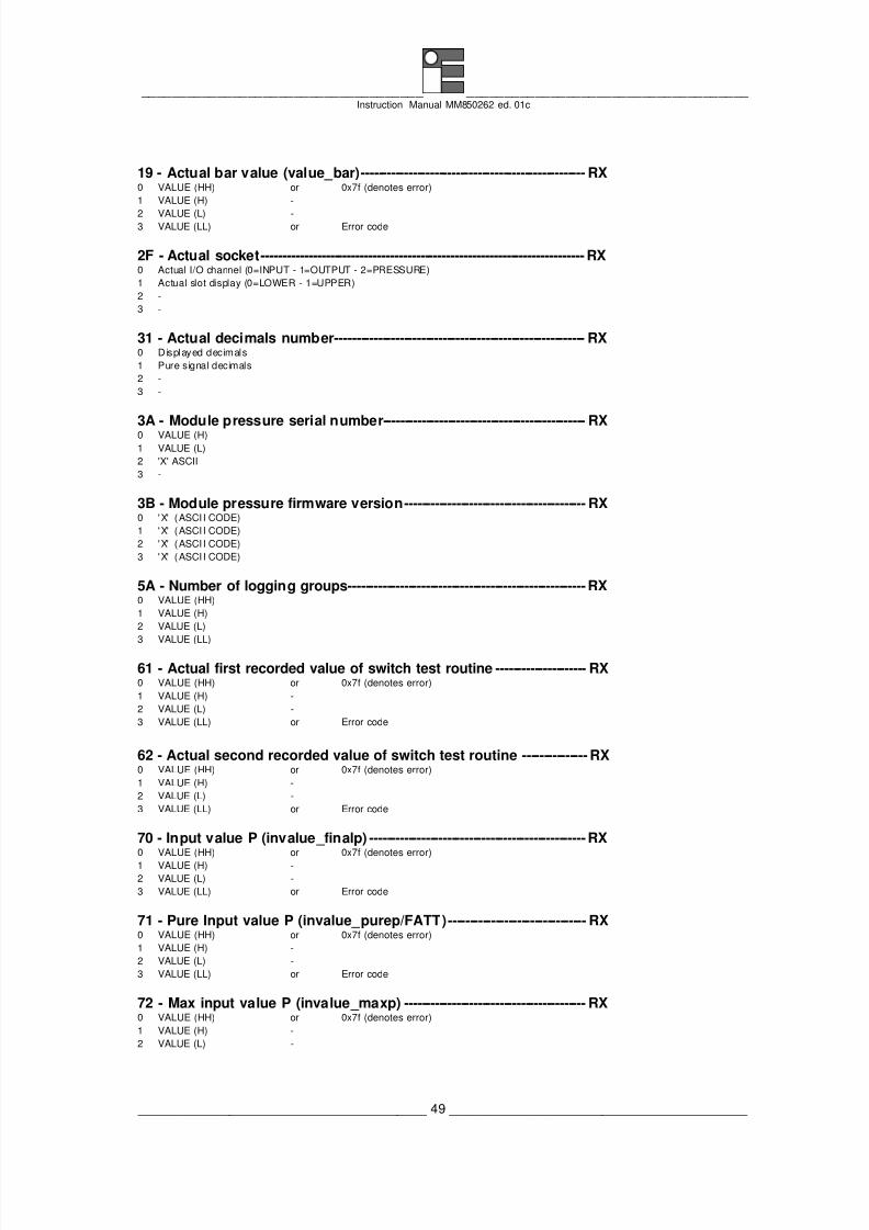
8/3/2019 MM850262-1c MCal PM200
http://slidepdf.com/reader/full/mm850262-1c-mcal-pm200 49/66
_____________________________________ _____________________________________ Instruction Manual MM850262 ed. 01c
______________________________________ 49 _______________________________________
19 - Actual bar value (value_bar)---------------------------------------------------- RX0 VALUE (HH) or 0x7f (denotes error)
1 VALUE (H) -
2 VALUE (L) -3 VALUE (LL) or Error code
2F - Actual socket--------------------------------------------------------------------------- RX0 Actual I/O channel (0=INPUT - 1=OUTPUT - 2=PRESSURE)
1 Actual slot display (0=LOWER - 1=UPPER)
2 -
3 -
31 - Actual decimals number---------------------------------------------------------- RX0 Displayed decimals
1 Pure signal decimals
2 -
3 -
3A - Module pressure serial number----------------------------------------------- RX0 VALUE (H)
1 VALUE (L)
2 'X' ASCII
3 -
3B - Module pressure firmware version------------------------------------------ RX0 'X' (ASCII CODE)
1 'X' (ASCII CODE)
2 'X' (ASCII CODE)
3 'X' (ASCII CODE)
5A - Number of logging groups-------------------------------------------------------RX0 VALUE (HH)
1 VALUE (H)
2 VALUE (L)
3 VALUE (LL)
61 - Actual first recorded value of switch test routine --------------------- RX0 VALUE (HH) or 0x7f (denotes error)
1 VALUE (H) -
2 VALUE (L) -
3 VALUE (LL) or Error code
62 - Actual second recorded value of switch test routine --------------- RX0 VALUE (HH) or 0x7f (denotes error)
1 VALUE (H) -
2 VALUE (L) -
3 VALUE (LL) or Error code
70 - Input value P (invalue_finalp) --------------------------------------------------RX0 VALUE (HH) or 0x7f (denotes error)
1 VALUE (H) -
2 VALUE (L) -
3 VALUE (LL) or Error code
71 - Pure Input value P (invalue_purep/FATT)-------------------------------- RX0 VALUE (HH) or 0x7f (denotes error)
1 VALUE (H) -
2 VALUE (L) -
3 VALUE (LL) or Error code
72 - Max input value P (invalue_maxp) ------------------------------------------ RX0 VALUE (HH) or 0x7f (denotes error)
1 VALUE (H) -
2 VALUE (L) -
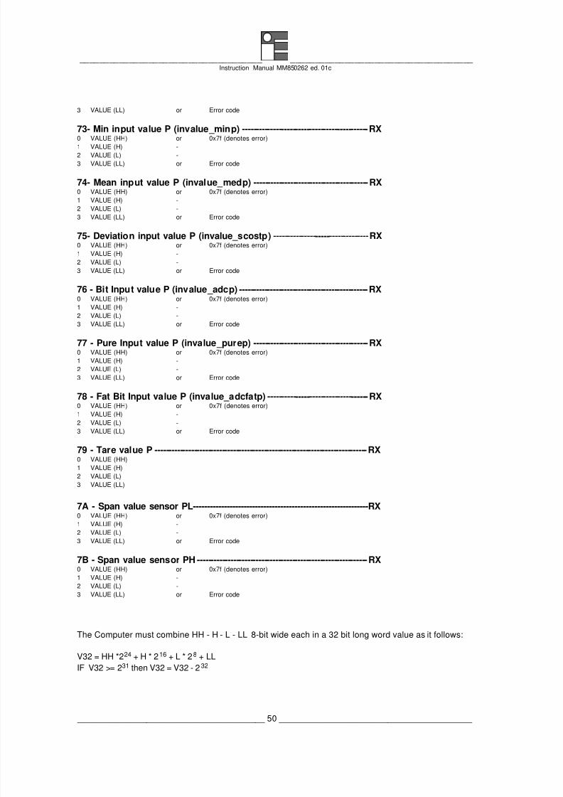
8/3/2019 MM850262-1c MCal PM200
http://slidepdf.com/reader/full/mm850262-1c-mcal-pm200 50/66
_____________________________________ _____________________________________ Instruction Manual MM850262 ed. 01c
______________________________________ 50 _______________________________________
3 VALUE (LL) or Error code
73- Min input value P (invalue_minp) ---------------------------------------------RX0 VALUE (HH) or 0x7f (denotes error)1 VALUE (H) -
2 VALUE (L) -
3 VALUE (LL) or Error code
74- Mean input value P (invalue_medp) -----------------------------------------RX0 VALUE (HH) or 0x7f (denotes error)
1 VALUE (H) -
2 VALUE (L) -
3 VALUE (LL) or Error code
75- Deviation input value P (invalue_scostp) ----------------------------------RX0 VALUE (HH) or 0x7f (denotes error)
1 VALUE (H) -
2 VALUE (L) -
3 VALUE (LL) or Error code
76 - Bit Input value P (invalue_adcp) ----------------------------------------------RX0 VALUE (HH) or 0x7f (denotes error)
1 VALUE (H) -
2 VALUE (L) -
3 VALUE (LL) or Error code
77 - Pure Input value P (invalue_purep) -----------------------------------------RX0 VALUE (HH) or 0x7f (denotes error)
1 VALUE (H) -
2 VALUE (L) -
3 VALUE (LL) or Error code
78 - Fat Bit Input value P (invalue_adcfatp) ------------------------------------RX0 VALUE (HH) or 0x7f (denotes error)
1 VALUE (H) -
2 VALUE (L) -
3 VALUE (LL) or Error code
79 - Tare value P ----------------------------------------------------------------------------RX0 VALUE (HH)
1 VALUE (H)
2 VALUE (L)
3 VALUE (LL)
7A - Span value sensor PL--------------------------------------------------------------RX0 VALUE (HH) or 0x7f (denotes error)
1 VALUE (H) -
2 VALUE (L) -
3 VALUE (LL) or Error code
7B - Span value sensor PH -------------------------------------------------------------RX0 VALUE (HH) or 0x7f (denotes error)
1 VALUE (H) -
2 VALUE (L) -
3 VALUE (LL) or Error code
The Computer must combine HH - H - L - LL 8-bit wide each in a 32 bit long word value as it follows:
V32 = HH *224 + H * 216 + L * 28 + LL
IF V32 >= 231 then V32 = V32 - 2 32

8/3/2019 MM850262-1c MCal PM200
http://slidepdf.com/reader/full/mm850262-1c-mcal-pm200 51/66
_____________________________________ _____________________________________ Instruction Manual MM850262 ed. 01c
______________________________________ 51 _______________________________________
or the H and L 8-bit wide each in a 16-bit word value as it fol lows:
V16 = H * 28 + L
IF V16 >= 215 then V16 = V16 - 216
I/O TYPE o CNV TYPE 11 = PL% 22 = Pext
12 = PH% 23 = PL-PH
13 = Pext% 24 = PH-PL
14 = PL%- PH% 25 = Pext-PL
15 = PH%- PL% 26 = PL-Pext
16 = Pext%- PL% 27 = Pext-PH
17 = PL%-Pext% 28 = PH-Pext
18 = Pext%- PH% 29 = X Scaling
19 = PH%- Pext%
20 = PL
21 = PH
I/O FLAGS_IO (InP channel)
(FLAGS_IO) .AND. 3 1 0 = mbar
1 = bar2 = Pascal
3 = hPascal
(FLAGS_IO) .AND. &E0 0 = Pext ID#1 2 = Pext ID#3 4 = Pext ID#5
1 = Pext ID#2 3 = Pext ID#4
(FLAGS_IO) .AND. &700 0 = 0 decimals 3 = 3 decimals
1 = 1 decimals 4 = 4 decimals
2 = 2 decimals 5 = 5 decimals
IF Measure (HH) or 0 = None
Inp CNV (HH) or 1 = Overrange
Max (HH) or 2 = Underrange
Min (HH) or 5 = Calc. err.
Med (HH) or 6 = ******
Dev (HH) or 7 = Overflow
Bar (HH) = 7F (HEX) then the 8 = Underflow
corresponding value LL represent the error 9 = Measure waiting
code: 14 = Zero err.
(Also for errout_global) 17 = No Avail
18 = Com. err.
19 = No module
20 = No active
21 = T High
22 = T Low
23 = PH fail
24 = PL prot.
"X" represents the ASCII code of the MicroCal 200 PCcorresponding character, for the following
characters, you must apply the conversion 128<--------------------->248
table, as shown: 129<--------------------->234
130<--------------------->230
131<--------------------->24
132<--------------------->25
133<--------------------->224

8/3/2019 MM850262-1c MCal PM200
http://slidepdf.com/reader/full/mm850262-1c-mcal-pm200 52/66
_____________________________________ _____________________________________ Instruction Manual MM850262 ed. 01c
______________________________________ 52 _______________________________________
(FLAGS_X).AND. 7 (0 - 5) = x scaling decimals
(FLAGS_X).AND. 8 0 = Linear
1 = Square
(FLAGS_X).AND. & 100 (0 - 6) = Pext ID#n
V bat must be divided by 100 and represents the battery voltage with 2 decimals.
YEAR represents the year between 00-99.
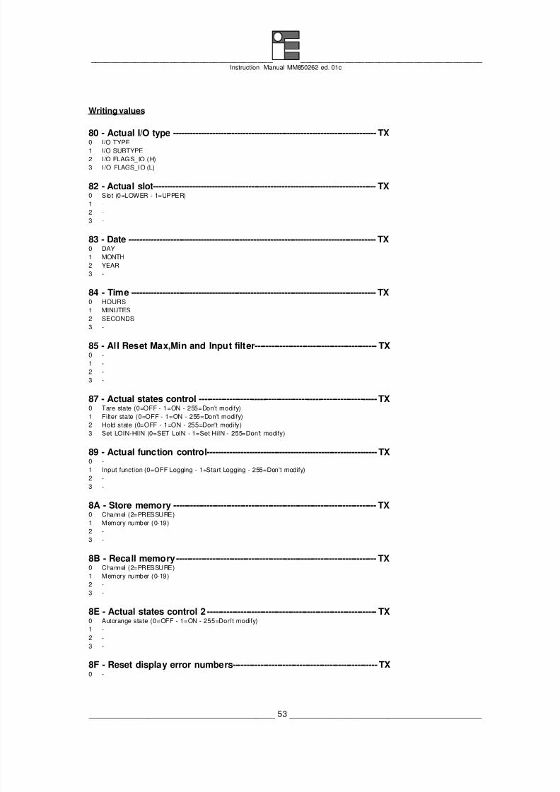
8/3/2019 MM850262-1c MCal PM200
http://slidepdf.com/reader/full/mm850262-1c-mcal-pm200 53/66
_____________________________________ _____________________________________ Instruction Manual MM850262 ed. 01c
______________________________________ 53 _______________________________________
Writing values
80 - Actual I/O type ------------------------------------------------------------------------- TX0 I/O TYPE
1 I/O SUBTYPE
2 I/O FLAGS_IO (H)
3 I /O FLAGS_IO (L)
82 - Actual slot-------------------------------------------------------------------------------- TX0 Slot (0=LOWER - 1=UPPER)
1 -
2 -
3 -
83 - Date ----------------------------------------------------------------------------------------- TX0 DAY
1 MONTH
2 YEAR
3 -
84 - Time ---------------------------------------------------------------------------------------- TX0 HOURS
1 MINUTES
2 SECONDS
3 -
85 - All Reset Max,Min and Input filter-------------------------------------------- TX0 -
1 -
2 -
3 -
87 - Actual states control ----------------------------------------------------------------TX0 Tare state (0=OFF - 1=ON - 255=Don't modify)
1 Filter state (0=OFF - 1=ON - 255=Don't modify)2 Hold state (0=OFF - 1=ON - 255=Don't modify)
3 Set LOIN-HIIN (0=SET LoIN - 1=Set HiIN - 255=Don't modify)
89 - Actual function control------------------------------------------------------------- TX0 -
1 Input function (0=OFF Logging - 1=Start Logging - 255=Don't modify)
2 -
3 -
8A - Store memory ------------------------------------------------------------------------- TX0 Channel (2=PRESSURE)
1 Memory number (0-19)
2 -
3 -
8B - Recall memory------------------------------------------------------------------------ TX0 Channel (2=PRESSURE)
1 Memory number (0-19)
2 -
3 -
8E - Actual states control 2 ------------------------------------------------------------- TX0 Autorange state (0=OFF - 1=ON - 255=Don't modify)
1 -
2 -
3 -
8F - Reset display error numbers----------------------------------------------------TX0 -

8/3/2019 MM850262-1c MCal PM200
http://slidepdf.com/reader/full/mm850262-1c-mcal-pm200 54/66
_____________________________________ _____________________________________ Instruction Manual MM850262 ed. 01c
______________________________________ 54 _______________________________________
1 -
2 -
3 -
9F - Actual reset recorded values of switch test routine -----------------TX0 -
1 -
2 -
3 -
C3 - Filter weight input Pressure ----------------------------------------------------TX0 Filter weight (1-255)
1 -
2 -
3 -
C5 - Scroll/Swap selecting--------------------------------------------------------------TX0 mode (0=SWAP - 1=SCROLL)
1 -
2 -
3 -
F4 - Set baud rate by instrument table -------------------------------------------TX0 VALUE (0=Off,1=300,2=600,3=1200,4=2400,5=4800,6=9600,7=19200,8=38400,9=57600,10=115200)
1 -
2 -
3 -
F5 - Set baud rate directly --------------------------------------------------------------TX0 VALUE (HH)
1 VALUE (H)
2 VALUE (L)
3 VALUE (LL)
The computer must split a 32 bit long word into 4 bytes of 8 bit as it follows:
Bits 31-24 --> HH
Bits 23-16 --> H
Bits 15-8 --> L
Bits 7-0 --> LL
TARE 0 = Off Tare
1 = On Tare
255 = Don't modify
AVG 0 = Off
1 = On
255 = Don't modify
HOLD 0 = Off
1 = On
255 = Don't modify
XSCAL 0 = Set the Low value as the actual value on the display in
INPUT mode
1 = Set the High value as the actual value on the display in
INPUT mode
255 = Don't modify

8/3/2019 MM850262-1c MCal PM200
http://slidepdf.com/reader/full/mm850262-1c-mcal-pm200 55/66
_____________________________________ _____________________________________ Instruction Manual MM850262 ed. 01c
______________________________________ 55 _______________________________________
FUN Input 0 = Off Logging
1 = Start Logging
255 = Don't modify
MEM Represents the memory number between 0÷19
CHN 0 = Store to OUT memories
1 = Store to IN memories

8/3/2019 MM850262-1c MCal PM200
http://slidepdf.com/reader/full/mm850262-1c-mcal-pm200 56/66
_____________________________________ _____________________________________ Instruction Manual MM850262 ed. 01c
______________________________________ 56 _______________________________________
11 MAINTENANCE
The MicroCal PM200 portable calibrator system has been factory tested and calibrated before
shipment.
The calibration should be verified and re-adjusted if the instrument shows an error exceeding the
declared specifications or when a critical active or passive component is replaced (either at component
level or at board level)
Eurotron will supply, on request, a technical reference manual, with all instructions and
recommendations for service and calibration.
Eurotron engineers will give prompt support for any assistance request .
11.1 Faulty operating conditions
During the start up, measuring and simulation modes, faulty conditions of the instrument will be
announced, with coded messages.
All errors which cannot be recovered without the user's knowledge, result in some system action to
inform the operator via a message, and where possible the system is restored.
Errors are classified thanks to the method by which they are handled. Recoverable errors report the
error and then continue.
System errors which cannot be recovered cause the system to halt with a message displayed.
Restarting the instrument from -Power ON- may clear the error, but generally such messages are
caused by hardware or software faults, which require the user’s action.
After the start up diagnostic routine the presence of a fault in the system will be announced as it follows:
"Overrange" Indicates an input signal higher than the acceptable level.
Indicates an output signal setting higher than the acceptable level.
"Underrange" Indicates a negative input signal lower than the acceptable one.
Indicates an output negative signal setting lower than the acceptable
limit.
"Calc.err." Possible error during scale factor computation
"Overflw" Indicates "overflow" conditions
"Underflw" Indicates "underflow" conditions
"******" Indicates that Max, Min or Med values are meaningless.
(measure wait) This error number indicates that the measured circuit has been
temporary halted.
"Zero err" Indicates that the internal autozero is out of range.
"PS Fail" Indicates that the external load is too low during the current loop
measurement.
"No modul" Indicates that the pressure module is not connected.

8/3/2019 MM850262-1c MCal PM200
http://slidepdf.com/reader/full/mm850262-1c-mcal-pm200 57/66
_____________________________________ _____________________________________ Instruction Manual MM850262 ed. 01c
______________________________________ 57 _______________________________________
"No avail" The operator is trying to use a sensor without the linearization table
loaded into the memory of the pressure module.
"Com. err" Indicates that the pressure module does not communicate with the
calibrator module correctly.
"No activ" Indicates that the pressure sensor is not active.
"T (high)","T (low)" Indicates that the sensor temperature exceeds the compensation limits.
"PH fail" Indicates that the PH sensor could be damaged and, for this reason, it
is not possible switching to the PL sensor.
"PL prot" Indicates that the automatic PL protection is activated.
11.2 ProtectionsAn intermittence sound signals to the operator that the pressure is near to the acceptable limits of the
internal sensors in the pressure module. Same protection are operator’s disable and the following
paragraph shows the three type of protections.
11.2.1 Logical protections
The following logical protections are activate when the instrument is switched on and the operator, if it
is necessary, can disactivate them (see par. 7.10).
• PL sensor automatic protection (PL prot.):
− Absolute and gauge measurements: When the PL sensor measure a 105% f.s. pressure value,the system disconnect the sensor input from the test circuit. If the autorange function is not
active, an "Overrng" message will appear on the display. If the PH sensor is installed, it measure
the pressure circuit value anyway. When the actual pressure, measured with the PH sensor,
returns inside the PL limits, the system reconnects the PL to the pneumatic circuit. If an
inconsistance between the PL and the PH measurement happens (eg. a PH sensor damage), a
"PL prot" error message will appear. Instead, if the autorange function is active, the system
switch automatically to PH measurements.
− Differential measurements: When the PL sensor measure a 105% f.s. pressure value, the
system open the electrovalve to discharge the pressure from the test circuit to protect the sensor.
• Testing components protection:
− Pressure generator: If the built-in hand pump is installed, the Pressure Module is able to
activate an automatic safety function for automatically block the pumping action at the desired set
pressure. This function is useful to preserve the pressure transducer to be calibrated from
overpressure.
The following table shows the possible protection and the activating order in the different using
condition:
Sensor Generation MeasureAutorange Buzzer, change sensor, pump
blocking, secure valve
Buzzer, change sensor, secure
valve
PL Buzzer, PL prot., pump blocking, Buzzer, PL prot., secure valve

8/3/2019 MM850262-1c MCal PM200
http://slidepdf.com/reader/full/mm850262-1c-mcal-pm200 58/66
_____________________________________ _____________________________________ Instruction Manual MM850262 ed. 01c
______________________________________ 58 _______________________________________
secure valve
PH Buzzer, pump blocking, secure valve Buzzer, secure valve
∆P PL Buzzer, PL prot., secure valve
PH Buzzer, secure valve
11.2.2 Electronic protections
The system is protected from electrical damages by self limiting circuits and fuse as it follows :
• For MicroCal 200 and MicroCal 200+ protections please refer to MicroCal 200 instruction manual
(cod. MM850216).
• Some auto-safe fuses, to protect the module from short circuit damages (current loop power supply)
and from overcurrent (mA input channel), are inserted into the pressure module .
• The 24 Vdc power supply is protected by a self limiting circuit to prevent an output current higher than
25 mA.
11.2.3 Pneumatic protections
The system is protected against overpressure damages as it follows :
• Two overpressure valves are programmed in factory to preserve the sensors. The valves are set to
became active at 125% of the sensor full scale. It is possible to restore the valves discharging the
circuit to atmospheric pressure.
11.3 Recommendations
11.3.1 General recommendations
The total volume of the test circuit must be necessarily kept as small as possible ; as a consequence
also small variations of the circuit volume bring about immediate in pressure variations.
Ideally, the parts of the pneumatic circuit shouldn't modify their volume when a variation of the
temperature or of the pressure occur. Otherwise, continuous adjustments will be necessary.
The most critical component of the test circuit is the PVC flexible pipe that, if not carefully selected, may
undergo great volume variations for its intrinsic elastic property. It is advisable to use PVC flexible pipes
with thick-wall (6x4mm) or Rilsan rigid pipes with 6x2mm wall to prevent the above listed problems.
The same flexible pipe must be used for what is left of the pneumatic circuit. Don't use low cost or thin-
wall PVC or plastic pipes .
If you don't consider the above recommendations, you should take into consideration volume variations
in the circuit and the consequent necessity of pressure adjustment to keep it at the desired valve.
11.3.2 Safety recommendations
• Do NOT use liquid. Use only air or non-reducing and non-oxidant gases as pressure media.
Different fluids could serious damage the pneumatic components and the internal sensors.
• Do NOT use explosive gases.
• Use ONLY the auto blocking conectors to open the pressurised circuit.
• Insert the fluid outlet tube in the "Ventilation Output" connector on the pressure module ; otherwise
the secure valves and the fluid outlet will not be active.
• Pay attention using the sysstem with pressure value higher than 10 bar. Breaked pipes,
disconnected pressure connectors can produce injuries to the personnel. Make test circuit as short

8/3/2019 MM850262-1c MCal PM200
http://slidepdf.com/reader/full/mm850262-1c-mcal-pm200 59/66
_____________________________________ _____________________________________ Instruction Manual MM850262 ed. 01c
______________________________________ 59 _______________________________________
as possible and use only adequate materials. If it is used an external pressure sensor, install it
directly into the plant. Do NOT use extension pipes.
• Don't apply a pressure higher than 125% full scale to the calibrator. If an excessive pressure, higher
than the stated one, is applied, personnel may receive injuries that could, in extreme circumstances
be lethal. Furthermore, possible serious damages can occur to the instrument, the user’s system
and equipment.
• The pressure module is protected through safety valves from overpressure. It is possible to restore
the valves discharging the circuit to atmospheric pressure. Their action do not exclude absolutely
possible damage of the module and its components.
• The internal hand pump is able to generate pressure up to 20 bar without considering the external
components connected to it: take care using it.
11.5 Storage
If the instrument has been left unused for a long time, it is recommended to remove its batteries.
Store the instrument in the original package, at a temperature from -30°C to +60°C, with R.H. less than90%.
If the instrument has been unused for a month check the battery voltage, and charge Ni-Cd batteries for
at least 4 hours.
11.6 Spare parts & Accessories
F3280004 External 10 bar (150 PSI) cylinder type pump
F3280005 External -0.8 bar (-10 PSI) cylinder type pump
F3280001 External 14 bar (210 PSI) pliers type pump
F3280003 External 2 bar (30 PSI) pliers type pump
F3280002 External 20 bar (300 PSI) pliers type pump
F3280008 External 350 bar (5000 PSI) oil pumpF3280009 External 700 bar (10000 PSI) oil pump
EE170067 n.1 1/8" BSPM
EE170069 n.1 1/4" BSPM
EE170068 n.1 1/8" NPTM
EE170070 n.1 1/4" NPTM
EE300040 Electrical signal test lead kit
EE170066 Rilsan tube holder
EE370048 2m Rilsan tube F6/4 mm
BB260097 CalpMan software for PC
BB260096 LinMan software for PC
BB260095 LogMan software for PC
BB530004 TTL/RS232 isolated adapter
BB490000 External impact printerEE420197 1m length cable + 12 pin connector for external customer sensors (mA/V)
EE420198 5m length extension cable for any external sensor
BB880033 Accessory carrier cover for leather case
EE300057 19” standard rack adapter kit
EE420199 Pressostat test lead kit
EE830050 External sensor 35 bar (500 PSI) (Gauge) 316SS
EE830051 External sensor 70 bar (1000 PSI) (Gauge) 316SS
EE830052 External sensor 150 bar (2000 PSI) (Gauge) 316SS
EE830053 External sensor 350 bar (5000 PSI) (Gauge) 316SS
EE830054 External sensor 700 bar (10000 PSI) (Gauge) 316SS

8/3/2019 MM850262-1c MCal PM200
http://slidepdf.com/reader/full/mm850262-1c-mcal-pm200 60/66
_____________________________________ _____________________________________ Instruction Manual MM850262 ed. 01c
______________________________________ 60 _______________________________________

8/3/2019 MM850262-1c MCal PM200
http://slidepdf.com/reader/full/mm850262-1c-mcal-pm200 61/66
_____________________________________ _____________________________________ Instruction Manual MM850262 ed. 01c
______________________________________ 61 _______________________________________
12 CERTIFICATES
12.1 Warranty terms
Each instrument is shipped with a Warranty Certificate that indicates the validity conditions of the
warranty itself.
Eurotron Instruments warrants its products against defects in materials and workmanship.
Any misuse, abuse, or non Eurotron Instruments authorized alterations, modifications and/or repairs to
Eurotron Instruments products will void the warranty. If you discover a defect, Eurotron Instruments will,
repair or replace the product, provided you return the product during the warranty period, transportation
prepaid, to Eurotron Instruments.
This warranty applies to the original purchaser only.
Please include a copy of the original invoice or a small service charge may be applied.
Prior to returning the product for warranty consideration, call Eurotron Instruments Technical Support for
a returned material authorization number and shipping instructions.
12.2 Letter of conformity
Each instrument is shipped with a Letter of Conformity, to grant that the characteristics of the instrument
correspond to the required ones, and that the instrument calibration is traceable to the National and
International Standards.

8/3/2019 MM850262-1c MCal PM200
http://slidepdf.com/reader/full/mm850262-1c-mcal-pm200 62/66
_____________________________________ _____________________________________ Instruction Manual MM850262 ed. 01c
______________________________________ 62 _______________________________________
APPENDIX

8/3/2019 MM850262-1c MCal PM200
http://slidepdf.com/reader/full/mm850262-1c-mcal-pm200 63/66
_____________________________________ _____________________________________ Instruction Manual MM850262 ed. 01c
______________________________________ 63 _______________________________________
A1 EMC Conformity
The Pressure Module case is made in aluminium to fulfil the prevision of the directive 89/336/CEE
Electromagnetic Compatibility.
The following page is a copy of the EMC declaration of conformity.

8/3/2019 MM850262-1c MCal PM200
http://slidepdf.com/reader/full/mm850262-1c-mcal-pm200 64/66
_____________________________________ _____________________________________ Instruction Manual MM850262 ed. 01c
______________________________________ 64 _______________________________________
Declaration of Conformity
We : Eurotron Instruments S.p.A.(Supplier's name)
Viale F.lli Casiraghi 409/413 - 20099 Sesto S. Giovanni (MI) - Italy(Address)
declare under our sole responsibility that the product :
Portable multifunction calibrator type MicroCal PM200 System(Name and type)
cat. 3222(Model)
to which this declaration relates is in conformity with thefollowing normative documents :
EN 50082-2 (3/95)IEC 1000-4-2 / IEC 1000-4-4 / IEC 1000-4-11ENV 50140 - ENV 50141 - ENV 50204
EN 55011(Title, number and date of issue of normative documents)
following the prevision of directive :
89/336/CEE Electromagnetic Compatibility (EMC)
Sesto S. Giovanni, January 08th, 1996
(Place and date of issue) (Signature of authorized person)
eurotron
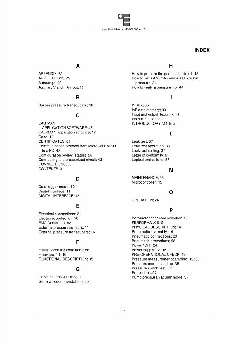
8/3/2019 MM850262-1c MCal PM200
http://slidepdf.com/reader/full/mm850262-1c-mcal-pm200 65/66
_____________________________________ _____________________________________ Instruction Manual MM850262 ed. 01c
______________________________________ 65 _______________________________________
INDEX
AAPPENDIX; 62
APPLICATIONS; 43
Autorange; 28
Auxiliary V and mA input; 16
BBuilt-in pressure transducers; 16
CCALPMAN
APPLICATION SOFTWARE; 47
CALPMAN application software; 12
Case; 13
CERTIFICATES; 61
Communication protocol from MicroCal PM200
to a PC; 48
Configuration review (status); 26
Connecting to a pressurized circuit; 43
CONNECTIONS; 20
CONTENTS; 3
DData logger mode; 12
Digital interface; 11
DIGITAL INTERFACE; 48
EElectrical connections; 21
Electronic protection; 58
EMC Conformity; 63
External pressure sensors; 11
External pressure transducers; 16
FFaulty operating conditions; 56
Firmware; 11; 16
FUNCTIONAL DESCRIPTION; 15
GGENERAL FEATURES; 11
General recommendations; 58
HHow to prepare the pneumatic circuit; 43
How to set a 4/20mA sensor as External
pressure; 31
How to verify a pressure Trx; 44
IINDEX; 65
InP data memory; 33
Input and output flexibility; 11
Instrument codes; 9INTRODUCTORY NOTE; 2
LLeak test; 37
Leak test operation; 38
Leak test setting; 37
Letter of conformity; 61
Logical protections; 57
MMAINTENANCE; 56
Microcontroller; 15
OOPERATION; 24
PParameter or sensor selection; 28
PERFORMANCE; 5
PHYSICAL DESCRIPTION; 14
Pneumatic assembly; 16
Pneumatic connections; 20
Pneumatic protections; 58Power "ON"; 24
Power supply; 13; 15
PRE-OPERATIONAL CHECK; 19
Pressure measurement damping; 12; 33
Pressure module setting; 35
Pressure switch test; 34
Protections; 57
Pump pressure/vacuum mode; 37

8/3/2019 MM850262-1c MCal PM200
http://slidepdf.com/reader/full/mm850262-1c-mcal-pm200 66/66
_____________________________________ _____________________________________ Instruction Manual MM850262 ed. 01c
RRecommendations; 58
Report of calibration; 13
SSafety recommendations; 58
Scale factor configuration; 29
Scale factor function; 12
Sensor configuration; 28
Slot display scrolling; 26
Slot display swapping; 25
Spare parts & Accessories; 59
Specifications; 7
Square root function; 12
Storage; 59
UUsing the built-in hand pump; 43
WWarranty terms; 61
ZZero function; 36