mmaaggnneettiicc lleevveell ggaauuggee ttyyppee...
TRANSCRIPT
www.houdec.com
MMaaggnneettiicc lleevveell ggaauuggee
TTyyppee 881100
Technical manual 50466-604 May 2014


Magnetic level gauges
Technical manual 810-F
January 2006
Page 0
SUMMARY Page
General description Design / Regulation
1
General description of the unit Technical Codification of the unit
2
Construction standard 3 - 6
Construction High Pressure 7 -16
Visualization system 17 -19
Side connections 20 -23
Upper connection 24
Lower Connection 25
Range of Floats 26-30
Options
Switch 31-32
Transmitters 33-37
Construction Version PVC / PVDF / PPH 38
Documentation 39

Technical manual 810-F January 2006 Magnetic level gauges
Page 1
Type 810 General description The magnetic level gauge type 810 enables the direct reading of the levels of either aggressive or dangerous liquids in tanks, in the open air or under pressure. Based on its construction, this device ensures a good accuracy, excellent reliability and greater safety of use. A float fitted with a magnetic core follows the variations in the level to be measured.
Version with slider (810S) the float causes a magnetic index which slides in a Pyrex tube located along a graduated
scale.
Version with rollers (810R) the float commands on its way the swing of two-tone magnetically locked rollers
(polyamide). The red zone (continuous band) indicates the level in the tank.
Version with flaps (810VA) the float commands on its way the swing of two-tone magnetically locked flaps
(aluminum). The red zone (continuous band) indicates the level in the tank.
Example of operation type 810
Design / Regulation
Two design codes are applicable to the design of level gauges type 810: -The French code said: CODAP -The American code said: ASME VIII The devices of type 810 are French manufactured and controlled in our workshops according to the ISO 9001, 2008 version In some cases, the design of level gauges type 810 may be subject to the Pressure Equipment Directive of 97/23/EC (PED) Depending on the options selected, these may being subject to certain regulations (Atex, CSA, ...)

Magnetic level gauges
Technical manual 810-F
January 2006
Page 2
Type 810 General description of the gauge
Example:
810 – R – 25 – C30 – M1/2 - T1– S1x1 – Z4 - D12 – 500 – CATII I I I I I I I I I I I I
Type of construction
Reading System
DN Type of
construction
Type of float
Type of transmitter
Types of Switch x qty
Options Documentation, certificates
Center to center
(mm)
PED category
If applicable
See page 3-16 See page
17-19 See page 20-23 See page
26-30 See page 33-37 See page 31-32
See page 24-25
See page 39
article 3§3 CATI CATII CATIII CATIV (Inspection
ON)
Continuous measurement 4-20 mA transmitter for transmission over long distances. Available in standard version, S. I, ADF ATEX.
Process connections According to NF IN1092-1 NF EN 1759-1 ANSI B16-5 BW-NPT-SW Other connections on requests
Alarm Switch Adjustable mounting on the chamber of the device through stainless steel brackets. Available in standard version IP65, S. I. or ADF ATEX.
Float Equipped with magnets on 360°, it monitors the variations of the liquid inside of the chamber. (Stainless Steel/Titanium as standard according to client specifications) Possible interface measure
Blind flange+drain Allows you to ensure the maintenance of the appliance. Several available options
Reading system S= Slider R= Rollers VA= Aluminum Flaps Without visualization: Continuous measurement (MC1000)
Chamber of float Also known as the body. It is composed of a vertical anti-magnetic tube (stainless steel as standard) Welded (with TIG process) to a connecting process for a side/side mounting as standard
Vent + plug 1/2″NPT Allows you to perform the ventilation. Several available options
Manufacturer Plate The manufacturer's rating plate stipulating the essential technical data according to the applicable guidelines and standards. In stainless steel riveted French/ English.
Assembling Through airtight seam process TIG carried out by a qualified welder EN / ASME IX
Chamber of float Exotic materials on request

www.houdec.com
Type 810 Stainless Steel Constructions 304 L
Standard Version
Stainless steel 304 L code C3 to C5
Chamber Material: 304 L
Ø 60.3 mm x 2 mm rolled welded
Connection Side-side DN 15 to 50 (1/2" to 2 ")
C3 C4 C5
304 L PN 10 / PN16 / PN40 Flange (to specify) according to EN 1092-1 304 L PN20 Flange Type B according to EN 1759-1 (ANSI 150 Lbs) 304 L PN50 Flange type B according to 1759-1 (ANSI 300 Lbs)
See connections specifications page 20
Center distance Minimum: E= 300 mm
Maximum: E= 5500 mm
Beyond: on request (device in several sections)
Float Stainless Steel
Titanium
See floats' specifications pages 26 to 30
Indication R - Polyamide Rollers (PA6V) White/Red
VA - Aluminum Flaps White/Red
S - Magnetic Slider
Indication of sank float (Blue Flaps/Rollers) See indicator specifications page 17-19
Upper Part Welded bottom 304L
Other available options -see page 24
Lower Part Flange type 11B (Welding neck) -PN according to building code
Purge + plug ½" NPT
Other available options -see page 25
Options
Switch See Switch specifications pages 31-32
Transmitter See transmitters specifications pages 33 to 37
Scales Stainless steel 304L (Graduated)
Other available options -see page 19
Service conditions Temperature -160°C to +350°C
Pressure Atm to limit PN of the flange according to applicable Standard
Density From 0.52 kg/m 3
Interface measurement as option
Dimension change
with float dimension
Magnetic level gauge Technical manual
50466-604
- 4 -
Type 810 Stainless Steel Constructions 304L
Standard Version
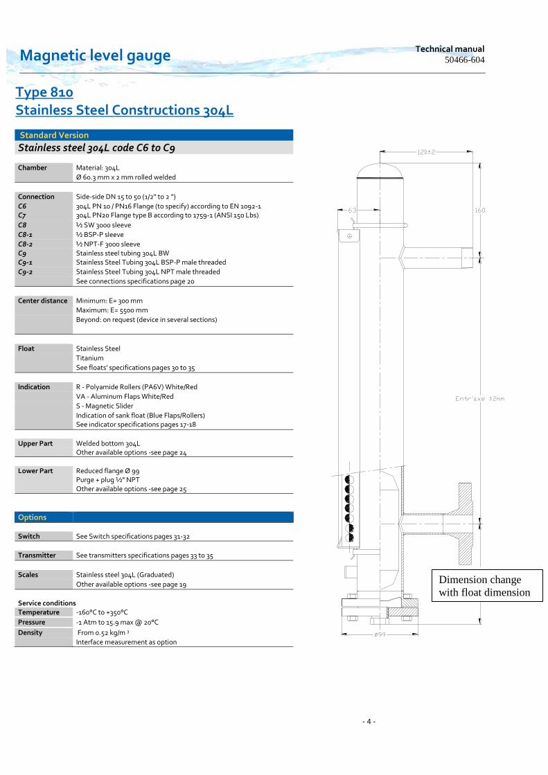
Stainless steel 304L code C6 to C9
Chamber Material: 304L
Ø 60.3 mm x 2 mm rolled welded
Connection Side-side DN 15 to 50 (1/2" to 2 ")
C6 C7
304L PN 10 / PN16 Flange (to specify) according to EN 1092-1 304L PN20 Flange type B according to 1759-1 (ANSI 150 Lbs)
C8 ½ SW 3000 sleeve
C8-1 ½ BSP-P sleeve
C8-2 ½ NPT-F 3000 sleeve C9 Stainless steel tubing 304L BW C9-1 Stainless Steel Tubing 304L BSP-P male threaded
C9-2 Stainless Steel Tubing 304L NPT male threaded
See connections specifications page 20
Center distance Minimum: E= 300 mm
Maximum: E= 5500 mm
Beyond: on request (device in several sections)
Float Stainless Steel
Titanium
See floats' specifications pages 30 to 35
Indication R - Polyamide Rollers (PA6V) White/Red
VA - Aluminum Flaps White/Red
S - Magnetic Slider
Indication of sank float (Blue Flaps/Rollers) See indicator specifications pages 17-18
Upper Part Welded bottom 304L Other available options -see page 24
Lower Part Reduced flange Ø 99 Purge + plug ½" NPT Other available options -see page 25
Options
Switch See Switch specifications pages 31-32
Transmitter See transmitters specifications pages 33 to 35
Scales Stainless steel 304L (Graduated)
Other available options -see page 19
Service conditions Temperature -160°C to +350°C
Pressure -1 Atm to 15.9 max @ 20°C
Density From 0.52 kg/m 3
Interface measurement as option
Dimension change
with float dimension

www.houdec.com
Type 810 Stainless Steel Constructions 316 L
Type 810
Standard Version
Stainless steel 316 L code C13 to C15
Chamber Material: 316/316 L
Ø 60.3 mm x 2 mm rolled welded
Connection Side-side DN 15 to 50 (1/2" to 2 ")
C13 C14 C15
316 L PN 10 / PN16 / PN40 Flange (to specify) according to EN 1092-1 316 L PN20 Flange Type B according to EN 1759-1 (ANSI 150 Lbs) 316 L PN50 Flange type B according to 1759-1 (ANSI 300 Lbs)
See connections specifications page 20
Center distance Minimum: E= 300 mm
Maximum: E= 5500 mm
Beyond: on request (device in several sections)
Float Stainless Steel
Titanium
See floats' specifications pages 28 to 30
Indication R - Polyamide Rollers (PA6V) White/Red
VA - Aluminum Flaps White/Red
S - Magnetic Slider
Indication of sank float (Blue Flaps/Rollers) See indicator specifications pages 17-18
Upper Part Welded bottom 316 L Other available options -see page 24
Lower Part Flange type (Welding neck) PN according to building Purge + plug ½" NPT Other available options -see page 25
Options
Switch See Switch specifications pages 31-32
Transmitter See transmitters specifications pages 33 to 35
Scales Stainless steel 304L (Graduated)
Other available options -see page 19
Service conditions Temperature -160°C to +350°C
Pressure -1 Atm to 32 max
Density From 0.52 kg/m 3
Interface measurement as option
Dimension change
with float dimension
Magnetic level gauge Technical manual
50466-604
- 6 -
Stainless Steel Constructions 316 L
Standard Version
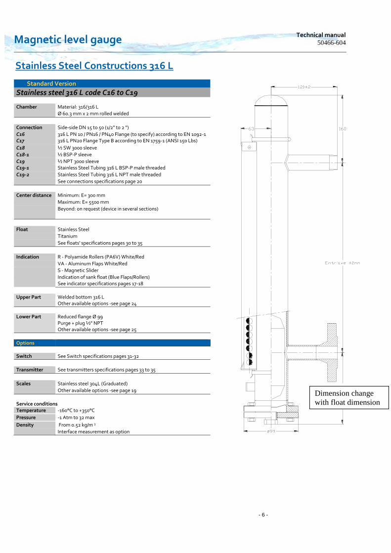
Stainless steel 316 L code C16 to C19
Chamber Material: 316/316 L
Ø 60.3 mm x 2 mm rolled welded
Connection Side-side DN 15 to 50 (1/2" to 2 ")
C16 C17
316 L PN 10 / PN16 / PN40 Flange (to specify) according to EN 1092-1 316 L PN20 Flange Type B according to EN 1759-1 (ANSI 150 Lbs)
C18 ½ SW 3000 sleeve
C18-1 ½ BSP-P sleeve
C19 ½ NPT 3000 sleeve C19-1 Stainless Steel Tubing 316 L BSP-P male threaded
C19-2 Stainless Steel Tubing 316 L NPT male threaded
See connections specifications page 20
Center distance Minimum: E= 300 mm
Maximum: E= 5500 mm
Beyond: on request (device in several sections)
Float Stainless Steel
Titanium
See floats' specifications pages 30 to 35
Indication R - Polyamide Rollers (PA6V) White/Red
VA - Aluminum Flaps White/Red
S - Magnetic Slider
Indication of sank float (Blue Flaps/Rollers) See indicator specifications pages 17-18
Upper Part Welded bottom 316 L Other available options -see page 24
Lower Part Reduced flange Ø 99 Purge + plug ½" NPT Other available options -see page 25
Options
Switch See Switch specifications pages 31-32
Transmitter See transmitters specifications pages 33 to 35
Scales Stainless steel 304L (Graduated)
Other available options -see page 19
Service conditions Temperature -160°C to +350°C
Pressure -1 Atm to 32 max
Density From 0.52 kg/m 3
Interface measurement as option
Dimension change
with float dimension

www.houdec.com
Type 810 Stainless Steel Constructions 304 L/316 L
High Pressure Version
Stainless steel 304 L/ 316 L code C20 to C22
Chamber Material: 316/316 L
Ø 60.3 mm x 2.77 mm (Sch 10)
Connection Side-side DN 15 to 50 (1/2" to 2 ")
C20 C21 C22
304L PN20 Flange according to 1759-1 (ANSI 150 Lbs) 304L PN50 Flange according to 1759-1 (ANSI 300 Lbs) 304L PN100 Flange according to 1759-1 (ANSI 600 Lbs)
See connections specifications page 21
Center distance Minimum: E= 300 mm
Maximum: E= 5500 mm
Beyond: on request (device in several sections)
Float Stainless Steel
Titanium
See floats' specifications pages 28 to 30
Indication R - Polyamide Rollers (PA6V) White/Red
VA - Aluminum Flaps White/Red
S - Magnetic Slider
Indication of sank float (Blue Flaps/Rollers) See indicator specifications page 17-18
Upper Part Sealed bottom 316 L with vent ½"NPT + Plug Other available options -see pages 24
Lower Part Flange type (Welding neck) PN according to building Purge + plug ½" NPT Assembling done by stainless steel fasteners/ door gasket
C4430 Other available options -see pages 25
Options
Switch See Switch specifications pages 31-32
Transmitter See transmitters specifications pages 33 to 35
Scales Stainless steel 304L (Graduated)
Other available options -see pages 19
Service conditions Temperature -160°C to +350°C
Pressure -1 Atm to 78 bars according to PN of the process
Density From 0.52 kg/m 3
Interface measurement as option
Documentation Technical Drawing included (D12)
Dimension change
with float dimension

Magnetic level gauge Technical manual
50466-604
- 8 -
Type 810 Stainless Steel Constructions 316 L
High Pressure Version
Stainless steel 316 L code C30/--
Chamber Material: 316/316 L
Ø 60.3 mm x 2.77 mm (Sch 10)
Connection Side-side DN 15 to 50 (1/2" to 2 ")
C30 C30/1 C30/2 C30/3
316 L PN20 Flange according to 1759-1 (ANSI 150 Lbs) ½ SW 3000 sleeve ½ NPT-F 3000 sleeve Stainless Steel Tubing 316 L NPT-M male threaded
See connections specifications page 21
Center distance Minimum: E= 300 mm
Maximum: E= 5500 mm
Beyond: on request (device in several sections)
Float Stainless Steel
Titanium
See floats' specifications pages 30 to 35
Indication R - Polyamide Rollers (PA6V) White/Red
VA - Aluminum Flaps White/Red
S - Magnetic Slider
Indication of sank float (Blue Flaps/Rollers) See indicator specifications page 17-18
Upper Part Sealed bottom 316 L with vent ½"NPT + Plug Other available options -see page 24
Lower Part Flange type (Welding neck) PN according to building Purge + plug ½" NPT Assembling done by stainless steel fasteners/ door gasket
C4430 Other available options -see page 25
Options
Switch See Switch specifications pages 31-32
Transmitter See transmitters specifications pages 33 to 35
Scales Stainless steel 304L (Graduated)
Other available options -see page 19
Service conditions
Temperature -160°C to +350°C
Pressure -1 Atm to 15.9 max
Density From 0.52 kg/m 3
Interface measurement as option
Documentation Technical Drawing included (D12)
Dimension change
with float dimension
www.houdec.com
Type 810 Stainless Steel Constructions 316 L
High Pressure Version
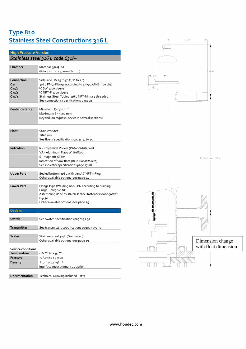
Stainless steel 316 L code C31/--
Chamber Material: 316/316 L
Ø 60.3 mm x 2.77 mm (Sch 10)
Connection Side-side DN 15 to 50 (1/2" to 2 ")
C31 C31/1 C31/2 C31/3
316 L PN50 Flange according to 1759-1 (ANSI 300 Lbs) ½ SW 3000 sleeve ½ NPT-F 3000 sleeve Stainless Steel Tubing 316 L NPT-M male threaded
See connections specifications page 21
Center distance Minimum: E= 300 mm
Maximum: E= 5500 mm
Beyond: on request (device in several sections)
Float Stainless Steel
Titanium
See floats' specifications pages 30 to 35
Indication R - Polyamide Rollers (PA6V) White/Red
VA - Aluminum Flaps White/Red
S - Magnetic Slider
Indication of sank float (Blue Flaps/Rollers) See indicator specifications page 17-18
Upper Part Sealed bottom 316 L with vent ½"NPT + Plug Other available options -see page 24
Lower Part Flange type (Welding neck) PN according to building Purge + plug ½" NPT Assembling done by stainless steel fasteners/ door gasket
C4430 Other available options -see page 25
Options
Switch See Switch specifications pages 31-32
Transmitter See transmitters specifications pages 33 to 35
Scales Stainless steel 304L (Graduated)
Other available options -see page 19
Service conditions Temperature -160°C to +350°C
Pressure -1 Atm to 40 max
Density From 0.52 kg/m 3
Interface measurement as option
Documentation Technical Drawing included (D12)
Dimension change
with float dimension
Magnetic level gauge Technical manual
50466-604
- 10 -
Type 810 Stainless Steel Constructions 316 L
High Pressure Version
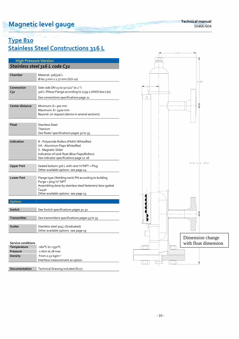
Stainless steel 316 L code C32
Chamber Material: 316/316 L
Ø 60.3 mm x 2.77 mm (Sch 10)
Connection Side-side DN 15 to 50 (1/2" to 2 ")
C32 316 L PN100 Flange according to 1759-1 (ANSI 600 Lbs)
See connections specifications page 21
Center distance Minimum: E= 300 mm
Maximum: E= 5500 mm
Beyond: on request (device in several sections)
Float Stainless Steel
Titanium
See floats' specifications pages 30 to 35
Indication R - Polyamide Rollers (PA6V) White/Red
VA - Aluminum Flaps White/Red
S - Magnetic Slider
Indication of sank float (Blue Flaps/Rollers) See indicator specifications page 17-18
Upper Part Sealed bottom 316 L with vent ½"NPT + Plug Other available options -see page 24
Lower Part Flange type (Welding neck) PN according to building Purge + plug ½" NPT Assembling done by stainless steel fasteners/ door gasket
C4430 Other available options -see page 25
Options
Switch See Switch specifications pages 31-32
Transmitter See transmitters specifications pages 33 to 35
Scales Stainless steel 304L (Graduated)
Other available options -see page 19
Service conditions Temperature -160°C to +350°C
Pressure -1 Atm to 78 max
Density From 0.52 kg/m 3
Interface measurement as option
Documentation Technical Drawing included (D12)
Dimension change
with float dimension

www.houdec.com
Type 810 Stainless Steel Constructions 316/316 L
High Pressure Version
Stainless steel 316 L code C37-C39
Chamber Material: 316/316 L
Ø 60.3 mm x 3.65 mm
Connection Side-side DN 15 to 50 (1/2" to 2 ")
C37 C39
316 PN100 Flange according to 1759-1 (ANSI 600 Lbs) 316 PN100 Flange according to 1759-1 (ANSI 900 Lbs)
See connections specifications page 22
Center distance Minimum: E= 300 mm
Maximum: E= 5500 mm
Beyond: on request (device in several sections)
Float Stainless Steel
Titanium
See floats' specifications pages 30 to 35
Indication R - Polyamide Rollers (PA6V) White/Red
VA - Aluminum Flaps White/Red
S - Magnetic Slider
Indication of sank float (Blue Flaps/Rollers) See indicator specifications page 17-18
Upper Part Sealed caps 316 L with vent ½"NPT + Plug Other available options -see page 24
Lower Part Flange (type Welding neck) PN according to building Purge + plug ½" NPT Assembling done by stainless steel fasteners/ spiral door
gasket Other available options -see page 25
Options
Switch See Switch specifications pages 31-32
Transmitter See transmitters specifications pages 36 to 39
Scales Stainless steel 304L (Graduated)
Other available options -see page 19
Service conditions Temperature -160°C to +350°C
Pressure -1 Atm to 137 bars according to PN of the process
Density From 0.52 kg/m 3
Interface measurement as option Codap and ASME Not Applicable
Documentation Technical Drawing included (D12)
Dimension change
with float dimension

Magnetic level gauge Technical manual
50466-604
- 12 -
Raccordement
Type J
Raccordement
Type J
Type 810 Stainless Steel Constructions 316/316 L
High Pressure Version
Stainless steel 316 L code C38-C40
Chamber Material: 316/316 L
Ø 60.3 mm x 3.65 mm
Connection Side-side DN 15 to 50 (1/2" to 2 ")
C38 C40
316 PN100 Flange type J according to 1759-1 (ANSI 600 Lbs) 316 PN150 Flange type J according to 1759-1 (ANSI 900 Lbs)
See connections specifications page 22
Center distance Minimum: E= 300 mm
Maximum: E= 5500 mm
Beyond: on request (device in several sections)
Float Stainless Steel
Titanium
See floats' specifications pages 28 to 30
Indication R - Polyamide Rollers (PA6V) White/Red
VA - Aluminum Flaps White/Red
S - Magnetic Slider
Indication of sank float (Blue Flaps/Rollers) See indicator specifications page 17-18
Upper Part Sealed bottom 316 L with vent ½"NPT + Plug Optional - see page 24
Lower Part Flange (type Welding neck) type J PN according to building Purge + plug ½" NPT Assembling done by stainless steel fasteners/ door gasket type J Other available options -see page 25
Option
Switch See Switch specifications pages 31-32
Transmitter See transmitters specifications pages 33 to 35
Scales Stainless steel 304L (Graduated)
Other available options -see page 19
Service conditions Temperature -160°C to +350°C
Pressure -1 Atm to 137 bars according to PN of the process
Density From 0.52 kg/m 3
Interface measurement as option
Documentation Technical Drawing included (D12)
Dimension change
with float dimension
www.houdec.com
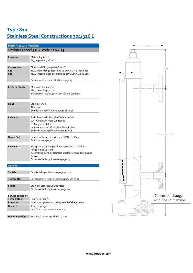
Type 810 Stainless Steel Constructions 304/316 L
High Pressure Version
Stainless steel 316 L code C26-C23
Chamber Material: 316/316 L
Ø 73.03 mm x 5.16 mm
Connection Side-side DN 15 to 50 (1/2" to 2 ")
C26 C23
304L PN50 Flange according to 1759-1 (ANSI 300 Lbs) 304L PN100 Flange according to 1759-1 (ANSI 600 Lbs)
See connections specifications page 23
Center distance Minimum: E= 300 mm
Maximum: E= 5500 mm
Beyond: on request (device in several sections)
Float Stainless Steel
Titanium
See floats' specifications pages 28 to 30
Indication R - Polyamide Rollers (PA6V) White/Red
VA - Aluminum Flaps White/Red
S - Magnetic Slider
Indication of sank float (Blue Flaps/Rollers) See indicator specifications page 17-18
Upper Part Sealed bottom 316 L with vent ½"NPT + Plug Optional - see page 24
Lower Part Flange type Welding neck PN according to building Purge + plug ½" NPT Assembling done by stainless steel fasteners/ door gasket
C4430 Other available options -see page 24
Options
Switch See Switch specifications pages 31-32
Transmitter See transmitters specifications pages 33 to 35
Scales Stainless steel 304L (Graduated)
Other available options -see page 19
Service conditions Temperature -160°C to +350°C
Pressure -1 Atm to 137 bars according to PN of the process
Density From 0.52 kg/m 3
Interface measurement as option
Documentation Technical Drawing included (D12)
Dimension change
with float dimension

Magnetic level gauge Technical manual
50466-604
- 14 -
Type 810 Stainless Steel Constructions 316 L
High Pressure Version
Stainless steel 316 L code C36-C33
Chamber Material: 316/316 L
Ø 73.03 mm x 5.16 mm
Connection Side-side DN 15 to 50 (1/2" to 2 ")
C36 C33
316 L PN50 Flange according to 1759-1 (ANSI 300 Lbs) 316 L PN100 Flange according to 1759-1 (ANSI 600 Lbs)
See connections specifications page 23
Center distance Minimum: E= 300 mm
Maximum: E= 5500 mm
Beyond: on request (device in several sections)
Float Stainless Steel
Titanium
See floats' specifications pages 28 to 30
Indication R - Polyamide Rollers (PA6V) White/Red
VA - Aluminum Flaps White/Red
S - Magnetic Slider
Indication of sank float (Blue Flaps/Rollers) See indicator specifications page 17-18
Upper Part Sealed bottom 316 L with vent ½"NPT + Plug Optional - see page 24
Lower Part Flange (type Welding neck) PN according to building Purge + plug ½" NPT Assembling done by stainless steel fasteners/ door gasket
C4430 Other available options -see page 25
Options
Switch See Switch specifications pages 31-32
Transmitter See transmitters specifications pages 33 to 35
Scales Stainless steel 304L (Graduated)
Other available options -see page 19
Service conditions Temperature -160°C to +350°C
Pressure -1 Atm to 137 bars according to PN of the process
Density From 0.52 kg/m 3
Interface measurement as option
Documentation Technical Drawing included (D12)
Dimension change
with float dimension

www.houdec.com
Raccordement
Type J
Raccordement
Type J
Type 810 Stainless Steel Constructions 304L/316 L
High Pressure Version
Stainless steel 316 L code C24-C25
Chamber Material: 316/316 L
Ø 73.03 mm x 7.1 mm
Connection Side-side DN 15 to 50 (1/2" to 2 ")
C24 C25
304L PN250 Flange type J according to 1759-1 (ANSI 1500 Lbs) 304L PN420 Flange type J according to 1759-1 (ANSI 2500 Lbs)
See connections specifications page 23
Center distance Minimum: E= 300 mm
Maximum: E= 5500 mm
Beyond: on request (device in several sections)
Float Stainless Steel
Titanium
See floats' specifications pages 28 to 30
Indication R - Polyamide Rollers (PA6V) White/Red
VA - Aluminum Flaps White/Red
S - Magnetic Slider
Indication of sank float (Blue Flaps/Rollers) See indicator specifications page 17-18
Upper Part Sealed bottom 316 L with vent ½"NPT + Plug Other available options -see page 24
Lower Part Flange (type Welding neck) type J PN according to building Purge + plug ½" NPT Assembling done by stainless steel fasteners/ door gasket Type J Other available options -see page 25
Options
Switch See Switch specifications pages 31-32
Transmitter See transmitters specifications pages 33 to 35
Scales Stainless steel 304L (Graduated)
Other available options -see page 19
Service conditions Temperature -160°C to +350°C
Pressure -1 Atm to 240 bars according to PN of the process
Density From 0.52 kg/m 3
Interface measurement as option
Documentation Technical Drawing included (D12)
Dimension change
with float dimension

Magnetic level gauge Technical manual
50466-604
- 16 -
Raccordement
Type J
Raccordement
Type J
Type 810 Stainless Steel Constructions 316 L
High Pressure Version
Stainless steel 316 L code C34/C35
Chamber Material: 316/316 L
Ø 73.03 mm x 7.1 mm
Connection Side-side DN 15 to 50 (1/2" to 2 ")
C34 C35
316 L PN250 Flange type J according to 1759-1 (ANSI 1500 Lbs) 316 L PN420 Flange type J according to 1759-1 (ANSI 2500 Lbs)
See connections specifications page 23
Center distance Minimum: E= 300 mm
Maximum: E= 5500 mm
Beyond: on request (device in several sections)
Float Stainless Steel
Titanium
See floats' specifications pages 28 to 30
Indication R - Polyamide Rollers (PA6V) White/Red
VA - Aluminum Flaps White/Red
S - Magnetic Slider
Indication of sank float (Blue Flaps/Rollers) See indicator specifications page 17-18
Upper Part Sealed bottom 316 L with vent ½"NPT + Plug Other available options -see page 24
Lower Part Flange type (Welding neck) type J PN according to building Purge + plug ½" NPT Assembling done by stainless steel fasteners/ door gasket type J Other available options -see page 25
Options
Switch See Switch specifications pages 31-32
Transmitter See transmitters specifications pages 33 to 35
Scales Stainless steel 304L (Graduated)
Other available options -see page 19
Service conditions Temperature -160°C to +350°C
Pressure -1 Atm to 240 bars according to PN of the process
Density From 0.52 kg/m 3
Interface measurement as option
Documentation Technical Drawing included (D12)
Dimension
change with
float dimension
www.houdec.com
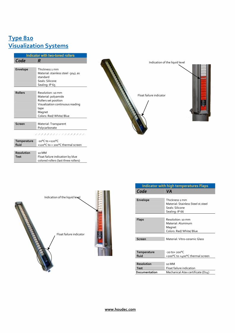
Type 810 Visualization Systems
Indication of the liquid level
Float failure indicator
Indication of the liquid level
Float failure indicator
Indicator with two-toned rollers
Code R
Envelope Thickness 1 mm Material: stainless steel -304L as
standard Seals: Silicone Sealing: IP 65
Rollers Resolution: 10 mm Material: polyamide Rollers set position Visualization continuous reading
tape Magnet Colors: Red/ White/ Blue
Screen Material: Transparent
Polycarbonate
Temperature fluid
-10°C to +120°C +120°C to + 200°C thermal screen
Resolution 10 MM Test Float failure indication by blue
colored rollers (last three rollers)
Indicator with high temperatures Flaps
Code VA
Envelope Thickness 1 mm Material: Stainless Steel st.steel Seals: Silicone Sealing: IP 66
Flaps Resolution: 10 mm Material: Aluminum Magnet Colors: Red/ White/ Blue
Screen Material: Vitro-ceramic Glass
Temperature fluid
-20 to+ 200°C +200°C to +400°C thermal screen
Resolution 10 MM
Test Float failure indication
Documentation Mechanical Atex certificate (D14)
Magnetic level gauge Technical manual
50466-604
- 18 -
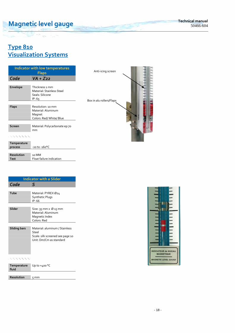
Type 810 Visualization Systems
Anti-icing screen
Box in alu rollers/Flaps
Indicator with low temperatures Flaps
Code VA + Z22
Envelope Thickness 1 mm Material: Stainless Steel Seals: Silicone IP: 65
Flaps Resolution: 10 mm Material: Aluminum Magnet Colors: Red/ White/ Blue
Screen Material: Polycarbonate ep:70
mm
Temperature process
-20 to -160°C
Resolution 10 MM Test Float failure indication
Indicator with a Slider
Code S
Tube Material: PYREX Ø24 Synthetic Plugs IP: 66
Slider Size: 35 mm x Ø 15 mm Material: Aluminum Magnetic Index Colors: Red
Sliding bars Material: aluminum / Stainless
Steel Scale: silk screened see page 10 Unit: Dm/Cm as standard
Temperature fluid
Up to +400 °C
Resolution 5 mm
www.houdec.com
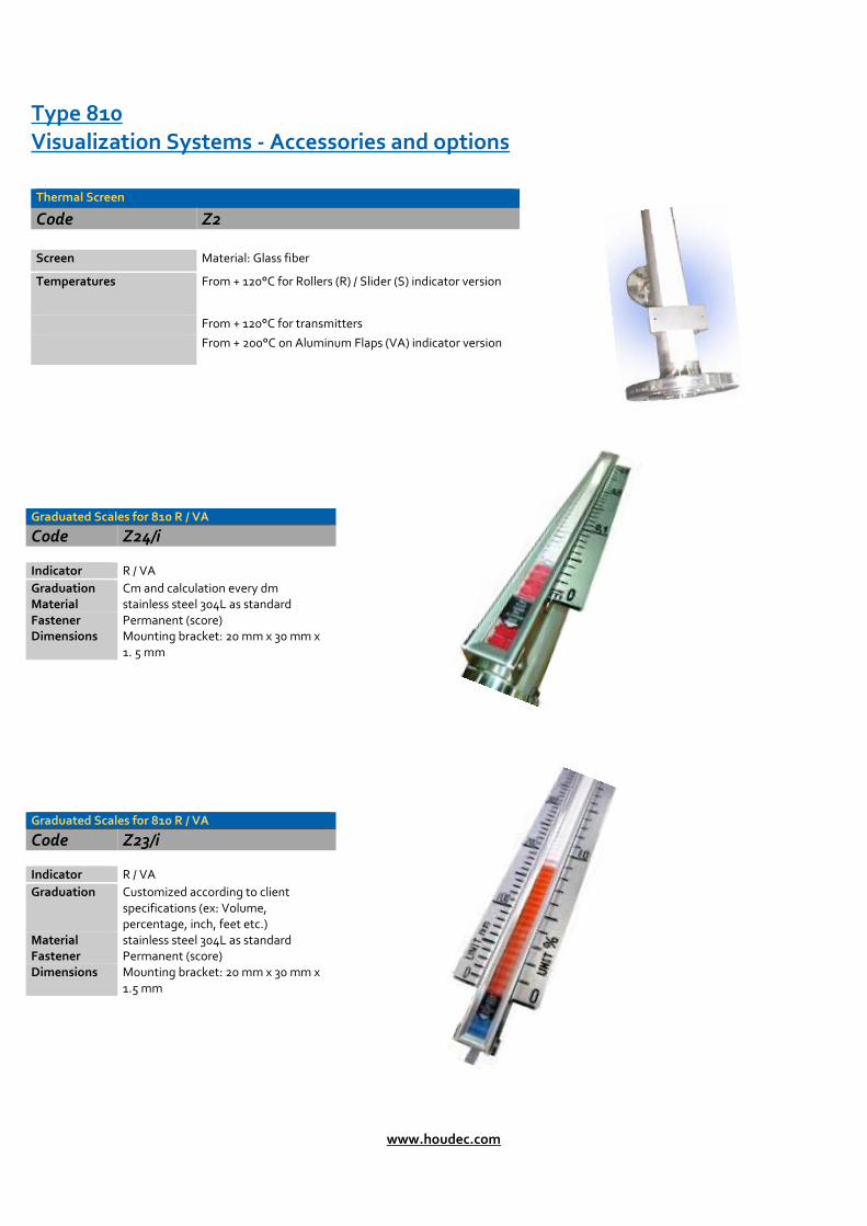
Type 810 Visualization Systems - Accessories and options
Thermal Screen
Code Z2
Screen Material: Glass fiber
Temperatures From + 120°C for Rollers (R) / Slider (S) indicator version
From + 120°C for transmitters
From + 200°C on Aluminum Flaps (VA) indicator version
Graduated Scales for 810 R / VA
Code Z24/i Indicator R / VA
Graduation Cm and calculation every dm Material stainless steel 304L as standard Fastener Permanent (score) Dimensions Mounting bracket: 20 mm x 30 mm x
1. 5 mm
Graduated Scales for 810 R / VA
Code Z23/i Indicator R / VA
Graduation Customized according to client specifications (ex: Volume, percentage, inch, feet etc.)
Material stainless steel 304L as standard Fastener Permanent (score) Dimensions Mounting bracket: 20 mm x 30 mm x
1.5 mm

Magnetic level gauge Technical manual
50466-604
- 20 -
Side connection for rolled welded chamber Ø60.3 x 2 codes C3 to C19
C3 C13
C4 C14
C5 C15
C6 C16
C7 C17
C8 C18
C8/1 C18/1
C8/2 C18/2
C9 C19
C9/1 C19/1
C9/2 C19/2
Bottom flange type 11B (Welding neck)
Reduced Bottom flange type Ø 99
PN10/16/40 PN20 (150 Lbs)
PN50 (300 Lbs)
PN10/16 PN20 (150 Lbs)
3000 Lbs 3000 Lbs 3000 Lbs Sch 10 Sch 40 Sch 40
Flange type 11B (WN)
DN ≤ 25 (1 ″)
Flange type 11B (WN)
DN ≤ 25 (1 ″)
Half sleeve
½″-¾″SW 3000 Lbs
Half sleeve
½″-¾″NPT-F 3000 Lbs
Half sleeve
½″-¾″BSPP-F 3000 Lbs
½″-¾″BW Tube
½″-¾″ Tube BSPP-M 3000 Lbs
½″-¾″ Tube NPT-M 3000 Lbs
Flange type 05B on 1" tune DN >25
Flange type 05B on 1" tune DN >25
CX : Other specific lateral links on request

www.houdec.com - 21 -
CX : Other specific lateral links on request
Side connection for seamless chamber Ø60.3 x 2.77 (Sch10) codes C20 to C32
C20
C21 C22 C30 C31 C32 C30/1 C30/2 C30/3 C31/1 C31/2 C31/3
Chamber flange type 11B (Welding neck -PN according to building code)
PN20 (150 Lbs)
PN50 (300 Lbs)
PN100 (600 Lbs)
PN20 (150 Lbs)
PN50 (300 Lbs)
PN100 (600 Lbs)
PN20 (150 Lbs)
PN20 (150 Lbs)
Sch 10 PN50 (300 Lbs)
PN50 (300 Lbs)
Sch 40
Flange type 11B (WN) DN ≤ 25 (1 ″)
Flange type 11B (WN) DN ≤ 25 (1 ″)
Half sleeve ½″-¾″
SW 3000 Lbs
Half sleeve ½″¾″
NPT- 3000 Lbs
½″-¾″-1″ Tube NPT-M 3000 Lbs
Half sleeve ½″-¾″-1″
SW 3000 Lbs
Half sleeve ½″-¾″-1″
NPT-F 3000 Lbs
Tube ½″-¾″-1″
NPT-M 3000 Lbs
Flange type 11B (WN) on discount
DN >25
Flange type 11B (WN) on discount
DN >25
Magnetic level gauge Technical manual
50466-604
- 22 -
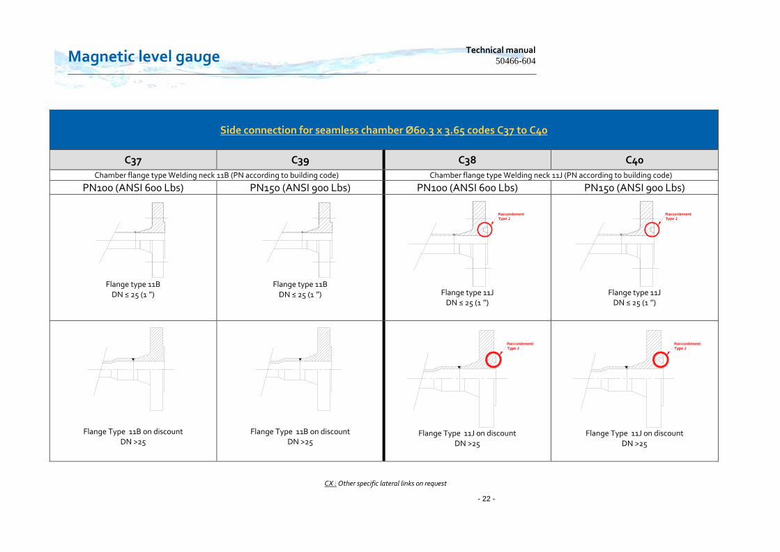
Side connection for seamless chamber Ø60.3 x 3.65 codes C37 to C40
C37 C39 C38 C40
Chamber flange type Welding neck 11B (PN according to building code) Chamber flange type Welding neck 11J (PN according to building code) PN100 (ANSI 600 Lbs) PN150 (ANSI 900 Lbs) PN100 (ANSI 600 Lbs) PN150 (ANSI 900 Lbs)
Flange type 11B
DN ≤ 25 (1 ″)
Flange type 11B
DN ≤ 25 (1 ″)
Raccordement
Type J
Flange type 11J
DN ≤ 25 (1 ″)
Raccordement
Type J
Flange type 11J
DN ≤ 25 (1 ″)
Flange Type 11B on discount DN >25
Flange Type 11B on discount DN >25
Raccordement
Type J
Flange Type 11J on discount
DN >25
Raccordement
Type J
Flange Type 11J on discount
DN >25
CX : Other specific lateral links on request
www.houdec.com - 23 -
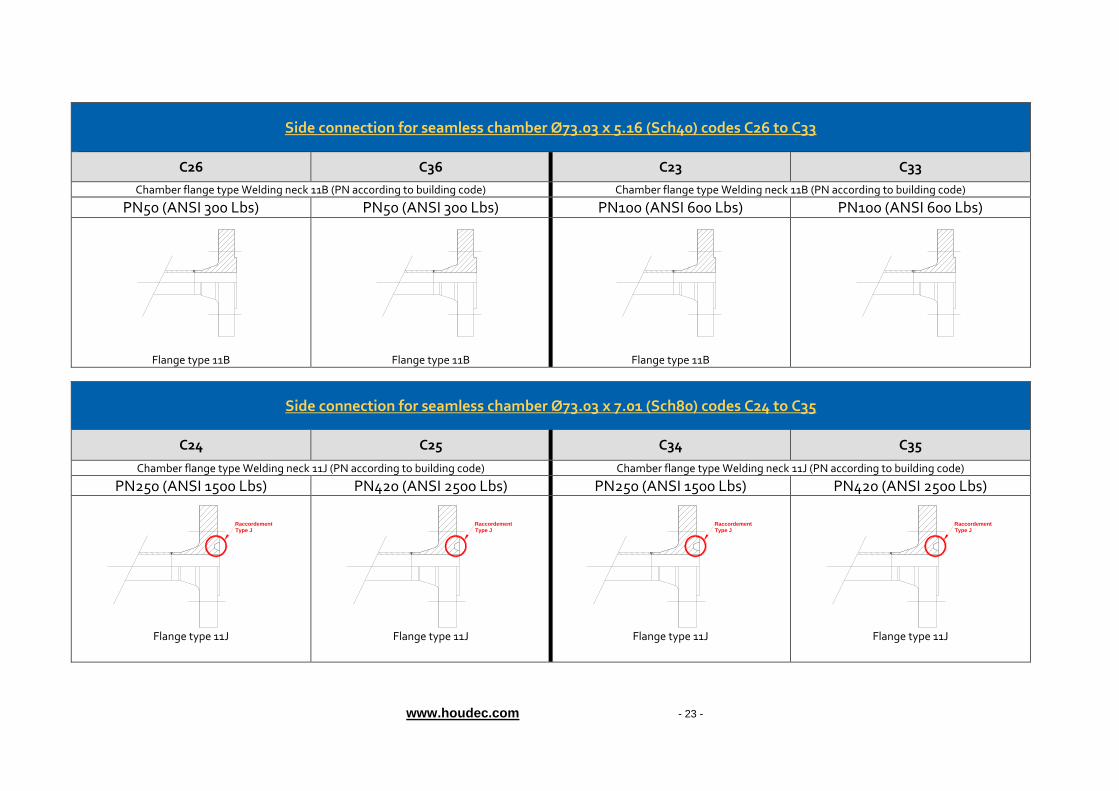
Side connection for seamless chamber Ø73.03 x 5.16 (Sch40) codes C26 to C33
C26 C36 C23 C33
Chamber flange type Welding neck 11B (PN according to building code) Chamber flange type Welding neck 11B (PN according to building code) PN50 (ANSI 300 Lbs) PN50 (ANSI 300 Lbs) PN100 (ANSI 600 Lbs) PN100 (ANSI 600 Lbs)
Flange type 11B
Flange type 11B
Flange type 11B
Side connection for seamless chamber Ø73.03 x 7.01 (Sch80) codes C24 to C35
C24 C25 C34 C35
Chamber flange type Welding neck 11J (PN according to building code) Chamber flange type Welding neck 11J (PN according to building code) PN250 (ANSI 1500 Lbs) PN420 (ANSI 2500 Lbs) PN250 (ANSI 1500 Lbs) PN420 (ANSI 2500 Lbs)
Raccordement
Type J
Flange type 11J
Raccordement
Type J
Flange type 11J
Raccordement
Type J
Flange type 11J
Raccordement
Type J
Flange type 11J
Magnetic level gauge Technical manual
50466-604
- 24 -
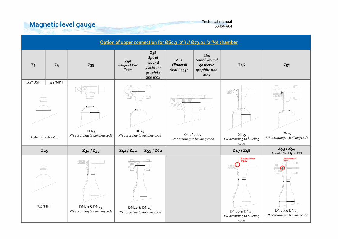
Option of upper connection for Ø60.3 (2’’) // Ø73.01 (2’’½) chamber
Z3 Z4 Z33 Z40
Klingersil Seal C4430
Z58 Spiral wound
gasket in graphite and inox
Z63 Klingersil
Seal C4430
Z64 Spiral wound
gasket in graphite and
inox
Z46 Z52
1/2″ BSP 1/2″NPT
DN15
PN according to building code
DN15
PN according to building code
On 2″ body
PN according to building code
DN15
PN according to building code
DN15
PN according to building code
Added on code ≥ C20
Z25 Z34 / Z35 Z41 / Z42 Z59 / Z60 Z47 / Z48 Z53 / Z54 Annular Seal type RTJ
3/4″NPT
DN20 & DN25 PN according to building code
DN20 & DN25 PN according to building code
Raccordement
Type J
DN20 & DN25
PN according to building code
Raccordement
Type J
DN20 & DN25 PN according to building code
www.houdec.com - 25 -
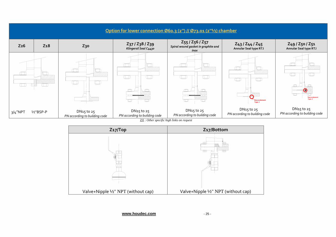
ZX : Other specific high links on request
Z17/Top Z17/Bottom
Valve+Nipple ½" NPT (without cap)
Valve+Nipple ½" NPT (without cap)
Option for lower connection Ø60.3 (2’’) // Ø73.01 (2’’½) chamber
Z26 Z18 Z30 Z37 / Z38 / Z39 Klingersil Seal C4430
Z55 / Z56 / Z57 Spiral wound gasket in graphite and
inox
Z43 / Z44 / Z45 Annular Seal type RTJ
Z49 / Z50 / Z51 Annular Seal type RTJ
3/4″NPT ½’’BSP-P
DN15 to 25 PN according to building code
DN15 to 25 PN according to building code
DN15 to 25 PN according to building code
Raccordement
Type J
DN15 to 25 PN according to building code
Raccordement
Type J
DN15 to 25 PN according to building code
Magnetic level gauge Technical manual
50466-604
- 26 -
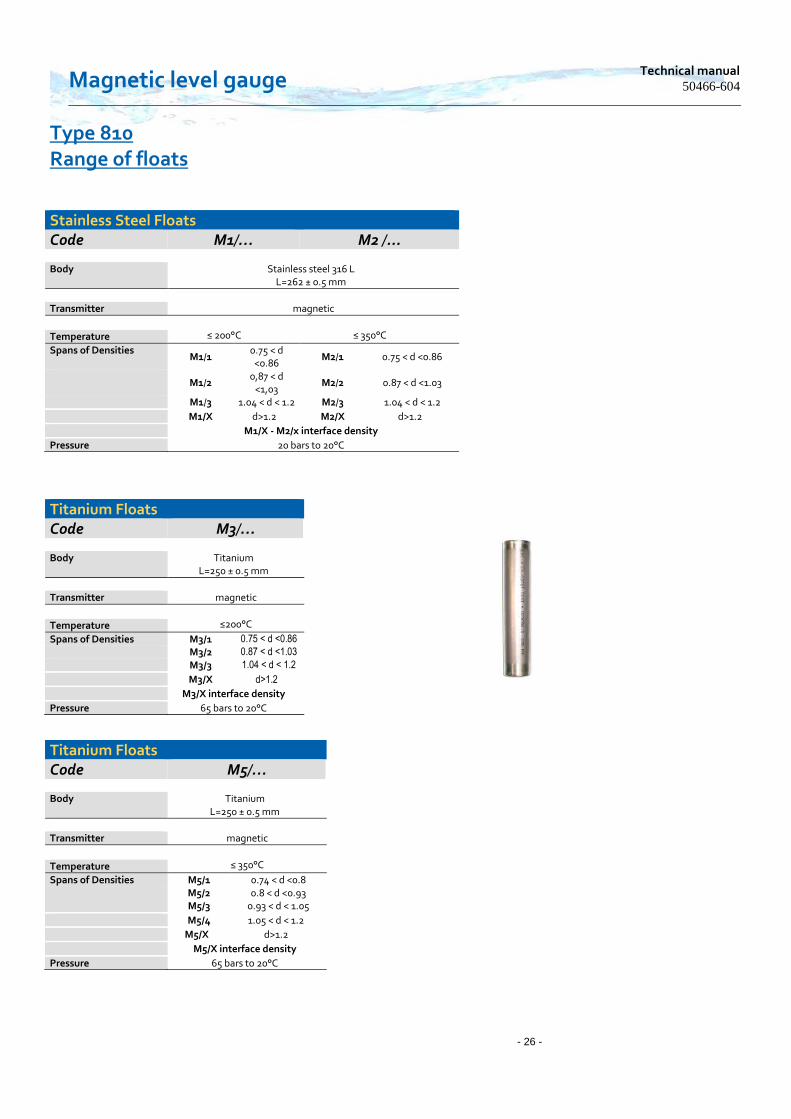
Type 810 Range of floats
Stainless Steel Floats Code M1/… M2 /...
Body Stainless steel 316 L L=262 ± 0.5 mm
Transmitter magnetic
≤ 200°C
≤ 350°C Temperature
Spans of Densities M1/1
0.75 < d <0.86
M2/1 0.75 < d <0.86
M1/2
0,87 < d <1,03
M2/2 0.87 < d <1.03
M1/3 1.04 < d < 1.2 M2/3 1.04 < d < 1.2
M1/X d>1.2 M2/X d>1.2
M1/X - M2/x interface density
Pressure 20 bars to 20°C
Titanium Floats Code M3/…
Body Titanium L=250 ± 0.5 mm
Transmitter magnetic
≤200°C Temperature
Spans of Densities M3/1 0.75 < d <0.86
M3/2 0.87 < d <1.03
M3/3 1.04 < d < 1.2
M3/X d>1.2
M3/X interface density
Pressure 65 bars to 20°C
Titanium Floats Code M5/…
Body Titanium L=250 ± 0.5 mm
Transmitter magnetic
≤ 350°C Temperature
Spans of Densities M5/1 0.74 < d <0.8 M5/2 0.8 < d <0.93 M5/3 0.93 < d < 1.05
M5/4 1.05 < d < 1.2
M5/X d>1.2
M5/X interface density
Pressure 65 bars to 20°C
www.houdec.com - 27 -
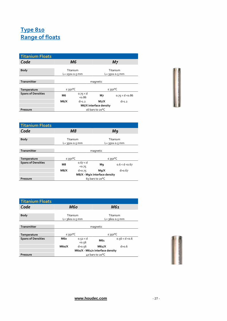
Type 810 Range of floats
Titanium Floats Code M6 M7
Body Titanium Titanium L= 250± 0.5 mm L= 350± 0.5 mm
Transmitter magnetic
≤ 350°C
≤ 350°C Temperature
Spans of Densities M6
0.75 < d <0.86
M7 0.75 < d <0.86
M6/X d>1.2 M7/X d>1.2
M6/X interface density
Pressure 16 bars to 20°C
Titanium Floats Code M8 M9
Body Titanium Titanium L= 350± 0.5 mm L= 350± 0.5 mm
Transmitter magnetic
≤ 350°C
≤ 350°C Temperature
Spans of Densities M8
0.67 < d <0.75
M9 0.6 < d <0.67
M8/X d>0.75 M9/X d>0.67
M8/X - M9/x interface density
Pressure 65 bars to 20°C
Titanium Floats Code M60 M61
Body Titanium Titanium L= 360± 0.5 mm L= 360± 0.5 mm
Transmitter magnetic
≤ 350°C
≤ 350°C Temperature
Spans of Densities M60 0.52 < d <0.56
M61 0.56 < d <0.6
M60/X d>0.56 M61/X d>0.6
M60/X - M61/x interface density
Pressure 40 bars to 20°C

Magnetic level gauge Technical manual
50466-604
- 28 -
Type 810 Range of floats
Titanium Floats Code M10 M11
Body Titanium Titanium L= 452± 0.5 mm L= 378± 0.5 mm
Transmitter magnetic
≤ 350°C
≤ 350°C Temperature
Spans of Densities M10 0.535 < d <0.57 M11 0.57 < d <0.635
M10/X d>0.57 M11/X d>0.635
M10/X- M11/X interface density
Pressure 140 bars to 20°C
Titanium Floats
Code M12/-- M13/--
Body Titanium Titanium L= 378± 0.5 mm L= 304± 0.5 mm
Transmitter magnetic
≤ 350°C
≤ 350°C Temperature
Spans of Densities M12/1 0.6 < d <0.649 M13/1 0.671 < d <0726
M12/2 0.587 < d <0.6 M13/2 0.65 < d <0.671
M12/X d>0.649 M13/X d>0726
M12/X - M13/x interface density
Pressure 140 bars to 20°C
Titanium Floats Code M14/-- M15/--
Body Titanium Titanium L= 230± 0.5 mm L= 156± 0.5 mm
Transmitter magnetic
≤ 350°C
≤ 350°C Temperature
Spans of Densities M14/1 0.785 < d <0.903 M15/1 1.05 < d <1.18
M14/2 0.726 < d <0.785 M15/2 0.904 < d <1.05
M14/X d>0.903 M15/X d>1.18
M14/X - M15/X interface density
Pressure 140 bars to 20°C

www.houdec.com - 29 -
Type 810 Range of floats
Titanium Floats Code M20/-- M21/--
Body Titanium Titanium L= 378± 0.5 mm L= 304± 0.5 mm
Transmitter magnetic
≤ 350°C
≤ 350°C Temperature
Spans of Densities M20/1 0.737 < d <0.78 M21/1 0.808 < d <0.876
M20/2 0.711 < d <0.736 M21/2 0.772 < d <0.807
M20/X d>0.78 M21/X d>0.876
M20/X - M21/X interface density
Pressure 240 bars to 20°C
Titanium Floats Code M40 M41
Body Titanium Titanium L= 230± 0.5 mm L= 230± 0.5 mm
Transmitter magnetic
≤ 350°C
≤ 350°C Temperature
Spans of Densities M40 0.52 < d <0.6 M41 0.43 < d<0.52
M40/X d>0.6 M41/X d>0.52
M40/X - M41/X interface density
Pressure 100 bars to 20°C
Titanium Floats Code M22/-- M23/--
Body Titanium Titanium L= 230± 0.5 mm L= 230± 0.5 mm
Transmitter magnetic
≤ 350°C
≤ 350°C Temperature
Spans of Densities M22/1 0.934 < d <1.043 M23/1 1.319 < d <1.38
M22/2 0.877 < d <0.933 M23/2 1.042 < d <1.32
M22/X d>1043 M23/X d>1.38
M22/X - M23/X interface density
Pressure 240 bars to 20°C
Titanium Floats Code M45
Body Titanium L=498 ± 0.5 mm
Transmitter magnetic
≤ 350°C Temperature
Spans of Densities M45 0.4 < d <0.43
M45/X d>0.43
M45/X interface density
Pressure 40 bars to 20°C
Magnetic level gauge Technical manual
50466-604
- 30 -
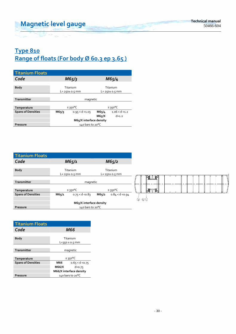
Type 810 Range of floats (For body Ø 60.3 ep 3.65 )
Titanium Floats Code M65/3 M65/4
Body Titanium Titanium L= 250± 0.5 mm L= 250± 0.5 mm
Transmitter magnetic
≤ 350°C
≤ 350°C Temperature
Spans of Densities M65/3 0.95 < d <1.05 M65/4 1.06 < d <1.2
M65/X d>1.2
M65/X interface density
Pressure 140 bars to 20°C
Titanium Floats Code M65/1 M65/2
Body Titanium Titanium L= 250± 0.5 mm L= 250± 0.5 mm
Transmitter magnetic
≤ 350°C
≤ 350°C Temperature
Spans of Densities M65/1 0.75 < d <0.83 M65/2 0.84 < d <0.94
M65/X interface density
Pressure 140 bars to 20°C
Titanium Floats Code M66
Body Titanium L=350 ± 0.5 mm
Transmitter magnetic
≤ 350°C Temperature
Spans of Densities M66 0.65 < d <0.75
M66/X d>0.75
M66/X interface density
Pressure 140 bars to 20°C

www.houdec.com - 31 -
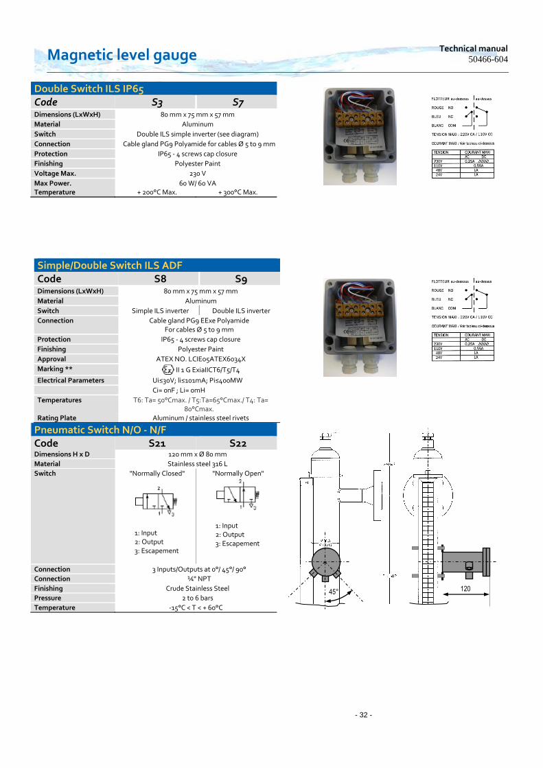
Type 810 Alarm Switch Each level gauge can be equipped with alarm Switch. These are adjusted in such a way that they can switch to the rise or descent from a chosen liquid level. NOTE: The options of alarm Switch for the gauges of type 810 can be installed for both versions indicator rolls (R), strands bicolor (VA) or follower (S). They are simply mounted against the main chamber through stainless steel clamps. The electrical connection is made by screw terminal and cable gland. NOTE: For each Switch, the cutting height and the orientation must be specified when ordering. Without any indication, the Switch will simply be mounted on the chamber and the client will have to bear the cost of setting. Option S20: "Tropicalisation" of Switch Switch can be added on the existing level gauges.
*** The ATEX marking complies with the Directive 94/09/CE, and certifies the Switch ILS and the enclosure.
Simple Switch ILS IP65 Code S1 S6 Dimensions (LxWxH) 80 mm x 75 mm x 57 mm
Material Aluminum
Switch ILS simple inverter
Connection Cable gland PG9 Polyamide For cables Ø 5 to 8 m
Protection IP65
Finishing Polyester Paint
Voltage Max. 230V
Max Power. 60 W/ 60 VA Temperature + 200°C Max. + 300°C Max.
Simple Switch / Double ILS ADF Code S2 S4 Dimensions (LxWxH) 80 mm x 75 mm x 57 mm
Material Aluminum
Switch simple ILS double ILS
Connection Cable gland ¾"NPT Aluminum for cables Ø 5 to 12 mm (supplied) Certified ADF ATEX ( "d")
Protection IP65/66 - Screw cover
Finishing Aluminum epoxy paint finish
Voltage Max. ILS 230V
Max Power. ILS 60 W/ 60 VA
Approval ATEX NO. LCIE01ATEX6060X
Marking *** II 2G ExdIICT6
Electrical Parameters Max Power.: 230 V (CE certificate) Max Current. : 15 A Max Power loss. : 20 W
Temperature Ta = -40°C at + 75°C Rating Plate Aluminum / stainless steel rivets
Magnetic level gauge Technical manual
50466-604
- 32 -
Double Switch ILS IP65 Code S3 S7 Dimensions (LxWxH) 80 mm x 75 mm x 57 mm
Material Aluminum
Switch Double ILS simple inverter (see diagram)
Connection Cable gland PG9 Polyamide for cables Ø 5 to 9 mm
Protection IP65 - 4 screws cap closure
Finishing Polyester Paint
Voltage Max. 230 V
Max Power. 60 W/ 60 VA Temperature + 200°C Max. + 300°C Max.
Simple/Double Switch ILS ADF Code S8 S9 Dimensions (LxWxH) 80 mm x 75 mm x 57 mm
Material Aluminum
Switch Simple ILS inverter Double ILS inverter
Connection Cable gland PG9 EExe Polyamide For cables Ø 5 to 9 mm
Protection IP65 - 4 screws cap closure
Finishing Polyester Paint
Approval ATEX NO. LCIE05ATEX6034X
Marking ** II 1 G ExiaIICT6/T5/T4
Electrical Parameters Ui≤30V; li≤101mA; Pi≤400MW
Ci= 0nF ; Li= 0mH
Temperatures T6: Ta= 50°Cmax. / T5:Ta=65°Cmax./ T4: Ta= 80°Cmax.
Rating Plate Aluminum / stainless steel rivets
Pneumatic Switch N/O - N/F Code S21 S22 Dimensions H x D 120 mm x Ø 80 mm
Material Stainless steel 316 L
Switch "Normally Closed"
1: Input 2: Output 3: Escapement
"Normally Open"
1: Input 2: Output 3: Escapement
Connection 3 Inputs/Outputs at 0°/ 45°/ 90°
Connection ¼" NPT
Finishing Crude Stainless Steel
Pressure 2 to 6 bars
Temperature -15°C < T < + 60°C
120 45°

www.houdec.com - 33 -
Type 810 Transmitters / continuous measurement 4-20mA
Each level gauge can be equipped with a magnetic transmitter for continuous measurement. An electronic line consisting of reed Switch thumbnails is inserted in a stainless steel tube maintained along the body of the appliance. This line acts as a control potentiometer guide by the movements of the float. The transmitter is housed in an IP65 aluminum enclosure, ATEX version or other on request. The transmitter can be added on an existing level gauge.
Construction Type Transmitter 4-20 mA
Tube Guide Stainless steel 316 L
Enclosures IP65 aluminum as standard ADF Aluminum "d"
Aluminum S.I. "ia" 316 L Stainless Steel "d" or "ia"
Construction Vertical is Standard
Angled optional **
Fastener Stainless Steel Clamps
Modules Standard Transmitters ATEX S. I. "ia" HART
HART ATEX S.I. "ia" HART LIN HART LIN ATEX S.I. "ia"
PR Type for CSA Approval
Max. Reading 5.5 m
Resolution 15 mm
Protection IP65 - IP67
Max Temperature + 300°C (insulation from 120°C)
0% - 4mA Cable gland Next option chosen
100% - 20mA
** The angled version is mandatory when the level gauge is equipped with a blowhole in the flange or when the transmitter is reversed 0% - 4mA

Magnetic level gauge Technical manual
50466-604
- 34 -
Type 810 Transmitters / continuous measurement 4-20 mA
* The transmitter module must be chosen from among the ATEX models certified by S. I.
Transmitter Code T1 - T1/C Protective Housing Type Square Standard Dimensions (LxWxH) 80 mm x 75 mm x 57 mm
Material Aluminum
Tube Guide Ø 14 mm Stainless Steel 316 L
Connection Cable gland PG9 Polyamide for cables Ø 6
to 11 mm
Protection IP65 - 4 screws cap closure Finishing Polyester Paint
Type XT42 -NIV (standard)
Output 4-20 mA 2 wires
Maximum Measurement
5.5 m
Power Supply 12 V < U < 30 V
Temperature -20°C < T < 70°C
Precision 0.15% full scale
Resolution 15 mm
Option Stainless steel housing code T20 - T20/C
Transmitter Code T2 – T2/C Protective Housing
Type Intrinsic Safety ("ia") * Dimensions (LxWxH) See diagram opposite
Tube Guide Ø 14 mm 316 L Stainless Steel on brass fitting ¾" NPT
Connection Cable gland PG9 EExe blue Polyamide
For cables Ø 5 to 8 mm
Protection IP65
Finishing Ash epoxy paint finish
Approval ATEX NO. LCIE05ATEX6034X
Marking ** II 1 G ExiaIICT6/T5/T4
Electrical Parameters Ui≤30V; li≤101mA; Pi≤758mW Or Ui≤28,4V; li≤116mA; Pi≤824mW Ci= 0nF ; Li= 0mH
Temperatures T6: Ta= 50°Cmax. / T5:Ta=65°Cmax. T4: Ta= 80°Cmax.
Rating Plate In accordance with existing regulations
Type XT42-NIV S.I
Output 4-20 mA - 2 wires
Maximum Measurement 5.5 m
Power Supply 12 V < U < 30 V
Temperature -20°C < T < 65°C
Precision 0.15% full scale
Resolution 15 mm
ATEX Approval Intrinsic Safety ("ia") *
Option CSA Approval (PR 5331)
Stainless steel housing code T21 - T21/C
www.houdec.com - 35 -
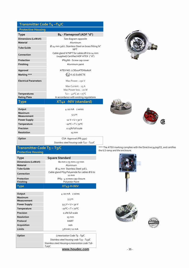
*** The ATEX marking complies with the Directive 94/09/CE, and certifies the ILS ramp and the enclosure.
Transmitter Code T4 –T4/C
Protective Housing
Type B4 - Flameproof (ADF "d")
Dimensions (LxWxH) See diagram opposite
Material Aluminum
Tube Guide Ø 14 mm 316 L Stainless Steel on brass fitting ¾"
NPT
Connection Cable gland ¾"NPT for cables Ø 6 to 14 mm
(supplied) Certified ADF ATEX ( "d")
Protection IP65/66 - Screw cap cover
Finishing Aluminum paint
Approval ATEX NO. LCIE01ATEX6060X
Marking *** II 2G ExdIICT6
Electrical Parameters Max Power.: 230 V
Max Current. : 15 A
Max Power loss. : 20 W
Temperatures Ta = - 40°C at + 75°C
Rating Plate In accordance with existing regulations
Type XT42 -NIV (standard)
Output 4-20 mA 2 wires
Maximum Measurement
5.5 m
Power Supply 12 V < U < 30 V
Temperature -20°C < T < 70°C
Precision 0.15% full scale
Resolution 15 mm
Option CSA Approval (PR 5331)
Stainless steel housing code T22 - T22/C
Transmitter Code T5 – T5/C Protective Housing
Type Square Standard Dimensions (LxWxH) 80 mm x 75 mm x 57 mm
Material Aluminum
Tube Guide Ø 14 mm Stainless Steel 316 L
Connection Cable gland PG9 Polyamide for cables Ø 6 to
11 mm
Protection IP65 - 4 screws cap closure Finishing Polyester Paint
Type XT43-H-NIV
Output 4-20 mA 2 wires
Maximum Measurement
5.5 m
Power Supply 9.5 V < U < 30 V
Temperature -20°C < T < 70°C
Precision 0.1% full scale
Resolution 15 mm
Protocol HART
Acquisition 10/s
Limits 3.8 mA / 22 mA
Option Linearization Code T9 - T9/C
Stainless steel housing code T23 - T23/C
Stainless steel Housing+Linearization code T26- T26/C

Magnetic level gauge Technical manual
50466-604
- 36 -
*** The ATEX marking complies with the Directive 94/09/CE, and certifies the transmitter, the ILS ramp and the enclosure.
Transmitter Code T6 – T6/C
Protective Housing
Type Intrinsic Safety ("ia") * Dimensions (LxWxH) See diagram opposite
Tube Guide Ø 14 mm 316 L Stainless Steel on brass fitting ¾" NPT
Connection Cable gland PG9 EExe blue Polyamide
For cables Ø 5 to 8 mm
Protection IP65
Finishing Ash epoxy paint finish
Approval ATEX NO. LCIE05ATEX6034X
Marking ** II 1 G ExiaIICT6/T5/T4
Electrical Parameters Ui≤30V; li≤101mA; Pi≤758mW
Or Ui≤28,4V; li≤116mA; Pi≤824mW
Ci= 0nF ; Li= 0mH
Temperatures T6: Ta= 50°Cmax. / T5:Ta=65°Cmax. T4: Ta= 80°Cmax.
Rating Plate In accordance with existing regulations
Type XT 43-HART S.I.
Output 4-20mA 2 wires
Maximum Measurement 5.5 m
Power Supply 9.5 V < U < 30 V
Temperature -20°C < T < 65°C
Precision 0.1% full scale
Resolution 15 mm
Protocol HART
Acquisition 10/s
Limits 3.8 mA / 22 mA
ATEX Approval Intrinsic Safety ("ia") *
Option CSA Approval (PR 5331)
Linearization Code T10- T10/C
Stainless steel housing code T24 - T24/C
Stainless steel Housing+Linearization code T27- T27/C

www.houdec.com - 37 -
Transmitter Code T7 –T7/C
Protective Housing
Type B4 - Flameproof (ADF "d")
Dimensions (LxWxH) See diagram opposite
Material Aluminum
Tube Guide Ø 14mm 316 L Stainless Steel on brass fitting ¾"
NPT
Connection Cable gland ¾"NPT for cables Ø 6 to 14mm
(supplied) Certified ADF ATEX ( "d")
Protection IP65/66 - Screw cap cover
Finishing Aluminum paint
Approval ATEX NO. LCIE01ATEX6060X
Marking *** II 2G ExdIICT6
Electrical Parameters Max Power.: 230 V
Max Current. : 15 A
Max Power loss. : 20 W
Temperatures Ta = - 40°C at + 75°C
Rating Plate In accordance with existing regulations
Type XT43-H-NIV
Output 4-20mA 2 wires
Maximum Measurement
5.5 m
Power Supply 9.5 V < U < 30 V
Temperature -20°C < T < 70°C
Precision 0.1% full scale
Resolution 15 mm
Protocol HART
Acquisition 10/s
Limits 3.8 mA / 22 mA
Option CSA Approval (PR 5331)
Linearization Code T11 - T11/C
Stainless steel Housing+Linearization code T25-
T25/C
Stainless steel Housing+Linearization code T28- T28/C
ISA Housing - 316 L Stainless Steel Dimensions (Øxh) Ø 103 mm, H=117 mm
Tube Guide Ø 14mm Stainless Steel 316 L
Connection Cable gland M20x1.5 Polyamide for cables Ø 5 to 9 mm
Protection IP67- closing by screw cover
Finishing Crude Stainless Steel
ADF Certified version
Marking *** II 2G ExdIICT6
Approval ATEX NO. LCIE01ATEX6060X
Connection Cable gland M20x1.5 Certified ADF "d" Stainless Steel
Protection IP67- closing by screw cover Finishing Crude Stainless Steel
MSPLOG

Magnetic level gauge Technical manual
50466-604
- 38 -
Type 810 PVC Version // PVC-C// PVDF // PPH (On study) Designed specifically for aggressive processes not incurred by a construction in stainless steel PVC Version: Connections : Rotating Flanges armed PP, PN10, DN25 with PVC clamps Minimum density: d=0.9 Max Pressure at ambient temperature: 6 bars (PxV < 25 for gas group I following the D. E. S P. 97/23/EC)
Maximum allowable Temperature : < 60°C at atmospheric pressure PPH Version : Connections : Rotating Flanges armed PP, PN10, DN25 with PVC clamps Minimum density: d=0.9 Max Pressure at ambient temperature: 6 bars (PxV < 25 for gas group I following the D. E. S P. 97/23/EC)
Maximum allowable Temperature : < 80°C at atmospheric pressure PVDF Version: Connections : Rotating Flanges armed PP, PN10, DN25 with PVC clamps Minimum density: d=0.9 Max Pressure at ambient temperature: 6 bars (PxV < 25 for gas group I following the D. E. S P. 97/23/EC)
Maximum allowable Temperature : < 140°C at atmospheric pressure
Special design and sheathing in special materials on request (Eg : 904L, Halar Coating, Hastelloy, etc. )

www.houdec.com - 39 -
Type 810 Documentation
Document Code Description
Instruction Manual
D0 Material certificate 3.1 (except Float)
D1 NACE MR-01-075 Certificate
D2 Welding book (CODAP - ASME)
D3 Calculation note (CODAP-ASME)
D4A
Information Folder - Design report CODAP or ASME - Material certificate 3.1 - Hydraulic test certificate
D4B
Information Folder - Material certificate 3.1 - Hydraulic test certificate
D6 Dye Penetrant test HOUDEC (Not certified COFREND-ASNT)
D7 Dye Penetrant 10% (Certified COFREND-ASNT)
D7A Dye Penetrant 20% (Certified COFREND-ASNT)
D8 Radiographic test 10% (Certified COFREND-ASNT)
D8A Radiographic test 20% (Certified COFREND-ASNT)
D9 Radiographic test 100% (Certified COFREND-ASNT)
D10 Point Zero (Certified COFREND-ASNT)
D11 Electronic documentation (CD-Rom - USB key)
D12 Technical drawing
D13 Hydraulic test certificate Material certificate 2.2
D14 ATEX mechanical certificate (Version 810VA only)

Magnetic level gauge Technical manual
50466-604
- 40 -
Sales Contact: Thomas Olivry Sales Manager
@ : [email protected] Tel : 04 70 59-56-74
Technical Contact: Stéphane Gaillard
Technical Manager @ : [email protected]
Tel : 04 70 59 56 73
After Sales Service: Cedric Aubert
Service Technician @ : [email protected]
Tel : 04 43 47 44 63