mmnmmmmmnminmmmmmmmmm - apps.dtic.mil · the trainer has optics which replicates the actual weapon...
TRANSCRIPT
fAD-Ai3S 375 IYTS-CEV (INTERACTIVE VIDEO TAPE SYSTEM-COMBAT ENGINEER 1/1VEHICLE) GUNNERY.. (U) ARMY PROJECT MANAGER FOR TRAININGDEVICES ORLANDO FL TECHNOLO.. FN NUNES 81 JUL 9t
UNCLASSIFIED PNT-ET-SOO5-A-81 N61339-80-C-184 F/G 5/9 ULmmnmmmmmnminmmmmmmmmm
mhmnnnnnnnnn.EEEEEEE nlmm

I 1.0 1112Ii.2~
11111.25 111 4
MICROCOPY RESOLUTION TEST CHARTNATIONAL BUREAU OF STANDARDS-1963-A
FINAL REPORT
IVTS-CEV
6 GUNNERY TRAINER
CONTRACT: N61339-8O-C-0104
CDRL SEQ. NUMBER A002 D 1
EL ~JULI
83 07 08 0Zv
fm plbb :i a ta

SL(.UNI IY (..LAbSIHL (A I I(N UP- I I PA tL (el,.n List. tnfteed)REPORT DOCUMENTATION PAGE READ INSTRUCTIONS
REPOT DCUMNTATON AGEBEFORE COMPLETING FORM1. REPORT NUMBER 2. GOVT ACCESSION NO. 3. RECIPIENT'S CATALOG NUMBER
PMT- ET- 0015-A-81[,, ..
4. TITLE (and Subtitle) 5. TYPE OF REPORT & PERIOD COVERED
Final Report: IVTS-CEV FinalGunnery Trainer
6. PERFORMING ORG. REPORT NUMBER
7. AUTHOR(a) S. CONTRACT OR GRANT NUMBER(@)
Alfred N. Nunes N61339-80-C-0104
9. PERFORMING ORGANIZATION NAME AND ADDRESS 10. PROGRAM ELEMENT. PROJECT. TASKAREA & WORK UNIT NUMBERS
Sanders Associates, In., Defensive Systems DivFederal Systems Group 62727A 1X762727A230Nashua, NH 03061
II. CONTROLLING OFFICE NAME AND ADDRESS 12. REPORT DATEProject Manager Training Devices, Operations, 1 July 1981Research, & Engineering Management Div, Technology 13. NUMBER OF PAGES
Management Br (DRCPM-TND-ET), NTC, Orlando FL 32813 5814. MONITORING AGENCY NAME & ADDRESS(If different from Controlling Office) IS. SECURITY CLASS. (of this report)
UnclassifiedISa. DECL ASSI FICATION/DOWN GRADI NG
SCHEDULE l.
16. DISTRIBUTION STATEMENT (of this Report)
Approved for public release and distribution unlimited.
17. DISTRIBUTION STATEMENT (of the abstract entered In Block 20, If different from Report)
IS. SUPPLEMENTARY NOTES
KEY WORDS (Continue on reverse side if necoeamy and identify by block number)
(U) Total Force (U) Gunnery(U) Training Devices (U) Tank(U) Tactical (U) Interactive(U) Concept Development (U) Video(U) Simulation (U) Target Acquisition
20. A9MTRACT (c..v.1d N a d identify by block number)- The IVTS project demonstrates the feasibility of applying to military training .
applications the video game technology developed for and marketed in consumervideo games. The IVTS/CEV is a conceptual/breadboard-level classroom inter-active training system designed to train Combat Engineer Vehicle (CEV) gunnersin target acquisition and engagement with the main gun. t The concept demon-stration consists of two units: a gunner station and a display module. Thegunner station has optics and gun controls replicating those of the CEV gunner - _station. The display module contains a standard large-screen color video -
S 73 1473 EDITION OF I NOVS IS OSLETE UnclassifiedSECURITY CLASSIFICATION OF THIS PAGE (When Date Entered)
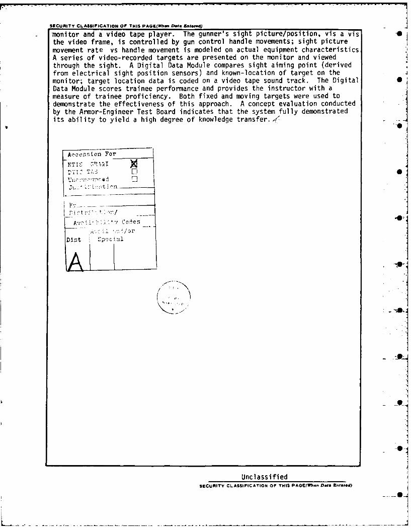
SECUNITY CLASSIFICATION OF THIS PAGE(Wmmn Deea AnOw ed) 2monitor and a video tape player. The gunner's sight picture/position, vis a vis -the video frame, is controlled by gun control handle movements; sight picturemovement rate vs handle movement is modeled on actual equipment characteristicsA series of video-recorded targets are presented on the monitor and viewedthrough the sight. A Digital Data Module compares sight aiming point (derivedfrom electrical sight position sensors) and known-location of target on themonitor; target location data is coded on a video tape sound track. The DigitalData Module scores trainee performance and provides the instructor with ameasure of trainee proficiency. Both fixed and moving targets were used todemonstrate the effectiveness of this approach. A concept evaluation conductedby the Armor-Engineer Test Board indicates that the system fully demonstratedits ability to yield a high degree of knowledge transfer.,(
Accession For
YTIS cA'A I
F',
-t i tr- 1 /
Di Cales
Dist p id
UnclassifiedSECuAITY CLASSIFICATION OF THIS PAGE(When Data Rnetred)
TABLE OF CONTENTS
0
1.0 Introduction -
1.1 General
1.2 Development
1.3 Concept Evaluation
2.0 Program Report 0
2.1 Introduction
2.2 Applications Hardware
2.3 Telescope
2.4 Power Control Unit
2.5 Gunners Switch Box
2.5.1 Elev/Trav Power
2.5.2 Main Gun
2.6 Helmet and Headset
2.7 Training Function --
2.7.1 Direct Fire Adjustment
2.7.2 "BOT" Correction
2.8 Typical Scenario -
2.8.1 Scenario Sequence
2.9 Target Engagement
2.10 Scenario Types S
2.10.1 Time Assumptions
2.10.2 Single Impact Point
2.10.3 Multi-Impact Point
2.11 Scoring
2.12 Video Tape
2.12.1 Audio
2.12.2 Video ! -j"'6
2.13 DDM Digital Data
2.13.1 Start of New Scenario
2.13.2 Number of Impact Scenario
2.13.3 TC/Gunner BOT
2.13.4 Windage and Cant Factors
2.13.5 Range Data
2.13.6 Number of Rounds Required
2.13.7 Impact Number and Position
2.14 Video Display
2.14.1 Background Scenario
2.14.2 Impact Explosion/Miss
2.14.3 Cease Fire
2.14.4 Tank Commander Command
2.14.5 Score
2.15 System Software Flow
2.15.1 System Initialization Time
2.15.1.1 Hit Resolution Constant
2.15.1.2 Impact Symbol Display Time
2.15.1.3 Score Initialization
2.15.1.4 Initial Tape Position
2.15.2 Digital Input Data Flow

2.15.3 End of Session
2.16 TV Sweep Accuracy B
2.17 Video Tape Data Recording Error Rate
3.0 Videotape Cassette/Videodisk Comparison
3.1 Videotape Cassette Recorder/Players
3.2 Record/Playback
3.3 Videodisk
3.3.1 MCA/PHILLIPS Optical-Laser System B
3.3.2 Thomson-CSF Optical-Laser System
3.3.3 RCA Capacitance System
3.3.4 Matsushita/JVC VHD System
3.4 Comparison of Videotape to Videodisks
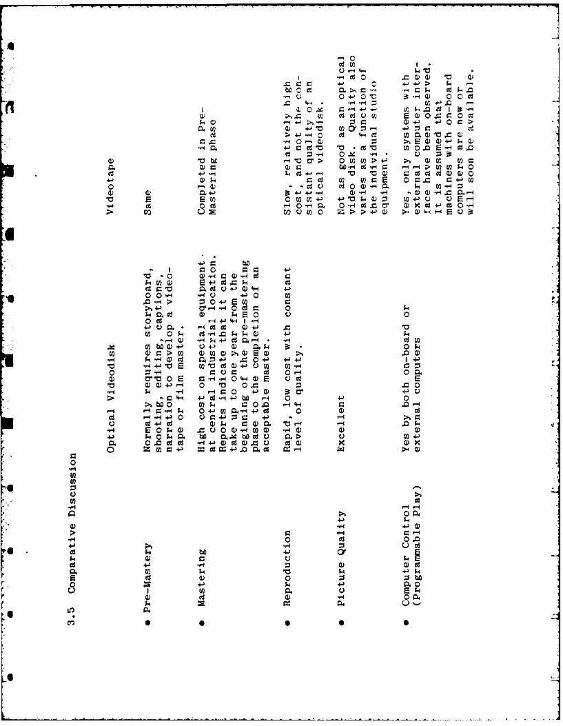
3.5 Comparative Discussion
3.6 Comments
4.1 Recommended Changes
5.0 Recommended Application of IVTS Technology
5.1 Machinegun Training
5.1.1 Marksmanship Training
5.1.2 IVTS Application
5.1.3 Physiological Requirements
5.1.4 Sound
5.1.5 Aim Point Measurement0
5.1.6 Cost Trade-Off
5.2 Mortar Gunnery Training Device (IVTS)
5.2.1 Mortar Gunnery Problem
5.2.2 Target Presentation
Ki.
5.2.3 Estimation of Distance
5.2.4 Measurement of Angles S
5.2.5 Call for Fire, Manual FDC
5.2.6 Call for Fire, Mortar Computer Ballistic's XM-23
5.2.7 Training System "0
1..'
.• ,- _

1.0 INTRODUCTION
1.1 General
This is the final report on IVTS/CEV concept development
and test required under the provisions of Contract N61339-80-C-1014,
CDRL sequence A002. The report covers development, concept evaluation,
recommended changes and recommended application of the IVTS concept
to other training requirements.
1.2 Development
The IVTS/CEV contract was awarded in July, 1980. Its pur-
pose was to develop a classroom trainer for the M-728 Combat Engineer
Vehicle main gun. The trainer has optics which replicates the actual
weapon system. Optical scan is controlled by a simulated power con-
trol system that looks and feels the same as the M-728 vehicle. A
series of targets are recorded on a video tape and are presented to
the trainee on a television screen. Interaction is provided through
Sander's Interactive Video Training System Digital Data Module (DDM).
This module decodes target location data which is stored on the video
tape and compares the target location to gunner aim point. The
module scores the trainee and provides the instructor with a measure
of trainee proficiency. Both fixed and moving targets were used to
demonstrate the effectiveness of this system.
1.3 Concept Evaluation
Concept Evaluation was conducted at Ft. Knox, KY by the
Armor Engineer Test Board. Results of the evaluation indicates that
the system fully demonstrated its ability to transfer knowledge to
trainees on M728 Combat Engineer Vehicle Gunnery tasks. A complete
report is being submitted by the Board.!
4
1. Kimble, Capt Jerry D., and Will D. Hahn, Concept Evaluation Program of InteractiveVideo Tape System (IVTS) Evaluation for Gunnery Training on the Combat EngineerVehicle, U.S. Army Armor and Engineer Test Board, Ft. Knox, KY, September 1981.TRADOC TRMS No. 1-CEPO04.
4
PROGRAM REPORT
2.1 Introduction
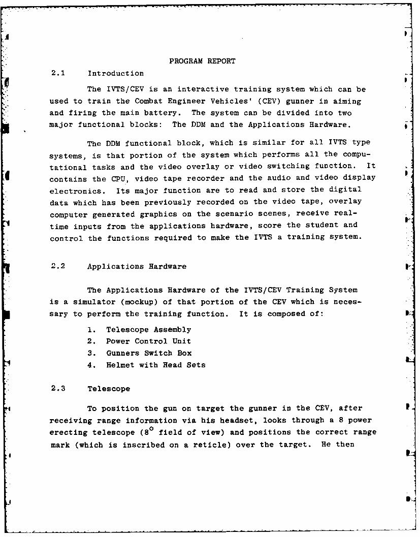
The IVTS/CEV is an interactive training system which can be
used to train the Combat Engineer Vehicles' (CEV) gunner in aiming
and firing the main battery. The system can be divided into two
major functional blocks: The DDM and the Applications Hardware.
The DDM functional block, which is similar for all IVTS type
systems, is that portion of the system which performs all the compu-
tational tasks and the video overlay or video switching function. It
contains the CPU, video tape recorder and the audio and video display
electronics. Its major function are to read and store the digital
data which has been previously recorded on the video tape, overlay
computer generated graphics on the scenario scenes, receive real-
time inputs from the applications hardware, score the student and
control the functions required to make the IVTS a training system.
2.2 Applications Hardware
The Applications Hardware of the IVTS/CEV Training System
is a simulator (mockup) of that portion of the CEV which is neces-
sary to perform the training function. It is composed of:
1. Telescope Assembly
2. Power Control Unit
3. Gunners Switch Box
4. Helmet with Head Sets
2.3 Telescope
To position the gun on target the gunner in the CEV, after
receiving range information via his headset, looks through a 8 power0erecting telescope (8 field of view) and positions the correct range
mark (which is inscribed on a reticle) over the target. He then
m
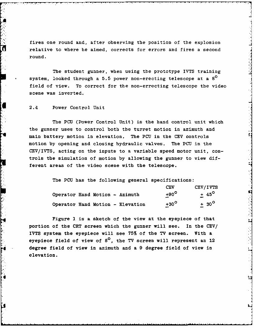
fires one round and, after observing the position of the explosion
relative to where he aimed, corrects for errors and fires a second
round.
The student gunner, when using the prototype IVTS training
system, looked through a 5.5 power non-erecting telescope at a 80
field of view. To correct for the non-errecting telescope the video
scene was inverted.
2.4 Power Control Unit
The PCU (Power Control Unit) is the hand control unit which
the gunner uses to control both the turret motion in azimuth and
main battery motion in elevation. The PCU in the CEV controls
motion by opening and closing hydraulic valves. The PCU in the
CEV/IVTS, acting on the inputs to a variable speed motor unit, con-
trols the simulation of motion by allowing the gunner to view dif-
ferent areas of the video scene with the telescope.
The PCU has the following general specifications:
CEV CEV/IVTS
Operator Hand Motion - Azimuth +900 + 450
Operator Hand Motion - Elevation +300 + 300
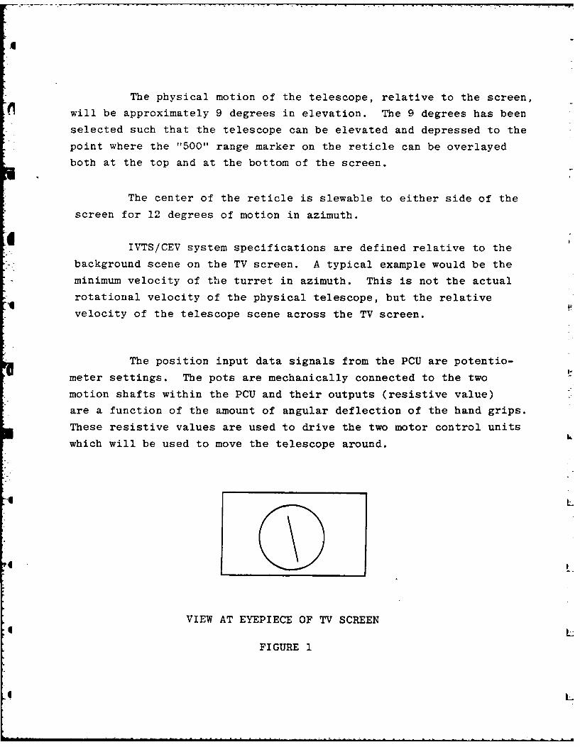
Figure I is a sketch of the view at the eyepiece of that
portion of the CRT screen which the gunner will see. In the CEV/
IVTS system the eyepiece will see 75% of the TV screen. With a
eyepiece field of view of 80, the TV screen will represent an 12
degree field of view in azimuth and a 9 degree field of view in
elevation.
:t L
AJ
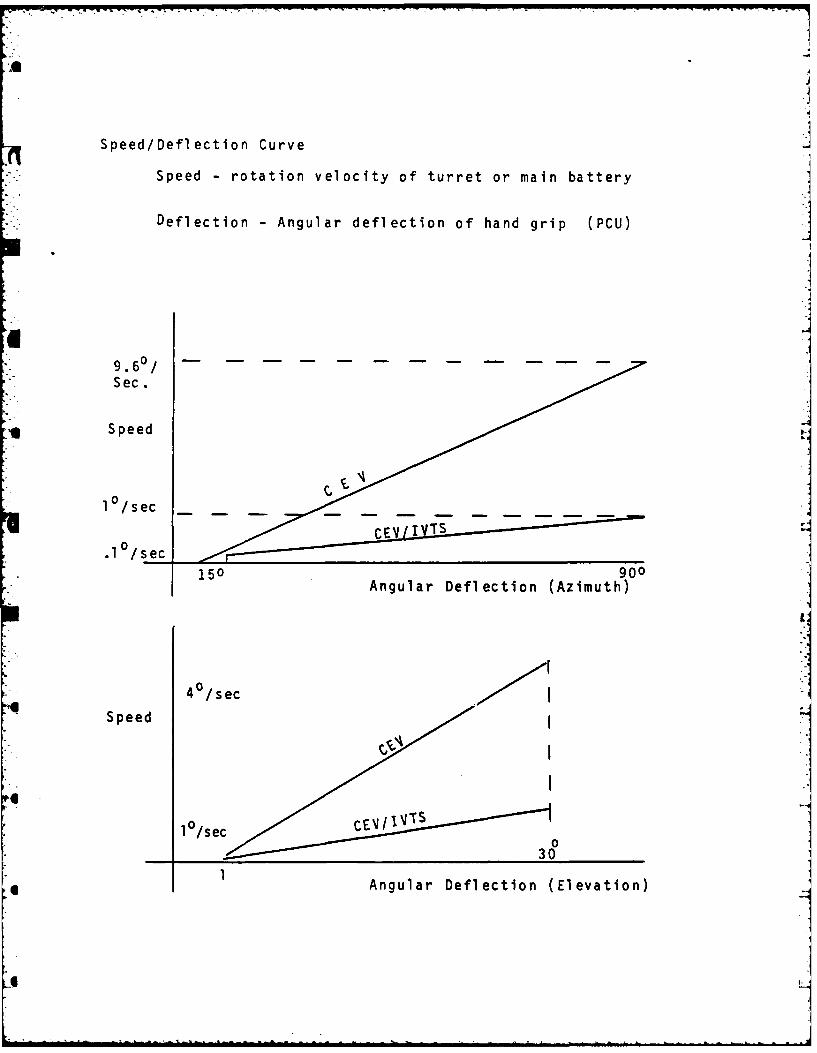
Speed/Deflection Curve
Speed - rotation velocity of turret or main battery
Deflection - Angular deflection of hand grip (PCU)
9.6 0 / . .. ....
Sec.
Speed
*1 0 /sec
1 /sec 150s 900150 Angular Deflection (Azimuth)
Is
40 /sec
A uq Speed (lvto
1 Angular Deflection(Eeain
6 n
The physical motion of the telescope, relative to the screen,
will be approximately 9 degrees in elevation. The 9 degrees has been
selected such that the telescope can be elevated and depressed to the
point where the "500" range marker on the reticle can be overlayed
both at the top and at the bottom of the screen.
The center of the reticle is slewable to either side of the
screen for 12 degrees of motion in azimuth.
IVTS/CEV system specifications are defined relative to the
background scene on the TV screen. A typical example would be the
minimum velocity of the turret in azimuth. This is not the actual
rotational velocity of the physical telescope, but the relative
velocity of the telescope scene across the TV screen.
The position input data signals from the PCU are potentio-
meter settings. The pots are mechanically connected to the two
motion shafts within the PCU and their outputs (resistive value)
are a function of the amount of angular deflection of the hand grips.
These resistive values are used to drive the two motor control units
which will be used to move the telescope around.
L
VIEW AT EYEPIECE OF TV SCREEN
FIGURE 1
L
2.5 Gunners Switch Box
The Gunners Switch Box on the CEV/IVTS system is physi-
cally similar to the CEV Gunner Switch Box. The box has three (3)
switches and three associated indicator lights. The function of
these switches are:
2.5.1 Elev/Trav Power
When this switch is turned on (up position), the gunner will
be able to move the telescope across the face of the TV screen.
2.5.2 Main Gun
This switch will supply power to the indicator light above
it. This is the only function that it will perform.
2.6 Helmet and Headset
It is assumed that each student gunner will use his own
helmet. The audio inputs to the headset will be Tank Commander
commands and instructions (audio portion of the video tape) and
background explosions (computer generated audio).
2.7 Training Function
The CEV/IVTS application software is designed to perform
the following training features:
2.7.1 Direct Fire Adjustment
The definition of Direct Fire Adjustment is as contained in
Section 5 of the Field Manual FM5-12F 1/2 and 5-12F 3/4 "Solders
Manual MOS12F CEV Crewman". The central theme in Direct-Fire Adjust-
ment is the burst on target (BOT) method.
To perform the BOT method, either the gunner or the Tank
Commander observes the round impact area to perform an aiming point
correction.
2.7.2 After the first round, the gunner observes the impact area.
If he sees an explosion he will perform a "BOT" correction. If he
does not see an explosion he will assume that the TC will perform the
"BOT" correction.
For a TC "BOT" the correction data will be displayed on
the TV screen in the following format.
UP 100 (METERS)
LEFT 2 (MILS)
2.8 Typical Scenario - Stationary target at 400 yards
2.8.1 Scenario Sequence
Gunner hears video taped audio "Gunner-Two Rounds HEP -
Bridge - 400 yards - Fire".
Simultaneously with audio (if gunner is looking into eye-
piece of telescope) he will see a background scene. The target will
appear within the 8 degree field of view on the TV screen. Using the
Position Control Unit the gunner slews the main battery in both range
and azimuth to position the correct range mark on the reticle over
the target. The gunner waits until he hears the "up" command from
the loader. The gunner fires one round and checks the position of
the burst, corrects the error, and fires the second round.
Depending upon the number of rounds the TC has requested
(Two Rounds HEP), the gunner may correct again for error and fire
another round. After the gunner fires the number of rounds specified
by the TC, the trigger switch is locked out until the start of the
next scenario. At this time, "Cease Fire", the number of rounds
4 fired and the number of hits will be displayed on the screen.
L
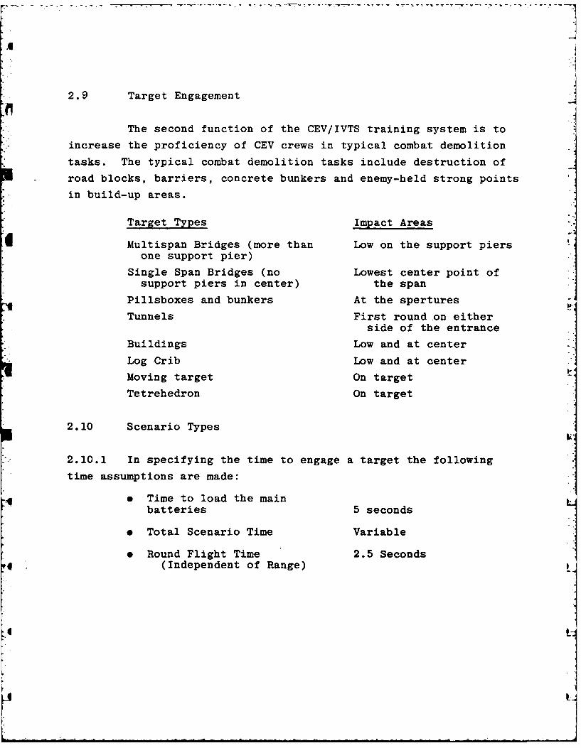
2.9 Target Engagement
The second function of the CEV/IVTS training system is to
increase the proficiency of CEV crews in typical combat demolition
tasks. The typical combat demolition tasks include destruction of
road blocks, barriers, concrete bunkers and enemy-held strong points
in build-up areas.
Target Types Impact Areas
Multispan Bridges (more than Low on the support piersone support pier)
Single Span Bridges (no Lowest center point ofsupport piers in center) the span
Pillsboxes and bunkers At the spertures
Tunnels First round on eitherside of the entrance
Buildings Low and at center
Log Crib Low and at center
Moving target On target
Tetrehedron On target
2.10 Scenario Types
2.10.1 In specifying the time to engage a target the following
time assumptions are made:
* Time to load the main
batteries 5 seconds
• Total Scenario Time Variable
* Round Flight Time 2.5 Seconds
4 (Independent of Range)
It

.A
2.10.2 Single Impact Point
When the gunner fires at this type of target, there is
only one specific point which will be classified as the attack point.
Targets classified as Single Impact Points are buildings, moving
targets, log cribs and tetrahedrons.
2.10.3 Multi-Impact Point
When the gunner fires at this type of target, there is
more than one point (max. of 15) which will be classified as the
attack point. Targets classified as Multi-Impact Points are single
span bridges, multi-span bridges, pill boxes, tunnels, etc.
2.11 Scoring
In order to evaluate a student's performance and to give a
competitive spirit, a student's performance score is displayed at
the end of the training session. The training session can be stopped
by depressing the required key on the keyboard.
The scoring method is to measurethe lapse time between
"Target Visible" and "Trigger Pull" and between "Impact Symbol"
and "Trigger Pull" and to compare this time against successful
hits.
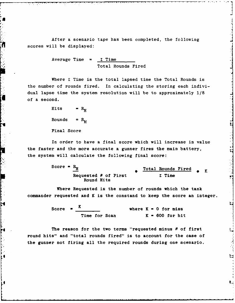
After a scenario tape has been completed, the following
scores will be displayed:
Average Time = E Time
Total Rounds Fired
Where E Time is the total lapsed time the Total Rounds is
the number of rounds fired. In calculating the storing each indivi-
dual lapse time the system resolution will be to approximately 1/8
of a second.
Hits = RH
Rounds = RM
Final Score
In order to have a final score which will increase in value
the faster and the more accurate a gunner fires the main battery,
the system will calculate the following final score:
Score RH Total Rounds Fired 0
Requested # of First E TimeRound Hits
Where Requested is the number of rounds which the tank
commander requested and K is the constand to keep the score an integer.
KScore - where K - 0 for miss
Time for Scan K - 600 for hit
The reason for the two terms "requested minus # of first
round hits" and "total rounds fired" is to account for the case of
the gunner not firing all the required rounds during one scenario.
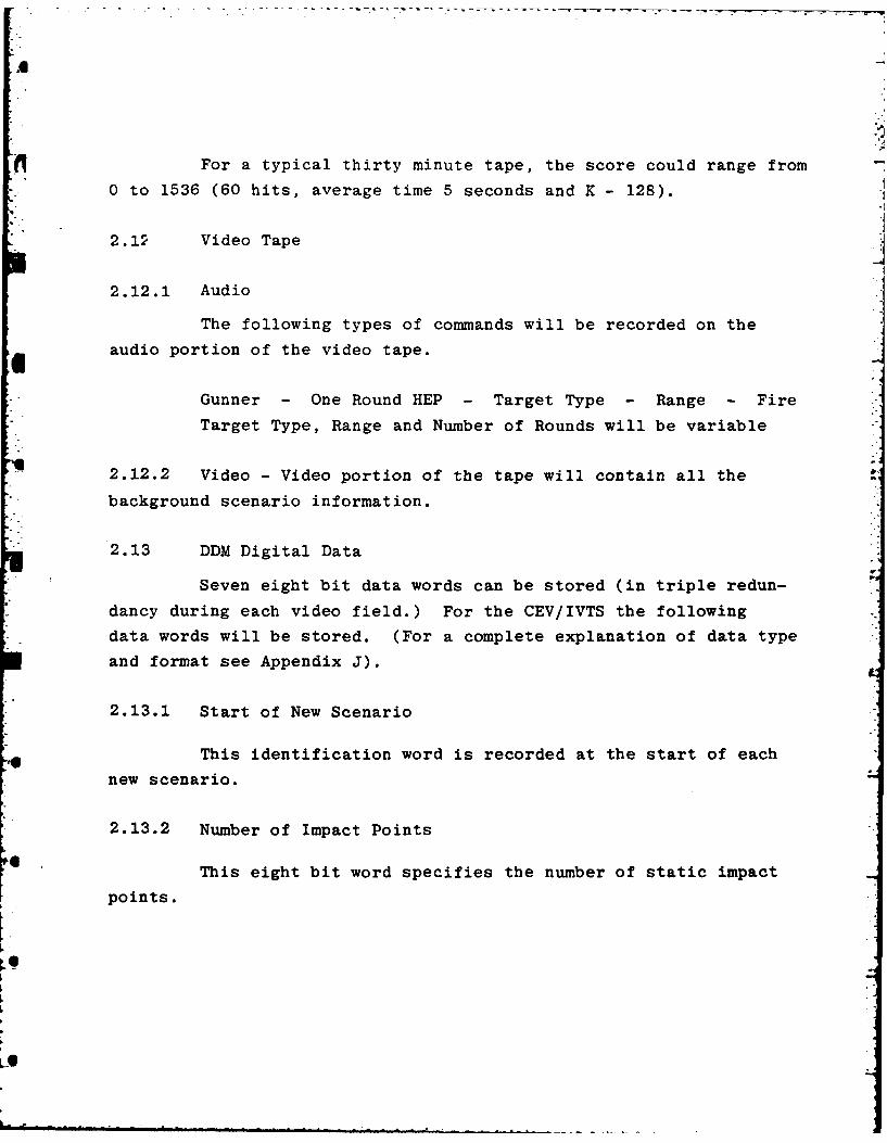
For a typical thirty minute tape, the score could range from
0 to 1536 (60 hits, average time 5 seconds and K - 128).
2.12 Video Tape
2.12.1 Audio
The following types of commands will be recorded on the
audio portion of the video tape.
Gunner - One Round HEP - Target Type - Range - Fire
Target Type, Range and Number of Rounds will be variable
2.12.2 Video - Video portion of the tape will contain all the
background scenario information.
2.13 DDM Digital Data
Seven eight bit data words can be stored (in triple redun-
dancy during each video field.) For the CEV/IVTS the following
data words will be stored. (For a complete explanation of data type
and format see Appendix J).
2.13.1 Start of New Scenario
This identification word is recorded at the start of each
new scenario.
2.13.2 Number of Impact Points
This eight bit word specifies the number of static impact
points.
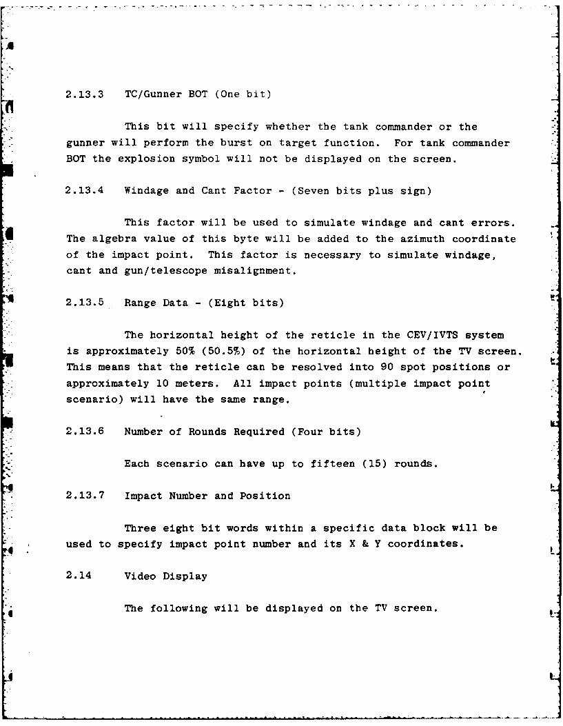
2.13.3 TC/Gunner BOT (One bit)
This bit will specify whether the tank commander or the
gunner will perform the burst on target function. For tank commander
BOT the explosion symbol will not be displayed on the screen.
2.13.4 Windage and Cant Factor - (Seven bits plus sign)
This factor will be used to simulate windage and cant errors.
The algebra value of this byte will be added to the azimuth coordinate
of the impact point. This factor is necessary to simulate windage,
cant and gun/telescope misalignment.
2.13.5 Range Data - (Eight bits)
The horizontal height of the reticle in the CEV/IVTS system
is approximately 50% (50.5%) of the horizontal height of the TV screen.
This means that the reticle can be resolved into 90 spot positions or
approximately 10 meters. All impact points (multiple impact point
scenario) will have the same range.
2.13.6 Number of Rounds Required (Four bits)
Each scenario can have up to fifteen (15) rounds.
2.13.7 Impact Number and Position
Three eight bit words within a specific data block will be
used to specify impact point number and its X & Y coordinates.
2.14 Video Display
The following will be displayed on the TV screen.
-A
2.14.1 Background Scenario
The background scenario will be prerecorded on video tape
and played back through the system on the TV screen.
2.14.2 Impact Explosion/Miss
When the gunner fires the main battery this symbol is dis-
played on the TV screen (gunner sees it through the telescope) at
the impact point. The impact point is the point where the gunner
is pointing his gun (this point will be modified by both the Cant/
Windage factor and the range correction factor). Depending upon type
of tape, this symbol will be displayed for one or two seconds after
impact.
2.14.3 Cease Fire
After the gunner has fired the required number of rounds
the following information will be displayed on the screen:
Cease Fire
Rounds 2
Hits 1
The number of rounds and the number of hits will be for the
just completed scenario only.
2.14.4 Tank Commander Command
If the scenario is a TC/BOT type, the adjustment commandwill be displayed on the TV screen after the Impact Explosion symbol
has been removed. The displayed format will be
4 UP 100 (METERS)
LEFT 2 (MILS)

2.14.5 Score
After the training session has been completed the final
score will be displayed. The displayed format will be
Average Time - Seconds
Rounds
Hits
Score
2.15 System Software Flow
2.15.1 System Initialization Time
At system initialization time the following constants
may be changed.
2.15.1.1 Hit Resolution Constant
The Hit Resolution Constant defines the area around theimpact point into which the rounds must land for the student to get a
hit.
2.15.1.2 Impact Symbol Display Time
4 Impact Symbol Display Time variable, will be set up atinitialization time. This variable will range from zero to appro-ximately four seconds in 16.7 millisecond increments (8 bits).
2.15.1.3 Score Initialization
At initialization time the gunners scores will be set to
zero.
2.15.1.4 Initial Tape Position
In operating the system as a training device it is not neces-
sary to start the video tape at the beginning. It is possible to
start the training session at any part of the tape.
2.15.2 Digital Input Data Flow
The start of a new scenario is when the gunner hears the
tank commander's voice on the audio portion of the tape. To the
microprocessor, the start of a new scenario is when the micropro-
cessor receives the "Start New Scenario" data block.
The sequence of data blocks is:
1) Start of New Scenario
2) Target position and number
3) Target position and number (if required)
4) Target position and number (if required)
5) Target position and number (if required)
Depending upon the software configuration within the tape
annotator, range and target position data may be sent only once or
continuously transmitted. Each time the microprocessor receives
range or position data, it updates these words. For a stationary
target, the range and position data should be constant throughout
the scenario. For a moving target it can vary.
Upon receiving the "Start of New Scenario" data block, a
software timer is started. After approximately five seconds (the
time it takes for the loader to load the first round), the software
outputs in "up" command (via the noise generator) and starts the
lapse time counter (at score calculation time the value of the lapse
time will be divided by the number of fired rounds to determine the
"Average Time").
.. . . . .
The gunner hears the "UP" command and, knowing that the
main battery is loaded, fires the first round.
Upon sensing the trigger input, the program outputs an
explosion (via the noise generator) and reads the X and Y pot posi-
tions from the telescope position potentiometers.
The program now performs the following functions:
1) Update the stored lapse time
2) Increments the number of rounds fired
3) Add correction factors (function of actual range) to
the X and Y telescope coordinates
4) Add cant/windage factor to corrected X telescope
coordinate. The result of these additions is the dis-
played impact point.
5) Using the Hit Resolution Constants, compare the dis-
played impact coordinators with the target coordinators
for a hit or a miss (a comparison must be made for each
target point).
6) Display explosion symbol for the length of time speci,
fied by the Impact Symbol Display Time, update score
data, lockout trigger switch, check to see if this is
the last round to be fired. If this is the last round
to be fired display "Cease Fire" and "Score".
7) For a Gunner/BOT wait five seconds (time for reload)
and output a "UP" via the noise synthesizer. Arm the
trigger and wait for the second trigger imput. Upon
receiving a trigger signal repeat steps I through 7
except this will be the last round.
8) For a TC/BOT, calculate the required BOT correction to
the nearest 25 meters and one mil increments. Wait
three seconds (impact display time and time for the TC
L
to make a "BOT" correction) and display the correctionon the TV screen in the following format for two seconds:
SHORT RIGHT 2 ADD 200
* Arm the trigger and wait for the second trigger imput.
Upon receiving a trigger signal, repeat steps 1 through
7.
9) Moving target - TC/BOT will never be performed on a
moving target.
2.15.3 End of Session
To end the Training Session and display the final score the
instructor will depress a key on the keyboard.
L.i
Ij
.. 6
2.16 TV Sweep Accuracy
The CEV/IVTS System uses a single turn, 0.5% linear, 10K
potentiometer to determine where the telescope (center point of the
optical reticle) is pointing relative to the screen on the TV. The
system software taskes the setting of the potentiometer (resistive
value) and converts it to a number between zero and 255.
To calibrate the system, the centerpoint of the optical reticle
is positioned over the center of the TV screen, and the software reads
the setting of the potentiometer. At center screen, the settings of
the potentiometer should convert to approximately 128. As the tele-
scope is moved away from the center of the screen, there will be a
linear relationship between the converted settings of the potentio-
meter and the distance the center point of the reticle has moved.
Figure 1 is a drawing of the pattern which a Sanders diagnostic
can display on the TV screen. In the Apple computer, horizontal posi-
tion (Azimuth) is divided into 270 spot positions across the face of
the TV screen and vertical position (gun elevation or range) is
divided into 190 positions. One part of the diagnostic is a BASIC
program which will display these lines.
The other part of the diagnostic is a BASIC program which
reads the setting of the pots, converts it to a number between 0 and
255 and displays the number (X & Y coordinates of where the 500 meter
mark on the reticle is pointing) on the face of the screen.
Table 1 is a list of the results of the diagnostic when it was
run for the On-Site Demonstration for the X direction (Azimuth)
4 Column one is the line number.

0 10 20 30 250 260 270
1 ~20 __-
1901 12
TV SCREEN
FIGURE 1
Column two is the converted output of the potentiometer
(0 to 255).
Column three is the normalized azimuth counter result after
the seven is subtracted from column three.
Column four is the deviation from a normal increment of nine
(9) units.
Table II is the results of the diagnostic for the Y direction
(range).
The results of both tables show that the TV set used had an
unlinearity of less than three percent in both X and Y. The size
of the error is within the acceptable error range for a TV type
training system.
This linearity error is independent of whether the sy-Ic.z
used a TV set or a TV monitor. The only thing gained with a TV
monitor would be the clarity, etc. of the picture.
pp.
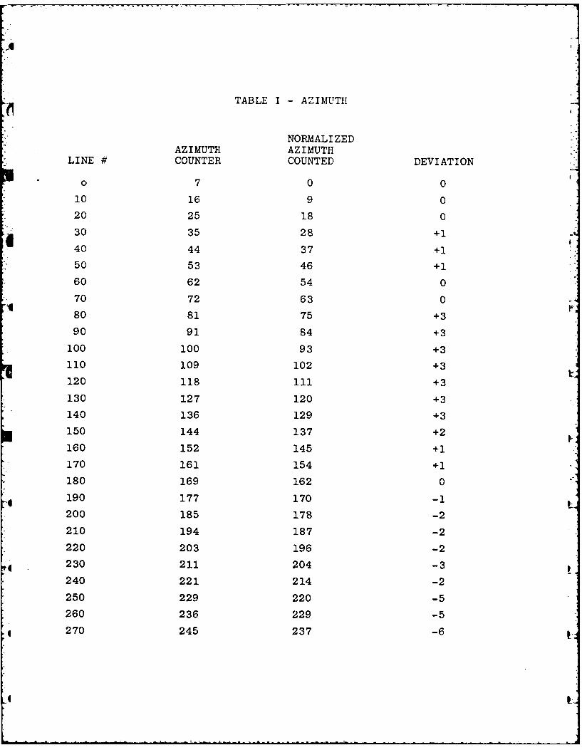
TABLE I - AZIMUTH
NORMALIZEDAZIMUTH AZIMUTH
LINE # COUNTER COUNTED DEVIATION
o 7 0 0
10 16 9 0
20 25 18 0
30 35 28 +1
40 44 37 +1
50 53 46 +1
60 62 54 0
70 72 63 0
80 81 75 +3
90 91 84 +3
100 100 93 +3
110 109 102 +3
120 118 ill +3
130 127 120 +3
140 136 129 +3
150 144 137 +2
160 152 145 +1
170 161 154 +1
180 169 162 0
190 177 170 -1
200 185 178 -2
210 194 187 -2
220 203 196 -2
230 211 204 -3
240 221 214 -2
250 229 220 -5
260 236 229 -5
270 245 237 -6
-
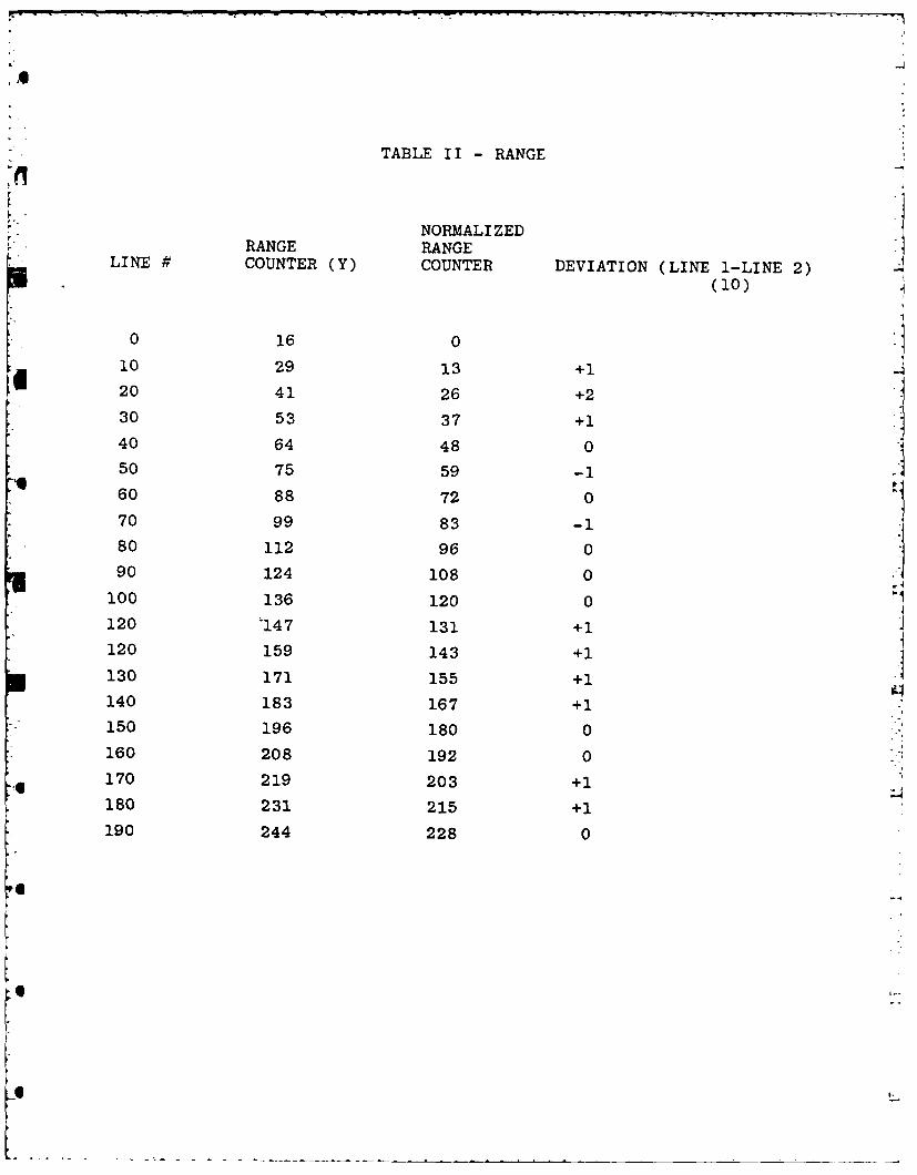
TABLE II - RANGE
NORMALIZEDRANGE RANGE
LINE # COUNTER (Y) COUNTER DEVIATION (LINE 1-LINE 2)(10)
0 16 0
10 29 13 +Ii 20 41 26 +2
30 53 37 +1
40 64 48 0
50 75 59 -160 88 72 0
* 70 99 83 -1* 80 112 96 0
90 124 108 0
100 136 120 0
120 '147 131 +1
120 159 143 +1
130 171 155 +1
140 183 167 +1
150 196 180 0160 208 192 0
170 219 203 +1180 231 215 +1
190 244 228 0
6o
2.17 Video Tape Data Recording Error Rate
In order to make the software resident in the DDM the same
for all scenarios, constants, which vary for each scenario, e.g.,
number of targets, their position and range, etc., are stored on
the non-viewable section of the video recording. This data is
stored as eight bit digital words.
Each word is recorded three times (triple redundancy) with
parity during each video field. Each block (the seven digital words
within a video field) is recorded on two different video fields.
During system operation, the data is read and if a parity error is
sensed, majority voting determines which is the correct data.
Throughout the development phase of the CEV/IVTS system,
various diagnostics were run to determine the recording error rate.
The final conclusion was that if the data was recorded correctly,
there would not be any problems in the data retrievel. The times
that there were problems in reading the data, it was attributed to
a bad initial recording.
ra1
SECTION 3
3.0 Videotape Cassette/Videodisk Comparison
The purpose of this paragraph is to describe and compare
videotape recorders/players and videodisk systems. It should be
understood that day-to-day developments may alter conclusions reachedin this paper.
3.1 Videotape Cassette Recorder/Players
Videotape recording and playback are based on four (4)
principals:
First; a videotape is just a long thin magnet formed from an
iron-oxide powder glued to one side of a plastic tape. The strength
of a magnetic can be varied along its length, a principal that per-
mits the magnetic strength along the length of videotape to be varied.
Second; the magnetic field of a wire wound solenoid can be
varied. The strength of this magnet is proportional to the magnitudeof the current in the solenoid wire.
Third; if the videotape is placed in the solenoid createdmagnetic field it will become magnetized. If the current in the sole-
noid is varied as the videotape is moved across the solenoid surface
the magnetism of the videotape will be varied. To record video on
a magnetic tape the recording head is the solenoid and the current in
the solenoid wire is the information to be recorded.
Fourth; the reverse of the third principal is also true. If
a videotape which has recorded information in the form of magnetism
is pulled past a head or solenoid a current will be induced into the
solenoid wire which represents the magnetic pattern on the tape.
Playback is achieved in this manner.
3.2 Record/Playback
The two main functions of a videotape cassette recorder/
player is recording and playback of a video signal. The input video
signal must be the industry standard and the format used to record
must be used in playback. The helical scan videotape recorder/
player has become the standard machine of the non-broadcast industry.
While there are different models and formats the basic principals
are the same in all helical scan machines. There are certain funda-
mental points which affect the operation of videotape recorder/
player.
* Slant Track Recording
A video picture or frame is composed of two interlaced fields.
The fields are generated sixty times per second and are composed of
262.5 lines which begin at the upper left of the picture tube and
ends at the lower right. The field is shifted and repeated providing
an interlaced video frame which is composed of 525 lines. Each video
field is recorded on a single track which slants across the tape at
approximately 600.
e Servos
The rotating helical scan heads of the video cassette
recorder/player are mounted on a motor-driven shaft which also drives
a device that generates pulses to indicate the position and speed of
the rotating heads. When recording, a constant speed motor drives
the tape and these head reference pulses are recorded evenly spaced
along a control track on the video tape. When the tape is played
back the control pulses are detected and compared to the rotating
head pulses so that the servo system can position the head correctly
in relation to the slant track which is the recorded video field.
* Tape Tension
Tape tension must be the same on playback as it was in record.
If the tape stretches or sags the heads will not scan properly result-ing in synchronization and picture quality problems. Atmosphere con-ditions as well as machine problems can affect tape tension.
3.3 Videodisk
There are at least four incompatible videodisk formats which
are currently available or will be available in the near future. The
formats to be discussed are:
* MCA/PHILLIPS Optical-Laser System
* Thomson-CSF Optical-Laser System
* RCA Capacitance System
* Matsushita/JVC Very High Density (VHD) Capacitance System
3.3.1 MCA/PHILLIPS Optical-Laser System
Television picture and sound information are encoded on the
surface of an optical videodisk in the form of very closely spaced
tracks of microscopic pits. A standard optical videodisk contains
54,000 such tracks, each corresponding to a single television frame.
Spinning at 1800rpm, the MCA/PHILLIPS disk provides 30 minutes of
playing time.
The optical videodisk starts out as a precision ground and
polished glass master. Video and sound signals are placed on appro-
priate PM carriers and combined to form a single PM signal that is
used to modulate a laser beam focused on the photoresist-coated
master.

Once the master has been exposed and developed, the surface
is metalized with a copper coating and subsequently nickel plated to
produce a "mother". This mother is used in making additional copies
by the standard production techniques of injection molding or com-
pression molding.
To playback a MCA/PHILLIPS optical videodisk a helium-neon laser
beam is focused on the surface of the disk and is either weakly or
strongly reflected depending on the presence of a pit at the spot where
the beam is focused.
The system used to play the videodisk is mounted on a preci-
sion mechanical slide that moves the disk to provide course tracking
during normal play and slow motion, and for fast forward and reverse
searches. Exact tracking of the micropits by the laser spot is
achieved by a servo-controlled tracking mirror. During freeze-frame
viewing, this tracking mirror is used to repeatedly switch the laser
spot back to the beginning of the frame track during the vertical
blanking period.
3.3.2 Thomson-CSF Optical-Laser System
To say that the Thomson-CSF videodisk system is the same as
the MCA/PHILLIPS system is unfair and not intended. However, for thepurpose of this paper the video display services to be provided byeach system may be said to have a high commonality. The significant
differences deal with format and a unique feature provided by the
Thomson-CSF system. Both systems have a very shallow depth of focus
which has the advantage of placing dust and scratches on the disk
surface out of focus. This feature is used to an advantage in the
Thomson system which uses a transparent disk. The disk is read by
transmission. The laser beam is diffracted when it passes through
the micropits and is read by photo-electric detectors. With this
system either side of the disk can be read by refocusing the laser
beam.
6'
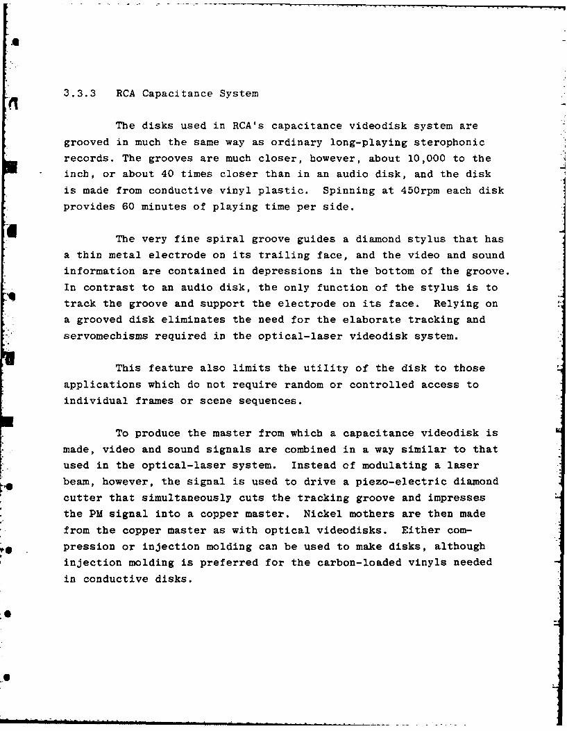
3.3.3 RCA Capacitance System
The disks used in RCA's capacitance videodisk system are
grooved in much the same way as ordinary long-playing sterophonic
records. The grooves are much closer, however, about 10,000 to the
inch, or about 40 times closer than in an audio disk, and the disk
is made from conductive vinyl plastic. Spinning at 450rpm each disk
provides 60 minutes of playing time per side.
The very fine spiral groove guides a diamond stylus that has
a thin metal electrode on its trailing face, and the video and sound
information are contained in depressions in the bottom of the groove.
In contrast to an audio disk, the only function of the stylus is to
track the groove and support the electrode on its face. Relying on
a grooved disk eliminates the need for the elaborate tracking and
servomechisms required in the optical-laser videodisk system.
This feature also limits the utility of the disk to those
applications which do not require random or controlled access to
individual frames or scene sequences.
To produce the master from which a capacitance videodisk is
made, video and sound signals are combined in a way similar to that
used in the optical-laser system. Instead of modulating a laser
beam, however, the signal is used to drive a piezo-electric diamond
cutter that simultaneously cuts the tracking groove and impresses
the PM signal into a copper master. Nickel mothers are then madefrom the copper master as with optical videodisks. Either com-
pression or injection molding can be used to make disks, although
injection molding is preferred for the carbon-loaded vinyls needed
in conductive disks.

3.3.4 Matsushita/JVC VHD System
The Matsushita/JVC video high-density (VHD) system uses the
same capacitive detection scheme as RCA's, however, the disks are
quite different. The disks resemble those used in the optical-laser
system and are made in much the same way - from laser-exposed photo-
resist-coated glass masters. In contrast to the optical system where
the pits are sensed by a reflected or diffracted laser beam, the VHD
system uses a conductive vinyl disk and senses the pits capacitively.
Since there are no grooves in the disk to guide the stylus, additional
pits are located alongside the main signal to provide tracking signals
to the electrode stylus. These signals are used to drive the servo-
controlled arm that carries the stylus. Capacitive pickups can resolve
signal elements significantly smaller than the wavelength of light.
The VHD system puts one hour of television programming on one side of
a 10-inch disk.
It is claimed that the grooveless disk gives the VHD system
at least the same flexibility as the optical-laser disk system with
less complexity. Slow motion, fast foward and reverse, freeze frame
and random access are purported to be possible with this system.
3.4 Comparison of Videotape to Videodisks
An objective analysis of the values of one system over another
is almost impossible. While the videodisk has many desirable featuresnot readily available in non-broadcast tape recorder/players consumerdemand and competition in the Educational Videotape area has resulted
in the evolution of videotape machine features. External processor
control, random frame access and freeze frame (pause) are now or will
soon be available in Sony and Panasonic machines. Conversely it is
reasonable to assume that low price optical disk mastering system may
soon be offered. This constant evolution of product features and a
certain emotionalism exhibited by advocates of one or the other systemtends to confuse and reduce the value of any analysis.
*~A
4J+d 0. r-Q4
(tzi *0 &.4 C 1 .00l 0 Ic Q) 0 3.-d
-4 = a) . 0 >
*.>40. 4 d -*CU 0 a0a)Ev C (vC)VC 0-V~ C)C4 w -CEW041S-
0. : -40 0 -4 ~-4 L)-~floQ) V0 UC V > 0w m Q) w)r4.) 0)54 (12 02 00.Vr a cw0 m0 4- 004 cC -CC) c0C)' r. E 54 r -0 C L C) 04~e )~ -r4" 4 .
V 2 0w owm414J'0S V4)~ w4-O u Q2"4 CU OCd - 0 r-4 " 0 4C .0 Cd ) xCd -)Cd0 -4
'a -0 a 0) -f-0 4 CU rC r 1 0CdU4- )~ 4.)0. 0*-4 i -40
k " CU a) k5420 0. 0
+3 05 cd Cd a54) 410 k C -fIC 0. $4 * 4JC
w O)0+) C~Cd~)C .0
0o 1, 0 . Cd 0 r- 00"4) 0V0 0 0~'0$" 4 a) E OCd EV0 0)Q) 4Jr-I 0 V00= 0.= 0
54 k 4 r- .0 41 Q) cr4)C.>.0~- 4 Cdt-H4- U r4 0 4)0
0 0-5 04- M "- ) C 0 CD CdCd '44-0 Q0r.4- r 41) ft
4-4 E 0 $4 0 ( 4 U)0) V-H .)+) 5q05140 U~ 0..!4bO cUU0 >. W. C4-)0. .CUCW -4 4--) 0 W.C0 CUCa) xQ
o U)o4- ~CUI=4-).00c Cd I= -
00.94-a
;>o-
04 Fok -)$
Cd0 "-I 0 b0 2 43 0
54 (D 0 C.)IO5
CV) CU C) 00

$.4 4-) C.4 O 0 Q 4- 0
~ )4-1 -d
E.D 0U k $.I-~ ~ 0. x
Q) Q) C x0Ud ) 0> r= a) 0 > 0 cd 4-
B2 -0H. E
4-)= 1 W C 4- WE0 =
0 V 0r4 w. C)0 dC)04-)
Q) 0 "-.v4 0.w Q) Q W-4Q)C =- ) )4.41 4 > > -.04 Vd 4o-) CO .0 4- )
o~~~~ UQ dc4~.C)~"- 0SiCC -CH
0 W 4v W W- 4J kE r.~CV1~ 4-)0' E) C) C) ")~- 0).~rCC (E> WW - N k >-4- 4-)+W.- Q-
a)04 Hl )0 4.) -E E 0) 4 c -4 0 M M '0 Cd (C 4-cd -Ha) 4- CJ k 0 w .0V 0 wC . +-j it
k -)M 0 a) - JWP )c 1 c4- C - 4 IH C)E 44Ec0 Q) r
. rEt bD4 0' >>wVUV4H 04-)bO a 0)0 w k 0 r-4 0 4- 4)
(n 4- C4) (4-4 w C 4-) 0W 0 C 44- 0 -0H -H~~ a) 4- C 0 4 :+)W z E ICU10 t) mC14 0 . 4-1 V QO) m k r
0 U a)bDC = >,= t Q) HS .r- r4
(D. 04S rzE -4 * b.-U0W 4-U ) ) -4-) 0 -
k 0vC 'U 's- a)0 4 0" 0 4'> Cd 40 0 4- J b o d-
o C +3 -t-4 0~~4 W W )' v PC0 kwk -C) u.2 -H.- to 0 "- (L) 4-4 bO 0 )0dW&
fd ( 0CH 0. 0W V%- C)4U-4O) -H 4wW'U 4-2 EU r.C a) '40 E )0. -- Zk1
Uc E ME 1 0 wOE0 '0 E +)0.- 4 -H~b ..C) D) (D0 r- 4-q- -4 0c r. 0.0 U
>4 W44 4- >C CC WE 4-)4 W0- O V -H- E0V4- r
cC 0dV) 0 r. a
QU CU U) CdC)w .- be - b4 k
po cC 0 k bO- Cd >U 0. 0- E
0d .0 fr PL4 0 0 -
'U w. o 4-) 4) ii a) 00N 0 kC 1) C3 r- C)-r
a) E .0: k 0D 0 (D )Ck C )V C
Cd C) Cd 0 Cfv4 >C VHk 41~k- k- k- '-I Q) a) PQ 0 >4- C
;L 6 n ca m U 0V
3.6 Comments
As can be seen any judgement on the utility of either system
would have to be based on the intended application. It is practical
to consider videotape in any training system development phase even
if a disk will be the ultimate video storage medium as long as the
unique features of the disk are not an essential part of system
parameters. In many instances where there is a low target population
the videotape is probably as cost effective as the videodisk. Con-
versely, where the target population is high the disk is always the
best choice as is the case where rapid frame accessability is neces-
sary.
*L
SECTION 4
4.1 Recommended Changes
Sanders' recommends that the following changes be imple-
mented in the pre-production model of the CEV/IVTS system:
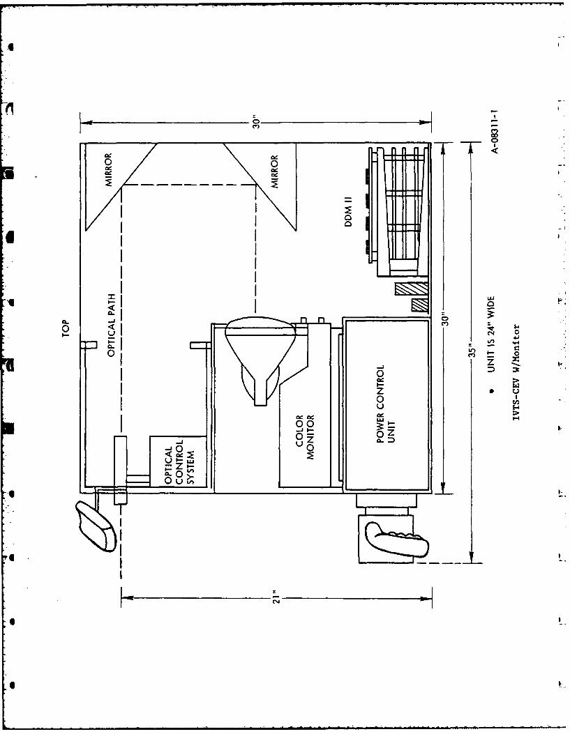
4.1.1 Decrease physical size of the system as shown in Figure 1.
4.1.2 Incorporate a 9" color monitor as part of the system. Thisadaptation simplifies the optics system, increases transportability,
ensures alignment between optics and visual scene and reduces surface
area requirement for system set-up.
4.1.3 Replace Apple computer with more rugged and reliable 8085
based computer system. The Apple computer was selected to ease soft-
ware development and on-site test and debug. While this computer is
an excellent tool for a professional it will not survide constant
transport and rough handling without extensive modification. Sanders'
8085 based system is designed to meet military requirements and will
cost less than the Apple when produced in number.
4.1.4 Implement machine gun training capabilities. Tracer graphics
will be implemented in software which responds to the machine gun
switch selection.
4.1.5 The thickness of the reticle lines in the optical system
should be decreased by 50%.
4.1.6 Install a head rest which moves with telescope. The head
rest should position the students eye for the same eye relief as the
actual system.
4.1.7 ElE;':Lion controls should be loose - decrease torque by 50%.
4.1.8 Azimuth control should have zero torque at zero and 75%
less torque, over remaining travel (when the azimuth control is acti-
vated it should oscillate to simulate actual equipment).
4.1.9 Dead zone (hand control) in both azimuth and elevation is
approximately + 15 degrees.
4.1.10 Install a second audio input such that the instructor (tank
commander) can use a helmet or microphone for scenario control insteadof using the audio on the VTR. Provide a switch to permit the instruc-
tor to select either source.
4.1.11 Make calibration 600 meters instead of 500 meters (bore
sighting is done at 600 meters in vehicle).
4.1.12 Display the correct impact point on the target. This can
be implemented by allowing the student to request that a small circle("0") could be overlayed on the scene at each impact point.
4.1.13 Display and range (in meters) and cant (in mils) for each
impact point by student request.
4.1.14 Use audible sounds for student feedback to indicate proximity
of burst to correct impact point. One pip indicates outer edge of
acceptable impact zone, two pips indicates half distance between outer
edge and perfect hit and three pips indicates perfect hit.
4.1.15 Replace the potentiometer position detection devices with an
optical raster scan line position detection system. Currently the
position of the optics relative to the scene is electromechanically
measured using potentiometers. This scheme requires tha.t the optical
system and the video display be critically aligned; a condition that
will be hard to maintain in a transportable training device. By
using an electro-optical scheme the system measures the aim point by
optically determining alignment to the CRT raster lines doing away
with the need for critical mechanical alignment.
4.1.16 Enhance audio simulation to provide firing sounds which are
closer to actual system.
4.1.17 Enhance audible "up" report by loader.
.0I
II1
00
0 1 z0 >
'I Ia. I _ _ _.E-
-jo-0
Z: .I--CL 0
(N
5.0 Recommended Application of IVTS Technology
Follow-on application of IVTS technology to military train-
ing can include any system which requires a high quality visual repre-
sentation of real-world target parameters and concurrent interaction
between the trainee and the scene. The following two systems are con-
sidered prime candidates for this application. The M60 Machinegun
and follow-on Squad Automatic Weapons (SAW) don't have a training
system which provides effective feedback on the fundamental skills of
position and grip, sight alinement and sight picture, trigger manipu-
lation and zeroing the weapon. Mortar indirect fire trainers are
normally configured for institutional classroom use and as such are
not available at unit level. An application which provides observed
fire training at unit level should also be considered.
5.1 Machinegun Training
FM23-67 indicates that M60 Machinegun training is conducted
on basic and transition ranges where fundamentals of machinegun marks-
manship are learned, followed by field target firing courses where
the individual applies these fundamentals against typical battlefield
targets. Maintenance of proficiency at unit level is essentially the
same as indicated above except that ammunition expenditure on basic
and transition ranges is reduced.
Ammunition expenditure to accomplish this training is as follows:
MARKSMANSHIP TRAINING ROUNDS
* Basic Range (10 meters) 336
e Transition Range 276
* Field Target Courses 450
TOTAL 1062
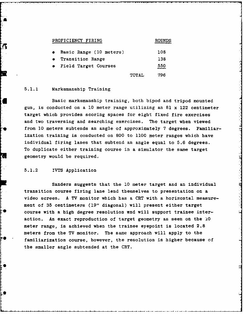
PROFICIENCY FIRING ROUNDS
e Basic Range (10 meters) 108
* Transition Range 138
9 Field Target Courses 550
TOTAL 796
5.1.1 Marksmanship Training
Basic marksmanship training, both bipod and tripod mounted
gun, is conducted on a 10 meter range utilizing an 81 x 122 centimeter
target which provides scoring spaces for eight fixed fire exercises
and two traversing and searching exercises. The target when viewed
from 10 meters subtends an angle of approximately 7 degrees. Familiar-
ization training is conducted on 800 to 1100 meter ranges which have
individual firing lanes that subtend an angle equal to 5.6 degrees.
To duplicate either training course in a simulator the same target
geometry would be required.
5.1.2 IVTS Application
Sanders suggests that the 10 meter target and an individual
transition course firing lane lend themselves to presentation on a
video screen. A TV monitor which has a CRT with a horizontal measure-
ment of 35 centimeters (19" diagonal) will present either targetcourse with a high degree resolution and will support trainee inter-
action. An exact reproduction of target geometry as seen on the 10
meter range, is achieved when the trainee eyepoint is located 2.8
meters from the TV monitor. The same approach will apply to the
familiarization course, however, the resolution is higher because of
the smaller angle subtended at the CRT.
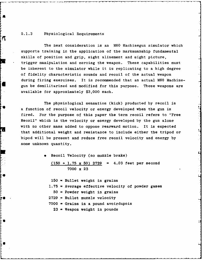
5.1.3 Physiological Requirements
The next consideration is an M60 Machinegun simulator which
supports training in the application of the marksmanship fundamental
skills of position and grip, sight alinement and sight picture,
trigger manipulation and zeroing the weapon. These capabilities must
be inherent to the simulator while it is replicating to a high degree
of fidelity characteristic sounds and recoil of the actual weapon
during firing exercises. It is recommended that an actual M60 Machine-
gun be demilitarized and modified for this purpose. These weapons are
available for approximately $3,000 each.
The physiological sensation (kick) producted by recoil is
a function of recoil velocity or energy developed when the gun is
fired. For the purpose of this paper the term recoil refers to "Free
Recoil" which is the velocity or energy developed by the gun alone
with no other mass added to oppose rearward motion. It is expected
that additional weight and resistance to include either the tripod or
bipod will be present and reduce free recoil velocity and energy by
some unknown quantity.
* Recoil Velocity (no muzzle brake)
(150 + 1.75 x 50) 2729 = 4.03 feet per second
7000 x 23
150 = Bullet weight in grains
1.75 = Average effective velocity of powder gases
50 = Powder weight in grains
2729 = Bullet muzzle velocity
7000 = Grains in a pound avoirdupois
23 = Weapon weight in pounds

9 Recoil Energy
.5 x 23 x 4.032 = 5.8 foot pounds32.16
Simulation of weapon recoil must also take into considera-
tion recoil velocity rise time which in the case of the M60 is probably
on the order of one millisecond or greater due to its weight. Sanders
suggests introducing recoil (kick) directly into the barrel group, at
the bipod yoke, for the bipod mounted weapon. Introduction of recoil
at this point would ensure azimuth and elevation motion freedom and,
if desired, permits extension of the recoil simulator mechanism to
actuate the operating rod and provide automatic feed and ejection of
belt feed dummy ammunition.. Introduction of recoil for the tripod
mounted gun would be at the gun platform and if desired the forearm
assembly would be modified to provide access to the operating rod for
automatic dummy ammunition feed and ejection.
5.1.4 Sound
Sound effects will be generated using a solid state device
which produces high-quality electronically synthesized machinegun
sounds. Sound would be presented to the trainee through a high fidel-
ity head set which provides the additional feature of maintaining
classroom noise at very low levels.
5.1.5 Aim Point Measurement
Measurement of trainee aim point, trainee feedback (bullet
impact), and comparison of bullet impact to desired impact point are
the essential elements necessary to complete the training system.
Sanders' IVTS is designed to measure trainee aim point relative to a
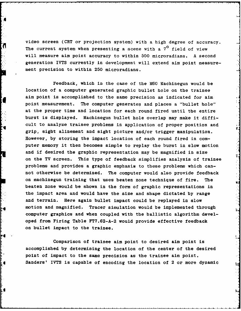
video screen (CRT or projection system) with a high degree of accuracy.
The current system when presenting a scene with a 70 field of view
will measure aim point accuracy to within 500 microradians. A second
generation IVTS currently in development will extend aim point measure-
ment precision to within 250 microradians.
Feedback, which in the case of the M60 Machinegun would be
location of a computer generated graphic bullet hole on the trainee
aim point is accomplished to the same precision as indicated for aim
point measurement. The computer generates and places a "bullet hole"
at the proper time and location for each round fired until the entire
burst is displayed. Machinegun bullet hole overlap may make it diffi-
cult to analyze trainee problems in application of proper position and
grip, sight alinement and sight picture and/or trigger manipulation.
However, by storing the impact location of each round fired in com-
puter memory it then becomes simple to replay the burst in slow motion
and if desired the graphic representation may be magnified in size
on the TV screen. This type of feedback simplifies analysis of trainee
problems and provides a graphic emphasis to these problems which can-
not otherwise be determined. The computer would also provide feedback
on machinegun training that uses beaten zone technique of fire. The
beaten zone would be shown in the form of graphic representations in
the impact area and would have the size and shape dictated by range
and terrain. Here again bullet impact could be replayed in slow
motion and magnified. Tracer simulation would be implemented through
computer graphics and when coupled with the ballistic algorithm devel-
oped from Firing Table FT7.62-A-2 would provide effective feedback
on bullet impact to the trainee.
4Comparison of trainee aim point to desired aim point is
accomplished by determining the location of the center of the desired
point of impact to the same precision as the trainee aim point.
Sanders' IVTS is capable of encoding the location of 2 or more dynamic
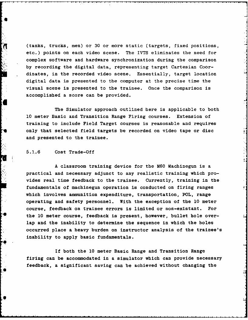
(tanks, trucks, men) or 30 or more static (targets, fixed positions,
etc.) points on each video scene. The IVTS eliminates the need for
complex software and hardware synchronization during the comparison
by recording the digital data, representing target Cartesian Coor-
dinates, in the recorded video scene. Essentially, target location
digital data is presented to the computer at the precise time the
visual scene is presented to the trainee. Once the comparison is
accomplished a score can be provided.
The Simulator approach outlined here is applicable to both
10 meter Basic and Transition Range Firing courses. Extension of
training to include Field Target courses is reasonable and requires
only that selected field targets be recorded on video tape or disc
and presented to the trainee.
5.1.6 Cost Trade-Off
A classroom training device for the M60 Machinegun is a
practical and necessary adjunct to any realistic training which pro-
vides real time feedback to the trainee. Currently, training in the
fundamentals of machinegun operation is conducted on firing ranges
which involves ammunition expenditure, transportation, POL, range
operating and safety personnel. With the exception of the 10 meter
course, feedback on trainee errors is limited or non-existant. For
the 10 meter course, feedback is present, however, bullet hole over-
lap and the inability to determine the sequence in which the holes
occurred place a heavy burden on instructor analysis of the trainee's
inability to apply basic fundamentals.
If both the 10 meter Basic Range and Transition Range
firing can be accommodated in a simulator which can provide necessary
feedback, a significant saving can be achieved without changing the
existing overall training program. Assume that at least 2000 indi-
viduals in the Army and the Marine Corps fire Basic and Transition
Courses on a monthly basis:
858 Rounds
x 2000 Individuals1,716,000 Total Rounds/Month
x .25 Cost of Round on 4:1 Tracer to Ball Mix$429,000 Cost per Month
x 12 Months
$5,148,000 Annual Cost
As can be seen there can be significant savings in the
machinegun or the Squad Automatic Weapons (SAW) training programs.
This approach does not change existing firing courses which have
proved successful over an extended period of time. It simply sub-
stitutes the medium that is used in the basic and transition training.
Sanders' classroom Interactive Video Training System
when mated with an M60 Machinegun simulator as described herein will
provide realistic training with graphic feedback that ensures easy
analysis of trainee problems. Accomplished in a classroom, or for
that matter any type of room, the training is not impacted by weather
and requires only a common 110 volt 60Hz outlet. No other consumables
are required.
High fidelity feedback provided by Sanders' IVTS ensures
that when the trainee reaches a point in simulator training where he
has qualified to actually fire an M60 Machinegun he and his instructors
can concentrate on achieving a higher level of proficiency with a
reduction in the expenditure of ammunition and other consumables.
5.2 Mortar Gunnery Training Device (IVTS)
LII
4J
5.2.1 Mortar Gunnery Problem
FM23-91 defines the mortar gunnery problem as follows:
"Mortars are normally emplaced in defilade to conceal them
from the enemy. For the vast majority of targets placing the mortars
in defilade precludes sighting the weapons directly at the target
(direct lay), consequently, indirect fire must be employed to attack
the targets. The gunnery problem is primarily the problem of indirect
fire and the solution of this problem requires weapon and ammunition
settings which, when applied to the weapon and the ammunition, will
cause the projectile to burst on, or at a proper height, above the
target. The steps in the solution of the gunnery problem are:
a. Location of the target and mortar positions
b. Determination of chart data (direction, range and
vertical interval from mortars to target)
c. Conversion of chart data to firing data
d. Application of firing data to the weapon and the
ammunition."
Location of the target is accomplished by the forward
observer who follows a standard procedure sequence for processing a
call for mortar fire. This sequence is as follows:
a. Target location
b. Preparation and submission of the call for fire
c. Adjustment of fire
5.2.2 Target Presentation
To perform target location the observer must have the target
area in view and be capable of measuring (1) distance from his point
to the target; direction to the target; target deviation from a knownpoint (horizontal and vertical). Presentation of the mortar target
-4t

area on a video screen is reasonable. Consider the observer's prime
angle measuring device; the military binocular which has a horizontal
and vertical mil scale etched on the reticle. These binoculars typi-
cally have a seven degree field of view. If these binoculars are
located at 2.8 meters away from the TV monitor the video image field
will fill the binocular field of view. Control of the recorded image
field of view will now provide apparent range changes e.g., the dia-
meter of a seven degree field of view at 1000 meters is 120 meters
and a 4 meter target equals three percent of the FOV diameter. At
2000 meters the field of view diameter is 240 meters and the same
target represents 1.5 percent of the field of view. By maintaining
control of the diameter of the recorded scene field of view the ob-
server is presented with a target area that can be measured using
standard military binocular MIL scales. Target location within the
target area scene can now be accomplished to the same precision as
"real world" target location.
5.2.3 Estimation of Distance
Distance can be computed by measuring the angle from one
point in the video scene to another with the binocular MIL scale. The
trainee refers to a MAP training aid which indicates the lateral dis-
tance and he then applies the MIL relation formula. He may also esti-
mate distance by establishing a yardstick in the video scene by asking
the microcomputer to fire three rounds into the video scene with known
range separation between rounds. The computer accepts the request
from the observer and places a mortar burst symbol at the location
requested for the first round and at timed intervals displays mortar
burst symbols at the requested range separation points. The trainee
may also wish to estimate range by timing sound. The microcomputer
will always present the burst symbol and then delay the computer gen-
erated sound based on the simulated range to the burst point.
5.2.4 Measurement of Angles
The trainee can measure angles (both vertical and horizontal)
within the video scene using the binocular MIL scale and map training
aids which relate. to the objects or terrain features within each
scene.
As can be seen this approach will utilize existing training
aids such as standard military binoculars, observed fire fans andcoordinate scales. The high quality cues presented in the video
scene will elicit necessary responses from the trainee and ensure
training in target location. The call for fire may be processed
through a manual fire direction center or a simulated Mortar Ballis-
tics Computer, XM23.
5.2.5 Call for Fire, Manual FDC
The trainee observer performs target location and communi-
cates his fire request to FDC trainees who use existing training aids
to convert data contained in the observer call for fire to firing data
and commands for the trainee's at the mortar section. If the training
system includes a mortar with a sight unit that has been modified so
that the IVTS microcomputer can monitor elevation and deflection
settings then deflection and elevation data can be told directly to
the mortar crew who in turn will set this data in the sight unit. It
will be necessary to enter mortar charge data directly into the IVTS
microcomputer through the keyboard. When the dummy round is droppedinto the tube the computer detects this condition and computes time
* * of flight, location of the simulated burst in the scene, and time of
explosion sound. Scoring can be readily accomplished as the computer
will know the actual location of the target point.
"I.
If the training system does not include a mortar that has
been appropriately modified or if training of the mortar crew is not
desired at this time the FDC trainee's may enter elevation, deflection
and charge data directly into the IVTS microcomputer.
5.2.6 Call for Fire, Mortar Computer Ballistic's XM-23
The only requirement to implement this training as part of
the IVTS system is to simulate the Ballistic computer front panel
controls and indicators and connect the panel to the IVTS microcomputer.
The IVTS microcomputer would perform all the ballistic computations
and communicate appropriate indications to the trainee. In this case
scoring would include proper operation of the Ballistic computer.
Adjustment of fire is accomplished when the trainee observer
senses the impact of the mortar round computer generated burst in the
video scene. It has been demonstrated that computer generated burst
symbols overlaid on proper segments of the video scene will provide
measureable feedback on range and azimuth displacement from the
desired point of impact. Using his military binoculars the trainee
measures the displacement and initiates an adjusted call for fire
through the FDC. Training in adjustment of fire from an aircraft can
also be implemented with Sanders' IVTS as it represents only a change
in view of the target area. Video scenes taken from an aircraft can
be coded to accomplish this training.
5.2.7 Training System
As can be seen the three major elements of mortar gunnery
target location, fire lirection, and application of firing data to the
weapon can be trained in a classroom using a video based system which
can score the trainees and provide realistic feedback.
~1

With proper design the training system can be conditioned
to support one or two elements of indirect fire team training. As
an example the system should be capable of being conditioned to accept
target location data and providing appropriate feedback to the trainee
observer or FDC or mortar crew without the need for the other crew
members.

IJ
ADDENDUM I
Field # Data Block
1 Start of New Scenario
2 Blank (No Data)
3 Start of New Scenario
4 Blank
5 Static Data #1
6 Blank
7 Static Data #2
8 Blank
p Static Data #N
p+l Blank
p+2 Start of New Scenario
p+3 Blank
p+4 Start of New Scenario
p+5 Blank
p+6 Static Data #1
p+7 Blank
p+8 Static Data #2
q
q+l Static Data #N
q+2 Blank
q+3 Static Dynamic
q+4 Static Dynamic
q+5 Dynamic Data #1
q+6 Dynamic Data #2
q+7 Dynamic Data #N
I ~ i m dulu mt d ~ m h' mm~ -
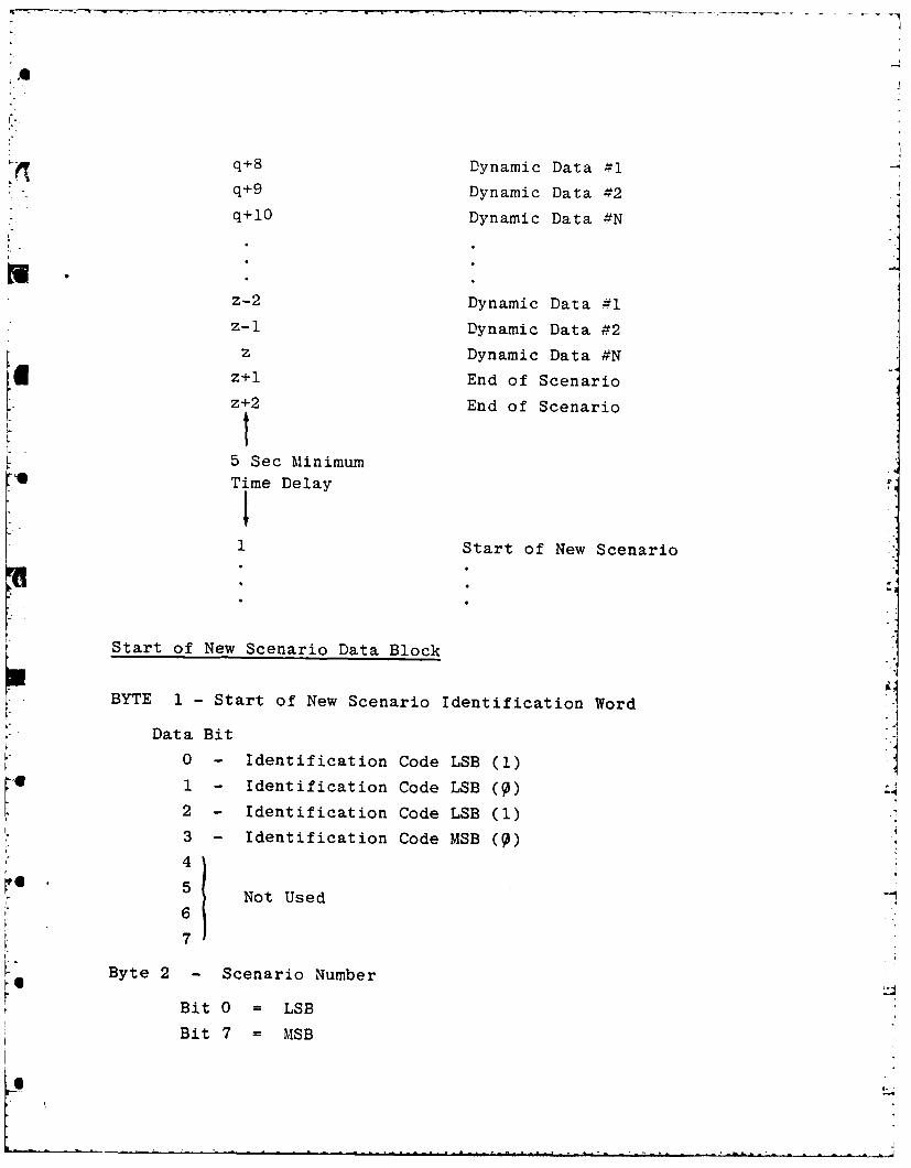
q D D .- l
q+9 Dynamic Data #2* q+9 Dynamic Data #2*. q+10 Dynamic Data N
j
z-2 Dynamic Data #1z-1 Dynamic Data #2
z Dynamic Data #N
Z+l End of Scenario
z+2 End of Scenario
5 Sec MinimumTime Delay
Sf
cStart of New Scenario Data Block
BYTE 1 - Start of New Scenario Identification Word
Data Bit
0 - Identification Code LSB (1)
1 - Identification Code LSB ( )
2 - Identification Code LSB (1)3 - Identification Code MSB ( )4
5.Not Used6
7
Byte 2 - Scenario Number
Bit 0 = LSBBit 7 = MSBBi 7=•S
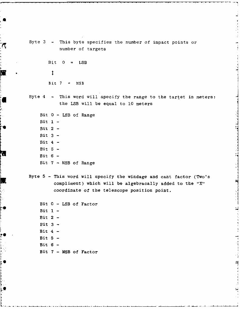
Byte 3 This byte specifies the number of impact points or
number of targets
Bit 0 = LSB
Bit 7 - MSB
Byte 4 - This word will specify the range to the tartet in meters!the LSB will be equal to 10 meters
Bit 0 - LSB of Range IBit 1-
Bit 2 -
Bit 3 -
Bit 4 -
Bit 5 -Bit 6 -
Bit 7 - MSB of Range
Byte 5 - This word will specify the windage and cant factor (Two's
compliment) which will be algebracally added to the "X"
coordinate of the telescope position point.
Bit 0 - LSB of Factor
Bit 1-
Bit 2 -
Bit 3 -
Bit 4 -
Bit 5 -
Bit 6 -
Bit 7 - MSB of Factor
4

Byte 6-
Bit 0 - Number of Requested Rounds - LSB
Bit 1 - Number of Requested Rounds - LSB
Bit 2 - Number of Requested Rounds - LSB
Bit 3 - Number of Requested Rounds - MSB
Bit 4 -
Bit 5 -
Bit 6-Bit 7 - This bit will specify whether the tank commander or the
gunner will perform the "BOT" function. A "zero" speci-
fies that it will be a gunner "BOT".
Byte 7 - Not used
Static and Dynamic Data Blocks
The Byte format for the "Static Data" and "Dynamic Data" blocks
is the same the only difference (except for the bit which specifies
a dynamic or static target) is their position in the code stream.
Byte 1 - Identifier Word
Bit 0 - Identifier Code LSB (1)
Bit 1 - Identifier Code LSB (9)
Bit 2 - Identifier Code LSB (9)
Bit 3 - Identifier Code MSB (9)
Bit 4 - Target Number 24
Bit 5 - Target Number 25
Bit 6 - Target Number 26
Bit 7 - Target Number 27
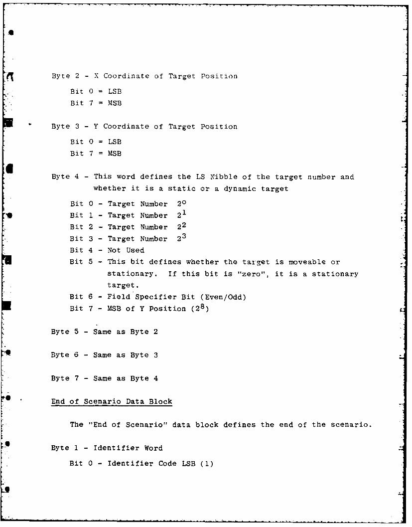
Byte 2 - X Coordinate of Target Position
Bit 0 =LSB
Bit 7 = MSB
Byte 3- Y Coordinate of Target Position
Bit 0 = LSB
Bit 7 = MSB
Byte 4 - This word defines the LS Nibble of the target number and
whether it is a static or a dynamic target
Bit 0 - Target Number 20
Bit 1 - Target Number 21
Bit 2 - Target Number 22
Bit 3 - Target Number 2
Bit 4 - Not Used
Bit 5 - This bit defines whether the target is moveable or
stationary. If this bit is "zero", it is a stationary
target.
Bit 6 - Field Specifier Bit (Even/Odd)
Bit 7 - MSB of Y Position (28)
Byte 5 -Same as Byte 2
Byte 6 - Same as Byte 3
Byte 7 - Same as Byte 4
End of Scenario Data Block
The "End of Scenario" data block defines the end of the scenario.
Byte 1 - Identifier Word
Bit 0 - Identifier Code LSB (1)
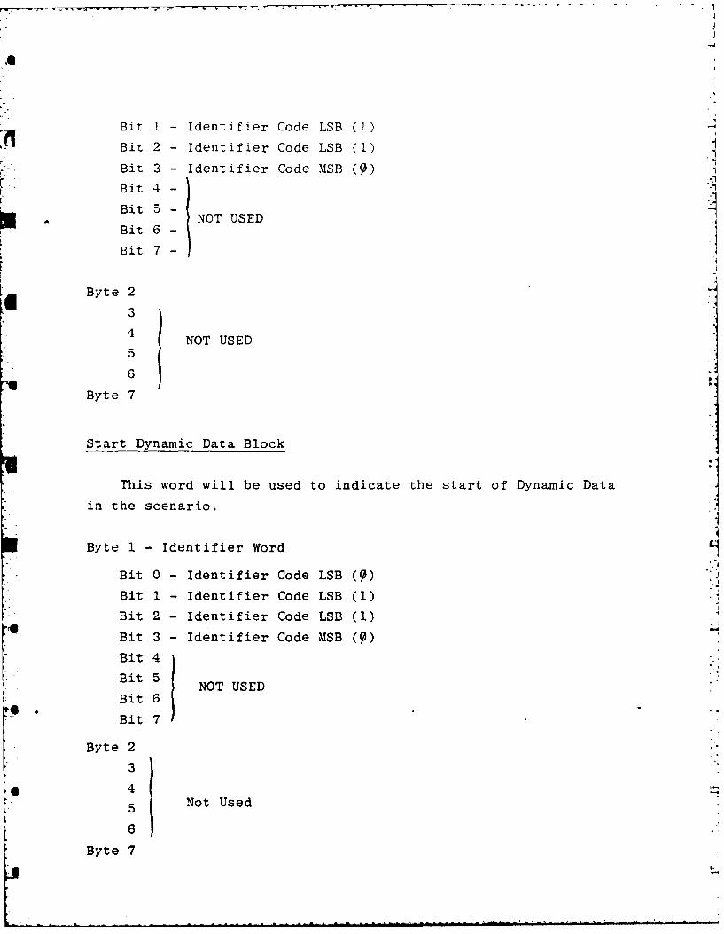
Bit 1 - Identifier Code LSB (1)
Bit 2 - Identifier Code LSB (1)
Bit 3 - Identifier Code MSB (1)
Bit 4 -
Bit 5 -NOT USED
Bit 6 -
Bit 7-
Byte 23
4 ~ NOT USED5
6
Byte 7
Start Dynamic Data Block
This word will be used to indicate the start of Dynamic Data
in the scenario.
Byte 1 - Identifier Word
Bit 0 - Identifier Code LSB ( )
Bit 1 - Identifier Code LSB (1)
Bit 2 - Identifier Code LSB (1)
Bit 3 - Identifier Code MSB ( )
Bit 4
Bit 5
Bit 6 NOT USED
Bit 7
Byte 2
3
4
5 Not Used
6
Byte 7
lot;
Alk
* *46
'24 .0 %q
~kfr
Yi.~ I 1l
h4-
*~ ~ ~ l '14P p? -
4;> *1 , -9
IL
-' r 1(44 .. ~1$