mn280043en substation frame knova59-1 and … · substation frame knova59-1 and knova59-3 assembly...
TRANSCRIPT
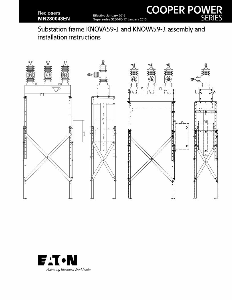
Substation frame KNOVA59-1 and KNOVA59-3 assembly and installation instructions
OP
EN
COOPER POWERSERIES
Reclosers MN280043EN
Effective January 2016Supersedes S280-85-17 January 2013

ii SUBSTATION FRAME KNOVA59-1 AND KNOVA59-3 ASSEMBLY AND INSTALLATION INSTRUCTIONS MN280043EN January 2016
DISCLAIMER OF WARRANTIES AND LIMITATION OF LIABILITY
The information, recommendations, descriptions and safety notations in this document are based on Eaton Corporation’s (“Eaton”) experience and judgment and may not cover all contingencies. If further information is required, an Eaton sales office should be consulted. Sale of the product shown in this literature is subject to the terms and conditions outlined in appropriate Eaton selling policies or other contractual agreement between Eaton and the purchaser.
THERE ARE NO UNDERSTANDINGS, AGREEMENTS, WARRANTIES, EXPRESSED OR IMPLIED, INCLUDING WARRANTIES OF FITNESS FOR A PARTICULAR PURPOSE OR MERCHANTABILITY, OTHER THAN THOSE SPECIFICALLY SET OUT IN ANY EXISTING CONTRACT BETWEEN THE PARTIES. ANY SUCH CONTRACT STATES THE ENTIRE OBLIGATION OF EATON. THE CONTENTS OF THIS DOCUMENT SHALL NOT BECOME PART OF OR MODIFY ANY CONTRACT BETWEEN THE PARTIES.
In no event will Eaton be responsible to the purchaser or user in contract, in tort (including negligence), strict liability or other-wise for any special, indirect, incidental or consequential damage or loss whatsoever, including but not limited to damage or loss of use of equipment, plant or power system, cost of capital, loss of power, additional expenses in the use of existing power facilities, or claims against the purchaser or user by its customers resulting from the use of the information, recom-mendations and descriptions contained herein. The information contained in this manual is subject to change without notice.

iiiSUBSTATION FRAME KNOVA59-1 AND KNOVA59-3 ASSEMBLY AND INSTALLATION INSTRUCTIONS MN280043EN January 2016
Contents
SAFETY INFORMATIONSafety Information . . . . . . . . . . . . . . . . . . . . . . . . . . . . . . . . . . . . . . . . . . . . . . . . . . . . . . . . . . . . . . . . . . . . . . . . . . . . . iv
PRODUCT INFORMATIONIntroduction . . . . . . . . . . . . . . . . . . . . . . . . . . . . . . . . . . . . . . . . . . . . . . . . . . . . . . . . . . . . . . . . . . . . . . . . . . . . . . . . . . .1
Acceptance and initial inspection . . . . . . . . . . . . . . . . . . . . . . . . . . . . . . . . . . . . . . . . . . . . . . . . . . . . . . . . . . . . . . . . . . .1
Handling and storage . . . . . . . . . . . . . . . . . . . . . . . . . . . . . . . . . . . . . . . . . . . . . . . . . . . . . . . . . . . . . . . . . . . . . . . . . . . .1
Standards . . . . . . . . . . . . . . . . . . . . . . . . . . . . . . . . . . . . . . . . . . . . . . . . . . . . . . . . . . . . . . . . . . . . . . . . . . . . . . . . . . . . .1
Description of frame. . . . . . . . . . . . . . . . . . . . . . . . . . . . . . . . . . . . . . . . . . . . . . . . . . . . . . . . . . . . . . . . . . . . . . . . . . . . .1
INSTALLATION DIMENSIONSCheck recloser ratings prior to installation . . . . . . . . . . . . . . . . . . . . . . . . . . . . . . . . . . . . . . . . . . . . . . . . . . . . . . . . . . . .2
FRAME FOUNDATION . . . . . . . . . . . . . . . . . . . . . . . . . . . . . . . . . . . . . . . . . . . . . . . . . . . . . . . . . . . . . . . . . . . . . . . . . . . . . .3
FRAME PARTS AND ASSEMBLYGeneral directions . . . . . . . . . . . . . . . . . . . . . . . . . . . . . . . . . . . . . . . . . . . . . . . . . . . . . . . . . . . . . . . . . . . . . . . . . . . . . .4
Frame height . . . . . . . . . . . . . . . . . . . . . . . . . . . . . . . . . . . . . . . . . . . . . . . . . . . . . . . . . . . . . . . . . . . . . . . . . . . . . . . . . .5
Assembly and installation parts . . . . . . . . . . . . . . . . . . . . . . . . . . . . . . . . . . . . . . . . . . . . . . . . . . . . . . . . . . . . . . . . . . . .5
Frame assembly . . . . . . . . . . . . . . . . . . . . . . . . . . . . . . . . . . . . . . . . . . . . . . . . . . . . . . . . . . . . . . . . . . . . . . . . . . . . . . . .7
FRAME INSTALLATION . . . . . . . . . . . . . . . . . . . . . . . . . . . . . . . . . . . . . . . . . . . . . . . . . . . . . . . . . . . . . . . . . . . . . . . . . . . . .9
CONTROL INSTALLATION. . . . . . . . . . . . . . . . . . . . . . . . . . . . . . . . . . . . . . . . . . . . . . . . . . . . . . . . . . . . . . . . . . . . . . . . . . 11
SWITCHGEAR INSTALLATIONNOVA recloser, DAS switch, VCS-3 switch, and TVS sectionalizer installation. . . . . . . . . . . . . . . . . . . . . . . . . . . . . . . . 11
NOVA STS recloser installation . . . . . . . . . . . . . . . . . . . . . . . . . . . . . . . . . . . . . . . . . . . . . . . . . . . . . . . 12

iv SUBSTATION FRAME KNOVA59-1 AND KNOVA59-3 ASSEMBLY AND INSTALLATION INSTRUCTIONS MN280043EN January 2016
The instructions in this manual are not intended as a substitute for proper training or adequate experience in the safe operation of the equipment described. Only competent technicians who are familiar with this equipment should install, operate, and service it.
A competent technician has these qualifications:
• Is thoroughly familiar with these instructions.
• Is trained in industry-accepted high and low-voltage safe operating practices and procedures.
• Is trained and authorized to energize, de-energize, clear, and ground power distribution equipment.
• Is trained in the care and use of protective equipment such as arc flash clothing, safety glasses, face shield, hard hat, rubber gloves, clampstick, hotstick, etc.
Following is important safety information. For safe installa-tion and operation of this equipment, be sure to read and understand all cautions and warnings.
Safety instructionsFollowing are general caution and warning statements that apply to this equipment. Additional statements, related to specific tasks and procedures, are located throughout the manual.
Safety for life!
SAFETYFOR LIFE
!SAFETYFOR LIFE
Eaton meets or exceeds all applicable industry standards relating to product safety in its Cooper Power™ series products. We actively promote safe practices in the use and maintenance of our products through our service literature, instructional training programs, and the continuous efforts of all Eaton employees involved in product design, manufacture, marketing, and service.
We strongly urge that you always follow all locally approved safety procedures and safety instructions when working around high voltage lines and equipment, and support our “Safety For Life” mission.
Safety information
DANGERHazardous voltage. Contact with hazardous voltage will cause death or severe personal injury. Follow all locally approved safety procedures when working around high- and low-voltage lines and equipment. G103.3
WARNING Before installing, operating, maintaining, or testing this equipment, carefully read and understand the contents of this manual. Improper operation, handling or maintenance can result in death, severe personal injury, and equipment damage. G101.0
WARNING This equipment is not intended to protect human life. Follow all locally approved procedures and safety practices when installing or operating this equipment. Failure to comply can result in death, severe personal injury and equipment damage. G102.1
WARNING Power distribution and transmission equipment must be properly selected for the intended application. It must be installed and serviced by competent personnel who have been trained and understand proper safety procedures. These instructions are written for such personnel and are not a substitute for adequate training and experience in safety procedures. Failure to properly select, install or maintain power distribution and transmission equipment can result in death, severe personal injury, and equipment damage. G122.3
This manual may contain four types of hazard statements:
DANGER Indicates an imminently hazardous situation which, if not avoided, will result in death or serious injury.
WARNING Indicates a potentially hazardous situation which, if not avoided, could result in death or serious injury.
CAUTION Indicates a potentially hazardous situation which, if not avoided, may result in minor or moderate injury.
CAUTIONIndicates a potentially hazardous situation which, if not avoided, may result in equipment damage only.
Hazard Statement Definitions

Product information
IntroductionEaton's Service Information MN280043EN provides assembly and installation instructions for its Cooper Power™ series KNOVA59-1 and KNOVA59-3 substation frames. It contains a convenient step-by-step explanation of installation procedures as well as a parts list. Before assembling the frame, carefully read and understand the contents of this manual.
Read this manual firstRead and understand the contents of this manual and follow all locally approved procedures and safety practices before installing or operating this equipment.
Additional informationThese instructions cannot cover all details or vari ations in the equipment, procedures, or process described nor provide directions for meeting every possible contin gency during installation, operation, or maintenance. For additional information, please contact your Eaton representative.
Acceptance and initial inspectionAll frame parts are inspected at the factory. They are in good condition when accepted by the carrier for shipment.
Upon receipt, inspect the shipping container for signs of damage. Unpack and inspect thoroughly for damage incurred during shipment. If damage is discovered, file a claim with the carrier immediately.
Handling and storageBe careful during handling and storage of the frame to mini-mize the possibility of damage. If the frame is to be stored for any length of time prior to assembly or installation, provide a clean, dry storage area.
Quality standardsISO 9001 Certified Quality Management System
Description of frameThe substation frame referenced in these instructions is intended for the following switchgear:
• NOVA® Three-Phase, Microprocessor-Controlled Recloser
• DAS Three-Phase, Vacuum-Break Distribution Automation Switch
• VCS-3 Three-Phase, Vacuum-Break Capacitor Switch
• TVS Time-Voltage Sectionalizer
• NOVA STS Three-Phase, Microprocessor-Controlled Recloser
The galvanized frame is constructed of rigid structural or formed steel. The hardware is stainless steel. Practical, welded construction is used to provide a high degree of rigidity with minimum weight. The substation frame height is adjustable to satisfy a variety of application conditions.
1SUBSTATION FRAME KNOVA59-1 AND KNOVA59-3 ASSEMBLY AND INSTALLATION INSTRUCTIONS MN280043EN January 2016

Figure 1. Substation mounting dimensions for NOVA recloser, DAS switch, VCS-3 switch, and TVS sectionalizer.
2216(87.25)
adjustable to2826
(111.25) in
76 (3)increments
1060(41.75)
965(38)
457(18)
552(21.75)
19 (0.75)Mounting Hole (4)
B
OP
EN
C
A
Step 1Items 9, 13,
and 14
Step 1Items 9, 13,
and 14
Installation dimensions
otee:N All dimensions are mm (inches). Dimensions shown are approximate.
UNIT TYPE RatingA (at minimum height) B C
NOVA Recloser 15 kV (110 kV BIL) 3124 (123) 908 (35.75) 508 (20)
15 kV (125 kV BIL) 3180 (125.25) 964 (38) 564 (22.25)
27 kV (125 kV BIL) 3180 (125.25) 964 (38) 564 (22.25)
27 kV (150 kV BIL) 3279 (129) 1063 (41.75) 663 (26)
38 kV 3279 (129) 1063 (41.75) 663 (26)
DAS Switch
without CT
15 kV 3067 (120.75) 851 (33.5) 508 (20)
27 kV 3128 (123.25) 911 (36) 569 (22.5)
DAS Switch
with CT
15 kV (110 kV BIL) 3124 (123) 908 (35.75) 508 (20)
15 kV (125 kV BIL) 3180 (125.25) 964 (38) 564 (22.25)
27 kV (125 kV BIL) 3180 (125.25) 964 (38) 564 (22.25)
27 kV (150 kV BIL) 3279 (129) 1063 (41.75) 663 (26)
38 kV 3279 (129) 1063 (41.75) 663 (26)
VCS-3 Switch 15 kV 3067 (120.75) 851 (33.5) 508 (20)
27 kV 3128 (123.25) 911 (36) 569 (22.5)
2 SUBSTATION FRAME KNOVA59-1 AND KNOVA59-3 ASSEMBLY AND INSTALLATION INSTRUCTIONS MN280043EN January 2016

Figure 2. Substation mounting dimensions for NOVA STS recloser.
otee:N All dimensions are mm (inches). Dimensions shown are approximate.
UNIT TYPE RatingA (at minimum height) B C
NOVA STS Recloser 15 kV (110 kV BIL) 3124 (123) 908 (35.75) 508 (20)
27 kV (125 kV BIL) 3180 (125.25) 964 (38) 564 (22.25)
38 kV 3279 (129) 1063 (41.75) 663 (26)
965(38)
C
B
A
1060(41.75)
2216(87.25)
adjustable to2826
(111.25) in
76 (3)increments
457(18)
552(21.75)
19 (0.75)Mounting Hole (4)
Step 1Items 9, 13,
and 14
Step 1Items 9, 13,
and 14
3SUBSTATION FRAME KNOVA59-1 AND KNOVA59-3 ASSEMBLY AND INSTALLATION INSTRUCTIONS MN280043EN January 2016

Frame foundation
A mounting pad must be constructed for proper support of the switchgear and substation frame. Concrete slabs can be fabricated by a local concrete products firm. See the dimensions in the plan and profile views of Figure 3. The overall weight of the substation frame is approximately 118 kg (260 lbs).
Figure 3. Location of anchoring holes and hardware in substation frame mounting pad.
Profile View
203 mm (8 in)
203 mm (8 in)
Plan View457 mm (18 in)
1371 mm (54 in)
965 mm (38 in)
457 mm(18 in)
102 mm (4 in)
152 mm (6 in)
51 mm (2 in) min.
Finished Grade
Bevel 25 mm (1 in)
Welded Wire Fabric Reinforcement(102 mm (4") squares of No. 13 wire min.)
16mm (5/8") Threaded Insert
16 mm (5/8") std galvanized machine bolt and flat washer (alternative anchoring method)
4 SUBSTATION FRAME KNOVA59-1 AND KNOVA59-3 ASSEMBLY AND INSTALLATION INSTRUCTIONS MN280043EN January 2016

Frame parts and assembly
General directionsCoat the frame hardware with anti-seize compound (Item 20) before assembling. Connect the hardware securely during assembly, then tighten firmly after securing the frame on the mounting pad.
Frame heightThe upper posts as assembled to the lower posts determine the frame height. The range of frame-heights is shown in Figures 1 and 2 and Table 1. The amount of required overlap (upper post inside lower post) to obtain the desired frame height is shown in Table 1.
Assembly and installation partsCarefully unpack, separate, and identify the various parts. See Table 2 for the KNOVA59-1 Substation Frame for NOVA recloser, DAS switch, VCS-3 switch, and TVS sectionalizer. See Table 3 for the KNOVA59-3 Substation Frame for NOVA STS recloser.
Table 1. Frame Heights and Overlap
Frame Heightmm (inches)
Overlapmm (inches)
2216 (87.25) 724 (28.5)
2292 (90.25) 648 (25.5)
2369 (93.25) 572 (22.5)
2445 (96.25) 495 (19.5)
2521 (99.25) 419 (16.5)
2597 (102.25) 343 (13.5)
2673 (105.25) 267 (10.5)
2750 (108.25) 191 (7.5)
2826 (111.25) 114 (4.5)
Table 2. KNOVA59-1 Substation Assembly and Installation Parts
Item Description Part Number Quantity
1 Support Angle VCS10011860001 5
2 Upper post, left 6A00378601 2
3 Upper post, right 6A00378602 2
4 Lower post, right RA01152001 2
5 Lower post, left RA01152002 2
6 Cross brace, short R001533002 4
7 Cross brace, long R001533008 4
8 Control mounting strap KM00001366X000 1
9 Hex-head cap screw, 1/2-13 X 1.25” 730115150125A 34
10 Hex-head cap screw, 1/2-13 X 1.50” 730115150150A 4
11 Hex-head cap screw, 1/2-13 X 1.75” 730115150175A 10
12 Hex-head cap screw, 1/2-13 X 2.5” 730115150250A 2
13 Hex nut, 1/2-13 880215113050A 50
14 Spring lockwasher, 1/2-med 900815050000A 50
15 Washer 900215050000A 2
16 Spacer KA20280061 12
17 Caplug bolt cover .5” KA20730057 2
18 Caplug retainer, .5” KA20730058 2
20 Anti-seize compound KA23640017 3
IMPORTANT Determine the desired frame height and required overlap before beginning. This will affect the assembly process for the substation frame.
5SUBSTATION FRAME KNOVA59-1 AND KNOVA59-3 ASSEMBLY AND INSTALLATION INSTRUCTIONS MN280043EN January 2016

Table 3. KNOVA59-3 Substation Assembly and Installation Parts
Item Description Part Number Quantity
1 Support Angle VCS10011860001 5
2 Upper post, left 6A00378601 2
3 Upper post, right 6A00378602 2
4 Lower post, right RA01152001 2
5 Lower post, left RA01152002 2
6 Cross brace, short R001533002 4
7 Cross brace, long R001533008 4
8 Control mounting strap KM00001366X000 1
9 Hex-head cap screw, 1/2-13 X 1.25” 730115150125A 32
10 Hex-head cap screw, 1/2-13 X 1.50” 730115150150A 16
11 Hex-head cap screw, 1/2-13 X 1.75” 730115150175A 10
12 Hex-head cap screw, 1/2-13 X 2.5” 730115150250A 2
13 Hex nut, 1/2-13 880215113050A 48
14 Spring lockwasher, 1/2-med 900815050000A 60
15 Washer 900215050000A 2
16 Spacer KA20280061 12
17 Caplug bolt cover .5” KA20730057 2
18 Caplug retainer, .5” KA20730058 2
19 Mounting bracket 6A00432602 2
20 Anti-seize compound KA23640017 3
6 SUBSTATION FRAME KNOVA59-1 AND KNOVA59-3 ASSEMBLY AND INSTALLATION INSTRUCTIONS MN280043EN January 2016

Frame assemblyDo not tighten the bolts while assembling the frame to allow for spacer placement and frame adjustments. Tighten all bolts securely when assembly is completed.
1. Overlap the upper and lower posts (Figure 4) as needed to obtain the desired height of the frame. See the Frame Height section of this manual.
A. Attach one upper post, left (Item 2) to one lower post, left (Item 5) with 1.25” hex head capscrews (Item 9), and secure with lockwashers (Item 14) and .5” hex nuts (Item 13). See Figure 1 or 2.
B. Attach one upper post, right (Item 3) to one lower post, right (Item 4) with 1.25” hex head capscrews (Item 9), and secure with lockwashers (Item 14) and .5” hex nuts (Item 13). See Figure 1 or 2.
2. Overlap the remaining upper and lower posts as determined in step 1 while attaching the support angle (Item 1).
A. Attach support angles (Item 1) to the remaining upper posts (Items 2 and 3) and lower posts (Items 4 and 5) with 1.75” hex head capscrews (Item 11), with a spacer (Item 16) between the upper and lower posts, and secure with lockwashers (Item 14) and .5” hex nuts (Item 13). The caplug retainer (Item 18) and caplug bolt cover (Item 17) are installed in the Item 1, 2, and 5 connection. See Figure 5.
B. Secure the upper posts (Items 2 and 3) and lower posts (Items 4 and 5) with 1.25” hex head capscrews (Item 9), and secure with lockwashers (Item 14) and .5” hex nuts (Item 13). See Figures 4 and 6.
Figure 4. Attaching upper post to lower post.
OVERLAP
OVERLAP
LOWERPOST (Items 4 or 5)
UPPERPOST (Items 2 or 3)
14
13
9
Figure 5. Attaching support angle Item 1 to upper and lower posts.
OVERLAP
UPPERPOST (Items 2 or 3)
OVERLAP
LOWERPOST (Items 4 or 5)
13
14
16
11
SUPPORTANGLE(Item 1)
18
17
Figure 6. Securing upper and lower posts.
SUPPORTANGLE(Item 1)
UPPERFRAMEPOST (Items 2 or 3)
Items 9, 11, and 13
7SUBSTATION FRAME KNOVA59-1 AND KNOVA59-3 ASSEMBLY AND INSTALLATION INSTRUCTIONS MN280043EN January 2016

3. Attach the upper ends of the short cross braces (Item 6) to the upper posts (Items 2 and 3) and lower posts (Items 4 and 5). Use 1.75” hex head capscrews (Item 11), with a spacer (Item 16) between the upper and lower posts. Secure with lockwashers (Item 14) and .5” hex nuts (Item 13). See Figures 7 and 9.
4. Attach the lower ends of the short cross braces (Item 6) to the lower posts (Items 4 and 5) with 1.25” hex head capscrews (Item 9), and secure with lockwashers (Item 14) and .5” hex nuts (Item 13). See Figures 8 and 9.
5. Attach the short cross braces (Item 6) at their midpoint with 1.25” hex head capscrews (Item 9), and secure with lockwashers (Item 14) and .5” hex nuts (Item 13). See Figure 8 and 9.
6. Attach two support angles (Item 1) to the upper ends of the upper posts (Items 2 and 3) and one support angle on the control side of the assembly with 1.25” hex head capscrews (Item 9), and secure with lockwashers (Item 14) and .5” hex nuts (Item 13). See Figures 9 and 10. Place control-support angle 533 mm (21“) above lower support angle, measured screw to screw.
Figure 9. Assembling narrow side of frame.
9, 13, 14
9, 13, 14
3
1
6
2
4
5400mm (15.75 in)
9, 13, 14
11, 13, 14, 16 11, 13, 14, 16
1
Step 3
Step 4
Step 5
Step 6
Figure 7. Attaching short cross brace (Item 6).
11
6
16
14
13
LOWERPOST(Items 4 or 5)
UPPERPOST(Items 2 or 3)
Figure 8. Assembling frame with Items 9, 13, and 14.
FRAME
9
FRAME13
14
Figure 10. Attaching support angle (Item 1) to upper post.
9
ANGLE SUPPORT(Item 1)
14
13
UPPERPOST(Items 2 or 3)
9
14
13 Control-side only
8 SUBSTATION FRAME KNOVA59-1 AND KNOVA59-3 ASSEMBLY AND INSTALLATION INSTRUCTIONS MN280043EN January 2016

7. Attach the upper ends of the long cross braces (Item 7) to the upper posts (Items 2 and 3) and lower posts (Items 4 and 5). Use 1.50” hex head capscrews (Item 10), and secure with lockwashers (Item 14) and .5” hex nuts (Item 13). See Figure 11.
8. Attach the lower ends of the long cross braces (Item 7) to the lower posts (Items 4 and 5), with 1.25” hex head capscrews (Item 9), and secure with lockwashers (Item 14) and .5” hex nuts (Item 13). See Figure 11.
9. Attach the long cross braces (Item 7) at their midpoint with 1.25” hex head capscrews (Item 9), and secure with lockwashers (Item 14) and .5” hex nuts (Item 13) See Figure 11.
10. Check frame alignment and securely tighten all nuts and screws.
Frame installation
Install the substation frame on the constructed mounting pad. See the Frame Foundation section of this manual. Firmly tighten all of the substation assembly hardware after attaching the frame to the mounting pad. See Figure 12.
Figure 11. Attaching long cross braces (Item 7).
59, 13, 14
7
10, 13, 14
400 mm(15.75 in)
9, 13, 14
4
4
5
Figure 12. Installing substation frame on mounting pad.
552 mm(21.75 in)
457 mm(18 in)
1060 mm (41.75 in)
965 mm (38 in)
19 mm (3/4") Holes for 16 mm (5/8") Anchor Bolts
Item 4
Item 4
Item 5Item 5
9SUBSTATION FRAME KNOVA59-1 AND KNOVA59-3 ASSEMBLY AND INSTALLATION INSTRUCTIONS MN280043EN January 2016

Control installation
Attach the control mounting strap (Item 8) to either one of the narrow frame sides. See Figures 13 and 14.
1. Attach the control mounting strap (Item 8), at the hole 13 mm (.5 in) from the end (this is the top end), to the middle support angle (Item 1) with 1.75” hex head capscrews (Item 11). Secure with lockwashers (Item 14) and .5” hex nuts (Item 13). Use two spacers (Item 16); placement is determined by control type.
2. Attach the control mounting strap (Item 8), through the hole 26.75” from the top end of the strap, to the lower support angle (Item 1) with 1.75” hex head capscrews (Item 11). Secure with lockwashers (Item 14) and .5” hex nuts (Item 13). Use two spacers (Item 16); placement is determined by control type.
3. Mount the control to the control mounting strap (Item 8). Measure the strap to determine where to mount the control. Use 2.5” hex head capscrews (Item 12) and washers (Item 15), and secure with lockwashers (Item 14) and .5” hex nuts (Item 13). See Figures 13, 14, and 15.
Figure 15. Attaching control to mounting strap (Item 8).
12
1514
13
CONTROL MOUNTING STRAP(Item 8)
CONTROL BRACKET
286 (11.25)
368 (14.5)
876 (34.5)
927 (36.5)
1016 (40)
Attach to frame 13 (.5)
Attach to frame 679 (26.75)
Type Form 6 and Form 4C(double-size cabinet)
940 (37)
Type FXA, FXB,and
Form 4C (single-size
cabinet)511 (20.125)
Type Form 6665 (26.25)
76 (3)
Dimensions shown: Top-to-hole on left, mounting holes on right.All dimensions are mm (in). (Dimensions approximate).
Type Form 5640 (25.25)
260 (10.25)
Figure 14. Control mounting strap (Item 8). (Only stan-dard control mounting locations are shown.)
Figure 13. Attaching control mounting strap (Item 8) to sub-station frame.
11, 13, 14, 16;See detail.
11, 13, 14, 16;See detail.
Item 1
Item 1
Item 8
12, 13, 14, 15
12, 13, 14, 15
For Form 4, Form 5, and Pole-Mount Form 6:
For Rack-Mount Form 6:
10 SUBSTATION FRAME KNOVA59-1 AND KNOVA59-3 ASSEMBLY AND INSTALLATION INSTRUCTIONS MN280043EN January 2016

Switchgear installation
NOVA recloser, DAS switch, VCS-3 switch, and TVS sectionalizer installation
Refer to the appropriate manual for complete installation instructions as follows:
• S260-60-1 DAS15, DAS27, and DAS38 Three-Phase Vacuum-Break Distribution Automation Switch Installation and Operation Instructions
• S260-62-1 VCS-3 Three-Phase Vacuum-Break Capacitor Switch Installation and Operation Instructions
• S270-30-1 TVS15, TVS27, and TVS38 Time-Voltage Sectionalizer Installation and Operation Instructions
• S280-42-1 NOVA15, NOVA27, and NOVA38 Three-Phase Microprocessor-Controlled Installation and Operation Instructions
Mount the switchgear to the substation frame on both sides to support angles (Item 1). Use 1.25” hex head capscrews (Item 9) and secure with lockwashers (Item 14) and .5” hex nuts (Item 13). See Figures 1 and 17.
Figure 17. Attaching NOVA recloser, DAS switch, VCS-3 switch, or TVS sectionalizer to substation frame.
9, 13, 14
Item 1
Figure 16. Lifting instructions for the switchgear.
OP
EN
CLOSE
A
Cg
B
LiftingLugs
Moving the switchgearThe switchgear is shipped palletized (bolted onto a pallet). When moving with a fork truck/lift, the switchgear must remain bolted to the pallet to avoid damage to the contact position indicator.
Lifting the switchgearFollow all approved safety practices when making hitches and lifting the equipment. Lift the unit smoothly and do not allow the unit to shift.
A: Sling height for 15 kV and 27 kV with 125 BIL units: 914 mm (36 in) Sling height for 27 kV with 150 BIL and 38 kV units: 1067 mm (42 in)
B: Center of gravity (Cg) is approximately 100 mm (4 in) below plane of lower terminals.
WARNING Falling equipment. Use the lifting lugs provided and follow all locally approved safety practices when lifting and mounting the equipment. Lift the unit smoothly and do not allow the unit to shift. Improper lifting can result in severe personal injury, death, and/or equipment damage. G106.3
CAUTION Personal injury. Sheds on epoxy encapsulation have sharp edges. Wear protective gloves when handling the unit. Failure to do so can result in cuts and abrasions. T258.1
CAUTION Tip-over hazard. High center of gravity. The substation frame is a top-heavy structure with the switchgear mounted. Secure the substation frame to the mounting pad before mounting the switchgear. Failure to comply can cause the unit to tip over, damaging the frame and switchgear. T300.0
CAUTION Tip-over hazard. High center of gravity. Use a 4-point hitch to prevent switchgear from overturning during lift-ing operations. Improper lifting can result in personal injury or equipment damage. T297.0
11SUBSTATION FRAME KNOVA59-1 AND KNOVA59-3 ASSEMBLY AND INSTALLATION INSTRUCTIONS MN280043EN January 2016

NOVA STS recloser installation Refer to the appropriate manual for complete installation instructions as follows:
• S280-44-1 NOVA-STS15, NOVA-STS 27, and NOVA-STS 38 Three-Phase Microprocessor-Controlled Installation and Operation Instructions
Mount the bracket (Item 19) to the substation frame on both sides to support angles (Item 1). Use 1.25” hex head capscrews (Item 9) and secure with lockwashers (Item 14) and .5” hex nuts (Item 13).
Mount the recloser to the bracket. Use 1.25” hex head capscrew (Item 10) and lockwasher (Item 14). See Figures 2 and 19.
OP
EN
CLOSE
A
Cg
B
LiftingLugs
OP
EN
OP
EN
Moving the switchgearThe switchgear is shipped palletized (bolted onto a pallet). When moving with a fork truck/lift, the switchgear must remain bolted to the pallet to avoid damage to the contact position indicator.
Lifting the switchgearFollow all approved safety practices when making hitches and lifting the equipment. Lift the unit smoothly and do not allow the unit to shift.
A: Sling height for 15 kV and 27 kV with 125 BIL units: 914 mm (36 in) Sling height for 27 kV with 150 BIL and 38 kV units: 1067 mm (42 in)
B: Center of gravity (Cg) is approximately 100 mm (4 in) below plane of lower terminals.
Figure 19. Attaching NOVA STS recloser to substation frame.
10, 14
9, 13, 14Item 19
Item 1
Figure 18. Lifting instructions for the switchgear.
CAUTION Tip-over hazard. High center of gravity. Use a 4-point hitch to prevent switchgear from overturning during lifting operations. Improper lifting can result in personal injury or equipment damage. T297.0
12 SUBSTATION FRAME KNOVA59-1 AND KNOVA59-3 ASSEMBLY AND INSTALLATION INSTRUCTIONS MN280043EN January 2016

13SUBSTATION FRAME KNOVA59-1 AND KNOVA59-3 ASSEMBLY AND INSTALLATION INSTRUCTIONS MN280043EN January 2016
This page is intentionally left blank.

14 SUBSTATION FRAME KNOVA59-1 AND KNOVA59-3 ASSEMBLY AND INSTALLATION INSTRUCTIONS MN280043EN January 2016
This page is intentionally left blank.

15SUBSTATION FRAME KNOVA59-1 AND KNOVA59-3 ASSEMBLY AND INSTALLATION INSTRUCTIONS MN280043EN January 2016
This page is intentionally left blank.
Eaton1000 Eaton BoulevardCleveland, OH 44122United StatesEaton.com
Eaton’s Cooper Power Systems Division2300 Badger DriveWaukesha, WI 53188United StatesEaton.com/cooperpowerseries
© 2016 EatonAll Rights ReservedPrinted in USAPublication No. MN280043EN KA2048-471 Rev. 05
Eaton is a registered trademark.
All trademarks are property of their respective owners.
For Eaton's Cooper Power series product information call 1-877-277-4636 or visit: www.eaton.com/cooperpowerseries.
!SAFETYFOR LIFE