mo-201 electric power distribution · pdf filethis manual on electric power distribution...
TRANSCRIPT
Naval Facilities Engineering Command 200 Stovall Street
Alexandria, Virginia 22332-2300
Electric Power Distribution Systems
Operations
NAVFAC MO-201 April 1990
SN 0525-LP-320-1900
FOREWORD
This manual on electric power distribution systems is one of a series developed to aid utilitysupervisory personnel at shore establishments in the performance of their duties. It includesinformation obtained from extensive research of current literature on the subject and preferredpractices based on practical experience. The principles and procedures described are inaccordance with national professional society, association, and institute codes.
Additional information concerning procedures, suggestions, recommendations ormodifications that will improve this manual are invited and should be submitted throughappropriate channels to the Commander, Naval Facilities Engineering Command, (Attention: Code 165), 200 Stovall Street, Alexandria, VA 22332-2300.
This publication has been reviewed and approved in accordance with the Secretary of theNavy Instruction 5600.16A and is certified as an official publication of the Naval FacilitiesEngineering Command. It cancels and supersedes Operation of Electric Power DistributionSystems, NAVFAC MO-201, November 1963, in its entirety.
D. B. CAMPBELL Assistant Commander for Public Works Centers and Departments
i

PAGE ii INTENTIONALLY LEFT BLANK

ABSTRACT
Application principles and procedures for the operation of electric power distribution systemsand associated major apparatus are presented. The contents include principles of power systems,cabling systems, electrical equipment, power system protection and coordination, instrumentsand meters, operational procedures, and electrical utilization systems.
iii

PAGE iv INTENTIONALLY LEFT BLANK

CHANGE CONTROL SHEET
Document all changes, page replacements, and pen and ink alterations posted in this manual.
AMENDMENT AMENDMENTNUMBER DATE
POST DATE POSTED BY(LAST NAME)
V

PAGE vi INTENTIONALLY LEFT BLANK

CONTENTS PAGE
CHAPTER 1 PRINCIPLES OF POWER SYSTEMS 1-1 1.1 Typical Power Network............................................................................ 1-1 1.2 Electric Power Generation........................................................................ 1-2 1.3 Alternating Current Power Transmission System.................................... 1-3 1.4 Primary Distribution Systems................................................................... 1-4 1.5 Secondary Distribution Systems............................................................... 1-9 1.6 Emergency and Standby Power Systems.................................................. 1-15
CHAPTER 2 POWER DISTRIBUTION CABLE SYSTEMS 2-1 2.1 Cable Specifications................................................................................. 2-1 2.2 Cable Construction................................................................................... 2-1 2.3 Cable Ratings and Selection Criteria........................................................ 2-5 2.4 Types of Cable Installations..................................................................... 2-7 2.5 Power System Applications...................................................................... 2-10
CHAPTER 3 POWER SYSTEM ELECTRICAL EQUIPMENT 3-1 3.1 Major Apparatus....................................................................................... 3-1 3.2 Transformers............................................................................................. 3-2 3.3 Voltage Regulators.................................................................................... 3-16 3.4 Switches.................................................................................................... 3-21 3.5 Circuit Breakers........................................................................................ 3-26 3.6 Automatic Circuit Reclosers..................................................................... 3-38 3.7 Power Capacitors...................................................................................... 3-44 3.8 Distribution Substation............................................................................. 3-53
CHAPTER 4 POWER SYSTEM PROTECTION AND COORDINATION 4-1 4.1 System Protection Methods...................................................................... 4-1 4.2 Short-Circuit Currents.............................................................................. 4-2 4.3 Relays....................................................................................................... 4-8 4.4 Applied Protective Relaying.................................................................... 4-15 4.5 Fuses........................................................................................................ 4-19 4.6 Low-Voltage Circuit Breakers................................................................. 4-25 4.7 System Coordination Study..................................................................... 4-28
CHAPTER 5 POWER SYSTEM INSTRUMENTS AND METERS 5-1 5.1 Instrumentation and Metering.................................................................. 5-1 5.2 Instruments............................................................................................... 5-3 5.3 Meters....................................................................................................... 5-6
vii

CONTENTS (continued) PAGE
CHAPTER 6 POWER SYSTEM OPERATION 6-1 6.1 Power System Structure........................................................................... 6-1 6.2 Control Center Procedures....................................................................... 6-2 6.3 Switchboards............................................................................................ 6-5 6.4 Safety and Environmental Requirements................................................. 6-8
CHAPTER 7 ELECTRICAL UTILIZATION SYSTEMS 7-1 7.1 System Voltages....................................................................................... 7-1 7.2 Equipment Nameplate Ratings and Nominal System Voltages................ 7-1 7.3 Street Lighting Systems............................................................................ 7-3
CHAPTER 8 MANAGING THE OPERATION OF ELECTRICAL DISTRIBUTION SYSTEMS 8-1
8.1 Operations Overview................................................................................. 8-1 8.2 Operations Management............................................................................ 8-1 8.3 Maintenance Management......................................................................... 8-9 8.4 System Planning Studies............................................................................ 8-14
CHAPTER 9 NEW AND EMERGING TECHNOLOGY 9-1 9.1 Supervisory Control and Data Acquisition................................................ 9-1 9.2 Control Circuits and Devices..................................................................... 9-4 9.3 Cogeneration.............................................................................................. 9-6 9.4 Variable Speed Electric Drive Systems..................................................... 9-7
APPENDIX A Operating Responsibilities and Organizational Relationships...... A-1
BIBLIOGRAPHY.................................................................................... Bibliography-1
INDEX................................................................................................................. Index-1
viii
FIGURES
FIGURE NO. TITLE PAGE
1-1 Typical Electric Power Generation, Transmission, and Distribution System.............. 1-11-2 Typical Distribution Substation Arrangements............................................................ 1-51-3 Typical Bus Arrangements........................................................................................... 1-71-4 Four Primary Feeder Arrangements............................................................................. 1-81-5 Conventional Simple-Radial Distribution System....................................................... 1-111-6 Expanded Radial Distribution System......................................................................... 1-111-7 Primary Selective Distribution System........................................................................ 1-121-8 Loop Primary-Radial Distribution System................................................................... 1-121-9 Secondary Selective-Radial Distribution System......................................................... 1-141-10 Secondary Network Distribution System..................................................................... 1-141-11 Secondary Banking Distribution System..................................................................... 1-161-12 Engine Generators (Parallel Operation)....................................................................... 1-201-13 Peak Load Control System........................................................................................... 1-201-14 Combined Utility-Generator System............................................................................ 1-201-15 Rotating Flywheel No Break System........................................................................... 1-241-16 Nonredundant UPS System.......................................................................................... 1-251-17 Nonredundant UPS System with Static Bypass........................................................... 1-251-18 Redundant UPS System............................................................................................... 1-263-1 Delta-Wye..................................................................................................................... 3-83-2 Wye-Delta..................................................................................................................... 3-83-3 Wye-Wye...................................................................................................................... 3-93-4 Delta-Delta.................................................................................................................... 3-93-5 Zigzag........................................................................................................................... 3-103-6 Open-Delta................................................................................................................... 3-103-7 Scott Connection (Three-Phase to Two-Phase Transformations)................................ 3-113-8 Six-Phase Star (Three-Phase Delta to Six-Phase Star Connection)............................. 3-113-9 Zigzag Three-Phase Grounding Transformer.............................................................. 3-153-10 Bypass Switching Arrangement for Single-Phase Voltage Regulator........................ 3-203-11 Three-Phase Vacuum Loadbreak Switch (Reproduced Courtesy of McGraw-Edison Company).............................................................................. 3-243-12 Circuit Breaker Arc Chute Interruption.(Reproduced Courtesy of
Westinghouse Electric Corporation)............................................................... 3-283-13 Padmounted Vacuum Circuit Breaker (Reproduced Courtesy of McGraw-Edison Company)............................................................................. 3-303-14 Low-Voltage Metal-Enclosed Air Circuit Breaker Switchgear (Reproduced Courtesy of Westinghouse Electric Corporation)...................... 3-32
ix

FIGURES (continued)
FIGURE NO. TITLE PAGE
3-15 Automatic Oil Circuit Reclosers (Reproduced Courtesy of McGraw-Edison Company)............................................................................ 3-403-16 Typical Single-Phase Automatic Recloser Construction (Reproduced Courtesy of McGraw-Edison Company).................................. 3-413-17 Pole Mounted Capacitor (Reproduced Courtesy of McGraw-Edison Company)....................................................................................................... 3-463-18 Metal-Enclosed Capacitor Bank (Reproduced Courtesy of McGraw-Edison Company)........................................................................... 3-473-19 Open-Rack Capacitor Installation (Reproduced Courtesy of McGraw-Edison Company)........................................................................... 3-484-1 Symmetrical Short-Circuit Current Wave................................................................. 4-54-2 Decreasing Symmetrical Short-Circuit Current........................................................ 4-64-3 Asymmetrical Short-Circuit Current Wave.............................................................. 4-74-4 A Typical Power System and Its Zones of Protection.............................................. 4-164-5 Open Fuse Cutout (Reproduced Courtesy of McGraw-Edison Company).............. 4-234-6 Open-Link Cutout (Reproduced Courtesy of McGraw-Edison Company).............. 4-244-7 Time-Current Curve Band........................................................................................ 4-328-1 System Model........................................................................................................... 8-18
TABLES
TABLE NO. TITLE PAGE
3-1 Troubleshooting Chart for Circuit Breaker Operation................................................ 3-363-2 Overvoltage Limits..................................................................................................... 3-523-3 Expected Soil Resistivities......................................................................................... 3-544-1 Relays Generally Used for Motor Protection............................................................. 4-19
ACKNOWLEDGEMENTS
All photographs were provided, without charge, courtesy of the Power System Group,McGraw-Edison Company, Pittsburgh, PA and Westinghouse Electric Corporation,Pittsburgh, PA.
x

CHAPTER 1. PRINCIPLES OF POWER SYSTEMS.
1.1 TYPICAL POWER NETWORK. An understanding of basic design principles is essential inthe operation of electric power systems. This chapter briefly describes and defines electric powergeneration, transmission, and distribution systems (primary and secondary). A discussion ofemergency and standby power systems is also presented. Figure 1-1 shows a one-line diagramof a typical electrical power generation, transmission, and distribution system.
1-1

1.2 ELECTRIC POWER GENERATION. A generator is a machine that transforms mechanicalenergy into electric power. Prime movers such as engines and turbines convert thermal orhydraulic energy into mechanical power. Thermal energy is derived from the fission of nuclearfuel or the burning of common fuels such as oil, gas, or coal. The alternating current generatingunits of electric power utilities generally consist of steam turbine generators, gas combustionturbine generators, hydro (water) generators, and internal-combustion engine generators.
1.2.1 Prime Movers. The prime movers used for utility power generation are predominantlysteam turbines and internal-combustion machines. High-pressure/high-temperature andhigh-speed (1800 to 3600 rotational speed (rpm)) steam turbines are used primarily in largeindustrial and utility power generating stations. Internal-combustion machines are normally ofthe reciprocating-engine type. The diesel engine is the most commonly used internal-combustionmachine, although some gasoline engines are also used.
1.2.2 Generators.
1.2.2.1 Generator Capacity. Turbine units can be built for almost any desired capacity. The capacity of steam turbine driven generators in utility plants range from 5 MW to 1000 MW. Most of the installed steam turbine generators are rated less than 500 MW. Gas turbinegenerators for electric power generation generally have capacities ranging from 100 kW to 20MW (but are used in multiple installations). The applications of gas turbine generators includeboth continuous and peak load service. Diesel engine generator sets have capacities rangingfrom 500 kW to 6500 kW. These units are widely used in auxiliary or standby service inportable or stationary installations, but they may be used as the primary power source in somelocations. Smaller units (steam turbine, gasoline, or diesel engine) are also available for specialapplications or industrial plants. See NAVFAC MO-322 for testing procedures.
1.2.2.2 Generator Voltage. Large generators used by commercial utilities are usuallydesigned with output voltages rated between 11 and 18 kV. Industrial plant generators arenormally rated 2.4 kV to 13.8 kV, coinciding with standard distribution voltages. The generatedvoltage is stepped up to higher levels for long distance power transmission.
1.2.2.3 Generator Frequency. Power generation in the United States is standardized at 60Hz. The standard frequency is 50 Hz in most foreign countries. Generators operating at higherfrequencies are available for special applications.
1.2.3 Voltage and Frequency Controls.
1.2.3.1 Voltage Control. The terminal voltage of a generator operating in isolation is afunction of the excitation on the rotor field winding. The generator output terminal voltage isnormally maintained at the correct level by an automatic voltage regulator that adjusts the fieldcurrent.
1-2

1.2.3.2 Frequency Control. Electrical frequency is directly proportional to the rpm of therotor which is driven by the prime mover. Because of this relationship, prime movers arecontrolled by governors that respond to variation in speed or frequency. The governor isconnected to the throttle control mechanism to regulate speed, accomplishing frequency controlautomatically.
1.2.4 Parallel Operation of Generators. Large power plants normally have more than onegenerator in operation at the same time. When generators are to be paralleled, it is necessary tosynchronize the units before closing the paralleling circuit breaker. This means that thegenerators must be brought to approximately the same speed, the same phase rotation andposition, and the same voltage. Proper synchronization is accomplished with the aid of asynchroscope, an instrument which indicates the difference in phase position and in frequency oftwo sources. Paralleling of generators is accomplished either manually or automatically with oneincoming unit at a time.
1.2.5 DC Generation. The requirement for direct current power is limited largely to specialloads; for example, electrochemical processes, railway electrification, cranes, automotiveequipment, and elevators. Direct current power may be generated directly as such, but is morecommonly obtained by conversion or rectification of AC power near the load.
1.3 ALTERNATING CURRENT POWER TRANSMISSION SYSTEM. The transmissionsystem is the bulk power transfer system between the power generation station and thedistribution center from which power is carried to customer delivery points. The transmissionsystem includes step-up and step-down transformers at the generating and distribution stations,respectively. The transmission system is usually part of the electric utility's network. Powertransmission systems may include subtransmission stages to supply intermediate voltagelevels. Subtransmission stages are used to enable a more practical or economical transitionbetween transmission and distribution systems.
1.3.1 Transmission Voltage. Usually, generated power is transformed in a substation, locatedat the generating station, to 46 kV or more for transmission. Standard nominal transmissionsystem voltages are: 69 kV, 115 kV, 138 kV, 161 kV and 230 kV. Some transmission voltages,however, may be at 23 kV to 69 kV, levels normally categorized as primary distribution systemvoltages. There are also a few transmission networks operating in the extra-high-voltage class(345 kV to 765 kV).
1.3.2 Transmission Lines. Transmission lines supply distribution substations equipped withtransformers which step the high voltages down to lower levels. The transmission of largequantities of power over long distances is more economical at higher voltages. Powertransmission at high voltage can be accomplished with lower currents which lower the I2�R(Power) losses and reduce the voltage drop. The consequent use of smaller conductors
1-3

requires a lower investment. Standard power transmission systems are 3-phase, 3-conductor,overhead lines with or without a ground conductor. Transmission lines are classed asunregulated because the voltage at the generating station is controlled only to keep the linesoperating within normal voltage limits and to facilitate power flow.
1.4 PRIMARY DISTRIBUTION SYSTEMS. The transmission system voltage is stepped-downto lower levels by distribution substation transformers. The primary distribution system is thatportion of the power network between the distribution substation and the utilization transformers. The primary distribution system consists of circuits, referred to as primary or distribution feeders,that originate at the secondary bus of the distribution substation. The distribution substation isusually the delivery point of electric power in large industrial or commercial applications.
1.4.1 Nominal System Voltages. Primary distribution system voltages range from 2,400 V to69,000 V. Some of the standard nominal system voltages are:
Volts Phase Wire ����� ����� ����
4,160Y/2,400 Three Four 4,160 Three Three
6,900 Three Three
12,470Y/7,200 Three Four 12,470 Three Three
13,200Y/7,620 Three Four 13,200 Three Three
13,800Y/7,970 Three Four 13,800 Three Three
24,940Y/14,400 Three Four 34,500 Three Three
69,000 Three Three
The primary distribution voltages in widest use are 12,470 V and 13,200 V, both three wire andfour wire. Major expansion of distribution systems below the 15 kV nominal level (12 kV - 14.4
1-4

kV) is not recommended due to the increased line energy costs inherent with lower voltagesystems.
1.4.2 Distribution Substations. A substation consists of one or more power transformerbanks together with the necessary voltage regulating equipment, buses, and switchgear.
1.4.2.1 Substation Arrangements. A simple substation arrangement consists of oneincoming line and one transformer. More complicated substation arrangements result when thereare two or more incoming lines, two or more power transformers, or a complex bus network.
Some typical distribution substation arrangements are shown in Figure 1-2. Specific sections areidentified as follows:
(a) A primary section provides for the connection of one or more incominghigh-voltage circuits. Each circuit is provided with a switching device or a combinationswitching and interrupting device.
1-5
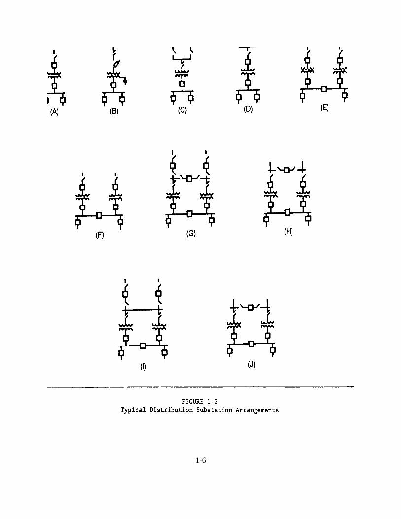
1-6

(b) A transformer section includes one or more transformers with or without automaticload-tap-changing (voltage regulating) capability.
(c) A secondary section provides for the connection of one or more secondary feeders. Each feeder is provided with a switching and interrupting device.
1.4.2.2 Substation Bus Arrangements. A bus is a junction of two or more incoming andoutgoing circuits. The most common bus arrangement consists of one source or supply circuitand one or more feeder circuits. The numerous other arrangements and variations are mainlyintended to improve the service reliability through the bus to all or part of the load duringscheduled maintenance or unexpected power outages. Typical bus arrangements are shown inFigure 1-3.
The arrangements are normally referred to as:
(a) Double-bus.(b) Two-source sectionalizing bus.(c) Three-source sectionalizing bus.(d) Star or synchronizing bus.
When two sources are used simultaneously, but must not be operated in parallel, a normally openbus-tie circuit breaker is interlocked with the source circuit breakers. This permits serving bothbus sections from one of the sources when the other is not available. For normally parallelsources, a single straight bus may be used. It is preferable, however, to use a normally closedbus-tie circuit breaker to split the system so that service continuity can be retained on eithersection when the other section is out of service.
1.4.2.3 Substation Operation. Substations may be attended by operators or designed forautomatic or remote control of the switching and voltage regulating equipment. Most large newsubstations are either automatic or remotely controlled.
(a) In an automatic substation, switching operations are controlled by a separatelyinstalled control system. Major apparatus, such as transformers and converting equipment, maybe placed in or taken out of service automatically. Feeder circuit breakers, after being opened,can be reclosed by protective relays or by the control system.
(b) Remote control substations are often within a suitable distance from attendedstations. In such cases pilot-wire cables provide the communication link to receive indications ofcircuit breaker or switch positions and to transmit control adjustments, as required. Microwaveradio, telephone lines, and carrier current are often used for remote-control links at distancesbeyond the economic reach of pilot wire systems.
1-7

1.4.3 Types of Systems. There are two fundamental types of primary distribution systems;radial and network. Simply defined, a radial system has a single simultaneous path of powerflow to the load. A network has more than one simultaneous path. Each of the two types ofsystems has a number of variations. Figure 1-4 illustrates four primary feeder arrangementsshowing tie, loop, radial and parallel feeders. There are other more complex systems, such as theprimary network (interconnected substations with feeders forming a grid) and dual-servicenetwork (alternate feeder to each load). These systems, however, are simply variations of thetwo basic feeder arrangements.
The following paragraphs discuss the functions and characteristics of the simpler feederarrangements.
1.4.3.1 Tie Feeder. The main function of a tie feeder is to connect two sources. It mayconnect two substation buses in parallel to provide service continuity for the load supplied fromeach bus.
1.4.3.2 Loop Feeder. A loop feeder has its ends connected to a source (usually a singlesource), but its main function is to supply two or more load points in between. Each load pointcan be supplied from either direction; so it is possible to remove any section of the loop fromservice without causing an outage at other load points. The loop can be operated normally closedor normally open. Most loop systems are, however, operated normally open at some point bymeans of a switch. The operation is very similar to that of two radial feeders.
1.4.3.3 Radial Feeder. A radial feeder connects between a source and a load point, and itmay supply one or more additional load points between the two. Each load point can be suppliedfrom one direction only. Radial feeders are most widely used by the Navy because the circuitsare simple, easy to protect, and low in cost.
1.4.3.4 Parallel Feeder. Parallel feeders connect the source and a load or load center andprovide the capability of supplying power to the load through one or any number of the parallelfeeders. Parallel feeders provide for maintenance of feeders (without interrupting service toloads) and quick restoration of service when one of the feeders fails.
1-8

1-9

.1-10

1.5 SECONDARY DISTRIBUTION SYSTEMS. The secondary distribution system is thatportion of the network between the primary feeders and utilization equipment. The secondarysystem consists of step-down transformers and secondary circuits at utilization voltage levels. Residential secondary systems are predominantly single-phase, but commercial and industrialsystems generally use three-phase power.
1.5.1 Secondary Voltage Levels. The voltage levels for a particular secondary system aredetermined by the loads to be served. The utilization voltages are generally in the range of 120 to600 V. Standard nominal system voltages are:
Volts Phase Wire ����� ����� ����
120 Single 2 120/240 Single 3
208Y/120 Three 4
240 Three 3
480Y/277 Three 4 480 Three 3
600 Three 3
In residential and rural areas the nominal supply is a 120/240 V, single-phase, three-wiregrounded system. If three-phase power is required in these areas, the systems are normally208Y/120 V or less commonly 240/120 V. In commercial or industrial areas, where motor loadsare predominant, the common three-phase system voltages are 208Y/120 V and 480Y/277 V. The preferred utilization voltage for industrial plants, however, is 480Y/277 V. Three-phasepower and other 480 V loads are connected directly to the system at 480 V and fluorescentlighting is connected phase to neutral at 277 V. Small dry-type transformers, rated480-208Y/120 or 480-120/240 V, are used to provide 120 V single-phase for convenience outletsand to provide 208 V single- and three-phase for small tools and other machinery.
1.5.2 Types of Systems. Various circuit arrangements are available for secondary powerdistribution. The basic circuits are: simple radial system, expanded radial system, primaryselective system, primary loop system, secondary selective system, and secondary spot network.
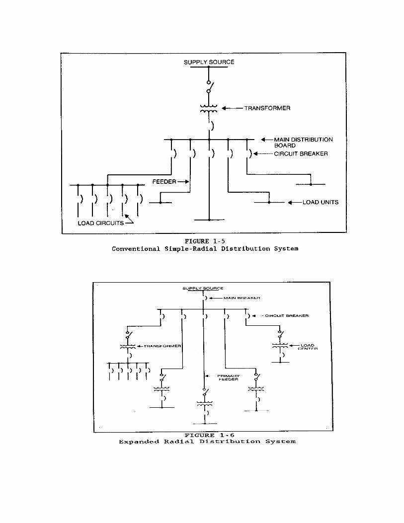
1.5.2.1 Conventional Simple-Radial Distribution System. In the simple-radial system
1-11

(Figure 1-5), distribution is at the utilization voltage. A single primary service and distributiontransformer supply all the feeders. There is no duplication of equipment. System investment isthe lowest of all circuit arrangements. Operation and expansion are simple. Reliability is high ifquality components are used, however, loss of a cable, primary supply, or transformer will cut offservice. Further, electrical service is interrupted when any piece of service equipment must bedeenergized to perform routine maintenance and servicing.
1.5.2.2 Expanded Radial Distribution System. The advantages of the radial system maybe applied to larger loads by using a radial primary distribution system to supply a number of unitsubstations located near the load centers with radial secondary systems (Figure 1-6). Theadvantages and disadvantages are similar to those described for the simple radial system.
1.5.2.3 Primary Selective Distribution System. Protection against loss of a primary supplycan be gained through use of a primary selective system (Figure 1-7). Each unit substation isconnected to two separate primary feeders through switching equipment to provide a normal andan alternate source. When the normal source feeder is out of service for maintenance or a fault,the distribution transformer is switched, either manually or automatically, to the alternate source. An interruption will occur until the load is transferred to the alternate source. Cost is somewhathigher than for a radial system because primary cable and switchgear are duplicated.
1.5.2.4 Loop Primary-Radial Distribution System. The loop primary system (Figure 1-8)offers nearly the same advantages and disadvantages as the primary selective system. The failureof the normal source of a primary cable fault can be isolated and service restored bysectionalizing. Finding a cable fault in the loop, however, may be difficult and dangerous. Thequickest way to find a fault is to sectionalize the loop and reclose, possibly involving severalreclosings at the fault. A section may also be energized at both ends, thus, effecting anotherpotential danger. The cost of the primary loop system may be somewhat less than that of theprimary selective system. The savings may not be justified, however, in view of thedisadvantages.
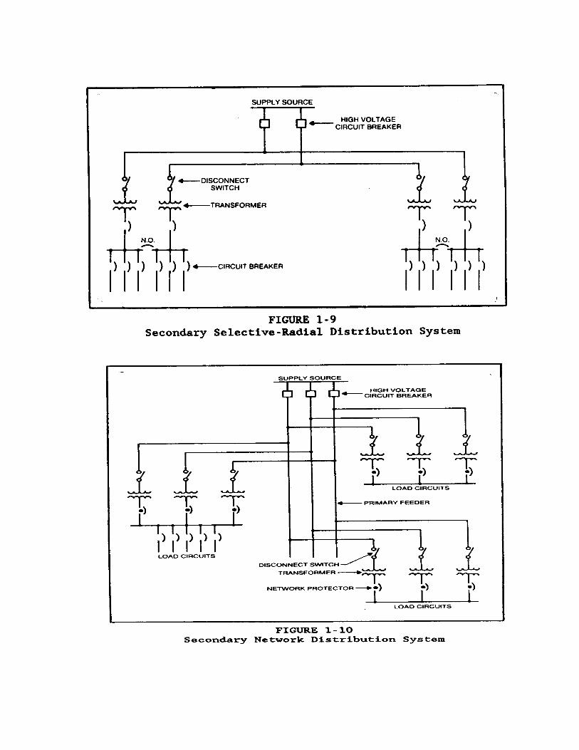
1.5.2.5 Secondary Selective-Radial Distribution System. When a pair of unit substationsare connected through a normally open secondary tie circuit breaker, the result is a secondaryselective-radial distribution system (Figure 1-9). If the primary feeder or a transformer fails, themain secondary circuit breaker on the affected transformer is opened and the tie circuit breaker isclosed. Operation may be manual or automatic. Normally, the stations operate as radial systems. Maintenance of primary feeders, transformer, and main secondary circuit breakers is possiblewith only momentary power interruption, or no interruption, if the stations may be operated inparallel during switching. With the loss of one primary circuit or transformer, the total substationload may be supplied by one transformer. In this situation, however, if load shedding is to beavoided, both transformers and each feeder must be oversized to carry the total load. Adistributed secondary selective system has pairs of unit substations in different locationsconnected by tie cables and normally open tie circuit breakers. The secondary selective systemmay be combined with the primary selective system to provide a high degree of reliability.
1-12

1-14

1.5.2.6 Secondary Network Distribution System. In a secondary network distributionsystem, two or more distribution transformers are each supplied from a separate primarydistribution feeder (Figure 1-10).
The secondaries of the transformers are connected in parallel through a special type of circuitbreaker, called a network protector, to a secondary bus. Radial secondary feeders are tappedfrom the secondary bus to supply loads. A more complex network is a system in which thelow-voltage circuits are interconnected in the form of a grid or mesh.
(a) If a primary feeder fails, or a fault occurs on a primary feeder or distributiontransformer, the other transformers start to feed back through the network protector on the faultedcircuit. This reverse power causes the network protector to open and disconnect the faulty supplycircuit from the secondary bus. The network protector operates so fast that there is minimalexposure of secondary equipment to the associated voltage drop.
(b) The secondary network is the most reliable for large loads. A power interruptioncan only occur when there is a simultaneous failure of all primary feeders or when a fault occurson the secondary bus. There are no momentary interruptions as with transfer switches onprimary selective, secondary selective, or loop systems. Voltage dips which could be caused byfaults on the system, or large transient loads, are materially reduced.
(c) Networks are expensive because of the extra cost of the network protector andexcess transformer capacity. In addition, each transformer connected in parallel increases theavailable short-circuit current and may increase the duty rating requirement of secondaryequipment.
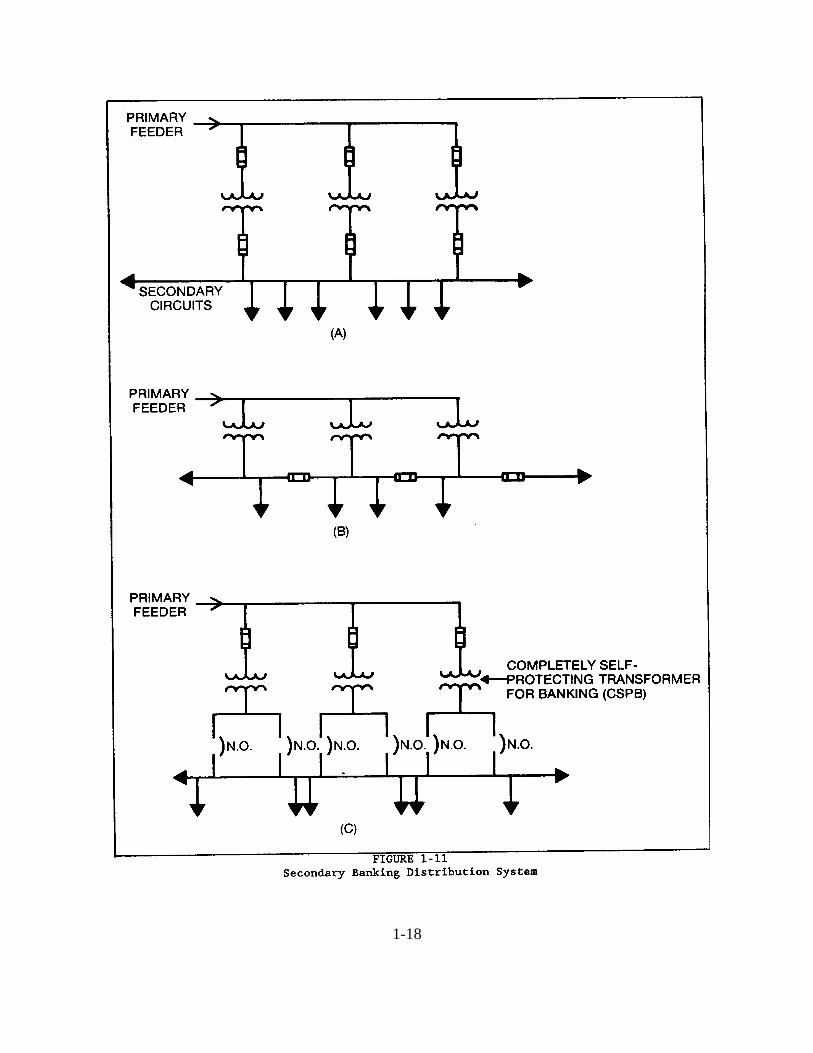
1.5.2.7 Secondary Banking. The term banking means to parallel, on the secondary side, anumber of transformers. All of the transformers are connected to the same primary feeder. Banking is usually applied to the secondaries of single-phase transformers, and the entire bankmust be supplied from the same phase of the primary circuit. All transformers in a bank areusually of the same size and should have the same nominal impedance.
(a) The advantages of banking include: reduction in lamp flicker caused by startingmotors, less transformer capacity required because of greater load diversity, and better averagevoltage along the secondary.
(b) Solid banking, where the secondary conductors are connected without overcurrentprotection, is usually not practiced because of the obvious risks. Three methods of protectingbanked transformers are shown in Figure 1-11. In each arrangement the transformers areconnected to the primary feeder through high-voltage protective links or fuses. Each methodhas different degrees of protection, depending on the location of the protective devices in the
1-15
secondary. Figure 1-11(A) offers the least protection due to the slow acting fuses normally usedin this configuration. In the arrangement of Figure 1-11(B), the secondary circuit issectionalized and the faulted section can be isolated by the fuses.
The third scheme, shown in Figure 1-11(C), utilizes special transformers designed exclusivelyfor banked secondary operation. These transformers, known as completely self-protectingtransformers for banking (CSPB), contain in one integral unit the high-voltage protective linkand the two secondary breakers. When excessive current flows in one of the breakers, it will tripindependently of the other. Fault current protection and sectionalizing of secondary banks aremore efficiently accomplished by this method.
1.6 EMERGENCY AND STANDBY POWER SYSTEMS. The principle and practices ofemergency and standby power systems is presented in this section. Mobile equipment anduninterruptible power supply (UPS) systems are also discussed. Technical information isincluded on typical equipment and systems.
1.6.1 Definitions.
1.6.1.1 Emergency Power System. An emergency power system is an independent reservesource of electric energy. Upon failure or outage of the normal or primary power source, thesystem automatically provides reliable electric power within a specified time. The electric poweris provided to critical devices and equipment whose failure to operate satisfactorily wouldjeopardize the health and safety of personnel or result in damage to property. The emergencypower system is usually intended to operate for a period of several hours to a few days. SeeNAVFAC MO-322 for testing procedures.
1.6.1.2 Standby Power System. An independent reserve source of electric energy which,upon failure or outage of the normal source, provides electric power of acceptable quality andquantity so that the user's facilities may continue satisfactory operation. The standby system isusually intended to operate for periods of a few days to several months, and may augment theprimary power source under mobilization conditions.
1.6.1.3 Uninterruptible Power Supply (UPS). UPS is designed to provide continuouspower and to prevent the occurrence of transients on the power service to loads which cannottolerate interruptions and/or transients due to sensitivity or critical operational requirements.
1.6.2 System Description.
1.6.2.1 Emergency Power Systems. Emergency power systems are of two basic types:
(a) An electric power source separate from the prime source of power, operating inparallel, which maintains power to the critical loads should the prime source fail.
1-17
1-18

(b) An available reliable power source to which critical loads are rapidly switchedautomatically when the prime source of power fails.
Emergency systems are frequently characterized by a continuous or rapid availability of electricpower. This electric power operates for a limited time and is supplied by a separate wiringsystem. The emergency power system may in turn be backed by a standby power system ifinterruptions of longer duration are expected.
1.6.2.2 Standby Power Systems. Standby power systems are made up of the followingmain components:
(a) An alternate reliable source of electric power separate from the prime source.
(b) Starting and regulating controls when on-site standby generation is selected as thesource.
(c) Controls which transfer loads from the prime or emergency power source to thestandby source.
1.6.3 Engine-Driven Generators. These units are work horses which fulfill the need foremergency and standby power. They are available from fractional kW units to units of severalthousand kW. When properly maintained and kept warm, the engine driven generators reliablycome on line within 8 to 15 seconds. In addition to providing emergency power, engine-drivengenerators are also used for handling peak loads and are sometimes used as the preferred sourceof power. They fill the need of backup power for uninterruptible power systems.
1.6.3.1 Generator Voltage. The output of engine-driven generators used for emergency orstandby power service is normally at distribution or utilization voltages. Generators rated at 500kW or less operate at utilization voltages of 480Y/277 V, 208Y/120 V, or 240Y/120 V. Higherrated generators usually operate at nominal distribution system voltages of 2400 V, 4160 V, or13,800 V.
1.6.3.2 Diesel Engine Generators. The ratings of diesel engine generators vary from about2.5 kW to 6500 kW. Typical ratings for emergency or standby power service are 100 kW, 200kW, 500 kW, 750 kW, 1000 kW, 1500 kW, 2000 kW, and 2500 kW. Two typical operatingspeeds of diesel engine generators in emergency and standby service are 1800 rpm and 1200 rpm. Lower speed units are heavier and costlier, but are more suitable for continuous power whilenearly all higher speed (1800 rpm) sets are smaller.
1.6.3.3 Gasoline Engine Generators. Gasoline engines are satisfactory for installations upto approximately 100 kW output. They start rapidly and are low in initial cost as compared todiesel engines. Disadvantages include: higher operating costs, a great hazard due to the storing
1-19
and handling of gasoline, and a generally lower mean time between overhaul.
1.6.3.4 Gas Engine Generators. Natural gas and liquid propane (LP) gas engines rankwith gasoline engines in cost and are available up to about 600 kW. They provide quick startingafter long shutdown periods because of the fresh fuel supply. Engine life is longer with reducedmaintenance because of the clean burning of natural gas.
1.6.3.5 Gas Turbine Generators. Gas combustion turbine generators usually range in sizefrom 100 kW to 20 MW, but may be as large as 100 MW in utility power plants. The gasturbines operate at high speeds (2000 to 5000 rpm) and drive the generators at 900 to 3600 rpmthrough reduction gearing. Gas turbine generator voltages range from 208 V to 22,000 V. Thegas turbine generator system has a higher ratio of kW to weight or to volume than other primemover systems and operates with less vibration than the other internal combustion engines, butwith lower fuel efficiency.
1.6.4 Typical Engine Generator Systems. The basic electrical components are the enginegenerator set and associated meters, controls, and switchgear. Most installations include a singlegenerator set designed to serve either all the normal electrical needs of a building or a limitedemergency circuit. Sometimes the system includes two or more generators of different types andsizes, serving different types of loads. Also, two or more generators may be operating in parallelto serve the same load. Automatic starting of multiple units and automatic synchronizingcontrols are available and practical for multiple-unit installations.
1.6.4.1 Automatic Systems. In order for engine-driven generators to provide automaticemergency power, the system must also include automatic engine starting controls, batteries, anautomatic battery charger, and an automatic transfer device. In most applications, the utilitysource is the normal source and the engine generator set provides emergency power when utilitypower fails. The utility power supply is monitored and engine starting is automatically initiatedonce there is a failure or severe voltage or frequency reduction in the normal supply. Load isautomatically transferred as soon as the standby generator stabilizes at rated voltage and speed. Upon restoration of normal supply, the load is transferred back to the normal source and theengine is shut down.
(a) Automatic transfer devices (ATD) for use with engine-driven generator sets aresimilar to those used with multiple-utility systems, except for the addition of auxiliary contactsthat close when the normal source fails. These auxiliary contacts initiate the starting andstopping of the engine-driven generator. The auxiliary contacts include a paralleling contactor(PC) and a load-dumping contactor (LDC), both electrically operated and mechanically held.
1.6.4.2 Engine Generators (Parallel operation). Figure 1-12 shows a standby powersystem where failure of the normal source would cause both engines to automatically start. Thefirst generator to reach operating voltage and frequency will actuate load dumping control
1-20

circuits and provide power to the remaining load. When the second generator is in synchronism,it will be paralleled automatically with the first. After the generators are paralleled, power isrestored to all or part of the dumped loads. This system is the ultimate in automatic systemsrequiring more complexity and cost than would be appropriate in most activity requirements.
(a) If one generator fails, it is immediately disconnected. A proportionate share of theload is dumped to reduce the remaining load to within the capacity of the remaining generator. When the failed generator is returned to operation, the dumped load is reconnected.
(b) When the normal source is restored, the load is transferred back to it and thegenerators are automatically disconnected and shut down.
1.6.4.3 Peak Load Control System. With the peak load control system shown in Figure1-13, idle standby generator sets can perform a secondary function by helping to supply powerfor peak loads. Depending on the load requirements, this system starts one or more units to feedpeak loads while the utility service feeds the base loads.
1.6.4.4 Combined Utility-Generator Operation. The system shown in Figure 1-14provides switching and control of utility and on-site power. Two on-site buses are provided, (1)supply bus (primary) supplies continuous power for computer or other essential loads, and (2) anemergency bus (secondary) supplies on-site generator power to emergency loads through anautomatic transfer device if the utility service fails.
In normal operation, one of the generators is selected to supply continuous power to the primarybus (EG1 in Figure 1-14). Simplified semiautomatic synchronizing and paralleling controlspermit any of the idle generators to be started and paralleled with the running generator toalternate generators without load interruption. Anticipatory failure circuits permit load transferto a new generator without load interruption. If the generator enters a critical failure mode,however, transfer to a new generator is made automatically with load interruption.
1.6.5 Engine Generator Operation.
1.6.5.1 Governors and Regulation. Governors can operate in two modes, droop andisochronous. With droop operation, the engine's speed is slightly higher at light loads than atheavy loads, while an isochronous governor maintains the same steady speed at any load up tofull load:
speed regulation = (no-load rpm) - (full-load rpm) X 100% ������������������������������� (full-load rpm)
1-21

(a) A typical speed regulation for a governor operating with droop is 3 percent. Thus,if speed and frequency at full load are 1800 rpm and 60 Hz, at no load they would beapproximately 1854 rpm and 61.8 Hz.
A governor would be set for droop only when operating in parallel (in this mode f = 60 Hz +/- 0)with a larger system or in parallel with another generator operating in the isochronous mode. Inthis way, system frequency is maintained and the droop adjustment controls load distributionamong parallel engine generators.
(b) Under steady (or stable) load, frequency tends to vary slightly above and below thenormal frequency setting of the governor. The extent of this variation is a measure of thestability of the governor. An isochronous governor should maintain frequency regulation within+/- 1/4 percent under steady load.
(c) When load is added or removed, speed and frequency dip or rise momentarily,usually for 1 to 3 seconds, before the governor causes the engine to settle at a steady speed at thenew load.
1.6.5.2 Starting Methods. Most engine generator sets use a battery-powered electric motorfor starting the engine. A pneumatic or hydraulic system normally is used only where starting ofthe electric plant is initiated manually.
1.6.6 Turbine-Driven Generators. Steam and petroleum are two general types of turbineprime movers for electrical generators currently available.
1.6.6.1 Steam Turbine Generators. Steam turbines are used to drive generators larger thanthose driven by diesel engines. Steam turbines are designed for continuous operation and usuallyrequire a boiler with a fuel supply and a source of condensing water. Because steam boilersusually have electrically powered auxiliary fans and pumps, steam turbine generators cannot startduring a power outage. Steam turbine generators are, therefore, too large, expensive, andunreliable for use as an emergency or standby power supply. They may also experienceenvironmental problems involving: fuel supply, noise, combustion product output, and heating ofthe condensing water. Steam turbines may also be used in cogeneration systems, where steammay be extracted from the turbine to serve process loads. In this configuration, no steam iscondensed at the turbine exhaust, but rather the turbine operates with a back pressure and servesas a pressure reducing station.
1.6.6.2 Turbine Generators (Petroleum). The most common turbine-driven electricgenerator units employed for emergency or standby power today use gas or oil for fuel. Variousgrades of oil and both natural and propane gas may be used. Other less common sources of fuelare kerosene or gasoline. Gas or oil turbine generators can start and assume load within 40seconds to several minutes for larger units. Gas turbine generators are generally used as
1-23

emergency backup power sources because they start quickly, can assume full load in only one ortwo steps, and are less efficient than other prime movers. When there is a constant need for bothprocess steam (or hot water) and electricity, the gas turbine generator (with an exhaust heatrecovery system) may operate efficiently and continuously in a topping cycle cogenerationconfiguration. Combustion turbine generator sets exhibit excellent frequency control, voltageregulation, transient response, and behavior when operated in parallel with the utility supply.
1.6.7 Mobile Power Systems. One of the most important sources of emergency or standbypower is mobile (transportable) equipment. For most industrial applications, mobile equipmentwill include only two types; diesel-engine-driven and gas-turbine-driven generators.
1.6.7.1 Ratings. Typical ratings of mobile generators range from kW to 2700 kW. Largerpower ratings are satisfied by parallel operation.
1.6.7.2 Accessories. Mobile generators come anywhere from a stripped down unit withnothing but the prime mover and generator to units complete with soundproof chamber, controlpanel, relaying, switchgear, intake and exhaust silencers, fuel tank, battery, and other requiredoperating and safety devices.
1.6.7.3 Navy Mobile Equipment. The Navy's Mobile Utilities Support Equipment(MUSE) program provides specialized, easily transportable utility modules for short-termsupport of shore utility systems. MUSE equipment includes generating units, substations, steamboilers, water treatment plants, and auxiliary equipment. Policy, procedures, and guidance forthe management and use of MUSE are found in NAVFACENGCOM Instruction 11310.2.Detailed technical and general application data for the equipment are provided in the MUSEApplication Guide, NEESA 50.1-001. Copies are available from Commanding Officer, NavalEnergy and Environmental Support Activity, Port Hueneme, CA 93043-5014.
(a) For power plants, the nominal ratings of diesel engine generators are 750 kW to2,500 kW. The gas turbine generators are rated at 750 kW.
(b) The nominal capacities of MUSE substations range from 1,500 kVA to 5,000 kVA. These substations are designed to provide maximum flexibility for transforming various systemvoltages. Presently, transformers rated 3,750 kVA and larger are two winding units, providingtransformation between 13.2 kV or 11.5 kV and 4.16 kV. Either winding may be used as inputor output. Units smaller than 3,750 kVA have three winding transformers. Their High Voltage(HV) winding nominal voltages are 13.2 kV or 11.5 kV; their Intermediate Voltage (IV) windingnominal voltages are 4.16 kV or 2.4 kV; and their Low Voltage (IV) winding nominal voltage is480 V. These units can be operated with the HV or the IV acting as the input or output. The IVwinding is an output winding only.
1-24
1.6.8 Uninterruptible Power Supply Systems. The UPS system includes all mechanical andelectrical devices needed to automatically provide continuous, regulated electric power to criticalloads during primary power system disturbances and outages. During normal conditions, theUPS system receives input power from the primary source and acts as a precise voltage andfrequency regulator to condition output power to sensitive loads. During disturbance or loss ofthe input power, the UPS draws upon its stored-energy source to maintain the regulated outputpower. The stored energy source is usually sized to supply the UPS load for several minutes,until emergency or the normal input power is restored, or until the loads have undergone anorderly shutdown. There are two basic uninterruptible power supply systems: the rotary(mechanical stored-energy) system and the static (solid-state electronic system withstorage-battery).
1.6.8.1 Rotary (Mechanical Stored-Energy) Systems. Upon loss of input power, rotarysystems deliver uninterruptible power by converting the kinetic energy contained in a rotatingmass to electric energy. These systems provide an excellent buffer between the prime powersource and loads that will not tolerate fluctuations in voltage and frequency. Many types ofsystems are in use, but since static equipment has been used to replace rotary systems in the pastten years, only one configuration will be described.
The rotating flywheel no break system is shown in Figure 1-15. An induction motor is drivenfrom the utility supply and this motor is directly coupled to an alternator with its own excitationand voltage regulating system. Coupled directly to the motor generator set is a large flywheelwith one member of a magnetic clutch attached to the flywheel. The other half of the clutch isconnected to a diesel engine or other prime power. Upon loss of alternating current input power,the generator is driven by energy stored in the flywheel until the engine can be started and drivethe generator and flywheel. The voltage regulator maintains the voltage and, with properselection of components to minimize the start and run times of the diesel engine, the frequencydip can be kept to approximately 1.5 to 2 Hz. Thus with a steady-state frequency of 59.5 Hz, theminimum transient frequency would be from 57.5 to 58 Hz. The time for the diesel to start,come up to speed, and assume the load would normally be from 6 to 12 seconds.
1.6.8.2 Static (Solid-State Electronic Circuitry) Systems. The basic static UPS systemconsists of a rectifier, battery, and DC-to-AC inverter. Static systems are very efficient powerconversion devices. The advantages of static systems are stable operation, frequency unaffectedby load changes, excellent voltage regulation, and fast transient response. These systemsnormally operate at 480Y/277 V or 208Y/120 V, 3-phase, 60 Hz input voltage and provide anoutput of 480Y/277 V or 280Y/120 V. Typical output specifications are: voltage regulation of +1percent and frequency regulation of +0.001 percent. The ratings of these systems range from 50VA to more than 1200 kVA. A UPS system can be designed with various combinations ofrectifiers and inverters to operate in a nonredundant or redundant configuration.
(a) A nonredundant UPS system is shown in Figure 1-16. During normal operation,
1-25

the prime power and rectifier supply power to the inverter, and also charge the battery which isfloated on the direct current bus and kept fully charged. The inverter converts power from directto alternating current for use by the critical loads. The inverter governs the characteristics of thealternating current output, and any voltage or frequency fluctuations or transients present on theutility power system are completely isolated from the critical load. When momentary orprolonged loss of power occurs, the battery will supply sufficient power to the inverter tomaintain its output for a specified time until the battery has discharged to a predeterminedminimum voltage. Upon restoration of the prime power, the rectifier section will again resumefeeding power to the inverter and will simultaneously recharge the battery.
(b) The nonredundant UPS system reliability can be improved by installing a staticswitch and bypass parallel with the UPS as shown in Figure 1-17. When an inverter fault issensed, the critical load can be transferred to the bypass circuit in less than 5 milliseconds. Thestatic bypass adds about 20 percent to the cost of a nonredundant system, but is much morereliable.
(c) In the redundant UPS system shown in Figure 1-18, each half of the system has arating equal to the full critical load requirements. The basic power elements (rectifier, inverter,and interrupter) are duplicated, but it is usually not necessary to duplicate the battery since it isextremely reliable. Certain control elements such as the frequency oscillator may also beduplicated. The static interrupters isolate the faulty inverter from the critical bus and prevent theinitial failure from starting a chain reaction which might cause the remaining inverter to fail.The static bypass switch can also be applied to the redundant system.
1-26
1-27
1-28

1-29

CHAPTER 2. POWER DISTRIBUTION CABLE SYSTEMS.
2.1 CABLE SPECIFICATIONS. A cable is defined as a single conductor or an assembly ofconductors covered by solid electrical insulation. Cable specifications generally start with theconductor and progress radially through the insulation and coverings. The following is a typicallist of specifications:
(a) Number of conductors in cable.
(b) Conductor size (American Wire Gage (AWG), circular mil) and material.
(c) Insulation type.
(d) Voltage rating.
(e) Shielding system.
(f) Outer finishes (or sheath).
(g) Installation.
An alternate method of specifying cable is to furnish the ampacity of the circuit (amperes (A)),the voltage (phase to phase, phase to ground, grounded, or ungrounded), and the frequency, alongwith any other pertinent system data.
2.2 CABLE CONSTRUCTION. A typical cable is comprised of conductors shielded by varioustypes of material. The cable may have one conductor or three conductors grouped as one.
2.2.1 Conductors. The two conductor materials in common use are copper and aluminum. Copper has historically been used for conductors of insulated cables primarily for its desirableelectrical and mechanical properties. The use of aluminum is based mainly on its favorableconductivity-to-weight ratio (the highest of the electrical conductor materials), its readyavailability, and the stable low cost of the primary metal.
2.2.1.1 Comparison Between Copper and Aluminum. Aluminum requires largerconductor sizes to carry the same current as copper. The equivalent aluminum cable, whencompared to copper in terms of ampacity, will be lighter in weight and larger in diameter. Fordistribution, aluminum is commonly rated as equivalent to a copper conductor two AWG sizessmaller, which has almost identical resistance.
2-1
2.2.1.2 Classes of Conductors. Conductors are classified as solid or stranded. A solidconductor is a single conductor of solid circular section. A stranded conductor is composed of agroup of small conductors in common contact. A stranded conductor is used where the solidconductor is too large and not flexible enough to be handled readily. Large solid conductors arealso easily damaged by bending. The need for mechanical flexibility usually determines whethera solid or a stranded conductor is used, and the degree of flexibility is a function of the totalnumber of strands. The strands in the stranded conductor are usually arranged in concentriclayers about a central core. The smallest number of wires in a stranded conductor is three. Thenext number of strands are 7, 19, 37, 61, 91, 127, etc. Both copper and aluminum conductorsmay be stranded.
2.2.1.3 Conductor Sizes. Conductor sizes are ordinarily expressed by two differentnumbering methods: the AWG formerly known as the Browne and Sharpe gage, and the circularmil.
(a) The AWG or conductor sizes are numbered from 30 to 1, then continuing with 0,00, 000, and 0000 (or 1/0, 2/0, 3/0, and 4/0 respectively). Number 30 is the smallest size and 4/0the largest in this system. As an example of the actual physical size of the conductors commonlyused in transmission and distribution work, the diameter of a number 8 AWG is 0.1285 inchesand for a 4/0 AWG it is 0.460 inches.
(b) The circular mil is the unit customarily used in designating the cross sectional areaof wires. A circular mil is defined as the area of a circle having a diameter of 1/1000 of an inch. The circular mils of cross section in a wire are obtained by squaring the diameter expressed asthousandths of an inch. For example, a wire with a diameter of 0.102 inches (102 thousandths ofan inch) has a circular mils cross section of 102 X 102 = 10,404. Conductors larger than 4/0AWG are designated in circular mils. These range from 250,000 to 2,000,000 circular mils (250MCM or 250 kcmil to 2,000 MCM or 2,000 kcmil).
2.2.2 Insulations. Insulations can be classified in broad categories as solid, taped orspecial-purpose insulations. Basic insulating materials are either organic or inorganic. Thefollowing is a list of insulations commonly used:
(a) Thermosetting compounds (solid dielectric). (b) Thermoplastic compounds (solid dielectric). (c) Paper-laminated tapes. (d) Varnished cloth-laminated tapes. (e) Mineral inorganic insulation (solid dielectric granular).
Insulations in general use for voltages above 2 kV are listed below. Solid dielectrics of bothplastic and thermosetting types are being more and more commonly used, while thelaminated-type constructions, such as paper-lead cables are declining in popularity.
2-2
(a) Thermosetting Compounds:
o Cross-Linked polyethylene (XLP or XLPE). o Ethylene propylene rubber (EPR). o Styrene butadiene rubber (SBR). o Silicone rubber. o Oil-base rubber. o Chlorosulfonated polyethylene rubber (CPR). o Butyl rubber.
(b) Thermoplastic Compounds:
o Polyethylene (natural). o Polyvinyl chloride (PVC).
(c) Paper-laminated Tapes.
(d) Varnished Cloth-laminated Tapes.
2.2.3 Shielding of Higher Voltage Cable. For operating voltages below 2 kV, nonshieldedconstructions are normally used. Insulation shielding is required for all nonmetallic, sheathed,single-conductor cables operating above 2 kV and all metallic sheathed cables andmulticonductor cables above 5 kV.
2.2.3.1 Procedure. Shielding is the practice of confining the electric field of the cable tothe insulation surrounding the conductor by means of conducting or semiconducting layers,closely fitting or bonded to the inner and outer surfaces of the insulation. In other words, theouter shield confines the electric field to the space between conductor and shield. The inner orstrand stress relief layer is at or near the conductor potential. The outer or insulation shield isdesigned to carry the charging currents and in many cases fault currents.
2.2.3.2 Purpose. Insulation shields have several purposes:
(a) Confine the electric field within the cable.
(b) Equalize voltage stress within the insulation, minimizing surface discharges.
(c) Protect cable from induced potentials.
(d) Limit electromagnetic or electrostatic interference (radio, TV, etc.).
(e) Reduce shock hazard (when properly grounded).
2-3
2.2.4 Cable Outer Finishes. Cable outer finishes or outer coverings are used to protect theunderlying cable components from the environmental and installation conditions associated withintended service. The choice of cable outer finishes for a particular application is based onelectrical, thermal, mechanical, and chemical considerations. Combinations of metallic andnonmetallic finishes are usually required to provide the total protection needed for the installationand operation.
2.2.4.1 Nonmetallic Finishes.
(a) There are outer coverings (extruded jackets) either thermoplastic or vulcanized,which may be extruded directly over insulation or over electrical shielding systems of metalsheaths or tapes, copper braid, or semiconducting layers with copper drain wires or spiraledcopper concentric wires, or over multiconductor constructions. Commonly used materialsinclude: polyvinyl chloride, nitrile butadiene/polyvinyl chloride (NBR/PVC), polyethylene,cross-linked polyethylene, polychloroprene (neoprene), chlorosulfonated polyethylene, andpolyurethane. These materials provide a high degree of moisture, chemical, and weatheringprotection. They are reasonably flexible, provide some degree of electrical isolation, and areof sufficient mechanical strength to protect the insulating and shielding components from normalservice and installation damage.
(b) A commonly used material is braided asbestos fiber. Asbestos braid is used oncables to minimize flame propagation, smoking, and other hazardous or damaging products ofcombustion which may be evolved by some extruded jacketing materials. Special industrialapplications may require synthetic or cotton fibers applied in braid form. All fiber braidsrequire saturants or coating and impregnating materials to provide some degree of moisture andsolvent resistance as well as abrasive and weathering resistance.
2.2.4.2 Metallic Finishes. These materials are widely used when a high degree ofmechanical, chemical, or short-time thermal protection of the underlying cable components maybe required. Commonly used are interlocked galvanized steel, aluminum, or bronze armor;extruded lead or aluminum; strip formed, welded, and corrugated steel and aluminum; andspirally laid round or flat armor wires. The use of any of these materials will reduce flexibilityof the overall cable, but flexibility must be sacrificed to obtain the other benefits.
(a) The unprotected interlocked armor provides a high degree of mechanical protectionwithout significantly sacrificing flexibility. While not entirely impervious to moisture orcorrosive agents, interlocked armor does provide protection from thermal shock by acting as aheat sink for short-time localized exposure. Where corrosion and moisture resistance arerequired, in addition to mechanical protection, an overall jacket of extruded material may beused. Commonly used interlocked armor materials are: galvanized steel, aluminum (for lessweight and general corrosion resistance), and marine bronze and other alloys (for highlycorrosive atmospheres).
2-4

(b) Longitudinally corrugated metal sheaths (corrugations or bellows formedperpendicular to the cable axis) have been used for many years in direct-burial communicationscables, but only recently has this method of cable core protection been applied to control andpower cables. The sheath material may be of copper, aluminum, a corrosion resistant steel orcopper alloy, or a bimetallic composition of materials selected to best meet the intended service.
(c) Lead or lead alloys are used for industrial power cable sheaths for maximum cableprotection in underground manhole and tunnel or underground duct distribution systems subjectto flooding. While not as resistant to crushing loads as interlocked armor, its very high degree ofcorrosion and moisture resistance makes lead attractive in the above applications. Protectionfrom installation damage can be provided by an outer jacket of extruded material.
(d) Extruded aluminum, copper, die-drawn aluminum, or copper sheaths are used in certainapplications for weight reduction and moisture penetration protection. While more crushresistant than lead, aluminum sheaths are subject to electrolytic attack when installedunderground. Under these conditions, aluminum sheathed cable should be protected with anouter extruded jacket.
(e) A high degree of mechanical protection and longitudinal strength can be obtained byusing spirally wrapped or braided round steel armor wire. This type of outer covering isfrequently used in submarine cable and vertical riser cable for support.
2.2.5 Single-conductor and Multiconductor Constructions. Single-conductor cables areusually easier to handle and can be furnished in longer lengths than multiconductor cables. Multiconductor constructions give smaller overall dimensions than an equivalentsingle-conductor cable, providing a space advantage.
2.3 CABLE RATINGS AND SELECTION CRITERIA. Cables come in various sizes. Thesize of a cable depends on the ampacity or voltage rating of the cable. Cables may containvarious conductor sizes, and the electrical characteristics of the cable depends on the conductorsize used.
2.3.1 Electrical and Environmental Specifications. The selection of power cables involvesthe consideration of various electrical and environmental conditions. These conditions includethe quantity and characteristics of the power being distributed and the degree of exposure toadverse mechanical and thermal stresses. The selection of conductor size is based on thefollowing criteria:
2.3.1.1 Voltage rating.
2.3.1.2 Load current criteria (as related to loadings, thermal effects of the load current,mutual heating, losses produced by magnetic induction, and dielectric losses).
2-5
2.3.1.3 Emergency overload criteria.
2.3.1.4 Voltage drop limitations.
2.3.1.5 Fault current criteria.
2.3.2 Voltage Rating. The selection of the cable insulation (voltage) rating is based on: thephase-to-phase voltage of the system in which the cable is to be applied, the general systemcategory (depending on whether the system is grounded or ungrounded), and the time in which aground fault on the system is cleared by protective equipment. It is possible to operate cables onungrounded systems for long periods of time with one phase grounded due to a fault. Thisresults in line-to-line voltage stress across the insulation of the two ungrounded conductors. Such cable, therefore, must have greater insulation thickness than a cable used on a groundedsystem (where it is impossible to impose full line-to-line potential on the other two unfaultedphases for an extended period of time). Consequently, 100 percent voltage rated cables areapplicable to grounded systems provided with protection which will clear ground faults withinone minute. 133 percent rated cables are required on ungrounded systems where the clearing timeof the 100 percent level category cannot be met, and when there is adequate assurance that thefaulted section will be cleared within one hour. 173 percent voltage level insulation is used onsystems where the time required to deenergize a grounded section is indefinite.
2.3.3 Load Current Criteria. The manufacturer's ampacity recommendations should be usedas load current criteria. The following publications contain ampacity tables for power cables.
(a) IEEE S-135-1-1962, Power Cable Ampacities, Copper Conductors.
(b) IEEE S-135-2-1962, Power Cable Ampacities, Aluminum Conductors.
Ampacity tables indicate the minimum size conductor required, however, conservativeengineering practice, future load growth considerations, voltage drop, and short circuitconsiderations may require the use of larger conductors.
2.3.3.1 Skin and Proximity Effects. Careful consideration must be given when groupingcables, as de-ratings resulting from mutual heating may limit capacity. Paralleling two or moresmaller size cables should be considered over installation of conductors (larger than 500 MCM)because the current carrying capacity, per circular mil of the conductor, decreases for alternatingcurrent circuits (due to skin effect and proximity effect). The reduced ratio of surface tocross-sectional area of larger size conductors is a factor in the reduced ability of the larger cableto dissipate heat. Cables larger than 500 MCM are also more difficult to handle duringinstallation. When cables are used in multiple sets, consideration must be given to the phaseplacement of the cable to minimize the effect of reduced ampacity due to unbalanced distributionof current in the cables. Length of multiple sets should be the same.
2-6
2.3.3.2 Ambient Temperature. Cables must be de-rated when in proximity to other loadedcables or heat sources, or when the ambient temperature exceeds the ambient temperature atwhich the ampacity (current carrying capacity) tables are based. The normal ambienttemperature of a cable installation is the temperature of the environment in which the cable isinstalled with no load being carried on the cable.
2.3.3.3 Surrounding Medium. The thermal characteristics of the medium surrounding thecables are of primary importance in determining the current carrying capacity of the cables. Thetype of soil in which the cable or duct bank is buried has a major effect on the current carryingcapacity of the cables. Porous soils, such as gravel and cinder fill, usually result in highertemperatures and lower ampacities than sandy or clay soil. The moisture content of the soil has amajor effect on the current carrying capacity of cables. In dry sections of the country, cables mayhave to be de-rated, or other precautions taken, to compensate for the increase in thermalresistance due to the lack of moisture. On the other hand, in ground which is continuously wet orunder tidewater conditions, cables may carry higher than normal currents.
2.3.4 EmergencyOverload Criteria. Normal loading limits of insulated wire and cable aredetermined based on many years of practical experience. These limits account for a rate ofinsulation deterioration that results in the most economical and useful life of such cable systems. The anticipated rate of deterioration equates to a useful life of approximately 20 to 30 years. Thelife of cable insulation may be halved, and the average thermal failure rate almost doubled foreach 5 to 15�C increase in normal daily load temperature. The normal daily load temperature isthe average conductor temperature over a typical 24 hour period. It reflects both the change inambient temperature and the change in conductor temperature due to daily load fluctuations. Additionally, sustained operation over and above maximum rated operating temperatures orampacities is not an effective or economical practice, because the temperature rise is directlyproportional to the conductor loss, which increases as the square of the current. The intensifiedvoltage drop may also increase the risks to equipment and service continuity. Maximumemergency overload temperatures for various types of insulation have been established and areavailable as a practical guide. Operation at these emergency overload temperatures should notexceed 100 hours per year, and such 100 hour overload periods should not exceed five during thelife of the cable.
2.3.5 Voltage Drop Criteria. The supply conductor, if not of sufficient size, will causeexcessive voltage drop in the circuit, and the drop will be in direct proportion to the circuitlength. Proper starting and running of motors, lighting equipment, and other loads having heavyinrush currents must be considered. It is recommended that the steady state voltage drop indistribution feeders be no more than four percent.
2.3.6 Fault Current Criteria. Under short-circuit conditions the temperature of the conductorrises rapidly then, due to the thermal characteristics of the insulation, sheath, and surroundingmaterials, it cools off slowly after the short-circuit condition is cleared. A transient
2-7
temperature limit for each type of insulation for short-circuit durations not in excess of 10seconds has been established, and many times this criterion is used to determine minimumconductor size. Insulated Power Cable Engineers Association (IPCEA) standards define themaximum conductor temperature limits allowable under worst-case fault conditions.
2.4 TYPES OF CABLE INSTALLATIONS. There are a variety of ways to install powerdistribution cables. Each method ensures distribution of power with a unique degree ofreliability, safety, economy, and quality for any specific set of conditions. These conditionsinclude the electrical characteristics of the power system, the distance and terrain of distribution,and the expected mechanical and environmental conditions.
2.4.1 Open-Wire. Open-wire construction consists of uninsulated conductors on insulatorswhich are mounted on poles or structures. The conductor may be bare or it may have a thincovering for protection from corrosion or abrasion. The attractive features of this method are itslow initial cost and the fact that damage can be detected and repaired quickly. On the other hand,the uninsulated conductors are a safety hazard and are also highly susceptible to mechanicaldamage and electrical outages resulting from short circuits caused by birds or animals. Propervertical clearances over roadways, walkways, and structures are critical. Exposed open-wirecircuits are also more susceptible to the effects of lightning than other circuits, however, theseeffects may be minimized by the use of overhead ground wires and lightning arresters. Inaddition, there is an increased hazard where crane or boom truck use may be involved. In someareas contamination on insulators and conductor corrosion can result in high maintenance costs.
2.4.2 Aerial Cable. Aerial cable consists of fully insulated conductors suspended above theground. This type of installation is used increasingly, generally for replacing open wiring, whereit provides greater safety and reliability and requires less space. Properly protected cables are nota safety hazard and are not easily damaged by casual contact. They do, however, have the samedisadvantage as open-wire construction, requiring proper vertical clearances over roadways,walkways, and structures.
2.4.2.1 Supports. Aerial cables may be either self-supporting or messenger-supported. They may be attached to pole lines or structures. Self-supporting aerial cables have high tensilestrength for this application. Cables may be messenger-supported either by spirally wrapping asteel band around the cables and the messenger or by pulling the cable through rings suspendedfrom the messenger.
2.4.2.2 Distance. Self-supporting cable is suitable for only relatively short distances, withspans in the range of 100-150 feet. Messenger-supported cable can span relatively largedistances, of over 1000 feet, depending on the weight of the cable and the tensile strength of themessenger. For this reason, aerial cable that must span relatively large distances usually consistsof aluminum conductors to reduce the weight of the cable assembly. The supporting messenger
2-8

provides high strength to withstand climatic rigors or mechanical shock. It may also serve as thegrounding conductor of the power circuit.
2.4.3 Above-Ground Conduits. @Rigid steel conduit systems afford the highest degree ofmechanical protection available in above-ground conduit systems. Unfortunately, this is also arelatively high-cost system. For this reason their use is being superseded, where possible, byother types of conduit and wiring systems. Where applicable, rigid aluminum,intermediate-grade steel conduit, thin-wall EMT, intermediate-grade metal conduit, plastic, fiberand asbestos-cement ducts are being used.
2.4.4 Underground Ducts. Underground ducts are used where it is necessary to provide ahigh degree of safety and mechanical protection, or where above-ground conductors would beunattractive.
2.4.4.1 Construction. Underground ducts use rigid steel, plastic, fiber, andasbestos-cement conduits encased in concrete, or precast multi-hole concrete with close fittingjoints. Clay tile is also used to some extent. Where the added mechanical protection of concreteis not required, heavy wall versions of fiber and asbestos-cement and rigid steel and plasticconduits are direct buried.
2.4.4.2 Cables. Cables used in underground conduits must be suitable for use in wet areas,and protected against abrasion during installation.
2.4.5 Direct Burial. Cables may be buried directly in the ground where permitted by codesand only in areas that are rarely disturbed. The cables used must be suitable for this purpose, thatis, resistant to moisture, crushing, soil contaminants, and insect and rodent damage. Whiledirect-buried cable cannot be readily added to or maintained, the current carrying capacity isusually greater than that of cables in ducts. Buried cable must have selected backfill. It must beused only where the chance of disturbance is unlikely. The cable must be suitably protected,however, if used where the chance of disturbance is more likely to occur. Relatively recentadvances in the design and operating characteristics of cable fault location equipment andsubsequent repair methods and material have diminished the maintenance problem.
2.4.6 Underwater (Submarine) Cable. Submarine cable is used only when no other cablesystem can be used. It supplies circuits that must cross expanses of water or swampy terrain.
2.4.6.1 Construction. Submarine cable generally consists of a lead sheathed cable and isusually armored. Insulation material should be XLP or EPR, except when paper insulation isjustified because of its high resistance to, and freedom from, internal discharge or corona. Multiconductor construction should be used, unless limited by physical factors. The leadsheathing usually consists of a copper-bearing lead material, however, other alloys may berequired when special conditions warrant nonstandard sheathing. The most common type of
2-9
armoring material used for submarine cables is the spirally wrapped round galvanized steel wire. In this type of cable, asphalt impregnated jute is usually applied over the lead sheath and the wirearmor is applied over the jute to reduce mechanical damage and electrolytic corrosion. Anadditional covering of the asphalt impregnated jute may be applied over the wire armor. Nonmetallic sheathed cables are sometimes suitable for certain submarine applications. Thecable must be manufactured specifically for submarine service and, generally, has an increasedinsulation thickness. The cable may require wire armor and should have electrical shielding forall voltage ratings above 600 V.
2.4.6.2 Installation. Submarine cable should lie on the floor of the body of water andshould have ample slack so that slight shifting caused by current or turbulence will not placeexcessive strain on the cable. Where the cable crossing is subject to flow or tidal currents,anchors are often used to prevent excessive drifting or shifting of the cable. In addition to layingcables directly on the bottom, burying cable in a trench using the jetwater method should beconsidered. Cables must be buried in waters where marine traffic is present. The depth of burialshould be enough to prevent damage caused by dragging anchors, which may be in excess of 15feet for large ships on sandy bottoms. Warning signs located on shore at the ends of thesubmarine cable should be provided to prohibit anchoring in the immediate vicinity of the cable.
2.4.7 Grounding of Cable Systems. For safety and reliable operation, the shields and metallicsheaths of power cables must be grounded. Without such grounding, shields would operate at apotential considerably above ground. Thus, they would be hazardous to touch, and would incurrapid degradation of the jacket or other material intervening between shield and ground. This iscaused by the capacitive charging current of the cable insulation which is approximately 1milliampere (mA) per foot of conductor length. This current normally flows at a powerfrequency between the conductor and the earth electrode of the cable, normally the shield. Inaddition, the shield or metallic sheath provides the fault return path in the event of insulationfailure, permitting rapid operation of the protection devices.
2.4.7.1 Grounding Conductor. The grounding conductor, and its attachment to the shieldor metallic sheath, normally at a termination or splice, should have an ampacity no lower thanthat of the shield. In the case of a lead sheath, the grounding conductor must be able to carry theavailable fault current over its duration without overheating. Attachment to shield or sheath isfrequently by means of solder, which has a low melting point; thus an adequate area ofattachment is required.
2.4.7.2 Grounding Methods. The cable shield lengths may be grounded at both ends or atonly one end. If grounded at only one end, any possible fault current must traverse the lengthfrom the fault to the grounded end, imposing high current on the usually very thin shieldconductor. Such a current could damage or destroy the shield, and require replacement of theentire cable rather than only the faulted section. With both ends grounded, the fault currentwould divide and flow to both ends, reducing the duty on the shield, with consequently less
2-10

chance of damage. There are modifications of both systems. In one, single-ended groundingmay be attained by insulating the shields at each splice or sectionalizing point, and groundingonly the source end of each section. This limits possible shield damage to only the faultedsection. Multiple grounding, rather than just double-ended grounding, is simply the grounding ofthe cable shield or sheath at all access points, such as manholes or pull boxes. This also limitspossible shield damage to only the faulted section.
2.5 POWER SYSTEM APPLICATIONS. A power system consists of transmission anddistribution systems. The transmission system is typically of higher voltage and is usuallyreferred to as a high side of the system. The distribution system is called a low side of thesystem. The two systems are usually connected by means of a transformer to transform the highvoltage to low voltage.
2.5.1 Transmission System. Three-phase 3-conductor circuits are universally used intransmission systems. Transmission circuits consist of overhead or underground cables, or somecombination of both.
2.5.1.1 Overhead Systems. Overhead circuits consist of aerial cables or open-wireconductors carried on poles or towers. Aluminum conductors have, to a large degree, replacedcopper in overhead installations. Conductor sizes most commonly used vary from No. 2 AWG to556 kcmil aluminum cable steel reinforced (ACSR) or stranded aluminum alloy.
An aluminum cable stranded around a steel core sized to give the required strength is known asACSR. Other cables are aluminum conductor alloy-reinforced (ACAR) and all aluminum-alloyconductor (AAAC).
2.5.1.2 Underground Systems. In older areas, transmission circuits are often 3-conductorlead-covered cables. Cross-linked polyethylene and ethylene-propylene rubber are replacinglead. Ordinarily, a 3-conductor copper cable varying in size from 1/0 AWG to 500 kcmil isinstalled in underground conduits. Aluminum cable is seldom used in underground installationsbecause these cables are larger than copper cables of equal ampacity.
2.5.2 Primary Distribution System. A 3-phase 3-wire system is commonly used in primarydistribution.
2.5.2.1 Overhead Primaries. The conductor sizes most commonly used in overheadprimaries range from No. 4 AWG ACSR to 336.4 kcmil stranded aluminum. Laterals, orbranches, are often No. 4 or No. 2 AWG ACSR, but feeders run to the larger sizes. Aluminum,ACSR, and alloys of aluminum have largely displaced copper from primary circuit construction,although they may be specified on a copper-equivalent basis. Aerial cable is often used forprimary conductors where clearances are too close for open wire or tree trimming is not
2-11

practicable. The cable in some cases comprises three rubber-insulated, neoprene-insulated, orpolyethylene-insulated conductors lashed to a bare messenger which serves as the neutral for3-phase circuits. In other cases, the phase conductors are supported from the messenger byinsulating spacers; this construction is commonly called spacer cable. Single-phase taps, ineither case, are usually one insulated conductor and messenger or an insulated conductor withneutral strands spiralled around it.
2.5.2.2 Underground Systems. The conductor sizes most commonly used in undergroundprimary distribution vary from No. 6 AWG to 500 kcmil copper. Feeders are usually 3- or4-conductor cable, while laterals may be single-conductor because of the requirement fornumerous transformer taps. On some systems, interconnected cable sheaths are used for theneutral conductor; others use a separate bare neutral or fourth conductor in the cable. Strandedaluminum conductors and aluminum sheaths have been used in some cases, but the increasedoutside diameter usually requires excessive duct space. Recent improvements in polyethyleneinsulation have extended the use of aluminum-conductor cable for direct-buried systems whereoverall size is not detrimental.
2-12

CHAPTER 3. POWER SYSTEM ELECTRICAL EQUIPMENT.
3.1 MAJOR APPARATUS. This chapter provides information regarding the requirements for,and the application of, major apparatus used in an electric power distribution system. Moredetailed information on this apparatus is available in trade standards, as well as in manufacturers'publications and NAVFAC MO-200.
3.1.1 System Components. The major system components described in this chapter are:
(a) Transformers. (b) Voltage Regulators. (c) Switches. (d) Power Circuit Breakers. (e) Automatic Circuit Reclosers. (f) Power Capacitors.
3.1.2 Voltage Classes. Power equipment is normally rated according to the nominal systemvoltage. In equipment terminology, the voltage ratings fall into four classes:
(a) Low voltage - 600 V or less. (b) Medium voltage - above 600 V to 72,500 V. (c) High voltage - above 72,500 V to 242,000 V. (d) Extra-high voltage - above 242,000 V to 800,000 V.
The equipment discussed in this chapter will generally be in the low and medium voltage classes.
3.1.3 Codes and Standards. In general, system designs and installation practices are governedby regulations in the National Electric Code (NEC) and the National Electric Safety Code(NESC). The NEC contains regulations governing the installation of electrical conductors andequipment within or on public and private buildings, mobile homes, recreational vehicles, floatdwellings, and other premises such as yards, carnivals, parking lots and industrial substations. The NESC covers standards for safeguarding people from hazards arising from installation,operation and maintenance of electrical conductors and equipment. The provisions contained inthe NEC define minimum requirements only, and are not intended to be used as designspecifications. Minimum standards relating to electrical equipment have been established by theNational Electrical Manufacturers Association (NEMA), the Institute of Electrical andElectronics Engineers (IEEE), and the American National Standards Institute (ANSI).
3-1

3.2 TRANSFORMERS. Transformers are an essential part of any electrical system. They comein various sizes and voltage ratings. Transformers are used for transforming power from onevoltage level to another.
3.2.1 Fundamental Transformer Principles. A transformer consists of a magnetic core builtup of silicon steel laminations with two sets of coils wound around the core. These coils arecalled the primary and secondary windings. This combination may be used to derive a voltagehigher or lower than the voltage immediately available. The supply voltage is applied to theprimary winding, whether it is the higher or lower voltage winding. The other winding, to whichthe load is connected, is termed the secondary winding. Since electromagnetic induction canonly take place when the magnetic flux is continually varying, transformers can only be used inalternating current circuits.
3.2.1.1 Open-Circuit Characteristics. If an alternating electromotive force (emf) is appliedto the terminals of the primary winding of a transformer with the secondary windingopen-circuited (nothing connected between the secondary terminals), a very small current willflow in the primary circuit. The exciting current has a magnetizing current component thatestablishes the mutual magnetic flux that induces an emf in both primary and secondarywindings. Since the primary and secondary windings are wound on the same core, and themagnetizing flux is common to the two windings, the voltage induced in a single turn of eachwinding will be the same, and the induced voltages in the primary and secondary windings aretherefore in direct proportion to the number of turns in those windings. The exciting current alsohas a core loss component that accounts for the power absorbed by the hysteresis andeddy-current losses in the core.
3.2.1.2 Load Characteristics. The application of a load to the secondary side of thetransformer produces a considerable change in the internal phenomena. When the secondarycircuit is closed, a secondary current flows, the value of which is determined by the magnitude ofthe secondary terminal voltage and the impedance of the load circuit. The secondary load currentproduces in the core a load flux that is in phase with the secondary current, however, thesecondary load current is immediately balanced by a primary load current of such a value that theprimary and secondary load ampere-turns are equal. The secondary load flux is similarlycounteracted by a primary load flux which is in phase with the primary load balancing current,and therefore in phase opposition to, and of the same magnitude as, the secondary load flux. Therefore, the core is left in its initial state of magnetization corresponding to the magnetizingcurrent component of the exciting current; this explains why the iron loss is independent of theload. The total current in the primary circuit is the phasor sum of the primary load current andthe no-load exciting current.
Low core loss transformers, made of a new amorphous type alloy, are still in the prototypedevelopment stage for most types of transformers. There are several test programs under waywith utilities in different parts of the country in which selected.groups of these new type
3-2
transformers have been placed in service in a test program to monitor long term performance ofthe units on overhead distribution circuits. Westinghouse has present capacity for 2400 unit/yearin sizes 10 to 75 kVA and for primary voltages of 2.4 to 19.9 kV. Units for the typically largerthree-phase substation applications are not yet readily available, as the transformer manufacturersare limited by the width of the amorphous steel material, as well as the quantity of material that isavailable from the Allied Corporation, which has the patent on this material. There are presentlyat least three manufacturers offering amorphous steel distribution type transformers forcommercial use.
3.2.2 Losses. A transformer has three distinct circuits; electric, magnetic, and dielectric. Each of these circuits incurs losses, which may be subdivided as follows:
(a) Losses in the electric circuit.
o I2�R loss due to load currents. o I2�R loss due to no-load exciting current. o Eddy-current loss in conductors due to leakage fields.
(b) Losses in magnetic circuit.
o Hysteresis loss in core laminations. o Eddy-current loss in core laminations. o Stray eddy-current loss in core clamps, bolts, and other attachments.
(c) Loss in the dielectric circuit. This loss is small for all voltages up to 50 kV, and isconsequently included in the no-load losses.
3.2.2.1 No-Load and Load Losses. The various losses are normally grouped as follows:
(a) No-load losses (commonly called iron losses).
o I2�R loss due to no-load exciting current. o Hysteresis loss in core laminations. o Eddy-current loss in core laminations. o Stray eddy-current loss in core clamps, bolts and other attachments. o Loss in the dielectric circuit.
In practice only the hysteresis and eddy-current losses are of importance in transformers. Theselosses are constant for a given applied voltage and unaffected by the load on the transformers. The dielectric losses are also functions of the primary and secondary voltages, but vary slightlywith the temperature of the windings affected by the load on the transformer. The copper lossdue to the magnetizing current is generally negligible and is independent of the load for a given
3-3

excitation. This magnetizing current loss is very small in well designed and well constructedtransformers, since this current does not usually exceed 5 percent of the full-load current, and inlarger transformers may even be as low as 1 to 2 percent.
(b) Load losses (commonly called copper losses or short-circuit losses).
o I2�R loss due to load currents. o Eddy-current loss in conductors due to leakage fields.
The I2�R losses due to load and exciting currents are inherent in the transformer design. Thelosses are determined by the length of the windings and the frame dimensions. The loss due tothe additional current required to maintain the rated output is usually negligible. Theeddy-current loss is set up by stray magnetic fields. This loss is also inherent in the transformerdesign and is usually calculated as a percentage of the I2�R loss. The I2�R losses are functionsof the transformer core and winding design, and depend upon voltage transformation ratios,winding conductor sizes, and magnetic core dimensions and loss characteristics. The corehysteresis and eddy-current losses are a function of core dimensions, magnetic materials, andlamination thicknesses.
3.2.3 Insulation. Insulation mediums used in power transformers are either liquid or gas. Inboth cases some solid insulation for major separations is used. Solid insulation separates thehigh-voltage winding from the low-voltage winding. Liquid systems include oil, askarel, andhigh-fire-point liquids such as silicone. The gas systems include air, nitrogen, and fluorogases(such as sulfur hexafluoride). The selection of the insulation medium is dictated mainly by theinstallation site and cost.
3.2.3.1 Oil. Low cost, high dielectric strength, and ability to recover after dielectricoverstress make mineral oil the most widely used transformer insulating material. Due to itsflammable property, oil-insulated transformers are normally used for outdoor installations. Indoor installations require vaults and venting or fire suppression systems.
3.2.3.2 Askarel. Askarel is a generic term for a group of nonflammable syntheticchlorinated hydrocarbons used as electrical insulating media. Each manufacturer of askareltransformers applied a special name for this material. For example, Inerteen(R) is the trade namefor the nonexplosive insulating and cooling liquid produced by Westinghouse. Inerteen(R),nearly water white in color, is produced by chlorination of biphenyl (a common chemical). Theresulting polychlorinated biphenyls (PCBs) are relatively insoluble in water but soluble in fat,and are extremely persistent in the environment. While Inerteen(R) is generally regarded asbeing nontoxic but carcinogenic to humans, very high standards of control against pollution mustbe exercised. The combustion of Inerteen(R) and other askarels has been known to createdioxins as a solid residue or dust. In the public sector, there have been several well documentedfires in which askarel filled transformers have become involved in large building fires. In each
3-4
case, a dioxin residue was found which caused additional environmental problems in cleanup andrepair after the fire incident.
Askarel liquids have been classified as toxic to animals and humans by the EnvironmentalProtection Agency (EPA). As of 1 October 1977, the EPA no longer allows the manufacture ofPCB fluids or the sale of askarel-filled transformers. To avoid an uncontrolled discharge to theenvironment, the users of askarel-insulated transformers must monitor and dispose of PCB liquidin accordance with applicable standards. (See ANSI C107.1-1974, Guidelines for Handling andDisposal of Capacitor- and Transformer-Grade Askarels, Containing Polychlorinated Biphenyls;and IEEE Standard 76-1974, Guide for Acceptance and Maintenance of Transformer Askarel inEquipment.)
3.2.3.3 High-Fire-Point Insulating Liquids. In the late 1970s, less-flammable, nontoxic,high-fire-point (greater than 3000C) fluids were introduced to replace askarel as a transformerdielectric (insulating) fluid. These fluids are designated as either polydimethylsiloxane (silicone)or high-molecular-weight hydrocarbons. These liquids will burn, but they do so very slowly andrelease much less heat than flammable mineral oil. They are also nontoxic, unlike askarel. Because of these characteristics, transformers insulated with high-fire-point liquid may beinstalled inside building areas not containing vaults, liquid confinement areas, or fire suppressionsystems. Although it is rarely economical to do so, askarel transformers may be drained, flushed,and refilled with a high-fire-point liquid. The kVA rating of a retro-filled transformer must bedecreased for continuous service. The National Electric Code (NEC) contains installationinformation for less-flammable liquid insulated transformers. The Factory Mutual ResearchCorporation lists high-fire-point qualifying liquids.
3.2.3.4 Air or Gas. The ventilated dry-type transformer has applications in distributionsystems, and may be installed indoors without a vault. The sealed or gas-filled dry-typetransformer has very limited use, due principally to the higher price. Nitrogen and air-insulatedtransformers are generally limited to 15 kV and lower operating voltages.
3.2.3.5 Basic-impulse Insulation Level (BIL). It is characteristic of most insulations thatthe maximum voltage which they can successfully withstand varies inversely with the duration ofthe voltage. Since power systems are subject to various types of overvoltage, some of longand some of short duration, power distribution equipment is usually required to withstand at leasttwo different types of dielectric tests. The first are the so-called low-frequency (60-cycle) tests,usually of one minute duration, that establish the ability of the insulation to withstand moderateovervoltage of relatively long duration. The others are the impulse tests designed to prove thatthe insulation will not break down on voltage surges of high magnitude but short duration, suchas those produced by lightning. The impulse test commonly used consists of the application of avery short duration full-wave voltage surge of a specified crest value to the equipment insulation. The crest value of the wave the insulation can withstand without breakdown is the BIL. Tosimplify the design and application of electrical equipment, a series of Standard BIL's have been
3-5

established. As an example, for a reference insulation class rated at 15 kV, the BIL is 110 kV.
3.2.4 Cooling. Removal of heat caused by losses is necessary to prevent excessive internaltemperature which would shorten the life of the insulation. The transformer life is cut in half bya 10�C rise in temperature. The general classes of cooling are: self-cooled, forced-air orforced-oil-cooled, and water-cooled. The basic types of cooling are referred to by standarddesignations.
3.2.4.1 Oil Immersed Self-Cooled (OA). In this type of transformer the insulating liquidcirculates by natural convection and heat is dissipated over the radiating surface. The OAtransformer is a basic type and serves as a standard for capacity rating.
3.2.4.2 Oil Immersed Self-Cooled/Forced-Air-Cooled (OA/FA). This type of transformeris basically an OA unit with the addition of external fans to increase heat dissipation from theradiators. It is usually possible to obtain between 15 percent - 33 1/3 percent more capacityrelative to the OA rating with the fans running. The OA/FA transformer is applicable insituations that require short-time peak loads to be carried recurrently, without affecting normalexpected transformer life.
3.2.4.3 Oil Immersed Self-Cooled/Forced-Air Cooled/Forced-Oil (OA/FA/FOA). Therating of an OA transformer can be increased by the addition of fans and oil pumps. Automaticcontrols responsive to liquid temperature are normally used to start the fans and pumps in aselected sequence as transformer loading increases. The increase in capacity over the OA ratingis usually obtained in two stages: first stage - 33 1/3 percent and second stage - 66 2/3 percent. Avariation of these triple-rated transformers is the OA/FOA/FOA type.
3.2.4.4 Oil Immersed Forced-Oil Cooled Forced-Air Cooled (FOA). This type oftransformer uses external oil-to-air heat exchangers requiring both air fans and fluid pump for alloperating conditions. FOA transformers cannot, without pumps and fans, carry rated loads.
3.2.4.5 Oil Immersed Water Cooled (OW). The cooling water runs through coils of pipewhich are in contact with the insulating oil of the transformer. The oil flows around the coils ofpipe by natural convection, thereby effecting the heat transfer to the cooling water. This type oftransformer has no self-cooled rating. The OW/A type is water cooled and self cooled.
3.2.4.6 Oil Immersed Forced-Oil Cooled with Forced-Water Cooled (FOW). This type oftransformer is similar to the FOA unit, except that external oil-to-water heat exchangers are used.
3.2.4.7 Dry-Type Transformers. In dry-type transformers, available at voltage ratings of15 kV and below, cooling is accomplished primarily by internal air flow. Three classes ofdry-type transformers are: self-cooled (AA), forced-air cooled (AFA) and self-cooled/forced-aircooled (AA/FA).
3-6
3.2.5 Transformer Impedance. The turns ratio of a-two-winding transformer determines theratio between primary and secondary terminal voltages, when the transformer load current iszero. When load is applied to the transformer, however, the load current encounters an apparentimpedance within the transformer which causes the ratio of terminal voltages to departfrom the actual turns ratio. This internal impedance consists of two components:
(a) A reactance derived from the effect of leakage flux in the windings.
(b) An equivalent resistance which represents all losses traceable to the flow of loadcurrent, such as conductor I2�R loss and stray eddy-current loss.
3.2.5.1 Percent Impedance. Transformer impedance is conveniently expressed in percent,and is determined by the ratio of impedance voltage to rated primary voltage. In three-phasetransformer banks, it is usually appropriate to refer both impedance voltage and rated voltage to aline-to-neutral basis. Percent impedance is also equal to measured ohmic impedance, expressedas a percentage of base ohms. Base ohms for a transformer circuit is defined as the rated current(per phase) divided into rated voltage (line-to-neutral), with the rated current derived from theself-cooled rating of the transformer.
3.2.5.2 Impedance Values. The percent impedance values depend on various factorsincluding the number of windings, particular phase, high and low voltage ratings, transformerkVA rating, and the insulation medium and cooling class. In general, impedance values increasewith higher voltage and kVA ratings. For most purposes, the impedance of power transformersmay be considered equal to their reactances because the resistance component is negligible.
3.2.5.3 Fault Current Stresses. The standard transformer is designed with a limited abilityto withstand the stresses imposed by external short circuits. The maximum short-circuit currentmagnitude and duration that a transformer can endure without incurring thermal and magneticdamage varies with transformer size and the number of phases. ANSI Std. C57.1200defines the fault current withstand capability for liquid-immersed transformers.
3.2.6 Regulation. The full load regulation of a power transformer is the change in secondaryvoltage, expressed in percent of rated secondary voltage, that occurs when the rated kVA outputat a specified power factor is reduced to zero, with the primary voltage maintained constant. Thepercent regulation can be calculated from the measured impedance characteristics at any load andpower factor. The regulation can also be determined by loading the transformer according to therequired conditions at rated voltage and measuring the rise in secondary voltage when the load isdisconnected.
3.2.6.1 Effect of Variables. The percent regulation varies inversely with respect to thepower factor (being lowest at unity power factor) and directly with the impedance. Transformershaving very good regulation (low impedance), however, are also susceptible to higher fault
3-7
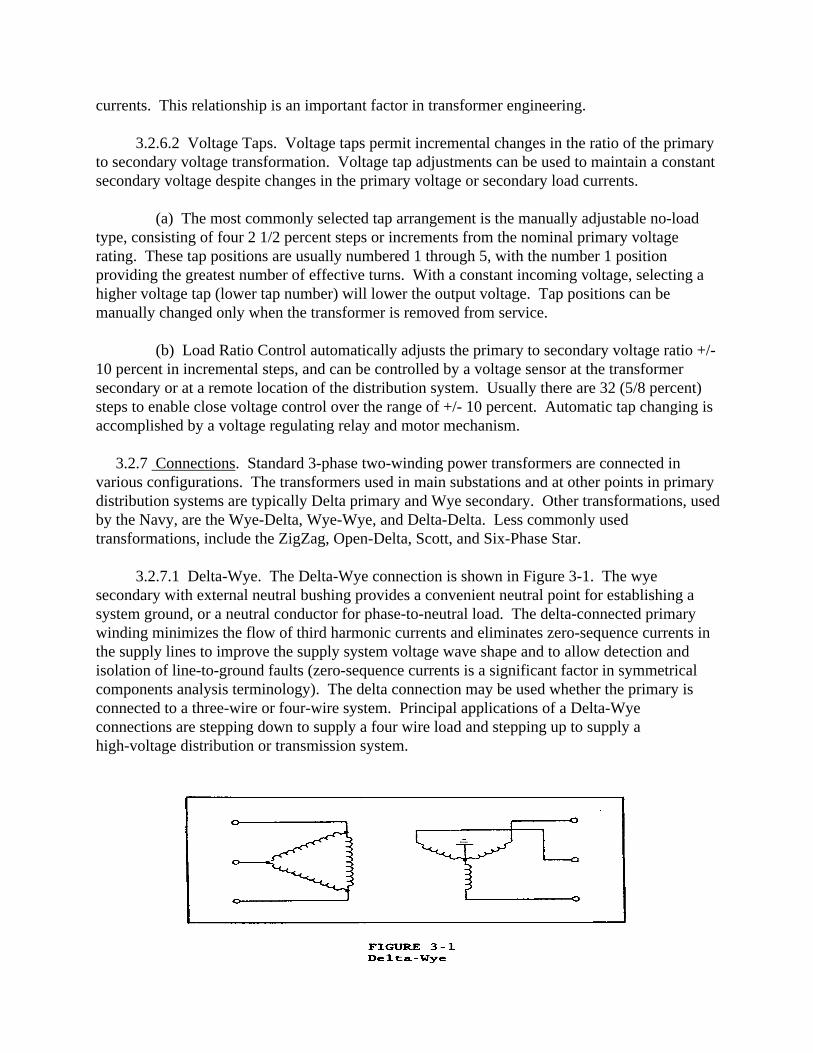
currents. This relationship is an important factor in transformer engineering.
3.2.6.2 Voltage Taps. Voltage taps permit incremental changes in the ratio of the primaryto secondary voltage transformation. Voltage tap adjustments can be used to maintain a constantsecondary voltage despite changes in the primary voltage or secondary load currents.
(a) The most commonly selected tap arrangement is the manually adjustable no-loadtype, consisting of four 2 1/2 percent steps or increments from the nominal primary voltagerating. These tap positions are usually numbered 1 through 5, with the number 1 positionproviding the greatest number of effective turns. With a constant incoming voltage, selecting ahigher voltage tap (lower tap number) will lower the output voltage. Tap positions can bemanually changed only when the transformer is removed from service.
(b) Load Ratio Control automatically adjusts the primary to secondary voltage ratio +/-10 percent in incremental steps, and can be controlled by a voltage sensor at the transformersecondary or at a remote location of the distribution system. Usually there are 32 (5/8 percent)steps to enable close voltage control over the range of +/- 10 percent. Automatic tap changing isaccomplished by a voltage regulating relay and motor mechanism.
3.2.7 Connections. Standard 3-phase two-winding power transformers are connected invarious configurations. The transformers used in main substations and at other points in primarydistribution systems are typically Delta primary and Wye secondary. Other transformations, usedby the Navy, are the Wye-Delta, Wye-Wye, and Delta-Delta. Less commonly usedtransformations, include the ZigZag, Open-Delta, Scott, and Six-Phase Star.
3.2.7.1 Delta-Wye. The Delta-Wye connection is shown in Figure 3-1. The wyesecondary with external neutral bushing provides a convenient neutral point for establishing asystem ground, or a neutral conductor for phase-to-neutral load. The delta-connected primarywinding minimizes the flow of third harmonic currents and eliminates zero-sequence currents inthe supply lines to improve the supply system voltage wave shape and to allow detection andisolation of line-to-ground faults (zero-sequence currents is a significant factor in symmetricalcomponents analysis terminology). The delta connection may be used whether the primary isconnected to a three-wire or four-wire system. Principal applications of a Delta-Wyeconnections are stepping down to supply a four wire load and stepping up to supply ahigh-voltage distribution or transmission system.
3.2.7.2 Wye-Delta. The Wye-Delta connection is shown in Figure 3-2. Wye-Deltaconnections are generally used for large-ratio step-down transformers. The primary is a wyeconnection due to the inherent mechanical and electrical advantages of wye circuits, while a deltaconnected secondary provides an improved waveform to loads.
3.2.7.3 Wye-Wye. The Wye-Wye connection is shown in Figure 3-3. Wye-Wyeconnections are seldom used since they are subject to disturbances from harmonic voltages andcurrents. Unbalanced loads cannot be carried on the secondary unless the primary neutral isprovided. For those applications which require a wye-wye transformation, a third winding, deltaconnected and designated as the tertiary is recommended to provide a low impedance path forzero-sequence currents. The third winding can also be used to serve an auxiliary load if externalconnection facilities are provided.
3.2.7.4 Delta-Delta. The Delta-Delta connection is shown in Figure 3-4. The Delta-Deltaconnection is also seldom used. It is used on Naval ships to enhance damage control. A phase toground fault will be detected but does not trip breakers because there is minimal fault current.
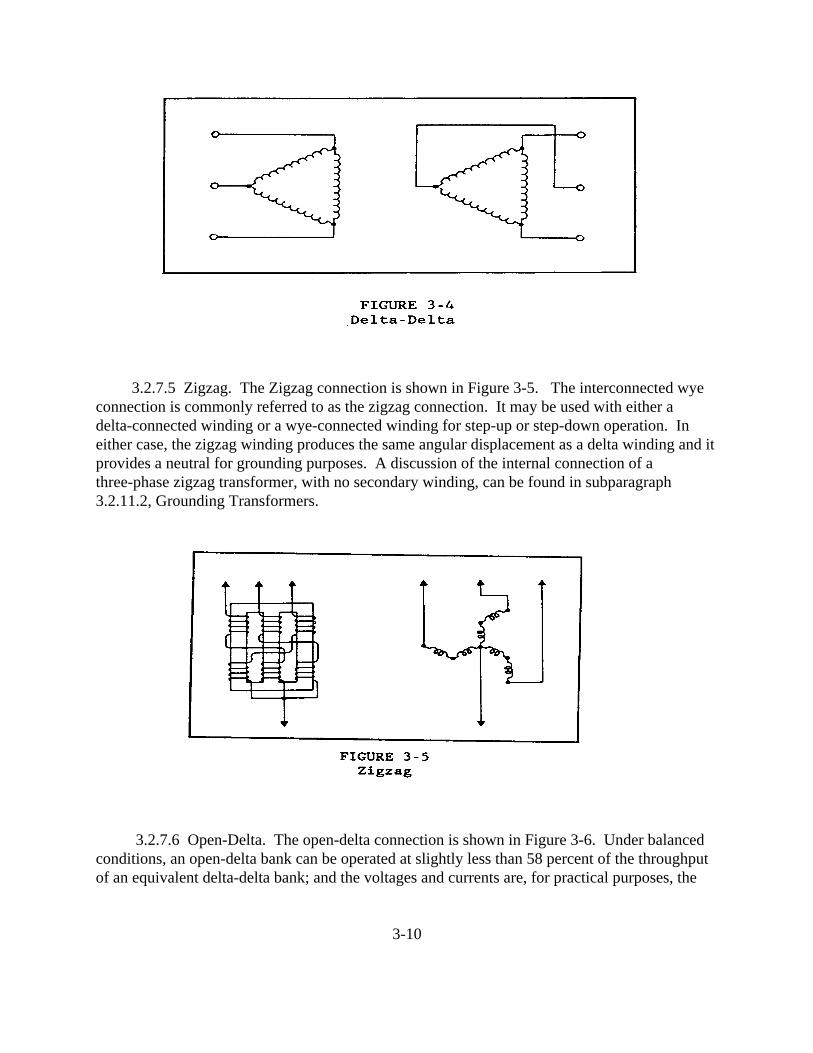
3.2.7.5 Zigzag. The Zigzag connection is shown in Figure 3-5. The interconnected wyeconnection is commonly referred to as the zigzag connection. It may be used with either adelta-connected winding or a wye-connected winding for step-up or step-down operation. Ineither case, the zigzag winding produces the same angular displacement as a delta winding and itprovides a neutral for grounding purposes. A discussion of the internal connection of athree-phase zigzag transformer, with no secondary winding, can be found in subparagraph3.2.11.2, Grounding Transformers.
3.2.7.6 Open-Delta. The open-delta connection is shown in Figure 3-6. Under balancedconditions, an open-delta bank can be operated at slightly less than 58 percent of the throughputof an equivalent delta-delta bank; and the voltages and currents are, for practical purposes, the
3-10
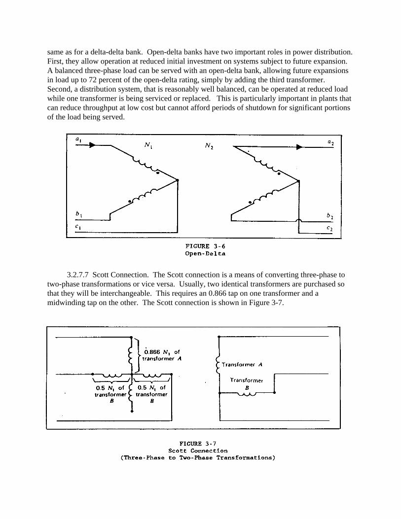
same as for a delta-delta bank. Open-delta banks have two important roles in power distribution. First, they allow operation at reduced initial investment on systems subject to future expansion. A balanced three-phase load can be served with an open-delta bank, allowing future expansionsin load up to 72 percent of the open-delta rating, simply by adding the third transformer. Second, a distribution system, that is reasonably well balanced, can be operated at reduced loadwhile one transformer is being serviced or replaced. This is particularly important in plants thatcan reduce throughput at low cost but cannot afford periods of shutdown for significant portionsof the load being served.
3.2.7.7 Scott Connection. The Scott connection is a means of converting three-phase totwo-phase transformations or vice versa. Usually, two identical transformers are purchased sothat they will be interchangeable. This requires an 0.866 tap on one transformer and amidwinding tap on the other. The Scott connection is shown in Figure 3-7.

3.2.7.8 Six-Phase Star. The six-phase star connection is shown in Figure 3-8. It providesa means for converting three-phase to six-phase transformations and is used in many rectifier andthyristor circuits where a path for DC current flow is required. The characteristic angle of asix-phase system is 60 degrees.
3.2.8 Loading of Transformers. Ordinarily the kVA that a transformer should carry is limitedby the effect of reactance on regulation or by the effect of load losses on system economy. Attimes it is desirable to ignore these factors and increase the kVA load until the effect oftemperature on insulation life is the limiting factor. High temperature decreases the mechanicalstrength and increases the brittleness of fibrous insulation, making transformer failureincreasingly likely, even though the dielectric strength of the insulation material may not beseriously degraded. Overloading of transformers should be limited by reasonable considerationof the effect on insulation and, consequently, transformer life.
3.2.8.1 Kilovolt-Amperes (kVA) Ratings. Ratings in kVA or megavolt-amperes (MVA)will include the self-cooled rating at a specified temperature rise, as well as the forced-cooledratings if the transformer is so equipped. As a minimum consideration, the self-cooled ratingshould be at least equal to the expected peak demand.
3.2.8.2 Winding Temperature. The standard allowable average winding, of copper,temperature rise (by resistance test) for the modern liquid-filled power transformer is either55�C/65�C or 65�C, based on an average ambient of 30�C (40�C maximum) for any 24 hour
3-12

period. Since temperature distribution is uneven in most transformers, hottest-spotinsulation temperature usually determines insulation life and, therefore, transformer loading. A65�C rated transformer in a 30�C ambient environment is usually rated for a hottest spottemperature of 110�C.
3.2.8.3 Overloads. Transformers have certain overload capabilities, varying with ambienttemperature, pre-loading, and overload duration. These capabilities are defined in ANSI Std. C57.92, Guide for Loading Mineral-Oil-Immersed Distribution and Power Transformers, andANSI Std. C57.96, Guide for Loading Dry-Type Distribution and Power Transformers.
3.2.9 Parallel Operation. The theoretically ideal conditions for paralleling transformers are:
(a) Identical turns ratios and voltage ratings. (b) Equal percent impedances. (c) Equal ratios of resistance to reactance. (d) Same polarity. (e) Same phase angle shift. (f) Same phase rotation.
3.2.9.1 Single-Phase Transformers. Only the first four conditions for parallelingtransformers (listed above) apply to single-phase transformers, as there is no voltagetransformation related to phase angle shift or phase rotation. All six conditions apply, however,to paralleling three-phase-banks of single-phase transformers. If the turns ratios are not the same,a circulating current will flow even at no load. If the percent impedance or the ratios ofresistance to reactance are different, there will be no circulating current at no load, and thedivision of load between the loaded transformers will no longer be proportional to their kVAratings.
3.2.9.2 Three-Phase Transformers. While the same transformer paralleling conditionsapply to three-phase transformers, consideration must be given to the phase angle shift and tophase rotation. The transformers must have the same winding arrangement.
(a) Certain transformer connections as the Wye-Delta or Wye-Zigzag produce a 30�
shift between the line voltages on the primary side and those on the secondary side. Transformers with these connections cannot be paralleled with transformers not having this shiftsuch as Wye-Wye, Delta-Delta, Zigzag-Delta, or Zigzag-Zigzag.
(b) Phase rotation refers to the sequence in which the terminal voltages reach theirmaximum values. In paralleling, those terminals whose voltage maximums occur simultaneouslyare paired.
3.2.9.3 Power Transformer Practice. The preceding discussion covered the theoretically
3-13
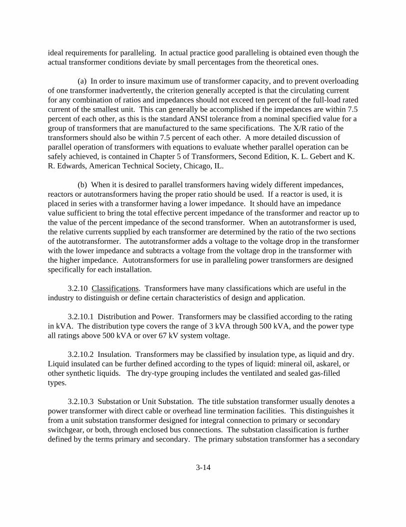
ideal requirements for paralleling. In actual practice good paralleling is obtained even though theactual transformer conditions deviate by small percentages from the theoretical ones.
(a) In order to insure maximum use of transformer capacity, and to prevent overloadingof one transformer inadvertently, the criterion generally accepted is that the circulating currentfor any combination of ratios and impedances should not exceed ten percent of the full-load ratedcurrent of the smallest unit. This can generally be accomplished if the impedances are within 7.5percent of each other, as this is the standard ANSI tolerance from a nominal specified value for agroup of transformers that are manufactured to the same specifications. The X/R ratio of thetransformers should also be within 7.5 percent of each other. A more detailed discussion ofparallel operation of transformers with equations to evaluate whether parallel operation can besafely achieved, is contained in Chapter 5 of Transformers, Second Edition, K. L. Gebert and K.R. Edwards, American Technical Society, Chicago, IL.
(b) When it is desired to parallel transformers having widely different impedances,reactors or autotransformers having the proper ratio should be used. If a reactor is used, it isplaced in series with a transformer having a lower impedance. It should have an impedancevalue sufficient to bring the total effective percent impedance of the transformer and reactor up tothe value of the percent impedance of the second transformer. When an autotransformer is used,the relative currents supplied by each transformer are determined by the ratio of the two sectionsof the autotransformer. The autotransformer adds a voltage to the voltage drop in the transformerwith the lower impedance and subtracts a voltage from the voltage drop in the transformer withthe higher impedance. Autotransformers for use in paralleling power transformers are designedspecifically for each installation.
3.2.10 Classifications. Transformers have many classifications which are useful in theindustry to distinguish or define certain characteristics of design and application.
3.2.10.1 Distribution and Power. Transformers may be classified according to the ratingin kVA. The distribution type covers the range of 3 kVA through 500 kVA, and the power typeall ratings above 500 kVA or over 67 kV system voltage.
3.2.10.2 Insulation. Transformers may be classified by insulation type, as liquid and dry. Liquid insulated can be further defined according to the types of liquid: mineral oil, askarel, orother synthetic liquids. The dry-type grouping includes the ventilated and sealed gas-filledtypes.
3.2.10.3 Substation or Unit Substation. The title substation transformer usually denotes apower transformer with direct cable or overhead line termination facilities. This distinguishes itfrom a unit substation transformer designed for integral connection to primary or secondaryswitchgear, or both, through enclosed bus connections. The substation classification is furtherdefined by the terms primary and secondary. The primary substation transformer has a secondary
3-14
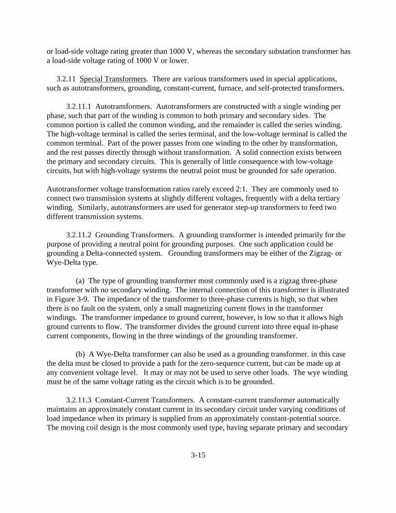
or load-side voltage rating greater than 1000 V, whereas the secondary substation transformer hasa load-side voltage rating of 1000 V or lower.
3.2.11 Special Transformers. There are various transformers used in special applications,such as autotransformers, grounding, constant-current, furnace, and self-protected transformers.
3.2.11.1 Autotransformers. Autotransformers are constructed with a single winding perphase, such that part of the winding is common to both primary and secondary sides. Thecommon portion is called the common winding, and the remainder is called the series winding. The high-voltage terminal is called the series terminal, and the low-voltage terminal is called thecommon terminal. Part of the power passes from one winding to the other by transformation,and the rest passes directly through without transformation. A solid connection exists betweenthe primary and secondary circuits. This is generally of little consequence with low-voltagecircuits, but with high-voltage systems the neutral point must be grounded for safe operation.
Autotransformer voltage transformation ratios rarely exceed 2:1. They are commonly used toconnect two transmission systems at slightly different voltages, frequently with a delta tertiarywinding. Similarly, autotransformers are used for generator step-up transformers to feed twodifferent transmission systems.
3.2.11.2 Grounding Transformers. A grounding transformer is intended primarily for thepurpose of providing a neutral point for grounding purposes. One such application could begrounding a Delta-connected system. Grounding transformers may be either of the Zigzag- orWye-Delta type.
(a) The type of grounding transformer most commonly used is a zigzag three-phasetransformer with no secondary winding. The internal connection of this transformer is illustratedin Figure 3-9. The impedance of the transformer to three-phase currents is high, so that whenthere is no fault on the system, only a small magnetizing current flows in the transformerwindings. The transformer impedance to ground current, however, is low so that it allows highground currents to flow. The transformer divides the ground current into three equal in-phasecurrent components, flowing in the three windings of the grounding transformer.
(b) A Wye-Delta transformer can also be used as a grounding transformer. in this casethe delta must be closed to provide a path for the zero-sequence current, but can be made up atany convenient voltage level. It may or may not be used to serve other loads. The wye windingmust be of the same voltage rating as the circuit which is to be grounded.
3.2.11.3 Constant-Current Transformers. A constant-current transformer automaticallymaintains an approximately constant current in its secondary circuit under varying conditions ofload impedance when its primary is supplied from an approximately constant-potential source. The moving coil design is the most commonly used type, having separate primary and secondary
3-15

3-16

coils which are free to move with respect to each other, thereby varying the magnetic leakagereactance of the transformer. This reactance automatically adjusts itself to a value which, whenadded to the load impedance, permits a constant current to flow. Constant-current transformersare used primarily for series street lighting circuits. Standard output ratings are 10, 15, 20, 25and 30 kW. The standard rated output current of these transformers is 6.6 or 20 A.
3.2.11.4 Furnace Transformers. Furnace transformers supply power to various types ofelectric furnaces. The secondary voltages are low, generally several hundred volts, andoccasionally less than 100 V. Sizes range from a few kVA to over 50 MVA, with secondarycurrents over 60,000 A. High currents are obtained by parallel connection of many windingsections and collected by internal bus bars.
3.2.11.5 Self-Protected Transformers. Self-protected transformers generally have aninternally mounted, thermally controlled secondary breaker for overload and short-circuitprotection; an internally mounted protection link in series with the high-voltage winding todisconnect the transformer from the line in the event of an internal coil failure; and a lightningarrester, or arresters, integrally mounted on the outside of the tank for overvoltage protection.
3.3 VOLTAGE REGULATORS. The function of a transmission and distribution system is todeliver power to the user at a voltage that is within acceptable limits. It is impractical, however,to regulate large systems solely by means of generator regulators. Other devices for correctingthe voltage, therefore, are commonly used throughout the system. These devices includetransformers with automatic load-tap-changers, synchronous condensers, switched capacitors,and voltage regulators.
3.3.1 Definition. A voltage regulator (transformer type) is an induction device havingwindings in shunt with the primary circuit and secondary windings in series with the regulatedcircuit. Although similar in operation to transformer load-tap-changing equipment, voltageregulators are distinct pieces of power system apparatus.
3.3.2 Types of Voltage Regulators. There are three types of regulators; step, induction, andferroresonant. The induction regulator was commonly used in the past for power circuits,however, it has been generally replaced by the less expensive and more serviceable stepregulator. The ferroresonant transformer (FRT) has been used as a constant voltagetransformer in low power applications (less than 1 kVA to approximately 15 kVA) for manyyears. With proper filtering, the FRT is now used quite often to serve sensitive electronic andcomputer equipment.
3.3.2.1 Step Voltage Regulator. The step voltage regulator is an autotransformer equippedwith a mechanism capable of changing taps under load. Standard step regulators have aregulation range of +/- 10 percent of the applied voltage. This range is usually divided into
3-17
thirty-two 5/8 percent steps so that each change represents a specific increment of voltage.
3.3.2.2 Induction Voltage Regulator. Induction voltage regulators operate on thetransformer principle although their construction resembles that of a wound-rotor inductionmotor. The shunt winding is connected across the line and supplies excitation for the regulator. Upon excitation of the shunt winding, a voltage is induced in the series winding. Although itremains constant in magnitude, the phase relationship of the induced voltage, with respect to thevoltage of the shunt winding, changes as the rotor is turned. The position of the rotor, therefore,determines how much buck or boost voltage is imparted by the regulator at any given time.
3.3.2.3 Ferroresonant Constant Voltage Transformer. The ferroresonant constant voltagetransformer was patented in 1938. Generally, it consists of a resonant electrical circuit and a highleakage reactance magnetic circuit. The output voltage remains essentially constant for a widerange (+/- 15 percent) of input voltage. The principle of operation is a resonant circuit,consisting of a series coil and a capacitor, tuned to resonate at approximately 60 Hz. A saturableinductor is the secondary winding of the transformer and operates in saturation in the designinput voltage range of the unit to deliver a constant output voltage. The output voltage is rich inharmonics (usually 20 percent or more harmonic distortion). For use with loads sensitive tothese harmonics, extra filtering coils must be added to the output circuitry to reduce harmonicdistortion to less than 3 percent. The FRT's are available in designs up to approximately 15 kVAand are usually used on low voltage (120 to 240 V) circuits. Higher power and voltage ratingsare limited by the capacitor sizing and other methods of regulation are more economic at thehigher voltage and power levels. These types of units are frequency sensitive. The unitsdesigned to operate at 60 Hz are not suitable for use at 50 Hz, which is the power sourceavailable in many foreign countries.
3.3.3 Ratings. Voltage regulators are rated in terms of the number of phases, capacity inkVA, primary voltage, percent regulation, and frequency. In addition, information concerningtemperature rise, impedance, insulation level, type of cooling, method of making connections,and similar data is given on the nameplate.
3.3.3.1 kVA Rating. The kVA rating of a regulator is the product of the load amperes andthe voltage of the series winding in kilovolts. Standard ratings of regulators are available up to833 kVA single-phase and 2500 kVA three-phase for line voltages of 2500 V to 34,500 V. Toenable regulation of 25,000 kVA circuits, 10 percent regulation units have a kVA regulatedcircuit reading ten times higher than that of the regulator kVA.
3.3.3.2 Insulation and Cooling. Standard regulators are oil-immersed and self-cooled. Units above 500 kVA can usually accommodate fans for forced cooling, adding up to 66 percentto the self-cooled rating.
3.3.4 Applications. Voltage regulators are installed on distribution systems to keep voltages
3-18
at a selected value. The location of a regulator is determined by the type of loads and circuitsserved. Regulators are available for ground or pole installation.
3.3.4.1 Bus Regulators. Bus regulation is often used when a substation has two or morecircuits with similar load characteristics and requirements. For such applications the regulatorinstallation controls the voltage on the substation bus rather than on individual circuits. Voltageregulation of the bus can also be accomplished by equipping the station's power transformer witha load tap changing (LTC) mechanism.
3.3.4.2 Feeder Regulators. Feeder regulators maintain a constant voltage on a particularcircuit with variation in load. They may be installed at a substation or located between thesubstation and the load being served. On long lines, or lines with critical loads, two or moreregulator installations may be warranted in order to cope with the circuit requirements. Thesemay be located either on the main feeder or branch feeder circuits.
3.3.5 Regulator Control. Most modern regulators are motor-operated and automaticallycontrolled. Facilities are provided for the regulator to control the voltage at a point remote fromthe regulator location. The components required to automatically control a motor-operatedregulator are:
(a) Voltage sensing device. (b) Amplifying section. (c) Motor drive. (d) Line-drop compensator.
A voltage sensing device is connected through a potential transformer across the feeder or bus tobe regulated. The voltage sensing device, which may be either a voltage-regulating relay or astatic voltage sensor, operates a switch that controls the operating motor of the regulator. Acurrent transformer connected in series with the regulated circuit has its secondary windingnormally connected to a line-drop compensator. This line-drop compensator contains variableresistance and reactance (each independently adjustable) which represents the impedance of aregulated circuit. The voltage drop in the regulated circuit is, thus, easily detected by aproportional voltage drop across the compensator. Once adjusted, the compensator permits theregulator to hold constant voltage at a selected point on the circuit, regardless of load or powerfactor.
3.3.6 Single- and Three-Phase Connections. Single-phase regulators are applied to controlthe voltage on a single-phase circuit. They may, however, be applied to three-phase circuits andhave some advantage over three-phase units that regulate all three phases in the same manner. Single-phase units, when applied to three-phase circuits, can be adjusted for separate regulationlevels. A three-phase unit can only be adjusted for an average value of the three phase
3-19
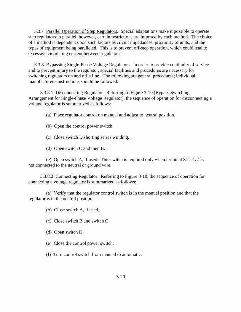
3.3.7 Parallel Operation of Step Regulators. Special adaptations make it possible to operatestep regulators in parallel, however, certain restrictions are imposed by each method. The choiceof a method is dependent upon such factors as circuit impedances, proximity of units, and thetypes of equipment being paralleled. This is to prevent off-step operation, which could lead toexcessive circulating current between regulators.
3.3.8 Bypassing Single-Phase Voltage Regulators. In order to provide continuity of serviceand to prevent injury to the regulator, special facilities and procedures are necessary forswitching regulators on and off a line. The following are general procedures; individualmanufacturer's instructions should be followed.
3.3.8.1 Disconnecting Regulator. Referring to Figure 3-10 (Bypass SwitchingArrangement for Single-Phase Voltage Regulator), the sequence of operation for disconnecting avoltage regulator is summarized as follows:
(a) Place regulator control on manual and adjust to neutral position.
(b) Open the control power switch.
(c) Close switch D shorting series winding.
(d) Open switch C and then B.
(e) Open switch A, if used. This switch is required only when terminal S�2� - L�2� isnot connected to the neutral or ground wire.
3.3.8.2 Connecting Regulator. Referring to Figure 3-10, the sequence of operation forconnecting a voltage regulator is summarized as follows:
(a) Verify that the regulator control switch is in the manual position and that theregulator is in the neutral position.
(b) Close switch A, if used.
(c) Close switch B and switch C.
(d) Open switch D.
(e) Close the control power switch.
(f) Turn control switch from manual to automatic.
3-20

3.3.8.3 Regulator Bypassing Equipment. Equipment used to bypass regulators includescircuit breakers, interlocking switches, and cutouts with disconnecting blades. A convenientswitching device is the regulator bypass switch, which includes switches B, C, and D of Figure3-10, as an integral unit. When the regulator bypass switch is operated, the correct switchingsequence occurs.
3-21
3.3.9 Bypassing Three-Phase Voltage Regulators. With the exception of the single-core,3-phase induction regulator, the switching sequence of subparagraph 3.3.8 applies to each phaseof a 3-phase regulator. In such cases, three identical sets of switches would be used. Since thesingle-core, 3-phase induction regulator has no neutral position within the regulation range wherethe series winding voltage is zero, special facilities must be provided.
3.3.10 Regulator Protection.
3.3.10.1 Surge Protection. As previously stated, regulators are constructed very much likeautotransformers, having primary (shunt) and secondary (series) windings. Surge protectionrequirements for regulators are consequently very similar to those for transformers.
3.3.10.2 Short-Circuit Protection. Because voltage regulators are connected in series inthe circuit, they may be subjected to exceptionally severe short-circuit currents. For this reason,current-limiting devices are often installed in the circuit to limit possible fault currents to a valuethat the regulator can withstand.
3.3.10.3 Thermal Protection. There is no inherent thermal protective device built into aregulator. Consequently, the operator must be watchful for overloads that may damage theregulator. Like transformers, regulators have some overload ability and may be overloaded undercertain conditions.
3.4 SWITCHES. A switch is a device for making, breaking, or changing the connections in anelectric circuit. Switches are normally divided into three classes relative to the operatingmedium; air, oil, and vacuum switches.
3.4.1 General Purpose. Air switches are an essential element of electrical power transmissionand distribution systems. They provide positive, visible air-gap isolation for equipment, bus andline sections and facilitate examination, maintenance, and repair. Oil and vacuum switches areprimarily used in underground distribution systems, especially where submersible switchingequipment is required. In addition, oil switches are often used on capacitor circuits.
3.4.2 Ratings. Switches are rated in terms of one or more of the following characteristics;voltage, Basic-impulse Insulation Level (BIL), continuous current, short-time current, andinterrupting current.
3.4.2.1 Voltage Rating. The voltage rating is a value assigned for the purpose ofdesignating dielectric characteristics and should not be exceeded under normal operatingconditions.
3.4.2.2 Basic-impulse Insulation Level. This is the reference insulation level expressed as
3-22

the impulse crest value of withstand voltage of a specified full impulse wave (see subparagraph3.2.3.5).
3.4.2.3 Continuous Current Rating. The continuous current rating is the designated limitof current in amperes that the switch will carry continuously without exceeding a maximumtemperature rise of 30� above ambient. For switches having copper-to-copper contacts or theequivalent, this ambient may be 40�. For switches having all contacts silver-surfaced or theequivalent, this ambient may be 55�C. The limited heat storage capacity of a switch precludesany overload rating. Switches, therefore, should not be operated in excess of their continuouscurrent rating, except under emergency conditions.
3.4.2.4 Interrupting Rating. The interrupting rating indicates the maximum short-circuitcurrent that a switch can interrupt without sustaining damage. No switch should ever be operated(open or close) on an energized power system unless it has sufficient interrupting capacity. Forpersonnel safety, this precaution cannot be overemphasized.
3.4.2.5 Short-Time Rating. All switches have a short-time current rating corresponding tothe switch's ability to carry short-circuit current in the closed position. This rating incorporatesthe limitations imposed by both thermal and electromagnetic effects. The short-time currentrating of a switch is the highest current that the switch is designed to carry without damage forspecified short-time intervals. The short-time current rating consists of two values:
(a) That which the switch can carry for one cycle, referred to as its momentary rating.
(b) That which it can carry for four seconds.
Numerically, the momentary rating is 1.6 times the four-second rating.
3.4.3 Types of Switches and Their Application. There are a variety of switches used in thetransmission and distribution of electric power. The switches are designed for specific purposesand operational conditions. In general, the switches are distinguished by the current handlingcapability; i.e., continuous, loadbreak or non-loadbreak, and fault current.
3.4.3.1 Air Switches.
(a) A disconnect switch is one used for; closing, opening, or changing the connectionsin a circuit or system, or for isolating purposes. It has no interrupting rating and is intended tobe operated only after the circuit has been deenergized by some other means. Disconnectswitches may be either hook- or gang-operated. A series-connected circuit breaker or circuitrecloser should be open on all three phases before a disconnect switch is opened or closed.
(b) Air-break switches are normally mounted on top of their supporting structure and
3-23

are gang-operated. They are either manually operated by means of an operating handle orelectrically operated by means of a motor-operated mechanism. They are used to performvarious switching assignments such as isolating transformers, bypassing circuit breakers, andfor line sectionalizing (where small amounts of magnetizing or charging currents are to beinterrupted).
(c) An interrupter switch can use either air or oil as its interrupting medium. Load-interrupter switches are used to interrupt transformer-magnetizing current, line-chargingcurrent, capacitor current to isolated banks, and load current within the limits of their rating. They are normally used where the cost of a circuit breaker with fault-interrupting ability cannotbe justified and where the use of air-break switches is hazardous because of the danger ofinconvenient and uncontrolled arcs. oad-interrupter switches differ from circuit breakers andfault interrupter switches in that they cannot interrupt overload or short-circuit currents. Interrupter switches may be either single-pole hook-stick operated or gang-operated, dependingupon their location and application.
(d) A grounding switch is used to connect a circuit or a piece of apparatus to ground. Grounding switches are normally subdivided into two separate groups: manually operated andhigh-speed. Where a manually operated grounding switch is installed, it is normally connected toan air-break or gang-operated disconnect switch. It is used to effectively ground a line after theair-break or disconnect switch has isolated it. The manually operated grounding switch isgenerally interlocked with its associated switch so that the grounding switch cannot be closeduntil the disconnect is open. A high-speed grounding switch has a stored-energy mechanismcapable of closing the switch automatically, within a specified rated closing time. The switch isopened either manually or by a power-operated mechanism. High-speed grounding switches areused to provide protection to a differential relayed area in coordination with a remote circuitbreaker. Normally, the arrangements are such that the differential relay detects the fault andinitiates the closing of the high-speed grounding switch and results in tripping the remote circuitbreaker to clear the fault.
3.4.3.2 Oil Switches. An oil switch has its main contacts submerged in oil. Oil acts as aninsulator to help quench the arc between the contacts. In addition, since the tank is airtight, thevaporized oil caused by the arc develops pressure which assists in breaking the arc. If the voltageis not very high, a three-pole switch can be placed in a single tank. At higher voltages, threeseparate tanks are used to make it impossible for a phase-to-phase fault to occur. Oil switcheswill normally open only load current. A separate trip coil is necessary to interrupt overload orfault currents. Oil switches are generally used in capacitor switching, distribution sectionalizing,and transformer primary switching.
3.4.3.3 Vacuum Switches. Vacuum switches (See Figure 3-11 for an example of athree-phase vacuum loadbreak switch) are interrupters which use vacuum chambers for contactseparation. They are generally used to interrupt load, capacitor, or transformer magnetizing
3-24

currents. Unlike oil switches, vacuum switches require virtually no maintenance. They can beused for submersible or padmount operation.
3.4.4 Switch Accessories. Switch accessories are devices that perform a secondary or minorduty as an adjunct or refinement to the primary operation of a switch or to assist in the operationof a switch. Some accessories that are commonly associated with switches are as follows:
3.4.4.1 Operating Mechanisms. The operating mechanism of a switch is a power-operatedor manually-operated mechanism complete with an assembly of levers, mechanical linkages, andinterphase connecting rods by which the contacts of all poles are actuated simultaneously.
3.4.4.2 Hook Sticks. A hook stick is a hook provided with an insulating handle (usuallyspecially treated wood) for opening and closing hook-stick-operated switches. When not beingused, hook sticks should be stored in a dry location.
3.4.4.3 Interlocks. An interlock is a device applied to two or more movable parts,preventing or allowing a movement of one part only when one or more other parts are locked in apredetermined position. An interlock system is a series of these devices applied to equipment toallow operation of the equipment only in a prearranged sequence. Switches used only forisolating purposes must be interlocked to prevent opening of the isolating switch under load, orthe switch must be provided with a highly visible sign warning against opening the switch underload. Interlocks are classified into three main divisions: mechanical interlocks, electricalinterlocks, and key interlocks.
3.4.4.4 Auxiliary Switches. Auxiliary switches are low-voltage switches that are attachedto the operating mechanism of gang-operated switches. The open or closed position of auxiliaryswitches is governed by the position of the main contacts. Auxiliary switches are used forelectrical interlocking, remote position indication, or control of electrically operated switches.
3.4.5 Operation. Disconnect switches, grounding switches, and air-break switches have nointerrupting rating. It is, however, common practice to use air-break switches to interrupt smallvalues of current and to use the following general rules.
3.4.5.1 Operation Rules.
(a) Prior to operating, check the circuit to see that no load is being carried by theswitch. If the disconnect switch is installed in series with a circuit breaker or automatic circuitrecloser, inspect the position of the series device to be sure that it is open before operating thedisconnect switch. The indicating lamp or targets on the switchboard should not be relied uponfor positive indication that a circuit breaker is open.
3-25

FIGURE 3-11. THREE-PHASE VACUUM LOADBREAK SWITCH (REPRODUCED COURTESY OF MCGRAW-EDISON COMPANY)
FIGURE NOT INCLUDED
3-26

(b) Disconnect switches should be closed with a quick positive motion, with sufficientforce to ensure full contact with the clips. Excessive force should not be exerted in themovement, as such force may break the insulators. If a disconnect switch is accidentally closedwhen the associated circuit breaker or other circuit interrupting device is closed, do not attemptto reopen the disconnect switch. Leave it closed, get away from it at once, and open the circuitby means of the circuit breaker or other suitable circuit interrupting device.
(c) A disconnect switch should be opened slowly so that it can be reclosed quickly, ifnecessary. If an operator should start to open a disconnect switch and finds that an arc of unusualseverity is formed, this indicates that the circuit breaker or other circuit interrupting device isclosed or that there is trouble on the circuit or equipment controlled by the disconnect switch. The operator should immediately reclose the disconnect switch, leave it closed, and open thecircuit by means of a circuit breaker or other suitable circuit interrupting device beforeattempting to open the disconnect switch again.
(d) After operating a switch, check to see that it is fully closed and latched or fullyopen as intended.
(e) Do not use undue force in attempting to operate a switch. The operatingmechanism is carefully designed for the switch. Any undue force applied by an extension of theoperating handle, or an extra person on the operating handle or switch stick, may cause severedamage to the switch or mechanism.
(f) Power-operated switches should be operated periodically to assure that the switches,their mechanism, and control features are functioning properly. Where the circuit conditions willnot permit operating the switch energized, and the circuit cannot be deenergized for this purpose,it is suggested that arrangements be made to disengage the operating mechanism to be checked(provided that this method does not adversely affect the overall adjustment).
3.5 CIRCUIT BREAKERS. A circuit breaker is a mechanical device for closing andinterrupting a circuit and carrying current under both normal load and fault current conditions.
3.5.1 Purpose. One function of circuit breakers is to prevent or limit damage to circuits andapparatus during fault or overload conditions and to minimize their effect on the remainder of thesystem. During a fault or overload, the zone that includes the faulted or overloaded apparatus isisolated from the system. A circuit breaker is also used for circuit switching under normalconditions. A circuit breaker, when operated within its rating, is capable of closing into, ofcarrying, and of interrupting short-circuit current without being damaged. A circuit breakermaintains open-circuit conditions with operating voltage across its terminals.
3.5.2 Classes. There are generally two classes of circuit breakers.
3-27

3.5.2.1 Medium and High Voltage Power Circuit Breakers (rated above 1000 VAC).
3.5.2.2 Low Voltage Circuit Breakers (rated at 1000 VAC or less).
Section 5 discusses the medium and high voltage power circuit breaker. The low voltage circuitbreaker, which includes the molded-case type, is discussed in Chapter 4, Section 6.
3.5.3 Application. Circuit breakers are used in distribution substations, switching stations,and generating stations for protecting and switching electrical service apparatus such astransformers, motors, generators, substation buses, and distribution feeder circuits. Circuitbreakers are normally used where less expensive fuses and switches are not adequate becauseswitching is frequent or available fault current is high.
3.5.4 Rating. Circuit breakers are rated in terms of voltage, continuous current, momentarycurrent, and interrupting capability. In the normal operation of a circuit breaker the limitationsimposed by a given breaker rating should not be exceeded; otherwise, excessive maintenance orunsatisfactory operation may be experienced.
3.5.4.1 Voltage Rating. Circuit breakers are assigned a voltage rating that designates themaximum system voltage at which the breaker is intended to be operated.
3.5.4.2 Continuous Current Rating. This is the maximum value of the continuous currentwhich the contacts and conductors are designed to carry. It should not be exceeded, except forshort periods; as in starting motors or rotary converters, or energizing cold loads. In anemergency, circuit breakers can be overloaded provided the associated protective relays do nottrip the breaker.
3.5.4.3 Maximum Momentary Current Rating. This is the maximum instantaneouscurrent for which the breaker has been designed to close and latch under fault conditions.
3.5.4.4 Interrupting Rating. Circuit breakers have an interrupting rating representing theirdesign limitation for interrupting fault current. Associated with the interrupting rating is thecircuit breaker's capability to close into, carry, and interrupt short-circuit current. Theinterrupting rating of a circuit breaker takes into account the value of current to be interrupted,the voltage across the circuit breaker contacts at the time of current interruption, and the standardduty cycle. The interrupting capacity is given as the maximum amperes the breaker is designedto interrupt at normal circuit volts, as a function of the ratio of system reactance to resistance atthe point of fault.
3.5.5 Types of Circuit Breakers. Circuit breakers are divided into two broad classes: oillessand oil circuit breakers.
3-28

3.5.5.1 Oilless Circuit Breakers. The oilless class includes: air, magnetic-blast,compressed-air, gas-filled, and vacuum circuit breakers.
(a) In the air type, the arc is extinguished, or interrupted, in substantially static air inwhich the arc moves into arcing chutes containing metal or insulating fins. The metal fins breakthe arc into many short segments while the insulating fins stretch the arc. Both methods areeffective in extinguishing the arc. A circuit breaker arc chute interruption is shown in Figure3-12.
(b) The magnetic-blast type differs from the air type in that it uses a magnetic field toblow the arc into the arc chute which elongates and cools the arc.
(c) In the compressed-air and gas-filled types, high-pressure air or gas is forced throughthe arcing path to elongate the arc and increase the resistance to the fault current.
(d) In a vacuum circuit breaker the arc is drawn in a vacuum. The high dielectricstrength and the rapid recovery rate of a vacuum gap makes arc extinguishing extremely fast andclean.
3.5.5.2 Oil Circuit Breakers. As an interrupting medium, oil is much better than air atroom pressure. Its dielectric strength is greater and, in addition, the arc generates hydrogen gasfrom the oil which helps to cool the arc. The use of a small arcing chamber to build up pressuregreatly increases the interrupting capacity of an oil circuit breaker. The major disadvantages ofoil circuit breakers are their inherent fire hazard and their relatively high cost.
3.5.6 Major Component Parts. All power circuit breakers, regardless of the type andconstruction, have certain structural components that are designated similarly for all. Suchcomponents include contacts, bushings, and the operating mechanism. Following are briefdescriptions of major components of circuit breakers and their functions.
3.5.6.1 Contacts. The contacts are the most vital part of a circuit breaker. They consist ofa pair of separable members that are opened and closed by mechanical means. Normally thecontact members are held together under pressure and the electric current flows from one to theother through the point or points of contact. Circuit breakers are provided with main contactsmade of silver for carrying the continuous current. In addition, there is a pair of arcing contactsmade out of tungsten which protect the main contacts from damage due to arcing. The arcingcontacts, which close before and open after the main contacts, carry current only during theinterrupting process and are easily renewable. Twice during each cycle of an alternating currentthe current amplitude drops to zero value and the arc is extinguished for an instant. In order tointerrupt the circuit, therefore, it is only necessary to prevent reignition of the arc after thecurrent reaches zero value. Whether or not the arc is extinguished immediately after the currentis zero depends upon whether the dielectric strength of the arc gap builds up at a faster rate than
3-29

FIGURE 3-12. CIRCUIT BREAKER ARC CHUTE INTERRUPTION (REPRODUCED COURTESY OF WESTINGHOUSE ELECTRIC CORPORATION)
FIGURE NOT INCLUDED
3-30
the current waveform and permanently exceeds the system recovery voltage. This tends toreestablish the flow of current across the arc gap. In the case of an oil circuit breaker, thedielectric strength build up is accomplished by forcing clean oil into the arc path. In the case of amagnetic-blast circuit breaker, the arc is magnetically forced into the arc chute where it iselongated, cooled, and restricted to a point where the dielectric strength of the arc gappermanently exceeds the system recovery voltage.
3.5.6.2 Bushings. The bushing is the structure used to insulate the current-carrying partsfrom ground and from other live parts. It has a through conductor for carrying current from theline connection to the contacts. In many breaker designs it is also used to support the maincontacts and interrupters. Bushings for oil circuit breakers are normally made of a porcelain orglass outer shell with an internal insulation material of: paper, oil, compound, ceramic materials,or a combination of these.
3.5.6.3 Housing. Circuit breakers are enclosed in some form of a housing to protect theessential parts from the environment, and also to protect personnel from live parts. Padmounthousings normally enclose vacuum breakers in freestanding, tamperproof metal enclosures thathave a neat appearance. A padmounted vacuum circuit breaker is shown in Figure 3-13. Thetwo basic, most common forms of housings used are the tank and cubicle. In oil circuit breakersthe tank is used to contain the oil in which the contacts and interrupters are immersed. Thecubicle-type circuit breaker is one designed for use in a switchgear assembly. The switchgearcubicle is an indoor or outdoor assembly enclosed on all sides and top containing circuitbreakers, buses, connections, and auxiliary devices. Design of the cubicle is such that when acircuit breaker is installed in its operating position, all operating parts are adequately insulatedwith a protective grounded barrier between all live parts and the operator. Cubicle-typeswitchgear is normally divided into the following types:
(a) A line-up of low voltage metal-enclosed air circuit breaker switchgear is shown inFigure 3-14. It consists of a front section; and a cable-entrance section. Each circuit breakermust be isolated from all other equipment. Circuit breakers may be either the fixed or draw-outtype. The fixed type is rigidly mounted and has no provisions for quick removal. The draw-outtype can be easily disconnected and removed from the switchgear cubicle while the bus remainsenergized. Vents are provided in the circuit breaker compartments for cooling and to releaseionized gases that form when the circuit breaker opens to interrupt fault currents. Other sectionsof the switchgear must also be ventilated to allow circulation of air for cooling. Barriers betweenthe bus compartment and the cable compartment are not required, but they may be furnished topermit connecting or disconnecting of the cables without danger of contacting the energized bus. If barriers are provided, all cable terminations should be insulated after installation, so that therewill also be no danger of workmen contacting these hot terminals when making changes in thecable connections. Aside from having a weatherproof structure, outdoor metal-enclosedswitchgear is similar to indoor equipment. Heaters, however, must be provided to keep theinside cubicle temperature greater than the outside temperature to prevent condensation. Indoor
3-31

FIGURE 3-13. PADMOUNTED VACUUM CIRCUIT BREAKER (REPRODUCED COURTESY OF MCGRAW-EDISON COMPANY)
FIGURE NOT INCLUDED
3-32

switchgear is usually painted a light gray, ANSI Std. 70, using lacquer or enamel. Outdoorswitchgear is usually painted the same color inside, but the outside is painted a dark gray, ANSIStd. 24. Epoxy paints may be necessary where corrosive atmospheres exist and specialprotection is required. Outdoor switchgear is mounted on sill channels and the structure isundercoated with a heavy coat of an asphalt material to prevent rusting.
(b) Metal-clad switchgear may be obtained for use indoors or in weatherproofstructures for outdoor use. The same comments that apply to outdoor metal-enclosed switchgear(paragraph (a) above) apply to outdoor metal-clad switchgear. Outdoor switchgear may be usedto serve indoor loads when indoor space is limited, when corrosive or explosive atmospheres arepresent inside the building, or when the indoor atmosphere is excessively dusty. Metal-cladswitchgear structures differ from the standard low-voltage switchgear structures in severalrespects. By definition of metal-clad switchgear the circuit breakers must be of the removabletype. Circuit breakers must be enclosed, as in low-voltage switchgear, but buses, potentialtransformers, control power transformers and cable terminals must also be enclosed in separatemetal compartments. All metal barriers must be grounded. Shutters must be provided, whichclose automatically when a breaker is withdrawn, to prevent operators from contacting theprimary contacts or the bus which may be energized. Interlocks must also be provided to preventmoving the breaker into or out of the connected position when it is closed and to prevent closingthe breaker when in an intermediate position. Instruments and relays may be mounted on thedoor through which the breaker is inserted into the cubicle, but when this is done, a barrier mustbe provided between the instruments and the breaker. Circuit breakers may be moved into theconnected position in metal-clad switchgear by either the horizontal-draw-out or the vertical-liftmethod. When the horizontal-draw-out method is used, the breaker is moved horizontally intoposition in the cubicle; then a racking mechanism is provided to force the breaker into theoperate position where the primary contacts are fully engaged. The secondary contacts forcontrol of the breaker must also be in contact. A test position is also provided where thesecondary contacts are separated from the primary contacts by a safe distance. Vertical-liftbreakers are moved into the cubicle beneath the stationary primary contacts, then raised witheither a manually or electrically operated hoist until the primary and secondary contacts are fullyengaged. To connect a breaker located outside the cubicle, a plug-jumper (replacing a testposition) is provided to control circuits in the switchgear for test breaker electrical operation.
3.5.6.4 Mechanism. The mechanism of a circuit breaker is the complete assembly oflevers and other parts that actuates the moving contacts. The mechanism consists of two parts,the tripping mechanism and the closing mechanism.
(a) The tripping mechanism is an electrically or mechanically operated device thatreleases the contacts with a mousetrap like spring-driven snap action. The tripping mechanismconsists of an electromagnet (trip coil) acting as a trigger that releases a latch permitting thebreaker to open. The opening energy is normally supplied by accelerating springs that arecharged (compressed) when the breaker is closed. All circuit breakers are equipped with a
3-33

FIGURE 3-14. LOW-VOLTAGE METAL-ENCLOSED AIR CIRCUIT BREAKER SWITCHGEAR
(REPRODUCED COURTESY OF WESTINGHOUSE ELECTRIC CORPORATION)
FIGURE NOT INCLUDED
3-34

manual trip device that is connected to the tripping linkage. Automatic tripping is normallyperformed by one of three methods:
o Series-overcurrent tripping. o Shunt tripping. o Undervoltage tripping.
Series-overcurrent tripping is the tripping of a circuit breaker from a trip coil in series with thecircuit responding to an increase in the circuit current above a predetermined value. Seriestripping is normally used on low-voltage circuit breakers. These breakers are complete withadjustable (long-time, short-time, and instantaneous) direct-acting series overload trippingdevices. Most manufacturers offer static trip units on large low-voltage air circuit breakers as analternate to magnetic overcurrent devices. These solid-state devices are more reliable, havetime-current curves with narrower performance tolerance bands, are easier to coordinate withother protective devices, and are easier to calibrate and set. Shunt tripping of a circuit breakerinvolves a trip coil energized from the same or a separate circuit or source of power, andcontrolled by contacts of a protective relay, control switch, or other means. The tripping energyfor shunt tripping is either provided by a control battery or an AC control power transformer. Where AC power source is used, the most common method of tripping is the capacitor tripscheme. The AC supply is taken from the source side of the circuit breaker and the capacitor ischarged before the circuit breaker is closed. To ensure adequate voltage, the capacitor is used tostore tripping energy. Tripping a circuit breaker from a trip coil, responsive to a decrease involtage below a predetermined value of circuit voltage, results in undervoltage tripping.
(b) The closing mechanism is a manually operated or power-operated device that closesand latches the moving contacts against the stationary contacts. Since the amount and speed ofapplication of power derived directly from manual effort is limited, there are definite limitationsto the size and type of circuit breakers that can be successfully operated by manual closingmechanisms. All breakers with frame sizes above 1600 A must be electrically operated. Thereare four general types of power-driven operating mechanisms. These are classified according tothe source of energy used to actuate them, as follows:
o A solenoid mechanism is one deriving its operating power from theelectromagnetic effect of a coil on a movable part of a magnetic circuit. Itcan either be AC or DC actuated.
o A pneumatic mechanism is one in which compressed air from an airreceiver actuates a piston to provide the operating power.
o A charged-spring mechanism is one deriving its operating power fromenergy stored in a charged spring. In most cases the spring is compressedby an electric motor. In some cases facilities are provided so that thespring can be charged by hand in case of a loss of control power.
3-35

o A hydraulic mechanism is one deriving its operating power from a fluidaccumulator in which the closing energy, prestored by compressed,confined gas, is transmitted through the medium of a liquid (usually oil).
3.5.6.5 Auxiliary Relays and Meters. For both indoor and outdoor low-voltage andmetal-clad switchgear the relays, meters, and control switches are normally mounted on a hingedpanel attached to the circuit breaker cubicle. For outdoor oil circuit breakers the relay and meterpanel is normally mounted in a weatherproof cabinet connected to the frame of the circuitbreaker, or in some cases mounted in the mechanism housing.
3.5.7 Operation.
3.5.7.1 General Instructions. It is imperative that the operator be thoroughly familiar withequipment tagging procedures when opening circuits. In no case shall open circuit breakers, usedfor the control of lines, circuits, or station equipment, be considered as providing adequateprotection to personnel working on the associated lines, circuits, or equipment. Isolatingdisconnect switches, if present, shall also be opened so there will be visible assurance that theline or.circuit is open. If the circuit breaker is a draw-out type, the circuit breaker shall bewithdrawn and tagged before the circuit is considered cleared. Where no isolating disconnectswitches are available or the circuit breaker is not the draw-out type, the control circuits toelectrically-operated circuit breakers, which have been opened for personnel protection, must bedisconnected from the control power source. This may be accomplished by removing the fuses or opening a switch in the control circuit, or by making the breaker inoperative by other means. The position of the control switch handle or the indicating lamp or targets on the switchboardshould not be depended upon to determine whether the circuit breaker is open. The circuitbreaker position indicator, which is mechanically connected to the operating mechanism of thecircuit breaker, should be checked to give a more definite indication of the open or closedposition of the circuit breaker contacts.
3.5.7.2 Electrical Control. Electrically operated circuit breakers are usually controlledfrom a control switch mounted on a switchboard, control desk, relay and instrument panelassociated with metal-clad switchgear, or relay and instrument panel located in a cabinetmounted on the circuit breaker frame. All circuit breaker control switches have a hole in thenameplate for a red and green target indicator to show the last manual operation of the switch. Inthe trip position, the green signal lamp circuit can be opened by pulling the handle forward. Thehandle can be latched in this position and when so latched the blackout of the lamps indicatesthat the circuit controlled by the breaker is not in use. Indicating lamps are also used to indicatethe circuit breaker position. A green light indicates that the breaker is open, and a red lightindicates that the breaker is closed. On circuit breakers that are controlled from a DC powersource, the red light is commonly wired so that it is energized through the trip coil circuit of thebreaker to supervise the trip circuit and indicate that the trip coil circuit has continuity. When thebreaker is closed, a dark red lamp would indicate that the lamp is burned out or that there is anopening in the trip coil circuit.
3-36

3.5.7.3 Automatic Reclosing. When a circuit breaker is provided with automatic reclosingequipment, the automatic reclosing shall be cut off (rendered inoperative) before the breaker istripped or closed. The recloser relay can be cut off by moving the recloser cutoff switch to theoff position. The automatic reclosing shall be left inoperative until the circuit breaker is againclosed and has remained closed for a few seconds. The automatic reclosing can be turned on bymoving the recloser cutoff switch to the on position. If a circuit breaker has openedautomatically, and the automatic reclosing has operated to lock out or has failed to operate, theautomatic reclosing shall be cut off before the circuit breaker is closed manually or electrically.
3.5.7.4 Manual Closing. Manually operated circuit breakers are closed by hand with ahandle that is connected directly to the circuit breaker or is remotely connected to the circuitbreaker through a system of levers, a bell crank, and rods. Successful operation of such breakersis dependent upon the operator applying positive unhesitating force through the entire travel ofthe operating handle. Even under normal load-switching conditions, slow or hesitant closingmay result in excessive burning of the contacts, which may ultimately impair the breaker's abilityto function properly. Some stored-energy closing mechanisms, such as a charged spring orhydraulic type, can be closed manually in case of control power failure. The spring or thehydraulic system can be charged manually to close the breaker.
3.5.7.5 Electrical Operation. The basic functional requirements of the controls of allmodern circuit breakers are as follows:
(a) The circuit breaker mechanism will complete its closing operation, includingautomatic cutoff of the closing power, after a closing operation has been initiated, even thoughthe operator releases the control switch before the circuit breaker is completely closed.
(b) Only one closing operation of the circuit breaker mechanism will result from eachactuation of a manual control device (push button, switch), even though the circuit breaker tripswhile the control switch is being held in the closed position.
(c) If the control power supply is removed during an uncompleted closing operation, allcontrol devices will be restored to the normal circuit breaker upon position. An additionaloperation of the control switch will be required to close the circuit breaker.
(d) When a circuit breaker is in the closed position, initiation of a closing operationwill not result in an operation of the closing mechanism.
(e) When a closing operation of a circuit breaker (having a stored-energy-typeoperating mechanism; such as air, oil, or charged spring), cannot be completed successfullybecause of the absence of an adequate supply of stored energy, all actuating devices in the controlcircuit remain in the normal circuit breaker open position (when the initiating control device isoperated and the breaker will not operate).
3-37

(f) A manually operated control disconnect device is provided with all circuit breakers. When opened, this device will prevent the electrical closing of the circuit breaker; both remotelyand locally.
3.5.7.6 Malfunction. There are many things that can be the cause of a circuit breaker notperforming correctly. Problems that can be corrected by the operator are indicated in Table 3-1(Troubleshooting Chart for Circuit Breaker Operation). The maintenance crew is, however,responsible to remedy many circuit breaker malfunctions.
TABLE 3-1
TROUBLESHOOTING CHART FOR CIRCUIT BREAKER OPERATION
�������������������� ��������������������������� ����������������������������� �� Trouble � Probable Cause � Course of Action ��������������������� ��������������������������� ����������������������������� �� Failure to trip. � o Mechanism binding or � �� � sticking - caused by: � �� � Lack of lubrication. � Lubricate mechanism. �� � Mechanism out of � Adjust all mechanical �� � adjustment. � devices, such as �� � � toggles, stops, �� � � buffers, opening �� � � springs, etc., �� � � according to �� � � instruction book. �� � � �� � o Failure of latching � Examine surface of �� � latch. � device. If worn or �� � � corroded, it should �� � � be replaced. �� � � Check latch "wipe", �� � � and adjust according �� � � to instruction book. �������������������� �������������������������� ���������������������������� �
3-38

TABLE 3-1 ... (continued)TROUBLESHOOTING CHART FOR CIRCUIT BREAKER OPERATION
������������������������������������������������������������������������������ Trouble � Probable Cause � Course of Action ������������������������������������������������������������������������������� � o Blown fuse in control � Replace blown fuse. �� � circuit. � �� � o Loose or broken wire � Repair faulty wiring. �� � in trip circuit. � See that all binding �� � � screws are torqued to �� � � manufacturer's or U.L. �� � � specifications. �� � o Dirty contacts on � Clean dirty contacts. �� � tripping device � �� � (Control switch, � �� � protective relays, � �� � or auxiliary switch). � �� � o Failure of control � Investigate. �� � power. � �� � � �� Failure to close. � o Blown fuse in control � Replace blown fuse. �� � circuit. � �� � o Loose or broken wire � Repair faulty wiring. �� � in trip circuit. � See that all connections �� � � torqued to �� � � manufacturer's or U.L. �� � � specifications. �� � � �� � o Dirty contacts on � Clean dirty contacts. �� � tripping device � �� � (Control switch or � �� � auxiliary switch). � �� � � �� Failure to close. � o Failure of control � Investigate. �� � power. � �� � � �� � o Insufficient air � Investigate. �� � pressure. � �� � � �� Unnecessary � o Setting of relays or � Set relay or device for �� tripping (that � calibration setting � proper value according �� is tripping when � of direct tripping � to ampere load of �� tripping should � device too low. � circuit. �� not occur). � � ����������������� ������������������������� �������������������������������

3.5.8 Operating Condition of Breaker.
3.5.8.1 Condition of Circuit Breaker During Interrupting Operation. An oil circuit breakershould perform at, or within, its interrupting rating without emitting flame and without releasingoil (except for minimum quantities through vent openings). Oilless circuit breakers (includingcompressed-air circuit breakers and magnetic air circuit breakers) should perform, at or within,their respective interrupting ratings without emitting injurious flame. The generally acceptedduty cycle is two close-open operations at 15 second intervals.
3.5.8.2 Condition of Circuit Breaker Following Interrupting Performance. Aftercompleting an interruption, the components of the circuit breaker should be in essentially thesame mechanical condition as prior to the interruption.
3.6 AUTOMATIC CIRCUIT RECLOSERS. An automatic circuit recloser is a self-containedprotective device that automatically interrupts and recloses alternating current circuits withpredetermined sequences of opening and reclosing, followed by resetting or lockout. Unlike fuselinks, which interrupt either temporary or permanent faults indiscriminately, reclosers givetemporary faults repeated chances to clear themselves or to be cleared by a subordinate protectivedevice. If the fault is not cleared, the recloser recognizes it as permanent and operates to lockout.
3.6.1 Purpose. Reclosers are installed to maintain power to distribution loads with aminimum of outages. Reclosers instantly clear and reclose a circuit subjected to: a temporaryfault due to lightning, trees, or similar causes; or by removing a permanently faulted circuit fromthe system.
3.6.2 Application. Automatic circuit reclosers are used in distribution substations and onbranch feeders that are vulnerable to temporary short circuits (such as bare overhead conductorsystems) to protect and switch feeder circuits. Their proper application requires a study of theload characteristics of both the protecting and the protected equipment. This includes themedium-voltage fuses or other protection in the supply to a substation; circuit breakers orreclosers at the distribution voltage supplying the feeders originating at the substation; variousline reclosers, sectionalizers or fuses; and the conductors of the system.
3.6.3 Ratings. Automatic circuit reclosers are rated in terms of voltage, continuous current,minimum trip current and interrupting current. In operating a recloser, the limitations imposedby a given recloser rating must not be exceeded in any respect; otherwise, excessive maintenanceor unsatisfactory operation may be experienced.
3.6.3.1 Voltage Rating. Nominal voltage specifies the nominal system voltage at whichthe recloser can be applied. Maximum design voltage indicates the highest voltage at which the
3-40
recloser is designed to operate. Voltage ratings of automatic circuit reclosers range from 14.4kV to 69 kV for oil reclosers and from 14.4 kV to 34.5 kV for vacuum reclosers (per ANSIC37.60-1981). Units rated 14.4 kV may be applied at any system voltage from 2.4 - 14.4 kV, aslong as the proper interrupting ratings are used. Older units, that carry nominal voltage ratingsbelow 14.4 kV (i.e., 2.4 kV or 4.16 kV), may still be in service.
3.6.3.2 Continuous Current Rating. The continuous current rating is the magnitude of rmscurrent in amperes that the recloser is designed to carry continuously. In many cases thecontinuous current rating is limited by the series solenoid coil rating. As load currentrequirements change, therefore, it is necessary to replace the solenoid coil with one having therequired rating. The continuous current ratings of automatic circuit reclosers range from 5 to1120 A.
3.6.3.3 Minimum Trip Current Rating. The minimum trip current rating is the minimumcurrent at which a recloser will operate. The pickup is adjustable, but generally a setting of 140or 200 percent of the continuous current rating is used. The differential between minimum tripand continuous current ratings normally provides sufficient margin for inrush current pickup afteran extended outage on a feeder circuit.
3.6.3.4 Interrupting Current Rating. The interrupting current rating is the maximum rmssymmetrical current that a recloser is designed to interrupt under the standard operating duty,circuit voltage, and specified circuit constants.
3.6.4 Three-Phase Versus Single-Phase Reclosers. Automatic oil circuit reclosers areavailable in both single-phase and three-phase (Figure 3-15). The application of reclosers isdependent upon the type of loads being served. Three-phase equipment should not be served bya feeder using single-phase reclosers. Operation and lockout of one of the reclosers wouldcause single-phase operation of the three-phase equipment and result in possible damage. Athree-phase recloser for such an application would disconnect all three phases regardless ofwhich phase is faulted.
3.6.5 Construction. An automatic circuit recloser is made up of five major components:housing, bushings, mechanism, interrupter, and controls.
3.6.5.1 Housing. A vacuum recloser may be housed in a pad-mounted metal enclosure. These enclosures are easy to install, are tamperproof, and are neat in appearance. A tank is usedto house the interrupter and the tripping and closing coils of an oil-filled recloser. The tank isusually made of steel and is rectangular for a three-phase recloser and cylindrical for asingle-phase unit. Typical single-phase automatic recloser construction is shown in Figure 3-16.
3.6.5.2 Bushings. The bushings are the insulating structures including through-conductorswith provision for mounting on the top of the recloser.
3-41
3.6.5.3 Operating Mechanism. The operating mechanism of an automatic circuit recloserprovides the power to open, close, or lock out the main contacts.
(a) The tripping mechanism releases the holding means and permits the contacts toopen. In most cases the opening force is furnished by springs that are charged by the closingaction.
(b) The closing mechanism is normally a solenoid coil or a motor and geararrangement. The closing force serves to close the main contacts and at the same time to chargethe spring providing the opening force. The lockout mechanism locks the main contacts in theopen position following the completion of a predetermined sequence of operation; i.e., when thefault is not cleared after a predetermined number of reclosures.
3.6.5.4 Interrupter. The interrupter contains separable contacts that operate within an oilor vacuum chamber. Low-energy arc interruption in a vacuum results in quiet and reliableoperation.
3.6.5.5 Control. Reclosers are provided with sequence control devices and an operationintegrator to change the recloser from instantaneous operations to time-delay operations, and tolock out the recloser after a prescribed number of operations. Individual tripping operations of arecloser can be made to follow instantaneous or time-delay time-current characteristics.
(a) Examples of operational sequences:
o Four time-delay operations. This consists of three open-close operations and a final open operation. All operations are preceded by a fixed time delay to allow the fault to clear. After three open-close operations, it is assumed that the fault is permanent and the fourth operation is a lockout trip.
o One instantaneous operation followed by three time-delay operations. This consists of three open-close operations and a final open operation.
The first operation is instantaneous, and the subsequent three operations are preceded by a fixed time delay. The fault may be intermittent, so that
the first operation, which is instantaneous, often clears the fault in a shorter time than if a time delay were used for the first operation.
o Two instantaneous operations followed by two time-delay operations. These are similar to the above, in that the first two operations are made with no intentional time delay. This is based on the assumption that most faults are transient in
nature, and that possibly the fault did not clear on the first try, but no intentional time delay is needed for the second operation.
3-42

FIGURE 3-15. AUTOMATIC OIL CIRCUIT RECLOSERS(REPRODUCED COURTESY OF MCGRAW-EDISON COMPANY)
FIGURE NOT INCLUDED
3-43

FIGURE 3-16. TYPICAL SINGLE-PHASE AUTOMATIC RECLOSER CONSTRUCTION(REPRODUCED COURTESY OF MCGRAW-EDISON COMPANY)
FIGURE NOT INCLUDED
3-44

(b) Two major categories of sequence control devices:
o In the hydraulic type, a pump piston attached to the recloser plunger raises the trip piston a certain amount by pumping a measured amount of oil under the
trip piston with each operation of the recloser. This changes the sequence from fast to delayed tripping and eventually locks the recloser out.
o In the electronic control scheme, minimum phase and ground trip values and timing of tripping, reclosing, and resetting are established by a
plug-in resistance-capacitance network. Current transformers provide sensing for overcurrent or faults. The battery-powered electronic control
panel sends signals to a solenoid to open or reclose the contacts.
3.6.6 Automatic Operation. When an overcurrent of sufficient magnitude flows through thetrip coil or current transformers, the tripping action is initiated and the contacts are opened. Therecloser contacts then reclose following a predetermined length of time. By the time the recloserhas reclosed the circuit, the sequence control device has moved to count the trip operation. If thefault still persists on the circuit when the recloser closes, the tripping and reclosing sequence isrepeated (a predetermined number of times), as established by the sequence control device, untilthe recloser goes to lockout. If the fault has cleared from the circuit during any open period, therecloser closes and remains closed, and the sequence control device resets so that it is in positionfor the next sequence of operations.
3.6.7 Manual Operation.
3.6.7.1 Manual Tripping. An automatic circuit recloser can be tripped open manually bymoving the manual operating handle to the trip position by means of a hookstick. If the recloseris provided with a nonreclosing lever, it should be pulled down as far as possible to cut out theautomatic reclosing before the recloser is manually tripped.
3.6.7.2 Manual Closing. An automatic circuit recloser can be closed manually by movingthe manual operating handle to the close position by means of a hookstick or, if the recloser isprovided with remote control, by moving the control switch to the close position. If the recloseris provided with a nonreclosing lever, the nonreclosing lever should be pulled down as far as itwill go in order to cut out the automatic reclosing before the recloser is closed manually. Afterthe automatic circuit recloser has been successfully closed, the automatic reclosing should beplaced in service.
3.6.7.3 Manual Reclosing After Lockout Operation. Reclosers in service are designed tolock out following a selected sequence of tripping and automatic reclosing operations. When arecloser appears to be locked out, the operator is always faced with the possibility that therecloser itself may have failed. The following procedure is recommended for reclosing ofrecloser after a lockout operation.
3-45
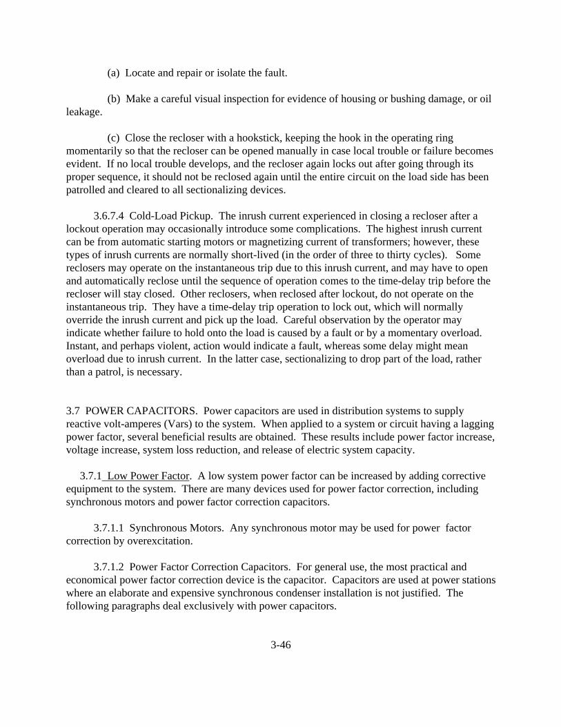
(a) Locate and repair or isolate the fault.
(b) Make a careful visual inspection for evidence of housing or bushing damage, or oilleakage.
(c) Close the recloser with a hookstick, keeping the hook in the operating ringmomentarily so that the recloser can be opened manually in case local trouble or failure becomesevident. If no local trouble develops, and the recloser again locks out after going through itsproper sequence, it should not be reclosed again until the entire circuit on the load side has beenpatrolled and cleared to all sectionalizing devices.
3.6.7.4 Cold-Load Pickup. The inrush current experienced in closing a recloser after alockout operation may occasionally introduce some complications. The highest inrush currentcan be from automatic starting motors or magnetizing current of transformers; however, thesetypes of inrush currents are normally short-lived (in the order of three to thirty cycles). Somereclosers may operate on the instantaneous trip due to this inrush current, and may have to openand automatically reclose until the sequence of operation comes to the time-delay trip before therecloser will stay closed. Other reclosers, when reclosed after lockout, do not operate on theinstantaneous trip. They have a time-delay trip operation to lock out, which will normallyoverride the inrush current and pick up the load. Careful observation by the operator mayindicate whether failure to hold onto the load is caused by a fault or by a momentary overload. Instant, and perhaps violent, action would indicate a fault, whereas some delay might meanoverload due to inrush current. In the latter case, sectionalizing to drop part of the load, ratherthan a patrol, is necessary.
3.7 POWER CAPACITORS. Power capacitors are used in distribution systems to supplyreactive volt-amperes (Vars) to the system. When applied to a system or circuit having a laggingpower factor, several beneficial results are obtained. These results include power factor increase,voltage increase, system loss reduction, and release of electric system capacity.
3.7.1 Low Power Factor. A low system power factor can be increased by adding correctiveequipment to the system. There are many devices used for power factor correction, includingsynchronous motors and power factor correction capacitors.
3.7.1.1 Synchronous Motors. Any synchronous motor may be used for power factorcorrection by overexcitation.
3.7.1.2 Power Factor Correction Capacitors. For general use, the most practical andeconomical power factor correction device is the capacitor. Capacitors are used at power stationswhere an elaborate and expensive synchronous condenser installation is not justified. Thefollowing paragraphs deal exclusively with power capacitors.
3-46

3.7.2 Ratings. Capacitors are rated in continuous kVar (kilovolt-ampere-reactive), voltage,and frequency. They are designed to give not less than rated and not more than 135 percent ratedkVar when operated at rated voltage and frequency. Capacitor units are normally available involtage ratings of 2,400 V to 34,500 V and kVar ratings from 15 kVar to 300 kVar. Variousmanufacturers' medium-voltage units up to 200 kVar are interchangeable. Capacitors aregenerally rated at a frequency of 60 Hertz (Hz), however, they are also suitable for operation atfrequencies below 60 Hz. There is no physical limit to the under-frequency operation of thecapacitors. The limit is economic, in that the capacitor kVar output is directly proportional tofrequency and applied voltage. If a capacitor is operated at a frequency lower than rated,consequently, its kVar rating is reduced. Since capacitors are installed in theory to utilize theirrated capacity, utilization at reduced frequencies is not economical, as the unit's design rating cannever be achieved.
3.7.3 Construction. A capacitor unit consists of two aluminum foil strips or plates with thinhigh-grade insulating paper or a synthetic film placed between them. The strips or plates arecompactly wound and connected in groups, each of which is connected to a terminal. There is nocontact between the two metal surfaces. When these two surfaces are connected to a source ofpower, energy is stored in the capacitor. The capacitor remains charged at, or above, full linevoltage when disconnected from the source of power until a discharge path is provided betweenthe terminals. Capacitors have a built-in discharge resistor designed to drain off or reduce thisresidual charge. National Electrical Code requires capacitors rated 600 V or more to bedischarged to a residual voltage of 50 V or less in 5 minutes. Since the built-in resistor has thedisadvantage that it cannot be visually inspected for an open circuit, it should not be relied uponfor positive drain-off of the residual charge (see subparagraph 3.7.9). The wound plates anddischarge resistor of a capacitor are enclosed in a welded sheet steel or stainless steel container,which is hermetically sealed to protect the capacitor from deterioration due to entrance of foreignmaterial or moisture. The contents are vacuum dried and are usually impregnated with adielectric fluid. As of 1 October 1977, dielectric fluids containing polychlorinated biphenyls(PCBs) can no longer be installed. The connecting leads from the capacitor are brought upthrough the bushings to a joint at the top directly under the brazed terminal. The bushingssupplied on capacitors are usually made of porcelain. As of 1 October 1988, existing PCBcapacitors in unrestricted areas must be removed.
3.7.4 Types of Installations. The greatest electrical benefits are derived from capacitorsconnected directly at the loads. This would permit maximum loss reduction and released linecapacity. However, economics and physical limitations are usually the governing factors. Capacitors may be divided into two classes, primary capacitors and secondary capacitors. Primary capacitors are those rated 2400 V and above and secondary capacitors are those used onthe low-voltage side of distribution transformers or at motor terminals and are normally rated 600V and below. The three most common types of power capacitor installation are: pole-mounted,metal-enclosed, and open-rack.
3-47
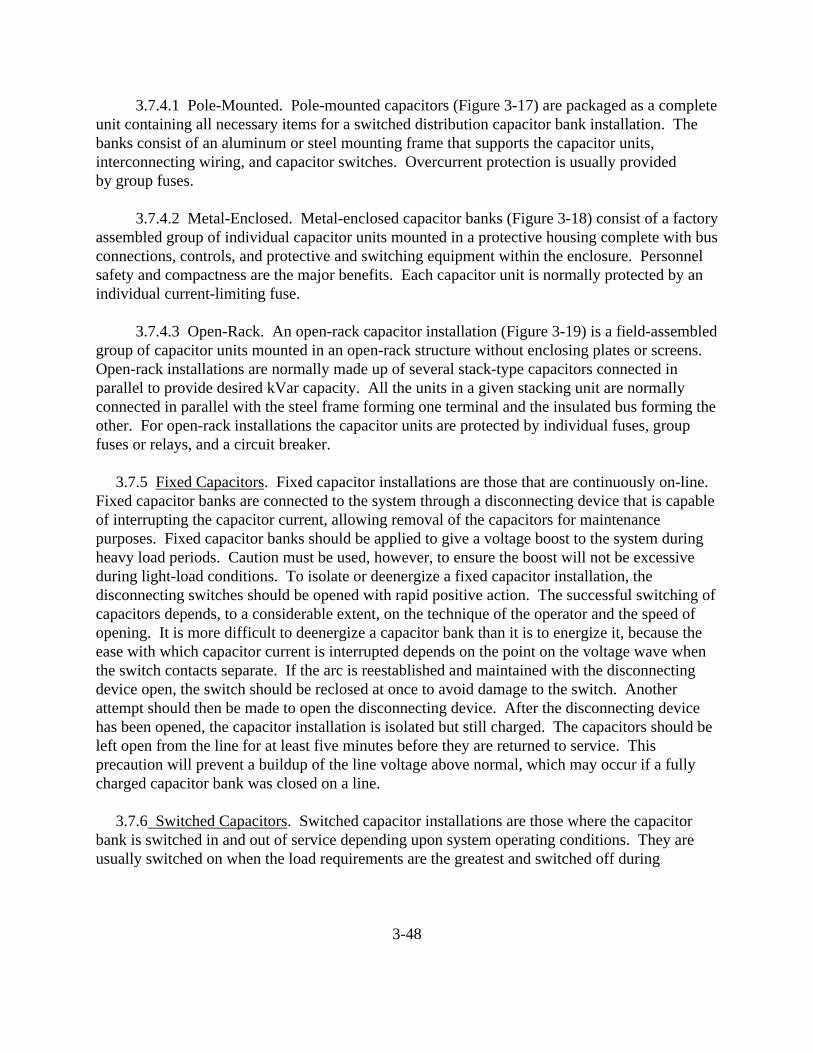
3.7.4.1 Pole-Mounted. Pole-mounted capacitors (Figure 3-17) are packaged as a completeunit containing all necessary items for a switched distribution capacitor bank installation. Thebanks consist of an aluminum or steel mounting frame that supports the capacitor units,interconnecting wiring, and capacitor switches. Overcurrent protection is usually providedby group fuses.
3.7.4.2 Metal-Enclosed. Metal-enclosed capacitor banks (Figure 3-18) consist of a factoryassembled group of individual capacitor units mounted in a protective housing complete with busconnections, controls, and protective and switching equipment within the enclosure. Personnelsafety and compactness are the major benefits. Each capacitor unit is normally protected by anindividual current-limiting fuse.
3.7.4.3 Open-Rack. An open-rack capacitor installation (Figure 3-19) is a field-assembledgroup of capacitor units mounted in an open-rack structure without enclosing plates or screens. Open-rack installations are normally made up of several stack-type capacitors connected inparallel to provide desired kVar capacity. All the units in a given stacking unit are normallyconnected in parallel with the steel frame forming one terminal and the insulated bus forming theother. For open-rack installations the capacitor units are protected by individual fuses, groupfuses or relays, and a circuit breaker.
3.7.5 Fixed Capacitors. Fixed capacitor installations are those that are continuously on-line. Fixed capacitor banks are connected to the system through a disconnecting device that is capableof interrupting the capacitor current, allowing removal of the capacitors for maintenancepurposes. Fixed capacitor banks should be applied to give a voltage boost to the system duringheavy load periods. Caution must be used, however, to ensure the boost will not be excessiveduring light-load conditions. To isolate or deenergize a fixed capacitor installation, thedisconnecting switches should be opened with rapid positive action. The successful switching ofcapacitors depends, to a considerable extent, on the technique of the operator and the speed ofopening. It is more difficult to deenergize a capacitor bank than it is to energize it, because theease with which capacitor current is interrupted depends on the point on the voltage wave whenthe switch contacts separate. If the arc is reestablished and maintained with the disconnectingdevice open, the switch should be reclosed at once to avoid damage to the switch. Anotherattempt should then be made to open the disconnecting device. After the disconnecting devicehas been opened, the capacitor installation is isolated but still charged. The capacitors should beleft open from the line for at least five minutes before they are returned to service. Thisprecaution will prevent a buildup of the line voltage above normal, which may occur if a fullycharged capacitor bank was closed on a line.
3.7.6 Switched Capacitors. Switched capacitor installations are those where the capacitorbank is switched in and out of service depending upon system operating conditions. They areusually switched on when the load requirements are the greatest and switched off during
3-48

FIGURE 3-17. POLE MOUNTED CAPACITOR(REPRODUCED COURTESY OF MCGRAW-EDISON COMPANY)
FIGURE NOT INCLUDED
3-49

FIGURE 3-18. METAL-ENCLOSED CAPACITOR BANK(REPRODUCED COURTESY OF MCGRAW-EDISON COMPANY)
FIGURE NOT INCLUDED
3-50

FIGURE 3-19. OPEN-RACK CAPACITOR INSTALLATION(REPRODUCED COURTESY OF MCGRAW-EDISON COMPANY)
FIGURE NOT INCLUDED
3-51

light-load conditions. Sometimes the capacitor banks are installed to enable incrementalswitching, depending on the system reactive requirements and the amount of system voltagerequired. To remove a switched capacitor bank from service, the control box should be openedand the automatic control lever or control switch should be placed in the off position. The circuitbreaker or the switching device should then be tripped. To ensure the circuit breaker orswitching device remains open, the fuses should be removed from the control circuit. Before itcan be assumed that the capacitor bank has been deenergized, the position of the switchingdevice should be inspected. On a circuit breaker, the position indicator should be checked. Foroil switches, the position of the operating handle can be checked with a switch stick.
3.7.7 Types of Switching Devices. Switching capacitors imposes severe duty on switchingdevices because of the differences in phase relationship between the current and voltage on acapacitor circuit. When a capacitor bank is energized, high transient overvoltages andhigh-frequency transient inrush currents may be produced. The magnitude of the transientovervoltages may easily be three times the rated line voltage, and transient inrush currents mayapproach the short-circuit current duty values. These factors are especially important when oneor more capacitor banks is already energized and another one at the same location is switched onto the bus. The methods for determining the values of inrush current, transient overvoltage andresonant frequency of the circuit are discussed in more detail in ANSI C37.99, IEEE Guide forProtection of Shunt Capacitor Banks, and ANSI C37.012, Application Guide for CapacitanceCurrent Switching of AC High-Voltage Circuit Breakers Rated on a Symmetrical Current Basis.
Switching devices, as discussed below, have a separate capacitive switching rating for thereasons mentioned above, and the switching rating of the device must be at least 135 percent ofthe capacitor bank rating to which the switching device is connected. This rating is a minimumspecified by the National Electric Code, and includes allowances for operation at overvoltage,allowance for capacitance manufacturing tolerance, and allowance for harmonic componentsabove the fundamental frequency. Some common types of switching devices used on capacitorbanks are discussed in the following paragraphs.
3.7.7.1 Indoor Circuit Breakers. Metal-enclosed capacitor equipment on circuits 13.8 kV,or below, often use indoor air or oil circuit breakers. These breakers are housed in a separatecompartment to protect them from the weather and to increase operating personnel safety.
3.7.7.2 Outdoor Circuit Breakers. On large open-rack outdoor installations, outdoor oilcircuit breakers are usually used. In some cases, the interrupting chambers of these breakers ismodified to ensure proper switching of the capacitive load by controlling prestrikes whenenergizing or restrikes when interrupting.
3.7.7.3 Oil Switches. Single-phase or three-phase oil switches are often used onpole-mounted or metal-enclosed capacitor banks. These switches are generally solenoid ormotor-operated and do not have fault interrupting capability.
3-52

3.7.7.4 Load Interrupter Switches. A load interrupter switch is employed for capacitorswitching. The most common types are air, gas-filled, and vacuum switches. These devices donot provide fault protection and are backed up by fuses or circuit breakers.
3.7.7.5 Fused Cutouts. On small fixed installations, fused cutouts are sometimes used toperform the switching operation.
3.7.8 Control Devices. Switched capacitor bank control systems initiate the switching of thecapacitors into, or out of, the circuit at predetermined conditions. The auxiliary components ofthe controls include sensors, circuit breakers or switches, and the control power source. Thecontrols normally include an automatic control lever or control switch that permits the operationof each capacitor switch either by manual operation of its control switch or in response to asignal initiated by a sensor. The most commonly used inputs for capacitor bank control are time,voltage, current, and load kVar.
3.7.8.1 Time Switch Control. Time switch or time clock control is often used with smallswitched capacitor banks. Time control switches the capacitor bank on at a certain time of theday and off at a later time. A carry-over device is normally used for each time clock to keep theclock running during temporary power outages. If a carry-over device is not used, it will benecessary for the operator to go to each capacitor location that is affected and reset the clock aftera power outage.
3.7.8.2 Voltage Control. Voltage control is widely used for capacitor switching insubstation applications. It is generally used to correct steady-state undervoltage conditionscaused by heavy circuit loading, or inadequate voltage regulation from upstream transformersand line regulators. Voltage control includes a voltage-sensitive relay, and time-delay andauxiliary relays to open and close the capacitor switching device in response to predeterminedvalues of steady-state circuit voltage. The time-delay relay is incorporated so that the switchingoperation is not initiated for momentary line voltage dips, that may be caused by a lightningstrike, a momentary dip caused by a line fault, or by a large motor load starting on a downstreambus.
3.7.8.3 Current Control. Current control is often used on regulated circuits where voltagecannot be used for capacitor switching. Voltage control includes a current-sensitive relay plustime-delay and auxiliary relays to open and close the capacitor switching device in response topredetermined values of load current.
3.7.8.4 Kilovar Control. The capacitor bank will be energized at a certain value of laggingpower factor. It will be switched off at a lower value or when there is leading power factor. Kilovar control is used to reduce peak kVar loads.
3.7.8.5 Combined Controls. Combined controls can be used for more complex situations.
3-53
For example, kVar control can be used to maintain a power factor value and voltage control canbe incorporated as an override to remove the bank under abnormal voltage conditions.
3.7.9 Service Conditions. The life of a capacitor unit is shortened by overvoltage,overheating, chemical change, physical damage, and repeated temperature changes.
3.7.9.1 Operating and Ambient Temperatures. Capacitor units are suitable for continuousoperation with an ambient temperature range of -40�C to +46�C. When ambient airtemperatures higher than 46�C are expected, forced circulation of air may be used. Normally,the maximum surface temperature of an individual capacitor unit is used to indicate theoperating-temperature condition. The temperature (at any point on the case), generally shouldnot exceed 55�C (131�F) under usual operating conditions or 70�C (158�F) under emergencyoperating conditions. Capacitor units may be operated continuously at ambient temperatures aslow as -40�C. When energizing capacitors after they have been deenergized for a period of time,the temperature of the capacitor unit should be considered. There is a risk of damage to capacitorunits if they are energized at temperatures less than -20�C.
3.7.9.2 Operating Voltage. Capacitors cause a voltage rise at their application point. Thus, capacitors are more likely to operate at overvoltages than equipment that causes voltagedrop at its application point. The maximum permissible working voltage of power capacitors is110 percent of rated voltage. Because the kVAR rating of a capacitor varies as does the square ofthe ratio of the applied voltage to the rated voltage, applied voltage must be nominally limited torated voltage. Operation of capacitors above rated voltage increases capacitor kVAR, whichfurther increases the voltage level. Under emergency conditions, however, capacitors may beoperated above 110 percent of rated voltage. The recommended maximum rms overvoltagewithout loss of capacitor life is dependent on the duration of each overvoltage. Table 3-2 liststhe recommended limits of overvoltage, expressed as a percent of rated voltage, versus the timeduration of the overvoltage condition. For example, a capacitor could be applied at 2.2 timesrated voltage for a period of one second without incurring any loss of usable life. Therecommended overvoltage limits are listed in Table 3-2.
Large capacitor banks are usually protected by fuses located (or installed) at each capacitor. Fusing provides each capacitor with proper protection and also allows partial operation of thebank when an individual capacitor fails. The fuse also serves to indicate unit failure. When alarge shunt capacitor bank is made up of series-connected groups of parallel units, the removal ofone or more units from a group will cause overvoltages on the remaining units. The failure rateof capacitor units increases rapidly when subjected to overvoltage. Some type of protection is,therefore, normally installed on large banks. This protection disconnects the bank from thesystem or sounds an alarm when a significant number of units have been removed from service. There are several schemes used to provide this protection. Most schemes require potential orcurrent transformers on the capacitor bank neutral.
3-54
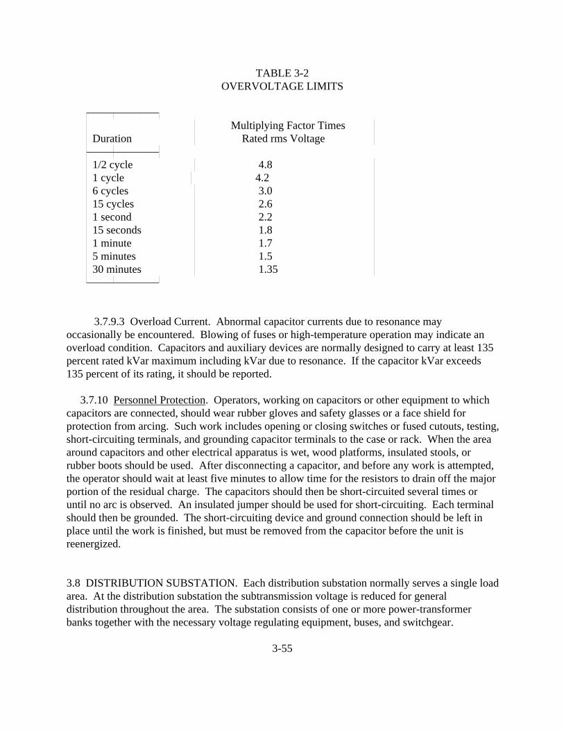
TABLE 3-2OVERVOLTAGE LIMITS
������������������������������������������������������������������ � � Multiplying Factor Times � � Duration � Rated rms Voltage � ������������������������������������������������������������������ � 1/2 cycle � 4.8 � � 1 cycle � 4.2 � � 6 cycles � 3.0 � � 15 cycles � 2.6 � � 1 second � 2.2 � � 15 seconds � 1.8 � � 1 minute � 1.7 � � 5 minutes � 1.5 � � 30 minutes � 1.35 � ����������������������������������������������������������������
3.7.9.3 Overload Current. Abnormal capacitor currents due to resonance mayoccasionally be encountered. Blowing of fuses or high-temperature operation may indicate anoverload condition. Capacitors and auxiliary devices are normally designed to carry at least 135percent rated kVar maximum including kVar due to resonance. If the capacitor kVar exceeds135 percent of its rating, it should be reported.
3.7.10 Personnel Protection. Operators, working on capacitors or other equipment to whichcapacitors are connected, should wear rubber gloves and safety glasses or a face shield forprotection from arcing. Such work includes opening or closing switches or fused cutouts, testing,short-circuiting terminals, and grounding capacitor terminals to the case or rack. When the areaaround capacitors and other electrical apparatus is wet, wood platforms, insulated stools, orrubber boots should be used. After disconnecting a capacitor, and before any work is attempted,the operator should wait at least five minutes to allow time for the resistors to drain off the majorportion of the residual charge. The capacitors should then be short-circuited several times oruntil no arc is observed. An insulated jumper should be used for short-circuiting. Each terminalshould then be grounded. The short-circuiting device and ground connection should be left inplace until the work is finished, but must be removed from the capacitor before the unit isreenergized.
3.8 DISTRIBUTION SUBSTATION. Each distribution substation normally serves a single loadarea. At the distribution substation the subtransmission voltage is reduced for generaldistribution throughout the area. The substation consists of one or more power-transformerbanks together with the necessary voltage regulating equipment, buses, and switchgear.
3-55

3.8.1 Substation Grounding. In the past, substation grounding has been taken for granted andhas even been ignored. The large growth of the electrical system and the number ofinterconnections with the power suppliers increase the ground fault current and the probability ofelectric shock when substation equipment is not grounded.
Utilization of sound engineering principles is required for acceptable substation groundingproviding a safe and shockproof grid around the substation. The old practice of installing just afew conductors for a substation grid around the substation transformer is no longer acceptable.
The four steps presented on the following pages (soil resistivity test, maximum ground faultcurrent, design of grid, and measurement of soil resistivity) are all necessary functions to ensuresafety around the substation.
3.8.1.1 Soil Resistivity Test. Preliminary designs of substations should include aninvestigation of the general soil type to aid in foundations design. Any such investigation willindicate a rough approximation of the soil resistivity similar to the typical values shown inTable 3-3. Testing soil samples in the lab, the three pin method, and the four pin method arethree procedures used to determine soil resistivity in the substation lot.
3.8.1.2 Maximum Ground Fault Current. The value of maximum ground fault currentmust be calculated for use in the substation ground design. An allowance for future growthshould be made, and an adjustment should also be made for the effect of direct current offset andattenuation of alternating current and direct current transient components of fault current.
3.8.1.3 Grid Design. The preliminary design of the station grounding should consist ofplacing and noting of all the required grounding. The following is a list of the groundingrequirements normally found in substations.
(a) Power transformers require two grounds, each capable of carrying full fault current.
(b) Lightning arresters require one ground connected from the grid directly to thelightning arrester base. The ground must be capable of carrying the discharge.
(c) Dead-end towers normally require one ground per each leg connected to thestructure.
(d) The following items or structures require a minimum of one ground per each leg:
o Switch Stand. o Bus Support Structures. o Potential and Current Transformers. o Coupling Capacitors. o All Miscellaneous Structures.
3-56
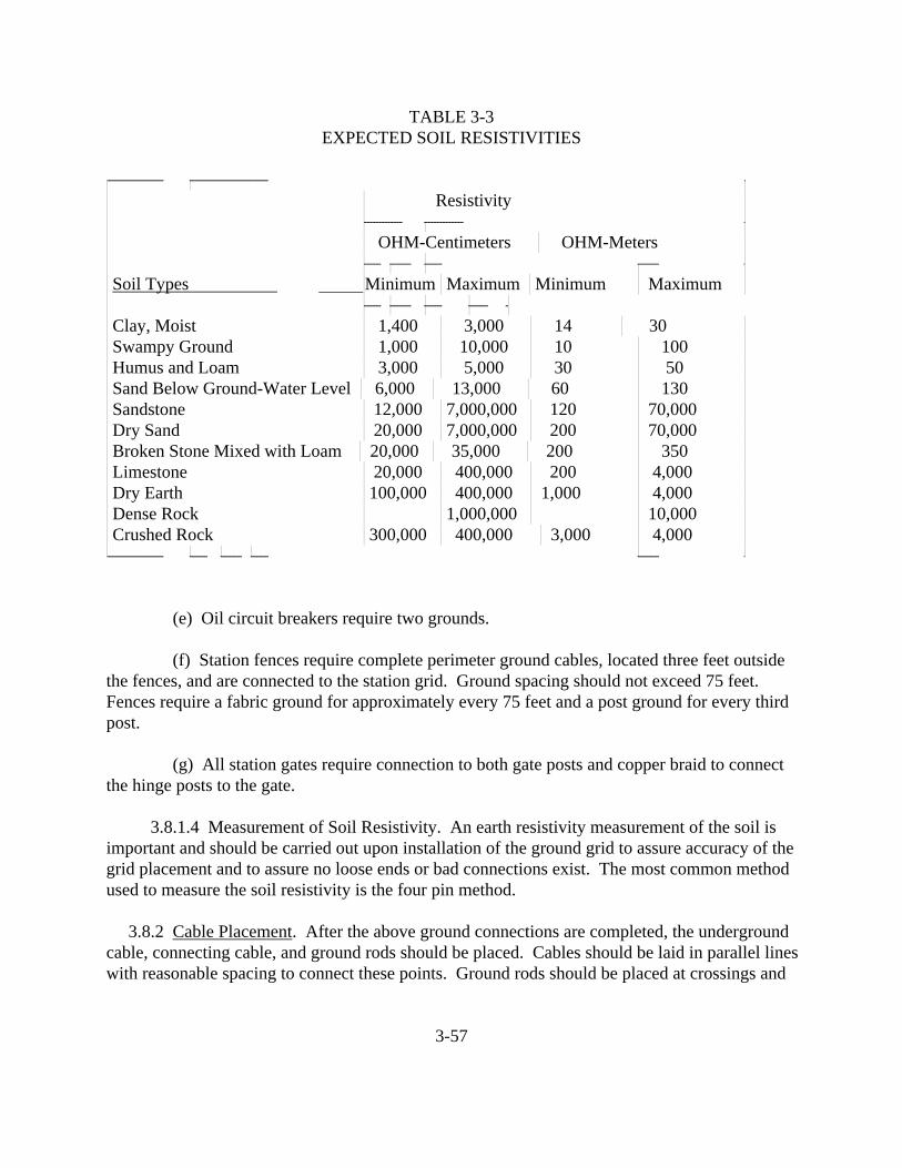
TABLE 3-3EXPECTED SOIL RESISTIVITIES
�������������������������������� �������������������������������������������� �� � Resistivity �� ���������������������� ���������������������� �� � OHM-Centimeters � OHM-Meters �� ���������� ������������ ���������� ������������ �� Soil Types �Minimum � Maximum � Minimum � Maximum �� ���������� ������������ ���������� ����������� ��� Clay, Moist � 1,400 � 3,000 � 14 � 30 �� Swampy Ground � 1,000 � 10,000 � 10 � 100 �� Humus and Loam � 3,000 � 5,000 � 30 � 50 �� Sand Below Ground-Water Level � 6,000 � 13,000 � 60 � 130 �� Sandstone � 12,000 � 7,000,000 � 120 � 70,000 �� Dry Sand � 20,000 � 7,000,000 � 200 � 70,000 �� Broken Stone Mixed with Loam � 20,000 � 35,000 � 200 � 350 �� Limestone � 20,000 � 400,000 � 200 � 4,000 �� Dry Earth � 100,000 � 400,000 � 1,000 � 4,000 �� Dense Rock � � 1,000,000 � � 10,000 �� Crushed Rock � 300,000 � 400,000 � 3,000 � 4,000 �������������������������������� ��������� ����������� ��������� ����������� �
(e) Oil circuit breakers require two grounds.
(f) Station fences require complete perimeter ground cables, located three feet outsidethe fences, and are connected to the station grid. Ground spacing should not exceed 75 feet. Fences require a fabric ground for approximately every 75 feet and a post ground for every thirdpost.
(g) All station gates require connection to both gate posts and copper braid to connectthe hinge posts to the gate.
3.8.1.4 Measurement of Soil Resistivity. An earth resistivity measurement of the soil isimportant and should be carried out upon installation of the ground grid to assure accuracy of thegrid placement and to assure no loose ends or bad connections exist. The most common methodused to measure the soil resistivity is the four pin method.
3.8.2 Cable Placement. After the above ground connections are completed, the undergroundcable, connecting cable, and ground rods should be placed. Cables should be laid in parallel lineswith reasonable spacing to connect these points. Ground rods should be placed at crossings and
3-57
should be as close as possible to transformers, lightning arresters, and ground switches, butshould not be spaced closer than ten feet. Cables shall be sized accordingly:
(a) Able to resist fusing and deterioration of electric joints for the worst case faultcurrent magnitude and duration possible.
(b) Mechanically rigged to a high degree. Normally 1/0 is adequate, mechanically, forbrazed joints and 2/0 for bolted joints.
(c) Have sufficient conductivity to prevent contribution to dangerous local potentialdifferences.
3.8.3 Preventive Maintenance. Proper maintenance of line and substation equipment willreduce both unnecessary outages and operating costs. Preventive maintenance is also less costlythan maintenance that must be performed on already damaged or faulty units. Procedures formaintaining the following apparatus are discussed in detail below:
3.8.3.1 Transformers. Transformer maintenance procedures may be divided into thefollowing service classifications:
(a) Distribution Transformers:
o Check all the overhead connections monthly. o Check the oil content for PCB contamination annually. o Check oil level annually. o Check the bushings for cracks or loose contacts annually. o Obtain oil sample and perform lab tests for dielectric strength, neutralization
number, interfacial tension, and gas-in-oil analysis every two years.
(b) Substation Transformers:
o Check all the overhead connections monthly. o Check the oil content for PCB contamination annually. o Obtain oil sample and perform lab tests for dielectric strength, neutralization
number, interfacial tension, and gas-in-oil analysis annually. For arc furnace, rectifier, and on-load-tap changer type units, the frequency should be from quarterly to annually, depending on the service and history of the individual unit.
o Check the bushings for cracks or loose contacts annually. o Check the connections of incoming and outgoing overhead/underground
conductors at the bushings biannually. o Check the service transformer connection annually. o Check the fuses on the high side and the low side annually.
3-58
o Check the current and potential transformers and the disconnect switches for manual operation annually.
o Check the transformer tank, cooling fins, tubes, radiators, and all gasketed and other openings visually for any possible leaks monthly.
o Check the gauges on the transformer for oil level, oil temperature, and tank pressure weekly. Look for signs of overheating or corrosion.
o Observe any change in operating sound regularly. A louder hum than normal could indicate low oil level or temperature rise inside the tank.
(c) Dry Type Transformers:
o Retorque connections, vacuum out dirt, and blow with a maximum of 25 psi compressed air every two years.
o Check temperature and cleanliness weekly. Look for signs of overheating or corrosion.
3.8.3.2 Voltage Regulators. The following represents a maintenance checklist for voltageregulators. Each item should be spot checked on a periodic basis to ensure proper function:
(a) Check for physical damage to the tank periodically.
(b) Check the connections.
(c) Check the operation lever setting for boosting and bucking voltage.
(d) Check the accuracy of the regulator by checking the voltage across the bus with thehelp of a voltmeter.
3.8.3.3 Switches. There are several different types of switches on line and on thesubstation busses. The primary function of a switch is to open or close a feeder.
(a) Check for loose connections and proper operation biannually.
(b) Check contact surfaces biannually.
3.8.3.4 Circuit Breakers. The following represents a maintenance checklist for lowvoltage and high voltage circuit breakers. Each item should be checked every three years for lowvoltage circuit breakers, every two years for high voltage circuit breakers, and annually for highvoltage circuit breakers used in generating stations.
(a) Check mechanical and electrical operation and alignment.
3-59
(b) Check condition of contacts and measure the contact resistance.
(c) Check and tighten the connections.
3.8.3.5 Reclosers.
(a) Check the reclosing capabilities annually.
(b) Check and replace oil in the tank at least biannually.
(c) Check the physical condition of the tank periodically.
(d) Check the tripping coils for proper function, periodically.
3.8.3.6 Power Capacitors. Capacitors are usually maintenance free, although routinechecks will extend service life.
(a) Check the connections visually with regard to the conductor and servicetransformers.
(b) Check for PCB contamination annually by checking the dielectric strength.
(c) Check the tank for damage.
(d) Visually check the rack for corrosion.
(e) Manually test control operation annually.
3-60

CHAPTER 4. POWER SYSTEM PROTECTION AND COORDINATION.
4.1 SYSTEM PROTECTION METHODS. This chapter briefly presents system protectionmethods. These methods include application and coordination of components required to protectpower systems against abnormalities which are reasonably expected to occur during normalsystem operation. This chapter deals almost exclusively with the quick isolation of the affectedportion of the system.
4.1.1 System Protection and Coordination. Electrical system protection should not only besafe under all service conditions, but should also be selective to insure continuity of service. Aselective system is a system that isolates only the faulted circuit without disturbing any other partof the system. Overcurrent devices should provide short-circuit, as well as low overcurrent,protection for system components (bus, wire, motor controllers, etc.).
4.1.1.1 Definition. System protection should guard electrical equipment against thermaldamage and electromechanical stress, while providing the highest possible degree of coordinationamong protective devices. Coordination (or selectivity) of electrical protective devices isachieved when the devices react, under fault conditions, to isolate faulty equipment, whilemaintaining service to the remainder of the system.
4.1.1.2 Objectives. Protection for power systems allows for the following objectives:
(a) Personnel injury prevention.
(b) Prevention of damage to equipment.
(c) Interruption of power minimization.
(d) Minimization of the effect of faults on the system, both in extent and duration.
(e) Minimization of the effect of disturbances on the utility system.
4.1.1.3 Methods. There are several methods to minimize the effects of faults on thesystem and load. The basic features that are incorporated in the design of power systems willperform the following:
(a) Quickly isolate the affected portion of the system, while maintaining normal serviceto as much of the system as possible, and minimizing damage to the affected portion.
(b) Minimize the magnitude of the available short circuit current to minimize potentialsystem damage to the system, components, and load.
4-1
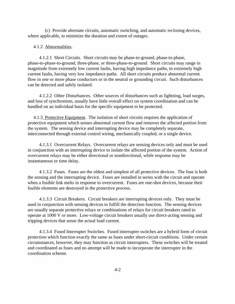
(c) Provide alternate circuits, automatic switching, and automatic reclosing devices,where applicable, to minimize the duration and extent of outages.
4.1.2 Abnormalities.
4.1.2.1 Short Circuits. Short circuits may be phase-to-ground, phase-to-phase,phase-to-phase-to-ground, three-phase, or three-phase-to-ground. Short circuits may range inmagnitude from extremely low current faults, having high impedance paths, to extremely highcurrent faults, having very low impedance paths. All short circuits produce abnormal currentflow in one or more phase conductors or in the neutral or grounding circuit. Such disturbancescan be detected and safely isolated.
4.1.2.2 Other Disturbances. Other sources of disturbances such as lightning, load surges,and loss of synchronism, usually have little overall effect on system coordination and can behandled on an individual basis for the specific equipment to be protected.
4.1.3 Protective Equipment. The isolation of short circuits requires the application ofprotective equipment which senses abnormal current flow and removes the affected portion fromthe system. The sensing device and interrupting device may be completely separate,interconnected through external control wiring, mechanically coupled, or a single device.
4.1.3.1 Overcurrent Relays. Overcurrent relays are sensing devices only and must be usedin conjunction with an interrupting device to isolate the affected portion of the system. Action ofovercurrent relays may be either directional or nondirectional, while response may beinstantaneous or time delay.
4.1.3.2 Fuses. Fuses are the oldest and simplest of all protective devices. The fuse is boththe sensing and the interrupting device. Fuses are installed in series with the circuit and operatewhen a fusible link melts in response to overcurrent. Fuses are one-shot devices, because theirfusible elements are destroyed in the protective process.
4.1.3.3 Circuit Breakers. Circuit breakers are interrupting devices only. They must beused in conjunction with sensing devices to fulfill the detection function. The sensing devicesare usually separate protective relays or combinations of relays for circuit breakers rated tooperate at 1000 V or more. Low-voltage circuit breakers usually use direct-acting sensing andtripping devices that sense the actual load current.
4.1.3.4 Fused Interrupter Switches. Fused interrupter switches are a hybrid form of circuitprotection which function exactly the same as fuses under short-circuit conditions. Under certaincircumstances, however, they may function as circuit interrupters. These switches will be treatedand coordinated as fuses and no attempt will be made to incorporate the interrupter in thecoordination scheme.
4-2

4.2 SHORT-CIRCUIT CURRENTS. This section provides a general discussion ofshort-circuit currents, focusing on circuit impedances, fault currents, and the analysis ofshort-circuit currents and interrupting ratings to coordinate protective devices.
4.2.1 Circuit Impedances. The determination of short-circuit current is dependent principallyupon the reactance (X) of the elements from the source (or sources) to the fault point. This holdstrue for all elements except cable, open-wire lines, and buses. When the ratio of reactance toresistance (X/R ratio) of the entire system from the sources to the fault is greater than 4,negligible error will result from neglecting resistance. Neglecting R introduces an error thatalways makes the calculated short-circuit current slightly larger than the actual short-circuitcurrent. It is common practice to refer to reactances (X), even when they represent impedances (Z).
4.2.2 Fault Currents. Certain simplifying assumptions are customarily made whencalculating fault current. An important assumption is that the fault is bolted; that is, it has zeroimpedance and is sustained (not intermittent). This assumption not only simplifies calculation,but also applies a safety factor, since the calculated values are a maximum and equipmentselected on this basis is rarely stressed beyond its full rating. Three-phase and single-phase faultcurrents are customarily assumed for the purpose of calculation because one of these two currentswill define the maximum short-circuit current available in a circuit, and because these currentvalues will be needed to properly coordinate phase and ground overcurrent protective devices.
4.2.2.1 Actual Fault Currents. Actual fault currents are usually less than the calculatedvalues. Bolted line-to-line currents are about 87 percent of the three-phase value, while boltedline-to-ground currents can range from a few percent to possibly 125 percent of the three-phasevalue, depending on system parameters. Line-to-ground currents of more than the three-phasevalue are rare but may occur in industrial systems. Actual faults, especially line-to-ground faults,usually involve arcing. Ground-fault currents, particularly in low-voltage systems, are often lessthan normal load currents. These currents, however, can be extremely destructive because theymay build up voltage 3 to 8 times more than normal.
4.2.2.2 Sources of Fault Current. Basic sources of fault current are: the utility supplysystem, local generators, synchronous motors, induction motors, and capacitors.
(a) A typical modern electric utility supply system represents a large and complexinterconnection of generating plants. The individual generators in a typical system are notaffected by a maximum short circuit in an industrial plant. Transmission and distribution linesand transformers introduce impedance between the utility generators and the industrial customer. Were it not for this impedance, the utility system would be an infinite source of fault current.
(b) In-plant generators react to system short circuits in a predictable way. Fault currentfrom a generator decreases exponentially from a relatively high initial value to a lower
4-3

steady-state value some time after the initiation of the fault. Since a generator continues to bedriven by its prime mover, and has its field energized from its separate exciter, the steady-statevalue of fault current will persist unless interrupted by some circuit interrupter. Most properlyapplied fault protective devices, such as circuit breakers or fuses, operate before steady-stateconditions are reached.
(c) Synchronous motors supply current to a fault in much the same manner as dosynchronous.generators. The drop in system voltage due to a fault causes the synchronous motorto receive less power from the system for driving its load. The inertia of the motor and its loadacts as a prime mover, and with field excitation maintained, the motor acts as a generator tosupply fault current. This fault current diminishes because the motor will slow down as thekinetic energy is dissipated, reducing the voltage generated, and because of the decay of motorfield excitation.
(d) The fault-current contribution of an induction motor results from generator actionproduced by inertia driving the motor after the fault occurs. In contrast to the synchronousmotor, the field flux of the induction motor is produced by induction from the stator rather thanfrom a direct current field winding. Since this flux decays on removal of source voltage resultingfrom a fault, the contribution of an induction motor drops off rapidly, ultimately disappearingcompletely upon loss of voltage. As field excitation is not maintained, there is no steady-statevalue of fault current as with synchronous machines.
(e) Capacitor discharge current, because of its very short time constant of less than onecycle, can be neglected in most cases. However, there are applications in industrial andcommercial power systems in which very high transitory short-circuit currents can be developedwhen a short circuit occurs close to a bank of energized capacitors. These transitory currents,generally of much higher frequency, may exceed in magnitude, the power-frequency short-circuitcurrents and persist long enough to impose severe duty on the circuit parts carrying this current.
4.2.2.3 Short-Circuit Current Behavior. When a short circuit occurs, a new circuit isestablished with lower impedance and the current consequently increases. In the case of a boltedshort circuit, the impedance is drastically reduced and the current increases to a very high valuein a fraction of a cycle. Figure 4-1 represents a symmetrical short-circuit current wave; that is, ashort-circuit current that has the same axis as the normal current which flowed before the faultoccurred. To produce a symmetrical short-circuit current (under the usual condition that theshort-circuit power factor be essentially zero) the fault must occur exactly when the normalvoltage is maximum. In Figure 4-1 the system voltage is assumed to remain constant, althoughthe current changes.
(a) The total short-circuit current consists of components from any source connected tothe circuit (Figure 4-2). The contributions from rotating machinery decrease at various rates. This causes the symmetrical current to decrease until a steady-state value is reached. This
4-4

decrease is known as the alternating current decrement of the short-circuit current. Figure 4-2shows a decreasing symmetrical short-circuit current.
(b) Most short-circuit currents are not symmetrical, but are offset from thenormal-current axis for several cycles. If the power factor is essentially zero until a steady-statevalue is reached and the short circuit occurs at the zero point on the voltage wave, the currentstarts to build up from zero, but cannot follow the normal-current axis because the current mustlag behind the voltage by 90�. Although the current is symmetrical with respect to a new axis, itis asymmetrical with respect to the original axis.
4-5
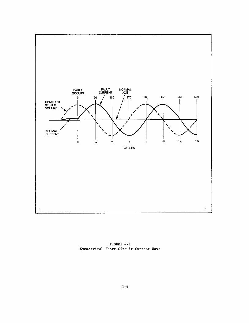
4-6
4-7

Figure 4-3 shows an asymmetrical short-circuit wave with the maximum possible asymmetry. The magnitude of current offset for a typical fault will be between the two extremes of completesymmetry and complete asymmetry, because the odds are against the fault occurring at eitherpeak or zero voltage. The offset of the asymmetrical current wave from a symmetrical wave,having equal peak-to-peak displacement, is a positive value of current that may be considered asa direct current.
The asymmetrical current, therefore, may be thought of as the sum of an alternating currentcomponent b and a direct current component a. The direct current component decreaseseventually to zero, as the stored energy it represents is expended in the form of I2�R losses inthe resistance of the system. The initial rate of decay of the direct current component isinversely proportional to the X/R ratio of the system from the source to the fault. The decaybecomes more rapid as the X/R ratio is decreased. This decay is called the direct currentdecrement. The total short-circuit current is thus affected by both an alternating current and adirect current decrement before reaching its steady-state value.
4-8

4.2.2.4 Short-Circuit Current Concepts. From the foregoing, it can be seen that theshort-circuit current behaves differently in the first few cycles than it does later (if allowed topersist). Former practice was to determine an asymmetrical value of short-circuit current byapplying simple multipliers to the calculated symmetrical value of short-circuit current. Thetrend in recent years is to rate protective equipment on a basic symmetrical value. Asymmetry isthen accounted for by various application formulas depending on the class of equipment. Recently, the concept of I2�t has been introduced to supplement the symmetrical currentconcept, because it represents the actual thermal and magnetic stresses imposed on equipmentcarrying short-circuit current in the first few cycles. The quantity I2�t represents the timeintegral of the current squared for the time under consideration. An I2�t rating is being appliedincreasingly to electrical apparatus. Conceivably, all future protective equipment may becoordinated on an I2�t basis rather than a maximum current basis.
4.2.3 Analysis. The maximum magnitude of short-circuit current, as well as adequateinterrupting ratings, must be known in order to coordinate protective devices. For coordination,minimum as well as maximum values may be required. Furthermore, it is often necessary toknow the maximum let-through current to verify the withstand capability of circuit elements inseries with the fault.
4.2.3.1 Withstand Capability. The fault current varies with time after the fault. Aprotector, that does not interrupt until several cycles after initiation of the fault, usually allowsthe fault current to decay from its maximum asymmetrical value. The protector and all seriesdevices, however, must withstand the maximum current as well as the total dissipated energy. Aprotective device which interrupts in a fraction of a cycle (before maximum fault current isattained) reduces the withstand requirements of series devices.
4.2.3.2 Calculations. Short-circuit currents may be calculated at the followingrecommended times:
(a) First-cycle maximum symmetrical values are always required. They are often theonly values needed for low-voltage breakers with instantaneous trip devices and for fuses ingeneral.
(b) Maximum values (1.5 to 4 cycles) are required for medium-and high-voltage circuitbreaker application.
(c) Reduced fault current values (about 30 cycles) are needed for estimating theperformance of time-delay relays and fuses and for low-voltage power circuit breakers withoutinstantaneous trip devices. They must often be calculated after the fault has initiated so that theproper current is known for setting time delayed protective relays. Often, minimum values mustalso be calculated to determine whether sufficient current is available to open the protectivedevice within a satisfactory time.
4-9

4.3 RELAYS. This section provides a general discussion of protective relay systems anddescribes the various types of relays used for short-circuit protection.
4.3.1 Protective Relay Systems. Protective relay systems are intended to detect abnormalconditions and to isolate them by initiating the operation of circuit breakers or other devices. Normally, relays operate power circuit breakers rated above 600 V. The most common conditionfor which protection is required is the short circuit. There are many other conditions, however,which also require protection. These conditions include undervoltage, overvoltage, open-phase,overcurrent, unbalanced phase currents, reverse power flow, underfrequency, overfrequency, andovertemperature.
The basic relay types most commonly used in power systems are: overcurrent, directional,differential, current phase-balance, ground-fault, synchronism check and synchronizing,pilot-wire, voltage, distance, phase-sequence or reverse-phase, frequency, temperature, pressure,and auxiliary relays. Following is a brief description of the characteristics and applications ofthe various relay types.
4.3.2 Overcurrent Relays. The most common relay for short-circuit protection of theindustrial power system is the overcurrent relay. Overcurrent relays used in the industry aremostly of the electromagnetic attraction, induction, and solid-state types.
4.3.2.1 Electromagnetic Attraction. The simplest overcurrent relay using theelectromagnetic attraction principle is the solenoid type. The basic elements of this relay are asolenoid wound around an iron core and steel plunger or armature which moves inside thesolenoid and supports the moving contacts.
4.3.2.2 Induction. The induction overcurrent relay is similar to a watt-hour meter since itconsists of an electromagnet and a movable armature which is usually a metal disk on a verticalshaft restrained by a coiled spring. The relay contacts are operated by the movable armature.
4.3.2.3 Operating Current. The pickup or operating current for all overcurrent relays isadjustable. When the current through the relay coil exceeds a given setting, the relay contactsclose and initiate the circuit breaker tripping operation. The relay operates as a burden to acurrent transformer.
4.3.2.4 Operating Time. If the current operates the relay without intentional time delay,the protection is called instantaneous overcurrent protection. When the overcurrent is of atransient nature, such as caused by the starting of a motor or some sudden overload of briefduration, the circuit breaker should not open. For this reason most overcurrent relays areequipped with a time delay which permits a current several times the relay setting to persist for alimited period of time without closing the contacts. If a relay operates faster as currentincreases, it is said to have an inverse-time characteristic. Overcurrent relays are available with
4-10

inverse-, very inverse-, and extremely inverse-time characteristics to fit the requirements of theparticular application. There are also definite minimum-time overcurrent relays having anoperating time that is practically independent of the magnitude of current after a certain currentvalue is reached. Induction overcurrent relays have a provision for variation of the timeadjustment and permit change of operating time for a given current. This adjustment is calledthe time lever or time dial setting of the relay. It is possible to adjust the operating time of relaysto selectively trip circuit breakers which operate in series on the same circuit.
4.3.2.5 Overcurrent Relays with Voltage Restraint or Voltage Control. A short circuit onan electric system is always accompanied by a corresponding large voltage dip, whereas anoverload will cause only a moderate voltage drop. A voltage-restrained overcurrent relay isdesigned to operate at lower current values when the system voltage drops below its nominalvalue. A voltage-controlled relay will not operate until the system voltage drops below apredetermined setting, as would occur during a short circuit.
4.3.3 Directional Relays.
4.3.3.1 Directional Overcurrent Relays. Directional overcurrent relays consist of a typicalovercurrent unit and a directional unit combined to operate together for a predeterminedphase-angle and magnitude of current. The current in one coil is compared in phase-angleposition with a voltage or current in another coil of that unit. The reference current or voltage iscalled the polarization. The relay operates only for current flow in one direction and will beinsensitive to current flow in the opposite direction.
4.3.3.2 Directional Ground Relays. The grounded-neutral industrial power system mayuse directional ground relays, constructed much the same as the directional overcurrent relays. Inorder to properly sense the direction of fault current flow, directional ground relays require apolarizing source which may be either potential or current, as the situation requires.
4.3.3.3 Directional Power Relays. The directional power relay is, in principle, asingle-phase or three-phase contact-making wattmeter and operates at a predetermined value ofpower. It is often used as a directional overpower relay set to operate if excess energy flows outof an industrial power system into the utility power system. Under certain conditions it may alsobe useful as an underpower relay to separate the two systems if the power flow drops below apredetermined value. It is also used to disconnect a generator operating in parallel with a largergenerator or a utility, should the prime mover's fuel supply be interrupted.
4.3.4 Differential Relays. All the previously described relays have the common characteristicof adjustable settings to operate at a given value of some electrical quantity such as current,voltage, or power. There are other fault-protection relays which function by virtue of continuallycomparing two or more currents. Certain fault conditions will cause a difference in thesecompared values and the resulting differential current can be used to operate the relay. Current
4-11

transformers, however, have a small error in ratio and phase angle between the primary andsecondary currents, depending upon variations in manufacture, the magnitude of current, and theconnected secondary burden. These errors will cause a differential current to flow even when theprimary currents are balanced. The error current may become proportionately larger during faultconditions, especially when there is a direct current component present in the fault current. Thedifferential relays, of course, must not operate for the maximum error current which can flow fora fault condition external to the protected zone. To provide this feature, the percentagedifferential relay has special restraint windings to prevent improper operation due to the errorcurrent on heavy through-fault conditions while providing very sensitive detection oflow-magnitude faults inside the differentials protected zone.
4.3.5 Current Phase-Balance Relays. In some cases phase-balance current relays can providean acceptable substitute for differential protection. A negative-sequence current relay is a moresensitive device that also detects unbalanced phase currents. In applying these relays it isassumed that under normal conditions the phase currents in the three-phase supply to theequipment and the corresponding output signals from each phase current transformer arebalanced. Should the fault occur in the motor or generator involving one or two phases or shouldan open circuit develop in any of the phases, the currents will become unbalanced and the relaywill operate. In addition to protecting against winding faults, the phase-balance current relayaffords protection against damage to the motor or generator due to single-phase operation.
4.3.6 Ground-Fault Relays. Ground-fault relays may be used to provide improved protectionwhen the power system is intentionally grounded and ground-fault current can flow through theconductors. This is often an overcurrent relay connected to sense the resultant current (vectorsummation of currents through all conductors of a feeder) or the current flow through thegrounded conductor. The ground relay can be set to pick up at a much lower current value thanthe phase relays, because the vector summation of the currents flowing through the conductors ofa feeder is normally zero. Overcurrent relays used for ground-fault protection are generally thesame as those used for phase-fault protection, except that a more sensitive range of minimumoperating current values is possible since they see only fault currents and not load currents. Relays with inverse-, very inverse-, and extremely inverse-time characteristics, as well asinstantaneous relays, are all applicable as ground-fault relays.
4.3.7 Synchronism-Check and Synchronizing Relays.
4.3.7.1 Synchronism-Check Relays. The synchronism-check relay is used to verify thattwo alternating current sources are within the desired limits of frequency, voltage, and phaseangle to operate in parallel. Synchronism-check relays should be employed for switchingapplications on systems known to be normally paralleled at some other location. When usedfor these applications, synchronous relays ensure the two sources have not become electricallyseparated or displaced by an unacceptable phase angle.
4-12

4.3.7.2 Synchronizing Relays. The synchronizing relay monitors two separate systemsthat are to be paralleled. It automatically initiates switching when the phase-angle displacement,frequency difference, voltage deviation, and the operating time of the switching equipment (toaccomplish interconnection) are acceptable.
4.3.8 Pilot-Wire Relays. The relaying of tie lines, either between the industrial system andthe utility system or between major load centers within the industrial system, often present aspecial problem. Such lines must be capable of carrying maximum emergency load currents forany length of time and they must be easily and quickly removed from service when a faultoccurs. A type of differential relaying called pilot-wire relaying responds very quickly to faultsin the protected line. It clears the fault promptly and minimizes line damage and disturbance tothe system, yet is normally unresponsive to load currents and to currents flowing to faults in otherlines and equipment. The various types of pilot-wire relaying schemes all operate on theprinciple of comparing the conditions at the terminals of the protected line. The relays areconnected to operate if the comparison indicates a fault in the line. The information necessaryfor this comparison is transmitted between terminals over a pilot-wire circuit.
4.3.9 Voltage Relays. Voltage relays actuate at predetermined values of voltage, which maybe.overvoltage, undervoltage, a combination of both, voltage unbalance (comparing two sourcesof voltage), reverse phase voltage, and excess negative-sequence voltage (single phasing of athree-phase system). Adjustments for pickup or dropout voltage and operation timing are usuallyprovided in these relays. Time-delay is often required to preclude nuisance relay operation bytransient voltage disturbances.
4.3.10 Distance Relays. Distance relays comprise a family of relays that respond to voltageand current in terms of impedance. This impedance represents an electrical measure of thedistance along a transmission line from the relay location to a fault. The impedance can alsorepresent the equivalent impedance of a generator or large synchronous motor when adistance relay is used for loss-of-field protection. Three main types of distance relay and theirusual applications are as follows:
4.3.10.1 Impedance-Type. Impedance-type relays provide phase-fault relaying formoderate-length lines.
4.3.10.2 Mho-Type. Mho-type relays provide phase-fault relaying for long lines andgenerator or large synchronous motor loss-of-field relaying.
4.3.10.3 Reactance-Type. Reactance-type relays provide ground-fault relaying andphase-fault relaying on very short lines.
4.3.11 Phase-Sequence or Reverse-Phase Relays. Reversal of the phase rotation of a motormay result in costly damage to machines, periods of lengthy shutdown, and production loss.
4-13
Critical motors are frequently equipped with phase-sequence or reverse-phase relay protection. When connected to a suitable potential source, phase-sequence and reverse-phase relays closetheir contacts on reversal of phase rotation. These relays also can be used to sense unbalancedvoltage or undervoltage conditions.
4.3.12 Frequency Relays. Frequency relays sense underfrequency or overfrequencyconditions during system disturbances. Most frequency relays have provision for adjustment ofoperating frequency and voltage. The speed of operation depends on the deviation of the actualfrequency from the relay setting. Some frequency relays operate instantaneously if the frequencydeviates from the set value. Others are actuated by the rate at which the frequency is changing. The usual application of this type of relay is to selectively drop system load based on thefrequency decrement in order to restore normal system stability.
4.3.13 Temperature Relays. Temperature relays usually operate in conjunction withtemperature detecting devices such as resistance temperature detectors or thermocouples locatedin the equipment to be protected and are used for protection against overheating of large motors(above 1500 hp), generator stator windings, and large transformer windings.
4.3.14 Pressure Relays. Pressure relays used in power systems respond either to the rate ofrise of gas pressure (sudden pressure relay) or to a slow accumulation of gas (gas-detector relay),or a combination of both. Such relays are valuable supplements to differential or other forms ofrelaying on power, regulating, and rectifier transformers.
4.3.15 Auxiliary Relays. Auxiliary relays are used in protection schemes whenever a singleprotective device alone cannot provide all the functions necessary for satisfactory protection. Auxiliary relays are available with a wide range of coil ratings, contact arrangements, andtripping functions, each suited for a particular application. Some of the most commonapplications of auxiliary relays are circuit breaker lockout, circuit breaker latching, targeting,multiplication of contacts, timing, circuit supervision, and alarming.
4.3.16 Relay Device Numbers and Functions. The standard device numbers assigned to themore commonly used relays and the associated functions are listed below. The numbers arefrequently used in connection diagrams, in instruction books, and in specifications.
4-14
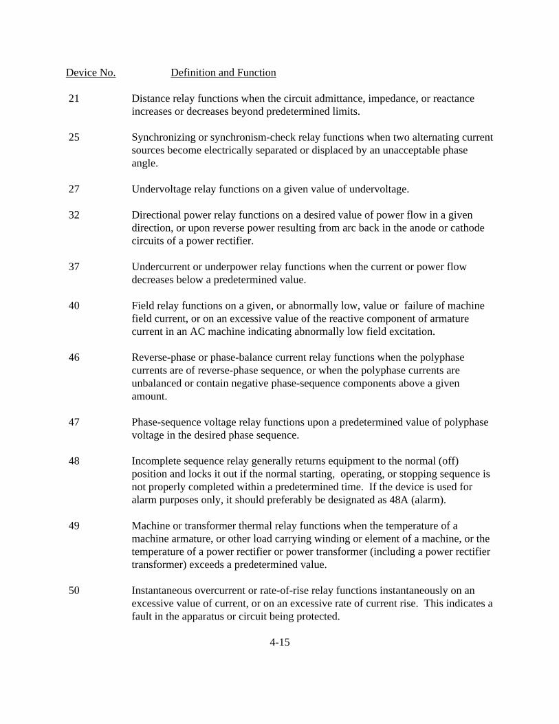
Device No. Definition and Function
21 Distance relay functions when the circuit admittance, impedance, or reactanceincreases or decreases beyond predetermined limits.
25 Synchronizing or synchronism-check relay functions when two alternating currentsources become electrically separated or displaced by an unacceptable phaseangle.
27 Undervoltage relay functions on a given value of undervoltage.
32 Directional power relay functions on a desired value of power flow in a givendirection, or upon reverse power resulting from arc back in the anode or cathodecircuits of a power rectifier.
37 Undercurrent or underpower relay functions when the current or power flowdecreases below a predetermined value.
40 Field relay functions on a given, or abnormally low, value or failure of machinefield current, or on an excessive value of the reactive component of armaturecurrent in an AC machine indicating abnormally low field excitation.
46 Reverse-phase or phase-balance current relay functions when the polyphasecurrents are of reverse-phase sequence, or when the polyphase currents areunbalanced or contain negative phase-sequence components above a givenamount.
47 Phase-sequence voltage relay functions upon a predetermined value of polyphasevoltage in the desired phase sequence.
48 Incomplete sequence relay generally returns equipment to the normal (off)position and locks it out if the normal starting, operating, or stopping sequence isnot properly completed within a predetermined time. If the device is used foralarm purposes only, it should preferably be designated as 48A (alarm).
49 Machine or transformer thermal relay functions when the temperature of amachine armature, or other load carrying winding or element of a machine, or thetemperature of a power rectifier or power transformer (including a power rectifiertransformer) exceeds a predetermined value.
50 Instantaneous overcurrent or rate-of-rise relay functions instantaneously on anexcessive value of current, or on an excessive rate of current rise. This indicates afault in the apparatus or circuit being protected.
4-15

Device No. Definition and Function
51 AC time overcurrent relay has either a definite or inverse time characteristic thatfunctions when the current in an AC circuit exceeds a predetermined value.
55 Power factor relay operates when the power factor in an AC circuit rises above orbelow a predetermined value.
56 Field application relay automatically controls the application of the fieldexcitation to an AC motor at some predetermined point in the slip cycle.
59 Overvoltage relay functions on a given value of overvoltage.
60 Voltage or current balance relay operates on a given difference in voltage, orcurrent input, or output of two circuits.
63 Liquid, gas pressure, or vacuum relay operates on given values or on a given rateof change of pressure.
64 Ground protective relay functions on failure of the insulation of a machine,transformer or of other apparatus to ground, or on flashover of a DC machine toground.
NOTE: This function is assigned only to a relay that detects the flow of currentfrom the frame of a machine or enclosing case or structure of a piece of apparatusto ground, or detects a ground on a normally ungrounded winding or circuit.
It is not applied to a device connected in the secondary circuit or secondaryneutral of a current transformer, or in the secondary neutral of currenttransformers connected in the power circuit of a normally grounded system.
67 AC directional overcurrent relay functions on a desired value of AC overcurrentflowing in a predetermined direction.
81 Frequency relay functions on a predetermined value of frequency. Either under,over, or on normal system frequency (or rate of change of frequency).
85 Carrier or pilot-wire receiver relay is operated or restrained by a signal used inconnection with carrier-current or DC pilot-wire fault directional relaying.
86 Locking-out relay shuts down, or withholds from service, certain equipment, ifabnormal conditions persist. It can be reset electronically (remote) or manually.
87 Differential protective relay functions on a percentage, phase angle, or otherquantitative difference of two currents or other electrical quantities.

4.4 APPLIED PROTECTIVE RELAYING. This section provides a general discussion ofapplied protective relaying and describes the functional zones of protection of a typical powersystem.
4.4.1 Zones of Protection. The general scheme of protective relaying divides the powersystem into functional zones that can be protected from damage and isolated when faulted tominimize any service interruption. The power system is divided into protective zones for:
(a) Generators. (b) Transformers. (c) Buses. (d) Transmission and Distribution Circuits. (e) Motors.
A typical power system and its zones of protection are shown in Figure 4-4. Each zone isassociated with a relay or group of protective relays that sense operating conditions within thezone. When conditions (voltage, current, frequency, temperature, etc.) deviate from theprotective set points, indicating a fault or potential damage to the equipment in the zone, therelays actuate circuit breakers to isolate only the faulted or endangered zone (most loads continueto receive electrical power). Protection in adjacent zones may be overlapped to avoid thepossibility of unprotected areas.
4.4.2 Generator Protection. Abnormal conditions that may occur with rotating equipmentinclude the following:
(a) Faults in the Windings. (b) Overload. (c) Overspeed. (d) Loss of Excitation. (e) Motoring.
4.4.2.1 Faults in the Windings. Internal faults generally develop as a ground fault in oneof the phase windings and may occasionally involve more than one phase. Differential protectionis the most effective scheme against multiple-phase faults. The currents in each phase, on eachside of a generator phase winding, are compared in a differential circuit. Any difference incurrent indicates an unintentional current path to ground and is used to operate a relay.
4.4.2.2 Overload. Most large generators are equipped with resistance temperaturedetectors that are connected to thermal relays. The relays operate when the temperature of themachine exceeds an established value. Generator feeder overcurrent relays may serve as backupprotection for machine overloads.
4-17

4-18
4.4.2.3 Overspeed. A prime mover accelerates when the generator it drives becomesseparated from its load. The acceleration depends on the inertia, the rate and amount of loadloss, and the governor response. A generator overfrequency relay can be used to supplement theprime mover electromechanical overspeed equipment.
4.4.2.4 Loss of Excitation. Field relays protect against varying degrees of abnormally lowexcitation. The relay operates on an abnormally low value or failure of machine field current tokeep the generator from falling out of synchronism with the rest of the system.
4.4.2.5 Motoring. Generator motoring protection is designed to protect the prime moveror system. The anti-motoring relay functions when prime mover torque is lost causing power toflow from the system into the generator. Time delay is normally included to prevent operationduring system transients.
4.4.3 Transformer Protection. Differential relays are the principal form of fault protection fortransformers rated at 10 MVA and above. These relays, however, cannot be as sensitive as thedifferential relays used for generator protection. Overcurrent relays can also be used asprotection against external or internal faults. Directional distance relaying can be used fortransformer backup protection when the setting or coordination of the overcurrent relays is aproblem. Smaller transformers may be protected, entirely by primary and secondary overcurrentdevices. Transformer protection must provide the following:
4.4.3.1 Protection of the transformer from harmful conditions occurring on the connectedsystem.
4.4.3.2 Protection of the power system from the effects of transformer failure.
4.4.3.3 Detection and indication of conditions occurring within the transformer whichmight cause damage or failure.
4.4.4 Bus Protection. Differential protection is the most sensitive and reliable method forprotecting buses. Differential protection provides quick action and permits complete overlappingwith the other power system relaying. Differential protection methods generally used, indecreasing order of effectiveness, are as follows:
(a) Voltage responsive and linear coupler methods. (b) Percentage differential. (c) Current responsive. (d) Partial differential.
4.4.4.1 Auxiliary Relay. Since the differential relay must trip all circuit breakersconnected to the bus, a multi-contact auxiliary relay is needed.
4-19
4.4.4.2 Backup Protection. Remote backup protection is inherently provided by theprimary relaying at the remote ends of the supply lines.
4.4.5 Power Cable Protection. Most faults in a power system occur on the transmission anddistribution lines. A cable must be protected from overheating due to excessive short-circuitcurrent flowing in its conductor. The fault point may be on a section of the protected cable or onany other part of the power system. Devices to protect cables against short-circuit damageshould have high reliability and fast tripping.
4.4.5.1 Protective Techniques. Seven protective techniques are commonly used forisolating faults on power lines:
(a) Instantaneous overcurrent. (b) Time overcurrent. (c) Directional instantaneous and/or time overcurrent. (d) Step-time overcurrent. (e) Inverse-time distance. (f) Zone distance. (g) Pilot relaying.
All seven relay systems are used both for phase-fault and ground-fault protection.
4.4.6 Motor Protection. Motors must be protected against one or more of the followinghazards:
(a) Faults in the windings or associated circuits. (b) Excessive overloads. (c) Reduction or loss of supply voltage. (d) Phase reversal. (e) Phase unbalance. (f) Out-of-step operation (synchronous motors). (g) Loss of excitation (synchronous motors).
While protective relays may be applied to a motor of any size and rating, in practice, they areusually applied only to the larger or higher voltage motors. The relays generally used for motorprotection are indicated in Table 4-1.
4-20

TABLE 4-1Relays Generally Used For Motor Protection
������������������������������� ���������������������������������������� � � Type of Protection � Type of Relays � ������������������������������� ���������������������������������������� � � Phase-Fault Protection. � Instantaneous overcurrent and � � � differential relays. � � � � � Ground-Fault Protection. � Instantaneous or time overcurrent � � � relay. � � � � � Locked-Rotor Protection. � Time overcurrent relay or a distance � � � relay/timer combination. � � � � � Overload Protection. � Thermal and time overcurrent relays. � � � � � Low-Voltage Protection. � Instantaneous or time delay � � � undervoltage relay. � � � � � Phase-Rotation Protection. � Undervoltage and phase-sequence � � � voltage relays. � � � � � Phase-Unbalance Protection. � Reverse-phase or phase-balance � � � current relay. � � � � � Out-of-Step Protection. � Directional overcurrent and power � � � factor relays. � � � � � Loss-of-Excitation. � Field and power factor relays. � ������������������������������ ��������������������������������������� �
4.5 FUSES. A fuse is a thermal overcurrent protective device with a circuit-opening fusiblemember that is directly heated and severed by the passage of an excessive overcurrent through it.
4.5.1 Purpose. Fuses provide overload and short-circuit protection for electrical apparatus,cables, and wire. They interrupt abnormal current with minimum system disturbance andequipment damage. Under overload or fault conditions, a properly applied fuse will open,extinguish the arc established in the opening process, and maintain open-circuit conditions withrated-voltage applied across its terminals. To restore service after a fuse has operated, it isnecessary to replace the fusible member or to replace the complete fuse consisting of the fusible
4-21
member and fuse holder.
4.5.2 Rating. Fuses are rated in terms of continuous-current-carrying capability,current-interrupting capability, and voltage.
4.5.2.1 Continuous-Current Rating. The continuous current rating of a fuse is thedesignated limit in rms alternating current, or direct current, that it can carry continuouslywithout deteriorating or exceeding the limit of permissible temperature rise. The continuouscurrent rating of a fuse is normally selected as equal to or slightly greater than thecurrent-carrying capacity of the circuit that it protects. One major disadvantage of fuses is thatconsiderably more current, than the system continuous-current rating, is required to melt thefusible element.
4.5.2.2 Interrupting Rating. The interrupting rating denotes the maximum symmetricalfault current permitted at the fuse location. Generally, both symmetrical and asymmetrical rmsratings are given.
4.5.2.3 Voltage Rating. The voltage rating of a fuse is the nominal system voltageapplication. Associated with the voltage rating is the maximum design voltage, marked on thenameplate, which is the highest system voltage for which the fuse is designed to operate.
4.5.3 Low-Voltage Fuses. Low-voltage fuses are those rated 600 V and below and aregenerally classified as either plug type or cartridge type. Low-voltage fuses are used primarilyon indoor circuits, or devices, and are enclosed in a metal cabinet.
4.5.3.1 Cartridge-Type Fuses. Most cartridge-type fuses consist of a fusible link enclosedin a cylindrical cartridge with contact ferrules or knife blades at each end. End contacts slip intofuse clips or pressure contacts. Cartridge fuses are made for two voltages: (1) 250 V and lower,and (2) 600 V maximum. Class G, H, J, or K fuses have ferrule-type contacts up to 60 A andClass H, J, K, or L have knife blade-type contacts from 70 to 600 A with Class L fuses availableto 6000 A. Cartridge fuses may be of the one time type or renewable. The one time fuse is a unitassembly and must be completely replaced after an interrupting operation. Renewable fuses haveprovisions for the replacement of the fusible member. There are several types of cartridge fusesavailable for use on a power system; such as, dual element, current-limiting, andhigh-interrupting capacity. Selection depends upon the type of circuit or equipment to beprotected. Fuses with very little time delay, short time delay, and long time delay are available instandard cartridge type. In addition, special fuses having current limiting ability may be usedwhere short-circuit currents are 10,000 A or greater. Class H fuses are rated at 10,000 Ainterrupting capacity (A.I.C.). Class G, J, K and L are rated from 50,000-200,000 A.I.C. Thesefuses have a long time delay in the overcurrent range and very fast operation in the range of shortcircuit or fault current. Such a fuse provides protection for the equipment and the circuit whilewithstanding starting inrush current of motors.
4-22
4.5.3.2 Plug-Type Fuses. Plug-type fuses have a standard screw base and are rated at 125V with current ratings not exceeding 30 A.
4.5.4 High-Voltage Fuses. High-voltage fuses are rated above 600 V and are divided intothree classifications: (1) power fuses, (2) distribution fuses, and (3) oil fuses.
4.5.4.1 Power Fuses. A power fuse is a fuse consisting of a fuse support and a fuse unit ora fuse holder that includes the refill unit or fuse link. Power fuses are divided into two maincategories, expulsion and current-limiting.
(a) There are two main types of expulsion power fuses in common usage, the fiber-tubefuses and the solid material fuses. The fiber-tube fuse usually has a renewable-type link in avented tube holder. Gases and pressure produced by the arc and the fiber lining of the tube,sometimes aided by a spring, extinguish the arc. These fuses are limited to outdoor use in alocation away from personnel.
Solid member fuses have a solid fusible member located in the center of a hollow cylinder. Thehollow cylinder generally consists of dry compressed boric acid and is under spring tension priorto the operation of the fuse. When the fusible member opens the spring withdraws one end ofthe member upward through the boric acid chamber lengthening the arc path. The intense heatproduced by the arc decomposes some of the compressed boric acid, resulting in the formation ofwater vapor and inert boric oxide. The interruption of the arc is achieved by the deionizingaction of the steam and the high particle turbulence of boric oxide. This causes the rate ofdeionization to exceed the rate of ionization of the arc. The boric acid fuse is inherently fast andwill interrupt currents of short circuit magnitude in approximately one-half cycle; measured fromthe instant of fault occurrence. Because the expelled gases are nontoxic, these fuses can be usedindoors within an enclosure provided a discharge filter or snuffer is used to contain theexplosion.
(b) Used alone or in combination with interrupter switches or circuit breakers,current-limiting fuses provide high interrupting capability at relatively low cost. These fusesare designed to limit the flow of fault current by opening the circuit within one-fourth cycleprovided the threshold magnitude is exceeded. A current-limiting fuse, however, will react to alow magnitude fault current like any other fuse. Current-limiting fuses use silver-sandconstruction. The current-limiting action is achieved through the melting of the sand by the faultcurrent into a high resistance glass-like compound which in turn chokes off the fault currentbefore peak value is reached. The fast operation limits the fault experienced by series systemcomponents. Because the applied voltage is critical, a current-limiting fuse must not be used forvoltage other than design voltage. A current-limiting fuse with a rating of 200,000 A.I.C. can beused for applications with available fault current of 200,000 A, but the fuse will not withstand acurrent of 200,000 A. Because the current-limiting fuse interrupts the fault current so rapidly, avoltage surge is often generated which may damage upstream lightning arresters.
4-23

4.5.4.2 Distribution Fuses. A distribution cutout consists of a fuse support, fuse holder,and a fuse link. There are two types of expulsion fuses used in distribution cutouts, thefiber-tube and the open-link fuse. The fiber-tube fuse consists of a replaceable fuse link inside atubular fuse holder that is lined with a commercial grade of hard fiber material. This type of fuseis used in both the open and enclosed cutouts. In the open fuse cutout shown in Figure 4-5, thefiber-type tube fuse is mounted between the ends of a single porcelain insulator having acentrally located mounting bracket. In another design it may be mounted between two post-typeinsulators attached to a channel base. The electrical connections at both ends of the fuse holderare exposed. In the enclosed fuse cutout the fuse clips, fuse link, fuse holder, and all electricalcontacts are completely enclosed within a porcelain housing. The fuse tube is mounted on theinside of the cutout door. In the open-link cutout shown in Figure 4-6, the open-link fuseconsists of a fusible element enclosed in a relatively small fiber tube with cable extensions of thefusible element extending from both ends of the tube. These cable extensions are connected tothe spring-loaded,contacts of the fuse supports. The spring action insures separation of the openends of the fusible member upon operation of the fuse and it is used because of the relativelylimited interrupting capability of the small fiber tube. When an open-link fuse operates, it isnecessary to replace the fusible element and the holder. The open fiber-tube cutout and theopen-link cutout are either single-element cutouts or two- or three-element repeater-type cutouts. Following the operation of the first fusible element of a three-element cutout, the second fusibleelement is automatically put in series with the circuit. If the fault still persists, the third elementoperates and isolates the fault. If the fault clears from the circuit in the time interval between theoperation of the first element and prior to the operation of the third element, however, therepeater cutout will prevent an extended outage. The open fiber-tube fuse cutout and theopen-link cutout are dropout type and give visual indication that they have been operated. Theenclosed fiber-tube cutout may either be a dropout or nondropout device.
4.5.4.3 Oil Fuses. In an oil fuse (sometimes called oil-filled) cutout the fusible element isimmersed in oil in a sealed tank, and there is no external indication that the fuse has or has notoperated. The sealed tank permits the use of this fuse where damp, corrosive, or explosiveatmospheric conditions exist, where the fuse cutout may be subject to periodic submersion, orwhere exposure of live electrical parts might be hazardous. Oil fuse cutouts are designed forunderground vault, pothead, cubicle, or pole-top installation and may be used for both indoor andoutdoor applications. The use of oil as the dielectric makes it possible to interrupt relatively highfault currents as compared to the fault capability of a distribution cutout using a fiber-tube fuse. Oil fuse cutouts can also be combined with current-limiting fuses in double compartmentenclosures. These oil fuse interrupter switches provide medium loadbreak and high fault currentinterrupting capability.
4.5.5 Operation. A fuse protects electric circuits and equipment from damage within thelimits of their ratings. Successful protection depends not only upon the manufacturing qualityand correct application, but also on the regular monitoring of fuses. Failure to properly monitorfuses may result in damage to costly equipment. It cannot be stressed too strongly that prescribedsafety rules should be adhered to at all times when operating fuses
4-24

FIGURE 4-5. OPEN FUSE CUTOUT(REPRODUCED COURTESY OF MCGRAW-EDISON COMPANY)
FIGURE NOT INCLUDED
4-25

FIGURE 4-6. OPEN-LINK CUTOUT(REPRODUCED COURTESY OF MCGRAW-EDISON COMPANY)
FIGURE NOT INCLUDED
4-26
near energized equipment or conductors. The following are suggestions for the operation offuses, which will aid in obtaining satisfactory performance:
(a) Verify that fuses are disconnected from all power sources before servicingequipment.
(b) A blown fuse indicates an overload or a short circuit. Do not replace fuses untilfaults are located and corrected.
(c) Always replace a fuse with a fuse of the same type and rating. Never replace aK-type fuse with an H-type fuse. Similarly, if a sign calls for a certain manufacturer's fuse, donot substitute this for another. Although it may be the same class, the interrupting capacity maybe lower.
(d) Special care should be taken to see that the fuses are securely locked or latched inthe closed position.
(e) Replace all fuses of a group when one or more have blown, such as both fuses on asingle-phase transformer or all three fuses on a three-phase transformer bank. Although a fusedid not blow, it may have been damaged by the fault.
(f) Spare fuse units should be stored in such a manner that they will not be damagedand will be readily available when needed.
(g) Fuses used on static capacitors should not be removed or replaced without firstdischarging capacitors. Capacitors used in power applications have a discharge resistor to reducethe voltage to a specified value in a specified time after being disconnected. Sole reliance on thisfeature for safety is not advisable.
4.6 LOW-VOLTAGE CIRCUIT BREAKERS. Low-voltage circuit breakers fall into two basicclassifications and are defined in the following paragraphs.
4.6.1 Molded-Case Circuit Breakers. A molded-case circuit breaker is assembled as anintegral unit in a supporting and enclosed housing of insulating material.
4.6.2 Low-Voltage Power Circuit Breakers. A low-voltage power circuit breaker has a metalframe and is used on circuits rated at 600 VAC and below.
4.6.3 Air Circuit Breaker. The term air circuit breaker is often used when describinglow-voltage power circuit breakers. Since the arc interruption takes place in the air in bothmolded-case circuit breakers and low-voltage power circuit breakers, this term really applies toboth types.
4-27
4.6.4 Ratings. The ratings which apply to circuit breakers are:
(a) Voltage. (b) Frequency. (c) Continuous current. (d) Interrupting current. (e) Short-time current.
4.6.5 Trip Device Characteristics. The overcurrent trip devices considered here are integralparts of their respective types of circuit breakers. By continually monitoring the current flowingthrough the circuit breaker, they sense any abnormal current conditions, and in accordance withtheir time current characteristics permit the circuit breaker operating mechanism to open itscontacts and interrupt the circuit.
4.6.5.1 Basic Characteristics. The basic overcurrent trip device characteristics used onmolded-case circuit breakers and low-voltage power circuit breakers are longtime delay andinstantaneous. The combination of these characteristics provides time delay to override transientoverloads, delayed tripping for those low-level short circuits or overloads that persist, andinstantaneous tripping for higher level short circuits.
4.6.5.2 Alternate Characteristics. Trip devices of low-voltage power circuit breakers, andcertain new molded-case circuit breakers, may provide a short-time-delay characteristic andground current sensing. In addition, these trip devices are equipped with long time-delay andinstantaneous characteristics. The resulting combination of long-time-delay and short-time-delaycharacteristics provides delayed tripping for all levels of current up to the maximum allowableavailable short-circuit current limit of the circuit breaker without instantaneous trip elements.
4.6.5.3 Trip Device Design. The basic trip device design has been of theelectromechanical type, using a displacement dashpot for the low-voltage power circuit breaker. The thermal electromechanical type has been used for molded-case circuit breakers. In recentyears, however, the direct-acting solid-state trip device has been developed and is available foruse on both types of circuit breakers.
4.6.6 Application. The proper application of a circuit breaker, either molded-case circuitbreaker or low-voltage power circuit breaker, involves considerations that go beyond voltage,current, and interrupting ratings. There are differences between molded-case circuit breakersand the low-voltage power circuit breakers which affect their application.
(a) Low-voltage power circuit breakers are rated to carry 100 percent of theircontinuous current rating inside enclosures at 40�C ambient temperature. Molded-case circuitbreakers are rated to carry 100 percent of their rated continuous current when tested in the openat 25�C ambient temperature. Generally, molded-case circuit breakers must be derated for
4-28

continuous current when used in an unventilated enclosure, and they must also have special 40�Cambient temperature calibration compensation for thermal trip elements. Certain molded-casecircuit breakers, particularly those of, larger frame sizes, are rated for use in enclosures.
(b) Low-voltage power circuit breakers have short-time current ratings. Short-timecurrent ratings allow for selectivity between circuit breakers in series during short-circuitconditions, consequently, only the one nearest the fault opens. This short-time rating is based ona 30-cycle duration test for low-voltage power circuit breakers. Molded-case circuit breakerssometimes have limited short-time ratings for time durations of approximately 18 cycles. Thesolid state trip devices, available to both low voltage power circuit breakers and the largerthree-pole molded case circuit breakers, can include ground fault current sensing and trippingthat is adjusted independently of the phase overcurrent trip devices.
(c) Low-voltage power circuit breakers are designed to permit routine maintenance toincrease long life. In contrast, most molded-case circuit breakers are sealed and maintenance ofthe internal mechanism is not possible. Both types allow field adjustment of the trippingboundaries to some degree, although some varieties of molded-case circuit breakers arepreset and sealed at the factory and are not field adjustable.
4.6.7 Protection. There are two types of overcurrent protection generally emphasized, phaseovercurrent and ground fault. Circuit breakers can be made to provide ground-fault protectionthat is generally more sensitive than phase-overcurrent protection. Several low-voltage powercircuit breakers also offer ground fault protection.
(a) Historically, the only means of providing protection against ground-overcurrentdamage has been the use of separately mounted overcurrent relays and current transformers. Thecharacteristics of the elements, such as high relay burdens and current transformer saturation,have limited the effectiveness of these schemes. Electronic technology has provided a basis fordesign of a ground-fault tripping function that is sensitive enough to detect very low groundovercurrents, yet is immune to nuisance tripping under numerous system conditions; includingmotor starting and phase-to-phase faults. These faults must be detected by the instantaneous ordelay elements to ensure coordination in a selective system. To allow the greatest flexibility ofapplication in a selective system, there must also be enough adjustment in pickup and time delayto allow at least two levels of coordination. Two level devices are used extensively to provideground-fault protection in air circuit breakers. Three-level coordination is also available, butcareful analysis of system operation is necessary to use more than three levels, as nuisancetripping must be prevented.
(b) An important aspect of good protection is the simultaneous disconnection of allphases of a polyphase circuit under short-circuit conditions. This prevents a short circuit frombeing backfed from other energized phases. Circuit breakers can provide simultaneousdisconnection of polyphase circuits. The long-time-delay characteristic of low-voltage power
4-29
circuit breakers should be selected to be no higher than necessary to override transientovercurrents associated with the energizing of load equipment. They should also coordinate withdownstream protective devices. The adjustable instantaneous trip elements of trip devices onmolded-case circuit breakers and low-voltage power circuit breakers should be set no higher thannecessary to avoid nuisance tripping.
4.6.8 Coordination. Circuit breaker performance must be coordinated with upstream anddownstream circuit breakers and protective devices. The objective in coordinating protectivedevices is to make them selective in operation with respect to each other. Coordinating deviceoperation reduces the effects of short circuits by disconnecting only the affected part of thesystem (i.e., the zone of protection containing the faulted equipment). Normally, coordination isdemonstrated by plotting the time-current curves of the circuit breakers showing that nooverlapping occurs between the curves of series circuit breakers and fuses. Often selectivity ispossible only when circuit breakers with delayed trip devices are used in all circuit positionsexcept the one closest to the load. System coordination is discussed in the next section.
4.7 SYSTEM COORDINATION STUDY. The coordination study of an electric power systemconsists of an organized time-current study of all protective devices in series from the utilizationdevice to the source. This study compares the time it takes the individual devices to operatewhen certain levels of normal or abnormal current are sensed.
4.7.1 Objective. The objective of a coordination study is to generate a comprehensiveone-line-diagram of the distribution system. Additionally, the study will determine thecharacteristics, ratings, and settings of overcurrent protective devices. This will ensure thatprotective devices will isolate a fault or overload anywhere in the system with the least possibleeffect on unfaulted sections of the system. At the same time, the devices and settings selectedmust provide satisfactory protection against overloads on the equipment and must interrupt shortcircuits as rapidly as possible.
The coordination study provides data useful for the selection of instrument transformer ratios,protective relay characteristics and settings, fuse ratings, low-voltage circuit breaker ratings,characteristics, and settings. The coordination study also provides information regarding relativeprotection and selectivity, coordination of devices, and the most desirable arrangement of thesedevices.
4.7.2 Short-Circuit Currents. To obtain complete coordination of the protective equipmentapplied, it may be necessary to obtain some or all of the following information regardingshort-circuit currents for each local bus.
4.7.2.1 Momentary Duty. The maximum and minimum 0 to 1 cycle momentary dutycurrents are used to determine the maximum and minimum currents to which instantaneous and
4-30
direct-acting trip devices respond. They also verify the capability of the applied apparatus, suchas circuit breakers, fuses, switches, and reactor and bus brislings, to withstand the maximumelectromechanical stresses to which they could be subjected.
4.7.2.2 Interrupting Duty. The maximum 3-8 cycle interrupting duty current, at maximumgeneration, will verify the ratings of circuit breakers, fuses, and cables. This is also the value ofcurrent at which the circuit protection coordination interval is established. The maximum 3-8cycle interrupting duty current, at minimum generation, is needed to determine whether thecircuit protection is sensitive enough to protect against damage that could result from low levelfaults.
4.7.2.3 Ground Fault Currents. The most common faults in electrical systems are groundfaults. The magnitudes of ground fault currents are calculated using the method of symmetricalcomponents, using the impedance values for both the momentary duty and interrupting duty asoutlined above. The ground fault current for a solidly grounded system can range from 25 - 125percent of the bolted three-phase fault current values, but for most systems does not exceed thecalculated three-phase fault current value. For low and high resistance grounded systems, theground fault current is limited by the impedance of the grounding device and is substantially lessthan the three-phase fault current. The maximum and minimum generation cases need tobe determined, just as for three-phase faults, to determine whether the circuit protection issensitive enough to protect against damage that could result from low level faults. Separateground fault relays are generally applied to the system with separate coordination studiesperformed for the ground fault protection system.
4.7.3 Coordination Time Intervals. When plotting coordination curves, certain time intervalsmust be maintained between the curves of various protective devices in order to ensure correctsequential operation of the devices. These intervals are required because relays have overtravel;fuses have damage and tolerance characteristics; and circuit breakers have certain speeds ofoperation. Sometimes these intervals are called margins.
4.7.3.1 Overcurrent Relays. When coordinating inverse time overcurrent relays, the timeinterval or margin is usually 0.3-0.4 second. Time margin is measured between relay curveseither at the instantaneous setting of the load side feeder circuit breaker relay or the maximumshort-circuit current (which can flow through both devices simultaneously) whichever is thelower value of current. The interval consists of the following components:
Circuit breaker opening time (5 cycles) 0.08 second Overtravel 0.10 second Safety factor 0.12-0.22 second
4-31
(a) The 0.3-0.4 second margin may be decreased if field tests of relays and circuitbreakers indicate the system still coordinates with the decreased margins. The overtravel of veryinverse and extremely inverse time overcurrent relays is somewhat less than that for inverserelays. This allows a decrease in time interval to 0.3 second for carefully tested systems. Whensolid-state relays are used, overtravel is eliminated and the time may be reduced by the amountnormally included for overtravel. For systems using induction disk relays, a decrease of the timeinterval may be made by using an overcurrent relay with a special high-dropout instantaneouselement. This is set at approximately the same pickup as the time element, with its contact wiredin series with the main relay contact. This eliminates overtravel in the relay. The time intervaloften used on carefully calibrated systems with high-dropout instantaneous relays is 0.25 second. The minimum time interval using a high-dropout instantaneous relay could be 0.15 second (thatis, 0.03 second instantaneous reset, plus 0.05 second vacuum circuit breaker opening time, plus0.07 second safety factor).
4.7.3.2 Relays and Fuses. When coordinating relays with downstream fuses, the relayovertravel and circuit breaker opening time do not exist for the fuse. The margin for overtravel isplotted beneath the relay curve, and since a safety factor is desirable above the total clearing timeof the fuse, the same time margin is needed for relay-to-relay coordination. Reduction of themargin is acceptable, however, when below 1 second. The same margin is used between adownstream relayed circuit breaker and the damage curve of the fuse.
4.7.3.3 Direct-Acting Trip Circuit Breakers and Fuses. When coordinating direct-actingtrip low-voltage power circuit breakers with source-side fuses at the same voltage level, a 10percent current margin is sometimes used. This allows for possible fuse damage below theaverage melting time characteristics. The published minimum melting time-current curve shouldbe corrected for ambient temperature or preloading if the fuse manufacturer provides the datanecessary to perform this correction. If the fuse is preloaded to less than 100 percent of itscurrent rating, however, and the ambient temperature is lower than about 50�C, the correction tothe minimum melting time-current curve of the fuse is usually less than 20 percent in time. Sincethe characteristic curves are relatively steep at the point where the margin is measured, thenormal current margin applied probably is sufficient to allow coordination without making a fusecharacteristic correction also.
4.7.3.4 Direct-Acting Trip and Relayed Circuit Breakers. When low-voltage circuitbreakers equipped with direct-acting trip units are coordinated with relayed circuit breakers, thecoordination time interval usually used is 0.4 second. This interval may be decreased to a shortertime as explained previously for relay-to-relay coordination. The time margin between the fusetotal clearing curve and the upstream relay curve could be as low as 0.1 second where clearingtimes below 1 second are involved.
4.7.3.5 Direct-Acting Trip Circuit Breakers. When coordinating circuit breakers equippedwith direct-acting trip units, the characteristic curves should not overlap. In general, only a slight
4-32

separation is planned between the different characteristic curves. This lack of a specified timemargin is explained by the incorporation of all the variables plus the circuit breaker operatingtimes for these devices within the band of the device characteristic curve.
4.7.4 Pickup Current. The term pickup has acquired several meanings. For many devices,pickup is defined as that minimum current which starts an action. It is accurately used whendescribing a relay characteristic. It is also used in describing the performance of a low-voltagepower circuit breaker. The term does not apply accurately to the thermal trip of a molded-casecircuit breaker, which operates as a function of stored heat.
4.7.4.1 Overcurrent Relay. The pickup current of an over current protective relay is theminimum value of current which will cause the relay to close its contacts. For an induction disktime-overcurrent relay, pickup is the minimum current which will cause the disk to start to moveand ultimately close its contacts. For solenoid-actuated devices with time-delay mechanisms,this same definition applies. For solenoid-actuated devices without time-delay mechanisms, thetime to close the contacts is extremely short. Taps or current settings of these relays usuallycorrespond to pickup current.
4.7.4.2 Low-Voltage Circuit Breakers. For low-voltage power circuit breakers, pickup isdefined as that calibrated value of minimum current, subject to certain tolerances, which willcause a trip device to ultimately close its armature. This occurs when either unlatching thecircuit breaker or closing an alarm contact. A trip device with a longtime delay, short-time delay,and an instantaneous characteristic will have three pickups. All these pickups are given in termsof multiples or percentages of trip-device rating or settings.
4.7.4.3 Molded-Case Circuit Breakers. For molded-case circuit breakers with thermal tripelements, tripping times, not pickups, are discussed. This is because a properly calibratedmolded-case circuit breaker carries 100 percent of its rating at 25�C in open air. Theinstantaneous magnetic setting could be called a pickup in the same way as that for low-voltagepower circuit breakers.
4.7.5 Current Transformer Saturation. A current transformer produces a current applicable tostandard protective relays and in a specific proportional and phase relationship to the primarycurrent. This current is used by current meters, power meters, and protective relays. Currenttransformer saturation can slow induction disk relay operation. When the current transformerbecomes saturated, due to a high burden or many times full-load current, the actual secondaryrelay current is less than it should be. This causes the relay to operate more slowly than it should,or not at all. Instantaneous elements should be set below the current transformer saturation pointso they will not be affected by a saturation condition. In most industrial systems, currenttransformer saturation is a problem only on circuits with relatively low-ratio currenttransformers.
4-33

4.7.6 Coordination Curves. On a coordination curve, time 0 is considered as the time atwhich the fault occurs, and all times shown on the curve are the elapsed time from that point. For a radial system, all the devices between the fault and a fault current source experience thesame current until one of the protective devices interrupts the circuit. After interruption, relayovertravel, and circuit breaker and relay reset times, are examined. This determines whether anydevice other than the one nearest the fault will continue to operate under reduced current and tripa backup protective device. The series devices are considered coordinated if the source sideprotective device nearest the fault is the only device to operate.
4.7.6.1 Representation. A coordination curve is arranged so the region below and to theleft of the curve represents an area of no operation. The curves represent a locus of a family ofpaired coordinates (current and time) which indicate the period of time required for deviceoperation at a selected current value. Protective relay curves are usually represented by a singleline only. Circuit breaker tripping curves, which include the circuit breaker operating time andthe trip device time, are represented as bands. The bands represent the limits of maximum andminimum times at selected currents during which circuit interruption is expected. The regionabove and to the right of the curve or band represents an area of operation. Fuse characteristicsare represented by a tolerance band bounded by minimum melting time and total fault currentinterrupting time curves. A specific fault current is expected to blow the fuse at some valuebetween these times.
4.7.6.2 Time-Current Curve. Figure 4-7 shows a time-current curve represented as a band. Time t�2� is the maximum time from the initiation of the current flow I within which operationof the device and circuit breaker is assured. Time t�1� is the time from initiation of the currentflow I within which the current must be returned to normal to prevent the device underconsideration from operating due to the thermal or mechanical momentum of the protectivedevice. Reading current along the abscissa of the time-current curve, the time or range of timesin which any device is expected to operate corresponds to the ordinate or ordinates of the curveplotted. Usually circuit breaker curves begin at a point of low current close to the trip devicerating or setting and an operating time of 1000 seconds. Relay curves begin at a point close to1-1/2 times pickup and the corresponding time for this point. Curves usually end at themaximum short-circuit current to which the device under consideration can be subjected. Asingle curve can be drawn for any device under any specified condition, although most devices(except relays) plot an envelope within which operation takes place. This envelope takes intoconsideration most of the variables which affect operation. Some of these variables are ambienttemperature, manufacturing tolerances, and resettable time delay.
4.7.7 Coordination Study. There are four steps involved in a coordination study.
4.7.7.1 One-Line Diagram. The first requisite for a coordination study is a one-linediagram'of the system or portion of the system involved. This one-line diagram should show thefollowing data:
4-34
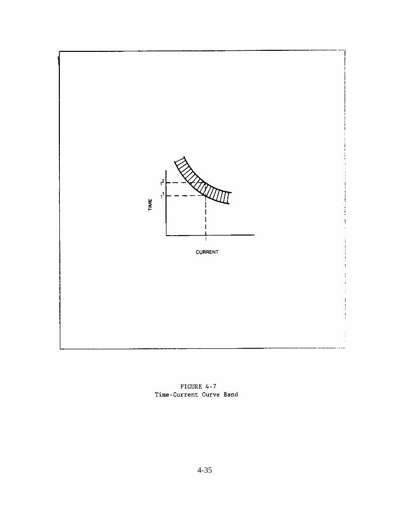
4-35
(a) Apparent power and voltage ratings, as well as the impedance and connections ofall transformers.
(b) Normal and emergency switching conditions.
(c) Nameplate ratings and subtransient reactance of all major motors and generators, aswell as transient reactances of synchronous motors and generators, plus synchronous reactancesof generators.
(d) Conductor sizes, types, and configurations, and type of insulating material.
(e) Current transformer ratios.
(f) Relay, direct-acting trip, and fuse ratings, characteristics, and ranges of adjustment.
(g) Cable lengths, particularly if an impedance diagram is not included.
4.7.7.2 Short-Circuit Currents. The second requirement for a coordination study is acomplete short-circuit current detail, as described earlier. The short-circuit current study shouldinclude maximum and minimum expected three-phase and ground fault duties, as well asavailable short-circuit current data from all sources.
4.7.7.3 Time-Current Characteristics. The third requirement for a coordination study isthe determination of time-current characteristics of all the devices under consideration.
4.7.7.4 Maximum Loading. The fourth requirement for a coordination study is thedetermination of expected maximum loading on any circuit considered. Any limiting devicessuch as utility settings on relays must be noted.
4.7.8 Plotting Procedures. The practice of using overlays for making coordination curvesremoves much of the tedious work necessary in making coordination studies. Once a specificcurrent scale has been selected, the proper multipliers for the various voltage levels considered inthe study are calculated. Protective device curves for the various devices are then plotted ongraph paper. Preferably, the curves are plotted progressively as each circuit is studied, startingwith the device furthest from the source. This procedure will show whether or not the proposedtime-current characteristic of each successive device coordinates with the one on its load side.Short circuit calculations can now be accomplished using computers. Use of computers providesincreased accuracy, shorter computation time, and accurate plotting. Several sophisticatedsoftware programs are now available for personal computers (PCs), as well as for mini andmainframe computers. With the inception of computers and associated software programs, shortcircuit studies can be performed in conjunction with voltage drop calculations. The mainadvantages realized in using this approach are system protection and system accommodation forfuture load growth, and the sizing of down line devices, accordingly.
4-36
CHAPTER 5. POWER SYSTEM INSTRUMENTS AND METERS.
5.1 INSTRUMENTATION AND METERING. This chapter discusses instruments and metersused in power distribution systems. Metering and instrumentation are essential for satisfactorypower system operation. Instruments and meters are needed for monitoring system operatingconditions and for allocating the costs of electrical energy purchase, generation, and distribution.
5.1.1 Basic Objectives. Instrumentation and metering assists operators in the operation of thepower systems. Information relative to the magnitude of loads, energy consumption, loadcharacteristics, load factor, power factor, voltage, and other parameters are required for properoperation. Certain checks are required on electric equipment, prior to placing it in service, toensure that the insulation is adequate for application of voltage and that the connections havebeen properly made. After equipment is in service, certain periodic checks are necessary toensure that the equipment remains in proper operating condition. Instruments and meters areused to perform these and many other important functions.
5.1.2 Definitions. The following two paragraphs broadly define power system instrumentsand meters.
5.1.2.1 Instruments. An instrument is defined as a device for measuring the value of thequantity under observation. Instruments may be either of the indicating or recording type.
5.1.2.2 Meters. An electric meter is generally thought of as a device that measures andrecords watts with respect to time or watt-hours. The term meter is also commonly used in ageneral sense, as a suffix, or as part of a compound word (such as voltmeter, frequency meter)even though these devices are, more correctly classified as instruments.
5.1.3 Alternating Current Measurements. Alternating current instruments and meters aredesigned to measure the root mean square values at the frequency specified and are calibrated fora pure sine wave. Any deviation in frequency or wave shape will result in a decrease in theaccuracy of the instrument or meter. A large variety of instruments and meters are available tomeasure alternating current system parameters. In most cases their current coils are rated 5 Aand their potential coils are rated 120 V. Instrument current and potential transformers are usedwhen the current and voltage of the circuit exceed the rating of the instruments.
5.1.3.1 Current Transformers. Current transformers isolate instrument circuits from theprimary circuits and reduce current through instruments to values within individual instrumentmeasuring element ratings. The current transformer ratio selected should be minimized, withoutexceeding rated current in the secondary winding. A ratio that will give a normal current readingat about one-half to three-quarter scale on the instrument should be used if possible.
5-1
On three-phase three-wire circuits, two transformers are sufficient for metering, although a thirdtransformer is sometimes used for checking the ratio of the others. On a three-phase four-wiregrounded system, three transformers are required. Usually the turns ratio of a current transformeris such that dangerously high potentials result when the secondary circuit is opened. A testswitch or current jack, therefore, is normally provided to short-circuit the transformer secondarywhile testing the instrument, or for using plug-in portable meters. The secondary circuits ofcurrent transformers are always grounded.
5.1.3.2 Potential Transformers. Potential transformers reduce voltages to values withinthe rating of instrument potential coils. Single-phase transformers are usually employed with twotransformers connected in open delta for three-phase three-wire circuits. For three-phasefour-wire systems, three transformers are required. Switches are provided in the potentialtransformer secondary circuit to disconnect the instrument for testing. Potential transformersecondaries are also grounded.
5.1.4 Direct Current Measurements. Direct current measurements employ either shunts orDC transformers to carry the main current to be measured.
5.1.4.1 Shunts. A shunt is made of metal with a low-temperature coefficient of resistanceand low thermoelectric effect with respect to copper. Strips of resistance metal are brazed intoheavy copper blocks which become both the terminals for the line and the leads to theinstrument. Ordinarily, the shunt must be calibrated with the leads attached. The direct currentammeter actually measures the millivolt drop across its shunt and is calibrated in terms of thecurrent rating of its associated shunt. Meters reading up to 50 A or less may have the shuntwithin the meter case. External shunts are available in ratings up to many thousands of amperes.
5.1.4.2 Direct Current Transformers. A direct current transformer is a form of magneticamplifier or saturable core reactor. Two double-circuit transformers are used, with one windingof each connected in the direct current circuit and the secondary windings excited by analternating voltage. As the direct current varies, it induces varying degrees of core saturation. Asthe transformer core saturation changes, so does the magnetic flux linkage of the AC secondarycircuit. An alternating current instrument senses the changes in the flux linkages of thesecondary circuit and is calibrated to read direct current amperes. This method has two definiteadvantages over the shunt method. The secondary circuit is isolated from the measured sourceand the user may add one or more instruments, relays, or other current-operated devices to thesecondary of the transformer. The lower cost and greater reliability of the direct currenttransformer provide a definite advantage over the shunt, for very high current values. Directcurrent transformers are especially useful where remote metering of large direct currents isinvolved, because calibrated leads are not required.
5.1.5 Transducers. Electrical quantities of alternating current systems can be measured byusing a transducer, that is referred to as a Hall generator and based on the Hall effect. The Hall
5-2

generator acts as a multiplying device, putting out a direct current millivolt signal proportional tothe product of the current and a magnetic field input. The magnetic field input may be developedfrom a current or a voltage source. The output signal may be used to operate a direct currentvoltmeter calibrated to the product units or as an input to telemetering or recording devices. TheHall generator principle has been applied to devices for the measurement of voltage, current,power, reactive power, power factor, and frequency. One advantage of the Hall generator type oftransducer is its small all-solid-state construction. Other advantages include its relatively highoutput signal level, a high operating speed, and the output the transducer inputs.
5.2 INSTRUMENTS. This section provides descriptions of the various instruments used tomonitor power system operating conditions.
5.2.1 Ammeters. Ammeters measure the current flowing in a circuit. An ammeter or itsassociated current transformer primary is connected in series with the circuit being measured.
5.2.2 Voltmeters. Voltmeters measure the potential difference between conductors orterminals. A voltmeter is connected directly, or through a potential transformer, across the pointsto be measured. For voltmeters operating on direct current circuits above 300 V, external seriesresistors are commonly required.
5.2.3 Wattmeters. A wattmeter measures the magnitude of the electric power being deliveredto a load or group of loads. To indicate the product of voltage and in-phase current, thewattmeter has both potential coils and current coils.
5.2.4 Varmeters. A varmeter measures reactive power. A varmeter operates as a wattmeterwith the current coils connected in series with the circuit and the voltage phase shifted 90electrical degrees from the voltage across the circuit. Varmeters usually have the zero point atthe center of the scale, since reactive power may be leading or lagging. The varmeter has anadvantage over a power factor meter in that the scale is linear, and small variations in reactivepower can be read. A power factor meter may be difficult to read near unity power factor.
5.2.5 Power Factor Meters. A power factor meter indicates the power factor of the load. It isa direct-reading instrument that will indicate the power factor of a three-phase load only if thevoltage and load are balanced on the three phases. The meter consists of both current and voltageelements, utilizing instrument transformers where necessary. The meter indicates unity powerfactor on scale center and lead or lag for any power factor other than unity. It is possible toobtain the average power factor over a definite period, like a day, week, or month, by use of thereadings of an integrating kilowatt-hour meter and a kilovar-hour meter.
5.2.6 Frequency Meters. The frequency of an alternating current power supply can bemeasured directly by frequency meters. The most commonly used type is the pointer-indicatingtype.
5-3
The pointer-indicating type frequency meter is connected directly across the line or the secondaryof one phase of a potential transformer. A frequency meter may have a scale range such as 55 to65 Hz or 58 to 62 Hz for use on a 60 Hz system, and the moving pointer indicates the exactvalue.
5.2.7 Portable Instruments. Most instruments are permanently mounted on switchboards, butmany can be obtained in portable forms. Portable instruments are useful for special tests or foraugmenting permanent instruments. Provisions are sometimes made on the secondaries ofinstrument transformers for connecting portable instruments into the circuit. Portable current andpotential transformers are available when the self-contained range of the portable instrument isnot sufficient for the values to be measured.
Examples of typical portable instruments are portable ammeters, voltmeters, and wattmeters. These may be of the indicating or recording type depending on the type of test or data required. A versatile alternating current portable instrument, sometimes called a circuit analyzer, isavailable to read current, voltage, and resistance. The circuit analyzer may operate on eitheralternating or direct current, therefore, providing flexible instrumentation for various conditions.
5.2.8 Recording Instruments. Most instruments available as direct-reading indicatinginstruments are also available as recording or curve-drawing instruments. A continuous recordof current, voltage, power, and frequency may be required for economic, statistical, andengineering studies, as well as for checking operator and machine performance. The record istraced automatically on either a strip or a circular chart by a pen fastened to the end of the pointerof the instrument. The chart is moved at a constant speed by a clock mechanism. Somerecording instruments have adjustable speeds for movement of the chart. Normal records areobtained at a speed consistent with chart-changing schedules, types, and load characteristics. Special tests may require a more rapid chart speed in order to obtain proper data. These specialtests may require more sophisticated equipment, such as magnetic tape recorders.
5.2.9 Miscellaneous Instruments
5.2.9.1 Temperature Indicator. Temperature indicating and temperature control devicesinclude liquid, gas, or saturated-vapor thermometers, resistance thermometers, bimetalthermometers, radiation pyrometers, and thermoelectric pyrometers. These devices may beobtained as indicating instruments or as recorders. They are used for measuring temperatures ofelectric windings, bearings, oil, air, and conductors. Some of them can be obtained with electriccontacts for use on an alarm device or relay circuit. Pyrometers are generally used for indicationand control of furnace temperatures.
5.2.9.2 Megohmmeter. A megohmmeter is an instrument for measuring the insulationresistance of electric cables, insulators, buses, motors, and other electric equipment. Themegohmmeter consists of either a hand- or motor-driven direct current generator and resistance
5-4
indicator. It has a maximum indication of 50,000 megohms to infinity and is available indifferent voltage ratings, usually 500, 1000, or 2500 V. Performance of an insulation resistancetest on electrical insulation (prior to placing equipment in service or during routine maintenance)will provide a good indication as to the condition of the insulation. Wet insulation can bedetected very readily. A high reading, however, does not necessarily mean that equipment canwithstand the rated potential since the instrument does not apply rated potential. Ahigh-potential test, in addition to the resistance test, may be desirable but not practicable. In lieuof a high-potential test, a dielectric-absorption test, using a megohmmeter, may be performed. Recording and plotting periodic resistance readings will show trends and may often predictinsulation failure.
5.2.9.3 Ground Ohmmeter. A ground ohmmeter measures the resistance to earth ofground electrodes. Calibration is usually zero to 500 ohms. Some types of ground ohmmetersalso include provision for measurement of soil resistance.
5.2.9.4 Low-Resistance Ohmmeter. Low-resistance ohmmeters are available for smallresistance measurements such as electric conductors, joints, contact surfaces, and electricwindings. The low-resistance ohmmeter is not considered a high-precision device, but it isuseful in field testing. Low-resistance ohmmeters contain a source of direct current and a meterto read the resistance in microhms.
5.2.9.5 Ground Detector. A ground detector indicates a ground path on an ungroundedsystem. Direct-reading types are available. An incandescent lamp ground detector connectedeither directly to low-voltage systems or to potential transformers on medium-voltage systems issometimes used. The voltage rating of the lamp is selected so that the lamp glows on the normalsystem. Whenever a ground fault occurs on one phase of the system, the lamp connected fromthat phase to ground will go out or dim and the other two lamps will glow brightly. With a faultof sufficiently low resistance on one phase, the lamp glow difference can be detected visually. A voltage relay and an alarm device could be installed to sound whenever a ground fault occurs.
5.2.9.6 Oscillograph. An oscillograph is an instrument for observing and recordingrapidly changing values of short duration, such as the waveform of alternating voltage, current, orpower. The oscillograph has many uses, such as determining transient characteristics of voltage,current, and other phenomena which occur too rapidly for measurement, by indicating meters. Frequencies of up to approximately 10,000 Hz can be measured.
(a) Most magnetic-type oscillographs consist of a galvanometer (which givesdeflections closely proportional to the instantaneous value of current or voltage), an opticalsystem (using a light beam from a mirror rather than usual pointers), and the recording device(film or light-sensitive material which can be moved rapidly). Multi-element oscillographs areavailable for recording several different values simultaneously, such as, three-phase current,voltage, and power.
5-5
(b) Direct-writing oscillographs record the phenomena or transients directly on a paperchart using an inking pen. Due to the pen inertia, this type of instrument has a limited frequencyrange in the order of 0.5-100 Hz.
5.2.10 Accuracy. The accuracy of an instrument is based on standard conditions at 25�C in anormal mounting position with no stray field (other than the earth's) and no DC ripple. The ACpower source should have a pure sine wave and normal frequency. Accuracy class is now statedas the limit expressed in percent of fiducial value (usually full scale value) at which errors willnot be exceeded under standard conditions.
Switchboard instruments are usually 1.0 percent class. Panel instruments (2-1/2 to 5-1/2 inchsizes) are usually 2.0 percent class, however, in special cases panel instruments may be 1.0percent. Smaller panel instruments may be as much as 5.0 percent; although some of thecheaper, but larger types, also fall into this category. Portable instruments have recognizedaccuracy classes of 0.25 percent, 0.5 percent, and 1.0 percent. These are the most common andpractical classes for general maintenance work. Manufacturers mark instrument dials with anumber (0.5 or 1.0) to denote their accuracy classification.
5.3 METERS. This section provides descriptions of the various meters used to monitor powersystem operation conditions.
5.3.1 Watt-hour Meters. Watt-hour meters measure the amount of electric energy used by aload. Alternating current watt-hour meters employ the induction-disk type of mechanism; thedisk revolves at a speed proportional to the rate at which energy is passing through the meter. The number of revolutions, through a gear train, is recorded on a dial in kilowatt-hours. Thewatt-hour meter may be used to calculate the power used by a load. Count the number ofrevolutions of the disk for any number of seconds and use this formula:
power (kilowatts) = 3600 x R x Kh ������������� 1000 x S
Where: Kh = the meter constant (marked on the meter disk or nameplate) R = the number of revolutions S = the number of seconds
If the power is being measured through instrument transformers external to the meter, the meterconstant must be multiplied by the instrument transformers ratios (Kh x PT ratio x CT ratio).
5-6

5.3.1.1 Instrument Transformers. Current and potential instrument transformers may beused with watt-hour meters. On three-phase three-wire circuits, two current-element meters areused. On four-wire circuits, three current-element meters are necessary.
5.3.1.2 Ratings. Watt-hour meters are rated according to voltage, current, and frequency. Transformer-rated meters are suitable for service at all voltage and current ratings when usedwith appropriate instrument transformers.
(a) The voltage rating for a particular application depends upon the feeder connection. For self-contained meters, applied on a three-phase three-wire system, the meter is rated atline-to-line voltage. For metering a load, served from a three-phase four-wire wye system, themeter is rated at line-to-neutral voltage. The standard voltage ratings are 120, 240, and 480 V.
(b) The following two standard curlent ratings are applicable to each meter:
o The class designation (CL) of a watt-hour meter denotes the maximum load range in amperes. The standard class ratings are 10 (for transformer-rated
meters), 100, and 200. o The test current rating (TA) of a meter corresponds to the value of current at
which the watt-hour meter is calibrated. Standard test currents and their relations to meter class are: CLIO - TA 2.5 A, CL100 - 15 A, and CL200 - 30 A.
(c) The standard frequency rating is 60 Hz.
5.3.2 Demand Meters. The maximum power demand during a specified period of time ismeasured by a demand meter. Both indicating and recording meters are available for thispurpose.
5.3.2.1 Curve-Drawing Wattmeters. Curve-drawing wattmeters, which record theload-time curve of the system, can be used to determine the maximum demand by averaging theload over the selected demand interval of time.
5.3.2.2 Integrating Demand Meters. Integrating demand meters totalize the energy usedover the demand interval and either record the average demand for each interval or, by means ofa maximum indicating pointer, indicate the maximum demand that has occurred since the meterwas last read and reset. The most common demand intervals used in commercial metering are 15minutes and 30 minutes.
5.3.2.3 Lagged Demand Meters. Lagged demand meters usually obtain their demandinterval by thermal time lag. Lagged demand usually indicates 90 percent of the maximum valueof a suddenly applied steady load by the end of the selected demand interval, and 99 percent atthe end of the succeeding interval.
5-7
5.3.2.4 Contact-Operated Demand Meters. Contactors can be attached to watt-hourmeters to transmit impulses at a rate proportional to the load. These impulses operate thedemand meter to drive a pointer or pen. The indicator is reset at the end of the demand intervalby a synchronous or mechanical clock. Contact-operated demand meters have the advantage ofeasier servicing than combined watt-hour meters and demand meters. Additionally, the demandsof several lines or loads can be combined through a totalizing relay to operate one demand meter,giving total demand. Phase-shifting transformers and scale plates are available to make themeters read the demand in kVA. The demand in kVA may be more useful in determining theactual load in terms of equipment rating.
5.3.2.5 Printing Demand Meter. Another type of contact-operated demand meter is theprinting demand meter which records the demand for each interval by printing it on a tapetogether with the time of day.
5.3.2.6 Magnetic Media Recording Meter. A variation of the printing demand meter is themagnetic media recording meter. Kilowatt-hour (kWH) pulses and time pulses are recorded onmagnetic media. The data can later be recovered directly by computer. The major advantage ofthis magnetic storage is the elimination of manual chart or tape reading and manualcomputations.
5.3.3 Metering outfits. Instrument transformers for outdoor primary metering installationsare available as packaged units. The packaged units are available for single-phase andthree-phase applications.
5-8

CHAPTER 6. POWER SYSTEM OPERATION.
6.1 POWER SYSTEM STRUCTURE. This chapter will discuss the structure, the procedures,and the various switchboards generally applicable to Power System Operating Centers.
6.1.1 Bulk Power System. A bulk power system consists of the generating sources, thetransmission system, and the distribution system. A broad description of each subsystem isprovided in the following subparagraphs.
6.1.1.1 Generating Sources. Generating sources consist mostly of synchronous generatorsdriven by steam, gas, or hydro turbines. Energy is delivered to the transmission system through astep-up transformer.
6.1.1.2 Transmission System. The transmission system consists of separate successivenetworks servicing the same geographical area. These networks operate at different voltages andare tied together at substations. The transmission network also serves to integrate neighboringpower systems with the underlying system through interconnections.
6.1.1.3 Distribution System. The distribution system is similar in structure to thetransmission system, however, each network covers a much smaller geographical area. Thedistribution system also provides service to individual customers, rather than providing service toother systems.
6.1.2 Power System Objectives. All power systems (utility, industrial, commercial, andresidential) have in common the function of providing electric energy safely, reliably, and aseconomically as possible. Correct voltage and frequency wave shape must be continuouslymaintained within permissible limits. A complex, but coordinated, control network is requiredto provide proper system operation.
6.1.3 Power Systems Control Network. The combination of multiple generating sources andseveral layers of transmission and distribution networks provide a high degree of systemredundancy. Superimposed on this physical structure is a control and automation system that ishighly distributed and is designed to provide redundancy in a manner similar to that provided bythe power system.
6.1.3.1 Control Centers. The hierarchy of control centers in the United States, indescending order from the national level to the local distribution areas, is as follows:
(a) The National Council coordinates regional centers. (b) The Regional Coordination Center coordinates power pools.
6-1

(c) The Power Pool Operating Center is the interconnection of power systems. (d) The Power System Operating Center monitors the transmission and distributioncenters and power plant operations.
6.2 CONTROL CENTER PROCEDURES. Complex power systems provide reliable electricservice at low cost with the aid of automatic control. These systems simultaneously track therandomly varying system load, optimize generation to minimize cost, and coordinate the actionof many independent control centers. The primary functions of the control center are to manageresources, monitor performance and reliability, and adjust control parameters to maintain thedesired quantity and quality of electrical supply.
6.2.1 Power System Parameters. Considerable information regarding the power system isneeded to logically perform the control objectives previously described. The following is ageneral listing of the conditions and facts that must be identified.
(a) Position (open or closed) of circuit breakers and switches in the power system.
(b) Power flow, active and reactive, from each generating station, in each tie-lineinterconnecting the system with neighboring systems, and at key points in important transmissioncircuits.
(c) Energy (kWH) from generating stations and tie-lines.
(d) Bus voltage at each generating station and essential substations.
(e) System frequency.
(f) System time error, in seconds, based on a particular standard of reference.
(g) Tap position of load-ratio-control transformers or step-voltage regulators at keypoints in the transmission system.
(h) Current load on cables and transformers at critical locations in the transmissionsystem.
The transmission of information between locations is generally accomplished by telemetering. The transmission mediums are wire circuits, carrier (current) equipment, and radio or microwave.
6.2.2 Control Functions. Centralized equipment, both central (master) and remote, enablesoperators to supervise and operate remotely located power system elements (supervisory controlequipment). Examples of the functions or apparatus controlled from central locations by meansof the supervisory control equipment are:
6-2
(a) Start-stop. (b) Change levels. (c) Switching. (d) Lines. (e) Capacitors. (f) Reactors. (g) Synchronous condensers. (h) Power plants. (i) Transformer LTC tap. (j) Voltage regulator position.
Supervisory control equipment is often combined in quantities at remote locations such assubstations or switchyards. Circuits and equipment are energized by operating circuit breakersand switches. For decision making, the operator also receives information concerning equipmentstate and electrical loading. The remote supervisory equipment combines the capability ofreceiving and executing commands and transmitting associated information to the centralsupervisory equipment. The centrally located supervisory equipment conversely incorporates thecapability of receiving information and sending the operator's commands to a number of remotesupervisory equipment. Operators, therefore, may observe and control remotely locatedelements of the power system using both remote and centrally located supervisory equipment.
6.2.3 Basic System Control Operations. The control objectives of a power system are relatedto the conditional state at which the system is operating. As the conditional state decreasesbelow an acceptable threshold, restorative measures are initiated. The control systemcontinuously maintains a balance between load and generation or demand and supply throughbasic operations.
6.2.3.1 Load and Frequency Control. The load and frequency control, of interconnectedgenerators, introduces relatively simple problems to systems having one or two generatingstations. The problems caused by load and frequency control become more difficult in largeinterconnected systems having many stations scattered over a wide area.
(a) In small single-station systems, the operator can readily adjust the governors of theprime movers to divide the load most economically between them. Guided by an accuratefrequency meter and an electric clock (rather than a standard clock), the operator is able toaccurately maintain the station frequency and time.
(b) In large systems, a central load dispatcher is necessary to assign loads to variousstations and units in accordance with a predetermined schedule. This schedule is modifiedoccasionally as the actual load differs from the predicted load or as emergencies arise owing toloss of generating units or tie lines. The load dispatching may be by telephone, remotetelemetering and signaling, or both. Load assignment to a particular station varies with the type
6-3
and function of the station and its relation to the system. Frequency control is sometimesassigned to one of the largest generating stations. Very large systems are sometimes divided intoload districts, each with its own load dispatcher, often with a central load-dispatching agency forgeneral supervision over the districts.
(c) Automatic load-frequency control is necessary for maintenance of good overallsystem operations, proper sharing of load between generating stations, suitable regulation oftie-feeder loading between systems, and maintenance of proper frequency and time control. Theproblem of control resolves itself into:
o The measurement of a quantity.
o Interpretation of the measurement in terms of deviation from a control point.
o The application of corrections to restore the measured quantity to its normal value. In some cases more than one measurement is required for proper operation of the control equipment.
Generator, station, and system loads are measured through the summation of variousthermal-converter millivolt outputs. Frequency is measured by a frequency-bridge typeinstrument. As this data is fed into a master controller, it is able to detect the need for more orless generation and to send impulses to the different stations calling for load increase orreduction. By the use of area requirement (proportional load control), the equipment is able tocall for changes at the several generating stations. In effect, they supply the load of theirrespective areas, thereby causing a minimum of power flow over tie feeders from one station toanother.
6.2.3.2 Reactive Power and Voltage Control. A generator basically controls two of thekey parameters in a power system: the amount of power being generated to meet frequencyspecifications and the amount of reactive power being supplied to meet voltage specifications. The amount of field current supplied to the generator's rotor winding controls the amount ofreactive power generated. Normally, a monitoring system senses the voltage and automaticallyadjusts the field current to the generator to maintain that voltage at some prescribed value. If thesupply for a generator's field current fails, or if a short circuit develops within the field winding,the generator's ability to control the voltage within a power system is lost. Its ability to continuesupplying electric power, therefore, is greatly reduced. When a generator in this condition isallowed to remain connected to the system, it will cause a severe local voltage depression. Thisforces the system to supply a flow of reactive power to the generator from other sources in orderto maintain generator excitation. In many cases, however, the generator will continue to supplyelectric power, even after it loses its excitation supply, by operating as an induction machine. Itis then functioning at a slightly higher speed than that corresponding to system frequency. Consequently, the iron in its rotor's solid forging may overheat. A loss-of-field or
6-4

loss-of-excitation relay usually disconnects the generator when it begins accepting excessivereactive power from the outside.
6.2.3.3 Automatic Load Shedding. System frequency is a sensitive measure ofdiscrepancy between load and generation. In the normal operating state, the generation isadequate to supply the existing load and no equipment will be overloaded. If the systembecomes overloaded and additional generation is not available, the frequency falls below 60 Hz. Control centers normally have equipment that will automatically disconnect blocks of load whenthe system frequency reaches prescribed values below 60 Hz.
6.2.4 Computer Control. Today most generation and load control systems are computerbased. The computer can be programmed to provide format changes, to make comparisonsbetween desired and actual data measurements, and to correct system operation. These processesare performed faster using a computer than they are performed by human or hard-wired logiccontrollers. The computer can also provide efficient entry, formatting, and storage of data. Computer control of generating and transmission stations can also greatly improve the security ofthe power systems. For example, the computer can:
(a) Improve the monitoring and display of information. (b) Be programmed to evaluate contingencies and to develop corrective procedures.
6.3 SWITCHBOARDS. This section provides a general discussion of power and controlswitchboards, supervisory control equipment, and the automatic control of devices in generatingstations and substations.
6.3.1 Power Switchboards. For small stations or substations, the main switching equipmentand buses may be mounted directly on or adjacent to the board. For larger stations, the switchingequipment and buses are always remotely located in separate buildings or enclosures, oroutdoors. In these cases, the main switching equipment and buses are generally identified as busstructures. Power switchboards are also identified as:
(a) Direct control. (b) Remote mechanical control. (c) Electrically operated.
This section describes the various types of switchboards available to provide different functions.
6.3.1.1 Direct Control. Direct control panel-type switchboards are generally used forsmall and medium-capacity installations where a complete installation of only a few panels isrequired. They are designed for control of incoming lines, generators, motor-generator sets,induction and synchronous motors, feeders, light and power supply, control-power supply, andbattery-charging equipment.
6-5
6.3.1.2 Live-Front. Live-front switchboards have the circuit breakers and switchesmounted directly on the front of the panels and are generally limited to 250 VDC and 600 VAC. These are seldom used in modern designs.
6.3.1.3 Dead-Front. Dead-front switchboards have the breakers and switches mounted onthe rear of the panels and are generally limited to a maximum of 600 VDC and 2,500 VAC. Alldesigns are operated from the front, providing safety to the operator. Some types are alsoequipped with interlocking features that prevent access to live parts.
6.3.1.4 Control-Power. Control-power switchboards are used in generating stations andsubstations to provide a separate source of energy for the control of electrically operatedapparatus. The voltages ordinarily used are 125 and 250 VDC. The switchboards generallyinclude control for a storage battery, one or two motor-generators, and the required number offeeder panels.
6.3.1.5 Medium-Voltage. Medium-voltage metal-clad switchboards for 15,000 V or less,consist of equipment housed in steel compartments completely assembled by the manufacturer. This type of switchboard design is generally used for light, power, and station auxiliary powersupply in large generating stations and industrial plants. It is also used extensively for ACsubstation switching. As all medium-voltage parts are enclosed, the equipment is interlocked toprevent mistakes in operation. All parts of the steel enclosure are grounded providing maximumsafety to the operator for this class of switchboard. The secondary wiring is shielded, andbarriers are provided between phases and between adjacent circuit breakers.
6.3.1.6 Electrically Operated. Electrically operated switchboards employ solenoid- ormotor-operated mechanisms, some with stored-energy-type designs for circuit breaker operation. These are, in general, controlled from a central point or control board. This arrangement allowsfor the location of the control board to be independent of the location of the power board. Complete isolation of the high-tension equipment has been made possible.
6.3.2 Control Boards. The control of large power circuits by electrically operated breakershas effected the replacement of the switchboard by the control board. Several types of controlboards are in general use. On these are mounted the necessary control switches, lights toindicate the positions of the breakers, indicating and recording instruments, and relays. Thearrangements of devices on the boards are simple and distinctive to aid the operator in avoidingconfusion and mistakes under normal and emergency conditions. The control and indicatingdevices of each main power circuit are clearly set off from those of other circuits. Theassembly of the panels and the selection of the type of panel depend entirely upon the size andtype of station and on local conditions.
6.3.2.1 Indicating Lamps. Indicating lamps are used to indicate breaker position; greenlights indicating open breakers and red lights indicating closed breakers. White lights are
6-6
sometimes included to be energized from potential transformers to indicate live circuits. Somestations include orange or another distinctive color to indicate that the circuit has trippedautomatically. Red and green lights are commonly wired so that they are energized through thetripping coil and circuit of the breaker to supervise the trip circuit. An opening in the trip-coilcircuit is then indicated by a dark lamp.
6.3.2.2 Mimic Bus. Mimic buses are frequently installed on the faces of control boards toaid operation, showing in miniature the bus and the circuit connections controlled by each controlswitch.
6.3.2.3 Auxiliary Circuits. Auxiliary circuits used on switchboards provide the following:
(a) The use of one instrument for several machines or circuits is made possible by thevoltmeter bus and switches on plugs.
(b) Current supply for instruments and relays.
(c) Control power supply for operation of circuit breakers and switches.
(d) Annunciator or alarm circuits.
(e) Potential supply for relays.
(f) Synchronizing circuits.
(g) Test supply.
6.3.2.4 Ground Detector. Ground detectors are desirable on ungrounded systems so thatimmediate steps may be taken to clear a ground before a second ground occurs. The occurrenceof a second ground, before the first has been cleared, could create a phase-to-phase short circuit.
6.3.3 Supervisory Control Equipment. Supervisory control equipment is often used toremotely control a number of devices from a distant location, using a minimum number ofcommunication channels. The basic approach is to select, at one time, a single operating pointand connect the control for that device to the communication channel to permit remote operation. Generally, only one device can be controlled at one time.
6.3.3.1 Functions. The functions normally performed by supervisory control include thefollowing:
(a) Opening and closing circuit breakers and disconnect switches from the masterstation.
6-7
(b) Operating transformer tap changers and phase-angle regulator tap changers. (c) The control of valves. (d) Transmission of set points.
The supervisory equipment not only provides control from the master station, but is used totransmit position indications and metering from the remote to the master station. Anothercommon function is the transmission of alarm conditions from the remote to the master station.
6.3.3.2 Old Systems. Until recently, most supervisory systems consisted of relay chains atthe master and remote stations that were operated by pulse codes to select the proper operatingpoint and then perform the control action. These systems use various pulse codes on either DCor audio-tone communication channels. Generally, the transmission speed is rather slow and issuitable for telegraph-grade channels.
6.3.3.3 New Systems. The latest supervisory system uses solid-state components ratherthan relays to generate and receive selection and operation codes. They usually operate overaudio-tone channels using frequency-shift-type equipment and are capable of very high operatingspeeds. These systems can be operated over any high-speed communications channel includingmicrowave, telephone, or power-line carrier. Bit rates of 1,000 bits per second or higher arecommon. This type of equipment often continuously scans the alarm and indication points. Telemetering is usually accomplished by converting from analog to digital form at the remotestation and transmitting in digital form, a code similar to that for control being employed. Manymodern installations display the telemetered quantities in digital form at the master station. Various control sequences and code-checking techniques are used to assure operation of thecorrect device and prevent false operation. By using modern equipment, a very high degree ofsecurity is possible.
6.3.4 Automatic Control. Automatic control is a combination of various devices, includingrelay operational amplifiers, magnetic amplifiers, and solid-state switches, which are used toautomatically operate devices in generating stations and substations without operatorintervention. Unattended substations are usually designed to operate automatically. Theautomatic controls normally provided in unattended stations include automatic circuitbreaker reclosers, transformer tap changers or voltage regulators (to control voltage), andcapacitor switches.
6.4 SAFETY AND ENVIRONMENTAL REQUIREMENTS. This section provides adiscussion of the safety practices, environmental regulations, and occupational safety and healthrequirements that apply to the operation and maintenance of electric power distribution systems. Safety and health standards are prescribed by OSHA (29 CFR 1910) and the National ElectricCode (ANSI/NFPA 70). OPNAVINST 5100.23B specifies program requirements andestablishes standards for the safety and health of Navy employees. Activity Safety Offices
6-8

maintain copies of these publications. Do not hesitate to ask for their assistance. Make sure thatproper protective equipment and devices are used, hazardous work is preplanned, safety andrescue equipment is readily available, tools and equipment are properly maintained, employeesare trained in CPR and rescue techniques, and alcohol is not consumed during the duty day or 8hours prior to the shift.
6.4.1 Safety Practices. Safety related work practices should be used to protect personnel frominjury while they are working on or near electric circuits and equipment. Personnel should betrained in the safety related work practices, safety procedures, and other personnel safetyrequirements that pertain to their respective job assignments. Personnel should not be permittedto work in an area where they are likely to encounter electrical hazards unless they have beentrained to recognize and avoid the electrical hazards to which they will be exposed. An electricalhazard is identified as a dangerous electrical condition. Examples of electrical hazards areexposed energized parts and unguarded electrical equipment which may become energizedunexpectedly. Specific work practices are required for work under three separate conditions, asoutlined in the following subparagraphs.
6.4.1.1 Work On or Near Deenergized Circuits and Equipment. When work to beperformed requires personnel to work on or near exposed circuit parts or equipment, whendanger of electrical shock; unexpected movement of equipment, or other electrical hazards, thecircuit parts and equipment that endanger the personnel should be deenergized, locked out,tagged out and tried out. This shall in accordance with established Lockout-Tagout-Tryoutprocedures. These Lockout-Tagout-Tryout procedures should include procedures forimplementation responsibility, training, and coordination with other procedures. They shouldalso contain detailed requirements for administration, deenergization of circuits and equipment,application of locks and tags, verification of deenergized condition, tryout, coordination duringshift changes, restoration of electric service, testing, and temporary operation. TheLockout-Tagout procedures should be appropriate for the voltage rating and complexity of theelectric circuits and equipment in the workplace. The procedure should also be appropriate forthe various personnel involved, and other conditions in the workplace that are likely to endangerpersonnel who work on or near deenergized circuits and equipment.
6.4.1.2 Work Near Exposed Circuit Parts (Energized or may Become Energized). Whereit is not feasible to deenergize and lock out or tag out electric circuits and equipment, personnelshould be permitted to work near exposed electric conductors and circuit parts provided that theappropriate work practices and safeguards are implemented to protect personnel from injury. Personnel should be instructed to consider all exposed conductors and circuit parts to beenergized and dangerous. Safety related work practices shall be used to prevent electric shock orother electrically induced injuries when work is performed in the proximity of exposed electricconductors or circuit parts that have not been deenergized and locked out or tagged out inaccordance with subparagraph 6.4.1.1. Such work practices should include the use of safeguardsto prevent personnel from contacting energized circuit parts directly with any part of their body
6-9

and indirectly with the use of conductive wearing apparel, conductive materials or equipment,conductive tools, or some other conductive object. These work practices should includeconsiderations such as employee alertness, illumination of the work space, wearing of conductiveapparel, likelihood of contact with conductive materials and equipment, use of insulated tools,use of protective shields, use of proper portable ladders, work in confined spaces (such asmanholes and vaults), work on overhead lines, and performance of housekeeping or janitorialduties.
6.4.1.3 Work on Electric Circuit Parts or Equipment (Has Not Been Deenergized andLocked or Tagged Out). Personnel should not be permitted to work on electric circuit parts orequipment that has not been deenergized, locked out and tagged out, unless they are qualified andtrained to use safe work practices on such circuit parts or equipment. Safety related workpractices should be used to prevent electric shock or other electrically induced injuries whenpersonnel work on electric conductors or equipment that has not been deenergized. Onlyqualified personnel, who have been trained to work safely on energized circuits, should bepermitted to work on conductors or circuit parts that have not been deenergized and locked out ortagged out in accordance with the procedures in subparagraph 6.4.1.1. The personnel, whenappropriate, must also be trained to use proper protective equipment (i.e., insulating shieldingmaterials and insulated tools). Only qualified personnel trained to work safely with testinstruments and equipment on energized circuits should be permitted to perform test work onelectric circuits or equipment where there is danger of injury due to accidental contact withenergized parts or improper use of the test instruments and equipment.
6.4.1.3.1 Qualified personnel are those individuals that the Utilities Superintendent andElectrical Foreman judge to have sufficient experience for an assigned task.
6.4.2 Environmental Regulations. The major environmental regulations in force in theU.S.A. are those enforced by the Environmental Protection Agency (EPA). The materials used inelectrical materials and equipment are very similar to those used in various other industries andin commercial products. The exception to this is Askarel, which is a polychlorinated biphenyl(PCB) that is strictly regulated under the Toxic Substances Control Act (TSCA). Askarel is ageneric term (also a trademark of the Monsanto Co.) for a group of synthetic, fire resistant,chlorinated aromatic hydrocarbons used as electrical insulating liquids. Askarels are nowprohibited for use in new electrical equipment, however, their use continues in existingequipment. Askarels were most often used as the insulating liquid in capacitors, as well as inindoor liquid-immersed transformers. The TSCA classifies capacitors and transformers intothree categories and regulates them accordingly: (1) Non-PCB equipment, containing less than50 parts per million (ppm) PCB, is not regulated by the TSCA; (2) PCB contaminatedequipment, containing from 50 to 500 ppm PCB, is regulated by the TSCA; and (3) PCBequipment, containing 500 ppm or more PCB, is regulated by the TSCA. The TSCA hasprohibited the use of askarels in existing electrical equipment in a few industries, such as in thefood processing and handling industry and in the livestock feed industry. Disposal of askarels is
6-10

also strictly regulated. Special disposal procedures must be followed in the cleanup of askarelspills or leaks and disposal can only be done at specific hazardous waste treatment sites ordumps. Disposal of the PCB equipment is regulated similarly. PCB equipment must be clearlyidentified with EPA approved labels and records must be kept for all PCB equipment. PCBcontaminated equipment does not have the record keeping requirements of PCB equipment. Spills of 50 ppm (or greater than 50 ppm) PCB contaminated liquids, however, still require thespecial cleanup procedures.
6.4.3 Occupational Safety and Health Requirements.
6.4.3.1 Safety Requirements. The existing portions of the act generally govern theinstallation of electrical systems and do not attempt to cover the operation and maintenance ofthe electrical systems. This latter area is at the present time the subject of hearings and testimonypursuant to an OSHA rule making proposal on electrical safety related work practices, which waspublished in the November 30, 1987 Federal Register. This proposal would:
(a) Add a new standard on electrical safety related work practices for general industry.
(b) Revise references to the OSHA electrical standards.
(c) Remove existing work practice requirements from other parts of the OSHA generalindustry standards. This will ensure that all general electrical safety related work practices wouldbe covered by the electrical safety standards proposed and remove an existing provision relatingto construction from the general industry standards.
The OSHA standards, both existing and proposed, are based on consensus industry standardssuch as the National Electrical Code (ANSI/NFPA 70) and Electrical Safety Requirements forEmployee Workplaces (NFPA 70E). As such, they should certainly serve as a guideline forNAVFAC to use in its operations. In accordance with ANSI C2 National Electrical Safety Codespecifically for Distribution System installation, maintenance and operation.
6.4.3.2 Health Requirements. Health requirements have received renewed attention due tothe May 23, 1988 effective date of the OSHA Hazardous Material Communication Standard. This OSHA standard requires all industries to advise their employees of the presence ofhazardous materials in the workplace. Warnings are required to be posted and HazardousMaterial Safety Data Sheets (MSDS) must be maintained and posted. Examples of materialsused in electrical systems include mineral oil (used for insulating liquids), various cleaningfluids, cable pulling compounds, greases used for lubricating motors, protective coatings, andpaints, etc.
6-11
CHAPTER 7. ELECTRICAL UTILIZATION SYSTEMS.
7.1 SYSTEM VOLTAGES. The most common utilization voltage in United States industrialfacilities is 480 V. Other voltage levels depend upon motor size, utility voltage available, totalload served, potential expansion requirements, voltage regulation, and cost. The system must becapable of providing power to all equipment within published voltage limits under all normaloperating conditions.
The preferred utilization voltage for industrial plants is 480Y/277 V. Small dry-type transformersare utilized to provide 480-208Y/120 V or 480-120/240 V service.
Some loads, particularly large motors above 200 horsepower (hp), can often be served moreeconomically at voltages above 600 V. When the plant primary voltage is suitable, these largeloads may be served directly at primary voltage. For example, motors over about 200 hp may beserved directly from 2400 V primary systems, motors over 250 hp from 4160 V systems, motorsover 1000 hp from 6900 V systems, and motors over 2000 hp from 13.8 kV systems. Largemotors, or a group of scattered motors, may be served directly from the medium-voltage primaryfeeders or through a transformer.
7.2 EQUIPMENT NAMEPLATE RATINGS AND NOMINAL SYSTEM VOLTAGES. Thissection provides a discussion on the requirements and usage of equipment nameplate ratings andthe effect of deviations in the nominal system voltage from these ratings.
7.2.1 Nameplate Ratings. Utilization equipment is defined as electric equipment which useselectric power by converting it into some other form of energy. Light, heat, or mechanicalmotion are a few examples of converted energy. Each component of the utilization equipmentrequires a nameplate. The nameplate must list the nominal supply voltage for which theequipment is designed. Most utilization equipment (except motors) carries a nameplate ratingwhich is the same as the voltage system on which it is to be used (e.g., equipment to be used on120 V systems is rated 120 V; equipment to be used on 208 V systems is rated 208 V, etc.).
7.2.1.1 Single-Phase Motors. Single-phase motors for use on 120 V systems have beenrated 115 V for many years. Single-phase motors for use on 208 V single-phase systems arerated 200 V, and for 240 V single-phase systems they are rated 230 V.
7.2.1.2 Three-Phase Motors. Prior to the late 1960s, low-voltage three-phase motors wererated 220 V for use on both 208 and 240 V systems; 440 V for use on 480 V systems; and 550 Vfor use on 600 V systems. Nameplate ratings for new motors are 200 V, 230 V, 460 V and 575V; for use on 208 V, 240 V, 480 V and 600 V systems, respectively.
7-1

7.2.2 Effect of Voltage Variations. When the voltage at the terminals of utilizationequipment deviates from the value listed on the nameplate of the equipment, the performanceand the operating life of the equipment is affected. The effect may be minor or seriousdepending on the characteristics of the equipment and the amount of the voltage deviation fromthe nameplate rating. Generally, performance conforms to the utilization voltage limits, but itmay vary for specific components of voltage-sensitive equipment. In addition, closer voltagecontrol may be required for precise operations.
7.2.2.1 Induction Motors. Motor voltages below the nameplate ratings result in reducedstarting torque, increased full-load temperature rise, and increased load current. Motor voltagesabove nameplate ratings result in increased torque, increased starting current, and decreasedpower factor. The increased starting torque will increase the accelerating forces on couplings anddriven equipment. Increased starting current causes greater voltage drop in the supply circuit andincreases the voltage dip on lamps and other equipment. In general, voltages slightly abovenameplate ratings have less detrimental effect on motor performance than voltages slightly belownameplate ratings.
7.2.2.2 Synchronous Motors. Synchronous motors are affected by variations in voltage inthe same manner as induction motors, except that their speed remains constant (unless thefrequency changes). Additionally, their maximum or pullout torque varies directly with theirvoltage, if the field voltage remains constant. If the field voltage varies with the line voltage, asin the case of a static rectifier source, then the maximum or pullout torque varies as the square ofthe voltage.
7.2.2.3 Incandescent Lamps. The light output and life of incandescent filament lamps iscritically affected by voltage. The light output decreases with lower voltages but the life of thelamp increases. The reverse is true for higher voltages.
7.2.2.4 Fluorescent Lamps. Fluorescent lamps, unlike incandescent lamps, operatesatisfactorily over a range of +/- 10 percent of the ballast nameplate voltage rating. Light outputvaries approximately in direct proportion to the applied voltage. Thus a one percent increase inapplied voltage will increase the light output by one percent and, conversely, a decrease of onepercent in the applied voltage will reduce the light output by one percent. The life of fluorescentlamps is affected less by voltage variation than that of incandescent lamps. The voltage-sensitivecomponent of the fluorescent fixture is the ballast, a small reactor or transformer which suppliesthe starting and operating voltages to the lamp and limits the lamp current to design values. These ballasts may overheat when subjected to above normal voltage and operating temperature.
7.2.2.5 High-Intensity-Discharge Lamps (Mercury, Sodium, and Metal Halide). Mercurylamps using the conventional unregulated ballast will have a 30 percent decrease in light outputfor a 10 percent decrease in terminal voltage. If a constant wattage ballast is used, the decreasein light output for a 10 percent decrease in terminal voltage will be about 2 percent. The
7-2

mercury arc will be extinguished at about 20 percent undervoltage. The lamp life is relatedinversely to the number of starts. If low-voltage conditions require repeated starting, the lamplife will, therefore, be reduced. Excessively high voltage raises the arc temperature which coulddamage the glass enclosure if the temperature approaches the glass softening point. Sodium andmetal halide lamps have similar characteristics to mercury lamps, although the starting andoperating voltages may be different.
7.2.2.6 Capacitors. The reactive power output of capacitors varies with the square of theimpressed voltage. A drop of 10 percent in the supply voltage, therefore, reduces the reactivepower output by 19 percent.
7.2.2.7 Solenoid-Operated Devices. The pull of alternating current solenoids variesapproximately as the square of the voltage. In general, solenoids are designed to operatesatisfactorily on 10 percent overvoltage and 15 percent undervoltage.
7.2.2.8 Solid-State Equipment. All solid-state devices are very sensitive to change involtage and temperatures with respect to time. All solid-state circuits, therefore, incorporateadequate regulation circuitry which then makes the devices very stable.
7.3 STREET LIGHTING SYSTEMS. For many years lighting service was powered by specialcircuits that could be energized only during periods when lighting was required. These specialcircuits usually had many lights connected in series. They, therefore, operated at a fairly highvoltage and low current and were operated manually or by time-clock-controlled switches. Modern circuits use photoelectric controls which have a high order of reliability at reasonablecost. Photoelectric controls make it feasible and economical to connect streetlight luminairesdirectly to area distribution. This eliminates the separate circuits and control systems.
7.3.1 Multiple-Circuits. Multiple lighting is used extensively today and is usually connecteddirectly to local low-voltage (120, 208, 240, or 277 V) distribution. The lights ordinarily arecontrolled by photocells. For special applications they may be operated continuously or may beswitched by time clocks, pilot wires, carrier-current signals, or other means.
Lamp units used for multiple street lighting originally were incandescent bulbs ranging in sizefrom 100 to 1,000 watts (W). Today there is a much broader range, including fluorescent andhigh-intensity discharge lamps (mercury vapor, high pressure sodium, and metal halide). Alllamps are available in a wide range of mountings designed to direct the light output in a varietyof patterns to match requirements, as well as in a choice of designs to suit the environment.
7.3.2 Series Street Lighting. Series street lighting is still extensively employed. Unlikegeneral distribution, it is powered by a variable-voltage constant-current system.
7-3
7.3.2.1 Constant-Current Transformers. Constant-current transformers are commonlyused to supply current, usually 6.6 or 20 A to the many lamps connected in series. Themoving-coil constant-current transformer is a single-phase device with inherently high leakagereactance. Movement of the coil varies this reactance automatically to maintain constant-currentoutput. The transformer is capable of regulating current within 1 percent for all loads within itsrating, at any supply voltage within 5 percent of normal, and with any ordinary variation infrequency and temperature. Full-load power factor is approximately 75 percent and three-fourthsload power factor is about 56 percent. Input kVA is substantially constant over the entire rangeof loads. In certain designs, capacitors improve the low power factor to a value near unity fornormal loads. The indoor or station type of constant-current transformer is supplied from thesubstation high-tension bus. Indoor ratings vary from 5 to 70 kW, with 30 kW and 60 kW beingthe most popular. The secondary winding of larger ratings is usually designed with two coils,and leads from each coil are cross-connected to supply two series circuits. The pole- andsubmersible-type constant-current transformers are built in sizes from 2 to 30 kW in oil-filledtanks, usually with capacitors. They are mounted in the immediate vicinity of the lamps theysupply, thus realizing economy in circuit construction. Distribution primaries supply theconstant-current transformers with single-phase power.
7.3.2.2 Series Circuits. Current in a series circuit passes directly, without transformation,through the lamps and circuit. Most circuits operate at 6.6 A. Circuits serving large lamps in theheart of a city often operate at 20 A. Series circuits are usually carried on the same crossarmswith primary wires in overhead distribution and in separate ducts or pipes in undergrounddistribution. In parkways, series-circuit cables are often buried. Individual lamps are providedwith series cutouts which automatically close the circuit when lamps are removed. A film cutoutdesigned to puncture at about 1,000 V is connected across terminals of each lamp; if the lampfilament breaks or burns out, the film cutout is punctured, the lamp is short-circuited, and thecircuit remains closed.
(a) Series circuits may be laid out on the parallel- or the open-loop plan. In theparallel-loop, outgoing and incoming wires of the circuit are carried along the same route; in theopen-loop plan, the circuit goes out along one street and returns by another. The parallel-looprequires greater mileage of wire to supply lamps in a given area than the open-loop method.
(b) Three disadvantages of the series circuit are:
o The necessity for insulating lamps, leads, fixtures, and circuits for full operating voltage to ground.
o The large exposure of circuit wire in which a break causes interruption to all lamps.
o The economic necessity of installing streetlighting wires on the same crossarm with primaries, causing wire congestion and exposing other distribution to
possible faulting if a streetlighting wire breaks.
7-4

CHAPTER 8. MANAGING THE OPERATION OF ELECTRICAL DISTRIBUTION SYSTEMS.
8.1 OPERATIONS OVERVIEW. The electrical distribution system performs the function oftransforming and distributing electric power throughout the facility of concern. The systemincludes the electrical equipment necessary to receive the electric power, transform the voltage tothe different utilization levels, and to control and distribute the electric power to the variouselectrical loads. By inference from the title of this chapter, the discussion is limited tospecifically exclude the operation of generation plants that may be on site.
This chapter is divided into three main sections. The first section discusses the day-to-dayoperation of the electrical distribution system, the second section discusses maintenance of theelectrical distribution system, and the third section discusses system planning studies. Theseareas require more than just day-to-day personnel supervision. There must be attentiondirected to operations, maintenance, and planning for the various short term and long term needsof the electrical distribution system.
8.2 OPERATIONS MANAGEMENT. Every electrical distribution system is unique. Thismanual, therefore, does not contain operating procedures detailing specific functions for aparticular distribution system. It is incumbent on the Operations Command Structure to have, inplace, sufficient operating procedures that are specific to the site and the system of concern. Thissection will discuss procedures and considerations that are believed necessary and of importancefor operating personnel to safely and efficiently operate electrical distribution systems. Thissection discusses the operation of an electrical system from the point of receipt of power at thesource or receiving station(s) to the points of load utilization. Additionally, this section willdiscuss various areas of consideration in the operation of the electrical distribution system.
8.2.1 Operating Procedures. Each electrical distribution system should have an operatingprocedures manual. For small simple systems, fed from utility services and consisting of onemain incoming service with a few radial feeders, this manual might consist of only a few pagesof simple instructions on the sequence of switching the main and feeder switching devices. Morecomplex systems, however, often require operating manuals consisting of hundreds of pages anddescribing the details of various portions of the system. The manual, regardless of the size, mustcontain up-to-date information of the equipment contained in the system. It should also reflectthe operating modes used, rather than those that might have been envisioned years previously fora system whose configuration and capabilities has been extensively modified.
The operating procedures manual should illustrate how to energize the entire system from thepoint of connection (to the power source) to the lowest utilization voltage level. It should havesufficient detail; including drawings, figures, and tables, so that reference to vendor manuals,equipment drawings, and other documents should not be necessary to operate the
8-1
distribution system. The manual should also describe the functions of the electrical distributionsystem and the individual equipment providing the operating capabilities of the variouscomponents. This should include the continuous, short time, and emergency ratings of alltransformers, switchgear, distribution panels, motor control centers, and feeder cables. It shouldrelate the operating modes of the electrical distribution system under various systemconfigurations and describe in detail the step-by-step procedures necessary to energize the entiresystem. It should detail the step-by-step procedures necessary to alter system configurations,describe the various alarm, trouble, fault detection and equipment shutdown systems provided. The operations manual should describe the analysis of various annunciator, alarm, protectiverelay, and equipment shutdown systems, including various checklists, as necessary, to indicatepossible causes of the trouble indication. It should, additionally, contain suggested courses ofaction, indication of the effect of the trouble on system operation, and the means of restoration ofservice to the affected area. The operating manual should also contain, as a minimum, one-linediagrams of the entire electrical distribution system that are up-to-date and contain eachequipment size and rating. For systems that can have multiple operating configurations, theone-line diagrams should indicate the normal operating position of the circuit switching devicesthat may be used to alter system operating configurations. This should include all bus tiebreakers and switches, circuit sectionalizing devices, incoming breakers from multiple sources, ifall sources are not energized simultaneously. This does not mean, however, that all radial feederbreakers must have their position shown, as it is understood that they must be closed for thesystem to function normally. When system equipment is replaced or modified, the drawingsmust be revised to reflect the changes made; the operating manual should be revised if the changecould affect the operating modes of the system.
8.2.2 Routine Operation. The normal operation of a well designed electrical distributionsystem should not involve day to day operating changes. If a generating plant is on site, theoperation of the distribution system is often integrated with the operation of the generating plant. The generating plant system operators, therefore, also serve as operating personnel for theelectrical distribution system. If there is no generating plant on site, the maintenance personnelof the electrical distribution system provide both maintenance and operation of the system.
A system is normally operated automatically by installed equipment. Even though thedistribution system can operate without intervention by personnel, collection of operating data bythe personnel can be beneficial to the routine operation of the system. The data can provideinformation for other personnel involved in the maintenance, design, or analysis of systemperformance. Routine readings should be kept of major bus operating voltages, feeder operatingcurrents, feeder kilowatt loads; including peak demands, feeder power factors, and energyconsumption (kilowatt-hours) for major sub-portions of the distribution system. Energyconsumption records may be required by accounting personnel to properly allocate costs ofelectric power to various subunits, however, this information is also useful for analysis of systemoperating factors. Use of modern electronic watt-hour meters, having advanced recordingfeatures on internal microcomputers, allows the data to be retrieved with personal computers by
8-2

the usage of modems. The software allows detailed analysis of system operations and productionof detailed reports showing almost all of the major parameters (voltage, current, power factor,demand load, kVAR load, and energy consumption) for individually configurable report formats. If such advanced recording devices are not installed, then the use of traditional chart recordersshould be considered for key operating parameters. The recorders should be used at least fortemporary periods to establish normal load cycles (time of daily, weekly, monthly, etc. peakloads), system voltages, power factors, and currents during these conditions. Recording thevoltages, power factors, and currents during light load conditions is also important to determinethe overall operating profile of the system.
Use of relatively inexpensive microcomputer load flow analysis programs, which have onlybecome available in the last few years, can be very useful in determining the optimum operatingconfigurations for the electrical distribution system. With the knowledge of peak and minimumload information and the use of the load flow analysis program, possible problems such as lowvoltage, overloaded conductors and equipment, and alternative operating configurations, duringsystem forced and planned outages, can be analyzed and the appropriate corrective actionplanned easily and quickly. In the past, these tools were not available to the operating personnel. Many catastrophic failures occurred as a result, due to the lack of adequate and timelyinformation.
8.2.3 System Disturbances or Outages. Even though the electrical distribution systemnormally operates for many days without any change in system configuration and without anydisturbances or outages to utilization equipment, there is always the chance of a fault or overloadthat will result in an electrical disturbance or outage. The term outage, as used here, is thecomplete absence of power at the point of use. The term disturbance is used for the temporarydeparture from normal of one or more of the parameters of electric power at the point of use. This includes such terms as sag, dip, surge, spike, impulse, noise, and phase shift. The moreusual disturbances involve line voltage impulses, noise, transients, steady-state voltage change,or a combination of these disturbances. Studies indicate that 90 percent of the disturbances areless than one second in duration and 80 to 85 percent involve only one phase of a three-phasesystem. Disturbances are usually classified by time duration, with disturbances lasting over oneminute usually being classified as an outage. The ranges of classification involve an overlap ofthe categories to some extent, although their use is not mandatory.
8.2.3.1 One Second to One Minute. These disturbances are usually attributed to severefaults on one or more phases and are manifested by 50 to 100 percent voltage loss on one or morephases. Often caused by lockout relays on circuit protective devices, this type of disturbanceresults in an outage to the system on the cleared side of the fault, however, on the power sourceside of the fault it is a disturbance. The cleared side of the fault refers to the system downstreamfrom the overcurrent or short-circuit protective device, which, when it operates, opens the circuitand thus de-energizes the downstream system and clears the fault. The power source side of thefault is the system upstream from the overcurrent or short-circuit protective device, and which,
8-3

after device operation, is still connected to the remainder of the power system and remainsenergized.
8.2.3.2 10 to 40 Cycles. These disturbances are classed as sags or surges due to theoperation of relatively slow speed switching devices, operation of tap changers on transformersand voltage regulators, and the starting of motors.
8.2.3.3 0 to 8 Cycles. These disturbances are classed as surges, or more commonly sags,due to the operation of fuses or high speed switching devices. Inrush currents result fromenergizing electrical equipment. A single-phase load on a multi-phase source may cause a surgeon the unloaded phases while causing a sag on the loaded phase.
8.2.3.4 0.001 to 1 Cycles. These disturbances are usually caused by surge arresteroperation, capacitor switching, and short duration faults.
8.2.3.5 Less Than 0.001 Cycle. These disturbances are generally classed as impulses; themost severe of these are caused by natural lightening, electrostatic discharge, and switching ofnearby loads.
The above paragraphs illustrate that the electrical distribution system may ride through mostdisturbances without change. The utilization equipment, however, may be unable to tolerate adisturbance. It may operate improperly, fail to operate, or operate in a such a way, that ifcontinued, may cause equipment failure or danger to personnel and operations. These factorsmust be taken into consideration at the time of the design and installation of the utilizationequipment. Although this problem is most often encountered with various types of electronicequipment, it can also effect mundane equipment such as fluorescent and sodium vapor lightfixtures. Since ideal power quality and continuity can seldom be obtained from the supplyingutility, the effects of power supply disturbances can be reduced to acceptable levels using thefollowing methods:
(a) Modify the design of the utilization equipment to be impervious to powerdisturbances and discontinuities.
(b) Modify the power distribution system to be compatible with the utilizationequipment.
(c) Modify both systems and equipment to meet a criterion that is realistic for both.
(d) Interpose a continuous electric supply system between the prime source and theutilization equipment. This will, however, act as a buffer to external sources of disturbances, butcould increase the magnitude of load induced disturbances.
8-4
Common solutions to the problem of electrical disturbances are filters, power conditioners, surgearresters, capacitors, solid-state motor starters, adjustable frequency motor drives, uninterruptiblepower supply systems, isolating transformers, and revisions to grounding systems. Sincedisturbances by their definition last less that one minute (most last less than one second) it isobvious that the distribution system must be designed and installed to operate automaticallywithout operator intervention to overcome the affects of disturbances. When outages occur, analarm or annunciator system should be used to provide operating or maintenance personnel anindication of the time of occurrence and location of the outage. This will allow promptimplementation of the restoration of electrical service to the affected area. The followingprocedures must be in place for the personnel to follow, so that a systematic method will be used:
(a) Report the problem and document the cause of the outage. (b) Change the system configuration as required to restore service. (c) Schedule repairs, if necessary. (d) Make the appropriate repairs or equipment replacements. (e) Restore the system to its normal operational configuration.
These personnel procedures should be performed in a timely and safe manner. When an outageoccurs on the electrical distribution system, a thorough investigation should be made todetermine the cause of the outage. The system configuration should be changed to removedamaged equipment from service. The system power should be restored after a check for safetyhas been made that determines that power can be restored. The safety considerations shouldinclude checking for possible damage to equipment, both upstream and downstream of thesuspected fault location, and the changing of certain switching devices to the off position, so thatthe unexpected return of power to certain equipment may not cause injury to personnel ordamage to equipment. These considerations should be a part of the operating procedures manualdiscussed in paragraph 8.2.1.
8.2.4 Power Quality. Power quality is usually measured by the amount of deviation from thenominal parameters that the steady-state power supply encounters. The usual parametersmeasured are the voltage and frequency, since the current is a function of the load level on thesystem. Measurements made on the system, or feeder voltage, usually include the magnitude. The phase angle might also be included when a significant unbalance is suspected due to largeloading on single phases of a multi-phase system. The frequency magnitude is also measured. Ifharmonics are causing a problem, then the various harmonic frequencies can be measured, aswell as the voltage of each harmonic. In order to perform the latter tests, sophisticated recordingdevices with fast response times and frequency spectrum analysis capabilities must be used. Ifthe purchase of equipment is not deemed economical, then it can be rented from one of severalsources. Additionally, if power disturbances are causing operating problems, then specialtransient recording devices must be used. These devices are used to record and monitor thesystem parameters over a set time period and provide sufficient data to determine the probablecause of the disturbances. This equipment is also costly; similar to harmonic analysis equipment,
8-5

the optimum solution may be to rent the equipment, as necessary. Specialized training is usuallyrequired to operate this test equipment.
System voltages normally operate within a steady-state range of 5 percent plus to 10 percentminus the nominal system value. This range corresponds to Voltage Range A (referenced inANSI C84.1, American National Standard Voltage Ratings for Electric Power Systems andEquipment (60 Hz)). The voltage range tolerance limits in ANSI C84.1 were established basedon the voltage tolerance limits of ANSI/NEMA MG-1, which establishes the voltage tolerancelimits of the standard induction motor. Since motors are the major component of utilizationequipment load on distribution systems, they were given primary consideration in theestablishment of the voltage standard. Use of the voltage range values in ANSI C84.1 can bedetermined for any system voltage because the numbers are established on a 120 V Base. Theproper voltage range for higher voltage systems, therefore, can be taken by multiplying thetransformation ratio of the system times the Base voltage range values. ANSI C84.1 specifies thevoltage at the two important points in the system. The first, is the maximum and minimum at thepoint of receipt from the power source. The second, is the minimum at the point of utilization. Italso provides recommended allocations for the voltage drop in the primary distribution system, inthe final distribution transformer, and in the final utilization voltage wiring from the lasttransformer to the utilization device. Consideration in developing the recommended rangesincluded the effects of high and low voltage on motor and lighting equipment lifetime, output,and starting characteristics.
8.2.4.1 Voltage Regulation. Voltage regulation, by definition, is the percentage change insecondary voltage from no-load to full-load conditions. The regulation is customarily specifiedat a specific power factor, as the power factor of the load affects the voltage regulation of thedevice or circuit. Voltage regulation cannot be improved by the use of the conventional no-loadtap changer on a transformer. The tap changer merely changes the transformer turns ratio, butdoes not significantly change the transformer impedance. The regulation (percent change fromno-load to full-load) will, therefore, not change. The operating voltage range will, however,change and affect the performance of the utilization equipment. As mentioned previously, loadflow studies should be performed and operating conditions (no-load, light-load, or full-load)examined to ensure that voltage tolerance ranges are not exceeded. If voltage tolerance rangesare exceeded, then one alternative is to adjust transformer taps to compensate for either highvoltage, at no-load or light-load conditions, or low voltage, at full-load conditions.
Capacitors of either switched or fixed configurations can also be used to correct the voltage rangeprofile of a distribution system. Often, for large complex systems, the use of switched capacitorsis the only realistic solution for a voltage range that is too wide. In this instance, capacitors areswitched off-line when the load is light, so that the voltage does not become too high. As theload increases, capacitors are switched on-line to prevent the voltage from becoming too low. For maximum benefit, capacitors should be located close to the load that is causing the problem,however, this is often not technically or economically feasible.
8-6

Synchronous motors can also be used to good advantage on large power systems if the 0.8 powerfactor design is purchased, rather than the less expensive unity power factor motor. The 0.8power factor synchronous motor can be used to improve voltage levels on its utilization bus inthe same manner as capacitors. Both devices act as a source of reactive power (VARs) to thesystem. Control of the operating voltage range can also be achieved by the use of transformerswith on-load tap changers and line regulators. Both devices use multi-tap devices, incombination with voltage sensing and control apparatus, to adjust the transformer ratio orregulator ratio by actively switching taps as the steady-state load changes. These devices areusually used by utilities in the primary distribution system and provide the final distributioncircuits with a voltage range within the Range A limits of ANSI C84.1. Unless the sitedistribution system is unusually large and complex, and the daily load fluctuations quite large,these devices are not applied to electrical distribution systems on facilities.
8.2.4.2 Power Factor Control. Power factor can be controlled using the same methods asthose used for controlling the voltage. Capacitors and synchronous motors can be switched oradjusted (either manually or automatically) to achieve a desired power factor. A high powerfactor (one close to unity or 100 percent) is generally desirable. When the various feeder andutilization circuits are operated at a high power factor, voltage drops and losses are minimizedthroughout the system. This is one way to achieve more load handling capability. There is moreequipment capacity available for real loads, if the reactive (kVAR) portion of the load is reduced,since most system devices are current sensitive. Often distribution systems are found operatingat power factors in the 70 percent range. If the power factor can be increased to the 90 - 95percent range, then the operating load on the equipment can be increased by 25 - 35 percent. Itis, however, frequently undesirable to operate the distribution system in the leading power factorrange. Operating the system with a leading power factor can possibly cause unstable transients. Since most loads are inductive in nature, it is usually difficult to get the distribution systempower factor into the high 90 percent range. It is even more difficult to achieve unity powerfactor.
Improved power factor control can release equipment for surplus use or make availableadditional load capacity with no change in the system configuration. The cost is usually nominal,especially when compared to the cost of new transformation equipment, switchgear equipment,and larger sized cables.
8.2.4.3 Harmonics. Harmonics on the distribution system is an increasing problemresulting from the growing use of solid-state switching devices in equipment, such as adjustablefrequency drives, rectifier power supplies, high frequency power supplies, uninterruptible powersystems, and arc discharge lamps. ANSI/IEEE 519, Guide for Harmonic Control and ReactiveCompensation of Static Power Converters, contains guidelines on input power sources for themaximum harmonic content total not to exceed 5 percent and the maximum for any oneharmonic not to exceed 3 percent of the fundamental frequency. Harmonic distortion iscalculated by using the square root of the sum of the squares of each of the harmonic amplitudes
8-7

(expressed as a percentage of the fundamental). Various means, usually filters, inductors,or capacitors, are used to reduce the effect of harmonics caused by loads on the system and onother loads.
8.2.4.4 Frequency. The system frequency regulation is generally determined by theserving utility. Most utilization equipment will operate satisfactorily over a frequency range of+/- 5 percent, however, most electronic equipment requires a tighter range of +/- 0.5 to 1 percent. This degree of frequency regulation is easily achieved by the use of utility grids in the continentalUnited States. Systems fed from isolated generation sources or those located in certain foreigncountries may experience frequency variations outside the range required by electronicequipment. These conditions may then require special static power supplies for such sensitiveelectronic equipment.
8.2.4.5 Voltage Unbalance. Voltage unbalance on multi-phase systems is usually limitedto a maximum of 3 percent. Unequal distribution of single-phase loads will increase the amountof voltage unbalance. Whenever possible, effort should be made to distribute the load evenlybetween the phases. Excessive phase voltage unbalance can cause excessive heating tothree-phase devices such as motors. Additionally, high ripple may be observed in somethree-phase AC/DC power supplies if the voltage unbalance is too high.
8.2.5 Operational Improvements. System configurations should be designed and installedwith provisions for future expansion, or possible changes in the system configuration, andimprovements to the system equipment. Operational improvements may be required resultingfrom increased load on the system or the addition of a different type of utilization equipment(which may require a different voltage or frequency to operate properly or a better quality supplythan that available). In these situations, the system must carry more load than originallyanticipated in the design. Increasing the distribution voltage(s) and increasing transformercapacity by the addition of cooling fans are two methods used on existing equipment to modifyand successfully fulfill the new load requirements. The improvement in system power factormay release additional system capacity for utilization to serve new loads, rather than beingwasted on the reactive power requirements of the existing system configuration.
8.2.5.1 Increasing System Distribution Voltage. This technique is often used on overheadpole line type distribution systems to increase system capacity. The system must havetransformers that are capable of operating at the new voltage. This method, therefore, is usuallylimited to systems consisting of many single-phase transformers operating in three-phase bankswhich can be reconnected on their primary side from delta to wye without change to thetransformer's operating voltage. The system voltage is generally increased by a factor of thesquare root of three (e.g., from 2400 V to 4160 V), the transformers are reconnected, and the newload is added onto the line at new transformer locations. of course, the existing transformerscannot carry additional load, but the individual distribution circuit's load capacity has increasedby the square root of three, or 1.732. If excessive voltage drop is a problem, then the same
8-8

solution can result in better voltage regulation at the end of heavily loaded circuits, as the loadcurrent of an existing load is reduced by the same factor. Load losses vary as the square of thevoltage, so an increase.in the operating voltage in the example by a factor of 1.732 will result inreduced losses by a factor of three. This method cannot be used if the distribution equipment,such as the cable, switchgear, or transformers are not rated for the increased voltage. On moremodern systems (consisting of three-phase transformers, underground cable, and metal-cladswitchgear), the equipment is usually operated at or near its design voltage ratings. A simpleincrease of system voltage, therefore, cannot be used to increase system capacity. In these cases,the practical solution is often to superimpose a new higher voltage distribution system on top ofthe existing system, and to serve the old loads from transformer substations. These substationsshould convert the supply voltage from the new system distribution voltage to the old one. Forexample, a newer 13.8 kV distribution system might be superimposed over an older 4.16 kVsystem, with several 13.8 kV to 4.16 kV substations installed to serve the old portion of thedistribution system. All new loads, however, would be fed by the 13.8 kV distribution systemwith direct transformation to the utilization voltage (e.g., 13.8 kV to 480 V).
8.2.5.2 Installation of Transformer Fans. When the load increases to, or above, thetransformer capacity at an existing substation, fans are often used to increase the transformer loadhandling capacity by a factor of 15 to 25 percent (depending upon the size of the transformer). The transformer bushings, primary and secondary load cables, switchgear or fuses, and otherfactors must also be investigated to assure that there are no other weak links in the system thatmay prevent full capacity utilization of the transformer's inherent capability. This should beincluded as part of the design criteria of the initial installation of the transformer equipment. The primary and secondary cables, bushings, and primary and secondary switchgear should all besized to provide greater load carrying capability than the transformer. Then, as the need arises,the transformer capacity can be increased relatively inexpensively by the addition of fans. Theother devices, such as bushings, cables, and switchgear cannot be inexpensively changed toachieve the same capacity increase, therefore, this capability should be provided upon initialinstallation.
8.3 MAINTENANCE MANAGEMENT. Every distribution system is unique in itsconfiguration, load, and types of installed equipment. This section provides general guidelinesregarding the requirements of a proper Electrical Distribution System Maintenance Program. Inboth the long term and in the day-to-day operation of the system, maintenance must be performedin order to preserve a reliable source of electric power. Often, however, it appears that anelectrical system requires no maintenance.
ANSI/NFPA 7OB-1987, Recommended Practice for Electrical Equipment Maintenance, is apremier source of information for all levels of personnel involved with the electrical distributionsystem. This document defines an Electrical Preventive Maintenance (EPM) program that isintended to reduce the hazard to life and property that can result from failure or malfunction
8-9

of electrical systems and equipment. It explains the benefits that can be derived from a welladministered EPM program and explains the function, requirements and, economicconsiderations that can be used to establish such a program. This section discusses these factors,but not in such detail as is provided in ANSI/NFPA 70B.
8.3.1 Need for an EPM Program. The need for an EPM Program, of electrical equipment, isnot apparent. The deterioration of electrical equipment occurs at a normal rate, however,equipment failure is not inevitable. As soon as new equipment is installed the process ofdeterioration begins. Unchecked, the deterioration process can cause malfunction or an electricalfailure. Deterioration can be accelerated by factors such as a hostile environment, overload, orsevere duty cycle. An effective EPM Program identifies these factors and provides measures forcoping with them. In addition to deterioration, there are other causes of equipment failure thatmay be detected and corrected through EPM. Included in these causes are load changes oradditions, circuit alterations, improperly set or selected protective devices, and changing voltageconditions. Without an EPM program, management assumes a much greater risk of a seriouselectrical failure and its consequences. A well planned EPM program will reduce accidents, savelives, and minimize costly breakdowns and unplanned shutdowns. Impending troubles can beidentified and solutions applied before they become major problems requiring more expensiveand time consuming solutions.
8.3.2 Benefits of an EPM Program. An effective EPM program provides both direct andindirect benefits. Direct benefits are generally measurable economic benefits derived from thereduced cost of repairs and reduced equipment downtime. Indirect benefits are less measurable,but very real, benefits. Benefits that are difficult to measure include safety, improved personnelmorale, better workmanship, improved productivity, reduced interruption of production, andimproved insurance considerations. To understand how personnel and equipment safety areserved by an EPM program, the mechanics of the program (i.e., the inspection, testing, and repairprocedures) should be understood. Improved morale will come from personnel awareness ofmanagement effort to promote safety by reducing the likelihood of electrical injuries, fatalities,electrical explosions, and fires. While the benefits resulting from improved safety are oftendifficult to measure, direct and measurable economic benefits can be documented by equipmentrepair cost and equipment downtime records after an EPM program has been placed in operation.
In many cases, the investment in EPM is small compared to the cost of equipment repair andproduction losses associated with an unexpected equipment shutdown. Insurance statisticsdocument the high cost of inadequate electrical maintenance. A study compiled by the FactoryMutual Insurance Group showed that in a two year study period one-half of the losses associatedwith electrical equipment failures could have been prevented with an effective EPM program. Several case histories have been documented relating preventable electrical equipment failurethat resulted from the lack of a maintenance program. Among them included a transformerfailure and fire that was caused by transformer insulating oil contamination. The transformeroil had not been tested in several years. The cost of the repairs alone would have paid for the
8-10

EPM program, not including the lost production value while the facility was without power. Another case documents a main service switchgear fire caused by fouling from dirt, gummydeposits, and iron filings. The switchgear damage alone was over $100,000, which would havepaid for the EPM program for many years. Another case documents the failure of a large singlemotor; causing the entire plant to shutdown for 12 days, as the motor was vital to the plantprocess. The failure was caused by dust clogged cooling ducts. An EPM inspection would havedetected the clogged ducts and prevented the failure and associated plant shutdown.
8.3.3 Ingredients of an Effective EPM Program. An effective EPM program is one thatenhances safety and also reduces equipment failure to a minimum (consistent with goodeconomic judgment). The basic requirements of the program include personnel qualified to carryout the program and regularly scheduled inspection, testing, and servicing of electricalequipment. Equally important to the success of the program is the application of soundjudgement in the evaluating and interpreting of inspection and test results and the keeping ofconcise, but complete records. The following factors should be considered when planning theEPM program:
o Personnel Safety. o Equipment Loss. o Production Economics.
The essential ingredients of a successful EPM program are:
o Responsible and Qualified Personnel. o Survey and Analysis of Electrical Equipment and Systems to Determine Maintenance
Requirements and Priorities. o Programmed Routine Inspections and Tests. o Accurate Analysis of Inspection and Test Reports so that Proper Corrective Action Can
Be Programmed. o Performance of Necessary Work. o Complete and Concise Records.
Additionally, the following must also be considered in establishing and maintaining an effectiveEPM program:
o Design of Equipment for Ease of Maintenance. o Training Programs for Technical Skills and Safety. o Use of Independent Companies for Specialized Services. o Proper Tools and Instruments.
8.3.4 Planning and Developing the EPM Program. The purpose of an effective EPM programis to reduce the hazard to life and property that can result from failure or malfunction of the
8-11

electrical system or equipment. There are four basic steps to implement the planning anddevelopment of an EPM program:
(a) Compilation of a listing of all plant equipment and systems (survey).
(b) Determination of the equipment and/or systems that are most critical and mostimportant.
(c) Development of a scheduling system for maintaining the timeliness of the project.
(d) Development of methods and procedures for each phase of work, or contracting forspecialized services required.
8.3.4.1 Maintenance Supervisor. The maintenance supervisor tasked with the planningand development of the EPM Program must be qualified both technically and administratively toeffectively perform in this position. The maintenance supervisor should have open lines ofcommunication to those personnel responsible for system and equipment design. Improperdesign, improper construction methods, and misapplication of hardware are a few of theproblems traced to an unsafe installation, or one requiring excessive maintenance. Themaintenance supervisor should be made aware of any deficiencies.
8.3.4.2 Maintenance Work Center. The maintenance work center must be properlyequipped and conveniently located. It should contain the inspection and testing procedures forthat area, copies of previous reports, single-line diagrams, schematic,diagrams, records ofcomplete nameplate data, vendors' catalogs, plants stores catalogs, and supplies of report forms. There should be adequate storage facilities for tools and test equipment required by themaintenance group.
8.3.4.3 Survey of Electrical System. This survey may be defined as the collection andevaluation of accurate data regarding the plant electrical system to be utilized as an informationaltool necessary for the development of an EPM program. The data collection step consists ofthree segments:
o Organizing the survey. o Setting priorities for each segment of the survey. o Assembly of all documentation.
The availability of up-to-date, accurate, and complete diagrams is the foundation of a successfulEPM program. An EPM program cannot operate without this data and its importance cannot beoveremphasized. The following documents are most often required:
(a) Single-line diagrams, showing circuitry down to the major utilization equipment.
8-12

(b) Short-circuit and coordination studies, which should be updated to reflect changesin: supply capacity, transformer size or impedance, conductor size, operating conditions andadditions of motors, and most importantly, changes to any protective devices or settings.
(c) Circuit routing diagrams or raceway layouts.
(d) Plot plans or equipment location plans.
(e) Schematic diagrams or elementary wiring diagrams.
(f) Connection wiring diagrams.
System diagrams are generally needed to complete the data being assembled. For a largebuilding complex, system diagrams for the lighting, ventilation, heating and air conditioning, andcontrol and monitoring systems are examples of system diagrams that may be required. Section4, System Planning Studies, provides a more thorough discussion of the collection and evaluationof electrical system data.
8.3.4.4 Emergency Procedures. The survey process also includes the acquisition orpreparation of emergency procedures. Emergency procedures should list, step by step, the actionto be taken in the event of an emergency. These should include procedures for the safe shutdownor start-up of equipment and systems. Optimum use of these procedures is made when they arebound for quick reference and located in the area of the equipment or systems. Also included inthe survey process, are the acquisition and maintenance procedures for proper test andmaintenance of equipment. The use of well maintained safety equipment is essential and shouldbe mandatory when working on or near live electrical equipment. Portable lighting is oftennecessary, particularly in emergency situations involving the plant electrical supply. Portablemeters and instruments are necessary for testing and troubleshooting, especially on circuits of600 V or less. The size of the plant, the nature of its operations, and the extent of themaintenance and repair program are all factors that determine the frequency and use of test andmaintenance equipment. Specialized equipment may often be rented or shared between nearbyfacilities.
8.3.4.5 Identification of Critical Equipment. Equipment is considered critical if its failureto operate normally and under complete control will cause a serious threat to personnel, property,or the product. Electrical power (i.e., process steam, air, water, etc.) may be essential to theoperation of a machine, however, unless the loss of one or more of these supplies causes themachine to become hazardous to personnel, property, or product, the machine may not beconsidered critical. The combined knowledge and experience of several people may be needed todetermine the criticality of a machine. An entire system may be critical by its very nature. Examples of critical systems are:
8-13
(a) Emergency lighting. (b) Emergency power. (c) Fire alarm systems. (d) Fire pumps. (e) Certain communication systems.
There are also parts of a system that are critical because of the function of the utilizationequipment and its associated hardware. An example of this is the safety combustion controls ona large boiler, whose failure may cause a serious explosion. Parts of the electrical system, suchas overcurrent devices or automatic transfer switches, are critical, because they reduce thewidespread effect of a fault in the electrical equipment. Alarm and shutdown systems are oftencritical, because they monitor the process and automatically take action to prevent a catastropheand alert operating personnel to dangerous or out-of-control conditions.
8.3.4.6 Scheduling. The proper scheduling of routine inspections and tests is the core ofan effective EPM program. They will determine the condition of electrical equipment, allowdetermination of what maintenance is required, and verify that equipment will continue tofunction until the next scheduled maintenance period. Factors that need consideration in thepreparation of a proper schedule are:
(a) Atmosphere or environment that the electrical equipment is located in (i.e., aircontaminant content, moisture, dust, hazardous vapors, chemicals, exposure to high ambienttemperatures and humidity.
(b) Load conditions (i.e., continuous-, intermittent-, periodic-, varying-, or short-timeduty cycles, running time, number of starts, operating overloaded.
(c) History of equipment, which is used to develop repair cost trends, items replaced,design changes or modifications, significant trouble or failure patterns, and the stocking ofreplacements.
(d) Inspection frequency, as determined by equipment criticality, manufacturers'servicing recommendations, operating duty, environmental severity, history or lack of priortrouble.
8.3.4.7 Methods and Procedures. Methods and procedures for an effective EPM programmust include not only the individual components of the electrical system, but the connectionsbetween those components. Neglecting the system's interconnections and operation together cancause unanticipated problems to occur. Although the manufacturer may have provided testingand calibrating procedures documentation for individual components, the application is oftenunique; therefore system peculiar inspection and testing procedures should be developed. Thesystem procedures should contain:
8-14

(a) Various required forms for use in the plant and in the field.
(b) A procedure for each piece of equipment; detailing the special tools, materials andequipment necessary; an estimate of the time to perform the work, references to appropriatetechnical manuals, record of previous work performed, items of special attention, precautions,unusual incidents, etc.
(c) Safety procedures to be followed, special test equipment required, protectiveequipment and barriers to be used, lockout/tagout/tryout procedure to be used.
(d) Implementation of actual plant inspection schedule, based on equipment scheduledinspection frequencies, personnel availability, availability of spare equipment, shutdownspermitted by operating personnel, anticipated time to perform inspections and tests, availabilityof replacement parts and special test equipment.
(e) Maintenance of records to evaluate results (i.e., inspection schedules, work orderlogs, unusual event logs, cost reports, and analysis of test results).
(f) Emergency procedures, including training in the emergency situations most likely tooccur, and periodic drills.
8.4 SYSTEM PLANNING STUDIES. This section discusses six system planning studies thatshould be conducted periodically. Performed regularly, the studies provide an organized way totrack key system characteristics, such as, power factor, annual usage, peak demand, energylosses, voltage and current profiles, and load factor. Tracking these characteristics helps thesystem engineer to improve system performance, minimize downtime, and manage systemexpansion. The studies should be performed simultaneously to ensure data consistency.
Each study is prepared on a load projection basis using an econometric forecasting method thatutilizes acquired electrical system historical data. The following studies will be discussed:
(a) Power Requirement Study. (b) Long Range System Planning. (c) Short Range System Planning. (d) Coordination Study. (e) Economic Conductor Analysis. (f) Power Factor Correction.
8.4.1 Objectives. The objectives of these studies are to improve system performance andreduce operating costs. The performance of the studies will provide information to ensure anadequate supply of power and continuous service. Preparation of the studies is discussed in thefollowing paragraphs.
8-15

8.4.2 Power Requirement Study. Data from the power requirement study providesinformation to forecast load growth. The following historical data is collected:
(a) Total peak demand. (b) Total annual demand. (c) Total annual energy used. (d) Purchases for a given period of time (at least five years).
Projecting these values on a graph gives an indication of future demand. The power requirementstudy will also show the annual losses and load factors for both past and future years.
8.4.3 Long Range System Planning. Long range planning studies provide an outline forsystem growth and information for short term planning of system improvements. It is essential toprovide the economical development of a system, assuring adequate service at the lowest cost. Long range planning is best provided using a map of the system that indicates the existingfacilities (with their associated loads) and future construction. A study of the map will help thesystem engineer ensure that changes to lines or substations will not effect the overall plan ofdevelopment.
8.4.3.1 Summary of Long Range System Planning. Long range system planning must becontinuous, due to changing conditions. The planning procedure must, consequently, makeprovisions for updating the plan. It must also provide a viable approach for implementing theplan into action. Maintaining the plan (map) is a continual process consisting of the followingsteps:
(a) Review the Base Master Plan annually. The Base Master Plan is a comprehensivestudy of the many planning factors (i.e.; electrical requirements, local industry, geology, railroutes, population growth, etc.) involved in the facility construction or modification of a navalactivity. The Shore Station Development Map, based on this study, is a graphicalrepresentation of the current and planned facilities. The map should be reviewed annually andprior to the design of new facilities. The map should also be updated, as necessary.
(b) Review the data on the existing system for accuracy and completeness. An analysisof the existing system is made to furnish the engineer with a foundation upon which to base thelong range plan. This analysis should include a review of the condition of the existing system.
(c) Prepare contingency plans for possible, but uncertain, future expansion. Thisrequires research of load levels with the capacity to support future expansion of the system.
(d) Select the most logical of the contingency plans when system changes are required. An examination of the contingency plans serves to determine the most sensible and economicalmethod for transition from the existing system to the long range system.
8-16

(e) Review the contingency plans annually, in light of changing conditions. Update theplan (map), as necessary.
(f) Prepare construction work plans, providing a construction program for theinstallation of needed facilities, two years in advance. This program will be used for thepreparation of detailed construction plans and specifications.
8.4.3.2 Details of Long Range System Planning. The following is required for detailedplanning:
(a) Up-to-date system map.
(b) Location of all major concentration loads.
(c) Results of voltage and current investigations.
(d) All pertinent data relative to existing and future loads.
(e) Power requirements study.
(f) Latest outage summary.
(g) Present transmission facilities.
(h) Availability of future power.
The first step is to analyze the existing system for system capacity relative to existing load andsystem performance. This includes voltage levels, current balance, service reliability, energylosses, and operating expenses. The analysis will be useful in identifying the weaknesses andstrengths of the existing system.
The second step is to project the long range load levels using an econometric forecasting method(graphing load versus time) with at least five years of historical data. The forecasting will helpestablish the growth pattern for the entire system and also the various segments of the system.
Having established and identified the growth areas, the third step is to impose the projected loadgrowths on the existing system to see if it will accommodate the growth. This step will indicateany required changes. The possible changes, that may be required, are listed below.
(a) Increase existing substation capacity.
(b) Add new substations to the system and analyze the existing transmission grid.
8-17

(c) Increase distribution line capacity.
(d) Add more distribution feeders from the existing substation.
(e) Analyze the system at different distribution voltage levels, thereby, adding fewersubstations at higher voltage and more at lower voltages.
To achieve orderly growth over the next twenty years, and after establishing a long range loaddesign, the next feasible step is to develop the load levels for the intermediate periods (i.e., loadlevels between present and long range load levels). Perform the steps of long range planning foreach transition load level as described above.
Substation requirements for each service area are analyzed for the various voltage levels (e.g.,24/4.16 kV, 7.2/12.5 kV, and 14.4/24.9 kV). A system model, discussed in subparagraph 8.4.3.3,is useful in determining load density, the construction cost for the substation, and the number offeeders from each substation. The system model will also help to establish the number ofsubstations and number of feeders required for the system to accommodate the loads of thepresent service area.
8.4.3.3 System Model. A system model is represented in Figure 8-1. The figureillustrates a substation with four primary feeders, eight laterals, and a rectangular service area. The general model can represent any number of primary feeders and any polygon shaped servicearea. For this particular study, the number of primary feeders is varied from three to six. It isbelieved that this is a representative number of the possible distribution feeders for this study.
The number of laterals in the model is dependent upon the allowable spacing between thelaterals, i.e., the area served by each lateral. Lateral spacing of four miles would mean that nocustomer would be more than two miles away from a three-phase lateral.
The factors that can be varied as part of the model are:
o System voltage. o Number of primary feeders. o Primary feeder conductor size. o Lateral feeder conductor size. o Area served by lateral feeders. o Load density in kW per square mile. o Cost per mile of primary and lateral feeders. o Cost of distribution substation facilities. o Cost of energy losses.
8-18

8-19

As these factors are varied, the model will determine:
(a) The maximum area that can be served without exceeding a 7 percent voltage drop atany point in the area.
(b) The total cost for constructing all substation facilities and primary and lateral feedercircuits; the costs are represented on a per sq mile basis and assume an 8 percent annual cost.
(c) The total losses in the system and their associated costs. Losses are based on theplanning load levels.
(d) The total cost for the plan, including the annual cost on a per sq mile basis for thesubstation and distribution feeders, as well as the cost of losses.
The model represents all main and lateral circuits as three-phase lines. Voltage drop factors forthe lines and the resistance data for loss calculation are taken from the Electrical DistributionHandbook. The model assumes uniform load densities for representation of system loadingconditions. For long range planning purposes, this allows a satisfactory representation of systemloading. If, for a particular system, an unusually large concentrated load did exist, then thiswould be considered separately. Extensive studies of a variety of distribution feeder circuitpatterns have indicated that the assumption of uniform load density, as represented in the model,allows a meaningful analysis of the system.
The model is intended to represent actual system conditions, including voltage drop and systemlosses. The service area is initially set at one square mile and the voltage drop is computed. Theservice area is then expanded and the voltage drop is recomputed for each increase in servicearea. When a maximum voltage drop of 7 percent is detected at the end of the last lateral, thearea expansion is stopped. The model is then used to determine the total number of primary andlateral feeder circuit miles required for the expanded service area. This is possible because as theservice area is expanded, the model automatically adds the required primary feeder circuits andlateral feeder circuits necessary to serve the increased area. The model is then used to determinethe total energy losses on the system. Finally, the model provides computation of the substationsize required, given the maximum possible service area and the load density within that area. Using cost data for constructing primary and lateral circuits as well as substation costs andevaluation of energy losses, the model is used to determine the total cost on a square mile basisfor the particular planning alternative. The model then provides computation of the number ofsubstations that will be required to provide service for the area being considered.
Using this approach, the model represents an actual operating system. The flexibility of themodel, however, allows a number of different system configurations to be investigated andevaluated. In this way, many alternatives can be evaluated before deciding on the final systemconfiguration. A report is then compiled for various alternatives and cost data is assembledindicating the economic approach for system development.
8-20

8.4.4 Short Range System Planning. For every electrical distribution plant, short rangesystem planning is imperative to achieve the orderly expansion of the system to accommodate theload growth.
8.4.4.1 Voltage Drop Study. Short range system planning is achieved by performing avoltage drop study. The voltage drop study reveals the strong and weak points of the system bymeasuring the load at various points on the system. An example of a voltage drop study isrepresented below.
Voltage drop calculations are referred to as a 120 V Base.
Voltage Drop (120 V Base) = Actual Voltage Drop x 120 ������������������������� System Nominal Voltage
For Example:
Nominal System Voltage = 12.47 grounded wye/7.2 kV Actual Voltage Drop = 360 V Voltage Drop (120 V Base) = 360 x 120 = 6V ��������� 7200
8.4.4.2 Voltage Drop Factors. The study analyzes voltage drop factors for the differentconductor sizes on the system. The development of voltage drop factors is illustrated below.
The voltage drop for known source-end and lagging power factor conditions may be calculatedfrom the following equation.
Voltage Drop = I (r cos A + x sin A)
Where: I = Line current in amperes A = Phase angle between voltage and current r = Resistance of line in ohms x = Reactance of line in ohms
This equation provides an estimate of the voltage drop resulting from normal system designs.
8-21

Line current may be expressed in terms of kilowatts and voltage as follows:
kW I = ���������������� (kV) (COS A) (P)
Where: kW = Circuit load in kilowatts kV = System nominal phase-to-ground voltage in kilovolts P = Number of phases
Voltage drop referred to at a 120 V Base (VD) is expressed as follows:
Actual Voltage Drop (120) VD = ������������������������� System Nominal Voltage
Using the preceding equations for line current and voltage drop referred to at a 120 V Base (VD),the equation for voltage drop becomes:
(kW) (r cos A + x sin A) (120) VD = ������������������������������ (kV)2� (cos A) (P) (1000)
The equation for (VD) expressed in per mile units is written as follows:
(kW) (R cos A + X sin A) (s) (120) VD = ���������������������������������� (kV)2� (cos A) (P) (1000)
Where: R = Resistance in ohms per phase mile of line X = Reactance in ohms per phase per mile of line S = Line distance in miles
Letting the following factor be designated the voltage drop factor (VDF):
(R cos A + X sin A) (120) VDF = ������������������������� (kV)2� (cos A) (P)
8-22
The equation for (VD) becomes:
(kW) (S) (VDF) VD = �������������� 1000
8.4.5 Coordination Study. The coordination study, commonly referred to as thesectionalizing study, is an analysis of all or part of a distribution system. This analysis isperformed to determine the adequacy of sectionalizing device placement and selection based onthe fault current calculations. This study can be performed in conjunction with the voltagedrop study to incorporate the major system changes in terms of loads or a change in systemconfiguration.
The distribution system coordination objectives may be to minimize outages per consumer peryear, to minimize expense for service restoration after outages, to minimize damage to primarylines and apparatus during faults, or to minimize the probability of hazardous voltage at groundlevel or on grounded objects interconnected with the system neutral.
These objectives are accomplished by the use of sectionalizing devices appropriately selected andlocated on the distribution system. The outages, equipment damage restoration expenses, andhazardous voltage (caused by live fault and overload conditions) can never be completelyeliminated. These dangerous and undesirable line operating conditions, however, can be reducedto an acceptable level by the use of proper sectionalizing devices.
The performance of coordination studies has been greatly simplified since the introduction ofcomputer modeling techniques for calculation of load and fault currents. These techniques havebeen applied in the performance of voltage drop, load flow, and fault current studies. Sectionalizing electric systems requires application of three-phase OCRs and breakers withground fault sensing capability, however, the computer applications addressed will be limited toanalysis of single-phase and three-phase sectionalizing devices not requiring ground fault sensingcapabilities. Single- and three-phase sectionalizing devices are used frequently on rural electricsystems and require less engineering judgement than larger devices equipped with ground faultsensing. The purpose of using computer applications is to reduce hand calculations andmeasurements.
A coordination study requires the performance of the following four procedures:
(a) Accumulate and process data. (b) Check sectionalizing for coordination and correct ratings. (c) Change sectionalizing to correct inadequacies. (d) Document findings as required.
8-23

Procedures (b) and (c) are repeated as often as required. Procedures (a) and (b) are the mostbeneficially adapted to computer methods. These procedures are repetitive tasks that do notrequire engineering judgement. While many decisions made in procedure (c) could bedetermined using computer software, it would be difficult to duplicate sectionalizing situations. Computer generated data derived from procedures (a) to (c) will be beneficial to theperformance.of procedure (d). Final documentation, however, requires the communication skillsof an engineer.
The data required to accomplish a coordination study is:
(a) A representation or model of the system including the type of device and itslocation at each sectionalizing point.
(b) Peak load current at each sectionalizing point.
(c) Maximum and minimum fault current at each end point.
(d) Time current characteristic curves and ratings for each device used.
For the engineer performing a coordination study, a system map showing system configuration,location of consumers, and existing sectionalizing points serves as an acceptable model of thesystem. To calculate load and fault currents the model must also in some way give line sectionloading, distance, conductor, and phasing information. It is recommended that line current andfault current values be added to the sectionalizing study map to aid sectionalizing pointevaluations.
Final documentation will require a system map for communication of sectionalizing pointlocations, in order to monitor and check computer results. A system's circuit diagram, modifiedto include sectionalizing device locations, will often be adequate for a computer aided study.
Load current, maximum available fault current, and minimum available fault current is requiredfor each sectionalizing point. Sectionalizing software can be programmed to calculate thesecurrent values. A more efficient method, however, is to modify existing voltage drop and faultcurrent software to store this information for later use by the sectionalizing software. Thiswill make use of the existing software already programmed to calculate these values and greatlyreduce sectionalizing software requirements.
The voltage rating, continuous current rating, interrupting current rating, minimum pickup rating,and time current characteristic curves for each device used on the system are required for thestudy. This data should be stored on a permanent computer data file since it remains constantfrom one study to the next except for the addition of devices.
8-24
Considerable time and expense can be saved if a coordination study is performed in conjunctionwith the construction work plan (see subparagraph 8.4.3.1 (e)). Much of the data required for acoordinating study can be accumulated while performing studies required for the constructionwork plan.
To determine if system sectionalizing is adequate, the device at each sectionalizing point shouldbe tested for:
(a) Correct voltage rating. (b) Adequate load current. (c) Adequate interrupting current rating. (d) Adequate continuous current rating. (e) Correct pickup current rating. (f) Coordination with adjacent devices.
These tests are performed by comparing system parameters to device ratings or characteristicsand can be easily accomplished by the use of computer applications. Tests for correct voltage,load current, and interrupting current ratings require only that, for each sectionalizing point, thedevice at that point and its ratings are on file storage. They can be compared to systemparameters of voltage level, load current, and maximum fault current, also on file storage. If thesystem voltage level does not fit within the acceptable device voltage level range, then thevoltage level test has failed. Load current must be less than the continuous current rating andmaximum fault must be less than the device interrupting current rating to pass load current andinterrupting current tests. It is often beneficial to apply a constant multiplier to all load currents,before the load current test, to adjust for load growth or imbalance conditions on multi-phaselines.
The minimum pickup current rating test must search the system controlling the device underevaluation to find the minimum fault current available through that device (as defined by somegiven fault impedance - usually 40 ohms for Rural Electrification Administration studies). Thevalue must be greater than the requirements for minimum and maximum fault current availablethrough the device being evaluated and must fall within the range of coordination as defined forthe device with the source side device that it is protecting. The range of coordination, withadjacent devices, can be defined for each test using methodical representations of the device TCCcurves. The coordination test need only be performed on the source side device if all devices ona circuit are evaluated. Coordination with load side devices will be tested when the load sidedevice is evaluated.
8.4.6 Economic Conductor Analysis. An economic conductor analysis is performed toreduce electric system energy losses to the lowest possible level. Although cost minimization isimportant, the first consideration in the design of primary lines for an electric distribution systemis assurance that the conductor size specified is adequate from a voltage drop standpoint. When
8-25

voltage drop studies reveal that the resultant voltage level will be satisfactory using a certainconductor size, it is then necessary, or desirable, to consider the cost of energy losses anddetermine if the designed line is the most economical. A simplified method of economiccomparison has been developed using data and methods which result in a graphic representationof the total cost to own and operate various types of line at various load levels.
The example contained herein is for a typical electric system operating at 7.2/12.5 kV. If thesystem, or parts of the system, operates at a different voltage, the calculations must be modifiedaccordingly. The required data to perform the economic analysis is as follows:
(a) Construction cost of new three phase lines with various conductor sizes.
(b) Fixed costs of the electrical system, including operation and maintenance expenseswhich are represented as a percent of plant value.
(c) System load factor.
(d) Demand and energy rate for the system.
Based on this information, the Cost of Energy Losses is determined by using the followingformula.
First, the Loss Factor is calculated:
Loss Factor = .16(LF) + .84(LF)2�
Where: LF = Load Factor
Then, the Cost of Energy Losses is calculated:
Cost of Energy Losses = 12MN L + �������������������� (8760) X Loss Factor
Where: L = energy rate M = demand rate N = ratchet (if any)
The cost of energy losses for various conductors and their savings (in energy losses) are
8-26
computed at different load levels. A graph for the conductors is drawn as a comparison,indicating the most economical conductor size required for each particular load level.
8.4.7 Power Factor Correction. Power factor is defined as the rate of useful working currentto total current in the line. Since power is the product of current and voltage, power factor canalso be defined as the ratio of real power to apparent power. This ratio is expressed as:
kW Power Factor = ��� kVA
Where: kW = real power kVA = apparent power
It is advantageous to have the power factor near unity. If the power factor is below 90 percent, apenalty is imposed by most utilities or power suppliers. Under these circumstances, the energylosses are too high. In order to correct the situation, capacitors are installed on-line at strategiclocations.
The advantages of installing capacitors are:
(a) Improvement in power factor.
(b) Reduction of energy losses.
(c) Rise in voltage.
(d) Service reliability.
(e) Avoidance of expensive line conversion cost.
The power factor correction study can be best performed in conjunction with the voltage dropstudy. The capacitor placements can be performed by checking the power factor value or thekVAR losses on the circuit resulting from the load it is carrying. Installing the capacitors andimproving the power factor to near unity will reduce the kVAR losses and raise the voltage,thereby reducing the voltage drop on the circuit.
8-27
CHAPTER 9. NEW AND EMERGING TECHNOLOGY.
9.1 SUPERVISORY CONTROL AND DATA ACQUISITION. Supervisory Control and DataAcquisition (SCADA) systems have been in use for approximately twenty years in variousindustries, since the inception of general purpose computer use for applications other than dataprocessing in offices. The advent of microprocessor technology has expanded the application ofSCADA technology through the more advanced concept of the Distributed Control System(DCS). This section will briefly discuss the history of such systems; concentrating on theapplications of a SCADA or DCS system for electrical distribution systems.
9.1.1 SCADA Systems History. SCADA systems originated with the concept of computercontrol of plant processing equipment, such as used in the paper and petroleum refining industry. A need was recognized to improve the accuracy and timeliness of the outdated pneumatic andhydraulic based control systems of the 1940s and 1950s. The development of the main framedigital computer gave promise that such improvements could be made. Original control systemsconsisted of a mainframe computer located at a centralized location. Communications lines hadto-be built from the centralized location to the locations of the equipment to be controlled andmonitored. Generally, the master communications unit (MCU) was the only unit capable ofcommunicating directly with the central Computer. The MCU was also used to poll the remoteterminal units (RTUs) on a predetermined schedule to gather system status information. Shouldan RTU detect a change in status which required attention, however, it could signal the MCU andrequest a status query. The early RTU units had very limited capabilities. Basically, RTUs couldpass information concerning the change in state of contact closures. The ability to manipulateanalog information was very limited, with analog/digital (A/D) converters able to manage onlylimited data ranges. System capabilities were limited by the: relatively large size of theequipment, small number of data points per RTU, slow communications speed, and the need forthe central computer to manage all information. All components were discrete components(i.e., individual transistors, diodes, capacitors, etc.) assembled on printed circuit boards. Thecommunications network of the old systems managed all of the information traffic, there ' fore,the chances of individual data items having errors (due to possible random noise bursts andinterruptions in the communications channel) was much higher. Additionally, the conventionalcommunications path of the older systems were made of copper telephone wire.
With the advent of integrated circuits and microprocessors, the great reduction in size and thevast improvement in both computing and communications speed has resulted in the evolution ofthe DCS. The DCS has microprocessors located remotely at locations close to the controlledequipment, as well as at a central processing unit. Local control actions and status monitoringare performed by the local microprocessors, enabling the central computer to be an informationmanager for the system. Such a system is inherently more reliable than the old style system, inwhich all information was required to flow from the remote points to the central computer andback to the remote point for final execution. Modern microprocessors are able to manipulate
9-1
large amounts of digital and analog data routinely. This provides data processing capabilitiesthat were only dreamed about less than twenty years ago. Advances such as fiber optic cables,satellite transmissions, microwave transmissions, and high frequency radio transmissions haveenhanced the reliability of the communications path. The advent of Local Area Networks(LANs) has provided the development of systems which allow each of the RTUs to communicatewith other units; outdating the old system that allowed only the MCU to communicate withindividual remotes.
9.1.2 SCADA Applications for Electric Utilities. Electric utilities have used SCADAsystems mainly to control generation plant output and to monitor and remotely control their highvoltage transmission systems. In recent years, SCADA systems have become more economicalfor monitoring and controlling electrical distribution systems of voltages no less than the 15 kVclass. Most utilities have few, if any, distribution systems in the 5 kV class, as load growth hasforced the upgrade or elimination of these systems. Utilities monitor the load on variousdistribution circuits, monitor the status of circuit breakers, monitor the voltage and power andVAR flows on transmission circuits, and monitor and control the power and VAR flows frompower generating stations. The concentration of data points to be monitored at typical utilitysubstations makes installation of SCADA systems easily justifiable. The standardization of mostutility substation designs allows utilities to more readily design and install SCADA equipmentthan the typical commercial or industrial user, whose distribution system is unique inconfiguration, and generally has a lower concentration of data points at any one substation.
9.1.2.1 SCADA System for Electrical Distribution. Since the typical NAVFAC electricaldistribution system is similar to the typical industrial electrical distribution system, the economicjustification for a dedicated SCADA system is often difficult, as the concentration of datapoints is usually relatively low and the configuration at any one site is unique. This does notpreclude the use of a SCADA system, it means that the SCADA system used will have to serveother applications, just as in most industrial plants, where the SCADA system is installed tocontrol the plant process, monitoring the electrical system is one of the side benefits.
Unless an electrical distribution system is quite large and complex, the use of a SCADA systemalone, for monitoring and controlling the electrical distribution system, cannot be economicallyjustified. In most plants, the SCADA system is used to control the plant process. The SCADAsystem, as used on an electrical distribution system, should monitor and control the sameconditions as those discussed for an electric utility (i.e., the monitoring of power flows, voltage,and current for major circuits, the monitoring and control of circuit breakers, and the monitoringand control of generation units). The electrical system configuration can, therefore, be changedremotely by closing or opening various circuit breakers and switches. Trouble can then bedetected immediately, as alarm conditions and automatic protective device operations arereported to a central location. The SCADA system can also accumulate the informationnecessary for utility load shedding and energy conservation. Historical data, for use bymanagement and engineering personnel, is readily available. Automatic alarm and trouble
9-2
reporting can ease maintenance and,troubleshooting diagnosis, as well as support emergencyplanning.
9.1.2.2 Energy Management Systems. For large building complexes, a slightly differentversion of the traditional SCADA system has emerged; that of the Energy Management System(EMS). This equipment has been used extensively for large high rise office buildings and hotels,as well as multi-building complexes typical of most Naval Facilities. The EMS generally has anintegrated central control and display panel that incorporates the building fire alarm system andcontrols for the building's heating, ventilating, and air conditioning (HVAC) systems, andcontrols for the building lighting system. As these are the major controllable building loads, andare usually interruptible for short periods of time, the EMS monitors the building's main utilitymeter and minimizes demand charges by shedding controllable loads for short time periods. Thetime period is coordinated with the demand billing period of the electric utility (typically 5, 15, or30 minutes). When the current demand period expires, the interrupted load is reenergized, withthe hope that in the intervening period the overall load has declined to a point that a new demandpeak will not occur. The EMS system is programmed to shed various loads by either fixed orvariable load priorities that are determined by the building management.
9.1.3 Typical SCADA System Configuration. The modern SCADA system generallyconsists of a central station and three to over one hundred remote stations. The central stationgenerally consists of one or more computer consoles, with two or more central computers in aredundant operating configuration. The computer consoles contain the computers,communications equipment, power supplies, integral or separate data and alarm printers, anddepending upon configuration, the terminal strips that are necessary for connection to remoteequipment. The computer consoles have one or more Cathode Ray Tube (CRT) display devices,with the means of operator communication: a touch-type keyboard, a touch screen, or a lightwand. The actual CRT displays, generated by specially written computer software, consist ofschematic multi-color representations of the various operating systems.
Electrical systems are usually represented in one-line diagram format with some geographical orphysical orientation of the various equipment rather than the top down style of a conventionalone-line diagram. Various system operating buses might be displayed in different colors toreflect the different operating voltages. Circuit breaker status is indicated by red or green lightsto indicate closed or open status respectively. Bus power flows, voltages, and currents would bedisplayed alongside the bus identification information. Transformers, circuit breakers,disconnect switches, major circuits, and major utilization equipment are generally shown on thedisplay. The display may be broken down into more detailed screens to illustrate the details of acomplex system. All of the control conditions for generating units should be displayed;frequency, load, voltage, watt or VAR control settings, power factor, and other information suchas unit alarm status. For a large boiler and steam turbine generator, this could involve severalsubsystem displays (i.e., steam system, air system, fuel system, lubrication system, coolingsystem, etc.). The remote units generally consist of one cabinet, each of which contains one or
9-3

more local microprocessors, as well as the communications equipment, power supplies, andterminal strips necessary to connect the equipment being monitored and controlled. There maybe a local CRT display and keyboard interface with the microprocessors and even a small dataprinter and an,alarm printer. These, however, are usually used for troubleshooting and varyingthe system configuration, rather than for daily operational use. The various RTUs and centralcomputers are connected by a variety of methods; a simple twisted pair cable, multi-pair cables,fiber optic cables, by carrier communications over the power conductors, by radio transmissions,and even by satellite transmissions. The selection of the transmission medium depends on theneeds of the user, the location of the central station and RTUs, the volume of data, the need fordata security, system reliability goals, and the cost.
9.2 CONTROL CIRCUITS AND DEVICES. Control circuits for electrical distribution systemstraditionally consisted of discrete electromechanical relays that were hard wired to produce thedesired end result, based on a predetermined set of input conditions. There are now two majortypes of control circuits; the Programmable Logic Controller (PLC) and the integratedmicroprocessor control. The following two subparagraphs briefly describe the major features ofboth types of control devices.
9.2.1 Programmable Logic Controllers. PLC systems have been in use for about fifteenyears; their development paralleling the ongoing development of integrated circuits. Thesesystems consist of many logic circuits that may be configured by the user to any number ofconfigurations to accommodate the size of the equipment purchased and the complexity of thetask to be performed. PLC systems were first used in the automotive industry and developed toreplace the large electromechanical relay systems that were used to control large automatedfactory processes. The automotive industry faced the yearly task of either rewiring or replacingrelay control panels used to control various parts of the auto assembly lines. PLCs, as the nameimplies, are programmable. The logic is, therefore, not hard-wired and can be changed by theend user as often as desired without changing any physical connection.
With the achievement of new communications technology, it is sometimes difficult todifferentiate between a SCADA system and a system of PLCs communicating via a LAN. Somemanufacturers offer a hierarchy of products utilizing PLC to control the final end devices. ThePLCs are generally connected to the SCADA system via RTUs, which have limited controlcapability. other manufacturers, without strong PLC product lines, have developed SCADAsystems with stronger local control capability built into the RTUs. In the electrical distributionsystem, PLCs are most often used for motor control logic, load shedding schemes, motorreacceleration schemes, and for other utilization device control systems.
Originally, PLCs were developed for complex systems involving hundreds or even thousands ofdiscrete relays. They are available today, however, for systems that require as few as four to sixtraditional relays. PLCs are available with time-delay relay and analog capabilities, although
9-4

they have not found much utilization to perform actual control of the electrical system. LargePLCs were historically developed for hundreds of points at one location, which did not fit theneed for the typical electrical distribution system. Modern PLCs can handle less points,however, the more recent development of integrated microprocessor controls by switchgear andcircuit breaker manufacturers provided the same capability and were designed specifically tomeet the need of the typical electrical distribution system. PLCs and integrated microprocessorcontrols are essentially the same product, both consisting of the same subcomponent.
9.2.2 Microprocessor Controls. Microprocessor controls are one of the newest technologiesto be applied to the electrical distribution system.
Microprocessors are now being used for such applications as: protective relaying and trippingfunctions in circuit breakers and fuse-like switching devices; electronic meters that provide all ofthe voltage; current, power, energy consumption, demand, power factor, frequency, and forgathering other information that previously required up to eight separate metering devices;dedicated controls for complex machinery, gas turbines, diesel engines, compressors, generators,adjustable speed drives; desk top computer control and monitoring systems; and automatedprotective device testing. Microprocessor based protection modules are now being installed inmolded case circuit breakers and low voltage power circuit breakers to control the operation ofthe direct acting trip units. These trip units are used to provide long time, short time,instantaneous, and ground fault overcurrent protection, as well as undervoltage protection. Additionally, microprocessor based protective relays are also being used to replace traditionalelectro-mechanical protective relays that have traditionally been used for low and mediumvoltage switchgear installations. The new devices offer improved protection of equipment byallowing more accurate protection settings paralleling equipment needs. The new devices alsooffer better troubleshooting diagnostics, on-line test features, and communication capabilities toallow remote trouble reporting. The new protective devices are being equipped with meteringcapabilities, which may allow elimination of separate voltmeters, ammeters, and wattmeters;often used on feeder and utilization circuits to provide operating load information.
Electronic metering devices are now available in one package to replace kilowatt-hour meters,demand attachments, power meters, power factor meters, and kilovar-hour meters. The newdevices have bidirectional power flow monitoring capabilities; allowing one device to replacefour conventional billing meters when a site has two way power flow with a power factoradjustment clause. The new devices have multiple rate and time of day usage meters withbuilt-in communication capabilities to allow remote meter reading by SCADA or other systems,such as a personal computer with a modem and software (i.e., spreadsheet program) for analysisof the data. These new metering devices will display power factor, voltage, current, and powerflows (both real and reactive); providing the possibility of elimination of even more of the oldindicating meters. Use of modern metering equipment allows significant size reduction in certainapplications where many discrete meter devices were used on a lineup of feeder switchgearequipment. A typical metering unit consists of a discrete kilowatt demand meter, a discrete
9-5
power factor meter, a discrete kilowatt-hour meter, a discrete ammeter with associated ammeterswitch, and a discrete voltmeter with associated voltmeter switch. All of these separate meterscan now be replaced by one device, which is no larger than one of the five meters mentionedabove.
Use of microprocessor based controls has also made improvements in controls of complexpackages, such as boilers, gas turbines, compressors and generators. The new control packagesare: smaller, can be readily reprogrammed for changing conditions, and can be a significantengineering and design cost savings over the old style discrete relay systems used in the past. Previous control systems were uniquely configured for the requirements of each customer,allowing no standardization of manufacturing and testing. The new microprocessor basedcontrols allow the same control system to be supplied for each customer, with only the softwarerequiring adjustment. The customer benefits because changing site condition problems areremedied by simply changing the software, rather than making numerous wiring connectionchanges that are usually not documented. The microprocessor system can display the newsoftware configuration on demand, thus eliminating the documentation problem. The low cost ofpersonal computers and the proliferation of software (for use in almost any application) hasallowed operating and engineering personnel to monitor and control certain operations from theirown office. Laboratories can now run automated tests and have the personal computers monitorvarious test parameters and produce automated test reports.
Relatively simple processes can be controlled by a personal computer and modem connected to aremote location via telephone lines. A simple RTU, located at the other end, can accumulate theremote data signals and transmit any commands to be executed. Such systems are quiteinexpensive, but must be recognized as less reliable than SCADA or DCS systems due to thegenerally non-redundant designs used and the lower cost commercial grade design of personalcomputers, which are not specifically designed for 24 hour continuous operation over long timeperiods (many months or years). The development of microprocessor based test equipment hasallowed testing to be performed by less skilled personnel, as the knowledge that would have beenrequired to run the test and interpret results is now programmed into the microprocessor forcertain dedicated testing equipment.
9.3 COGENERATION. Cogeneration is not a new technology. It has received new emphasis,however, resulting from the increased awareness of the need for energy conservation and fromthe regulatory impetus resulting from the 1978 Public Utility Regulatory Policies Act (PURPA). PURPA requires public utility companies to accept electric power generated by their customers,if certain basic energy conservation parameters are met. Cogeneration is the useful production ofmore than one form of energy in the same plant (e.g., the simultaneous production of processsteam and electricity, the use of waste heat recovery devices to produce electricity from a dieselengine driving a pump load, or using waste heat from a diesel engine generator for heating waterfor domestic use). Prior to PURPA, even if it were economical for the customer to install
9-6
electrical generation equipment, the utility's rate tariffs would often prohibit this arrangement;based on perceived possible safety and reliability problems. With PURPA, if the energyconservation parameters are met, the customer must be allowed to connect the equipment to thesystem. The only provision is that the costs and rates paid for power are subject to local utilityrate regulations.
Modern cogeneration systems consist of two basic types. The first type generally involves alarge industrial plant that has a need for process steam. Many refineries, chemical plants, papermills, and similar facilities typify this application. Prior to PURPA, many of these plants hadboilers for steam production and purchased all of their electric power from electric utilities. Insome parts of the country, these large facilities had large electric power production plants thatalso produced part of the electric power required to operate the plants. This reduced the need forthe plants to purchase additional power elsewhere. The plants were in fact already"Cogeneration" plants. The amount of electric power purchased from the utility depended on thesize of the plant load, the reliability of the local electric utility, the cost of utility power and theincremental cost of the plant's electric power. During the 1950s and 1960s, fuel costs andelectric utility costs were such that many industrial plants shut down internal electric generationsystems, as the cost of utility power made in plant "cogeneration" uneconomical. With the largeelectric power rate increases of the 1970s and 1980s, not all attributable to increased fuel costs,many large users suddenly rediscovered "cogeneration". These users discovered that theycould use internally produced fuels, such as waste gases in refineries, and wood chips in lumberand paper plants, to fire boilers to produce the needed process steam and produce electricitycheaper than the local utility's increased rates. Use of such waste products also partially solvedenvironmental disposal problems that had arisen from the advent of the EnvironmentalProtection Agency (EPA). Many large industrial cogeneration projects now involve the use ofgas turbine driven electric generators with a waste heat recovery device on the gas turbineexhaust that is used to make process steam. These plants are often called "combined cycle"plants if a portion of the steam produced is then also used to drive a steam turbine electricgenerator. The relatively low cost and ready availability of natural gas has made these systemsquite popular and economical to operate.
A second type of cogeneration system evolved from a change in traditional electric utility ratesfrom one in which increasing usage resulted in lower incremental rates to one of increasing usageresulting in increasing incremental rates. Smaller customers, such as office complexes, hotels,hospitals, and shopping malls found that they could economically use cogeneration systems forpeak load shaving (a strategy to reduce the connected demand during each billing demand periodto less than that used by the utility for billing purposes). Peak load shaving was implemented asthe incremental cost of internal generation during peak daily use was now on a higher time of dayutility rate, and the load increased regularly to put the last portion into a higher demand chargecategory. Often these sites already had a standby or emergency generator system which wasrequired by local building codes. This invested capital was standing idle, waiting for a powerfailure that hardly ever occurred. In addition, the engine's waste heat could be used to heat water
9-7

or make steam, that could be used and meet the PURPA requirements for a Cogeneration system. It then made simple economic sense to install these Cogeneration systems to reduce overalloperating costs. In all of these systems, overall energy conversion efficiencies often are in the60-70 percent range, whereas the standard fossil fuel fired electric utility plant rarely exceeds 35percent energy conversion efficiency.
9.4 VARIABLE SPEED ELECTRIC DRIVE SYSTEMS. Variable speed electric drive systemsare an emerging technology that has its roots in several areas, among these are: energyconservation; microprocessor controls; SCADA or DCS systems; improved process controlneeds; and reductions in operating costs. Many process systems do not operate at constant rates,and as a result the process does not operate as efficiently as theoretically possible. This isprimarily due to the limitations of the mechanical equipment used in the process, such as pumps,compressors, blowers, fans, control valves, skimmers, agitators, mixers, etc. Improvements inpower semiconductor technology have allowed steadily increasing currents and voltages to beused on transistors, thyristors, and silicon controlled rectifiers. In most industrial operations, theinduction motor,is the preferred driver, due to its low initial cost, high reliability, and relativelysmaller size compared to other motor and engine drives. The disadvantage of the electric motorhas always been the difficulty of speed control; for alternating current motors, the speed isdirectly proportional to the power supply frequency, which could not usually be varied. Thusother means had to be used to vary the process output of the driven equipment, since the speed ofthe equipment usually was fixed. Control valves were used in fluid control applications, and theresults worked well, but were not energy efficient. In air flow application, dampers had to beused, which were often unreliable. In some applications, a bypass flow stream resulted in fluidconstantly being recycled through the same pump, resulting in higher fluid operatingtemperatures than was desirable. Many times, operating controls could not be properly adjustedfor changing operating conditions, possibly due to the operating range being wider than that ofthe control equipment's capability, or in some cases, due to lack of automation of the controlprocess. All of these problems are solvable with a variable speed drive system. The installationof variable speed drive systems is usually economically justified based on energy cost savingsover the installation of a fixed speed drive, however, the other factors mentioned above also canbe used as the justification for their use.
A modern variable speed drive system will consist of a synchronous or induction motor driven bya solid-state adjustable frequency power supply package. The system will be controlled by anintegral microprocessor based control system that usually interfaces to a remote DCS. The heartof the system is the adjustable frequency power supply. This subsystem consists of:appropriate input power conditioning, filtering and transformation equipment; a rectificationsection to convert the AC supply power to DC; an inverter section to convert the DC to anadjustable AC output; output power conditioning, filtering and transformation equipment; and acontrol system to monitor and produce the continuously variable AC output, based on therequired load characteristics and any external control signals from the process. The rectification
9-8

section usually consists of silicon controlled rectifiers. The inverter section for small systemsconsists of power transistors, while larger systems use thyristors or silicon controlled rectifiers. The output is usually formed from a six or twelve pulse generating bridge, with the pulse widthsbeing controlled by the microprocessor to simulate a sinusoidal wave shape. The frequency isadjusted by the control system based on the changing process conditions. Use of microprocessorbased controls allows very stable frequencies to be produced, as well as allowing very smallchanges to occur as required by the process. Suitable output inductors, capacitors and filters areused to smooth the wave shape as necessary for the output motor device to utilize. Harmonicfiltering may be required on the input side, so that higher order harmonics are not transmitted tothe rest of the electrical system. Variable speed drive systems of the above types are nowavailable in sizes ranging from fractional horsepower to over 10,000 horsepower, and in speedranges from as low as a few rpm to over 6,000 rpm. Of course, the entire speed range is notavailable in any one drive system, as usually drive systems, especially the motors are designedfor a smaller speed range, e.g., a large drive might be designed for from 3,600 to 5,400 rpm at10,000 horsepower, or a small drive might be designed for from 30 to 1200 rpm at 2 horsepower.
9-9

APPENDIX A
OPERATING RESPONSIBILITIES AND ORGANIZATIONAL RELATIONSHIPS
1. OPERATING RESPONSIBILITIES. Generally, the Utilities Division of the activity PublicWorks Department (PWD) is responsible for operation of electric power distribution systems. All functions concerning the electric power distribution system that are not specifically assignedor identifiable as engineering, design, or maintenance functions, are considered the responsibilityof operating personnel. However, because they are closely related and affected by otherfunctions of the PWD, it is difficult to classify functions as strictly operational and assignresponsibilities accordingly. There must be complete cooperation, coordination, and correlationbetween operations and other groups of the PWD. Frequently, this extends to the elements of thesupporting Public Works Center (PWC). Operating personnel are frequently required to renderservice and initiate suggestions and recommendations on functional areas of other groups thatultimately affect operations.
2. ORGANIZATIONAL RELATIONSHIPS. The following are brief descriptions of functionsand responsibilities of the Naval Facilities Engineering Command, its Divisions, Public WorksCenters, and Public Works Departments and its divisions:
a. Naval Facilities Engineering Command (NAVFACENGCOM). NAVFACENGCOM isresponsible for the public works management systems of the Naval shore establishment,specifically, to assure that PWDs are structured and supported to obtain the most effective andefficient results.
b. Engineering Field Divisions (EFDs). EFDs support Naval shore establishments in aspecific geographic area. They represent NAVFACENGCOM in the provision of technicalsupport and system implementation, in the design, construction, operation, maintenance andrepair of public works, public utilities, weight handling, construction, and transportationequipment.
c. Public Works Center (PWC). A PWC is under the command of the Commander, NavalFacilities Engineering Command. The commanding officers of the PWCs command allfunctions in the accomplishment of its assigned mission, and provide public works support tosupported activities for maintenance and operation of facilities and collateral equipment,including utilities plants and systems; maintenance and operation of facilities and collateralequipment, including utility plants and systems; maintenance and operation of transportation andweight handling equipment; and facility design, engineering and planning.
d. Public Works Department (PWD). A PWD is an organizational component of a Navalshore activity. As a department head, under the commanding officer of the activity, the Public
A-1

Works Officer (PWO) is responsible for the maintenance and operation of facilities and collateralequipment, including utility plants and systems; maintenance and operation of transportation andweight-handling equipment; and facility design, engineering, and planning.
There are many variations in PWD organizations. Many of the PWDs, particularly those ofsmaller activities, combine operations and maintenance functions and other functions forefficiency and economy and rely more on supporting PWCs. The following are brief descriptionsof functions and responsibilities of a PWD organization of a significantly large activity (SeeNAVFAC P-318 "Organizations and Functions for PWDs" for more detailed descriptions):
(1) Administrative Division. The Administrative Division is responsible for all matterspertaining to organization, methods, procedures, work flow, work measurement (except shopwork methods and techniques), civilian personnel matters, office services, reproduction, reportsand statistics and budget and finance and, when local conditions warrant, material purchases.
(2) Engineering Division. The Engineering Division is responsible for all matterspertaining to engineering studies and reports, preliminary designs and estimates for special repairand improvement projects, engineering design, and facilities planning.
(3) Maintenance Control Division. The Maintenance Control Division is responsible fordetermining need for maintenance, planning and programming maintenance work, determiningthe need for engineering advice and assistance, advising PWO of hazardous facilities, providingsupport for developing real property and minor construction budgets, issuing work orders inaccordance with development spending plans, and reviewing, evaluating, and justifying projectswhich minimize recurring or costly maintenance.
(4) Family Housing Division. The Family Housing Division is responsible formanagement of all aspects of family housing, including programming of housing acquisitions,planning for operation, maintenance, repairs, alterations, and improvements.
(5) Maintenance Division. The Maintenance Division is responsible for the preventivemaintenance program and maintenance of all public works, including utilities such as electricpower distribution systems.
(6) Utilities Division. The Utilities Division is responsible for operating utilities plantsand distribution systems; for monitoring the maintenance of plants and systems; performingoperator and preventive maintenance inspections of utilities plants in accordance withmaintenance management procedures; providing feeder data for the Utilities ManagementSystem; and for promoting and supporting utilities conservation methods and procedures.
e. Activity Command. Frequent and close liaison between PWD personnel and ActivityCommands is essential for efficiently and economically providing the current and future electricpower requirements.
A-2
BIBLIOGRAPHY
American National Standard, American National Standards Institute, Inc. New York, NY
ANSI C37.012, Application Guide for Capacitance Current Switching of AC High-Voltage Circuit Breakers Rated on a Symmetrical Current Basis
ANSI C37.99, IEEE Guide for Protection of Shunt Capacitor Banks
ANSI C57.92, Guide for Loading Mineral-Oil-Immersed Distribution and Power Transformers
ANSI C57.96, Guide for Loading Dry-Type Distribution and Power Transformers
ANSI C84.1, Voltage Ratings for Electric Power Systems and Equipment (60 Hz)
ANSI C107.1, Guidelines for Handling and Disposal of Capacitor- and Transformer-Grade Askarels, Containing Polychlorinated Biphenyls
ANSI/IEEE 519, Guide for Harmonic Control and Reactive Compensation of Static Power Converters
ANSI/NFPA 70, National Electrical Code
ANSI/NFPA 70B, Recommended Practice for Electrical Equipment Maintenance
Applied Protective Relaying, Westinghouse Electric Corporation Relay- Instrument Division, Newark, NJ, 1976
Beeman, D. Industrial Power Systems Handbook, McGraw-Hill Book Co., Inc., New York, NY
Brown, David R. and Hamilton III, E.P. Electromechanical Energy Conversion, Macmillan Publishing Company, New York, NY
Croft, T. Carr, C.C. and Watt, J. H. American Electricians' Handbook, Ninth Edition, McGraw-Hill Book Co., New York, NY
Design Guide for Substation, Rural Electrification Administration, U.S. Department of Agriculture, June 1978.
Bibliography-1

Edwards, K.R. and Gebert, K.L. Transformers, Second Edition, American Technical Society, Chicago, IL
Electric Utility Engineering Reference Book, Volume 3 - Distribution Systems, Westinghouse Electric Corp., East Pittsburgh, PA
Electrical Maintenance Hints, Westinghouse Electric Corp., Trafford, PA
Electrical Transmission and Distribution Reference Book, Westinghouse Electric Corp., East Pittsburgh, PA
Fink, D.G. and Carroll, J.M. Standard Handbook for Electrical Engineers, Tenth Edition, McGraw-Hill Book Co., New York, NY
Getting Down to Earth (Manual on Earth Resistance Testing), James G. Biddle, 1970.
IEEE Standard, The Institute of Electrical and Electronics Engineers, Inc., New York, NY
IEEE Guide for Safety in Substations Grounding, IEEE std. 80-1976.
IEEE Standard 76, Guide for Acceptance and Maintenance of Transformer Askarel in Equipment
IEEE Standard 135, Power Cable Ampacities
IEEE Standard 141, Recommended Practice for Electric Power Distribution for Industrial Plants
IEEE Standard 242, Recommended Practice for Protection and Coordination of Industrial and Commercial Power Systems
Kurtz, E.B. and Shoemaker, T.M. The Lineman's and Cableman's Handbook, McGraw-Hill Book Co., New York, NY
Laughton and Say. Electrical Engineer's Reference, Fourteenth Edition, Butterworth & Company Ltd Publishers
Nasar, S.A. and Unnewehr, L.E. Electromechanics and Electric Machines, Second Edition, John Wiley & Sons
Naval Energy and Environmental Support Activity
Bibliography-2
NEESA 50.1-001, MUSE Application Guide
Naval Facilities Engineering Command
NAVFAC MO-200, Electrical Exterior Facilities
NAVFAC MO-322, Inspection of Shore Facilities
NAVFAC P-318, Organizations and Functions for PWDs
Practical Grounding, Cooperwell, Steel Company, 1972.
Smeaton, R.W. Switchgear and Control Handbook, McGraw-Hill Book Co., New York, NY
Stignant, S.A. and Franklin, A.C. The J&P Transformer Book, Newnes-Butterworths, London
Bibliography-3
INDEX
A
Above-ground Conduits. . . . . . . . . . . . . . . . . . . . . . . . . . . . . . . . . . . . . . . . . . . . . . 2-8 Aerial Cable . . . . . . . . . . . . . . . . . . . . . . . . . . . . . . . . . . . . . . . . . . . . . . . . . . . . . . 2-8 Alternating Current Decrement, Short-circuit Current . . . . . . . . . . . . . . . . . . . . . . 4-4 Alternating Current Measurements, Power System . . . . . . . . . . . . . . . . . . . . . . . . 5-1 Current Transformers . . . . . . . . . . . . . . . . . . . . . . . . . . . . . . . . . . . . . . . . . . . . . 5-1 Potential Transformers . . . . . . . . . . . . . . . . . . . . . . . . . . . . . . . . . . . . . . . . . . . . 5-2 Alternating Current Power Transmission System . . . . . . . . . . . . . . . . . . . . . . . . . . 1-3 Lines . . . . . . . . . . . . . . . . . . . . . . . . . . . . . . . . . . . . . . . . . . . . . . . . . . . . . . . . . 1-3 Voltage . . . . . . . . . . . . . . . . . . . . . . . . . . . . . . . . . . . . . . . . . . . . . . . . . . . . . . . 1-3 Ammeters . . . . . . . . . . . . . . . . . . . . . . . . . . . . . . . . . . . . . . . . . . . . . . . . . . . . . . . . 5-3 Anticipatory Failure Circuits, Automatic Systems . . . . . . . . . . . . . . . . . . . . . . . . . 1-19 Applied Protective Relaying . . . . . . . . . . . . . . . . . . . . . . . . . . . . . . . . . . . . . . . . . . 4-15 Zones of Protection. . . . . . . . . . . . . . . . . . . . . . . . . . . . . . . . . . . . . . . . . . . . . . 4-15 Askarel Insulated Transformers . . . . . . . . . . . . . . . . . . . . . . . . . . . . . . . . . . . . . . . 3-4 Asymmetrical Short-circuit Wave . . . . . . . . . . . . . . . . . . . . . . . . . . . . . . . . . . . . . 4-7 Automatic Circuit Reclosers. . . . . . . . . . . . . . . . . . . . . . . . . . . . . . . . . . . . . . . . . . 3-38 Automatic Control Switchboards . . . . . . . . . . . . . . . . . . . . . . . . . . . . . . . . . . . . . . 6-7 Automatic Systems . . . . . . . . . . . . . . . . . . . . . . . . . . . . . . . . . . . . . . . . . . . . . . . . . 1-18 Automatic Transfer Device (ATD) . . . . . . . . . . . . . . . . . . . . . . . . . . . . . . . . . . . . 1-18 Autotransformers . . . . . . . . . . . . . . . . . . . . . . . . . . . . . . . . . . . . . . . . . . . . . . . . . . 3-14 Voltage Transformation Ratios . . . . . . . . . . . . . . . . . . . . . . . . . . . . . . . . . . . . . 3-14 Auxiliary Relay, Bus Protection . . . . . . . . . . . . . . . . . . . . . . . . . . . . . . . . . . . . . . . 4-18
B
Backup Protection, Bus. . . . . . . . . . . . . . . . . . . . . . . . . . . . . . . . . . . . . . . . . . . . . . 4-18 Ballast, Fluorescent Lamps. . . . . . . . . . . . . . . . . . . . . . . . . . . . . . . . . . . . . . . . . . . 7-2 Base Master Plan, review of . . . . . . . . . . . . . . . . . . . . . . . . . . . . . . . . . . . . . . . . . . 8-15 Basic-impulse Insulation Level (BIL) . . . . . . . . . . . . . . . . . . . . . . . . . . . . . . . . . . . 3-5 Basic Power System Control Operations . . . . . . . . . . . . . . . . . . . . . . . . . . . . . . . . 6-3 Bulk Power System . . . . . . . . . . . . . . . . . . . . . . . . . . . . . . . . . . . . . . . . . . . . . . . . . 6-1 Distribution System. . . . . . . . . . . . . . . . . . . . . . . . . . . . . . . . . . . . . . . . . . . . . . . 6-1 Generating Sources . . . . . . . . . . . . . . . . . . . . . . . . . . . . . . . . . . . . . . . . . . . . . . . 6-1 Transmission System . . . . . . . . . . . . . . . . . . . . . . . . . . . . . . . . . . . . . . . . . . . . . 6-1 Buses Emergency (Secondary). . . . . . . . . . . . . . . . . . . . . . . . . . . . . . . . . . . . . . . . . . . . 1-19 Protection . . . . . . . . . . . . . . . . . . . . . . . . . . . . . . . . . . . . . . . . . . . . . . . . . . . . . . 4-18
Index-1

Regulation . . . . . . . . . . . . . . . . . . . . . . . . . . . . . . . . . . . . . . . . . . . . . . . . . . . . . . 3-18 Substation Arrangements. . . . . . . . . . . . . . . . . . . . . . . . . . . . . . . . . . . . . . . . . . . 1-6 Supply (Primary) . . . . . . . . . . . . . . . . . . . . . . . . . . . . . . . . . . . . . . . . . . . . . . . . . 1-19 Voltage. . . . . . . . . . . . . . . . . . . . . . . . . . . . . . . . . . . . . . . . . . . . . . . . . . . . . . . . . 6-2
C
Cable Construction . . . . . . . . . . . . . . . . . . . . . . . . . . . . . . . . . . . . . . . . . . . . . . . . . . . . . 2-1 Conductors. . . . . . . . . . . . . . . . . . . . . . . . . . . . . . . . . . . . . . . . . . . . . . . . . . . . 2-1 Insulations . . . . . . . . . . . . . . . . . . . . . . . . . . . . . . . . . . . . . . . . . . . . . . . . . . . . 2-1, 2-2 Shielding, Higher Voltage Cable . . . . . . . . . . . . . . . . . . . . . . . . . . . . . . . . . . 2-3 Outer Finishes . . . . . . . . . . . . . . . . . . . . . . . . . . . . . . . . . . . . . . . . . . . . . . . . . 2-3 Single-conductor . . . . . . . . . . . . . . . . . . . . . . . . . . . . . . . . . . . . . . . . . . . . . . . 2-5 Multiconductor . . . . . . . . . . . . . . . . . . . . . . . . . . . . . . . . . . . . . . . . . . . . . . . . 2-5 Current Load, Critical Locations in Transmission System . . . . . . . . . . . . . . . . . . 6-2 Electrical and Environmental Specifications. . . . . . . . . . . . . . . . . . . . . . . . . . . . . 2-5 Voltage Rating . . . . . . . . . . . . . . . . . . . . . . . . . . . . . . . . . . . . . . . . . . . . . . . . . 2-5 Load Current Criteria . . . . . . . . . . . . . . . . . . . . . . . . . . . . . . . . . . . . . . . . . . . . 2-6 Emergency Overload Criteria . . . . . . . . . . . . . . . . . . . . . . . . . . . . . . . . . . . . . 2-7 Voltage Drop Criteria . . . . . . . . . . . . . . . . . . . . . . . . . . . . . . . . . . . . . . . . . . . 2-7 Fault Current Criteria. . . . . . . . . . . . . . . . . . . . . . . . . . . . . . . . . . . . . . . . . . . . 2-7 Fault Location, Primary Cable . . . . . . . . . . . . . . . . . . . . . . . . . . . . . . . . . . . . . . . 1-10 Installations, Types of. . . . . . . . . . . . . . . . . . . . . . . . . . . . . . . . . . . . . . . . . . . . . . 2-7 Ratings and Selection Criteria of . . . . . . . . . . . . . . . . . . . . . . . . . . . . . . . . . . . . . 2-5 Specifications . . . . . . . . . . . . . . . . . . . . . . . . . . . . . . . . . . . . . . . . . . . . . . . . . . . . 2-1, 2-3 Systems. . . . . . . . . . . . . . . . . . . . . . . . . . . . . . . . . . . . . . . . . . . . . . . . . . . . . . . . . 2-3 Grounding of . . . . . . . . . . . . . . . . . . . . . . . . . . . . . . . . . . . . . . . . . . . . . . . . . . 2-9 Capacitors, Power Construction of. . . . . . . . . . . . . . . . . . . . . . . . . . . . . . . . . . . . . . . . . . . . . . . . . 3-44, 7-3, 8-6 Control Devices. . . . . . . . . . . . . . . . . . . . . . . . . . . . . . . . . . . . . . . . . . . . . . . . . . . 3-44 Ratings of . . . . . . . . . . . . . . . . . . . . . . . . . . . . . . . . . . . . . . . . . . . . . . . . . . . . . . . 3-44 Service Conditions of. . . . . . . . . . . . . . . . . . . . . . . . . . . . . . . . . . . . . . . . . . . . . . . 3-51 Switched . . . . . . . . . . . . . . . . . . . . . . . . . . . . . . . . . . . . . . . . . . . . . . . . . . . . . . . . 3-49 Switching Devices, Types of . . . . . . . . . . . . . . . . . . . . . . . . . . . . . . . . . . . . . . . . . 3-49 Circuit Analyzer . . . . . . . . . . . . . . . . . . . . . . . . . . . . . . . . . . . . . . . . . . . . . . . . . . . . . 5-4 Circuit Breakers . . . . . . . . . . . . . . . . . . . . . . . . . . . . . . . . . . . . . . . . . . . . . . . . . . . . . 3-26, 4-2 Application of . . . . . . . . . . . . . . . . . . . . . . . . . . . . . . . . . . . . . . . . . . . . . . . . . . . . 3-26, 4-26 Classes of . . . . . . . . . . . . . . . . . . . . . . . . . . . . . . . . . . . . . . . . . . . . . . . . . . . . . . . 3-26 Coordinating . . . . . . . . . . . . . . . . . . . . . . . . . . . . . . . . . . . . . . . . . . . . . . . . . . . . . 4-30 Coordination of. . . . . . . . . . . . . . . . . . . . . . . . . . . . . . . . . . . . . . . . . . . . . . . . . . . 4-27 Major Component Parts. . . . . . . . . . . . . . . . . . . . . . . . . . . . . . . . . . . . . . . . . . . . . 3-29
Index-2

Operating Condition of . . . . . . . . . . . . . . . . . . . . . . . . . . . . . . . . . . . . . . . . . . . . . 3-37 Operation of . . . . . . . . . . . . . . . . . . . . . . . . . . . . . . . . . . . . . . . . . . . . . . . . . . . . . 3-34 Preventive Maintenance . . . . . . . . . . . . . . . . . . . . . . . . . . . . . . . . . . . . . . . . . . . . 3-56 Protection . . . . . . . . . . . . . . . . . . . . . . . . . . . . . . . . . . . . . . . . . . . . . . . . . . . . . . . 4-27 Ratings. . . . . . . . . . . . . . . . . . . . . . . . . . . . . . . . . . . . . . . . . . . . . . . . . . . . . 3-26, 3-38, 4-25 Trip Device. . . . . . . . . . . . . . . . . . . . . . . . . . . . . . . . . . . . . . . . . . . . . . . . . . . . . . 4-26 Troubleshooting . . . . . . . . . . . . . . . . . . . . . . . . . . . . . . . . . . . . . . . . . . . . . . . . . . 3-36 Types of . . . . . . . . . . . . . . . . . . . . . . . . . . . . . . . . . . . . . . . . . . . . . . . . . . . . . . . . 3-27 Circuit Impedances . . . . . . . . . . . . . . . . . . . . . . . . . . . . . . . . . . . . . . . . . . . . . . . . . . 4-3 Circuit Reclosers, Automatic . . . . . . . . . . . . . . . . . . . . . . . . . . . . . . . . . . . . . . . . . . 3-38, 6-8 Class Designation (CL) . . . . . . . . . . . . . . . . . . . . . . . . . . . . . . . . . . . . . . . . . . . . . . 5-7 Codes and Standards, Electrical Equipment . . . . . . . . . . . . . . . . . . . . . . . . . . . . . . 3-1 Cogeneration . . . . . . . . . . . . . . . . . . . . . . . . . . . . . . . . . . . . . . . . . . . . . . . . . . . . . . . 9-6 Typical Systems . . . . . . . . . . . . . . . . . . . . . . . . . . . . . . . . . . . . . . . . . . . . . . . . . . 9-6 Combustion Turbine Generator Sets . . . . . . . . . . . . . . . . . . . . . . . . . . . . . . . . . . . . 1-21 Computer Control, Power System . . . . . . . . . . . . . . . . . . . . . . . . . . . . . . . . . . . . . . 6-4 Conductors, Cable Construction . . . . . . . . . . . . . . . . . . . . . . . . . . . . . . . . . . . . . . . . 2-1 Conduits, Above-ground . . . . . . . . . . . . . . . . . . . . . . . . . . . . . . . . . . . . . . . . . . . . . . 2-8 Constant-current Transformers . . . . . . . . . . . . . . . . . . . . . . . . . . . . . . . . . . . . . . . . . 3-16 Construction Work Plan . . . . . . . . . . . . . . . . . . . . . . . . . . . . . . . . . . . . . . . . . . . . . . 8-23 Continuous Current Rating . . . . . . . . . . . . . . . . . . . . . . . . . . . . . . . . . . . . . . . . . . . . 4-20 Control Boards . . . . . . . . . . . . . . . . . . . . . . . . . .. . . . . . . . . . . . . . . . . . . . . . . . . . . . 6-6 Auxiliary Circuits . . . . . . . . . . . . . . . . . . . . .. . . . . . . . . . . . . . . . . . . . . . . . . . . . 6-6 Ground Detector . . . . . . . . . . . . . . . . . . . . . . .. . . . . . . . . . . . . . . . . . . . . . . . . . . . 6-6 Indicating Lamps . . . . . . . . . . . . . . . . . . . . . . . . . . . . . . . . . . . . . . . . . . . . . . . . . 6-6 Mimic Bus. . . . . . . . . . . . . . . . . . . . . . . . . . . . . . . . . . . . . . . . . . . . . . . . . . . . . . . 6-6 Control Center Procedures, Power Systems. . . . . . . . . . . . . . . . . . . . . . . . . . . . . . . . 6-2 Basic System Control Operations. . . . . . . . . . . . . . . .. . . . . . . . . . . . . . . . . . . . . . 6-3 Computer Control . . . . . . . . . . . . . . . . . . . . . . .. . . . . . . . . . . . . . . . . . . . . . . . . . . 6-4 Control Functions . . . . . . . . . . . . . . . . . . . . . .. . . . . . . . . . . . . . . . . . . . . . . . . . . . 6-2 Power System Parameters . . . . . . . . . . . . . . . . . . . .. . . . . . . . . . . . . . . . . . . . . . . . 6-2 Control Centers. . . . . . . . . . . . . . . . . . . . . . . . . .. . . . . . . . . . . . . . . . . . . . . . . . . . . . . 6-1 Computer Control . . . . . . . . . . . . . . . . . . . . . . .. . . . . . . . . . . . . . . . . . . . . . . . . . . 6-4 Functions . . . . . . . . . . . . . . . . . . . . . . . . . .. . . . . . . . . . . . . . . . . . . . . . . . . . . . . . . 6-2 Procedures . . . . . . . . . . . . . . . . . . . . . . . . . .. . . . . . . . . . . . . . . . . . . . . . . . . . . . . . 6-2 System Control Operations . . . . . . . . . . . . . . . . . .. . . . . . . . . . . . . . . . . . . . . . . . . 6-3 System Parameters. . . . . . . . . . . . . . . . . . . . . . .. . . . . . . . . . . . . . . . . . . . . . . . . . . 6-2 Control Circuits and Devices . . . . . . . . . . . . . . . . . . .. . . . . . . . . . . . . . . . . . . . . . . . . 9-4 Integrated Microprocessor Control . . . . . . . . . . . . . .. . . . . . . . . . . . . . . . . . . . . . . 9-4 Microprocessor Controls . . . . . . . . . . . . . . . . . . .. . . . . . . . . . . . . . . . . . . . . . . . . . 9-4 Programmable Logic Controllers (PLCS). . . . . . . . . . . . .. . . . . . . . . . . . . . . . . . . 9-4 Control Operations, Power System. . . . . . . . . . . . . . . . . .. . . . . . . . . . . . . . . . . . . . . . 6-3
Index-3

Controls, Electric Power Generator . . . . . . . . . . . . . . . .. . . . . . . . . . . . . . . . . . . . . . . 1-2 Frequency. . . . . . . . . . . . . . . . . . . . . . . . . . .. . . . . . . . . . . . . . . . . . . . . . . . . . . . . . 1-2 Voltage . . . . . . . . . . . . . . . . . . . . . . . . . . . . . . . . . . . . . . . . . . . . . . . . . . . . . . . . . . 1-2 Coordination Study. . . . . . . . . . . . . . . . . . .. . . . . . . . . . . . . . . . . . . . . . . . . . . . 4-28, 4-33, 8-21 Coordination Curves. . . . . . . . . . . . . . . . . . . . . .. . . . . . . . . . . . . . . . . . . . . . . . . . 4-31 Coordination Time Intervals . . . . . . . . . . . . . . . . . . . . . . . . . . . . . . . . . . . . . . . . . 4-29 Current Transformer Saturation . . . . . . . . . . . . . . . . . . . . . . . . . . . . . . . . . . . . . . 4-31 Pickup Current . . . . . . . . . . . . . . . . . . . . . . . . . . . . . . . . . . . . . . . . . . . . . . . . . . . . 4-30 Plotting Procedures. . . . . . . . . . . . . . . . . . . . . .. . . . . . . . . . . . . . . . . . . . . . . . . . . 4-34 Tests, for Devices at each Sectionalizing Point. . . . . . . . . . . . . . . . . . . . . . . . . . . 8-23 Costs of Energy Losses. . . . . . . . . . . . . . . . . . . . . . . . . . . . . . . . . . . . . . . . . . . . . . . . 8-24 Current-limiting Fuses. . . . . . . . . . . . . . . . . . . . . . . . . . . . . . . . . . . . . . . . . . . . . . . . . 4-21 Current Phase-balance Relays . . . . . . . . . . . . . . . . . . . . . . . . . . . . . . . . . . . . . . . . . . . 4-11 Current Transformer Saturation. . . . . . . . . . . . . . . . . . . . . . . . . . . . . . . . . . . . . . . . . . 4-31 Currents Actual Fault . . . . . . . . . . . . . . . . . . . . . . . . . . . . . . . . . . . . . . . . . . . . . . . . . . . . . . 4-3 Ground Fault . . . . . . . . . . . . . . . . . . . . . . . . . . . . . . . . . . . . . . . . . . . . . . . . . . . . . 4-3 Line-to-ground . . . . . . . . . . . . . . . . . . . . . . . . . . . . . . . . . . . . . . . . . . . . . . . . . . . . 4-3 Line-to-line . . . . . . . . . . . . . . . . . . . . . . . . . . . . . . . . . . . . . . . . . . . . . . . . . . . . . . 4-3 Overload . . . . . . . . . . . . . . . . . . . . . . . . . . . . . . . . . . . . . . . . . . . . . . . . . . . . . . . . 3-52
D
Demand Meters . . . . . . . . . . . . . . . . . . . . . . . . . . . . . . . . . . . . . . . . . . . . . . . . . . . . . . 5-7 Contact-operated . . . . . . . . . . . . . . . . . . . . . . . . . . . . . . . . . . . . . . . . . . . . . . . . . . 5-7 Curve-drawing Wattmeters . . . . . . . . . . . . . . . . . . . . . . . . . . . . . . . . . . . . . . . . . . 5-7 Integrating. . . . . . . . . . . . . . . . . . . . . . . . . . . . . . . . . . . . . . . . . . . . . . . . . . . . . . . . 5-7 Lagged . . . . . . . . . . . . . . . . . . . . . . . . . . . . . . . . . . . . . . . . . . . . . . . . . . . . . . . . . . 5-7 Magnetic Media Recording . . . . . . . . . . . . . . . . . . . . . . . . . . . . . . . . . . . . . . . . . . 5-7 Printing . . . . . . . . . . . . . . . . . . . . . . . . . . . . . . . . . . . . . . . . . . . . . . . . . . . . . . . . . . 5-7 Dielectric Absorption Test. . . . . . . . . . . . . . . . . . . . . . . . . . . . . . . . . . . . . . . . . . . . . . 5-5 Current, Loss in . . . . . . . . . . . . . . . . . . . . . . . . . . . . . . . . . . . . . . . . . . . . . . . . . . . 2-5 Diesel Engine Generators. . . . . . . . . . . . . . . . . . . . . . . . . . . . . . . . . . . . . . . . . . . . . . . 1-17 Differential Relays . . . . . . . . . . . . . . . . . . . . . . . . . . . . . . . . . . . . . . . . . . . . . . . . . . . . 4-10 Direct Current Generation, Electric Power . . . . . . . . . . . . . . . . . . . . . . . . . . . . . . . . . 1-3 Direct Current Measurements, Power System . . . . . . . . . . . . . . . . . . . . . . . . . . . . . . . 5-2 Direct Current Transformers . . . . . . . . . . . . . . . . . . . . . . . . . . . . . . . . . . . . . . . . . . 5-2 Shunts . . . . . . . . . . . . . . . . . . . . . . . . . . . . . . . . . . . . . . . . . . . . . . . . . . . . . . . . . . . 5-2 Directional Relays. . . . . . . . . . . . . . . . . . . . . . . . . . . . . . . . . . . . . . . . . . . . . . . . . . . . . 4-10 Ground . . . . . . . . . . . . . . . . . . . . . . . . . . . . . . . . . . . . . . . . . . . . . . . . . . . . . . . . . . . 4-10 Overcurrent. . . . . . . . . . . . . . . . . . . . . . . . . . . . . . . . . . . . . . . . . . . . . . . . . . . . . . . . 4-10 Power. . . . . . . . . . . . . . . . . . . . . . . . . . . . . . . . . . . . . . . . . . . . . . . . . . . . . . . . . . . . 4-10
Index-4
Distance Relays . . . . . . . . . . . . . . . . . . . . . . . . . . . . . . . . . . . . . . . . . . . . . . . . . . . . . . 4-12 Distributed Control System (DCS) . . . . . . . . . . . . . . . . . . . . . . . . . . . . . . . . . . . . . . . . 9-1 Distribution Cutout . . . . . . . . . . . . . . . . . . . . . . . . . . . . . . . . . . . . . . . . . . . . . . . . . . . . 4-22 Distribution Fuses. . . . . . . . . . . . . . . . . . . . . . . . . . . . . . . . . . . . . . . . . . . . . . . . . . . . . 4-22 Distribution Substations. . . . . . . . . . . . . . . . . . . . . . . . . . . . . . . . . . . . . . . . . . . . 1-4, 3-53, 8-15 Arrangements . . . . . . . . . . . . . . . . . . . . . . . . . . . . . . . . . . . . . . . . . . . . . . . . . . . . . . 1-4, 1-5 Bus Arrangements . . . . . . . . . . . . . . . . . . . . . . . . . . . . . . . . . . . . . . . . . . . . . . . . . . 1-6 Cable Placement. . . . . . . . . . . . . . . . . . . . . . . . . . . . . . . . . . . . . . . . . . . . . . . . . . . . 3-54 Capacity . . . . . . . . . . . . . . . . . . . . . . . . . . . . . . . . . . . . . . . . . . . . . . . . . . . . . . . . . . 8-17 Grounding of . . . . . . . . . . . . . . . . . . . . . . . . . . . . . . . . . . . . . . . . . . . . . . . . . . . . . . 3-53 Operation. . . . . . . . . . . . . . . . . . . . . . . . . . . . . . . . . . . . . . . . . . . . . . . . . . . . . . . . . 1-6 Preventive Maintenance . . . . . . . . . . . . . . . . . . . . . . . . . . . . . . . . . . . . . . . . . . . . . 3-55 Requirements . . . . . . . . . . . . . . . . . . . . . . . . . . . . . . . . . . . . . . . . . . . . . . . . . . . . . . 8-17 System Model . . . . . . . . . . . . . . . . . . . . . . . . . . . . . . . . . . . . . . . . . . . . . . . . . . . . 8-17, 8-18 Transformers . . . . . . . . . . . . . . . . . . . . . . . . . . . . . . . . . . . . . . . . . . . . . . . . . . . . . . 3-55 Distribution Systems. . . . . . . . . . . . . . . . . . . . . . . . . . . . . . . . . . . . . . . . . . . . . . . 1-10, 6-1, 8-1 Control Circuits . . . . . . . . . . . . . . . . . . . . . . . . . . . . . . . . . . . . . . . . . . . . . . . . . . . . 9-4 Conventional Simple-radial . . . . . . . . . . . . . . . . . . . . . . . . . . . . . . . . . . . . . . . . . . 1-10, 1-11 Expanded Radial. . . . . . . . . . . . . . . . . . . . . . . . . . . . . . . . . . . . . . . . . . . . . . . . . . . 1-10,1-11 Loop Primary-radial . . . . . . . . . . . . . . . . . . . . . . . . . . . . . . . . . . . . . . . . . . . . . . . . 1-10,1-12 Maintenance Management . . . . . . . . . . . . . . . . . . . . . . . . . . . . . . . . . . . . . . . . . . . . 8-9 Operations Management. . . . . . . . . . . . . . . . . . . . . . . . . . . . . . . . . . . . . . . . . . . . . . 8-1 Operations Overview . . . . . . . . . . . . . . . . . . . . . . . . . . . . . . . . . . . . . . . . . . . . . . . . 8-1 Primary Selective. . . . . . . . . . . . . . . . . . . . . . . . . . . . . . . . . . . . . . . . . . . . . . . . . . 1-10, 1-12 Secondary Network . . . . . . . . . . . . . . . . . . . . . . . . . . . . . . . . . . . . . . . . . . . . . . . . 1-13, 1-14 Secondary Selective-Radial . . . . . . . . . . . . . . . . . . . . . . . . . . . . . . . . . . . . . . . . . . 1-13, 1-14 System Planning Studies. . . . . . . . . . . . . . . . . . . . . . . . . . . . . . . . . . . . . . . . . . . . . . 8-14 Distribution Systems, Primary . . . . . . . . . . . . . . . . . . . . . . . . . . . . . . . . . . . . . . . . . . . . 1-4 Distribution Systems, Secondary . . . . . . . . . . . . . . . . . . . . . . . . . . . . . . . . . . . . . . . . . . 1-9 Disturbances, Electrical Distribution System . . . . . . . . . . . . . . . . . . . . . . . . . . . . . . . . . 8-3 Ducts, Underground . . . . . . . . . . . . . . . . . . . . . . . . . . . . . . . . . . . . . . . . . . . . . . . . . . . . 2-8 Cables . . . . . . . . . . . . . . . . . . . . . . . . . . . . . . . . . . . . . . . . . . . . . . . . . . . . . . . . . . . . 2-9 Construction . . . . . . . . . . . . . . . . . . . . . . . . . . . . . . . . . . . . . . . . . . . . . . . . . . . . . . . 2-8
E
Econometric Forecasting, System Planning Studies. . . . . . . . . . . . . . . . . . . . . . . . . . . . 8-14 Economic Conductor Analysis . . . . . . . . . . . . . . . . . . . . . . . . . . . . . . . . . . . . . . . . . . . . 8-24 Eddy-current Loss . . . . . . . . . . . . . . . . . . . . . . . . . . . . . . . . . . . . . . . . . . . . . . . . . . . . . 3-3 Electric Drive Systems, Variable Speed . . . . . . . . . . . . . . . . . . . . . . . . . . . . . . . . . . . . . 9-7 Electric Power Generation . . . . . . . . . . . . . . . . . . . . . . . . . . . . . . . . . . . . . . . . . . . . . . . 1-2 Electrical Distribution Handbook . . . . . . . . . . . . . . . . . . . . . . . . . . . . . . . . . . . . . . . . . . 8-19
Index-5
Electrical Equipment, Power System . . . . . . . . . . . . . . . . . . . . . . . . . . . . . . . . . . . . . . . 3-1 Electrical Preventive Maintenance (EPM) Program . . . . . . . . . . . . . . . . . . . . . . . . . . . 8-9 Electrical Safety Requirements for Workplaces . . . . . . . . . . . . . . . . . . . . . . . . . . . . . . 6-10 Electrical, System Diagrams . . . . . . . . . . . . . . . . . . . . . . . . . . . . . . . . . . . . . . . . . . . . . 8-12 Electrical Utilization Systems. . . . . . . . . . . . . . . . . . . . . . . . . . . . . . . . . . . . . . . . . . . . . 7-1 Nameplate Ratings. . . . . . . . . . . . . . . . . . . . . . . . . . . . . . . . . . . . . . . . . . . . . . . . . . . 7-1 Street Lighting Systems. . . . . . . . . . . . . . . . . . . . . . . . . . . . . . . . . . . . . . . . . . . . . . . 7-3 System Voltages . . . . . . . . . . . . . . . . . . . . . . . . . . . . . . . . . . . . . . . . . . . . . . . . . . . . 7-1 Voltage Selection . . . . . . . . . . . . . . . . . . . . . . . . . . . . . . . . . . . . . . . . . . . . . . . . . . . 7-1 Voltage Variations . . . . . . . . . . . . . . . . . . . . . . . . . . . . . . . . . . . . . . . . . . . . . . . . . . 7-2 Electromotive Force (emf) . . . . . . . . . . . . . . . . . . . . . . . . . . . . . . . . . . . . . . . . . . . . . . 3-2 Electronic Metering Devices . . . . . . . . . . . . . . . . . . . . . . . . . . . . . . . . . . . . . . . . . . . . . 9-5 Emergency and Standby Power Systems . . . . . . . . . . . . . . . . . . . . . . . . . . . . . . . . . . 1-15, 1-17 Definitions, Equipment and Systems . . . . . . . . . . . . . . . . . . . . . . . . . . . . . . . . . . . . 1-15 Engine-driven Generators . . . . . . . . . . . . . . . . . . . . . . . . . . . . . . . . . . . . . . . . . . . . 1-17 Engine Generator Operation . . . . . . . . . . . . . . . . . . . . . . . . . . . . . . . . . . . . . . . . . . 1-19 Mobile Power Systems . . . . . . . . . . . . . . . . . . . . . . . . . . . . . . . . . . . . . . . . . . . . . . 1-22 System Description . . . . . . . . . . . . . . . . . . . . . . . . . . . . . . . . . . . . . . . . . . . . . . . . . 1-17 Turbine-driven Generators . . . . . . . . . . . . . . . . . . . . . . . . . . . . . . . . . . . . . . . . . . . . 1-21 Uninterruptable Power Supply (UPS) Systems . . . . . . . . . . . . . . . . . . . . . . . . . . . . 1-22 Emergency Overload Criteria . . . . . . . . . . . . . . . . . . . . . . . . . . . . . . . . . . . . . . . . . . . . 2-7 Emergency Power System. . . . . . . . . . . . . . . . . . . . . . . . . . . . . . . . . . . . . . . . . . . . . 1-15, 1-17 Emergency Procedures, EPM Program . . . . . . . . . . . . . . . . . . . . . . . . . . . . . . . . . . . . . 8-12 Energy Consumption Records . . . . . . . . . . . . . . . . . . . . . . . . . . . . . . . . . . . . . . . . . . . . 8-2 Energy Management Systems (EMS) . . . . . . . . . . . . . . . . . . . . . . . . . . . . . . . . . . . . . . 9-2 Engine-driven Generators. . . . . . . . . . . . . . . . . . . . . . . . . . . . . . . . . . . . . . . . . . . . . . . . 1-17 Gas Engine . . . . . . . . . . . . . . . . . . . . . . . . . . . . . . . . . . . . . . . . . . . . . . . . . . . . . . . . 1-18 Gas Turbine . . . . . . . . . . . . . . . . . . . . . . . . . . . . . . . . . . . . . . . . . . . . . . . . . . . . . . . . 1-18 Generator Voltage . . . . . . . . . . . . . . . . . . . . . . . . . . . . . . . . . . . . . . . . . . . . . . . . . . . 1-17 Diesel Engine. . . . . . . . . . . . . . . . . . . . . . . . . . . . . . . . . . . . . . . . . . . . . . . . . . . . . . . 1-17 Engine Generator Operation . . . . . . . . . . . . . . . . . . . . . . . . . . . . . . . . . . . . . . . . . . . . . . 1-19 Governors and Regulation . . . . . . . . . . . . . . . . . . . . . . . . . . . . . . . . . . . . . . . . . . . . . 1-19 Starting Methods . . . . . . . . . . . . . . . . . . . . . . . . . . . . . . . . . . . . . . . . . . . . . . . . . . . . 1-21 Engine Generator Systems. . . . . . . . . . . . . . . . . . . . . . . . . . . . . . . . . . . . . . . . . . . . . . . . 1-18 Automatic. . . . . . . . . . . . . . . . . . . . . . . . . . . . . . . . . . . . . . . . . . . . . . . . . . . . . . . . . . 1-18 Combined Utility-generator Operation . . . . . . . . . . . . . . . . . . . . . . . . . . . . . . . . . . . 1-19 Parallel Operation . . . . . . . . . . . . . . . . . . . . . . . . . . . . . . . . . . . . . . . . . . . . . . . . . . . 1-19 Peak Load Control System . . . . . . . . . . . . . . . . . . . . . . . . . . . . . . . . . . . . . . . . . . . . 1-19 Environmental Protection Agency (EPA) . . . . . . . . . . . . . . . . . . . . . . . . . . . . . . . . 3-4, 6-9, 9-7 Environmental Requirements, Operation and Maintenance . . . . . . . . . . . . . . . . . . . . . . 6-8 Environmental Regulations . . . . . . . . . . . . . . . . . . . . . . . . . . . . . . . . . . . . . . . . . . . . 6-9 OSHA . . . . . . . . . . . . . . . . . . . . . . . . . . . . . . . . . . . . . . . . . . . . . . . . . . . . . . . . . . . . 6-10
Index-6
Safety Practices . . . . . . . . . . . . . . . . . . . . . . . . . . . . . . . . . . . . . . . . . . . . . . . . . . . . . 6-8 Equipment . . . . . . . . . . . . . . . . . . . . . . . . . . . . . . . . . . . . . . . . . . . . . . . . . . . . . . . . . . . 7-1 Nameplate Ratings. . . . . . . . . . . . . . . . . . . . . . . . . . . . . . . . . . . . . . . . . . . . . . . . . . . 7-1 Nominal System Voltages . . . . . . . . . . . . . . . . . . . . . . . . . . . . . . . . . . . . . . . . . . . . . 7-1 Expulsion Power Fuses . . . . . . . . . . . . . . . . . . . . . . . . . . . . . . . . . . . . . . . . . . . . . . . . . 4-21
F
Fault Currents. . . . . . . . . . . . . . . . . . . . . . . . . . . . . . . . . . . . . . . . . . . . . . . . . . . . . . . . . 3-7, 4-3 Actual . . . . . . . . . . . . . . . . . . . . . . . . . . . . . . . . . . . . . . . . . . . . . . . . . . . . . . . . . . . . 4-3 Criteria . . . . . . . . . . . . . . . . . . . . . . . . . . . . . . . . . . . . . . . . . . . . . . . . . . . . . . . . . . . 2-7 Short-circuit Current Behavior . . . . . . . . . . . . . . . . . . . . . . . . . . . . . . . . . . . . . . . . . 4-4 Short-circuit Current Concepts . . . . . . . . . . . . . . . . . . . . . . . . . . . . . . . . . . . . . . . . . 4-8 Sources of . . . . . . . . . . . . . . . . . . . . . . . . . . . . . . . . . . . . . . . . . . . . . . . . . . . . . . . . . 4-3 Stresses . . . . . . . . . . . . . . . . . . . . . . . . . . . . . . . . . . . . . . . . . . . . . . . . . . . . . . . . . . . 3-7 Feeder Arrangements . . . . . . . . . . . . . . . . . . . . . . . . . . . . . . . . . . . . . . . . . . . . . . . . . . . 1-8, 1-9 Feeder Regulators . . . . . . . . . . . . . . . . . . . . . . . . . . . . . . . . . . . . . . . . . . . . . . . . . . . . . 3-18 Field Current Adjustments . . . . . . . . . . . . . . . . . . . . . . . . . . . . . . . . . . . . . . . . . . . . . . 6-4 Fluorescent Lamps . . . . . . . . . . . . . . . . . . . . . . . . . . . . . . . . . . . . . . . . . . . . . . . . . . . . 7-2 Frequency Control. . . . . . . . . . . . . . . . . . . . . . . . . . . . . . . . . . . . . . . . . . . . . . . . . . . . . . . . . . . 1-2, 6-3 Meters . . . . . . . . . . . . . . . . . . . . . . . . . . . . . . . . . . . . . . . . . . . . . . . . . . . . . . . . . . . 5-3 Rating, Standard . . . . . . . . . . . . . . . . . . . . . . . . . . . . . . . . . . . . . . . . . . . . . . . . . . . 5-7 Relays . . . . . . . . . . . . . . . . . . . . . . . . . . . . . . . . . . . . . . . . . . . . . . . . . . . . . . . . . . . 4-12 System Frequency Regulation. . . . . . . . . . . . . . . . . . . . . . . . . . . . . . . . . . . . . . . . . 8-7 Furnace Transformers. . . . . . . . . . . . . . . . . . . . . . . . . . . . . . . . . . . . . . . . . . . . . . . . . . 3-16 Fused Interrupter Switches. . . . . . . . . . . . . . . . . . . . . . . . . . . . . . . . . . . . . . . . . . . . . . 4-2 Fuses . . . . . . . . . . . . . . . . . . . . . . . . . . . . . . . . . . . . . . . . . . . . . . . . . . . . . . . . . . . . . . 4-19 Coordinating with Direct-acting Trip Circuit Breakers. . . . . . . . . . . . . . . . . . . . . . 4-29 Coordinating with Relays . . . . . . . . . . . . . . . . . . . . . . . . . . . . . . . . . . . . . . . . . . . . 4-29 Low-voltage. . . . . . . . . . . . . . . . . . . . . . . . . . . . . . . . . . . . . . . . . . . . . . . . . . . . . . . 4-20 High-voltage . . . . . . . . . . . . . . . . . . . . . . . . . . . . . . . . . . . . . . . . . . . . . . . . . . . . . . 4-21 Operation. . . . . . . . . . . . . . . . . . . . . . . . . . . . . . . . . . . . . . . . . . . . . . . . . . . . . . . . . 4-22 Rating . . . . . . . . . . . . . . . . . . . . . . . . . . . . . . . . . . . . . . . . . . . . . . . . . . . . . . . . . . . 4-20
G
Gas Engine Generators . . . . . . . . . . . . . . . . . . . . . . . . . . . . . . . . . . . . . . . . . . . . . . . . . 1-18 Gas Turbine Generators. . . . . . . . . . . . . . . . . . . . . . . . . . . . . . . . . . . . . . . . . . . . . . . . . 1-18 Gasoline Engine Generators . . . . . . . . . . . . . . . . . . . . . . . . . . . . . . . . . . . . . . . . . . . . . 1-18 Generators. . . . . . . . . . . . . . . . . . . . . . . . . . . . . . . . . . . . . . . . . . . . . . . . . . . . . . . . . . . 1-2 Alternating Current, Power Transmission System . . . . . . . . . . . . . . . . . . . . . . . . . 1-3
Index-7

Automatic Systems. . . . . . . . . . . . . . . . . . . . . . . . . . . . . . . . . . . . . . . . . . . . . . . . . . 1-18 Automatic Transfer Devices (ATD) . . . . . . . . . . . . . . . . . . . . . . . . . . . . . . . . . . . . 1-18 Capacity . . . . . . . . . . . . . . . . . . . . . . . . . . . . . . . . . . . . . . . . . . . . . . . . . . . . . . . . . . 1-2 Diesel . . . . . . . . . . . . . . . . . . . . . . . . . . . . . . . . . . . . . . . . . . . . . . . . . . . . . . . . . . . 1-2, 1-17 Direct Current Generation. . . . . . . . . . . . . . . . . . . . . . . . . . . . . . . . . . . . . . . . . . . . 1-3 Engine-driven. . . . . . . . . . . . . . . . . . . . . . . . . . . . . . . . . . . . . . . . . . . . . . . . . . . . . . 1-17 Engine Generator Operation . . . . . . . . . . . . . . . . . . . . . . . . . . . . . . . . . . . . . . . . . . 1-19 Failure. . . . . . . . . . . . . . . . . . . . . . . . . . . . . . . . . . . . . . . . . . . . . . . . . . . . . . . . . . . . 1-19 Frequency. . . . . . . . . . . . . . . . . . . . . . . . . . . . . . . . . . . . . . . . . . . . . . . . . . . . . . . . . 1-2 Gas Engine . . . . . . . . . . . . . . . . . . . . . . . . . . . . . . . . . . . . . . . . . . . . . . . . . . . . . . . . 1-18 Gas Turbine. . . . . . . . . . . . . . . . . . . . . . . . . . . . . . . . . . . . . . . . . . . . . . . . . . . 1-2, 1-18, 1-21 Gasoline Engine. . . . . . . . . . . . . . . . . . . . . . . . . . . . . . . . . . . . . . . . . . . . . . . . . . . . 1-18 Mobile Power Systems . . . . . . . . . . . . . . . . . . . . . . . . . . . . . . . . . . . . . . . . . . . . . . 1-22 Parallel Operation . . . . . . . . . . . . . . . . . . . . . . . . . . . . . . . . . . . . . . . . . . . . . . . . . . 1-3, 1-19 Prime Movers . . . . . . . . . . . . . . . . . . . . . . . . . . . . . . . . . . . . . . . . . . . . . . . . . . . . . 1-2 Protection . . . . . . . . . . . . . . . . . . . . . . . . . . . . . . . . . . . . . . . . . . . . . . . . . . . . . . . . 4-15 Steam Turbine. . . . . . . . . . . . . . . . . . . . . . . . . . . . . . . . . . . . . . . . . . . . . . . . . . . . . 1-2, 1-21 Turbine Driven . . . . . . . . . . . . . . . . . . . . . . . . . . . . . . . . . . . . . . . . . . . . . . . . . . . . 1-2, 1-21 Voltage . . . . . . . . . . . . . . . . . . . . . . . . . . . . . . . . . . . . . . . . . . . . . . . . . . . . . . . . . . 1-2, 1-17 Governors, Regulation . . . . . . . . . . . . . . . . . . . . . . . . . . . . . . . . . . . . . . . . . . . . . . . . . 1-19 Ground Detector . . . . . . . . . . . . . . . . . . . . . . . . . . . . . . . . . . . . . . . . . . . . . . . . . . . . . . 5-5 Ground Fault Currents . . . . . . . . . . . . . . . . . . . . . . . . . . . . . . . . . . . . . . . . . . . . . . . . . 4-28 Ground Fault Relays . . . . . . . . . . . . . . . . . . . . . . . . . . . . . . . . . . . . . . . . . . . . . . . . . . . 4-11 Grounding, Cable Systems. . . . . . . . . . . . . . . . . . . . . . . . . . . . . . . . . . . . . . . . . . . . . . . 2-9 Conductor. . . . . . . . . . . . . . . . . . . . . . . . . . . . . . . . . . . . . . . . . . . . . . . . . . . . . . . . . 2-10 Methods of . . . . . . . . . . . . . . . . . . . . . . . . . . . . . . . . . . . . . . . . . . . . . . . . . . . . . . . . 2-10 Grounding Transformers. . . . . . . . . . . . . . . . . . . . . . . . . . . . . . . . . . . . . . . . . . . . . . . . 3-14
H
Hall Effect . . . . . . . . . . . . . . . . . . . . . . . . . . . . . . . . . . . . . . . . . . . . . . . . . . . . . . . . . . . 5-2 Hall Generator Principle. . . . . . . . . . . . . . . . . . . . . . . . . . . . . . . . . . . . . . . . . . . . . . . . . 5-3 Harmonics . . . . . . . . . . . . . . . . . . . . . . . . . . . . . . . . . . . . . . . . . . . . . . . . . . . . . . . . 8-5, 8-7, 9-8 Health Requirements . . . . . . . . . . . . . . . . . . . . . . . . . . . . . . . . . . . . . . . . . . . . . . . . . . . 6-10 High-fire-point Insulating Liquids. . . . . . . . . . . . . . . . . . . . . . . . . . . . . . . . . . . . . . . . . 3-4 High-Intensity-Discharge Lamps. . . . . . . . . . . . . . . . . . . . . . . . . . . . . . . . . . . . . . . . . . 7-2 Hydro (Water) Generators. . . . . . . . . . . . . . . . . . . . . . . . . . . . . . . . . . . . . . . . . . . . . . . . 1-2 Hysteresis. . . . . . . . . . . . . . . . . . . . . . . . . . . . . . . . . . . . . . . . . . . . . . . . . . . . . . . . . . . . 3-3
I
Impedance, Transformer. . . . . . . . . . . . . . . . . . . . . . . . . . . . . . . . . . . . . . . . . . . . . . . . . 3-6
Index-8
Impulses. . . . . . . . . . . . . . . . . . . . . . . . . . . . . . . . . . . . . . . . . . . . . . . . . . . . . . . . . . . . . 8-4 Incandescent Lamps. . . . . . . . . . . . . . . . . . . . . . . . . . . . . . . . . . . . . . . . . . . . . . . . . . . . 7-2 Induction Motors . . . . . . . . . . . . . . . . . . . . . . . . . . . . . . . . . . . . . . . . . . . . . . . . . . . . . . 7-2 Induction Voltage Regulator . . . . . . . . . . . . . . . . . . . . . . . . . . . . . . . . . . . . . . . . . . . . . 3-17 Inerteen. . . . . . . . . . . . . . . . . . . . . . . . . . . . . . . . . . . . . . . . . . . . . . . . . . . . . . . . . . . . . . 3-4 Installation, Codes and Standards . . . . . . . . . . . . . . . . . . . . . . . . . . . . . . . . . . . . . . . . . 3-1 Institute of Electrical and Electronic Engineers (IEEE) . . . . . . . . . . . . . . . . . . . . . . . . . 3-1 Instrumentation and Metering. . . . . . . . . . . . . . . . . . . . . . . . . . . . . . . . . . . . . . . . . . . . . 5-1 Accuracy . . . . . . . . . . . . . . . . . . . . . . . . . . . . . . . . . . . . . . . . . . . . . . . . . . . . . . . . . . 5-5 Alternating Current Measurements . . . . . . . . . . . . . . . . . . . . . . . . . . . . . . . . . . . . . . 5-1 Ammeters . . . . . . . . . . . . . . . . . . . . . . . . . . . . . . . . . . . . . . . . . . . . . . . . . . . . . . . . . . 5-3 Direct Current Measurements. . . . . . . . . . . . . . . . . . . . . . . . . . . . . . . . . . . . . . . . . . . 5-2 Frequency Meters . . . . . . . . . . . . . . . . . . . . . . . . . . . . . . . . . . . . . . . . . . . . . . . . . . . 5-3 Miscellaneous Instruments . . . . . . . . . . . . . . . . . . . . . . . . . . . . . . . . . . . . . . . . . . . . . 5-4 Portable Instruments . . . . . . . . . . . . . . . . . . . . . . . . . . . . . . . . . . . . . . . . . . . . . . . . . . 5-4 Power Factor Meters . . . . . . . . . . . . . . . . . . . . . . . . . . . . . . . . . . . . . . . . . . . . . . . . . . 5-3 Recording Instruments. . . . . . . . . . . . . . . . . . . . . . . . . . . . . . . . . . . . . . . . . . . . . . . . . 5-4 Transducers. . . . . . . . . . . . . . . . . . . . . . . . . . . . . . . . . . . . . . . . . . . . . . . . . . . . . . . . . 5-2 Varmeters. . . . . . . . . . . . . . . . . . . . . . . . . . . . . . . . . . . . . . . . . . . . . . . . . . . . . . . . . . . 5-3 Voltmeters . . . . . . . . . . . . . . . . . . . . . . . . . . . . . . . . . . . . . . . . . . . . . . . . . . . . . . . . . . 5-3 Wattmeters . . . . . . . . . . . . . . . . . . . . . . . . . . . . . . . . . . . . . . . . . . . . . . . . . . . . . . . . . 5-3 Insulation, Cables. . . . . . . . . . . . . . . . . . . . . . . . . . . . . . . . . . . . . . . . . . . . . . . . . . . . . . . 2-2 Insulation, Transformers . . . . . . . . . . . . . . . . . . . . . . . . . . . . . . . . . . . . . . . . . . . . . . . . . 3-4 Interrupting Duty Currents. . . . . . . . . . . . . . . . . . . . . . . . . . . . . . . . . . . . . . . . . . . . . . . . 4-28 Interrupting Rating . . . . . . . . . . . . . . . . . . . . . . . . . . . . . . . . . . . . . . . . . . . . . . . . . . . . . . 4-20
K
Kilovolt-amperes (kVA) Ratings. . . . . . . . . . . . . . . . . . . . . . . . . . . . . . . . . . . . . . . . . . . . 3-12
L
LANs (Local Area Networks). . . . . . . . . . . . . . . . . . . . . . . . . . . . . . . . . . . . . . . . . . . . . . 9-2 Load . . . . . . . . . . . . . . . . . . . . . . . . . . . . . . . . . . . . . . . . . . . . . . . . . . . . . . . . . . . . . . . . . 3-2 Characteristics . . . . . . . . . . . . . . . . . . . . . . . . . . . . . . . . . . . . . . . . . . . . . . . . . . . . . . . 3-2 Current Criteria . . . . . . . . . . . . . . . . . . . . . . . . . . . . . . . . . . . . . . . . . . . . . . . . . . . . . . 2-6 Current, Transformer Impedance . . . . . . . . . . . . . . . . . . . . . . . . . . . . . . . . . . . . . . . . 3-6 Flux . . . . . . . . . . . . . . . . . . . . . . . . . . . . . . . . . . . . . . . . . . . . . . . . . . . . . . . . . . . . . . . 3-2 Growth, Forecast . . . . . . . . . . . . . . . . . . . . . . . . . . . . . . . . . . . . . . . . . . . . . . . . . . . . . 8-15 Load Losses (Copper or Short-circuit Losses) . . . . . . . . . . . . . . . . . . . . . . . . . . . . . . . 3-3 No-Load Losses (Iron Losses) . . . . . . . . . . . . . . . . . . . . . . . . . . . . . . . . . . . . . . . . . . . 3-3 Peak Load Shaving. . . . . . . . . . . . . . . . . . . . . . . . . . . . . . . . . . . . . . . . . . . . . . . . . . . . 9-7
Index-9
Shedding . . . . . . . . . . . . . . . . . . . . . . . . . . . . . . . . . . . . . . . . . . . . . . . . . . . . . . . . . . 9-2, 9-3 Load Control. . . . . . . . . . . . . . . . . . . . . . . . . . . . . . . . . . . . . . . . . . . . . . . . . . . . . . . . . . . 6-3 Load Flow Analysis Programs . . . . . . . . . . . . . . . . . . . . . . . . . . . . . . . . . . . . . . . . . . . . . 8-3 Load Ratio Control. . . . . . . . . . . . . . . . . . . . . . . . . . . . . . . . . . . . . . . . . . . . . . . . . . . . . . 3-7 Long Range System Planning. . . . . . . . . . . . . . . . . . . . . . . . . . . . . . . . . . . . . . . . . . . . . . 8-15 Low-voltage Circuit Breakers. . . . . . . . . . . . . . . . . . . . . . . . . . . . . . . . . . . . . . . . . . . 4-25, 4-30 Air. . . . . . . . . . . . . . . . . . . . . . . . . . . . . . . . . . . . . . . . . . . . . . . . . . . . . . . . . . . . . . . . . 4-25 Applications of. . . . . . . . . . . . . . . . . . . . . . . . . . . . . . . . . . . . . . . . . . . . . . . . . . . . . . . 4-26 Coordination of. . . . . . . . . . . . . . . . . . . . . . . . . . . . . . . . . . . . . . . . . . . . . . . . . . . . . . . 4-27 Molded-case. . . . . . . . . . . . . . . . . . . . . . . . . . . . . . . . . . . . . . . . . . . . . . . . . . . . . . 4-25, 4-31 Protection . . . . . . . . . . . . . . . . . . . . . . . . . . . . . . . . . . . . . . . . . . . . . . . . . . . . . . . . . . . 4-27 Ratings. . . . . . . . . . . . . . . . . . . . . . . . . . . . . . . . . . . . . . . . . . . . . . . . . . . . . . . . . . . . . . 4-25 Trip Device Characteristics. . . . . . . . . . . . . . . . . . . . . . . . . . . . . . . . . . . . . . . . . . . . . . 4-26 Low-voltage Power . . . . . . . . . . . . . . . . . . . . . . . . . . . . . . . . . . . . . . . . . . . . . . . . . . 4-25, 4-30
M
Maintenance Management, Electrical Distribution System. . . . . . . . . . . . . . . . . . . . . . . . 8-9 Major Apparatus . . . . . . . . . . . . . . . . . . . . . . . . . . . . . . . . . . . . . . . . . . . . . . . . . . . . . . . . 3-1 Master Communications Unit (MCU). . . . . . . . . . . . . . . . . . . . . . . . . . . . . . . . . . . . . . . . 9-1 Maximum Loading . . . . . . . . . . . . . . . . . . . . . . . . . . . . . . . . . . . . . . . . . . . . . . . . . . . . . . 4-33 Metal-Enclosed Capacitor Bank . . . . . . . . . . . . . . . . . . . . . . . . . . . . . . . . . . . . . . . . . . . . 3-47 Metering. . . . . . . . . . . . . . . . . . . . . . . . . . . . . . . . . . . . . . . . . . . . . . . . . . . . . . . . . . . . . . . 9-5 Meters. . . . . . . . . . . . . . . . . . . . . . . . . . . . . . . . . . . . . . . . . . . . . . . . . . . . . . . . . . . . . . . . . 5-6 Demand Meters. . . . . . . . . . . . . . . . . . . . . . . . . . . . . . . . . . . . . . . . . . . . . . . . . . . . . . . 5-7 Metering Outfits . . . . . . . . . . . . . . . . . . . . . . . . . . . . . . . . . . . . . . . . . . . . . . . . . . . . . . 5-8 Watt-hour Meters . . . . . . . . . . . . . . . . . . . . . . . . . . . . . . . . . . . . . . . . . . . . . . . . . . . . . 5-6 Minimum Pickup Current Rating Test. . . . . . . . . . . . . . . . . . . . . . . . . . . . . . . . . . . . . . . . 8-23 Mobile Equipment. . . . . . . . . . . . . . . . . . . . . . . . . . . . . . . . . . . . . . . . . . . . . . . . . . . . . . . . 1-22 Mobile Power Systems. . . . . . . . . . . . . . . . . . . . . . . . . . . . . . . . . . . . . . . . . . . . . . . . . . . . 1-22 Accessories. . . . . . . . . . . . . . . . . . . . . . . . . . . . . . . . . . . . . . . . . . . . . . . . . . . . . . . . . . . 1-22 Navy Mobile Equipment . . . . . . . . . . . . . . . . . . . . . . . . . . . . . . . . . . . . . . . . . . . . . . . . 1-22 Ratings. . . . . . . . . . . . . . . . . . . . . . . . . . . . . . . . . . . . . . . . . . . . . . . . . . . . . . . . . . . . . . 1-22 Mobile Utilities Support Equipment (MUSE) Program . . . . . . . . . . . . . . . . . . . . . . . . . . . 1-22 Momentary Duty Currents . . . . . . . . . . . . . . . . . . . . . . . . . . . . . . . . . . . . . . . . . . . . . . . . . 4-28 Motor Protection . . . . . . . . . . . . . . . . . . . . . . . . .. . . . . . . . . . . . . . . . . . . . . . . . . . . . . . . . 4-18 Multiconductor Constructions . . . . . . . . . . . . . . . . . . . . . . . . . . . . . . . . . . . . . . . . . . . . . . 2-5 Multiple Circuits, Street Lighting Systems. . . . . . . . . . . . . . . . . . . . . . . . . . . . . . . . . . . . . 7-3
N
Nameplate Ratings . . . . . . . . . . . . . . . . . . . . . . . . . . . . . . . . . . . . . . . . . . . . . . . . . . . . . . . . 7-1
Index-10
Single-phase Motors. . . . . . . . . . . . . . . . . . . . . . . . . . . . . . . . . . . . . . . . . . . . . . . . . . . . 7-1 Three-phase Motors . . . . . . . . . . . . . . . . . . . . . . . . . . . . . . . . . . . . . . . . . . . . . . . . . . . . 7-1 National Electric Safety Code (NESC). . . . . . . . . . . . . . . . . . . . . . . . . . . . . . . . . . . . . . . . . 3-1 National Electrical Code (NEC). . . . . . . . . . . . . . . . . . . . . . . . . . . . . . . . . . . . . . . . . . 3-1, 6-10 National Electrical Manufacturers Association (NEMA). . . . . . . . . . . . . . . . . . . . . . . . . . . 3-1 Naval Energy and Environmental Support Activity (NEESA) . . . . . . . . . . . . . . . . . . . . . . 1-22 Network Power Systems . . . . . . . . . . . . . . . . . . . . . . . . . . . . . . . . . . . . . . . . . . . . . . . . 1-6, 1-8 Nominal System Voltages . . . . . . . . . . . . . . . . . . . . . . . . . . . . . . . . . . . . . . . . . . . . . . . . . . 7-1
O
Occupational Safety and Health Administration (OSHA). . . . . . . . . . . . . . . . . . . . . . . . . . 6-10 Health Requirements. . . . . . . . . . . . . . . . . . . . . . . . . . . . . . . . . . . . . . . . . . . . . . . . . . . . 6-10 Safety Requirements. . . . . . . . . . . . . . . . . . . . . . . . . . . . . . . . . . . . . . . . . . . . . . . . . . . . 6-10 Oil Fuses . . . . . . . . . . . . . . . . . . . . . . . . . . . . . . . . . . . . . . . . . . . . . . . . . . . . . . . . . . . . . . . 4-22 One-line Diagram. . . . . . . . . . . . . . . . . . . . . . . . . . . . . . . . . . . . . . . . . . . . . . . . . . 1-1, 4-33, 9-3 Open-rack Capacitor Installation. . . . . . . . . . . . . . . . . . . . . . . . . . . . . . . . . . . . . . . . . . . . . 3-48 Open-wire Cable Construction . . . . . . . . . . . . . . . . . . . . . . . . . . . . . . . . . . . . . . . . . . . . . . 2-7 Operations Management, Electrical Distribution Systems. . . . . . . . . . . . . . . . . . . . . . . . . . 8-1 Maintenance . . . . . . . . . . . . . . . . . . . . . . . . . . . . . . . . . . . . . . . . . . . . . . . . . . . . . . . . . . 8-9 Operational Improvements . . . . . . . . . . . . . . . . . . . . . . . . . . . . . . . . . . . . . . . . . . . . . . . 8-8 Operating Procedures . . . . . . . . . . . . . . . . . . . . . . . . . . . . . . . . . . . . . . . . . . . . . . . . . . . 8-1 Outages . . . . . . . . . . . . . . . . . . . . . . . . . . . . . . . . . . . . . . . . . . . . . . . . . . . . . . . . . . . . . . 8-3 Power Quality. . . . . . . . . . . . . . . . . . . . . . . . . . . . . . . . . . . . . . . . . . . . . . . . . . . . . . . . . . 8-5 Routine Operation. . . . . . . . . . . . . . . . . . . . . . . . . . . . . . . . . . . . . . . . . . . . . . . . . . . . . . 8-2 System Disturbances. . . . . . . . . . . . . . . . . . . . . . . . . . . . . . . . . . . . . . . . . . . . . . . . . . . . 8-3 System Planning Studies. . . . . . . . . . . . . . . . . . . . . . . . . . . . . . . . . . . . . . . . . . . . . . . . . 8-14 Outages, Electrical Distribution System . . . . . . . . . . . . . . . . . . . . . . . . . . . . . . . . . . . . . . . 8-3 Overcurrent Protection. . . . . . . . . . . . . . . . . . . . . . . . . . . . . . . . . . . . . . . . . . . . . . . . . . . . . 4-27 Overcurrent Relays. . . . . . . . . . . . . . . . . . . . . . . . . . . . . . . . . . . . . . . 4-2, 4-9, 4-10, 4-29, 4-30 Overload. . . . . . . . . . . . . . . . . . . . . . . . . . . . . . . . . . . . . . . . . . . . . . . . . . . . . . . . 2-7, 3-52, 4-17 Overspeed . . . . . . . . . . . . . . . . . . . . . . . . . . . . . . . . . . . . . . . . . . . . . . . . . . . . . . . . . . . . . . 4-17 Overvoltage Limits, Capacitors. . . . . . . . . . . . . . . . . . . . . . . . . . . . . . . . . . . . . . . . . . . . . . 3-52
P
Parallel Operation of Generators. . . . . . . . . . . . . . . . . . . . . . . . . . . . . . . . . . . . . . . . . . . . . 1-3 Peak Load Shaving . . . . . . . . . . . . . . . . . . . . . . . . . . . . . . . . . . . . . . . . . . . . . . . . . . . . . . . 9-7 Pickup Current. . . . . . . . . . . . . . . . . . . . . . . . . . . . . . . . . . . . . . . . . . . . . . . . . . . . . . . . . . . 4-30 Pilot-wire Relays . . . . . . . . . . . . . . . . . . . . . . . . . . . . . . . . . . . . . . . . . . . . . . . . . . . . . . . . 4-11 Plot Plans. . . . . . . . . . . . . . . . . . . . . . . . . . . . . . . . . . . . . . . . . . . . . . . . . . . . . . . . . . . . . . . 8-12 Plotting Procedures . . . . . . . . . . . . . . . . . . . . . . . . . . . . . . . . . . . . . . . . . . . . . . . . . . . . . . . 4-34
Index-11

Pole Mounted Capacitor . . . . . . . . . . . . . . . . . . . . . . . . . . . . . . . . . . . . . . . . . . . . . . . . . . . 3-46 Polychlorinated Biphenyl (PCB) . . . . . . . . . . . . . . . . . . . . . . . . . . . . . . . . . . . . . . . . . . . . . 6-9 Power Cable Protection . . . . . . . . . . . . . . . . . . . . . . . . . . . . . . . . . . . . . . . . . . . . . . . . . . . . 4-18 Power Capacitors. . . . . . . . . . . . . . . . . . . . . . . . . . . . . . . . . . . . . . . . . . . . . . . . . . . . . 3-44, 3-56 Preventive Maintenance . . . . . . . . . . . . . . . . . . . . . . . . . . . . . . . . . . . . . . . . . . . . . . . . . 3-56 Power Distribution Cable Systems. . . . . . . . . . . . . . . . . . . . . . . . . . . . . . . . . . . . . . . . . . . . 2-1 Cable Construction . . . . . . . . . . . . . . . . . . . . . . . . . . . . . . . . . . . . . . . . . . . . . . . . . . . . . 2-1 Cable Ratings and Selection Criteria . . . . . . . . . . . . . . . . . . . . . . . . . . . . . . . . . . . . . . . 2-5 Cable Specifications . . . . . . . . . . . . . . . . . . . . . . . . . . . . . . . . . . . . . . . . . . . . . . . . . . . . 2-1 Power System Applications. . . . . . . . . . . . . . . . . . . . . . . . . . . . . . . . . . . . . . . . . . . . . . . 2-10 Types of Cable Installations . . . . . . . . . . . . . . . . . . . . . . . . . . . . . . . . . . . . . . . . . . . . . . 2-7 Power Factor Control. . . . . . . . . . . . . . . . . . . . . . . . . . . . . . . . . . . . . . . . . . . . . . . . . . . . . . 8-7 Power Factor Correction . . . . . . . . . . . . . . . . . . . . . . . . . . . . . . . . . . . . . . . . . . . . . . . . . . . 8-25 Power Factor Meters . . . . . . . . . . . . . . . . . . . . . . . . . . . . . . . . . . . . . . . . . . . . . . . . . . . . . . 5-3 Power Flow. . . . . . . . . . . . . . . . . . . . . . . . . . . . . . . . . . . . . . . . . . . . . . . . . . . . . . . . . . . . . 6-2 Power Fuses . . . . . . . . . . . . . . . . . . . . . . . . . . . . . . . . . . . . . . . . . . . . . . . . . . . . . . . . . . . . 4-21 Current-limiting . . . . . . . . . . . . . . . . . . . . . . . . . . . . . . . . . . . . . . . . . . . . . . . . . . . . . . . 4-21 Expulsion. . . . . . . . . . . . . . . . . . . . . . . . . . . . . . . . . . . . . . . . . . . . . . . . . . . . . . . . . . . . 4-21 Power Network . . . . . . . . . . . . . . . . . . . . . . . . . . . . . . . . . . . . . . . . . . . . . . . . . . . . . . . . . . 1-1 Power Quality . . . . . . . . . . . . . . . . . . . . . . . . . . . . . . . . . . . . . . . . . . . . . . . . . . . . . . . . . . . 8-5 Frequency. . . . . . . . . . . . . . . . . . . . . . . . . . . . . . . . . . . . . . . . . . . . . . . . . . . . . . . . . . . . 8-7 Harmonics. . . . . . . . . . . . . . . . . . . . . . . . . . . . . . . . . . . . . . . . . . . . . . . . . . . . . . . . . . . . 8-7 Power Factor Control . . . . . . . . . . . . . . . . . . . . . . . . . . . . . . . . . . . . . . . . . . . . . . . . . . . 8-7 Voltage Regulation . . . . . . . . . . . . . . . . . . . . . . . . . . . . . . . . . . . . . . . . . . . . . . . . . . . . 8-6 Voltage Unbalance. . . . . . . . . . . . . . . . . . . . . . . . . . . . . . . . . . . . . . . . . . . . . . . . . . . . . 8-8 Power Requirements Study. . . . . . . . . . . . . . . . . . . . . . . . . . . . . . . . . . . . . . . . . . . . . 8-14, 8-15 Power Switchboards. . . . . . . . . . . . . . . . . . . . . . . . . . . . . . . . . . . . . . . . . . . . . . . . . . . . . . . 6-5 Control-power. . . . . . . . . . . . . . . . . . . . . . . . . . . . . . . . . . . . . . . . . . . . . . . . . . . . . . . . . 6-5 Dead-front . . . . . . . . . . . . . . . . . . . . . . . . . . . . . . . . . . . . . . . . . . . . . . . . . . . . . . . . . . . 6-5 Direct Control . . . . . . . . . . . . . . . . . . . . . . . . . . . . . . . . . . . . . . . . . . . . . . . . . . . . . . . . 6-5 Electrically Operated. . . . . . . . . . . . . . . . . . . . . . . . . . . . . . . . . . . . . . . . . . . . . . . . . . . 6-6 Live Front . . . . . . . . . . . . . . . . . . . . . . . . . . . . . . . . . . . . . . . . . . . . . . . . . . . . . . . . . . . 6-5 Medium-voltage . . . . . . . . . . . . . . . . . . . . . . . . . . . . . . . . . . . . . . . . . . . . . . . . . . . . . . 6-5 Power System Operation. . . . . . . . . . . . . . . . . . . . . . . . . . . . . . . . . . . . . . . . . . . . . . . . . . . 6-1 Abnormalities. . . . . . . . . . . . . . . . . . . . . . . . . . . . . . . . . . . . . . . . . . . . . . . . . . . . . . . . . 4-2 Applied Protective Relaying . . . . . . . . . . . . . . . . . . . . . . . . . . . . . . . . . . . . . . . . . . . . . 4-15 Bulk Power System. . . . . . . . . . . . . . . . . . . . . . . . . . . . . . . . . . . . . . . . . . . . . . . . . . . . . 6-1 Fuses. . . . . . . . . . . . . . . . . . . . . . . . . . . . . . . . . . . . . . . . . . . . . . . . . . . . . . . . . . . . . . . . 4-19 Low-voltage Circuit Breakers . . . . . . . . . . . . . . . . . . . . . . . . . . . . . . . . . . . . . . . . . . . . 4-25 Principles of. . . . . . . . . . . . . . . . . . . . . . . . . . . . . . . . . . . . . . . . . . . . . . . . . . . . . . . . . . . 1-1 Protection Methods . . . . . . . . . . . . . . . . . . . . . . . . . . . . . . . . . . . . . . . . . . . . . . . . . . . . . 4-1 System Coordination Study. . . . . . . . . . . . . . . . . . . . . . . . . . . . . . . . . . . . . . . . . . . . . . . 4-28
Index-12
Power Systems Alternating Current Power Transmission System. . . . . . . . . . . . . . . . . . . . . . . . . . . . . . 1-3 Applications . . . . . . . . . . . . . . . . . . . . . . . . . . . . . . . . . . . . . . . . . . . . . . . . . . . . . . . . . . 2-10 Basic Control Operations . . . . . . . . . . . . . . . . . . . . . . . . . . . . . . . . . . . . . . . . . . . . . . . . 6-3 Bulk Power System. . . . . . . . . . . . . . . . . . . . . . . . . . . . . . . . . . . . . . . . . . . . . . . . . . . . . 6-1 Computer Control . . . . . . . . . . . . . . . . . . . . . . . . . . . . . . . . . . . . . . . . . . . . . . . . . . . . . 6-4 Control Center Procedures. . . . . . . . . . . . . . . . . . . . . . . . . . . . . . . . . . . . . . . . . . . . . . . 6-2 Control Functions. . . . . . . . . . . . . . . . . . . . . . . . . . . . . . . . . . . . . . . . . . . . . . . . . . . . . . 6-2 Control Network. . . . . . . . . . . . . . . . . . . . . . . . . . . . . . . . . . . . . . . . . . . . . . . . . . . . . . . 6-1 Control Centers. . . . . . . . . . . . . . . . . . . . . . . . . . . . . . . . . . . . . . . . . . . . . . . . . 6-1 Electrical Equipment . . . . . . . . . . . . . . . . . . . . . . . . . . . . . . . . . . . . . . . . . . . . . . . . . . . 3-1 Emergency. . . . . . . . . . . . . . . . . . . . . . . . . . . . . . . . . . . . . . . . . . . . . . . . . . . . . . . . . . . 1-15 Engine-driven Generators . . . . . . . . . . . . . . . . . . . . . . . . . . . . . . . . . . . . . . . . . . . . . . . 1-17 Instruments. . . . . . . . . . . . . . . . . . . . . . . . . . . . . . . . . . . . . . . . . . . . . . . . . . . . . . . . . 5-1, 5-3 Meters . . . . . . . . . . . . . . . . . . . . . . . . . . . . . . . . . . . . . . . . . . . . . . . . . . . . . . . . . . . . 5-1, 5-6 Mobile . . . . . . . . . . . . . . . . . . . . . . . . . . . . . . . . . . . . . . . . . . . . . . . . . . . . . . . . . . . . . . 1-22 Objectives . . . . . . . . . . . . . . . . . . . . . . . . . . . . . . . . . . . . . . . . . . . . . . . . . . . . . . . . . . . . 6-1 Power Networks . . . . . . . . . . . . . . . . . . . . . . . . . . . . . . . . . . . . . . . . . . . . . . . . . . . . .1-1, 1-8 Relays . . . . . . . . . . . . . . . . . . . . . . . . . . . . . . . . . . . . . . . . . . . . . . . . . . . . . . . . . . . . . . . 4-8 Safety and Environmental Requirements . . . . . . . . . . . . . . . . . . . . . . . . . . . . . . . . . . . . 6-8 Secondary Distribution Systems . . . . . . . . . . . . . . . . . . . . . . . . . . . . . . . . . . . . . . . . . . . 1-9 Short-circuit Currents . . . . . . . . . . . . . . . . . . . . . . . . . . . . . . . . . . . . . . . . . . . . . . . . . . . 4-2 Standby. . . . . . . . . . . . . . . . . . . . . . . . . . . . . . . . . . . . . . . . . . . . . . . . . . . . . . . . . . 1-15, 1-17 Switchboards . . . . . . . . . . . . . . . . . . . . . . . . . . . . . . . . . . . . . . . . . . . . . . . . . . . . . . . . . 6-5 System Protection Methods. . . . . . . . . . . . . . . . . . . . . . . . . . . . . . . . . . . . . . . . . . . . . . . 4-1 Transmission System. . . . . . . . . . . . . . . . . . . . . . . . . . . . . . . . . . . . . . . . . . . . . . . . . . . . 1-3 Power Transformer Practice. . . . . . . . . . . . . . . . . . . . . . . . . . . . . . . . . . . . . . . . . . . . . . . . . 3-13 Preventive Maintenance. . . . . . . . . . . . . . . . . . . . . . . . . . . . . . . . . . . . . . . . . . . . . . . . . . . . 3-55 Primary Distribution Systems. . . . . . . . . . . . . . . . . . . . . . . . . . . . . . . . . . . . . . . . . . . . 1-4, 2-11 Distribution Substations . . . . . . . . . . . . . . . . . . . . . . . . . . . . . . . . . . . . . . . . . . . . . . . . . 1-4 Nominal System Voltages. . . . . . . . . . . . . . . . . . . . . . . . . . . . . . . . . . . . . . . . . . . . . . . . 1-4 Overhead Primaries . . . . . . . . . . . . . . . . . . . . . . . . . . . . . . . . . . . . . . . . . . . . . . . . . . . . .2-11 Substation Arrangements. . . . . . . . . . . . . . . . . . . . . . . . . . . . . . . . . . . . . . . . . . . . . . . . . 1-4 Substation Bus Arrangements. . . . . . . . . . . . . . . . . . . . . . . . . . . . . . . . . . . . . . . . . . . . . 1-6 Substation Operation . . . . . . . . . . . . . . . . . . . . . . . . . . . . . . . . . . . . . . . . . . . . . . . . . . . 1-6 Underground Systems. . . . . . . . . . . . . . . . . . . . . . . . . . . . . . . . . . . . . . . . . . . . . . . . . . . 2-11 Prime Movers. . . . . . . . . . . . . . . . . . . . . . . . . . . . . . . . . . . . . . . . . . . . . . . . . . . . . . . . . 1-2, 6-3 Programmable Logic Controllers (PLCS) . . . . . . . . . . . . . . . . . . . . . . . . . . . . . . . . . . . . . . 9-4 Protection and Coordination . . . . . . . . . . . . . . . . . . . . . . . . . . . . . . . . . . . . . . . . . . . . . . . . . 4-1 Abnormalities. . . . . . . . . . . . . . . . . . . . . . . . . . . . . . . . . . . . . . . . . . . . . . . . . . . . . . . . . . 4-2 Applied Protective Relaying. . . . . . . . . . . . . . . . . . . . . . . . . . . . . . . . . . . . . . . . . . . . . . 4-15 Coordination . . . . . . . . . . . . . . . . . . . . . . . . . . . . . . . . . . . . . . . . . . . . . . . . . . . . . . . . . 4-27
Index-13

Fuses. . . . . . . . . . . . . . . . . . . . . . . . . . . . . . . . . . . . . . . . . . . . . . . . . . . . . . . . . . . . . . . . 4-19 Low-voltage Circuit Breakers . . . . . . . . . . . . . . . . . . . . . . . . . . . . . . . . . . . . . . . . . . . . . 4-25 Methods. . . . . . . . . . . . . . . . . . . . . . . . . . . . . . . . . . . . . . . . . . . . . . . . . . . . . . . . . . . . . . 4-1 Protection . . . . . . . . . . . . . . . . . . . . . . . . . . . . . . . . . . . . . . . . . . . . . . . . . . . . . . . . . . . . 4-27 Protective Equipment . . . . . . . . . . . . . . . . . . . . . . . . . . . . . . . . . . . . . . . . . . . . . . . . . . . 4-2 Relays . . . . . . . . . . . . . . . . . . . . . . . . . . . . . . . . . . . . . . . . . . . . . . . . . . . . . . . . . . . . . . . 4-8 Short-circuits Currents. . . . . . . . . . . . . . . . . . . . . . . . . . . . . . . . . . . . . . . . . . . . . . . . . . . 4-2 Protective Relay Systems. . . . . . . . . . . . . . . . . . . . . . . . . . . . . . . . . . . . . . . . . . . . . . . . . . . 4-9 Protective Relaying, Applied. . . . . . . . . . . . . . . . . . . . . . . . . . . . . . . . . . . . . . . . . . . . . . . . 4-15 Public Utility Regulatory Policies Act (PURPA). . . . . . . . . . . . . . . . . . . . . . . . . . . . . . . . . 9-6
R
Radial Power Systems. . . . . . . . . . . . . . . . . . . . . . . . . . . . . . . . . . . . . . . . . . . . . . . . . . . . . 1-6 Regulators, Voltage . . . . . . . . . . . . . . . . . . . . . . . . . . . . . . . . . . . . . . . . . . . . . . . . . . . . . . 3-16 Relays. . . . . . . . . . . . . . . . . . . . . . . . . . . . . . . . . . . . . . . . . . . . . . . . . . . . . . . . . . . . . . . . . . 4-8 Auxiliary. . . . . . . . . . . . . . . . . . . . . . . . . . . . . . . . . . . . . . . . . . . . . . . . . . . . . . . . . . . . . 4-13 Coordinating with Fuses. . . . . . . . . . . . . . . . . . . . . . . . . . . . . . . . . . . . . . . . . . . . . . . . . 4-29 Current-phase Balance. . . . . . . . . . . . . . . . . . . . . . . . . . . . . . . . . . . . . . . . . . . . . . . . . . . 4-11 Device Numbers and Functions . . . . . . . . . . . . . . . . . . . . . . . . . . . . . . . . . . . . . . . . . . . 4-13 Differential . . . . . . . . . . . . . . . . . . . . . . . . . . . . . . . . . . . . . . . . . . . . . . . . . . . . . . . . . . . 4-10 Directional. . . . . . . . . . . . . . . . . . . . . . . . . . . . . . . . . . . . . . . . . . . . . . . . . . . . . . . . . . . . 4-10 Distance . . . . . . . . . . . . . . . . . . . . . . . . . . . . . . . . . . . . . . . . . . . . . . . . . . . . . . . . . . . . . 4-12 Frequency. . . . . . . . . . . . . . . . . . . . . . . . . . . . . . . . . . . . . . . . . . . . . . . . . . . . . . . . . . . . 4-12 Ground-fault . . . . . . . . . . . . . . . . . . . . . . . . . . . . . . . . . . . . . . . . . . . . . . . . . . . . . . . . . . 4-11 Motor Protection . . . . . . . . . . . . . . . . . . . . . . . . . . . . . . . . . . . . . . . . . . . . . . . . . . . . . . .4-19 Overcurrent. . . . . . . . . . . . . . . . . . . . . . . . . . . . . . . . . . . . . . . . . . . . . . . . . . . . . . . . . . . 4-9 Phase-sequence . . . . . . . . . . . . . . . . . . . . . . . . . . . . . . . . . . . . . . . . . . . . . . . . . . . . . . . . 4-12 Pilot Wire . . . . . . . . . . . . . . . . . . . . . . . . . . . . . . . . . . . . . . . . . . . . . . . . . . . . . . . . . . . . 4-11 Pressure . . . . . . . . . . . . . . . . . . . . . . . . . . . . . . . . . . . . . . . . . . . . . . . . . . . . . . . . . . . . . . 4-13 Protective Relay Systems . . . . . . . . . . . . . . . . . . . . . . . . . . . . . . . . . . . . . . . . . . . . . . . . 4-9 Reverse-phase. . . . . . . . . . . . . . . . . . . . . . . . . . . . . . . . . . . . . . . . . . . . . . . . . . . . . . . . . 4-12 Synchronism-check. . . . . . . . . . . . . . . . . . . . . . . . . . . . . . . . . . . . . . . . . . . . . . . . . . . . . 4-11 Synchronizing. . . . . . . . . . . . . . . . . . . . . . . . . . . . . . . . . . . . . . . . . . . . . . . . . . . . . . . . . 4-11 Temperature. . . . . . . . . . . . . . . . . . . . . . . . . . . . . . . . . . . . . . . . . . . . . . . . . . . . . . . . . . . 4-12 Voltage. . . . . . . . . . . . . . . . . . . . . . . . . . . . . . . . . . . . . . . . . . . . . . . . . . . . . . . . . . . . . . . 4-12 Remote Terminal Units (RTUs). . . . . . . . . . . . . . . . . . . . . . . . . . . . . . . . . . . . . . . . . . . . . . 9-1 Routine Operation, Electrical Distribution System . . . . . . . . . . . . . . . . . . . . . . . . . . . . . . . 8-2
S
Safety Requirements, Operation and Maintenance. . . . . . . . . . . . . . . . . . . . . . . . . . . . . . . . 6-8
Index-14

Environmental Regulations . . . . . . . . . . . . . . . . . . . . . . . . . . . . . . . . . . . . . . . . . . . . . . . 6-9 OSHA . . . . . . . . . . . . . . . . . . . . . . . . . . . . . . . . . . . . . . . . . . . . . . . . . . . . . . . . . . . . . . . 6-10 Safety Practices . . . . . . . . . . . . . . . . . . . . . . . . . . . . . . . . . . . . . . . . . . . . . . . . . . . . . . . . 6-8 Secondary Distribution Systems. . . . . . . . . . . . . . . . . . . . . . . . . . . . . . . . . . . . . . . . . . . . . . 1-9 Banking. . . . . . . . . . . . . . . . . . . . . . . . . . . . . . . . . . . . . . . . . . . . . . . . . . . . . . . . . .1-13, 1-15 Circuit Arrangements . . . . . . . . . . . . . . . . . . . . . . . . . . . . . . . . . . . . . . . . . . . . . . . . . . . 1-10 Voltage Levels . . . . . . . . . . . . . . . . . . . . . . . . . . . . . . . . . . . . . . . . . . . . . . . . . . . . . . . . 1-9 Sectionalizing Study. . . . . . . . . . . . . . . . . . . . . . . . . . . . . . . . . . . . . . . . . . . . . . . . . . . . . . . 8-21 Self-protected Transformers . . . . . . . . . . . . . . . . . . . . . . . . . . . . . . . . . . . . . . . . . . . . . . . . 3-16 Series Circuits . . . . . . . . . . . . . . . . . . . . . . . . . . . . . . . . . . . . . . . . . . . . . . . . . . . . . . . . . . . 7-4 Series Street Lighting. . . . . . . . . . . . . . . . . . . . . . . . . . . . . . . . . . . . . . . . . . . . . . . . . . . . . . 7-3 Shielding of Higher Voltage Cable . . . . . . . . . . . . . . . . . . . . . . . . . . . . . . . . . . . . . . . . . . . 2-3 Shore Station Development Map . . . . . . . . . . . . . . . . . . . . . . . . . . . . . . . . . . . . . . . . . . . . . 8-15 Short-Circuit Currents. . . . . . . . . . . . . . . . . . . . . . . . . . . . . . . . . . . . . . . . . . . . . . . . . 4-2, 4-33 Analysis of. . . . . . . . . . . . . . . . . . . . . . . . . . . . . . . . . . . . . . . . . . . . . . . . . . . . . . . . . . . . 4-8 Circuit Impedances . . . . . . . . . . . . . . . . . . . . . . . . . . . . . . . . . . . . . . . . . . . . . . . . . . . . . 4-3 Fault Currents . . . . . . . . . . . . . . . . . . . . . . . . . . . . . . . . . . . . . . . . . . . . . . . . . . . . . . . . . 4-3 Short Range System Planning . . . . . . . . . . . . . . . . . . . . . . . . . . . . . . . . . . . . . . . . . . . . . . . 8-20 Voltage Drop Factors . . . . . . . . . . . . . . . . . . . . . . . . . . . . . . . . . . . . . . . . . . . . . . . . . . . 8-20 Voltage Drop Study . . . . . . . . . . . . . . . . . . . . . . . . . . . . . . . . . . . . . . . . . . . . . . . . . . . . 8-20 Shunts. . . . . . . . . . . . . . . . . . . . . . . . . . . . . . . . . . . . . . . . . . . . . . . . . . . . . . . . . . . . . . . . . . 5-2 Single-conductor Cable Constructions. . . . . . . . . . . . . . . . . . . . . . . . . . . . . . . . . . . . . . . . . 2-5 Single-line Diagrams. . . . . . . . . . . . . . . . . . . . . . . . . . . . . . . . . . . . . . . . . . . . . . . . . . . . . . 8-12 Single-phase Transformers . . . . . . . . . . . . . . . . . . . . . . . . . . . . . . . . . . . . . . . . . . . . . . . . . 3-12 Solenoid-operated Devices . . . . . . . . . . . . . . . . . . . . . . . . . . . . . . . . . . . . . . . . . . . . . . . . . 7-3 Solid Banking . . . . . . . . . . . . . . . . . . . . . . . . . . . . . . . . . . . . . . . . . . . . . . . . . . . . . . . . . . . 1-15 Solid-state Equipment . . . . . . . . . . . . . . . . . . . . . . . . . . . . . . . . . . . . . . . . . . . . . . . . . . . . . 7-3 Standby Power System. . . . . . . . . . . . . . . . . . . . . . . . . . . . . . . . . . . . . . . . . . . . . . . . 1-15, 1-17 Steam Turbine Generators. . . . . . . . . . . . . . . . . . . . . . . . . . . . . . . . . . . . . . . . . . . . . . . 1-2, 1-21 Street Lighting Systems . . . . . . . . . . . . . . . . . . . . . . . . . . . . . . . . . . . . . . . . . . . . . . . . . . . . 7-3 Multiple Circuits. . . . . . . . . . . . . . . . . . . . . . . . . . . . . . . . . . . . . . . . . . . . . . . . . . . . . . . 7-3 Series Street Lighting . . . . . . . . . . . . . . . . . . . . . . . . . . . . . . . . . . . . . . . . . . . . . . . . . . . 7-3 Substation Arrangements . . . . . . . . . . . . . . . . . . . . . . . . . . . . . . . . . . . . . . . . . . . . . . . . . . . 1-4 Substation Bus Arrangements . . . . . . . . . . . . . . . . . . . . . . . . . . . . . . . . . . . . . . . . . . . . . . . 1-6 Substation Operation. . . . . . . . . . . . . . . . . . . . . . . . . . . . . . . . . . . . . . . . . . . . . . . . . . . . . . . 1-6 Substation Transformers . . . . . . . . . . . . . . . . . . . . . . . . . . . . . . . . . . . . . . . . . . . . . . . . . . . 3-55 Supervisory Control and Data Acquisition (SCADA). . . . . . . . . . . . . . . . . . . . . . . . . . . . . 9-1 Applications for Electric Utilities. . . . . . . . . . . . . . . . . . . . . . . . . . . . . . . . . . . . . . . . . . 9-2 History. . . . . . . . . . . . . . . . . . . . . . . . . . . . . . . . . . . . . . . . . . . . . . . . . . . . . . . . . . . . . . . 9-1 Typical System Configuration . . . . . . . . . . . . . . . . . . . . . . . . . . . . . . . . . . . . . . . . . . . . . 9-3 Switchboards. . . . . . . . . . . . . . . . . . . . . . . . . . . . . . . . . . . . . . . . . . . . . . . . . . . . . . . . . . . . . 6-5 Automatic Control. . . . . . . . . . . . . . . . . . . . . . . . . . . . . . . . . . . . . . . . . . . . . . . . . . . . . . 6-7
Index-15

Control Boards . . . . . . . . . . . . . . . . . . . . . . . . . . . . . . . . . . . . . . . . . . . . . . . . . . . . . . . . . 6-6 Power Switchboards . . . . . . . . . . . . . . . . . . . . . . . . . . . . . . . . . . . . . . . . . . . . . . . . . . . . . 6-5 Supervisory Control Equipment. . . . . . . . . . . . . . . . . . . . . . . . . . . . . . . . . . . . . . . . . . . . 6-7 Switches. . . . . . . . . . . . . . . . . . . . . . . . . . . . . . . . . . . . . . . . . . . . . . . . . . . . . . . . . . . . . . . . .3-21 Accessories. . . . . . . . . . . . . . . . . . . . . . . . . . . . . . . . . . . . . . . . . . . . . . . . . . . . . . . . . . . .3-23 Applications . . . . . . . . . . . . . . . . . . . . . . . . . . . . . . . . . . . . . . . . . . . . . . . . . . . . . . . . . . 3-22 General Purpose. . . . . . . . . . . . . . . . . . . . . . . . . . . . . . . . . . . . . . . . . . . . . . . . . . . . . . . . 3-21 Operation. . . . . . . . . . . . . . . . . . . . . . . . . . . . . . . . . . . . . . . . . . . . . . . . . . . . . . . . . . . . . 3-25 Preventive Maintenance . . . . . . . . . . . . . . . . . . . . . . . . . . . . . . . . . . . . . . . . . . . . . . . . . 3-56 Ratings of . . . . . . . . . . . . . . . . . . . . . . . . . . . . . . . . . . . . . . . . . . . . . . . . . . . . . . . . . . . . 3-21 Synchronism-check Relays. . . . . . . . . . . . . . . . . . . . . . . . . . . . . . . . . . . . . . . . . . . . . . . . . . 4-11 Synchronizing Relays. . . . . . . . . . . . . . . . . . . . . . . . . . . . . . . . . . . . . . . . . . . . . . . . . . . . . . 4-11 Synchronous Motors. . . . . . . . . . . . . . . . . . . . . . . . . . . . . . . . . . . . . . . . . . . . . . . . 7-2, 8-6, 9-8 Synchroscope. . . . . . . . . . . . . . . . . . . . . . . . . . . . . . . . . . . . . . . . . . . . . . . . . . . . . . . . . . . . 1-3 System Coordination Study . . . . . . . . . . . . . . . . . . . . . . . . . . . . . . . . . . . . . . . . . . . . 4-28, 4-33 Coordination Curves. . . . . . . . . . . . . . . . . . . . . . . . . . . . . . . . . . . . . . . . . . . . . . . . . . . . 4-31 Coordination Time Intervals. . . . . . . . . . . . . . . . . . . . . . . . . . . . . . . . . . . . . . . . . . . . . . 4-29 Current Transformer Saturation . . . . . . . . . . . . . . . . . . . . . . . . . . . . . . . . . . . . . . . . . . . 4-31 Pickup Current . . . . . . . . . . . . . . . . . . . . . . . . . . . . . . . . . . . . . . . . . . . . . . . . . . . . . . . . 4-30 Plotting Procedures. . . . . . . . . . . . . . . . . . . . . . . . . . . . . . . . . . . . . . . . . . . . . . . . . . . . . 4-34 Short-circuit Currents . . . . . . . . . . . . . . . . . . . . . . . . . . . . . . . . . . . . . . . . . . . . . . . . . . . 4-28 System Diagrams . . . . . . . . . . . . . . . . . . . . . . . . . . . . . . . . . . . . . . . . . . . . . . . . . . . . . . . . . 8-12 System Disturbances . . . . . . . . . . . . . . . . . . . . . . . . . . . . . . . . . . . . . . . . . . . . . . . . . . . . . . 8-3 System Model. . . . . . . . . . . . . . . . . . . . . . . . . . . . . . . . . . . . . . . . . . . . . . . . . . . . . . . 8-17, 8-18 System Planning Studies . . . . . . . . . . . . . . . . . . . . . . . . . . . . . . . . . . . . . . . . . . . . . . . . . . . 8-14 Coordination Study . . . . . . . . . . . . . . . . . . . . . . . . . . . . . . . . . . . . . . . . . . . . . . . . . . . . . 8-21 Economic Conductor Analysis. . . . . . . . . . . . . . . . . . . . . . . . . . . . . . . . . . . . . . . . . . . . 8-24 Long Range System Planning . . . . . . . . . . . . . . . . . . . . . . . . . . . . . . . . . . . . . . . . . . . . . 8-15 Power Factor Correction. . . . . . . . . . . . . . . . . . . . . . . . . . . . . . . . . . . . . . . . . . . . . . . . . 8-25 Power Requirement Study. . . . . . . . . . . . . . . . . . . . . . . . . . . . . . . . . . . . . . . . . . . . . . . . 8-15 Short Range System Planning. . . . . . . . . . . . . . . . . . . . . . . . . . . . . . . . . . . . . . . . . . . . . 8-20 System Model . . . . . . . . . . . . . . . . . . . . . . . . . . . . . . . . . . . . . . . . . . . . . . . . . . . . 8-17, 8-18 System, Power, Electrical Equipment . . . . . . . . . . . . . . . . . . . . . . . . . . . . . . . . . . . . . . . . . 3-1 Automatic Circuit Reclosers. . . . . . . . . . . . . . . . . . . . . . . . . . . . . . . . . . . . . . . . . . . . . . 3-38 Circuit Breakers . . . . . . . . . . . . . . . . . . . . . . . . . . . . . . . . . . . . . . . . . . . . . . . . . . . . . . . 3-26 Distribution Substation. . . . . . . . . . . . . . . . . . . . . . . . . . . . . . . . . . . . . . . . . . . . . . . . . . 3-53 Major Apparatus. . . . . . . . . . . . . . . . . . . . . . . . . . . . . . . . . . . . . . . . . . . . . . . . . . . . . . . 3-1 Power Capacitors . . . . . . . . . . . . . . . . . . . . . . . . . . . . . . . . . . . . . . . . . . . . . . . . . . . . . . 3-44 Switches . . . . . . . . . . . . . . . . . . . . . . . . . . . . . . . . . . . . . . . . . . . . . . . . . . . . . . . . . . . . . 3-21 Voltage Regulators . . . . . . . . . . . . . . . . . . . . . . . . . . . . . . . . . . . . . . . . . . . . . . . . . . . . . 3-16 System, Primary Distribution. . . . . . . . . . . . . . . . . . . . . . . . . . . . . . . . . . . . . . . . . . . . . . . . 2-11 System Survey . . . . . . . . . . . . . . . . . . . . . . . . . . . . . . . . . . . . . . . . . . . . . . . . . . . . . . . . . . . 8-12
Index-16
System, Transmission. . . . . . . . . . . . . . . . . . . . . . . . . . . . . . . . . . . . . . . . . . . . . . 1-3, 2-10, 6-1 System Voltages . . . . . . . . . . . . . . . . . . . . . . . . . . . . . . . . . . . . . . . . . . . . . . . . . . . . . . . . . 7-1 Voltage Selection. . . . . . . . . . . . . . . . . . . . . . . . . . . . . . . . . . . . . . . . . . . . . . . . . . . . . . 7-1 Systems, Overhead . . . . . . . . . . . . . . . . . . . . . . . . . . . . . . . . . . . . . . . . . . . . . . . . . . . . . . . 2-10 Systems, Underground. . . . . . . . . . . . . . . . . . . . . . . . . . . . . . . . . . . . . . . . . . . . . . . . . . . . . 2-11 Systems, Variable Speed Electric Drive. . . . . . . . . . . . . . . . . . . . . . . . . . . . . . . . . . . . . . . . 9-7
T
Telemetering, Supervisory Control Equipment . . . . . . . . . . . . . . . . . . . . . . . . . . . . . . . . . . 6-7 Temperature Indicator . . . . . . . . . . . . . . . . . . . . . . . . . . . . . . . . . . . . . . . . . . . . . . . . . . . . . 5-4 Temperature Relays. . . . . . . . . . . . . . . . . . . . . . . . . . . . . . . . . . . . . . . . . . . . . . . . . . . . . . . 4-12 Test Current Rating (TA). . . . . . . . . . . . . . . . . . . . . . . . . . . . . . . . . . . . . . . . . . . . . . . . . . . 5-7 Three-phase System. . . . . . . . . . . . . . . . . . . . . . . . . . . . . . . . . . . . . . . . . . . . . . . . . . . . . 1-3, 5-2 Three-phase Transformers. . . . . . . . . . . . . . . . . . . . . . . . . . . . . . . . . . . . . . . . . . . . . . . 3-7, 3-13 Time-current Characteristics. . . . . . . . . . . . . . . . . . . . . . . . . . . . . . . . . . . . . . . . . . . . . . . . 4-33 Time-current Curve. . . . . . . . . . . . . . . . . . . . . . . . . . . . . . . . . . . . . . . . . . . . . . . . . . . . . . . 4-31 Toxic Substances Control Act (TSCA) . . . . . . . . . . . . . . . . . . . . . . . . . . . . . . . . . . . . . . . . 6-9 Transducers . . . . . . . . . . . . . . . . . . . . . . . . . . . . . . . . . . . . . . . . . . . . . . . . . . . . . . . . . . . . . 5-2 Transfer Device, Automatic. . . . . . . . . . . . . . . . . . . . . . . . . . . . . . . . . . . . . . . . . . . . . . . . . 1-18 Transformers. . . . . . . . . . . . . . . . . . . . . . . . . . . . . . . . . . . . . . . . . . . . . . . . . . . . . . . . . . . . 3-2 Classifications of . . . . . . . . . . . . . . . . . . . . . . . . . . . . . . . . . . . . . . . . . . . . . . . . . . . . . . 3-13 Cooling. . . . . . . . . . . . . . . . . . . . . . . . . . . . . . . . . . . . . . . . . . . . . . . . . . . . . . . . . . . . . . 3-5 Connections. . . . . . . . . . . . . . . . . . . . . . . . . . . . . . . . . . . . . . . . . . . . . . . . . . . . . . . 3-7, 3-13 Current. . . . . . . . . . . . . . . . . . . . . . . . . . . . . . . . . . . . . . . . . . . . . . . . . . . . . . . . . . . . . . . 5-1 Direct Current . . . . . . . . . . . . . . . . . . . . . . . . . . . . . . . . . . . . . . . . . . . . . . . . . . . . . . . . . 5-2 Fans . . . . . . . . . . . . . . . . . . . . . . . . . . . . . . . . . . . . . . . . . . . . . . . . . . . . . . . . . . . . . . . . . 8-9 Fundamental Transformer Principles . . . . . . . . . . . . . . . . . . . . . . . . . . . . . . . . . . . . . . . 3-2 Insulation . . . . . . . . . . . . . . . . . . . . . . . . . . . . . . . . . . . . . . . . . . . . . . . . . . . . . . . . . . . . . 3-4 Impedance. . . . . . . . . . . . . . . . . . . . . . . . . . . . . . . . . . . . . . . . . . . . . . . . . . . . . . . . . . . . . 3-6 Load Regulation. . . . . . . . . . . . . . . . . . . . . . . . . . . . . . . . . . . . . . . . . . . . . . . . . . . . . . . . 3-12 Loading of . . . . . . . . . . . . . . . . . . . . . . . . . . . . . . . . . . . . . . . . . . . . . . . . . . . . . . . . . . . . 3-12 Losses . . . . . . . . . . . . . . . . . . . . . . . . . . . . . . . . . . . . . . . . . . . . . . . . . . . . . . . . . . . . . . . 3-3 Maintenance. . . . . . . . . . . . . . . . . . . . . . . . . . . . . . . . . . . . . . . . . . . . . . . . . . . . . . . . . . . 1-13 Parallel Operation of. . . . . . . . . . . . . . . . . . . . . . . . . . . . . . . . . . . . . . . . . . . . . . . . . . . . .3-12 Potential. . . . . . . . . . . . . . . . . . . . . . . . . . . . . . . . . . . . . . . . . . . . . . . . . . . . . . . . . . . . . . 5-2 Preventive Maintenance . . . . . . . . . . . . . . . . . . . . . . . . . . . . . . . . . . . . . . . . . . . . . . . . . 3-55 Protection . . . . . . . . . . . . . . . . . . . . . . . . . . . . . . . . . . . . . . . . . . . . . . . . . . . . . . . . . . . . 4-17 Regulation . . . . . . . . . . . . . . . . . . . . . . . . . . . . . . . . . . . . . . . . . . . . . . . . . . . . . . . . . . . . 3-7 Single-phase . . . . . . . . . . . . . . . . . . . . . . . . . . . . . . . . . . . . . . . . . . . . . . . . . . . . . . . . . . 3-12 Special. . . . . . . . . . . . . . . . . . . . . . . . . . . . . . . . . . . . . . . . . . . . . . . . . . . . . . . . . . . . . . . 3-14 Three-phase. . . . . . . . . . . . . . . . . . . . . . . . . . . . . . . . . . . . . . . . . . . . . . . . . . . . . . . 3-7, 3-12
Index-17

Transmission System . . . . . . . . . . . . . . . . . . . . . . . . . . . . . . . . . . . . . . . . . . . . . . . . . . 1-3, 2-10 Alternating Current Power. . . . . . . . . . . . . . . . . . . . . . . . . . . . . . . . . . . . . . . . . . . . . . . . 1-3 Lines. . . . . . . . . . . . . . . . . . . . . . . . . . . . . . . . . . . . . . . . . . . . . . . . . . . . . . . . . . . . . . . . . 1-3 Monitoring . . . . . . . . . . . . . . . . . . . . . . . . . . . . . . . . . . . . . . . . . . . . . . . . . . . . . . . . . . . . 6-2 Overhead Systems . . . . . . . . . . . . . . . . . . . . . . . . . . . . . . . . . . . . . . . . . . . . . . . . . . . . . .2-10 Underground Systems. . . . . . . . . . . . . . . . . . . . . . . . . . . . . . . . . . . . . . . . . . . . . . . . . . . 2-11 Voltage. . . . . . . . . . . . . . . . . . . . . . . . . . . . . . . . . . . . . . . . . . . . . . . . . . . . . . . . . . . . . . . 1-3 Trip Device Characteristics, Circuit Breakers . . . . . . . . . . . . . . . . . . . . . . . . . . . . . . . . . . . 4-26 Trip Device Design. . . . . . . . . . . . . . . . . . . . . . . . . . . . . . . . . . . . . . . . . . . . . . . . . . . . . . . . 4-26 Turbine-driven Generators . . . . . . . . . . . . . . . . . . . . . . . . . . . . . . . . . . . . . . . . . . . . . . . . . . 1-21 Petroleum. . . . . . . . . . . . . . . . . . . . . . . . . . . . . . . . . . . . . . . . . . . . . . . . . . . . . . . . . . . . . 1-21 Steam. . . . . . . . . . . . . . . . . . . . . . . . . . . . . . . . . . . . . . . . . . . . . . . . . . . . . . . . . . . . . . . . 1-21 Turns Ratio . . . . . . . . . . . . . . . . . . . . . . . . . . . . . . . . . . . . . . . . . . . . . . . . . . . . . . . . . . 3-6, 3-12
U
Underground Ducts . . . . . . . . . . . . . . . . . . . . . . . . . . . . . . . . . . . . . . . . . . . . . . . . . . . . . . . 2-8 Cables . . . . . . . . . . . . . . . . . . . . . . . . . . . . . . . . . . . . . . . . . . . . . . . . . . . . . . . . . . . . . . . 2-8 Construction . . . . . . . . . . . . . . . . . . . . . . . . . . . . . . . . . . . . . . . . . . . . . . . . . . . . . . . . . . 2-8 Underwater Cable, Construction and Installation . . . . . . . . . . . . . . . . . . . . . . . . . . . . . . . . . 2-9 Uninterruptible Power Supply (UPS). . . . . . . . . . . . . . . . . . . . . . . . . . . . . . . . . . . . . 1-15, 1-22 Nonredundant . . . . . . . . . . . . . . . . . . . . . . . . . . . . . . . . . . . . . . . . . . . . . . . . . . . . . . . . . 1-23 Redundant. . . . . . . . . . . . . . . . . . . . . . . . . . . . . . . . . . . . . . . . . . . . . . . . . . . . . . . . . . . . 1-26 Rotary (Mechanical Stored Energy) System . . . . . . . . . . . . . . . . . . . . . . . . . . . . . . . . . . 1-23 Static (Solid State Electronic Circuitry) System . . . . . . . . . . . . . . . . . . . . . . . . . . . . . . . 1-23
V
Variable Speed Electric Drive Systems . . . . . . . . . . . . . . . . . . . . . . . . . . . . . . . . . . . . . . . . 9-7 Varmeters . . . . . . . . . . . . . . . . . . . . . . . . . . . . . . . . . . . . . . . . . . . . . . . . . . . . . . . . . . . . . . . 5-3 Voltage Classes. . . . . . . . . . . . . . . . . . . . . . . . . . . . . . . . . . . . . . . . . . . . . . . . . . . . . . . . . . . . . . . 3-1 Control. . . . . . . . . . . . . . . . . . . . . . . . . . . . . . . . . . . . . . . . . . . . . . . . . . . . . . . . . . . . 1-2, 6-4 Drop . . . . . . . . . . . . . . . . . . . . . . . . . . . . . . . . . . . . . . . . . . . . . . . . . . . . . . . . 2-7, 8-19, 8-20 Criteria . . . . . . . . . . . . . . . . . . . . . . . . . . . . . . . . . . . . . . . . . . . . . . . . . . . . . . . . . . . . . . . 2-7 Frequency. . . . . . . . . . . . . . . . . . . . . . . . . . . . . . . . . . . . . . . . . . . . . . . . . . . . . . . . 3-17, 4-11 Generator. . . . . . . . . . . . . . . . . . . . . . . . . . . . . . . . . . . . . . . . . . . . . . . . . . . . . . . . . . . . . 1-17 Nominal System Voltages. . . . . . . . . . . . . . . . . . . . . . . . . . . . . . . . . . . . . . . . . . . . . . . . . 1-4 Rating . . . . . . . . . . . . . . . . . . . . . . . . . . . . . . . . . . . . . . . . . . . . . . . . . . . . . . . . . . . 2-5, 4-20 Regulation . . . . . . . . . . . . . . . . . . . . . . . . . . . . . . . . . . . . . . . . . . . . . . . . . . . . . . . . . . . . 8-6 Relays . . . . . . . . . . . . . . . . . . . . . . . . . . . . . . . . . . . . . . . . . . . . . . . . . . . . . . . . . . . . . . . 4-12 Secondary Voltage Levels . . . . . . . . . . . . . . . . . . . . . . . . . . . . . . . . . . . . . . . . . . . . . . . . 1-9
Index-18
Voltage Regulators. . . . . . . . . . . . . . . . . . . . . . . . . . . . . . . . . . . . . . . . . . . . . . . . . . . . . . . . 3-16 Applications . . . . . . . . . . . . . . . . . . . . . . . . . . . . . . . . . . . . . . . . . . . . . . . . . . . . . . . . . . 3-18 Control. . . . . . . . . . . . . . . . . . . . . . . . . . . . . . . . . . . . . . . . . . . . . . . . . . . . . . . . . . . . . . . 3-18 Parallel Operation . . . . . . . . . . . . . . . . . . . . . . . . . . . . . . . . . . . . . . . . . . . . . . . . . . . . . . 3-19 Preventive Maintenance . . . . . . . . . . . . . . . . . . . . . . . . . . . . . . . . . . . . . . . . . . . . . . . . . 3-56 Protection . . . . . . . . . . . . . . . . . . . . . . . . . . . . . . . . . . . . . . . . . . . . . . . . . . . . . . . . . . . . 3-21 Ratings. . . . . . . . . . . . . . . . . . . . . . . . . . . . . . . . . . . . . . . . . . . . . . . . . . . . . . . . . . 3-17, 3-21 Voltage Taps. . . . . . . . . . . . . . . . . . . . . . . . . . . . . . . . . . . . . . . . . . . . . . . . . . . . . . . . . . . . . 3-7 Voltage Tolerance Range . . . . . . . . . . . . . . . . . . . . . . . . . . . . . . . . . . . . . . . . . . . . . . . . . . . 8-6 Voltage Unbalance . . . . . . . . . . . . . . . . . . . . . . . . . . . . . . . . . . . . . . . . . . . . . . . . . . . . . . . . 8-8 Voltage Variations. . . . . . . . . . . . . . . . . . . . . . . . . . . . . . . . . . . . . . . . . . . . . . . . . . . . . . . . . 7-1 Voltmeters. . . . . . . . . . . . . . . . . . . . . . . . . . . . . . . . . . . . . . . . . . . . . . . . . . . . . . . . . . . . . . . 5-3
W
Watt-hour Meters. . . . . . . . . . . . . . . . . . . . . . . . . . . . . . . . . . . . . . . . . . . . . . . . . . . . . . . . . 5-6 Wattmeters. . . . . . . . . . . . . . . . . . . . . . . . . . . . . . . . . . . . . . . . . . . . . . . . . . . . . . . . . . . . . . 5-3 Winding Temperature . . . . . . . . . . . . . . . . . . . . . . . . . . . . . . . . . . . . . . . . . . . . . . . . . . . . . 3-12
X
X/R Ratio . . . . . . . . . . . . . . . . . . . . . . . . . . . . . . . . . . . . . . . . . . . . . . . . . . . . . . . . . . . 3-13, 4-3
Index-19