mobile ad hoc networks: routing, mac and transport issues · 1 mobile ad hoc networks: routing, mac...
TRANSCRIPT
1
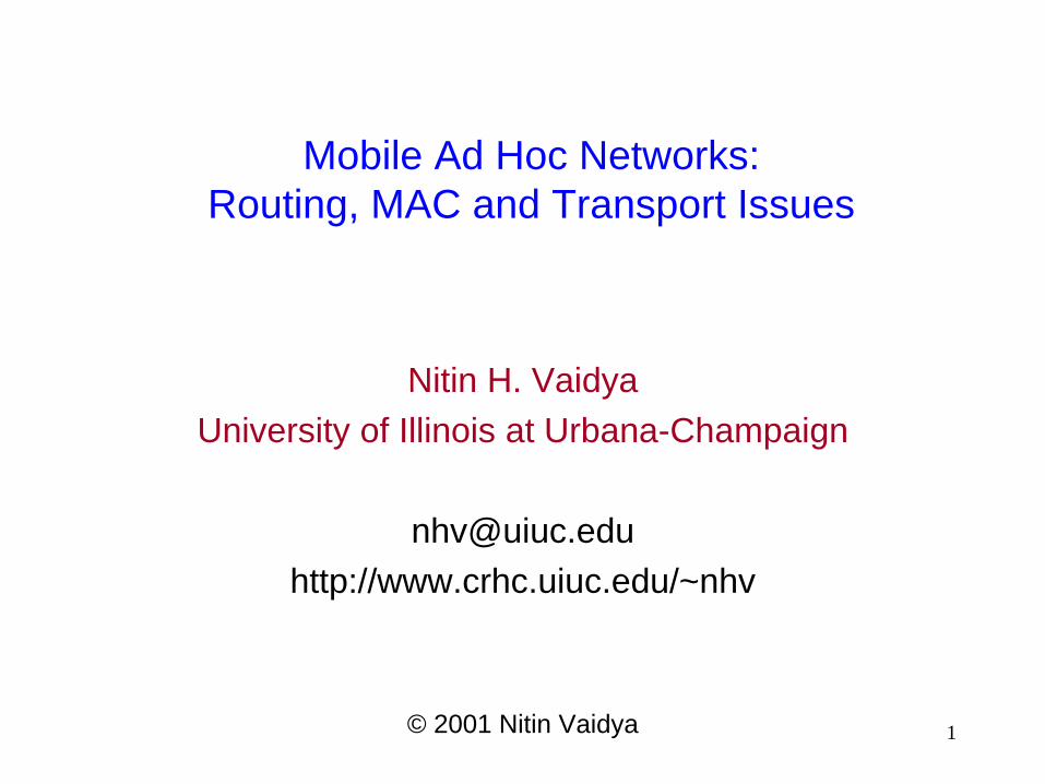
Mobile Ad Hoc Networks:
Routing, MAC and Transport Issues
Nitin H. Vaidya
University of Illinois at Urbana-Champaign
http://www.crhc.uiuc.edu/~nhv
© 2001 Nitin Vaidya
2
Notes
Names in brackets, as in [Xyz00], refer to a document in the list of references
The handout may not be as readable as the original slides, since the slides contain colored text and figures Note that different colors in the colored slides may look
identically black in the black-and-white handout

3
Tutorial Outline
Introduction
Unicast routing
Multicast routing
Geocast routing
Medium Access Control
Performance of UDP and TCP
Security Issues
Implementation Issues
Distributed Algorithms
Standards activities
Open problems

4
Statutory Warnings
Only most important features of various schemes are
typically discussed, i.e, features I consider as being
important
Others may disagree
Most schemes include many more details, and
optimizations
Not possible to cover all details in this tutorial
Be aware that some protocol specs have changed
several times
Jargon used to discuss a scheme may occasionally
differ from that used by the proposers
5
Coverage
Not intended to be exhaustive
Many interesting papers not covered in the tutorial
due to lack of time
No judgement on those papers is implied
6
Mobile Ad Hoc Networks (MANET)
Introduction and Generalities

7
Mobile Ad Hoc Networks
Formed by wireless hosts which may be mobile
Without (necessarily) using a pre-existing
infrastructure
Routes between nodes may potentially contain
multiple hops
8
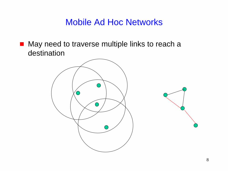
Mobile Ad Hoc Networks
May need to traverse multiple links to reach a
destination

9
Mobile Ad Hoc Networks (MANET)
Mobility causes route changes
10
Why Ad Hoc Networks ?
Ease of deployment
Speed of deployment
Decreased dependence on infrastructure
11
Many Applications
Personal area networking
cell phone, laptop, ear phone, wrist watch
Military environments
soldiers, tanks, planes
Civilian environments
taxi cab network
meeting rooms
sports stadiums
boats, small aircraft
Emergency operations
search-and-rescue
policing and fire fighting

12
Many Variations
Fully Symmetric Environment
all nodes have identical capabilities and responsibilities
Asymmetric Capabilities
transmission ranges and radios may differ
battery life at different nodes may differ
processing capacity may be different at different nodes
speed of movement
Asymmetric Responsibilities
only some nodes may route packets
some nodes may act as leaders of nearby nodes (e.g.,
cluster head)
13
Many Variations
Traffic characteristics may differ in different ad hoc
networks
bit rate
timeliness constraints
reliability requirements
unicast / multicast / geocast
host-based addressing / content-based addressing /
capability-based addressing
May co-exist (and co-operate) with an infrastructure-
based network

14
Many Variations
Mobility patterns may be different
people sitting at an airport lounge
New York taxi cabs
kids playing
military movements
personal area network
Mobility characteristics
speed
predictability
• direction of movement
• pattern of movement
uniformity (or lack thereof) of mobility characteristics among
different nodes

15
Challenges
Limited wireless transmission range
Broadcast nature of the wireless medium
Hidden terminal problem (see next slide)
Packet losses due to transmission errors
Mobility-induced route changes
Mobility-induced packet losses
Battery constraints
Potentially frequent network partitions
Ease of snooping on wireless transmissions (security
hazard)

16
Hidden Terminal Problem
B C A
Nodes A and C cannot hear each other
Transmissions by nodes A and C can collide at node B
Nodes A and C are hidden from each other
17
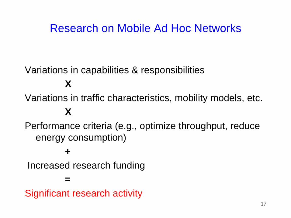
Research on Mobile Ad Hoc Networks
Variations in capabilities & responsibilities
X
Variations in traffic characteristics, mobility models, etc.
X
Performance criteria (e.g., optimize throughput, reduce
energy consumption)
+
Increased research funding
=
Significant research activity
18
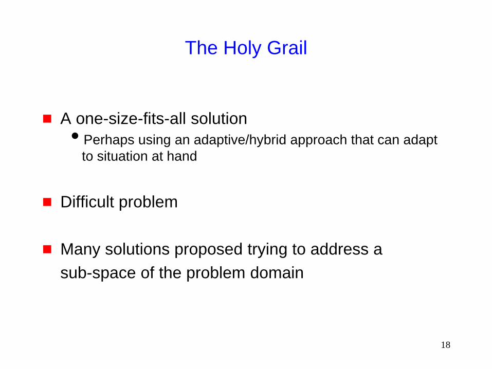
The Holy Grail
A one-size-fits-all solution
Perhaps using an adaptive/hybrid approach that can adapt
to situation at hand
Difficult problem
Many solutions proposed trying to address a
sub-space of the problem domain
19
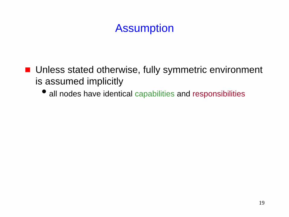
Assumption
Unless stated otherwise, fully symmetric environment
is assumed implicitly
all nodes have identical capabilities and responsibilities
20
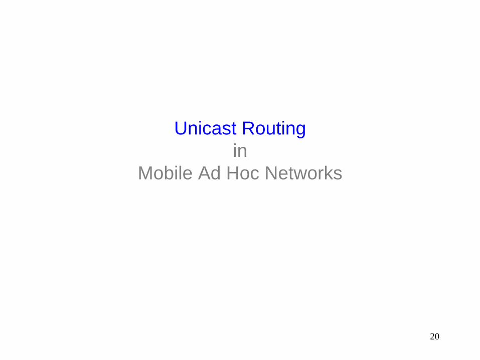
Unicast Routing
in
Mobile Ad Hoc Networks

21
Why is Routing in MANET different ?
Host mobility
link failure/repair due to mobility may have different
characteristics than those due to other causes
Rate of link failure/repair may be high when nodes
move fast
New performance criteria may be used
route stability despite mobility
energy consumption
22
Unicast Routing Protocols
Many protocols have been proposed
Some have been invented specifically for MANET
Others are adapted from previously proposed
protocols for wired networks
No single protocol works well in all environments
some attempts made to develop adaptive protocols
23
Routing Protocols
Proactive protocols
Determine routes independent of traffic pattern
Traditional link-state and distance-vector routing protocols
are proactive
Reactive protocols
Maintain routes only if needed
Hybrid protocols
24
Trade-Off
Latency of route discovery
Proactive protocols may have lower latency since routes are
maintained at all times
Reactive protocols may have higher latency because a route
from X to Y will be found only when X attempts to send to Y
Overhead of route discovery/maintenance
Reactive protocols may have lower overhead since routes
are determined only if needed
Proactive protocols can (but not necessarily) result in higher
overhead due to continuous route updating
Which approach achieves a better trade-off depends
on the traffic and mobility patterns

25
Overview of Unicast Routing Protocols

26
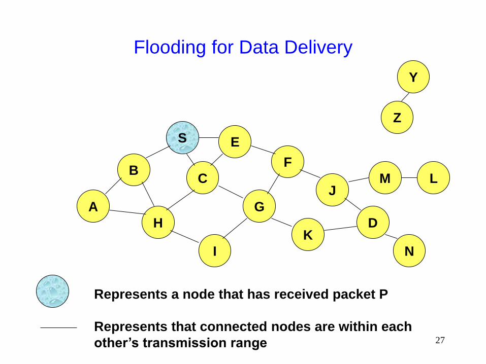
Flooding for Data Delivery
Sender S broadcasts data packet P to all its
neighbors
Each node receiving P forwards P to its neighbors
Sequence numbers used to avoid the possibility of
forwarding the same packet more than once
Packet P reaches destination D provided that D is
reachable from sender S
Node D does not forward the packet
27
Flooding for Data Delivery
B
A
S E
F
H
J
D
C
G
I
K
Represents that connected nodes are within each
other’s transmission range
Z
Y
Represents a node that has received packet P
M
N
L

28
Flooding for Data Delivery
B
A
S E
F
H
J
D
C
G
I
K
Represents transmission of packet P
Represents a node that receives packet P for
the first time
Z
Y Broadcast transmission
M
N
L

29
Flooding for Data Delivery
B
A
S E
F
H
J
D
C
G
I
K
• Node H receives packet P from two neighbors:
potential for collision
Z
Y
M
N
L

30
Flooding for Data Delivery
B
A
S E
F
H
J
D
C
G
I
K
• Node C receives packet P from G and H, but does not forward
it again, because node C has already forwarded packet P once
Z
Y
M
N
L
31
Flooding for Data Delivery
B
A
S E
F
H
J
D
C
G
I
K
Z
Y
M
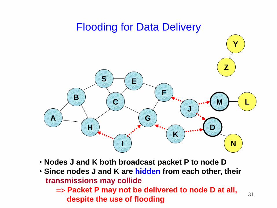
• Nodes J and K both broadcast packet P to node D
• Since nodes J and K are hidden from each other, their
transmissions may collide
=> Packet P may not be delivered to node D at all,
despite the use of flooding
N
L
32
Flooding for Data Delivery
B
A
S E
F
H
J
D
C
G
I
K
Z
Y
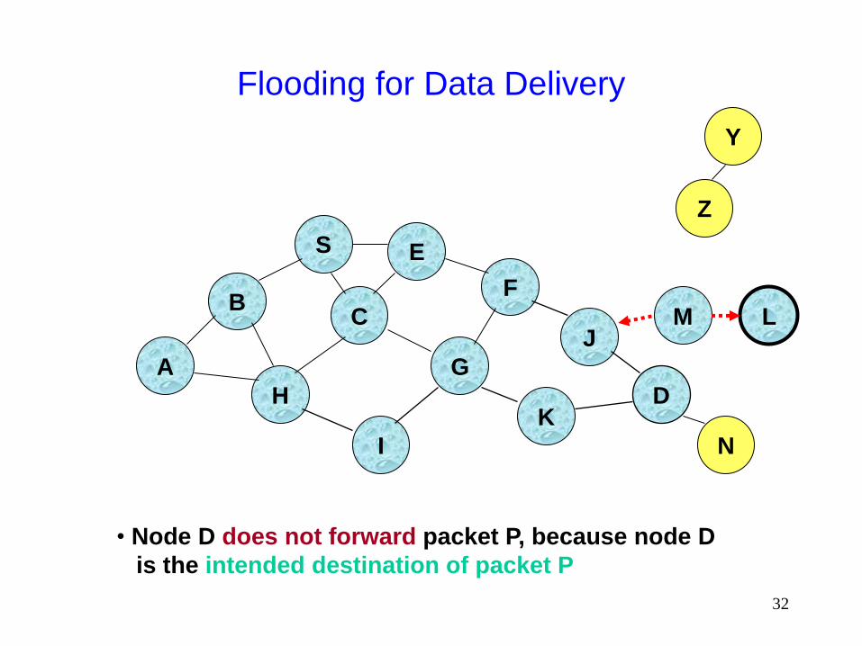
• Node D does not forward packet P, because node D
is the intended destination of packet P
M
N
L
33
Flooding for Data Delivery
B
A
S E
F
H
J
D
C
G
I
K
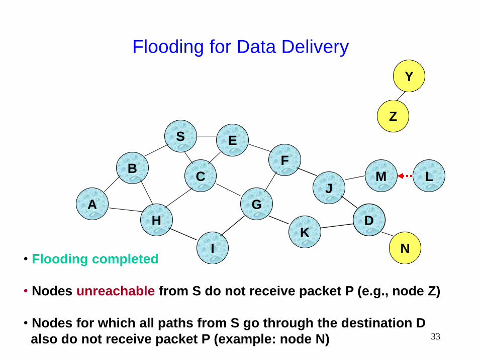
• Flooding completed
• Nodes unreachable from S do not receive packet P (e.g., node Z)
• Nodes for which all paths from S go through the destination D
also do not receive packet P (example: node N)
Z
Y
M
N
L

34
Flooding for Data Delivery
B
A
S E
F
H
J
D
C
G
I
K
• Flooding may deliver packets to too many nodes
(in the worst case, all nodes reachable from sender
may receive the packet)
Z
Y
M
N
L

35
Flooding for Data Delivery: Advantages
Simplicity
May be more efficient than other protocols when rate
of information transmission is low enough that the
overhead of explicit route discovery/maintenance
incurred by other protocols is relatively higher
this scenario may occur, for instance, when nodes transmit
small data packets relatively infrequently, and many topology
changes occur between consecutive packet transmissions
Potentially higher reliability of data delivery
Because packets may be delivered to the destination on
multiple paths

36
Flooding for Data Delivery: Disadvantages
Potentially, very high overhead
Data packets may be delivered to too many nodes who do
not need to receive them
Potentially lower reliability of data delivery
Flooding uses broadcasting -- hard to implement reliable
broadcast delivery without significantly increasing overhead
– Broadcasting in IEEE 802.11 MAC is unreliable
In our example, nodes J and K may transmit to node D
simultaneously, resulting in loss of the packet
– in this case, destination would not receive the packet at all

37
Flooding of Control Packets
Many protocols perform (potentially limited) flooding
of control packets, instead of data packets
The control packets are used to discover routes
Discovered routes are subsequently used to send
data packet(s)
Overhead of control packet flooding is amortized over
data packets transmitted between consecutive
control packet floods
38
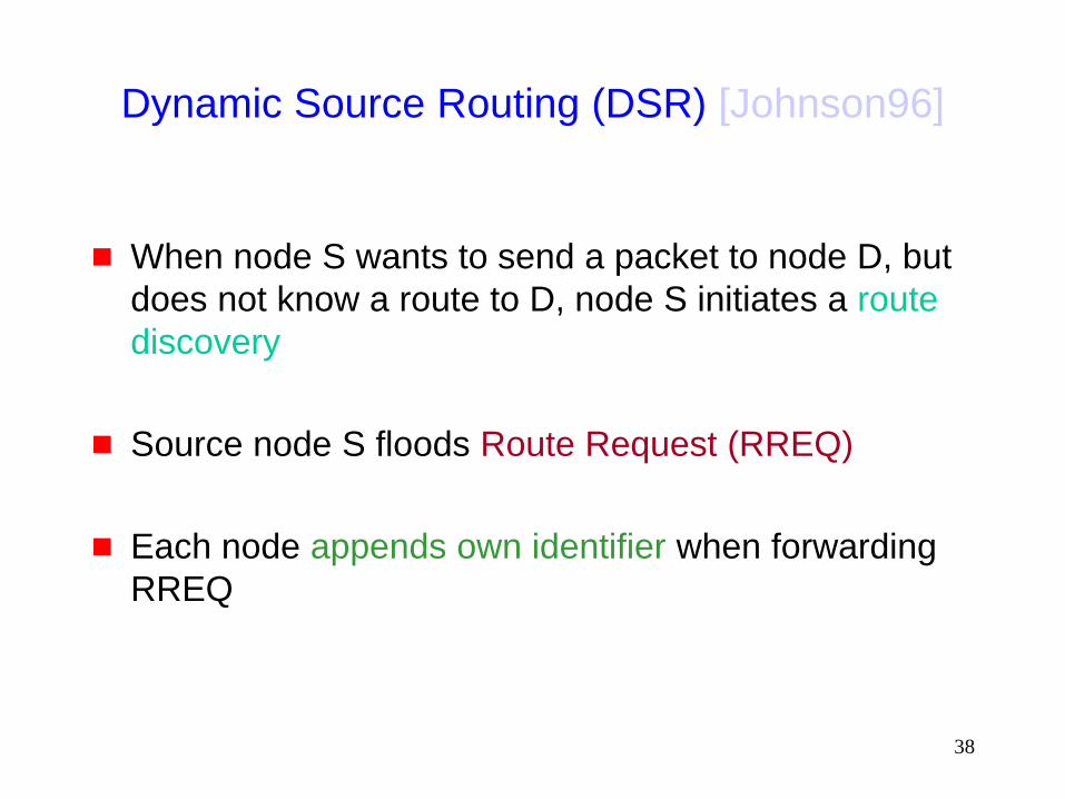
Dynamic Source Routing (DSR) [Johnson96]
When node S wants to send a packet to node D, but
does not know a route to D, node S initiates a route
discovery
Source node S floods Route Request (RREQ)
Each node appends own identifier when forwarding
RREQ

39
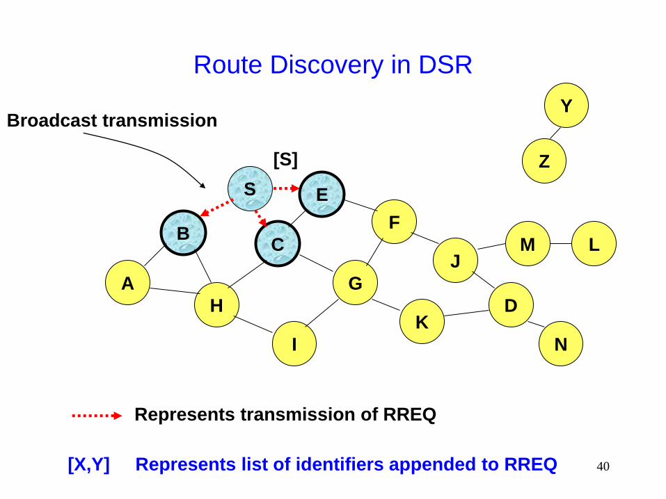
Route Discovery in DSR
B
A
S E
F
H
J
D
C
G
I
K
Z
Y
Represents a node that has received RREQ for D from S
M
N
L
40
Route Discovery in DSR
B
A
S E
F
H
J
D
C
G
I
K
Represents transmission of RREQ
Z
Y Broadcast transmission
M
N
L
[S]
[X,Y] Represents list of identifiers appended to RREQ
41
Route Discovery in DSR
B
A
S E
F
H
J
D
C
G
I
K
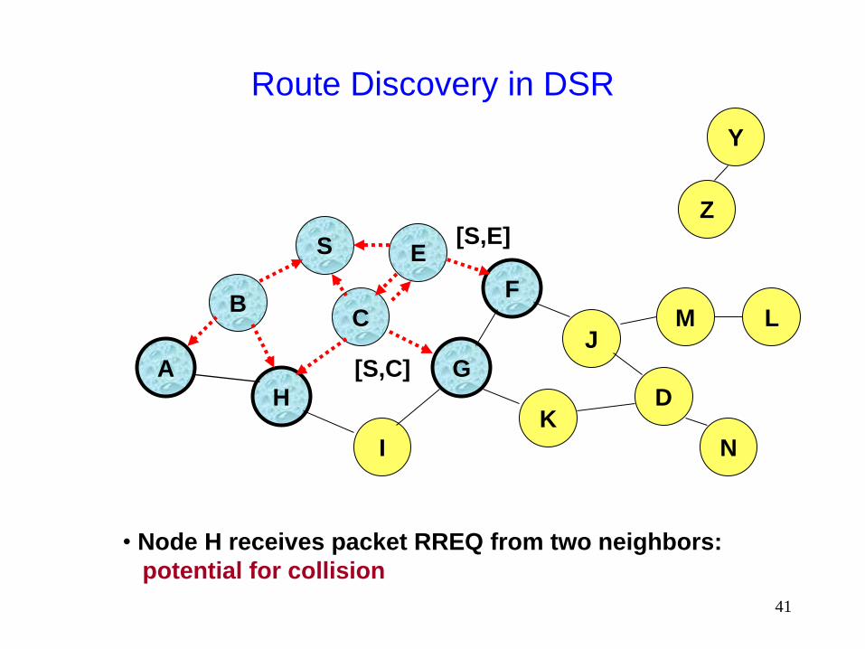
• Node H receives packet RREQ from two neighbors:
potential for collision
Z
Y
M
N
L
[S,E]
[S,C]
42
Route Discovery in DSR
B
A
S E
F
H
J
D
C
G
I
K
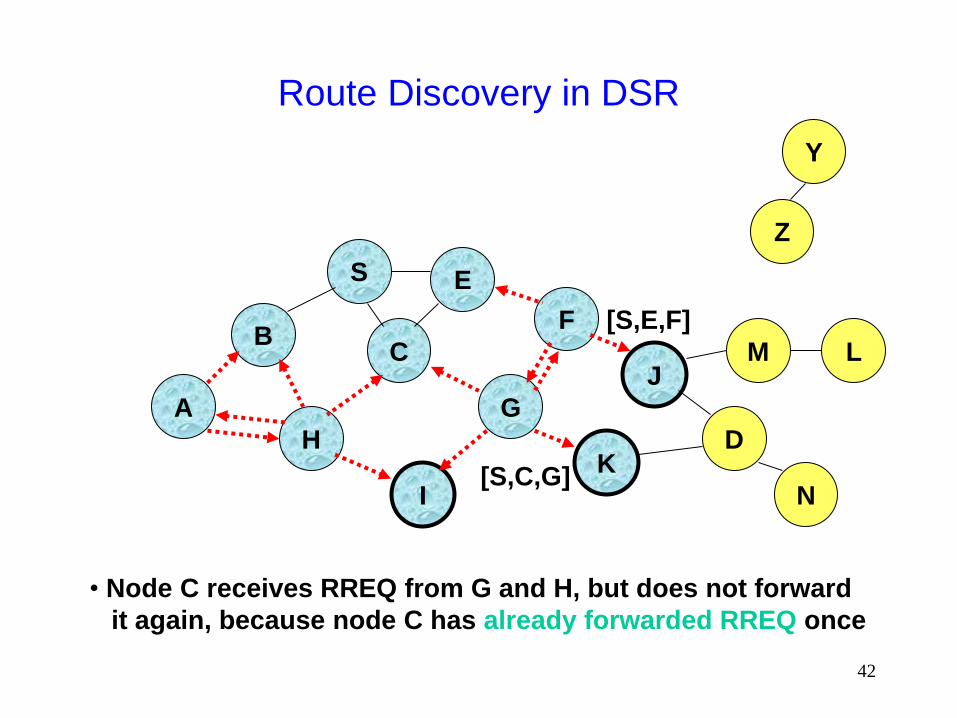
• Node C receives RREQ from G and H, but does not forward
it again, because node C has already forwarded RREQ once
Z
Y
M
N
L
[S,C,G]
[S,E,F]
43
Route Discovery in DSR
B
A
S E
F
H
J
D
C
G
I
K
Z
Y
M
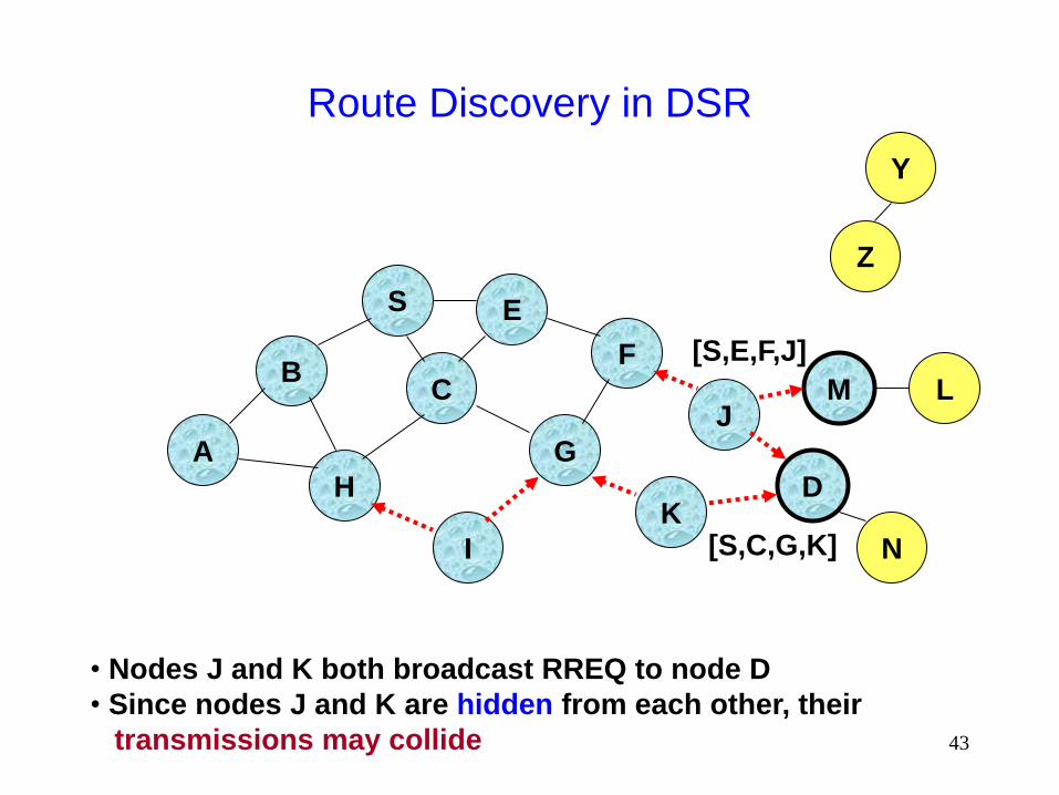
• Nodes J and K both broadcast RREQ to node D
• Since nodes J and K are hidden from each other, their
transmissions may collide
N
L
[S,C,G,K]
[S,E,F,J]
44
Route Discovery in DSR
B
A
S E
F
H
J
D
C
G
I
K
Z
Y
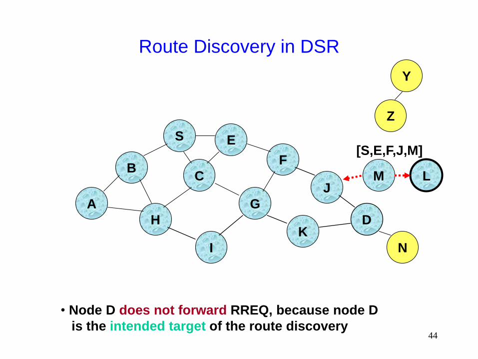
• Node D does not forward RREQ, because node D
is the intended target of the route discovery
M
N
L
[S,E,F,J,M]

45
Route Discovery in DSR
Destination D on receiving the first RREQ, sends a
Route Reply (RREP)
RREP is sent on a route obtained by reversing the
route appended to received RREQ
RREP includes the route from S to D on which RREQ
was received by node D

46
Route Reply in DSR
B
A
S E
F
H
J
D
C
G
I
K
Z
Y
M
N
L
RREP [S,E,F,J,D]
Represents RREP control message

47
Route Reply in DSR
Route Reply can be sent by reversing the route in
Route Request (RREQ) only if links are guaranteed
to be bi-directional
To ensure this, RREQ should be forwarded only if it received
on a link that is known to be bi-directional
If unidirectional (asymmetric) links are allowed, then
RREP may need a route discovery for S from node D
Unless node D already knows a route to node S
If a route discovery is initiated by D for a route to S, then the
Route Reply is piggybacked on the Route Request from D.
If IEEE 802.11 MAC is used to send data, then links
have to be bi-directional (since Ack is used)
48
Dynamic Source Routing (DSR)
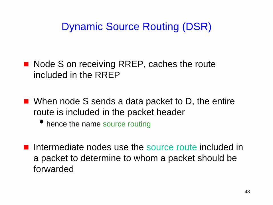
Node S on receiving RREP, caches the route
included in the RREP
When node S sends a data packet to D, the entire
route is included in the packet header
hence the name source routing
Intermediate nodes use the source route included in
a packet to determine to whom a packet should be
forwarded

49
Data Delivery in DSR
B
A
S E
F
H
J
D
C
G
I
K
Z
Y
M
N
L
DATA [S,E,F,J,D]
Packet header size grows with route length
50
When to Perform a Route Discovery
When node S wants to send data to node D, but does
not know a valid route node D
51
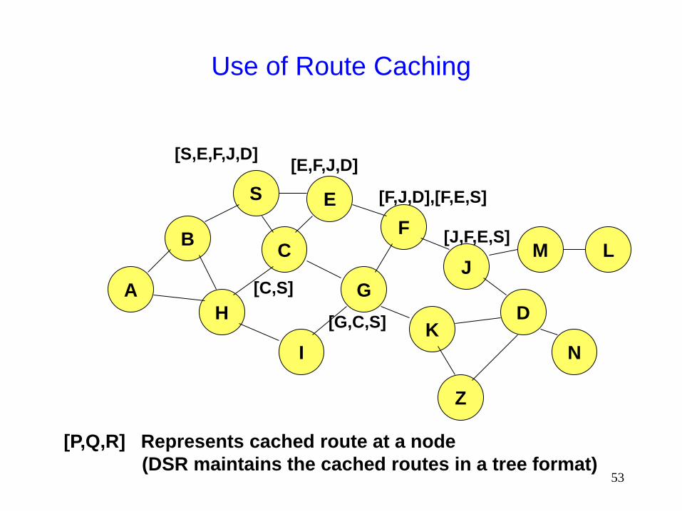
DSR Optimization: Route Caching
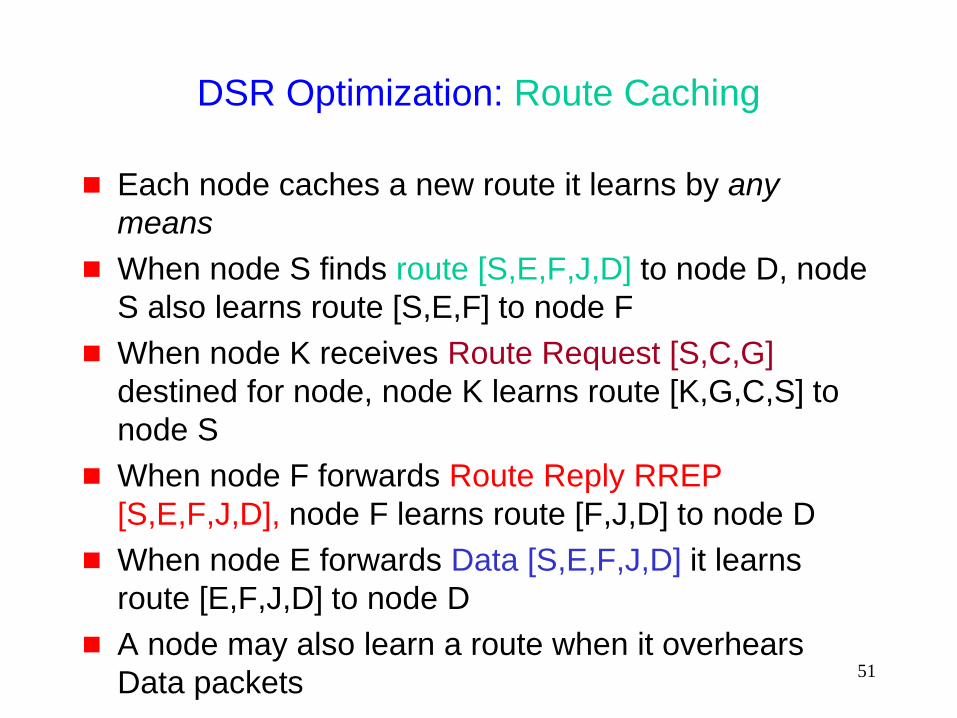
Each node caches a new route it learns by any
means
When node S finds route [S,E,F,J,D] to node D, node
S also learns route [S,E,F] to node F
When node K receives Route Request [S,C,G]
destined for node, node K learns route [K,G,C,S] to
node S
When node F forwards Route Reply RREP
[S,E,F,J,D], node F learns route [F,J,D] to node D
When node E forwards Data [S,E,F,J,D] it learns
route [E,F,J,D] to node D
A node may also learn a route when it overhears
Data packets
52
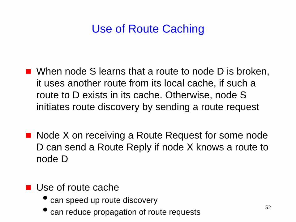
Use of Route Caching
When node S learns that a route to node D is broken,
it uses another route from its local cache, if such a
route to D exists in its cache. Otherwise, node S
initiates route discovery by sending a route request
Node X on receiving a Route Request for some node
D can send a Route Reply if node X knows a route to
node D
Use of route cache
can speed up route discovery
can reduce propagation of route requests
53
Use of Route Caching
B
A
S E
F
H
J
D
C
G
I
K
[P,Q,R] Represents cached route at a node
(DSR maintains the cached routes in a tree format)
M
N
L
[S,E,F,J,D] [E,F,J,D]
[C,S]
[G,C,S]
[F,J,D],[F,E,S]
[J,F,E,S]
Z
54
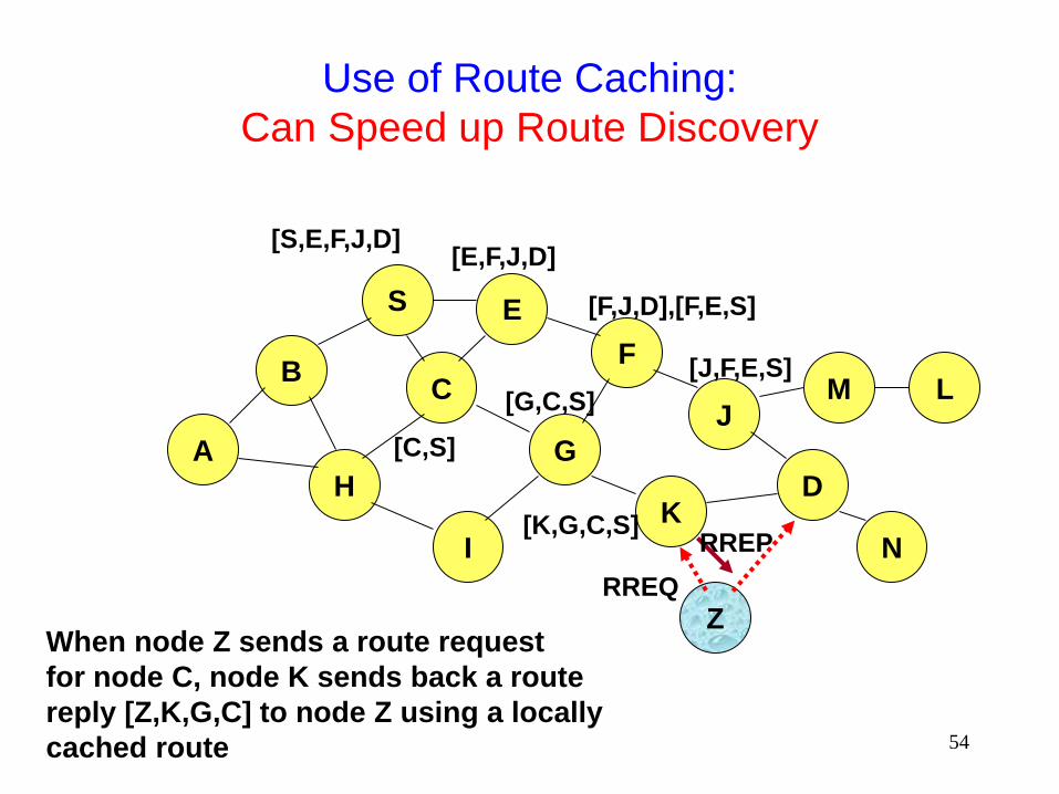
Use of Route Caching:
Can Speed up Route Discovery
B
A
S E
F
H
J
D
C
G
I
K
Z
M
N
L
[S,E,F,J,D] [E,F,J,D]
[C,S]
[G,C,S]
[F,J,D],[F,E,S]
[J,F,E,S]
RREQ
When node Z sends a route request
for node C, node K sends back a route
reply [Z,K,G,C] to node Z using a locally
cached route
[K,G,C,S] RREP

55
Use of Route Caching:
Can Reduce Propagation of Route Requests
B
A
S E
F
H
J
D
C
G
I
K
Z
Y
M
N
L
[S,E,F,J,D] [E,F,J,D]
[C,S]
[G,C,S]
[F,J,D],[F,E,S]
[J,F,E,S]
RREQ
Assume that there is no link between D and Z.
Route Reply (RREP) from node K limits flooding of RREQ.
In general, the reduction may be less dramatic.
[K,G,C,S]
RREP

56
Route Error (RERR)
B
A
S E
F
H
J
D
C
G
I
K
Z
Y
M
N
L
RERR [J-D]
J sends a route error to S along route J-F-E-S when its attempt to
forward the data packet S (with route SEFJD) on J-D fails
Nodes hearing RERR update their route cache to remove link J-D
57
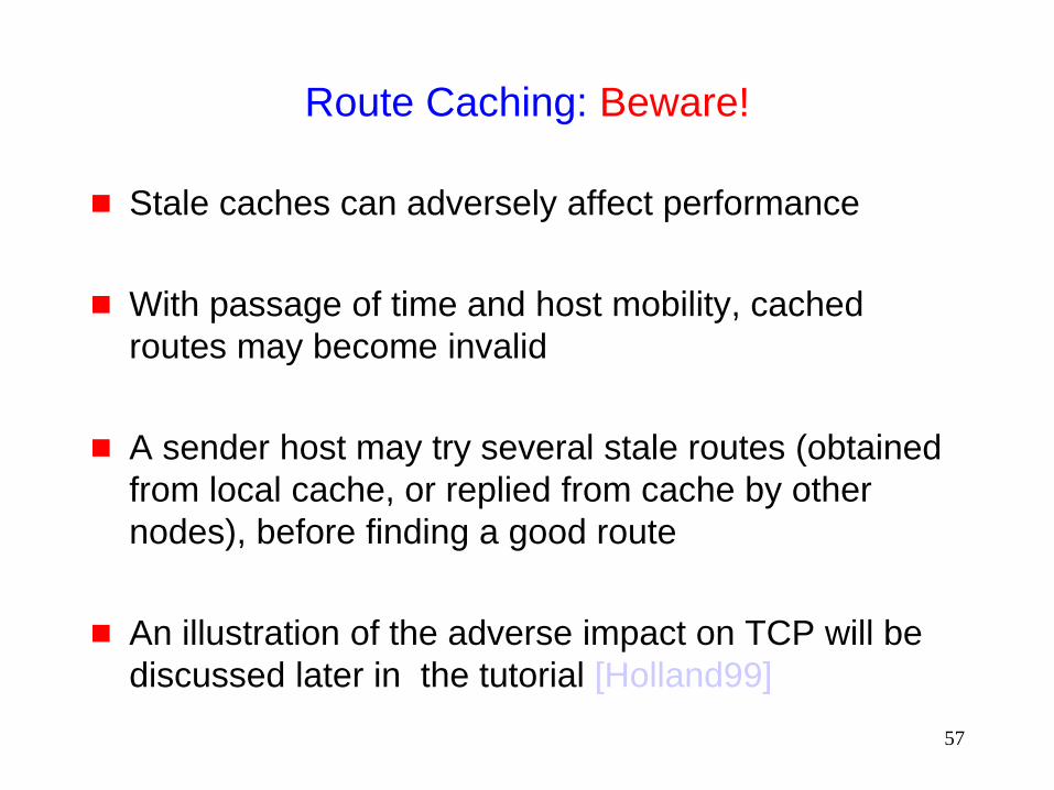
Route Caching: Beware!
Stale caches can adversely affect performance
With passage of time and host mobility, cached
routes may become invalid
A sender host may try several stale routes (obtained
from local cache, or replied from cache by other
nodes), before finding a good route
An illustration of the adverse impact on TCP will be
discussed later in the tutorial [Holland99]

58
Dynamic Source Routing: Advantages
Routes maintained only between nodes who need to
communicate
reduces overhead of route maintenance
Route caching can further reduce route discovery
overhead
A single route discovery may yield many routes to the
destination, due to intermediate nodes replying from
local caches
59
Dynamic Source Routing: Disadvantages
Packet header size grows with route length due to
source routing
Flood of route requests may potentially reach all
nodes in the network
Care must be taken to avoid collisions between route
requests propagated by neighboring nodes
insertion of random delays before forwarding RREQ
Increased contention if too many route replies come
back due to nodes replying using their local cache
Route Reply Storm problem
Reply storm may be eased by preventing a node from
sending RREP if it hears another RREP with a shorter route
60
Dynamic Source Routing: Disadvantages
An intermediate node may send Route Reply using a stale cached route, thus polluting other caches
This problem can be eased if some mechanism to purge (potentially) invalid cached routes is incorporated.
For some proposals for cache invalidation, see [Hu00Mobicom] Static timeouts
Adaptive timeouts based on link stability

61
Flooding of Control Packets
How to reduce the scope of the route request flood ?
LAR [Ko98Mobicom]
Query localization [Castaneda99Mobicom]
How to reduce redundant broadcasts ?
The Broadcast Storm Problem [Ni99Mobicom]

62
Location-Aided Routing (LAR) [Ko98Mobicom]
Exploits location information to limit scope of route
request flood
Location information may be obtained using GPS
Expected Zone is determined as a region that is
expected to hold the current location of the
destination
Expected region determined based on potentially old
location information, and knowledge of the destination’s
speed
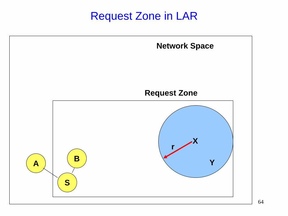
Route requests limited to a Request Zone that
contains the Expected Zone and location of the
sender node
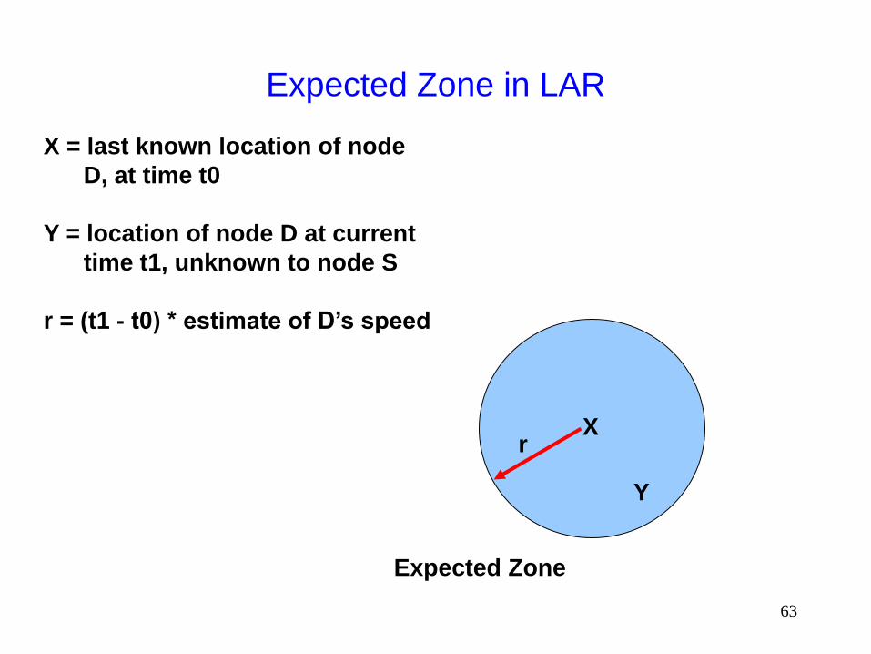
63
Expected Zone in LAR
X
Y
r
X = last known location of node
D, at time t0
Y = location of node D at current
time t1, unknown to node S
r = (t1 - t0) * estimate of D’s speed
Expected Zone
64
Request Zone in LAR
X
Y
r
S
Request Zone
Network Space
B A

65
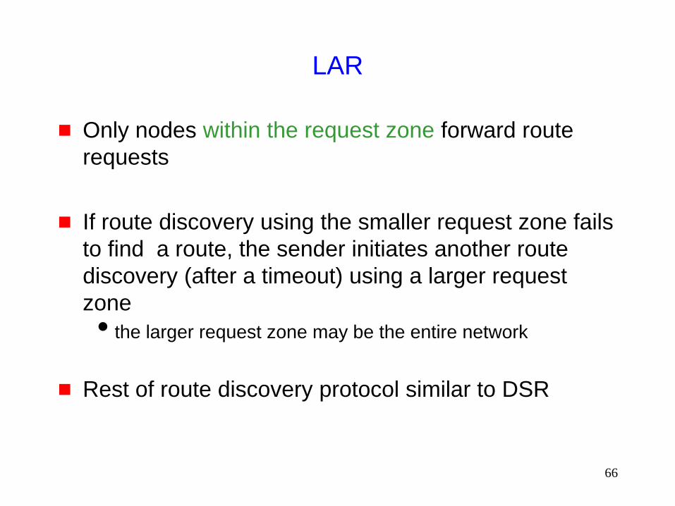
LAR
Only nodes within the request zone forward route
requests
Node A does not forward RREQ, but node B does (see
previous slide)
Request zone explicitly specified in the route request
Each node must know its physical location to
determine whether it is within the request zone
66
LAR
Only nodes within the request zone forward route
requests
If route discovery using the smaller request zone fails
to find a route, the sender initiates another route
discovery (after a timeout) using a larger request
zone
the larger request zone may be the entire network
Rest of route discovery protocol similar to DSR

67
LAR Variations: Adaptive Request Zone
Each node may modify the request zone included in
the forwarded request
Modified request zone may be determined using
more recent/accurate information, and may be
smaller than the original request zone
S
B
Request zone adapted by B
Request zone defined by sender S
68
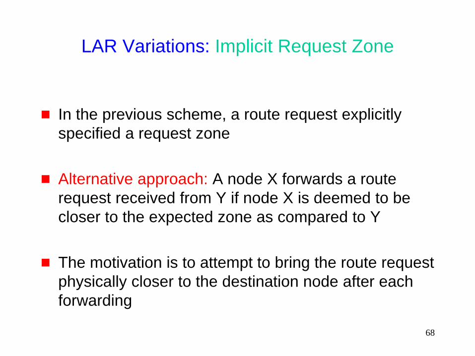
LAR Variations: Implicit Request Zone
In the previous scheme, a route request explicitly
specified a request zone
Alternative approach: A node X forwards a route
request received from Y if node X is deemed to be
closer to the expected zone as compared to Y
The motivation is to attempt to bring the route request
physically closer to the destination node after each
forwarding
69
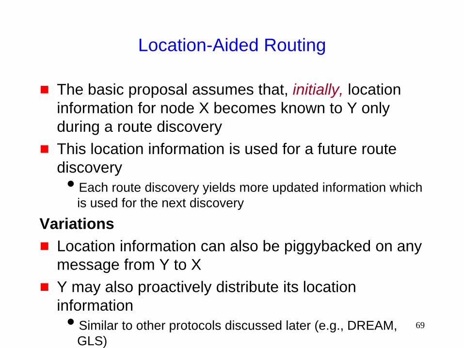
Location-Aided Routing
The basic proposal assumes that, initially, location
information for node X becomes known to Y only
during a route discovery
This location information is used for a future route
discovery
Each route discovery yields more updated information which
is used for the next discovery
Variations
Location information can also be piggybacked on any
message from Y to X
Y may also proactively distribute its location
information
Similar to other protocols discussed later (e.g., DREAM,
GLS)
70
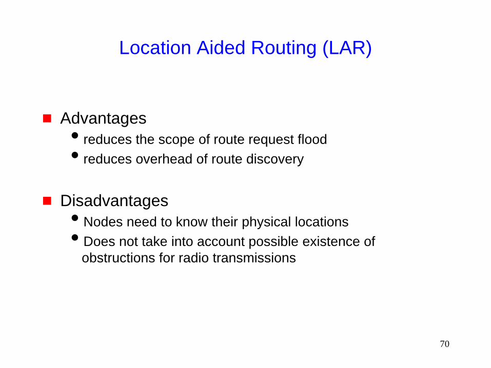
Location Aided Routing (LAR)
Advantages
reduces the scope of route request flood
reduces overhead of route discovery
Disadvantages
Nodes need to know their physical locations
Does not take into account possible existence of
obstructions for radio transmissions
71
Detour
Routing Using Location Information

72
Distance Routing Effect Algorithm for Mobility
(DREAM) [Basagni98Mobicom]
Uses location and speed information (like LAR)
DREAM uses flooding of data packets as the routing
mechanism (unlike LAR)
DREAM uses location information to limit the flood of data
packets to a small region

73
Distance Routing Effect Algorithm for Mobility
(DREAM)
S
D
Expected zone
(in the LAR jargon)
A
Node A, on receiving the
data packet, forwards it to
its neighbors within the
cone rooted at node A
S sends data packet to all
neighbors in the cone rooted
at node S

74
Distance Routing Effect Algorithm for Mobility
(DREAM)
Nodes periodically broadcast their physical location
Nearby nodes are updated more frequently, far away
nodes less frequently
Distance effect: Far away nodes seem to move at a
lower angular speed as compared to nearby nodes
Location update’s time-to-live field used to control
how far the information is propagated
75
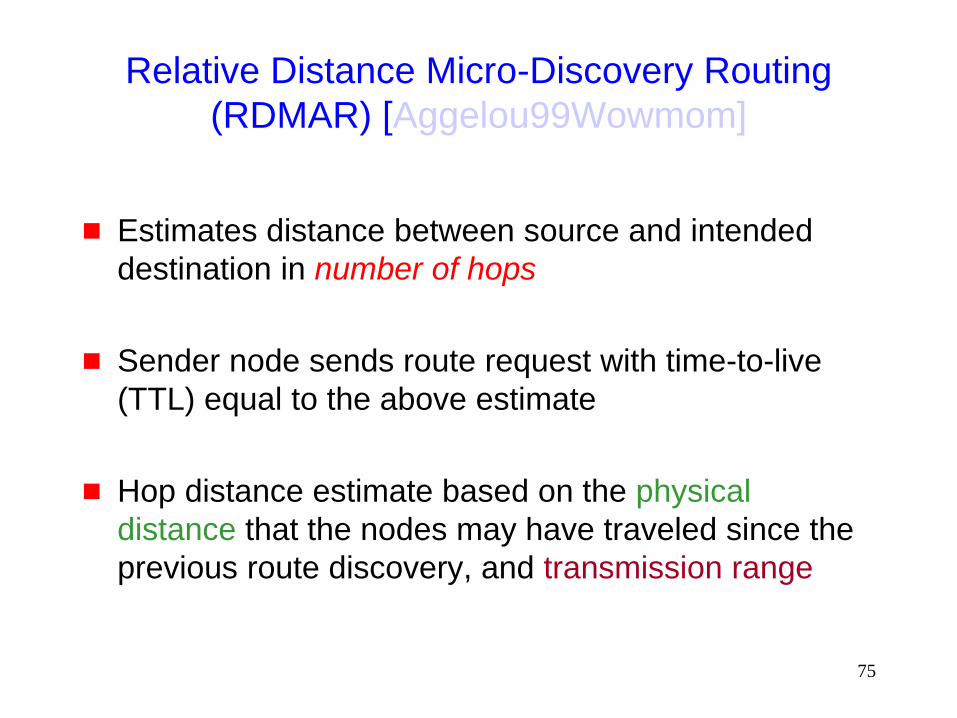
Relative Distance Micro-Discovery Routing
(RDMAR) [Aggelou99Wowmom]
Estimates distance between source and intended
destination in number of hops
Sender node sends route request with time-to-live
(TTL) equal to the above estimate
Hop distance estimate based on the physical
distance that the nodes may have traveled since the
previous route discovery, and transmission range
76
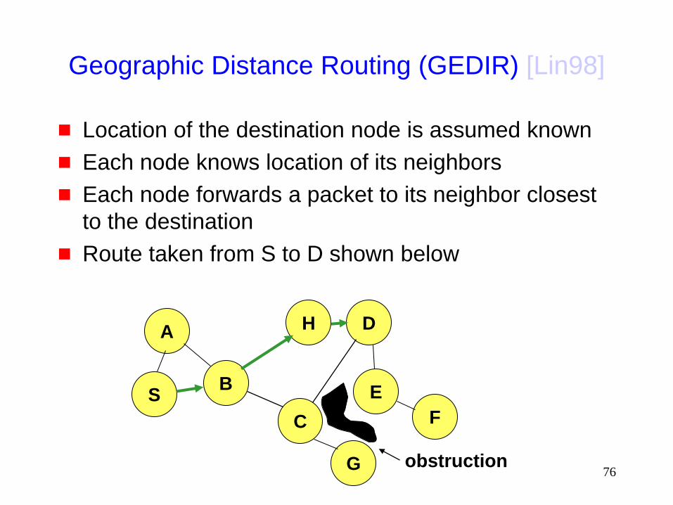
Geographic Distance Routing (GEDIR) [Lin98]
Location of the destination node is assumed known
Each node knows location of its neighbors
Each node forwards a packet to its neighbor closest
to the destination
Route taken from S to D shown below
S
A
B
D
C F
E
obstruction
H
G

77
Geographic Distance Routing (GEDIR)
[Stojmenovic99]
The algorithm terminates when same edge traversed
twice consecutively
Algorithm fails to route from S to E
Node G is the neighbor of C who is closest from destination
E, but C does not have a route to E
S
A
B
D
C F
E
obstruction
H
G
78
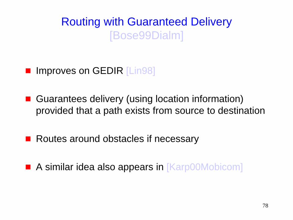
Routing with Guaranteed Delivery
[Bose99Dialm]
Improves on GEDIR [Lin98]
Guarantees delivery (using location information)
provided that a path exists from source to destination
Routes around obstacles if necessary
A similar idea also appears in [Karp00Mobicom]
79
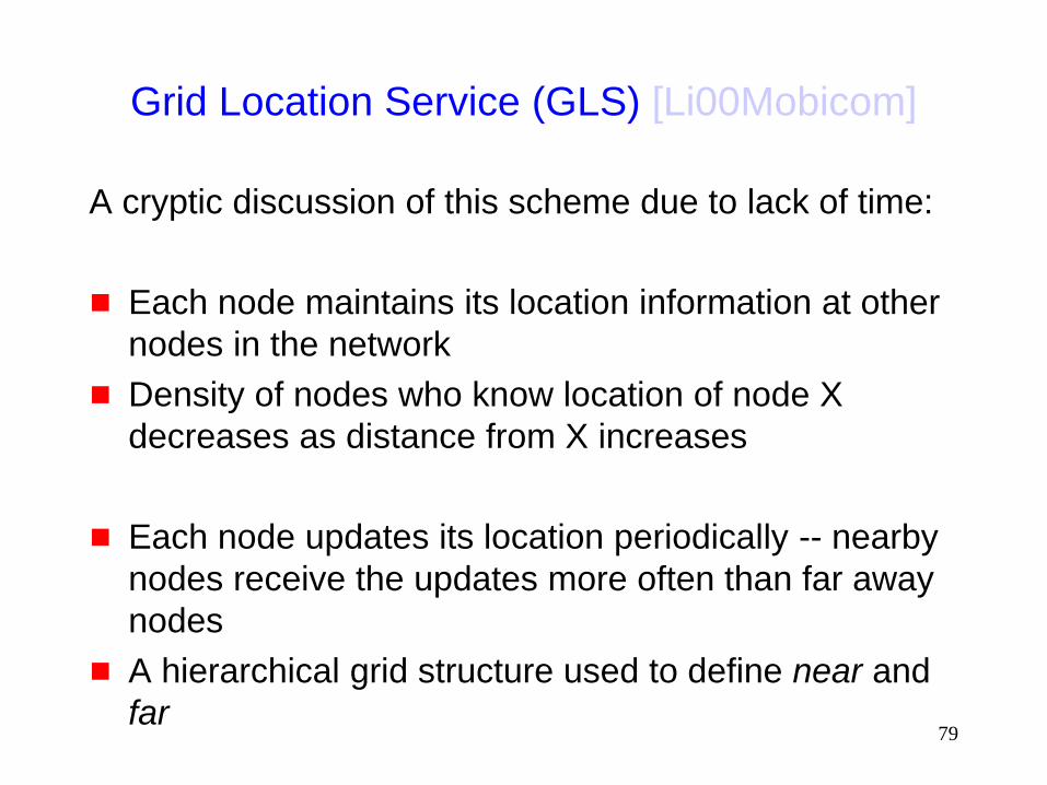
Grid Location Service (GLS) [Li00Mobicom]
A cryptic discussion of this scheme due to lack of time:
Each node maintains its location information at other
nodes in the network
Density of nodes who know location of node X
decreases as distance from X increases
Each node updates its location periodically -- nearby
nodes receive the updates more often than far away
nodes
A hierarchical grid structure used to define near and
far
80
Back to
Reducing Scope of
the Route Request Flood
End of
Detour
81
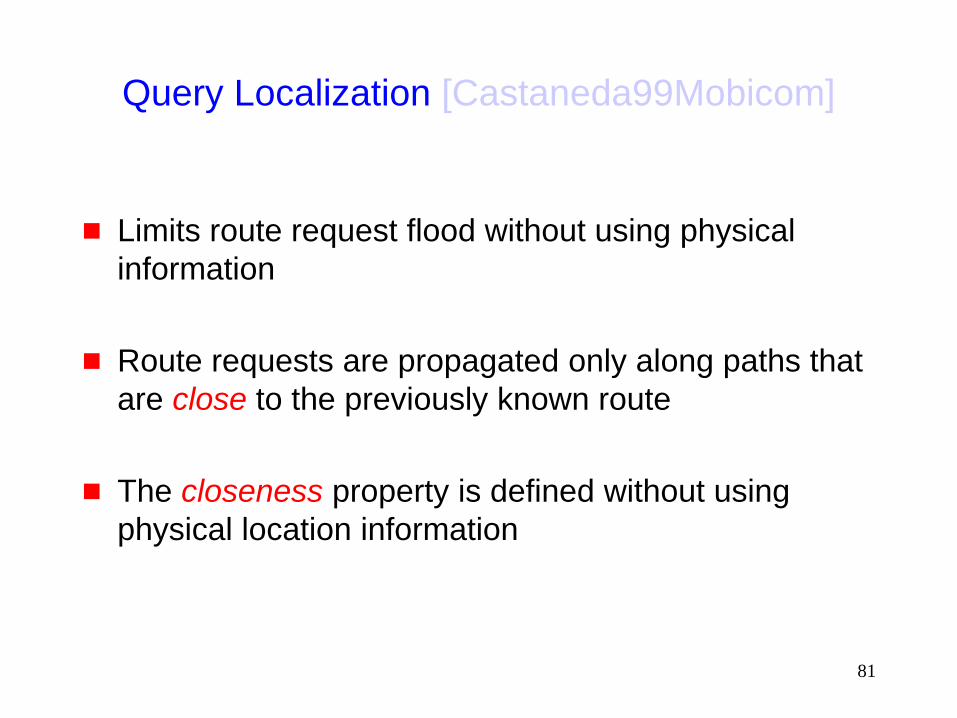
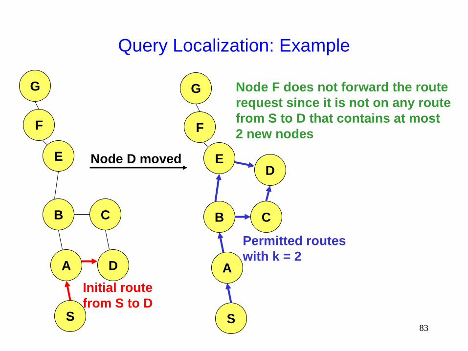
Query Localization [Castaneda99Mobicom]
Limits route request flood without using physical
information
Route requests are propagated only along paths that
are close to the previously known route
The closeness property is defined without using
physical location information
82
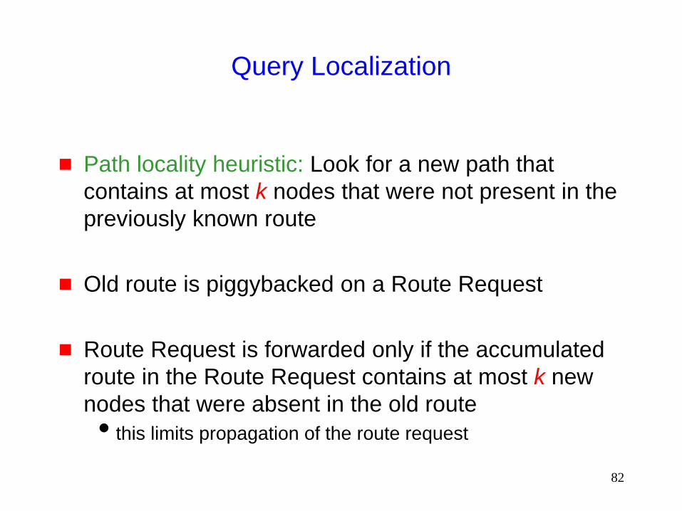
Query Localization
Path locality heuristic: Look for a new path that
contains at most k nodes that were not present in the
previously known route
Old route is piggybacked on a Route Request
Route Request is forwarded only if the accumulated
route in the Route Request contains at most k new
nodes that were absent in the old route
this limits propagation of the route request
83
Query Localization: Example
B
E
A
S
D
C
G
F
Initial route
from S to D
B
E
A
S
D
C
G
F
Permitted routes
with k = 2
Node F does not forward the route
request since it is not on any route
from S to D that contains at most
2 new nodes
Node D moved

84
Query Localization
Advantages:
Reduces overhead of route discovery without using physical
location information
Can perform better in presence of obstructions by searching
for new routes in the vicinity of old routes
Disadvantage:
May yield routes longer than LAR
(Shortest route may contain more than k new nodes)
85
B
D
C
A
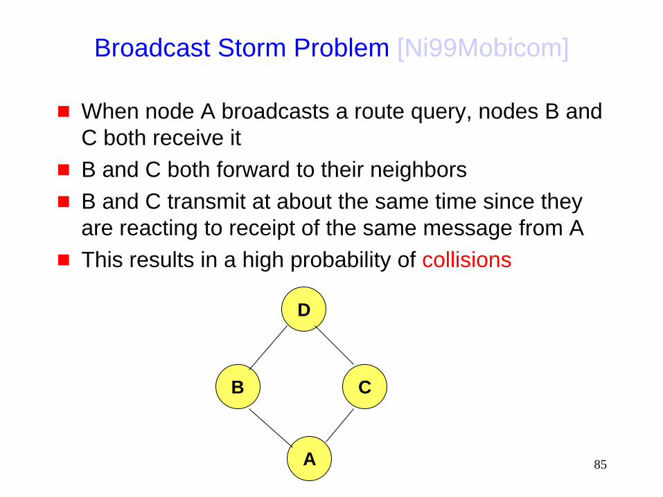
Broadcast Storm Problem [Ni99Mobicom]
When node A broadcasts a route query, nodes B and
C both receive it
B and C both forward to their neighbors
B and C transmit at about the same time since they
are reacting to receipt of the same message from A
This results in a high probability of collisions
86
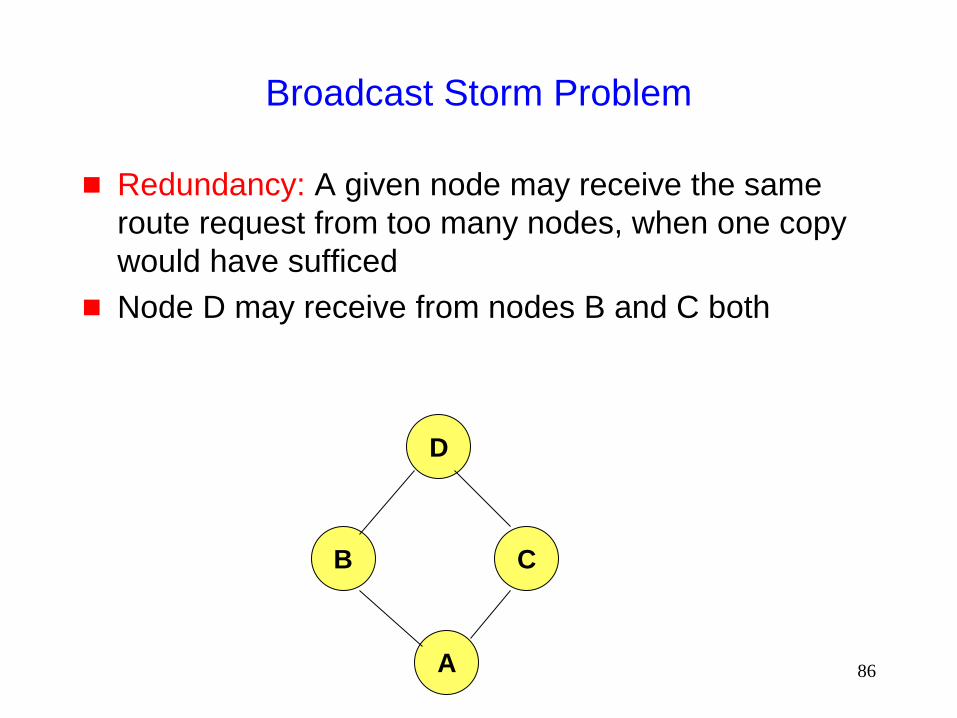
Broadcast Storm Problem
Redundancy: A given node may receive the same
route request from too many nodes, when one copy
would have sufficed
Node D may receive from nodes B and C both
B
D
C
A

87
Solutions for Broadcast Storm
Probabilistic scheme: On receiving a route request for
the first time, a node will re-broadcast (forward) the
request with probability p
Also, re-broadcasts by different nodes should be
staggered by using a collision avoidance technique (wait
a random delay when channel is idle)
this would reduce the probability that nodes B and C would
forward a packet simultaneously in the previous example

88
B
D
C
A
F
E
Solutions for Broadcast Storms
Counter-Based Scheme: If node E hears more than k
neighbors broadcasting a given route request, before
it can itself forward it, then node E will not forward the
request
Intuition: k neighbors together have probably already
forwarded the request to all of E’s neighbors

89
E
Z <d
Solutions for Broadcast Storms
Distance-Based Scheme: If node E hears RREQ
broadcasted by some node Z within physical distance
d, then E will not re-broadcast the request
Intuition: Z and E are too close, so transmission
areas covered by Z and E are not very different if E re-broadcasts the request, not many nodes who have not
already heard the request from Z will hear the request
90
Summary: Broadcast Storm Problem
Flooding is used in many protocols, such as Dynamic
Source Routing (DSR)
Problems associated with flooding
collisions
redundancy
Collisions may be reduced by “jittering” (waiting for a
random interval before propagating the flood)
Redundancy may be reduced by selectively re-
broadcasting packets from only a subset of the nodes
91
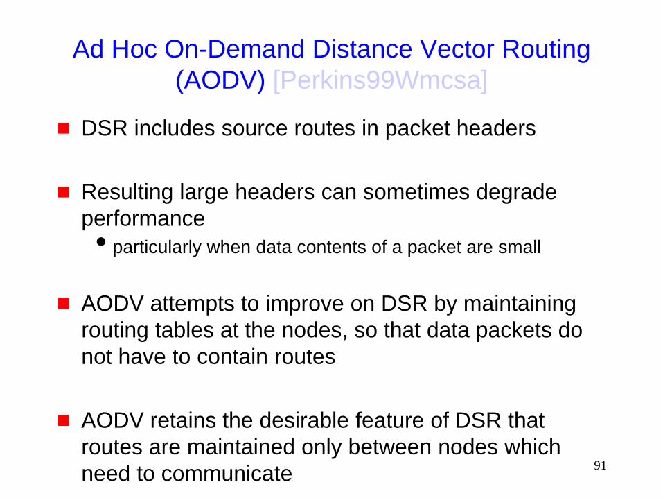
Ad Hoc On-Demand Distance Vector Routing
(AODV) [Perkins99Wmcsa]
DSR includes source routes in packet headers
Resulting large headers can sometimes degrade
performance
particularly when data contents of a packet are small
AODV attempts to improve on DSR by maintaining
routing tables at the nodes, so that data packets do
not have to contain routes
AODV retains the desirable feature of DSR that
routes are maintained only between nodes which
need to communicate

92
AODV
Route Requests (RREQ) are forwarded in a manner
similar to DSR
When a node re-broadcasts a Route Request, it sets
up a reverse path pointing towards the source
AODV assumes symmetric (bi-directional) links
When the intended destination receives a Route
Request, it replies by sending a Route Reply
Route Reply travels along the reverse path set-up
when Route Request is forwarded
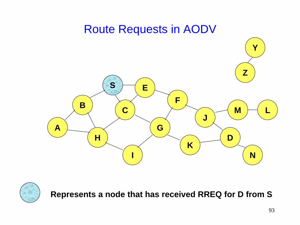
93
Route Requests in AODV
B
A
S E
F
H
J
D
C
G
I
K
Z
Y
Represents a node that has received RREQ for D from S
M
N
L

94
Route Requests in AODV
B
A
S E
F
H
J
D
C
G
I
K
Represents transmission of RREQ
Z
Y Broadcast transmission
M
N
L
95
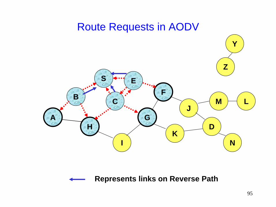
Route Requests in AODV
B
A
S E
F
H
J
D
C
G
I
K
Represents links on Reverse Path
Z
Y
M
N
L
96
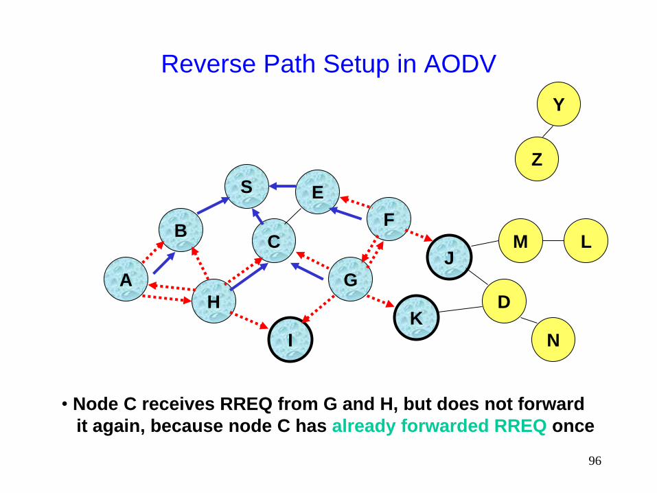
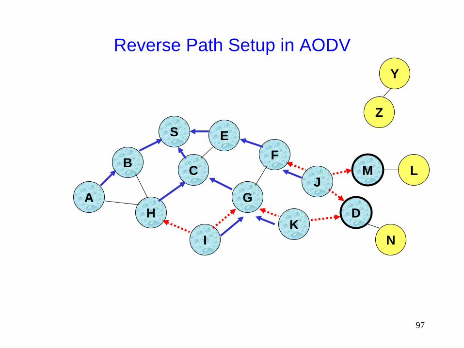
Reverse Path Setup in AODV
B
A
S E
F
H
J
D
C
G
I
K
• Node C receives RREQ from G and H, but does not forward
it again, because node C has already forwarded RREQ once
Z
Y
M
N
L
97
Reverse Path Setup in AODV
B
A
S E
F
H
J
D
C
G
I
K
Z
Y
M
N
L

98
Reverse Path Setup in AODV
B
A
S E
F
H
J
D
C
G
I
K
Z
Y
• Node D does not forward RREQ, because node D
is the intended target of the RREQ
M
N
L
99
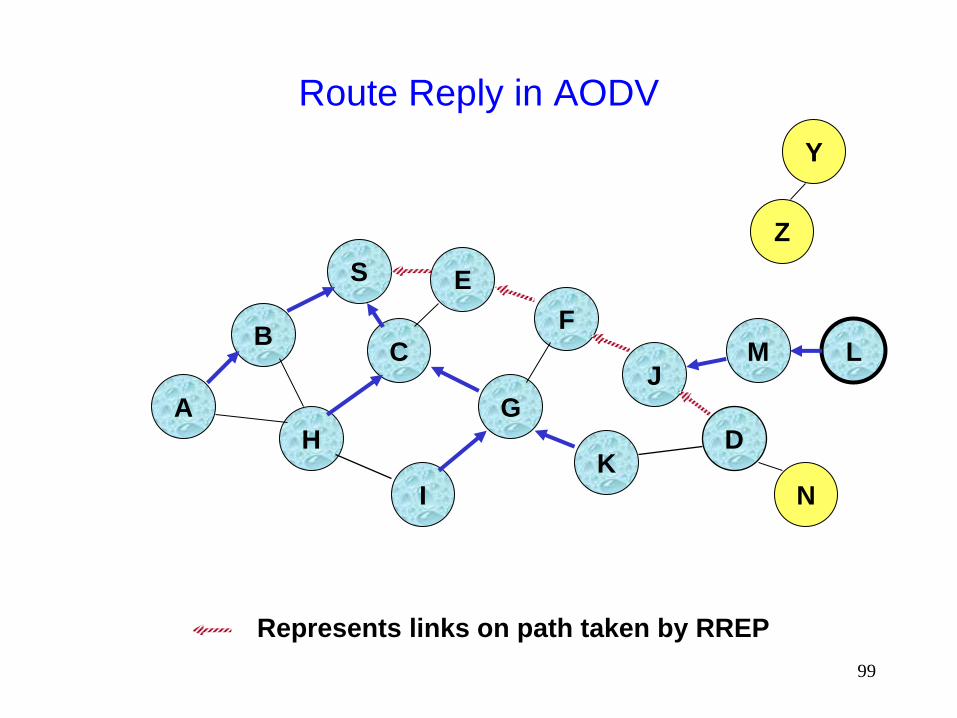
Route Reply in AODV
B
A
S E
F
H
J
D
C
G
I
K
Z
Y
Represents links on path taken by RREP
M
N
L
100
Route Reply in AODV
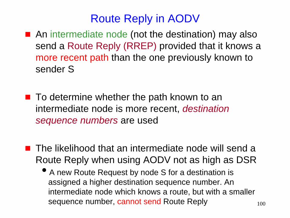
An intermediate node (not the destination) may also
send a Route Reply (RREP) provided that it knows a
more recent path than the one previously known to
sender S
To determine whether the path known to an
intermediate node is more recent, destination
sequence numbers are used
The likelihood that an intermediate node will send a
Route Reply when using AODV not as high as DSR
A new Route Request by node S for a destination is
assigned a higher destination sequence number. An
intermediate node which knows a route, but with a smaller
sequence number, cannot send Route Reply

101
Forward Path Setup in AODV
B
A
S E
F
H
J
D
C
G
I
K
Z
Y
M
N
L
Forward links are setup when RREP travels along
the reverse path
Represents a link on the forward path
102
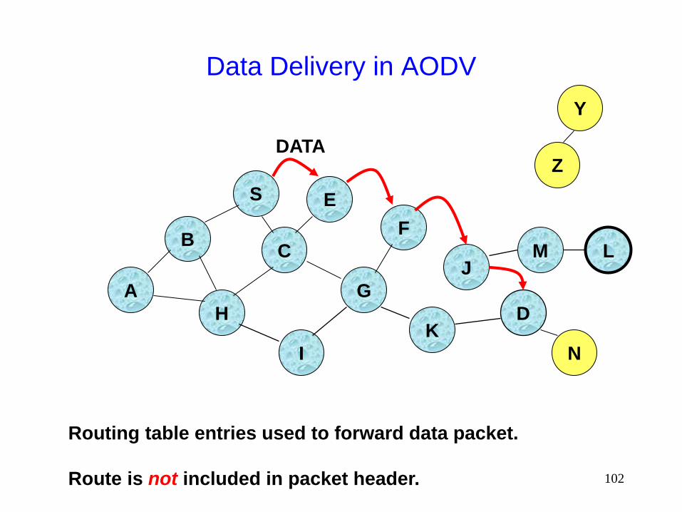
Data Delivery in AODV
B
A
S E
F
H
J
D
C
G
I
K
Z
Y
M
N
L
Routing table entries used to forward data packet.
Route is not included in packet header.
DATA

103
Timeouts
A routing table entry maintaining a reverse path is
purged after a timeout interval
timeout should be long enough to allow RREP to come back
A routing table entry maintaining a forward path is
purged if not used for a active_route_timeout interval
if no is data being sent using a particular routing table entry,
that entry will be deleted from the routing table (even if the
route may actually still be valid)
104
Link Failure Reporting
A neighbor of node X is considered active for a
routing table entry if the neighbor sent a packet within
active_route_timeout interval which was forwarded
using that entry
When the next hop link in a routing table entry
breaks, all active neighbors are informed
Link failures are propagated by means of Route Error
messages, which also update destination sequence
numbers
105
Route Error
When node X is unable to forward packet P (from
node S to node D) on link (X,Y), it generates a RERR
message
Node X increments the destination sequence number
for D cached at node X
The incremented sequence number N is included in
the RERR
When node S receives the RERR, it initiates a new
route discovery for D using destination sequence
number at least as large as N
106
Destination Sequence Number
Continuing from the previous slide …
When node D receives the route request with
destination sequence number N, node D will set its
sequence number to N, unless it is already larger
than N
107
Link Failure Detection
Hello messages: Neighboring nodes periodically
exchange hello message
Absence of hello message is used as an indication of
link failure
Alternatively, failure to receive several MAC-level
acknowledgement may be used as an indication of
link failure
108
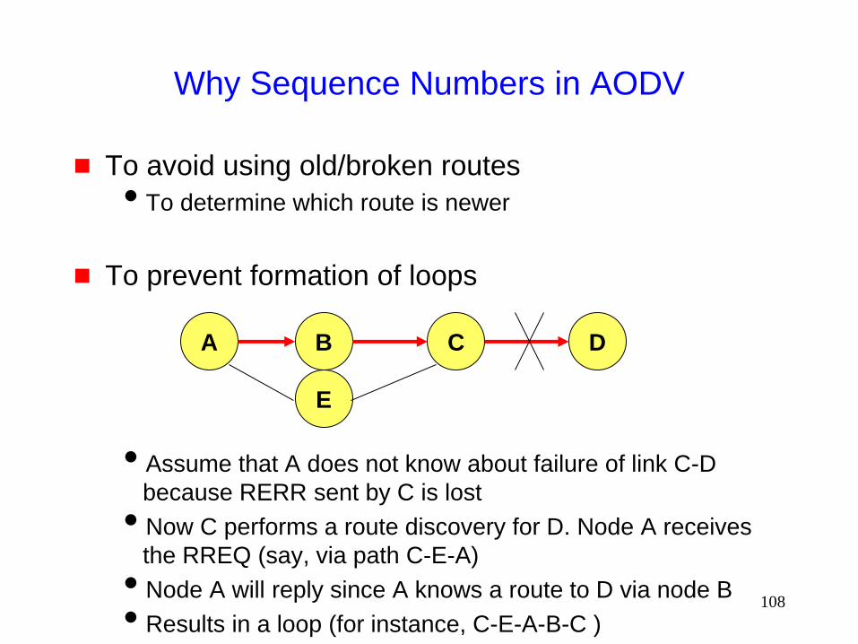
Why Sequence Numbers in AODV
To avoid using old/broken routes
To determine which route is newer
To prevent formation of loops
Assume that A does not know about failure of link C-D
because RERR sent by C is lost
Now C performs a route discovery for D. Node A receives
the RREQ (say, via path C-E-A)
Node A will reply since A knows a route to D via node B
Results in a loop (for instance, C-E-A-B-C )
A B C D
E
109
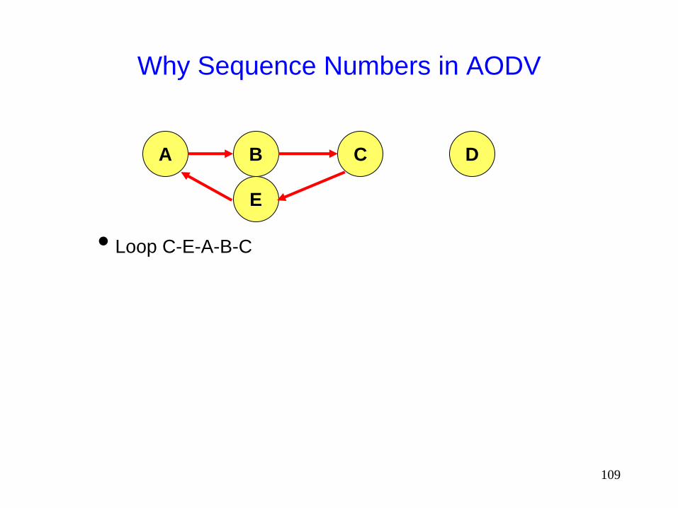
Why Sequence Numbers in AODV
Loop C-E-A-B-C
A B C D
E
110
Optimization: Expanding Ring Search
Route Requests are initially sent with small Time-to-
Live (TTL) field, to limit their propagation
DSR also includes a similar optimization
If no Route Reply is received, then larger TTL tried
111
Summary: AODV
Routes need not be included in packet headers
Nodes maintain routing tables containing entries only
for routes that are in active use
At most one next-hop per destination maintained at
each node
DSR may maintain several routes for a single destination
Unused routes expire even if topology does not
change

112
So far ...
All protocols discussed so far perform some form of
flooding
Now we will consider protocols which try to
reduce/avoid such behavior
113
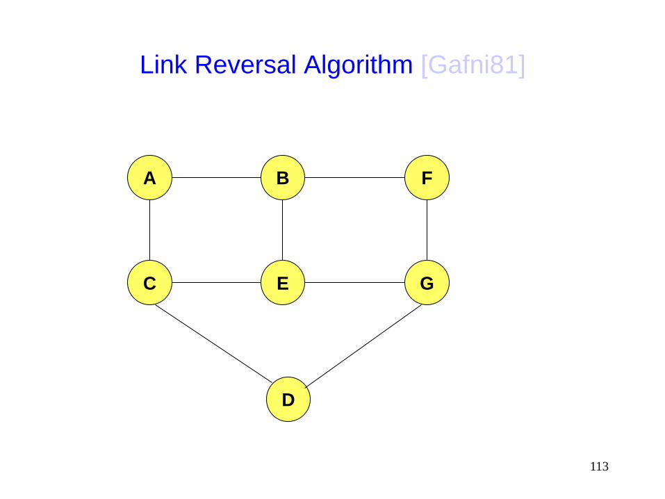
Link Reversal Algorithm [Gafni81]
A F B
C E G
D

114
Link Reversal Algorithm
A F B
C E G
D
Maintain a directed acyclic
graph (DAG) for each
destination, with the destination
being the only sink
This DAG is for destination
node D
Links are bi-directional
But algorithm imposes
logical directions on them
115
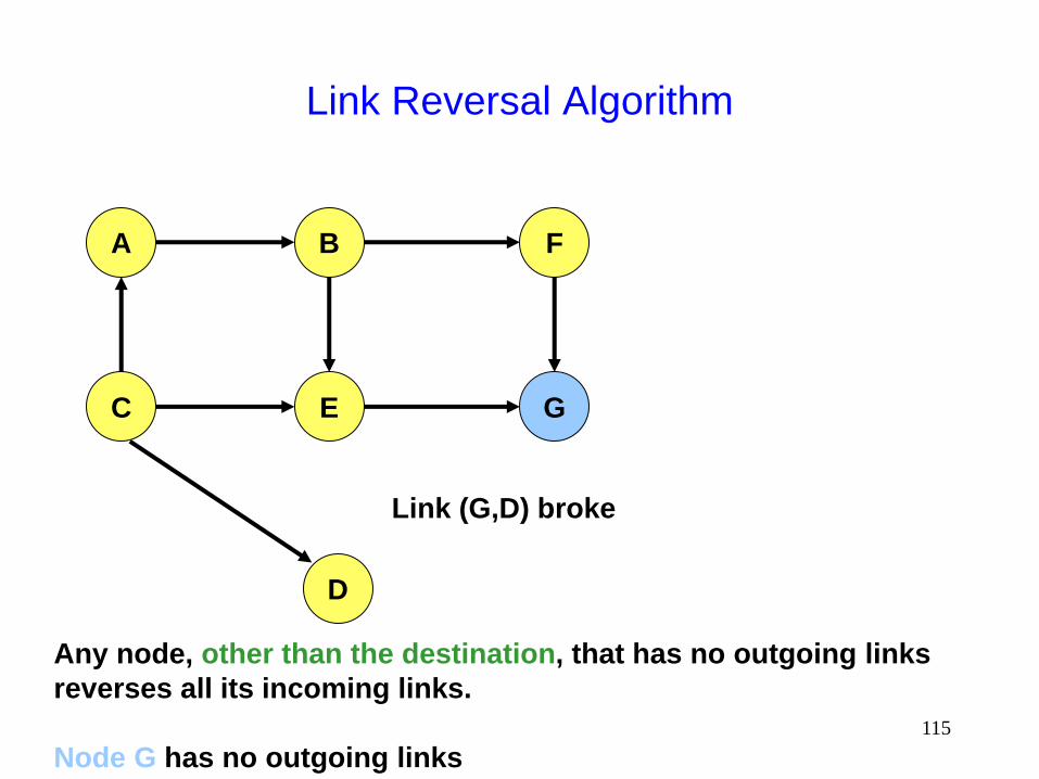
Link Reversal Algorithm
Link (G,D) broke
A F B
C E G
D
Any node, other than the destination, that has no outgoing links
reverses all its incoming links.
Node G has no outgoing links
116
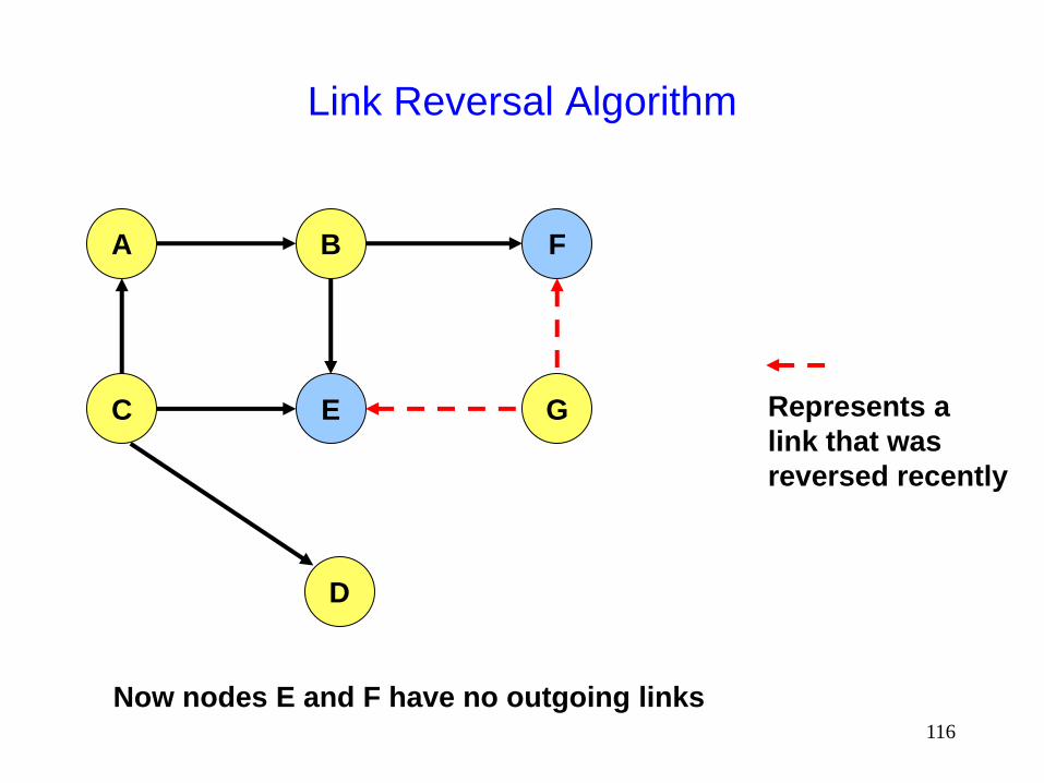
Link Reversal Algorithm
A F B
C E G
D
Now nodes E and F have no outgoing links
Represents a
link that was
reversed recently

117
Link Reversal Algorithm
A F B
C E G
D
Now nodes B and G have no outgoing links
Represents a
link that was
reversed recently
118
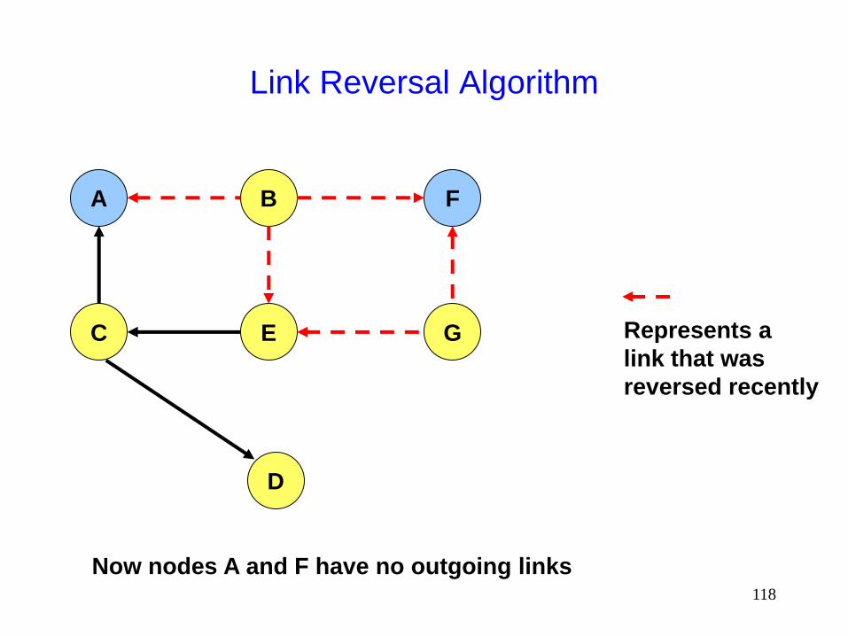
Link Reversal Algorithm
A F B
C E G
D
Now nodes A and F have no outgoing links
Represents a
link that was
reversed recently
119
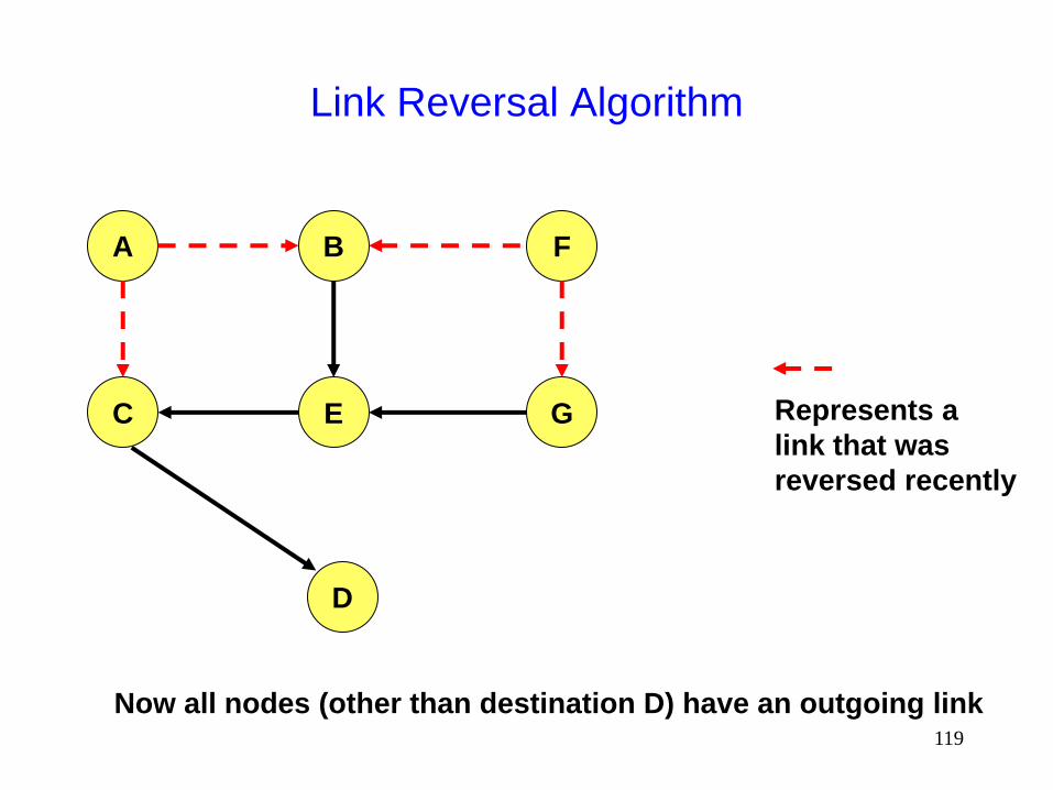
Link Reversal Algorithm
A F B
C E G
D
Now all nodes (other than destination D) have an outgoing link
Represents a
link that was
reversed recently

120
Link Reversal Algorithm
A F B
C E G
D
DAG has been restored with only the destination as a sink

121
Link Reversal Algorithm
Attempts to keep link reversals local to where the
failure occurred
But this is not guaranteed
When the first packet is sent to a destination, the
destination oriented DAG is constructed
The initial construction does result in flooding of
control packets

122
Link Reversal Algorithm
The previous algorithm is called a full reversal
method since when a node reverses links, it reverses
all its incoming links
Partial reversal method [Gafni81]: A node reverses
incoming links from only those neighbors who have
not themselves reversed links “previously”
If all neighbors have reversed links, then the node reverses
all its incoming links
“Previously” at node X means since the last link reversal
done by node X
123
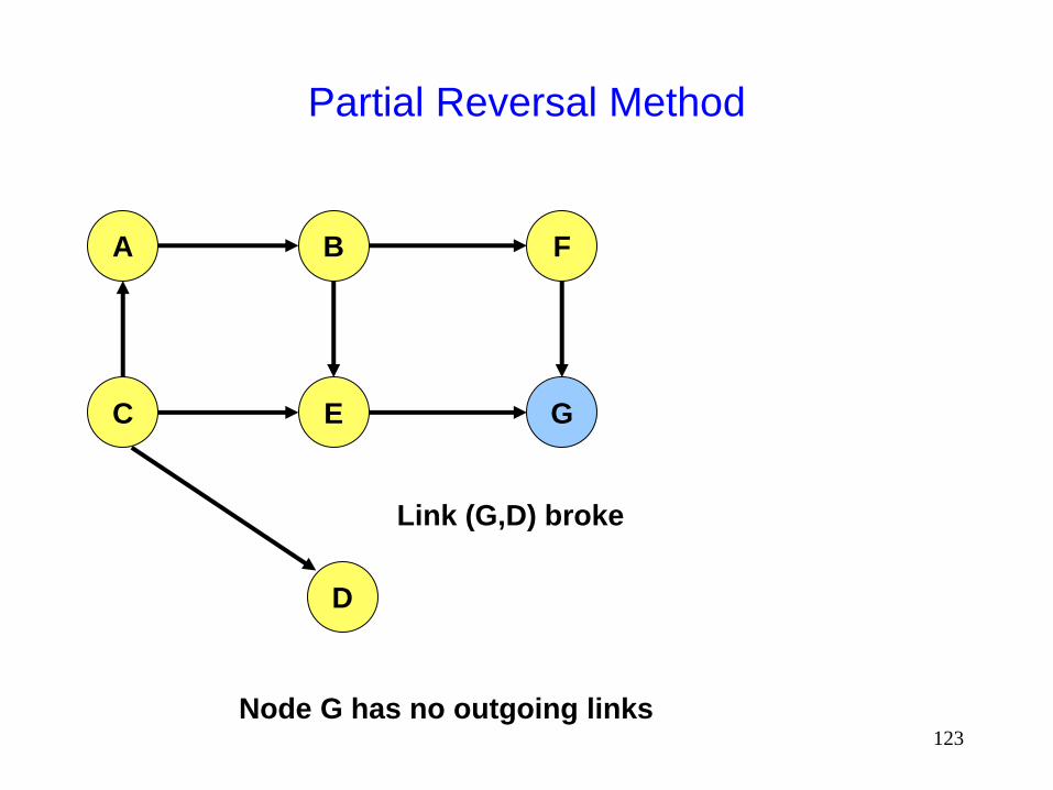
Partial Reversal Method
Link (G,D) broke
A F B
C E G
D
Node G has no outgoing links

124
Partial Reversal Method
A F B
C E G
D
Now nodes E and F have no outgoing links
Represents a
link that was
reversed recently
Represents a
node that has
reversed links

125
Partial Reversal Method
A F B
C E G
D
Nodes E and F do not reverse links from node G
Now node B has no outgoing links
Represents a
link that was
reversed recently

126
Partial Reversal Method
A F B
C E G
D
Now node A has no outgoing links
Represents a
link that was
reversed recently
127
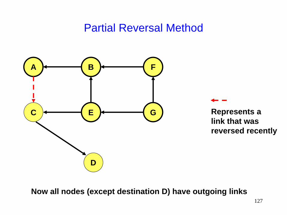
Partial Reversal Method
A F B
C E G
D
Now all nodes (except destination D) have outgoing links
Represents a
link that was
reversed recently
128
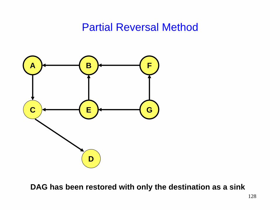
Partial Reversal Method
A F B
C E G
D
DAG has been restored with only the destination as a sink
129
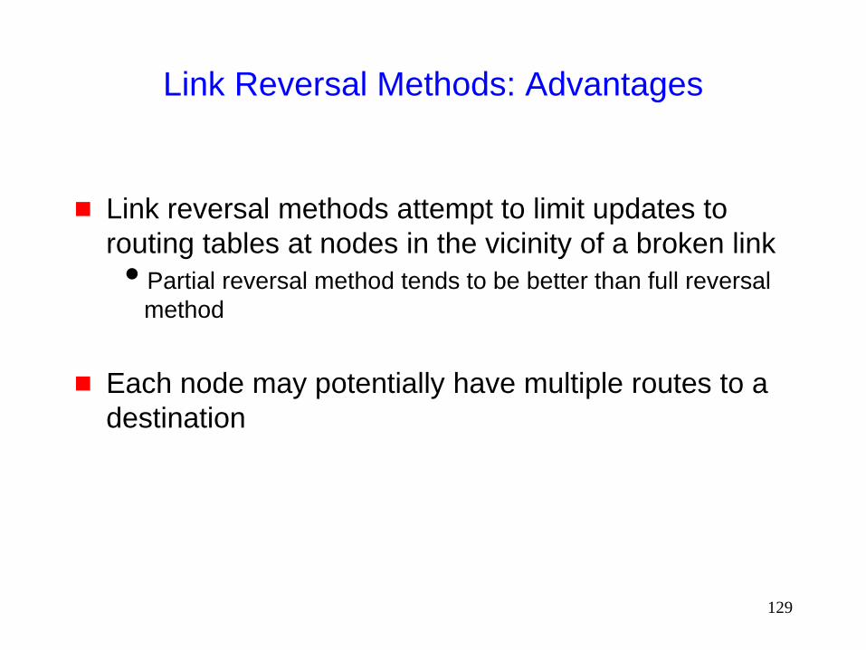
Link Reversal Methods: Advantages
Link reversal methods attempt to limit updates to
routing tables at nodes in the vicinity of a broken link
Partial reversal method tends to be better than full reversal
method
Each node may potentially have multiple routes to a
destination
130
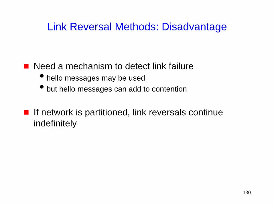
Link Reversal Methods: Disadvantage
Need a mechanism to detect link failure
hello messages may be used
but hello messages can add to contention
If network is partitioned, link reversals continue
indefinitely

131
Link Reversal in a Partitioned Network
A F B
C E G
D This DAG is for destination node D

132
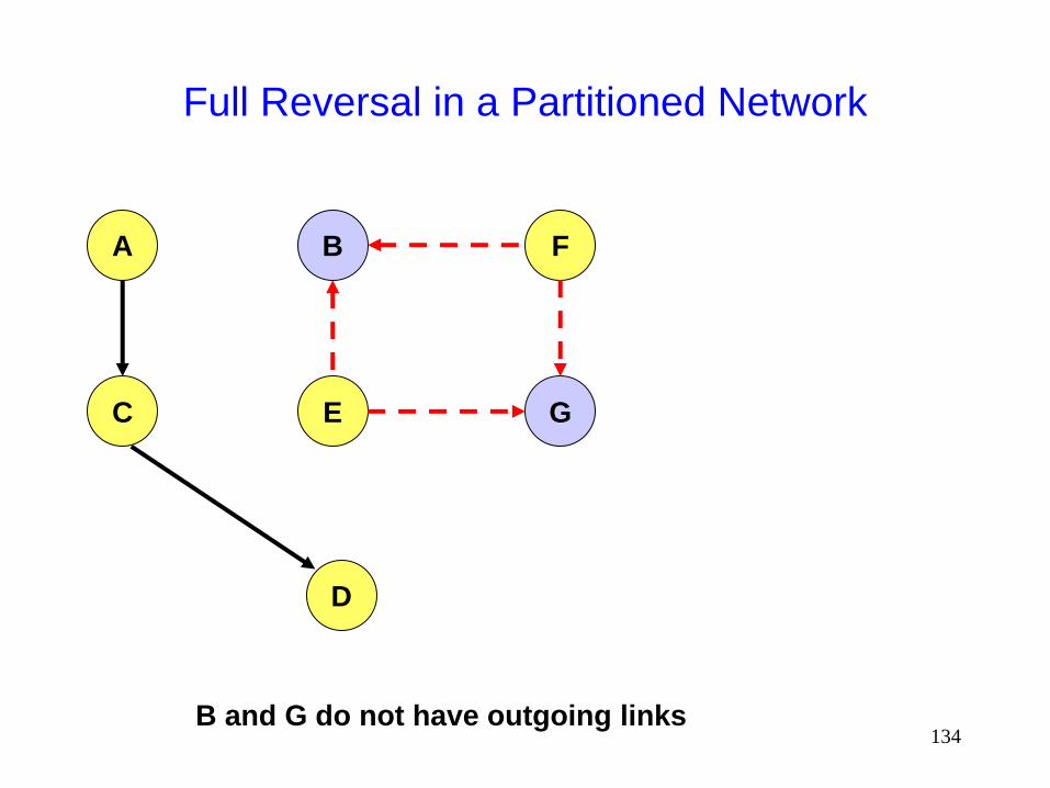
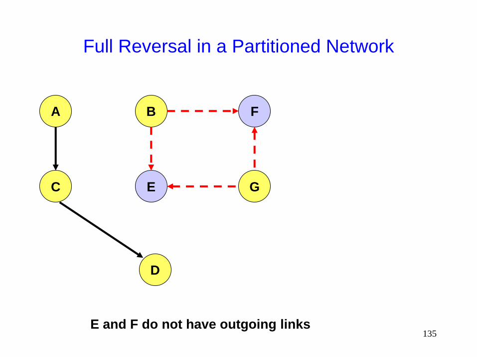
Full Reversal in a Partitioned Network
A F B
C E G
D
A and G do not have outgoing links

133
Full Reversal in a Partitioned Network
A F B
C E G
D
E and F do not have outgoing links
134
Full Reversal in a Partitioned Network
A F B
C E G
D
B and G do not have outgoing links
135
Full Reversal in a Partitioned Network
A F B
C E G
D
E and F do not have outgoing links

136
Full Reversal in a Partitioned Network
A F B
C E G
D
In the partition
disconnected from
destination D, link
reversals continue, until
the partitions merge
Need a mechanism to
minimize this wasteful
activity
Similar scenario can
occur with partial
reversal method too

137
Temporally-Ordered Routing Algorithm
(TORA) [Park97Infocom]
TORA modifies the partial link reversal method to be
able to detect partitions
When a partition is detected, all nodes in the partition
are informed, and link reversals in that partition cease
138
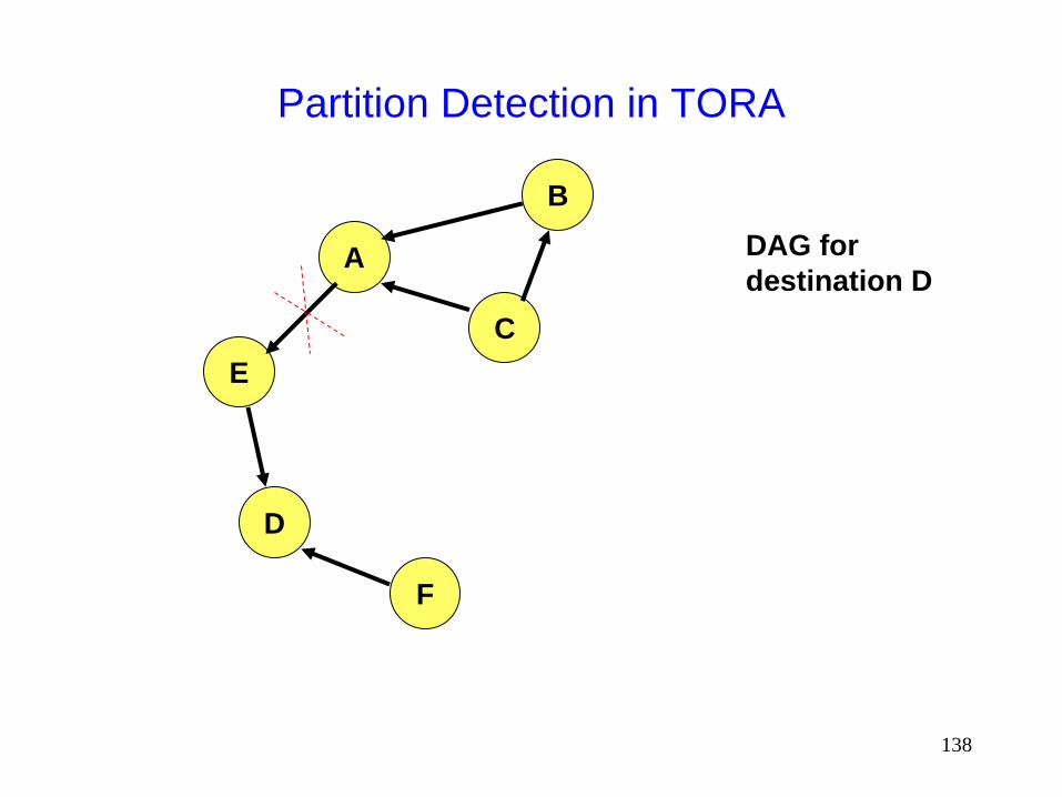
Partition Detection in TORA
A
B
E
D
F
C
DAG for
destination D
139
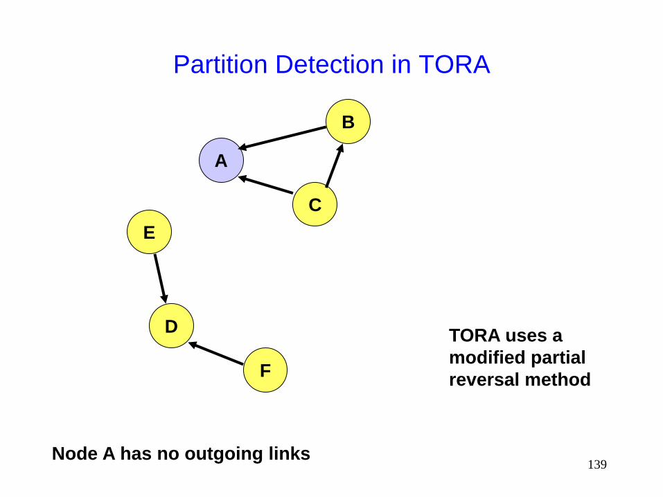
Partition Detection in TORA
A
B
E
D
F
C
TORA uses a
modified partial
reversal method
Node A has no outgoing links

140
Partition Detection in TORA
A
B
E
D
F
C
TORA uses a
modified partial
reversal method
Node B has no outgoing links

141
Partition Detection in TORA
A
B
E
D
F
C
Node B has no outgoing links

142
Partition Detection in TORA
A
B
E
D
F
C
Node C has no outgoing links -- all its neighbor have
reversed links previously.

143
Partition Detection in TORA
A
B
E
D
F
C
Nodes A and B receive the reflection from node C
Node B now has no outgoing link

144
Partition Detection in TORA
A
B
E
D
F
C
Node A has received the reflection from all its neighbors.
Node A determines that it is partitioned from destination D.
Node B propagates
the reflection to node A

145
Partition Detection in TORA
A
B
E
D
F
C On detecting a partition,
node A sends a clear (CLR)
message that purges all
directed links in that
partition

146
TORA
Improves on the partial link reversal method in
[Gafni81] by detecting partitions and stopping non-
productive link reversals
Paths may not be shortest
The DAG provides many hosts the ability to send
packets to a given destination
Beneficial when many hosts want to communicate with a
single destination
147
TORA Design Decision
TORA performs link reversals as dictated by [Gafni81]
However, when a link breaks, it looses its direction
When a link is repaired, it may not be assigned a direction, unless some node has performed a route discovery after the link broke if no one wants to send packets to D anymore, eventually,
the DAG for destination D may disappear
TORA makes effort to maintain the DAG for D only if someone needs route to D Reactive behavior
148
TORA Design Decision
One proposal for modifying TORA optionally allowed a more proactive behavior, such that a DAG would be maintained even if no node is attempting to transmit to the destination
Moral of the story: The link reversal algorithm in [Gafni81] does not dictate a proactive or reactive response to link failure/repair
Decision on reactive/proactive behavior should be made based on environment under consideration
149
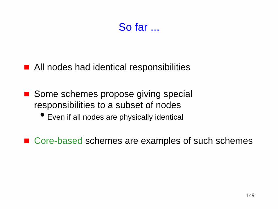
So far ...
All nodes had identical responsibilities
Some schemes propose giving special
responsibilities to a subset of nodes
Even if all nodes are physically identical
Core-based schemes are examples of such schemes
150
Asymmetric Responsibilities

151
Core-Extraction Distributed Ad Hoc Routing
(CEDAR) [Sivakumar99]
A subset of nodes in the network is identified as the core
Each node in the network must be adjacent to at least one node in the core Each node picks one core node as its dominator (or leader)
Core is determined by periodic message exchanges between each node and its neighbors attempt made to keep the number of nodes in the core small
Each core node determines paths to nearby core nodes by means of a localized broadcast Each core node guaranteed to have a core node at <=3 hops

152
CEDAR: Core Nodes
B
A
C E
J S K
D
F
H
G
A core node
Node E is the dominator
for nodes D, F and K
153
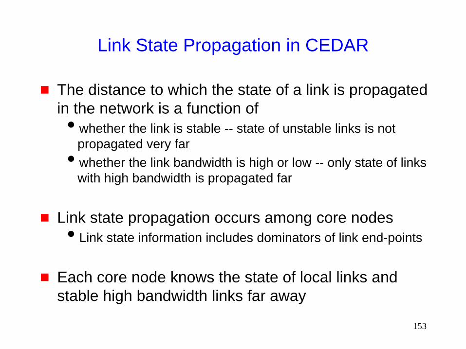
Link State Propagation in CEDAR
The distance to which the state of a link is propagated
in the network is a function of
whether the link is stable -- state of unstable links is not
propagated very far
whether the link bandwidth is high or low -- only state of links
with high bandwidth is propagated far
Link state propagation occurs among core nodes
Link state information includes dominators of link end-points
Each core node knows the state of local links and
stable high bandwidth links far away

154
Route Discovery in CEDAR
When a node S wants to send packets to destination D
Node S informs its dominator core node B
Node B finds a route in the core network to the core node E which is the dominator for destination D This is done by means of a DSR-like route discovery (but
somewhat optimized) process among the core nodes
Core nodes on the above route then build a route from S to D using locally available link state information
Route from S to D may or may not include core nodes
155
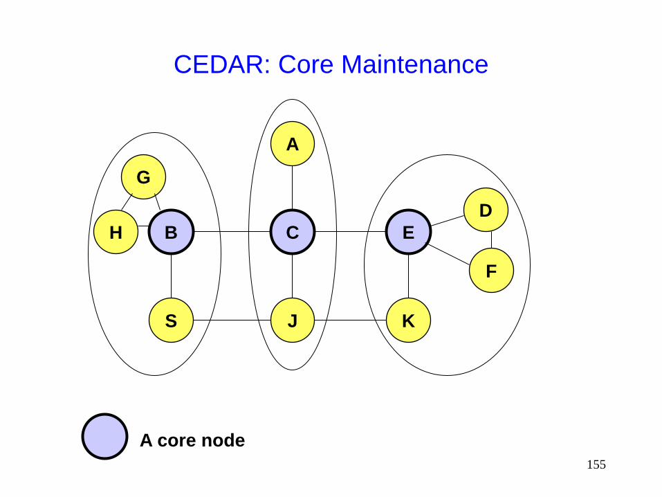
CEDAR: Core Maintenance
B
A
C E
J S K
D
F
H
G
A core node
156
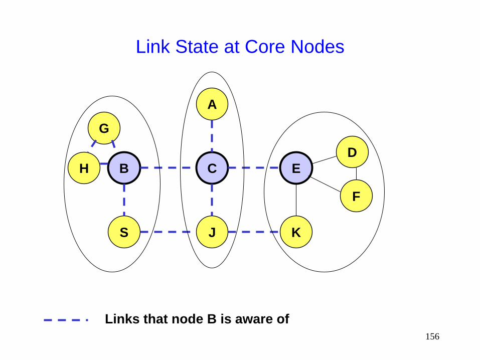
Link State at Core Nodes
B
A
C E
J S K
D
F
H
G
Links that node B is aware of

157
CEDAR Route Discovery
B
A
C E
J S K
D
F
H
G
Partial route constructed by B
Links that node C is aware of

158
CEDAR Route Discovery
B
A
C E
J S K
D
F
H
G
Complete route -- last two hops determined by node C

159
CEDAR
Advantages
Route discovery/maintenance duties limited to a small
number of core nodes
Link state propagation a function of link stability/quality
Disadvantages
Core nodes have to handle additional traffic, associated with
route discovery and maintenance

160
Asymmetric Responsibilities:
Cluster-Based Schemes
Some cluster-based schemes have also been
proposed [Gerla95,Krishna97,Amis00]
In some cluster-based schemes, a leader is elected
for each cluster of node
The leader often has some special responsibilities
Different schemes may differ in
how clusters are determined
the way cluster head (leader) is chosen
duties assigned to the cluster head

161
Proactive Protocols
Most of the schemes discussed so far are reactive
Proactive schemes based on distance-vector and
link-state mechanisms have also been proposed

162
Link State Routing [Huitema95]
Each node periodically floods status of its links
Each node re-broadcasts link state information received from its neighbor
Each node keeps track of link state information received from other nodes
Each node uses above information to determine next hop to each destination

163
Optimized Link State Routing (OLSR)
[Jacquet00ietf,Jacquet99Inria]
The overhead of flooding link state information is
reduced by requiring fewer nodes to forward the
information
A broadcast from node X is only forwarded by its
multipoint relays
Multipoint relays of node X are its neighbors such
that each two-hop neighbor of X is a one-hop
neighbor of at least one multipoint relay of X
Each node transmits its neighbor list in periodic beacons, so
that all nodes can know their 2-hop neighbors, in order to
choose the multipoint relays
164
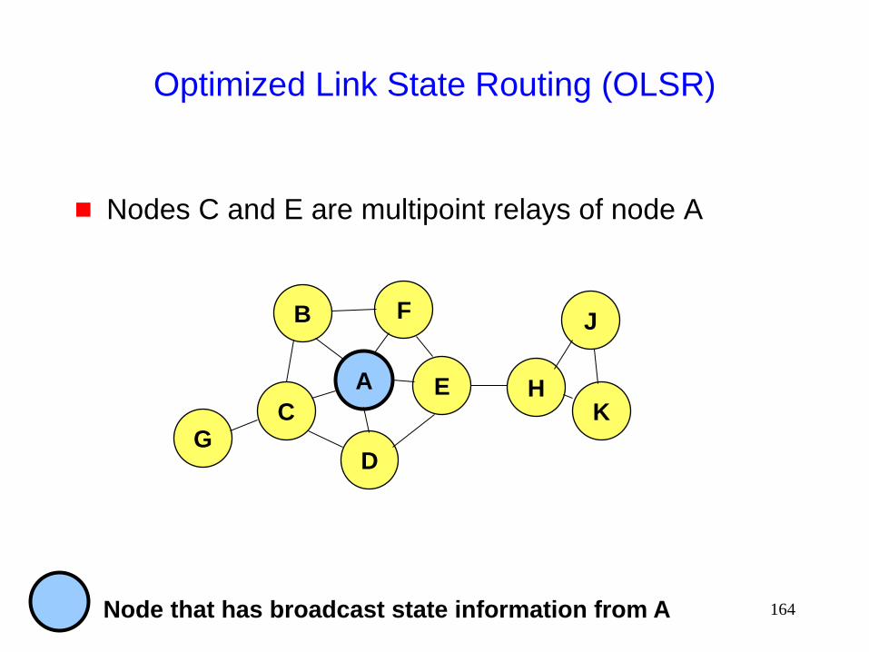
Optimized Link State Routing (OLSR)
Nodes C and E are multipoint relays of node A
A
B F
C
D
E H
G K
J
Node that has broadcast state information from A

165
Optimized Link State Routing (OLSR)
Nodes C and E forward information received from A
A
B F
C
D
E H
G K
J
Node that has broadcast state information from A

166
Optimized Link State Routing (OLSR)
Nodes E and K are multipoint relays for node H
Node K forwards information received from H
E has already forwarded the same information once
A
B F
C
D
E H
G K
J
Node that has broadcast state information from A

167
OLSR
OLSR floods information through the multipoint relays
The flooded itself is fir links connecting nodes to
respective multipoint relays
Routes used by OLSR only include multipoint relays
as intermediate nodes

168
Destination-Sequenced Distance-Vector
(DSDV) [Perkins94Sigcomm]
Each node maintains a routing table which stores
next hop towards each destination
a cost metric for the path to each destination
a destination sequence number that is created by the
destination itself
Sequence numbers used to avoid formation of loops
Each node periodically forwards the routing table to
its neighbors
Each node increments and appends its sequence number
when sending its local routing table
This sequence number will be attached to route entries
created for this node

169
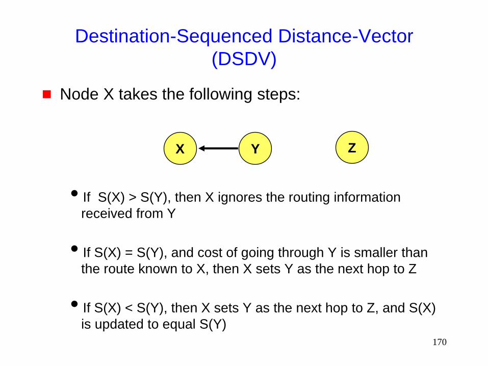
Destination-Sequenced Distance-Vector
(DSDV)
Assume that node X receives routing information
from Y about a route to node Z
Let S(X) and S(Y) denote the destination sequence
number for node Z as stored at node X, and as sent
by node Y with its routing table to node X,
respectively
X Y Z
170
Destination-Sequenced Distance-Vector
(DSDV)
Node X takes the following steps:
If S(X) > S(Y), then X ignores the routing information
received from Y
If S(X) = S(Y), and cost of going through Y is smaller than
the route known to X, then X sets Y as the next hop to Z
If S(X) < S(Y), then X sets Y as the next hop to Z, and S(X)
is updated to equal S(Y)
X Y Z

171
Hybrid Protocols
172
Zone Routing Protocol (ZRP) [Haas98]
Zone routing protocol combines
Proactive protocol: which pro-actively updates
network state and maintains route regardless of
whether any data traffic exists or not
Reactive protocol: which only determines route to a
destination if there is some data to be sent to the
destination
173
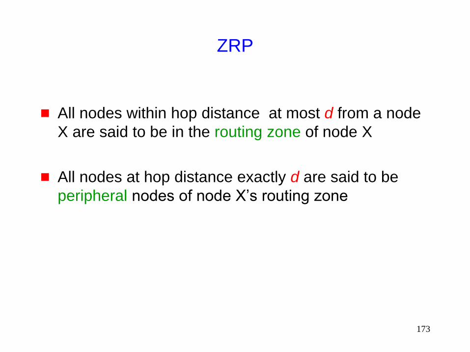
ZRP
All nodes within hop distance at most d from a node
X are said to be in the routing zone of node X
All nodes at hop distance exactly d are said to be
peripheral nodes of node X’s routing zone
174
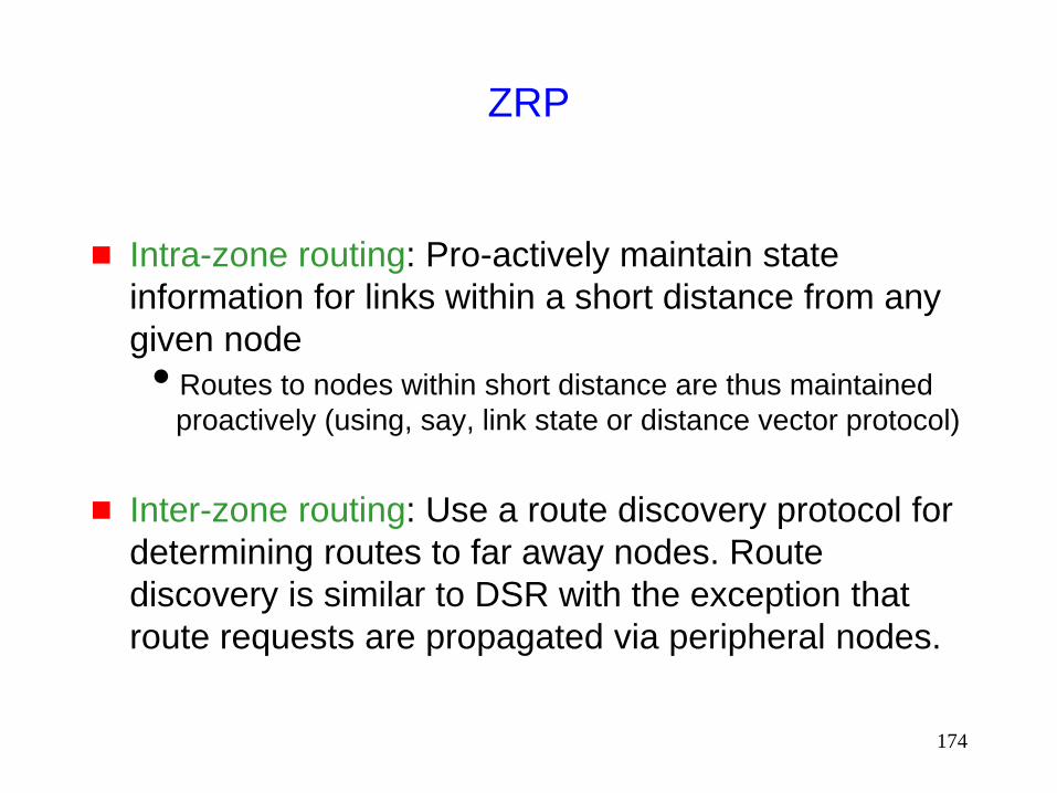
ZRP
Intra-zone routing: Pro-actively maintain state
information for links within a short distance from any
given node
Routes to nodes within short distance are thus maintained
proactively (using, say, link state or distance vector protocol)
Inter-zone routing: Use a route discovery protocol for
determining routes to far away nodes. Route
discovery is similar to DSR with the exception that
route requests are propagated via peripheral nodes.

175
ZRP: Example with
Zone Radius = d = 2
S C A
E F
B
D
S performs route
discovery for D
Denotes route request
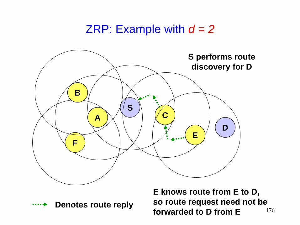
176
ZRP: Example with d = 2
S C A
E F
B
D
S performs route
discovery for D
Denotes route reply
E knows route from E to D,
so route request need not be
forwarded to D from E

177
ZRP: Example with d = 2
S C A
E F
B
D
S performs route
discovery for D
Denotes route taken by Data

178
Landmark Routing (LANMAR) for MANET with
Group Mobility [Pei00Mobihoc]
A landmark node is elected for a group of nodes that
are likely to move together
A scope is defined such that each node would
typically be within the scope of its landmark node
Each node propagates link state information
corresponding only to nodes within it scope and
distance-vector information for all landmark nodes
Combination of link-state and distance-vector
Distance-vector used for landmark nodes outside the scope
No state information for non-landmark nodes outside scope
maintained
179
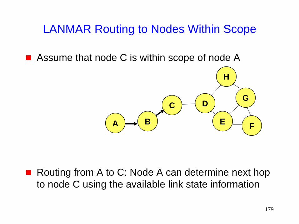
LANMAR Routing to Nodes Within Scope
Assume that node C is within scope of node A
Routing from A to C: Node A can determine next hop
to node C using the available link state information
A B
C
F
H
G
E
D

180
LANMAR Routing to Nodes Outside Scope
Routing from node A to F which is outside A’s scope
Let H be the landmark node for node F
Node A somehow knows that H is the landmark for C
Node A can determine next hop to node H using the available distance vector information
A B
C
F
H
G
E
D
181
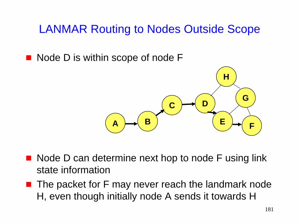
LANMAR Routing to Nodes Outside Scope
Node D is within scope of node F
Node D can determine next hop to node F using link
state information
The packet for F may never reach the landmark node
H, even though initially node A sends it towards H
A B
C
F
H
G
E
D
182
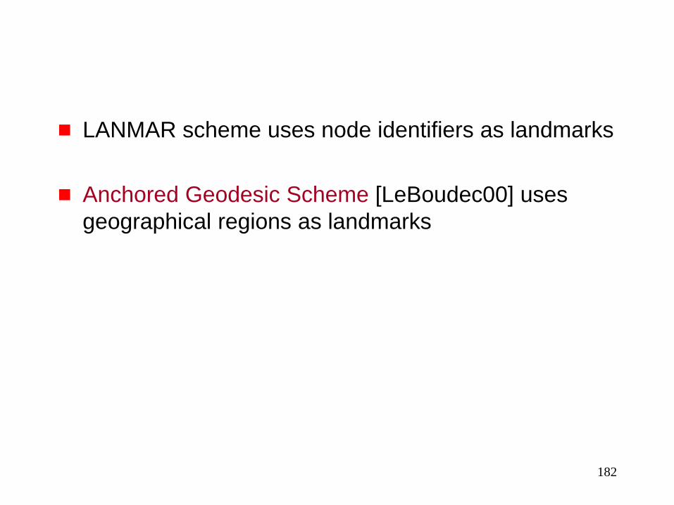
LANMAR scheme uses node identifiers as landmarks
Anchored Geodesic Scheme [LeBoudec00] uses
geographical regions as landmarks
183
Geodesic Routing Without Anchors
[Blazevic00,Hubaux00wcnc]
Each node somehow keeps track of routes to nodes
within its zone (intra-zone routing)
Each node also records physical locations of nodes
on its zone boundary
Inter-zone routing: When a packet is to be routed to
someone outside the zone, the packet is sent to a
zone-boundary node in the direction of the
destination
The packet is forwarded in this manner until it
reaches someone within the destination’s zone
This node then uses intra-zone routing to deliver the
packet
Similar to the GEDIR protocol [Lin98]
184
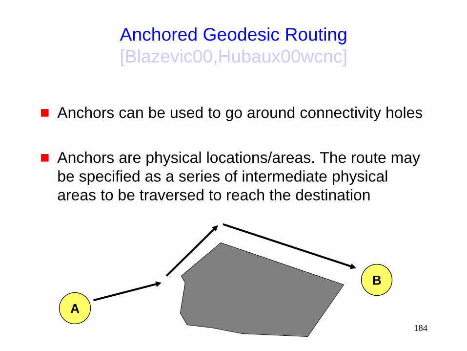
Anchored Geodesic Routing
[Blazevic00,Hubaux00wcnc]
Anchors can be used to go around connectivity holes
Anchors are physical locations/areas. The route may
be specified as a series of intermediate physical
areas to be traversed to reach the destination
B
A

185
Routing
Protocols discussed so far find/maintain a route
provided it exists
Some protocols attempt to ensure that a route exists
by
Power Control [Ramanathan00Infocom]
Limiting movement of hosts or forcing them to take detours
[Reuben98thesis]

186
Power Control
Protocols discussed so far find a route, on a given network topology
Some researchers propose controlling network topology by transmission power control to yield network properties which may be desirable [Ramanathan00Infocom]
Such approaches can significantly impact performance at several layers of protocol stack
[Wattwnhofer00Infocom] provides a distributed mechanism for power control which allows for local decisions, but guarantees global connectivity
Each node uses a power level that ensures that the node has at least one neighbor in each cone with angle 2p/3

187
Other Routing Protocols
Plenty of other routing protocols
Discussion here is far from exhaustive
Many of the existing protocols could potentially be
adapted for MANET (some have already been
adapted as discussed earlier)

188
Some Variations

189
Power-Aware Routing
[Singh98Mobicom,Chang00Infocom]
Define optimization criteria as a function of energy
consumption. Examples:
Minimize energy consumed per packet
Minimize time to network partition due to energy
depletion
Maximize duration before a node fails due to energy
depletion
190
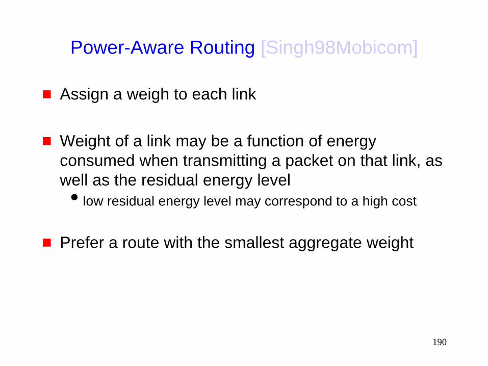
Power-Aware Routing [Singh98Mobicom]
Assign a weigh to each link
Weight of a link may be a function of energy
consumed when transmitting a packet on that link, as
well as the residual energy level
low residual energy level may correspond to a high cost
Prefer a route with the smallest aggregate weight
191
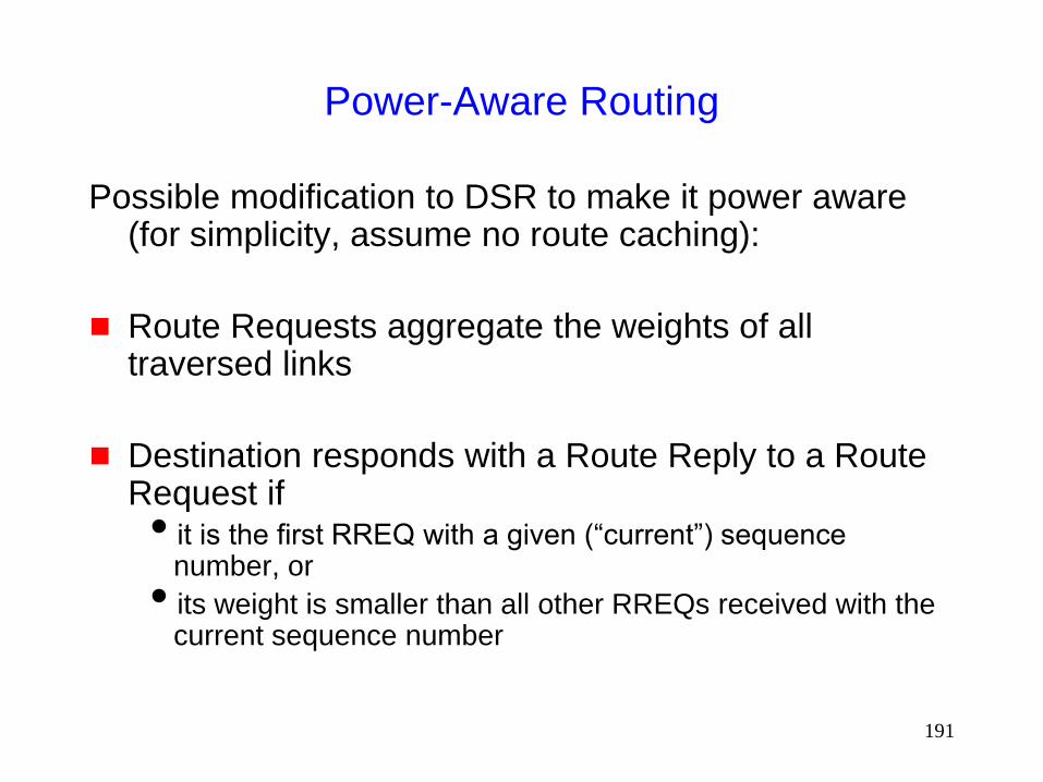
Power-Aware Routing
Possible modification to DSR to make it power aware (for simplicity, assume no route caching):
Route Requests aggregate the weights of all traversed links
Destination responds with a Route Reply to a Route Request if it is the first RREQ with a given (“current”) sequence
number, or
its weight is smaller than all other RREQs received with the current sequence number

192
Signal Stability Based Adaptive Routing (SSA)
[Dube97]
Similar to DSR
A node X re-broadcasts a Route Request received from Y only if the (X,Y) link is deemed to have a strong signal stability
Signal stability is evaluated as a moving average of the signal strength of packets received on the link in recent past
An alternative approach would be to assign a cost as a function of signal stability
193
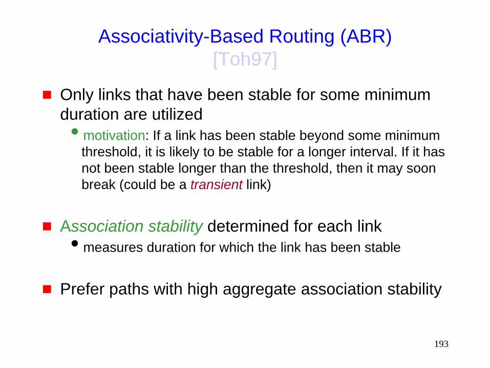
Associativity-Based Routing (ABR)
[Toh97]
Only links that have been stable for some minimum
duration are utilized
motivation: If a link has been stable beyond some minimum
threshold, it is likely to be stable for a longer interval. If it has
not been stable longer than the threshold, then it may soon
break (could be a transient link)
Association stability determined for each link
measures duration for which the link has been stable
Prefer paths with high aggregate association stability

194
Geography Adaptive Fidelity [Xu01MobiCom]
Each node associates itself with a square in a virtual
grid
Node in each grid square coordinate to determine
who will sleep and how long

195
Preemptive Routing [Goff01MobiCom]
Add some proactivity to reactive routing protocols
such as DSR and AODV
Route discovery initiated when it appears that an
active route will break in the near future
Initiating route discover before existing route breaks
reduces discovery latency

196
QoS Routing

197
Quality-of-Service
Several proposals for reserving bandwidth for a flow
in MANET
Due to lack of time, these are not being discussed in
this tutorial

198
Performance of Unicast Routing in MANET
Several performance comparisons [Broch98Mobicom,Johansson99Mobicom,Das00Infocom,
Das98ic3n]
We will discuss performance issue later in the tutorial

199
Multicasting
in
Mobile Ad Hoc Networks
200
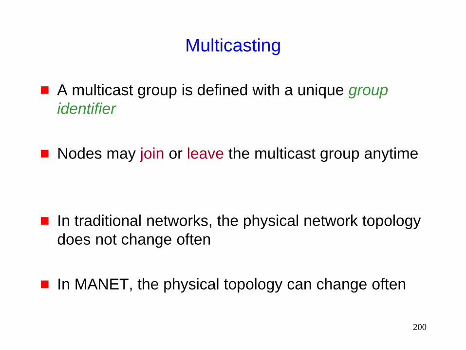
Multicasting
A multicast group is defined with a unique group
identifier
Nodes may join or leave the multicast group anytime
In traditional networks, the physical network topology
does not change often
In MANET, the physical topology can change often

201
Multicasting in MANET
Need to take topology change into account when
designing a multicast protocol
Several new protocols have been proposed for
multicasting in MANET
202
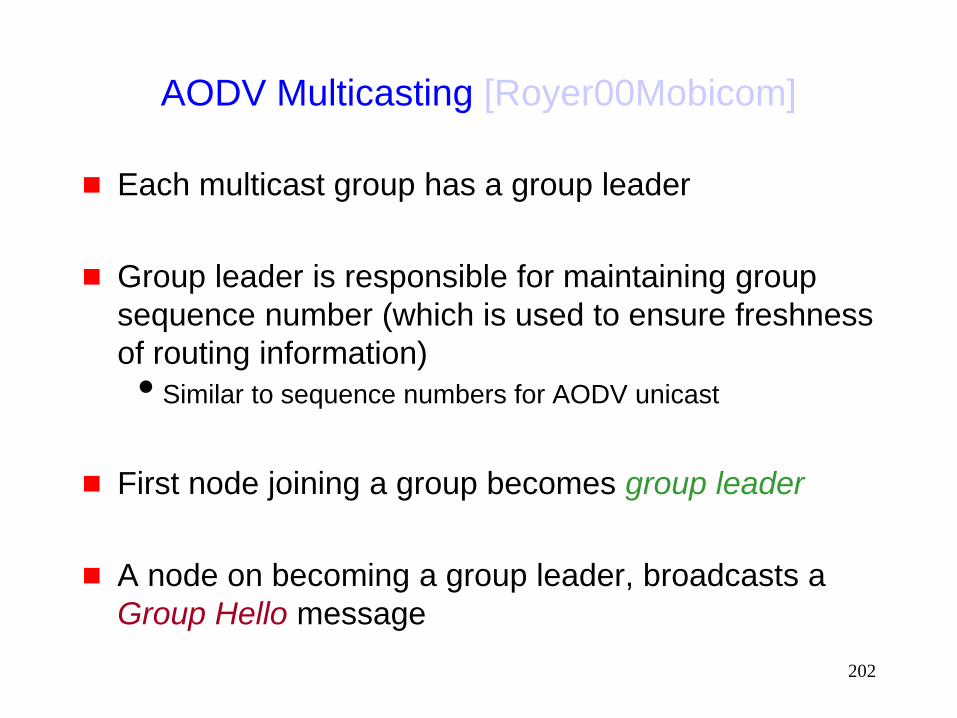
AODV Multicasting [Royer00Mobicom]
Each multicast group has a group leader
Group leader is responsible for maintaining group
sequence number (which is used to ensure freshness
of routing information)
Similar to sequence numbers for AODV unicast
First node joining a group becomes group leader
A node on becoming a group leader, broadcasts a
Group Hello message

203
AODV Group Sequence Number
In our illustrations, we will ignore the group sequence
numbers
However, note that a node makes use of information
received only with recent enough sequence number

204
AODV Multicast Tree
E
L
H
J
D
C
G
A
K
N Group and multicast tree member
Tree (but not group) member
Group leader
B
Multicast tree links

205
Joining the Multicast Tree: AODV
E
L
H
J
D
C
G
A
K
N
Group leader
B N wishes to
join the group:
it floods RREQ
Route Request (RREQ)

206
Joining the Multicast Tree: AODV
E
L
H
J
D
C
G
A
K
N
Group leader
B N wishes to
join the group
Route Reply (RREP)

207
Joining the Multicast Tree: AODV
E
L
H
J
D
C
G
A
K
N
Group leader
B N wishes to
join the group
Multicast Activation (MACT)

208
Joining the Multicast Tree: AODV
E
L
H
J
D
C
G
A
K
N
Group leader
B N has joined
the group
Multicast tree links
Group member
Tree (but not group) member

209
Sending Data on the Multicast Tree
Data is delivered along the tree edges maintained by
the Multicast AODV algorithm
If a node which does not belong to the multicast
group wishes to multicast a packet
It sends a non-join RREQ which is treated similar in many
ways to RREQ for joining the group
As a result, the sender finds a route to a multicast group
member
Once data is delivered to this group member, the data is
delivered to remaining members along multicast tree edges

210
Leaving a Multicast Tree: AODV
E
L
H
J
D
C
G
A
Group leader
B
J wishes to
leave the group
Multicast tree links
K
N

211
Leaving a Multicast Tree: AODV
E
L
H
J
D
C
G
A
Group leader
B
J has left
the group
Since J is not a leaf
node, it must remain
a tree member
K
N
212
Leaving a Multicast Tree: AODV
E
L
H
J
D
C
G
A
Group leader
B
K
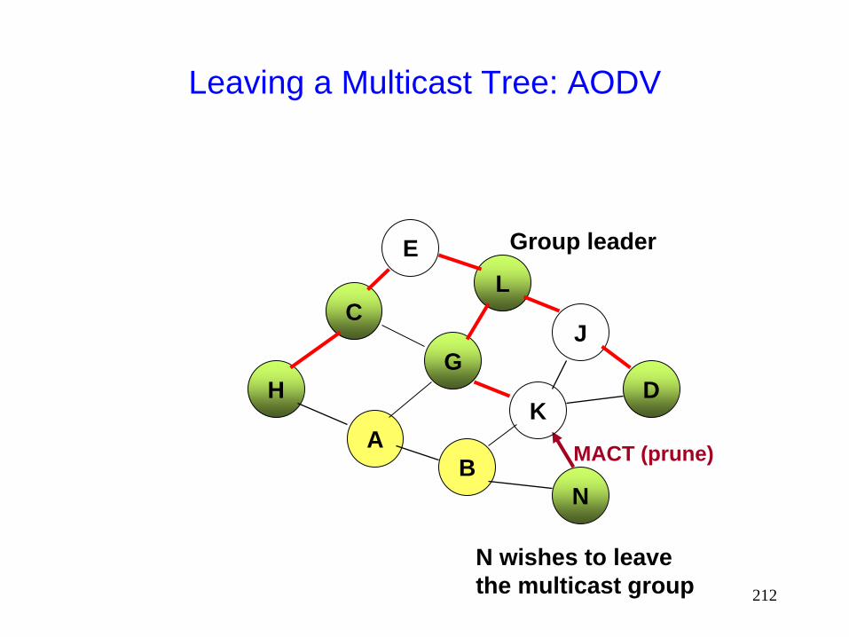
N
N wishes to leave
the multicast group
MACT (prune)
213
Leaving a Multicast Tree: AODV
E
L
H
J
D
C
G
A
Group leader
B
K
N
MACT
(prune)
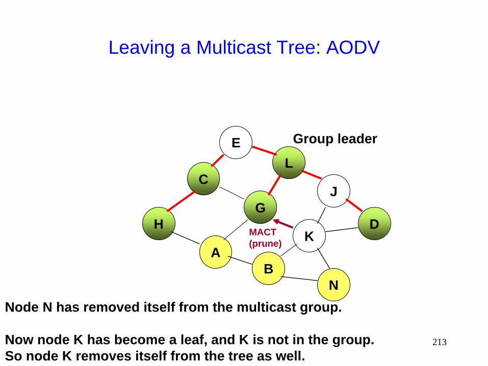
Node N has removed itself from the multicast group.
Now node K has become a leaf, and K is not in the group.
So node K removes itself from the tree as well.
214
Leaving a Multicast Tree: AODV
E
L
H
J
D
C
G
A
Group leader
B
K
N
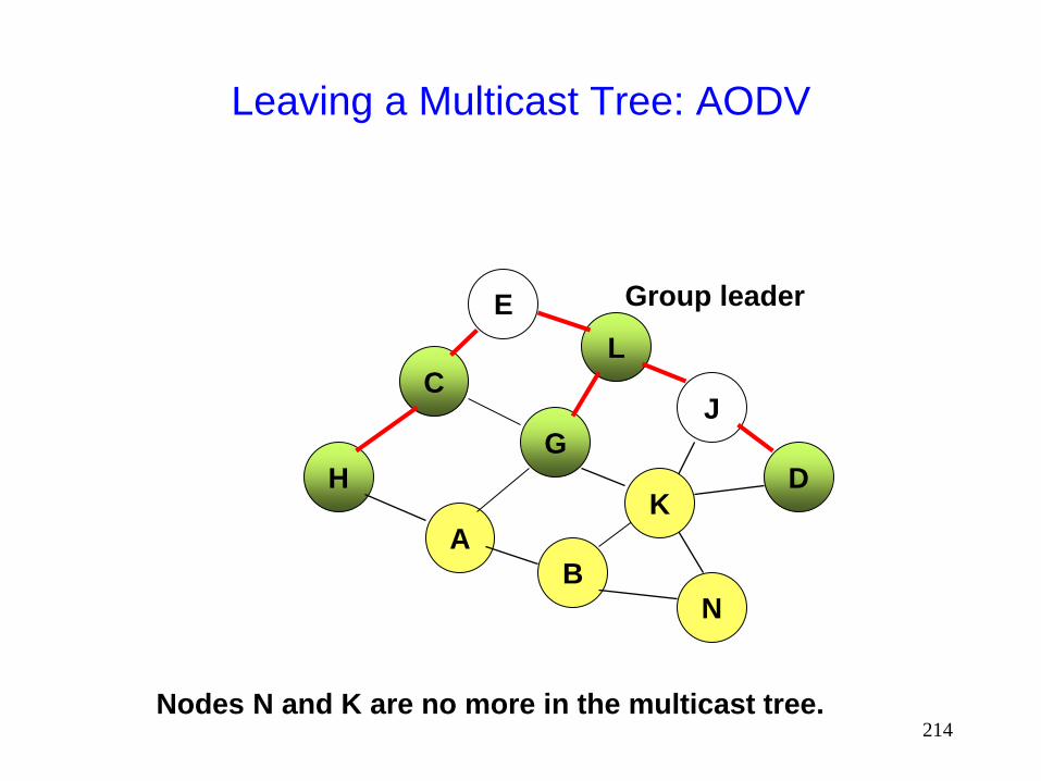
Nodes N and K are no more in the multicast tree.
215
Handling a Link Failure: AODV Multicasting
When a link (X,Y) on the multicast tree breaks, the
node that is further away from the leader is
responsible to reconstruct the tree, say node X
Node X, which is further downstream, transmits a
Route Request (RREQ)
Only nodes which are closer to the leader than node X’s last
known distance are allowed to send RREP in response to
the RREQ, to prevent nodes that are further downstream
from node X from responding
216
Handling Partitions: AODV
When failure of link (X,Y) results in a partition, the
downstream node, say X, initiates Route Request
If a Route Reply is not received in response, then
node X assumes that it is partitioned from the group
leader
A new group leader is chosen in the partition
containing node X
If node X is a multicast group member, it becomes
the group leader, else a group member downstream
from X is chosen as the group leader

217
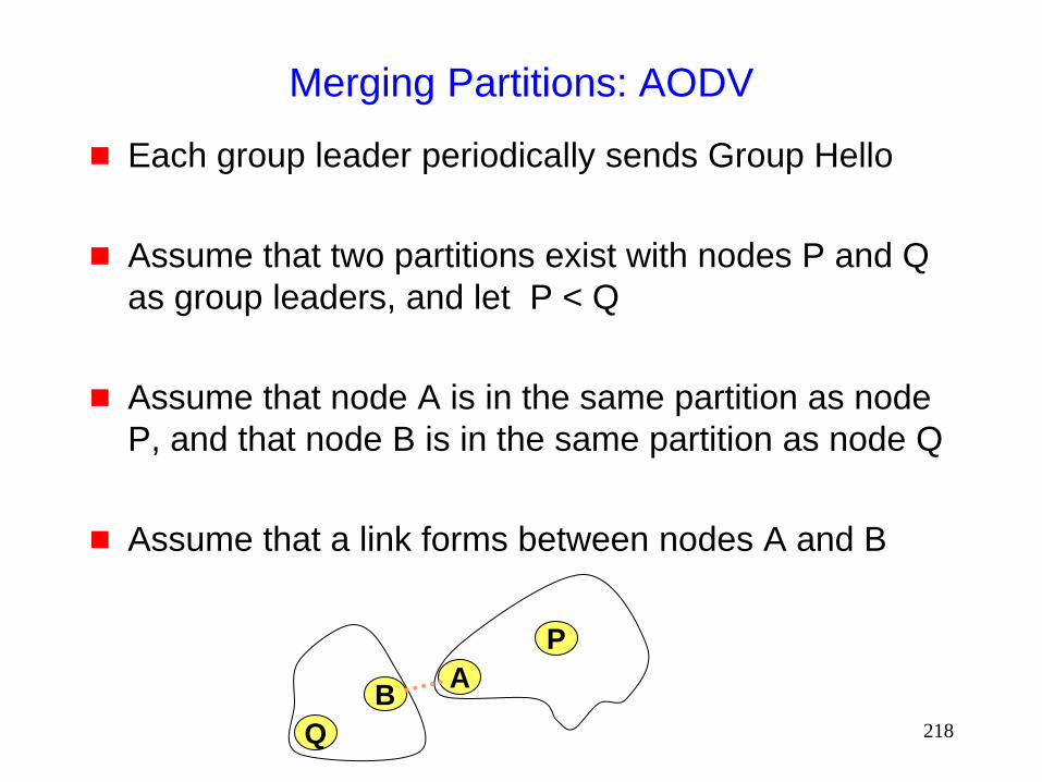
Merging Partitions: AODV
If the network is partitioned, then each partition has
its own group leader
When two partitions merge, group leader from one of
the two partitions is chosen as the leader for the
merged network
The leader with the larger identifier remains group leader
218
Merging Partitions: AODV
Each group leader periodically sends Group Hello
Assume that two partitions exist with nodes P and Q
as group leaders, and let P < Q
Assume that node A is in the same partition as node
P, and that node B is in the same partition as node Q
Assume that a link forms between nodes A and B
A
P
Q
B
219
Merging Partitions: AODV
Assume that node A receives Group Hello originated
by node Q through its new neighbor B
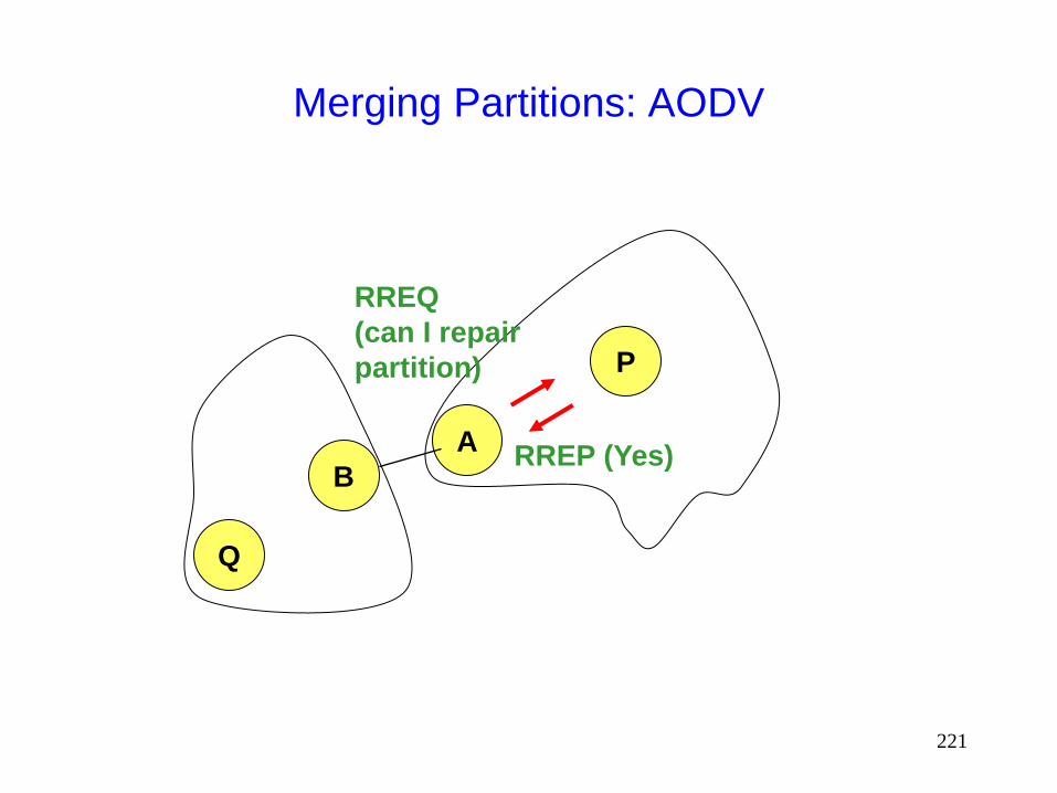
Node A asks exclusive permission from its leader P
to merge the two trees using a special Route
Request
Node A sends a special Route Request to node Q
Node Q then sends a Group Hello message (with a
special flag)
All tree nodes receiving this Group Hello record Q as
the leader
220
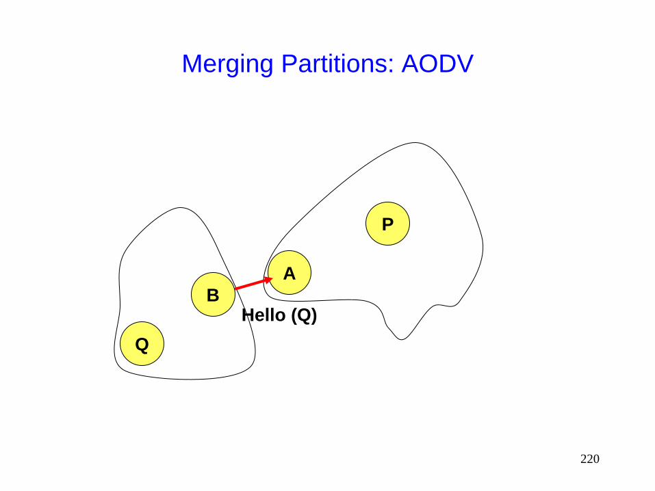
Merging Partitions: AODV
A
P
Q
B Hello (Q)
221
Merging Partitions: AODV
A
P
Q
B
RREQ
(can I repair
partition)
RREP (Yes)

222
Merging Partitions: AODV
A
P
Q
B RREQ (repair)

223
Merging Partitions: AODV
A
P
Q
B Group Hello
(update)
Q becomes leader of the merged multicast tree
New group sequence number is larger than most
recent ones known to P and Q both
224
Summary: Multicast AODV
Similar to unicast AODV
Uses leaders to maintain group sequence numbers,
and to help in tree maintenance

225
On-Demand Multicast Routing Protocol
(ODMRP)
ODMRP requires cooperation of nodes wishing to
send data to the multicast group
To construct the multicast mesh
A sender node wishing to send multicast packets
periodically floods a Join Data packet throughput the
network
Periodic transmissions are used to update the routes
226
On-Demand Multicast Routing Protocol
(ODMRP)
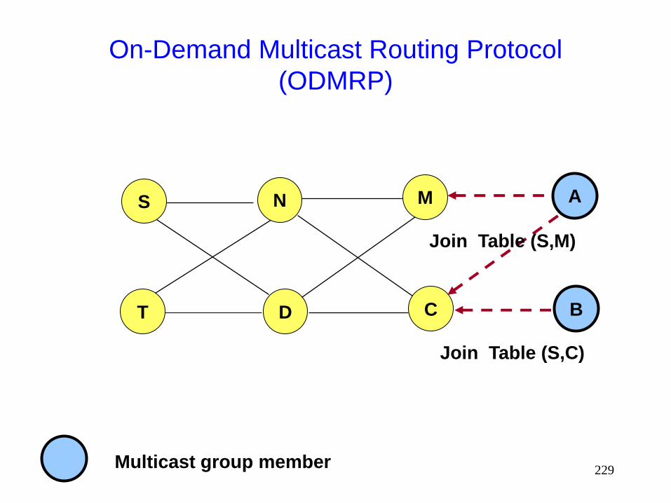
Each multicast group member on receiving a Join
Data, broadcasts a Join Table to all its neighbors
Join Table contains (sender S, next node N) pairs
next node N denotes the next node on the path from the
group member to the multicast sender S
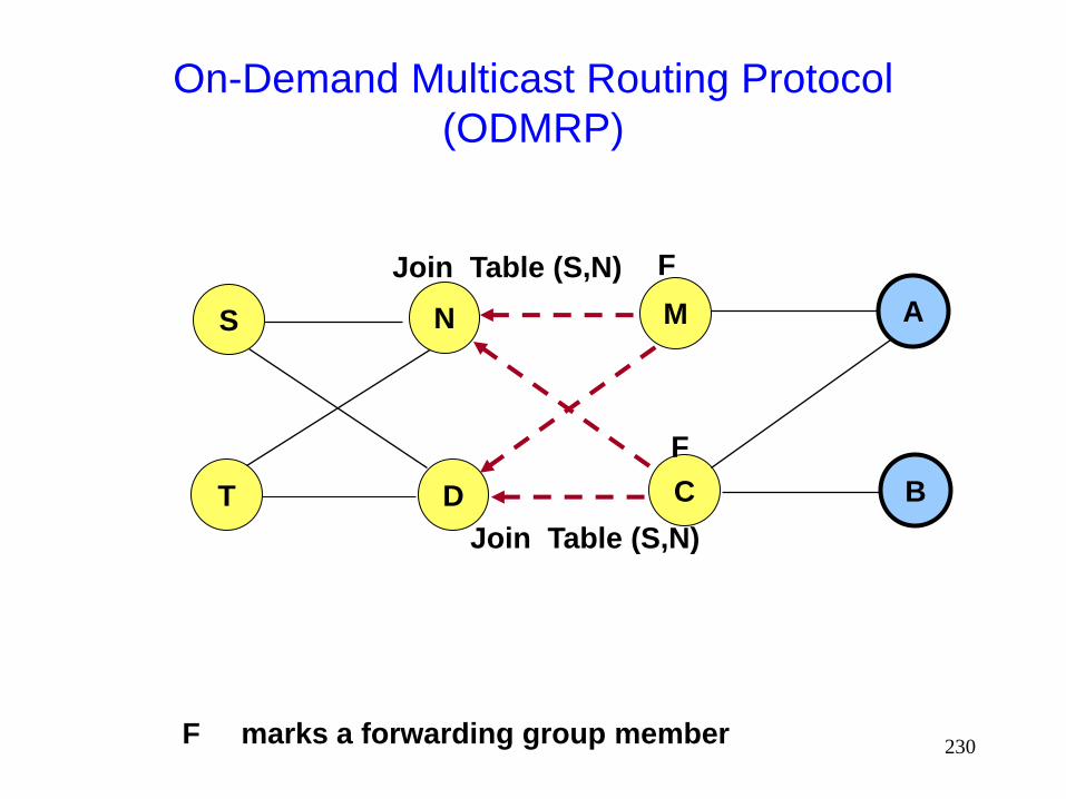
When node N receives the above broadcast, N
becomes member of the forwarding group
When node N becomes a forwarding group member,
it transmits Join Table containing the entry (S,M)
where M is the next hop towards node S
227
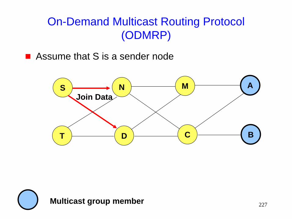
On-Demand Multicast Routing Protocol
(ODMRP)
Assume that S is a sender node
S
T
N
D
Join Data
Multicast group member
M
C
A
B
228
On-Demand Multicast Routing Protocol
(ODMRP)
S
T
N
D
Join Data
Multicast group member
M
C
A
B
Join Data
Join Data
229
On-Demand Multicast Routing Protocol
(ODMRP)
S
T
N
D
Multicast group member
M
C
A
B
Join Table (S,M)
Join Table (S,C)
230
On-Demand Multicast Routing Protocol
(ODMRP)
S
T
N
D
F marks a forwarding group member
M
C
A
B
Join Table (S,N)
Join Table (S,N)
F
F
231
On-Demand Multicast Routing Protocol
(ODMRP)
S
T
N
D
Multicast group member
M
C
A
B
Join Table (S,S) F
F
F

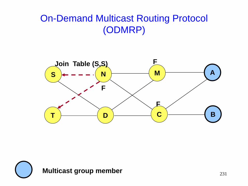
232
On-Demand Multicast Routing Protocol
(ODMRP)
S
T
N
D
Multicast group member
M
C
A
B
F
F
F
Join Data (T)
233
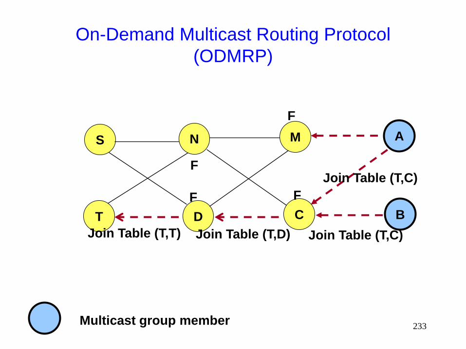
On-Demand Multicast Routing Protocol
(ODMRP)
S
T
N
D
Multicast group member
M
C
A
B
F
F
F
Join Table (T,C)
Join Table (T,C)
Join Table (T,D)
F
Join Table (T,T)

234
ODMRP Multicast Delivery
A sender broadcasts data packets to all its neighbors
Members of the forwarding group forward the packets
Using ODMRP, multiple routes from a sender to a
multicast receiver may exist due to the mesh
structure created by the forwarding group members
235
ODMRP
No explicit join or leave procedure
A sender wishing to stop multicasting data simply stops sending Join Data messages
A multicast group member wishing to leave the group stops sending Join Table messages
A forwarding node ceases its forwarding status unless refreshed by receipt of a Join Table message
Link failure/repair taken into account when updating routes in response to periodic Join Data floods from the senders
236
Other Multicasting Protocols
Several other multicasting proposals have been
made
For a comparison study, see [Lee00Infocom]
237
Geocasting
in
Mobile Ad Hoc Networks
238
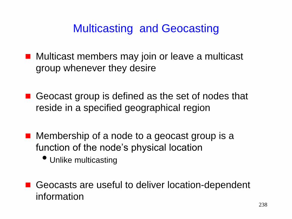
Multicasting and Geocasting
Multicast members may join or leave a multicast
group whenever they desire
Geocast group is defined as the set of nodes that
reside in a specified geographical region
Membership of a node to a geocast group is a
function of the node’s physical location
Unlike multicasting
Geocasts are useful to deliver location-dependent
information

239
Geocasting [Navas97Mobicom]
Navas et al. proposed the notion of geocasting in the
traditional internet
Need new protocols for geocasting in mobile ad hoc
networks
Geocast region: Region to which a geocast message
is to be delivered
240
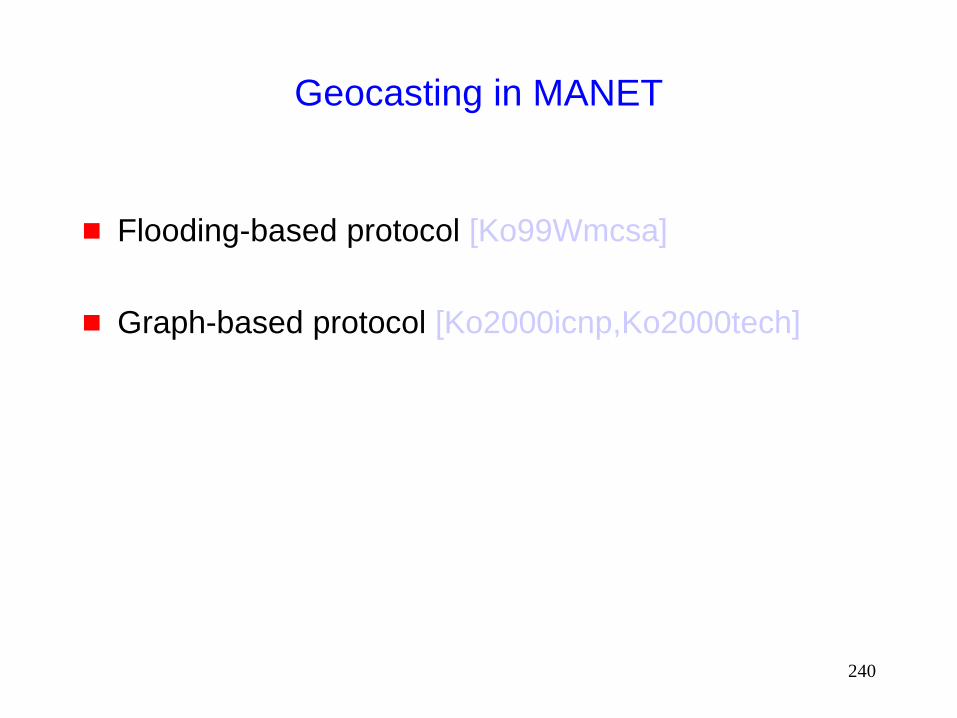
Geocasting in MANET
Flooding-based protocol [Ko99Wmcsa]
Graph-based protocol [Ko2000icnp,Ko2000tech]
241
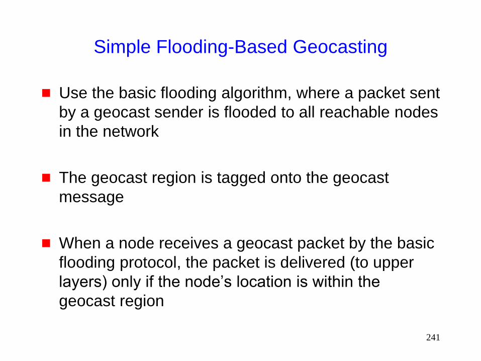
Simple Flooding-Based Geocasting
Use the basic flooding algorithm, where a packet sent
by a geocast sender is flooded to all reachable nodes
in the network
The geocast region is tagged onto the geocast
message
When a node receives a geocast packet by the basic
flooding protocol, the packet is delivered (to upper
layers) only if the node’s location is within the
geocast region

242
Simple Flooding-Based Geocasting
Advantages:
Simplicity
Disadvantages
High overhead
Packet reaches all nodes reachable from the source
243
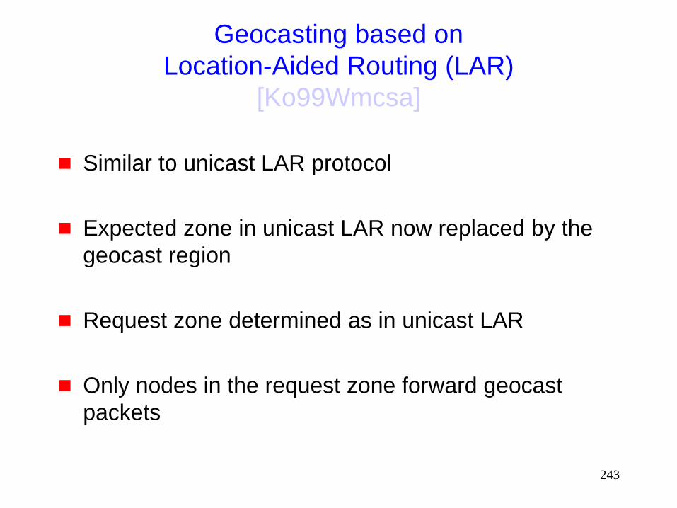
Geocasting based on
Location-Aided Routing (LAR)
[Ko99Wmcsa]
Similar to unicast LAR protocol
Expected zone in unicast LAR now replaced by the
geocast region
Request zone determined as in unicast LAR
Only nodes in the request zone forward geocast
packets
244
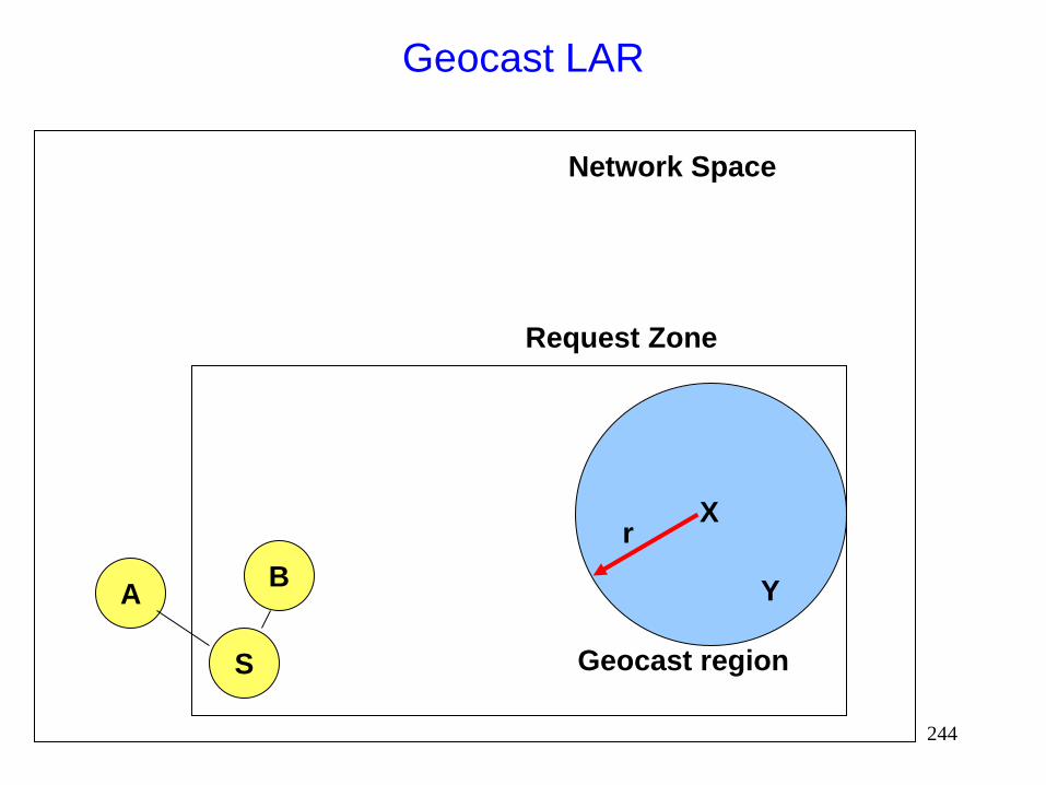
Geocast LAR
X
Y
r
S
Request Zone
Network Space
B A
Geocast region
245
Geocast LAR
If all routes between a geocast member and the
source may contain nodes that are outside the
request zone, geocast will not be delivered to that
member
Trade-off between accuracy and overhead
Larger request zone increases accuracy but may also
increase overhead
Advantage of LAR for geocasting: No need to keep
track of network topology
Good approach when geocasting is performed infrequently
246
GeoTORA [Ko2000icnp,Ko2000tech]
Based on link reversal algorithm TORA for unicasting
in MANET
TORA maintains a Directed Acyclic Graph (DAG)
with only the destination node being a sink
247
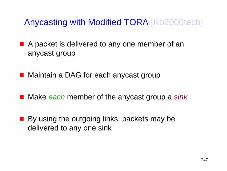
Anycasting with Modified TORA [Ko2000tech]
A packet is delivered to any one member of an
anycast group
Maintain a DAG for each anycast group
Make each member of the anycast group a sink
By using the outgoing links, packets may be
delivered to any one sink
248
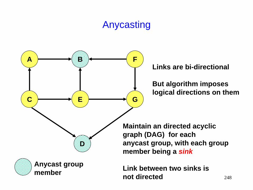
Anycasting
A F B
C E G
D
Maintain an directed acyclic
graph (DAG) for each
anycast group, with each group
member being a sink
Link between two sinks is
not directed
Links are bi-directional
But algorithm imposes
logical directions on them
Anycast group
member

249
DAG for Anycasting
Since links between anycast group members are not
given a direction, the graph is not exactly a “directed”
acyclic graph
So use of the term DAG here is imprecise
Ignoring links between anycast group members, rest
of the graph is a DAG
250
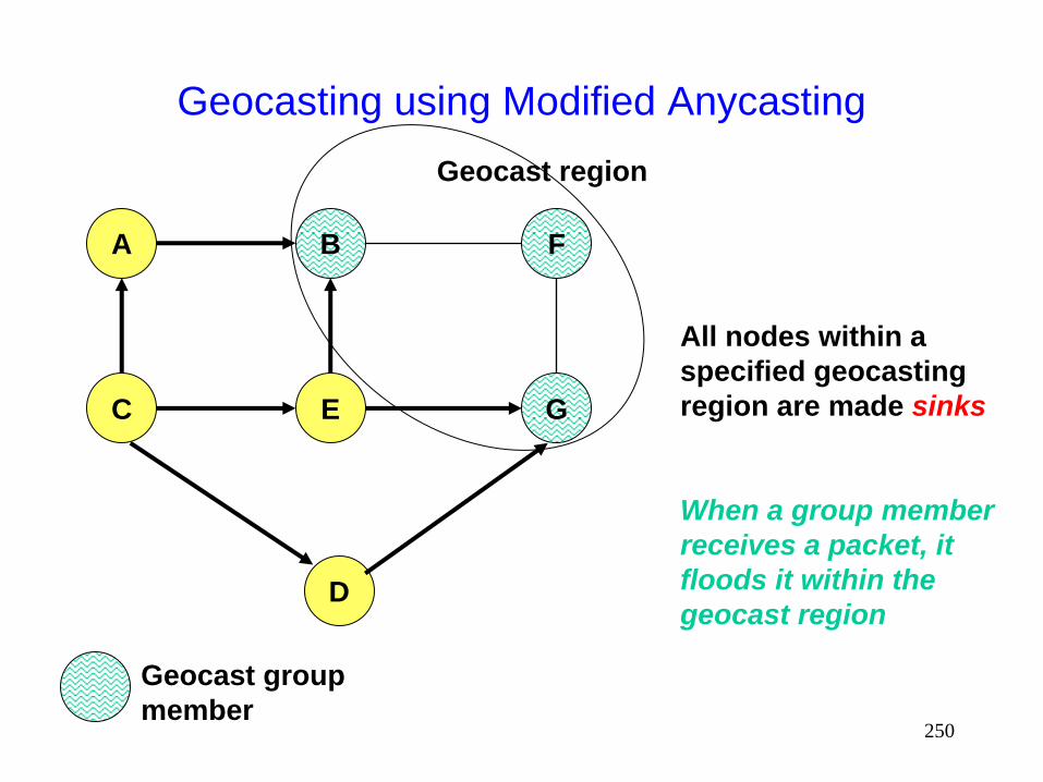
Geocasting using Modified Anycasting
A F B
C E G
D
All nodes within a
specified geocasting
region are made sinks
When a group member
receives a packet, it
floods it within the
geocast region
Geocast group
member
Geocast region
251
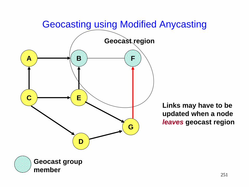
Geocasting using Modified Anycasting
A F B
C E
G
D
Links may have to be
updated when a node
leaves geocast region
Geocast group
member
Geocast region

252
Geocasting using Modified Anycasting
A F B
C
E
G
D
Links may have to be
updated when a node
enters geocast region
Geocast group
member
Geocast region

253
Other Geocasting Schemes
[Macwan01thesis] divides space into a grid, and
maintains a graph structure for each grid square.
Data transmitted using grid structures for the grid squares
that intersect with the geocast region.
d
a b
e f
c

254
Other Geocasting Schemes
Mesh-based geocast routing [Boleng01]
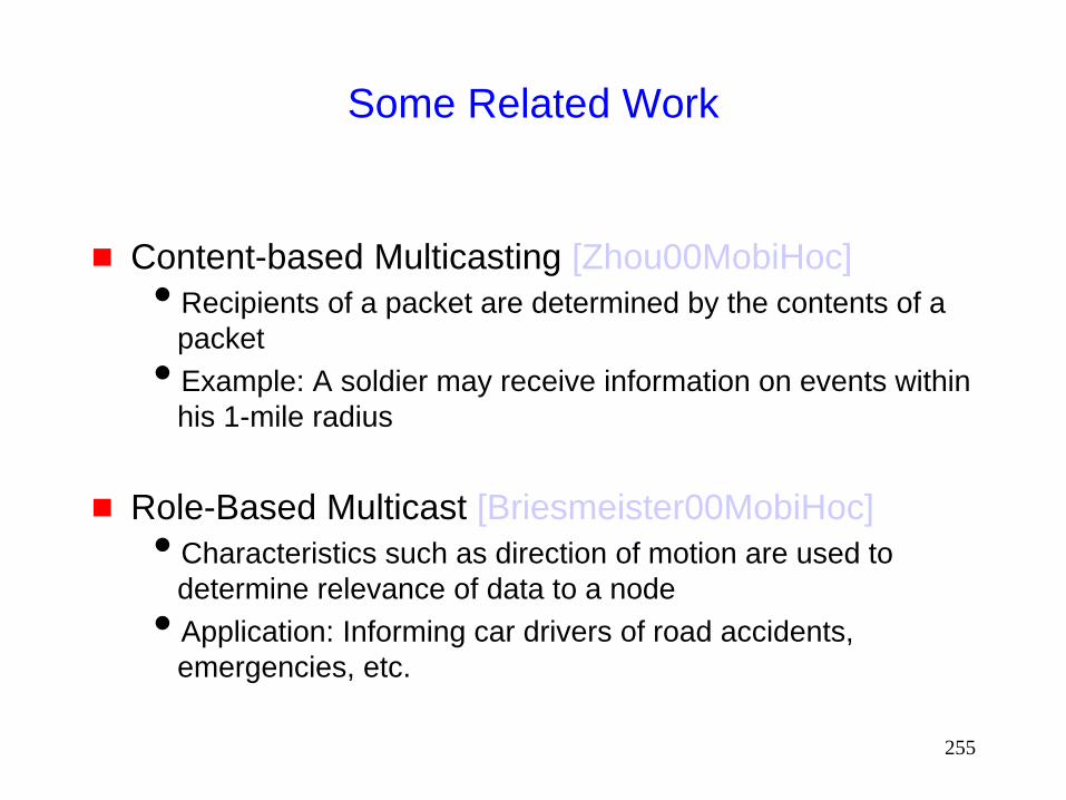
255
Some Related Work
Content-based Multicasting [Zhou00MobiHoc]
Recipients of a packet are determined by the contents of a
packet
Example: A soldier may receive information on events within
his 1-mile radius
Role-Based Multicast [Briesmeister00MobiHoc]
Characteristics such as direction of motion are used to
determine relevance of data to a node
Application: Informing car drivers of road accidents,
emergencies, etc.
256
Capacity of Ad Hoc Networks

257
Capacity of Fixed Ad Hoc Networks
[Gupta00it]
n nodes in area A transmitting at W bits/sec using a fixed range (distance between a random pair of nodes is O(sqrt(n))
Bit-distance product that can be transported by the network per second is
Q ( W sqrt (A n) )
Throughput per node
Q ( W / sqrt (n) )

258
Capacity of Mobile Ad Hoc Networks
[Grossglauser01Infocom]
Assume random motion
Any two nodes become neighbors once in a while
Each node assumed sender for one session, and destination for another session
Relay packets through at most one other node Packet go from S to D directly, when S and D are neighbors,
or from S to a relay and the the relay to D, when each pair becomes neighbor respectively
Throughput of each session is O(1) Independent of n
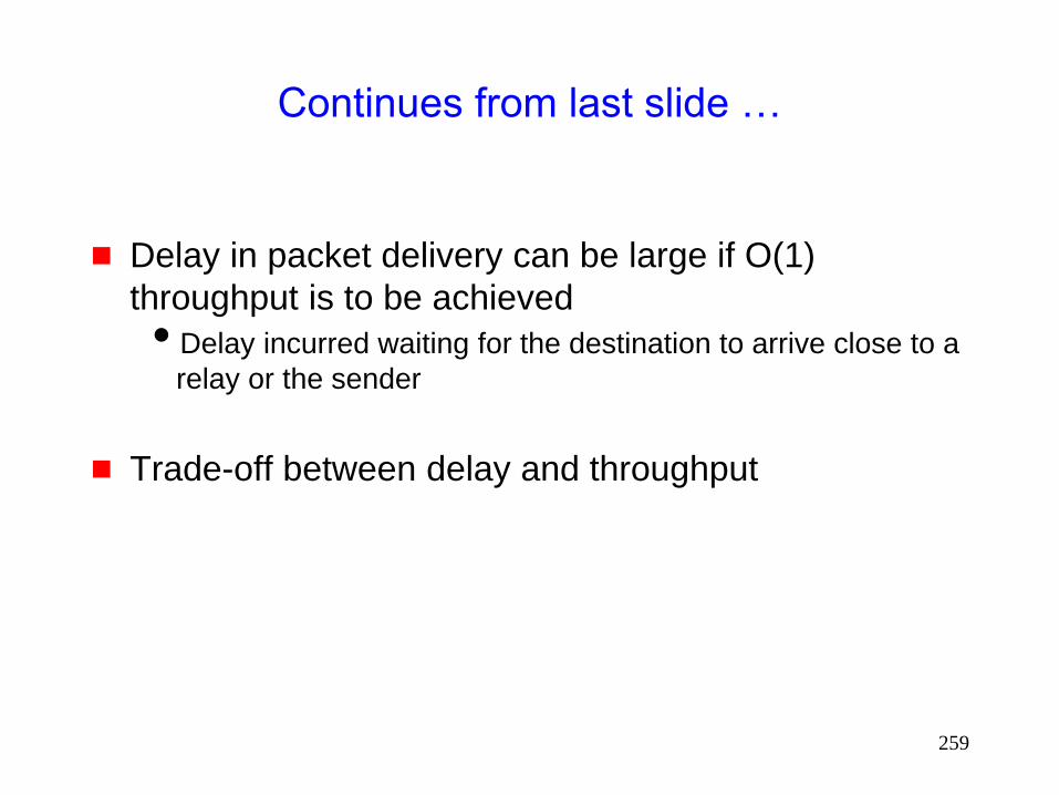
259
Continues from last slide …
Delay in packet delivery can be large if O(1)
throughput is to be achieved
Delay incurred waiting for the destination to arrive close to a
relay or the sender
Trade-off between delay and throughput
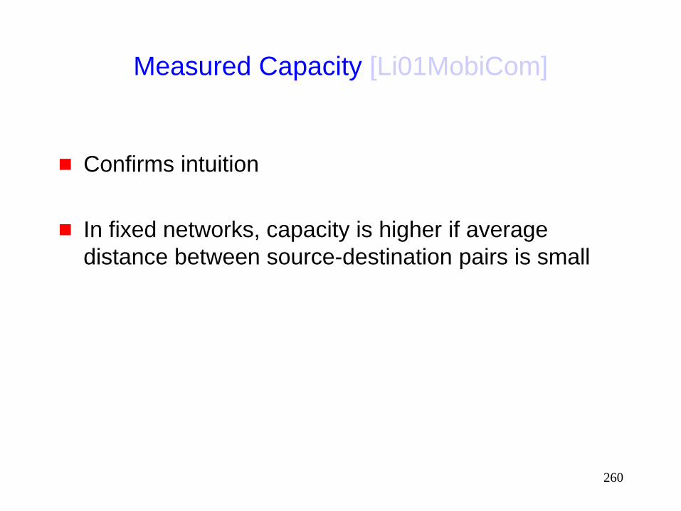
260
Measured Capacity [Li01MobiCom]
Confirms intuition
In fixed networks, capacity is higher if average
distance between source-destination pairs is small
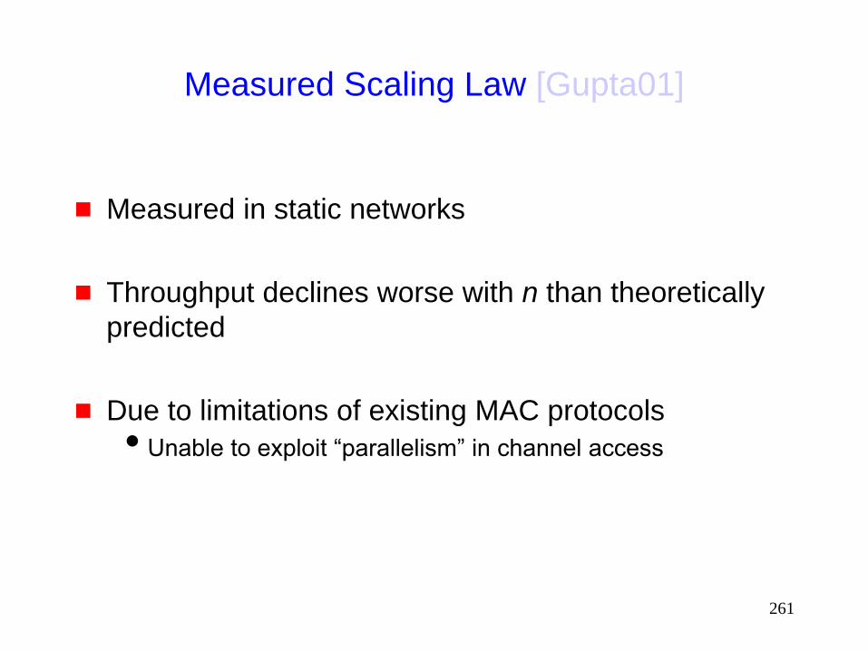
261
Measured Scaling Law [Gupta01]
Measured in static networks
Throughput declines worse with n than theoretically
predicted
Due to limitations of existing MAC protocols
Unable to exploit “parallelism” in channel access

262
Capacity
How to design MAC and routing protocols to
approach theoretical capacity ?
Open problem
263
Medium Access Control Protocols

264
MAC Protocols: Issues
Hidden Terminal Problem
Reliability
Collision avoidance
Congestion control
Fairness
Energy efficiency
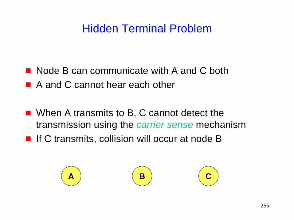
265
A B C
Hidden Terminal Problem
Node B can communicate with A and C both
A and C cannot hear each other
When A transmits to B, C cannot detect the
transmission using the carrier sense mechanism
If C transmits, collision will occur at node B
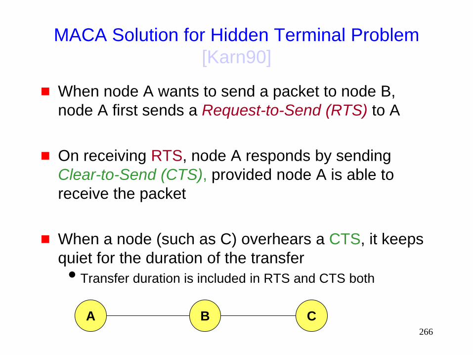
266
MACA Solution for Hidden Terminal Problem
[Karn90]
When node A wants to send a packet to node B,
node A first sends a Request-to-Send (RTS) to A
On receiving RTS, node A responds by sending
Clear-to-Send (CTS), provided node A is able to
receive the packet
When a node (such as C) overhears a CTS, it keeps
quiet for the duration of the transfer
Transfer duration is included in RTS and CTS both
A B C

267
Reliability
Wireless links are prone to errors. High packet loss
rate detrimental to transport-layer performance.
Mechanisms needed to reduce packet loss rate
experienced by upper layers
A B C
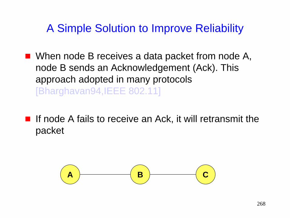
268
A Simple Solution to Improve Reliability
When node B receives a data packet from node A,
node B sends an Acknowledgement (Ack). This
approach adopted in many protocols
[Bharghavan94,IEEE 802.11]
If node A fails to receive an Ack, it will retransmit the
packet
A B C

269
IEEE 802.11 Wireless MAC
Distributed and centralized MAC components
Distributed Coordination Function (DCF)
Point Coordination Function (PCF)
DCF suitable for multi-hop ad hoc networking
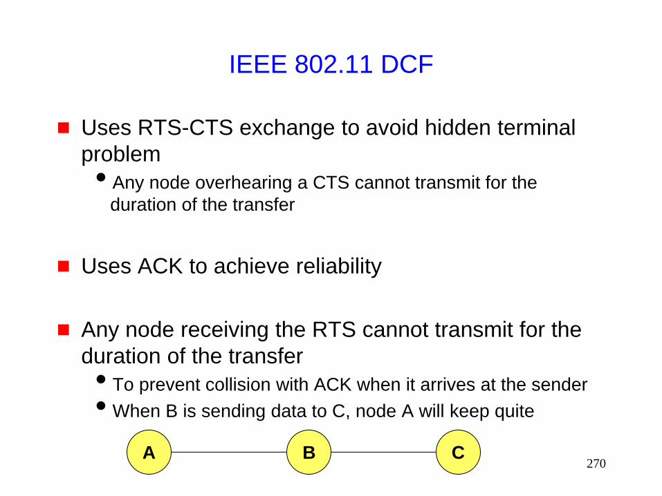
270
IEEE 802.11 DCF
Uses RTS-CTS exchange to avoid hidden terminal
problem
Any node overhearing a CTS cannot transmit for the
duration of the transfer
Uses ACK to achieve reliability
Any node receiving the RTS cannot transmit for the
duration of the transfer
To prevent collision with ACK when it arrives at the sender
When B is sending data to C, node A will keep quite
A B C
271
Collision Avoidance
With half-duplex radios, collision detection is not
possible
CSMA/CA: Wireless MAC protocols often use
collision avoidance techniques, in conjunction with a
(physical or virtual) carrier sense mechanism
Carrier sense: When a node wishes to transmit a
packet, it first waits until the channel is idle
Collision avoidance: Once channel becomes idle, the
node waits for a randomly chosen duration before
attempting to transmit

272
Congestion Avoidance:
IEEE 802.1 DCF
When transmitting a packet, choose a backoff interval
in the range [0,cw]
cw is contention window
Count down the backoff interval when medium is idle
Count-down is suspended if medium becomes busy
When backoff interval reaches 0, transmit RTS
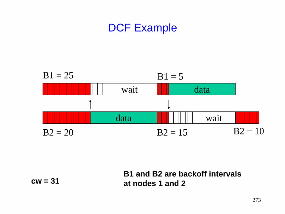
273
DCF Example
data
wait
B1 = 5
B2 = 15
B1 = 25
B2 = 20
data
wait
B1 and B2 are backoff intervals
at nodes 1 and 2 cw = 31
B2 = 10
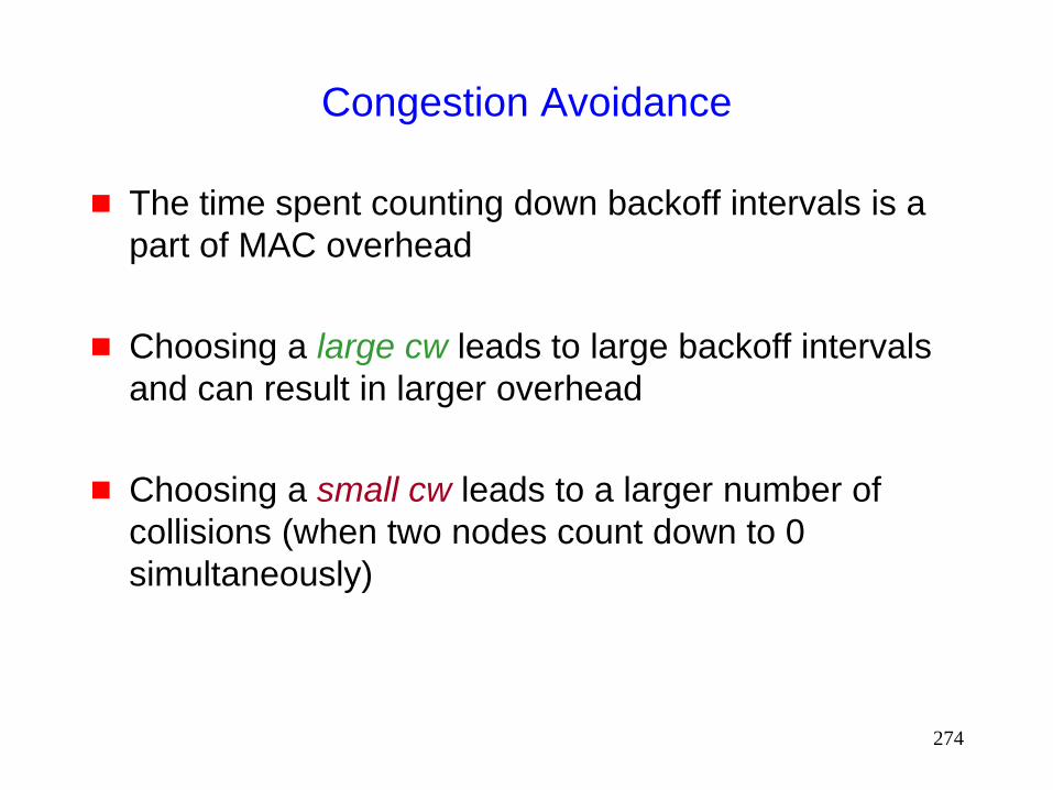
274
Congestion Avoidance
The time spent counting down backoff intervals is a
part of MAC overhead
Choosing a large cw leads to large backoff intervals
and can result in larger overhead
Choosing a small cw leads to a larger number of
collisions (when two nodes count down to 0
simultaneously)

275
MAC Protocols: Issues
Hidden Terminal Problem
Reliability
Collision avoidance
Congestion control
Fairness
Energy efficiency
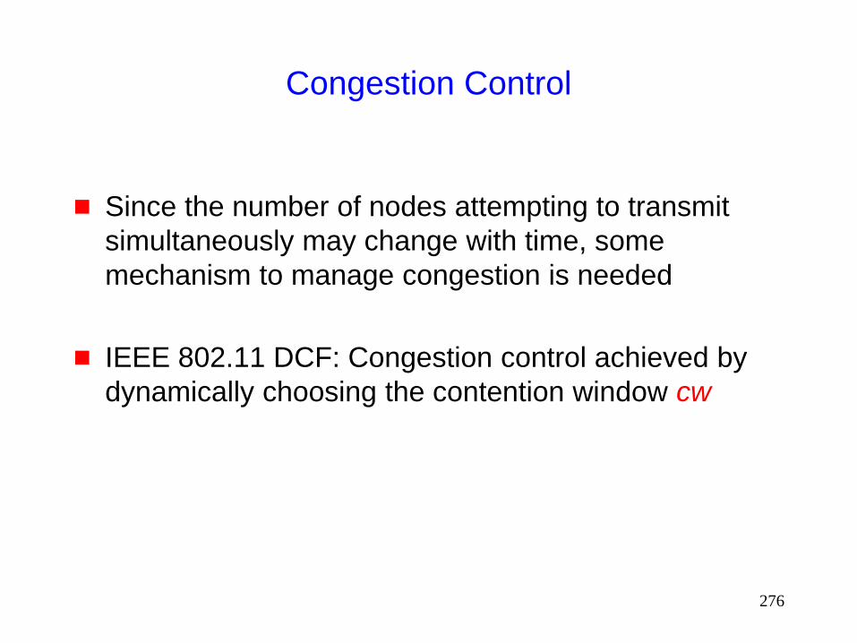
276
Congestion Control
Since the number of nodes attempting to transmit
simultaneously may change with time, some
mechanism to manage congestion is needed
IEEE 802.11 DCF: Congestion control achieved by
dynamically choosing the contention window cw
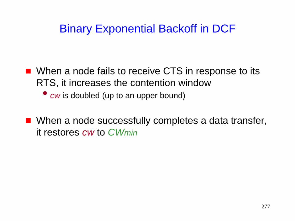
277
Binary Exponential Backoff in DCF
When a node fails to receive CTS in response to its
RTS, it increases the contention window
cw is doubled (up to an upper bound)
When a node successfully completes a data transfer,
it restores cw to CWmin
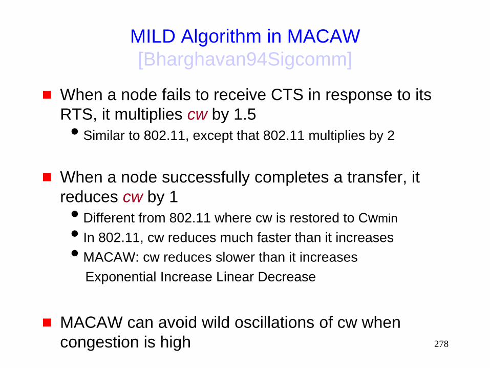
278
MILD Algorithm in MACAW
[Bharghavan94Sigcomm]
When a node fails to receive CTS in response to its
RTS, it multiplies cw by 1.5
Similar to 802.11, except that 802.11 multiplies by 2
When a node successfully completes a transfer, it
reduces cw by 1
Different from 802.11 where cw is restored to Cwmin
In 802.11, cw reduces much faster than it increases
MACAW: cw reduces slower than it increases
Exponential Increase Linear Decrease
MACAW can avoid wild oscillations of cw when
congestion is high

279
IEEE 802.11
Distributed Coordination Function
This slide is deleted (the slide in the MobiCom 2000
handout erroneously duplicated an earlier slide)

280
Fairness Issue
Many definitions of fairness plausible
Simplest definition: All nodes should receive equal
bandwidth
A B
C D
Two flows

281
Fairness Issue
Assume that initially, A and B both choose a backoff
interval in range [0,31] but their RTSs collide
Nodes A and B then choose from range [0,63]
Node A chooses 4 slots and B choose 60 slots
After A transmits a packet, it next chooses from range [0,31]
It is possible that A may transmit several packets before B
transmits its first packet
A B
C D
Two flows
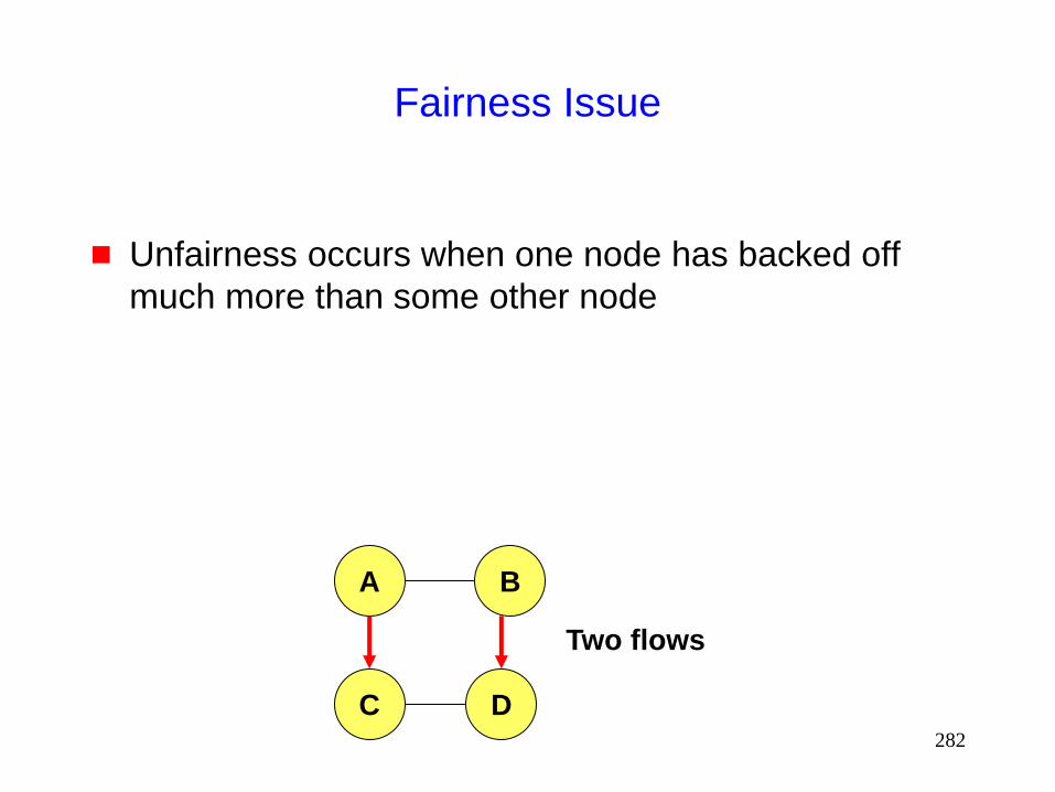
282
Fairness Issue
Unfairness occurs when one node has backed off
much more than some other node
A B
C D
Two flows
283
MACAW Solution for Fairness
When a node transmits a packet, it appends the cw value to the packet, all nodes hearing that cw value use it for their future transmission attempts
Since cw is an indication of the level of congestion in the vicinity of a specific receiver node, MACAW proposes maintaining cw independently for each receiver
Using per-receiver cw is particularly useful in multi-hop environments, since congestion level at different receivers can be very different
284
Weighted Fair Queueing
Assign a weight to each node
Bandwidth used by each node should be proportional
to the weight assigned to the node
285
Distributed Fair Scheduling (DFS)
[Vaidya00Mobicom]
A fully distributed algorithm for achieving weighted
fair queueing
Chooses backoff intervals proportional to
(packet size / weight)
DFS attempts to mimic the centralized Self-Clocked
Fair Queueing algorithm [Golestani]
Works well on a LAN
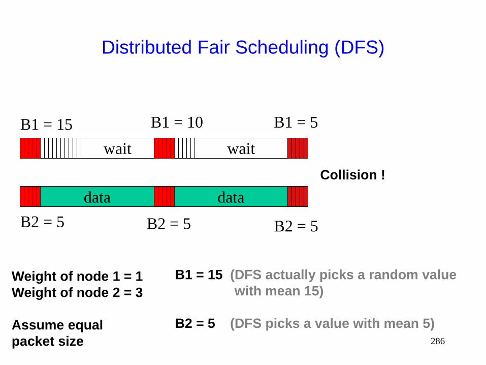
286
Distributed Fair Scheduling (DFS)
data
wait
B1 = 15
B2 = 5
B1 = 15 (DFS actually picks a random value
with mean 15)
B2 = 5 (DFS picks a value with mean 5)
Weight of node 1 = 1
Weight of node 2 = 3
Assume equal
packet size
B1 = 10
B2 = 5
data
wait
B1 = 5
B2 = 5
Collision !

287
Impact of Collisions
After collision resolution, either node 1 or node 2 may
transmit a packet
The two alternatives may have different fairness
properties (since collision resolution can result in
priority inversion)

288
Distributed Fair Scheduling (DFS)
data
wait
B1 = 10
B2 = 5
B1 = 10
B2 = 5
data
wait
B1 = 5
B2 = 5
Collision resolution
data
wait data
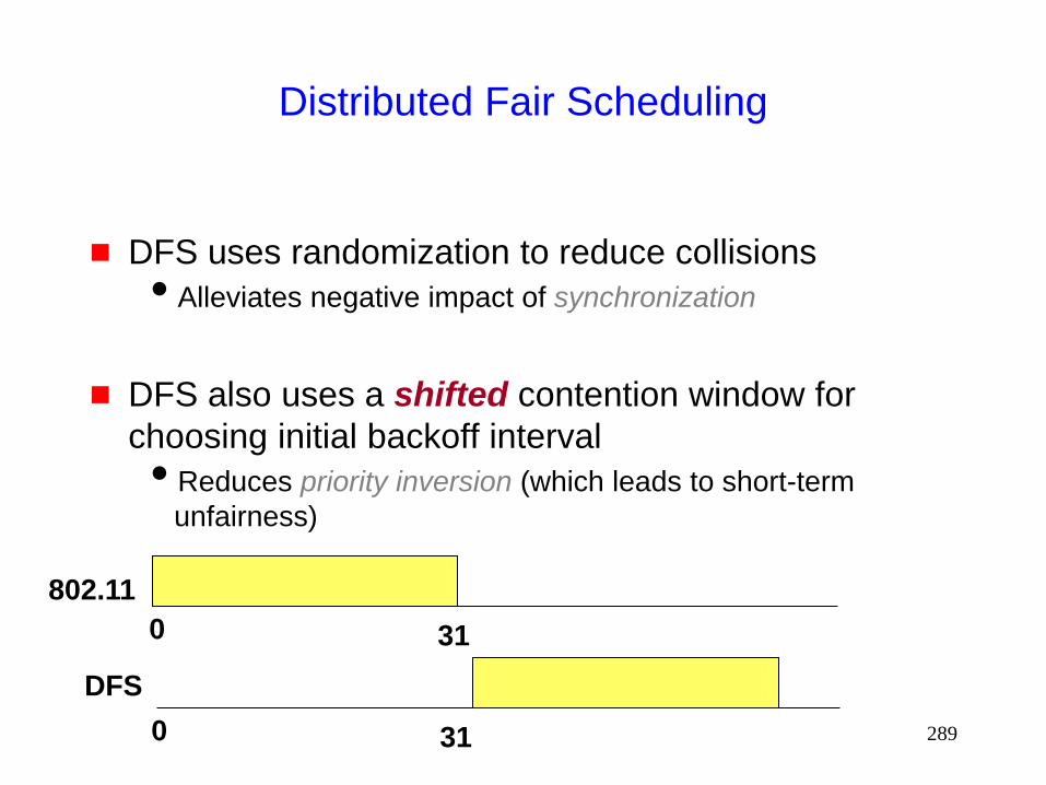
289
Distributed Fair Scheduling
DFS uses randomization to reduce collisions
Alleviates negative impact of synchronization
DFS also uses a shifted contention window for
choosing initial backoff interval
Reduces priority inversion (which leads to short-term
unfairness)
0 31
0 31
802.11
DFS

290
DFS
Due to large cw, DFS can potentially yield lower
throughput than IEEE 802.11
trade-off between fairness and throughput
On multi-hop network, properties of DFS still need to
be characterized
Fairness in multi-hop case affected by hidden
terminals
May need use of a copying technique, analogous to window
copying in MACAW, to share some protocol state
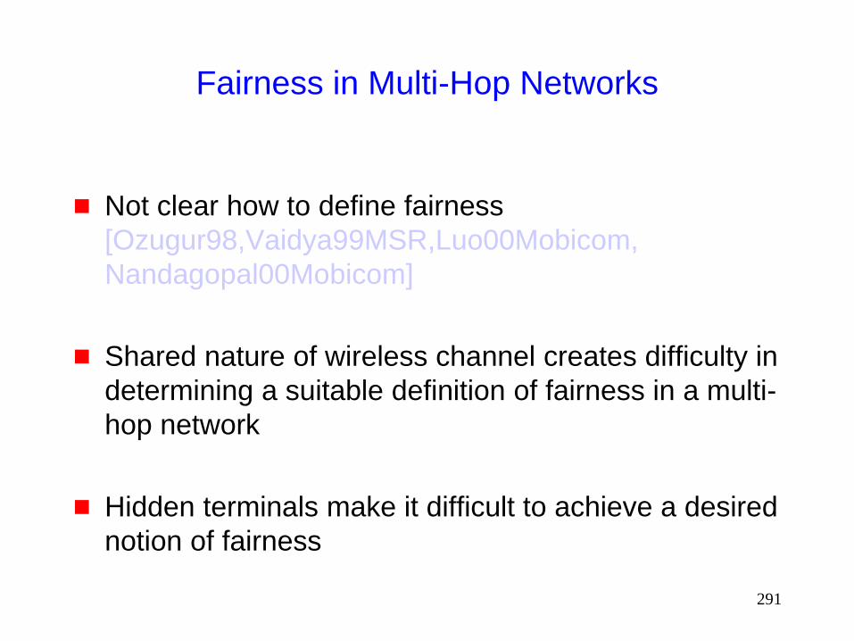
291
Fairness in Multi-Hop Networks
Not clear how to define fairness
[Ozugur98,Vaidya99MSR,Luo00Mobicom,
Nandagopal00Mobicom]
Shared nature of wireless channel creates difficulty in
determining a suitable definition of fairness in a multi-
hop network
Hidden terminals make it difficult to achieve a desired
notion of fairness
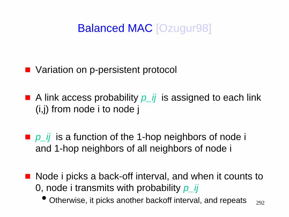
292
Balanced MAC [Ozugur98]
Variation on p-persistent protocol
A link access probability p_ij is assigned to each link
(i,j) from node i to node j
p_ij is a function of the 1-hop neighbors of node i
and 1-hop neighbors of all neighbors of node i
Node i picks a back-off interval, and when it counts to
0, node i transmits with probability p_ij
Otherwise, it picks another backoff interval, and repeats
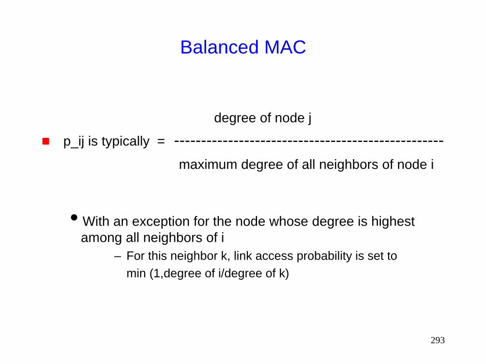
293
Balanced MAC
degree of node j
p_ij is typically = --------------------------------------------------
maximum degree of all neighbors of node i
With an exception for the node whose degree is highest
among all neighbors of i
– For this neighbor k, link access probability is set to
min (1,degree of i/degree of k)
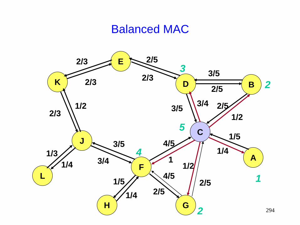
294
Balanced MAC
K
E
D B
J
L F
C
A
H G
2/3
2/3
2/3
2/3
2/5
2/5 2/5
2/5
2/5
3/5
3/5
1/2
1/4
1/4
1/4
1/2
1/5
1/2
4/5
4/5
1
3/4
3/5
1/5
1/3 3/4
1
2
2
4
3
5
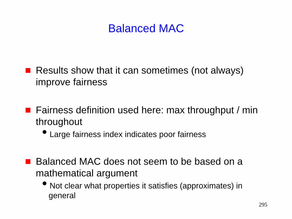
295
Balanced MAC
Results show that it can sometimes (not always)
improve fairness
Fairness definition used here: max throughput / min
throughout
Large fairness index indicates poor fairness
Balanced MAC does not seem to be based on a
mathematical argument
Not clear what properties it satisfies (approximates) in
general
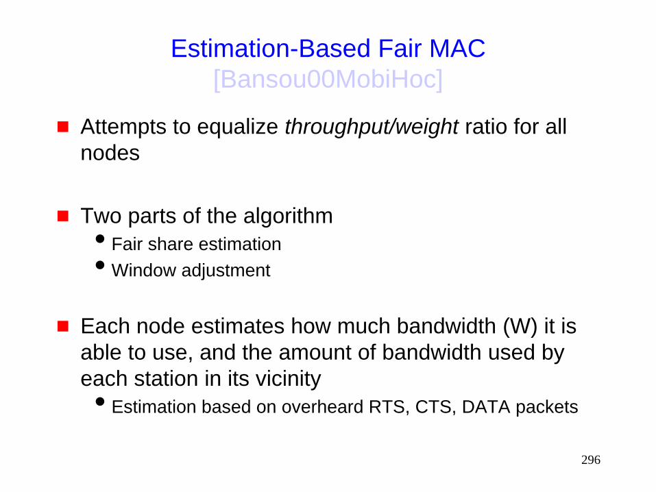
296
Estimation-Based Fair MAC
[Bansou00MobiHoc]
Attempts to equalize throughput/weight ratio for all
nodes
Two parts of the algorithm
Fair share estimation
Window adjustment
Each node estimates how much bandwidth (W) it is
able to use, and the amount of bandwidth used by
each station in its vicinity
Estimation based on overheard RTS, CTS, DATA packets

297
Estimation-Based Fair MAC
Fair share estimation: Node estimates how much
bandwidth (Wi) it is able to use, and the amount of
bandwidth (Wo) used by by all other neighbors
combined
Estimation based on overheard RTS, CTS, DATA packets
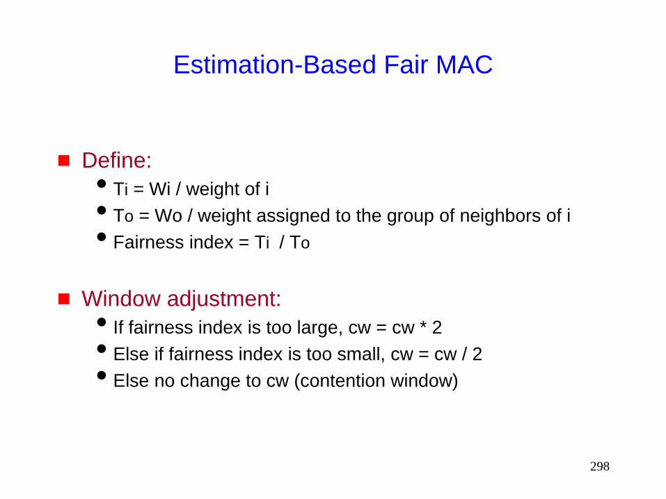
298
Estimation-Based Fair MAC
Define:
Ti = Wi / weight of i
To = Wo / weight assigned to the group of neighbors of i
Fairness index = Ti / To
Window adjustment:
If fairness index is too large, cw = cw * 2
Else if fairness index is too small, cw = cw / 2
Else no change to cw (contention window)
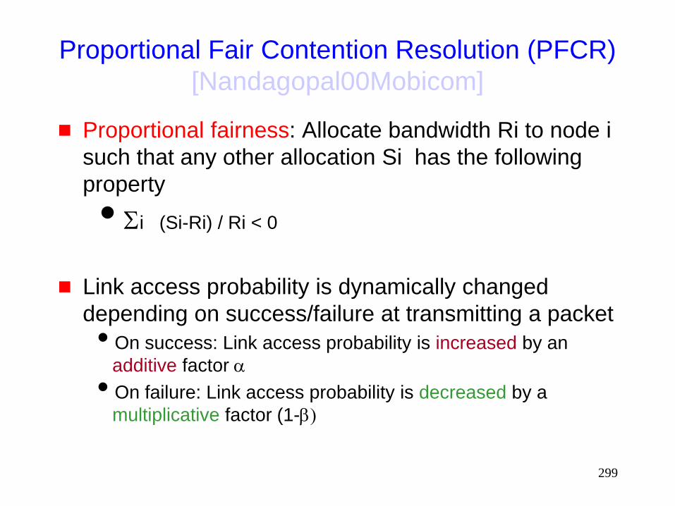
299
Proportional Fair Contention Resolution (PFCR)
[Nandagopal00Mobicom]
Proportional fairness: Allocate bandwidth Ri to node i
such that any other allocation Si has the following
property
Si (Si-Ri) / Ri < 0
Link access probability is dynamically changed
depending on success/failure at transmitting a packet
On success: Link access probability is increased by an
additive factor a
On failure: Link access probability is decreased by a
multiplicative factor (1-b)
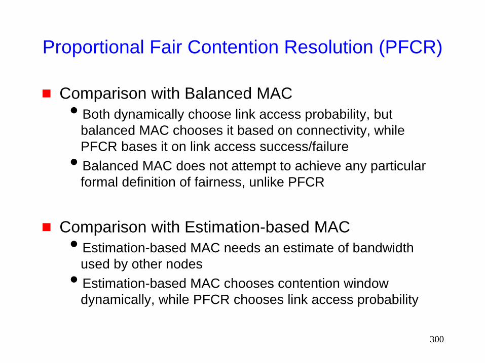
300
Proportional Fair Contention Resolution (PFCR)
Comparison with Balanced MAC
Both dynamically choose link access probability, but
balanced MAC chooses it based on connectivity, while
PFCR bases it on link access success/failure
Balanced MAC does not attempt to achieve any particular
formal definition of fairness, unlike PFCR
Comparison with Estimation-based MAC
Estimation-based MAC needs an estimate of bandwidth
used by other nodes
Estimation-based MAC chooses contention window
dynamically, while PFCR chooses link access probability
301
Sender-Initiated Protocols
The protocols discussed so far are sender-initiated
protocols
The sender initiates a packet transfer to a receiver
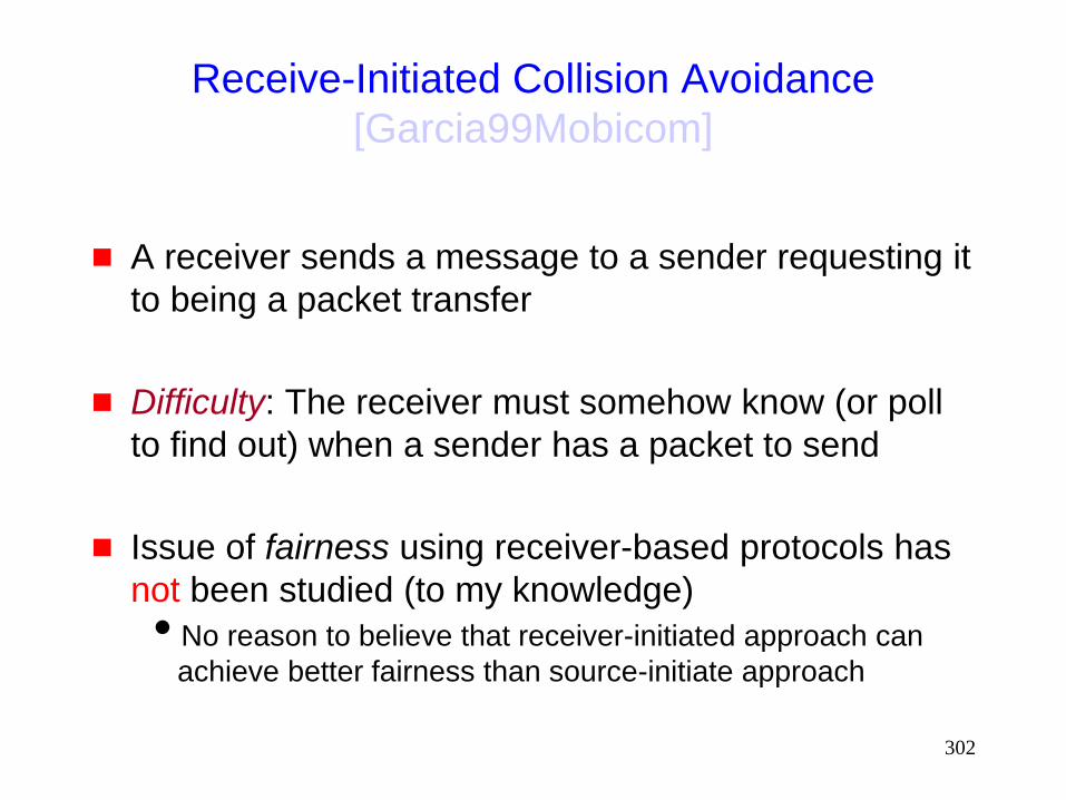
302
Receive-Initiated Collision Avoidance
[Garcia99Mobicom]
A receiver sends a message to a sender requesting it
to being a packet transfer
Difficulty: The receiver must somehow know (or poll
to find out) when a sender has a packet to send
Issue of fairness using receiver-based protocols has
not been studied (to my knowledge)
No reason to believe that receiver-initiated approach can
achieve better fairness than source-initiate approach
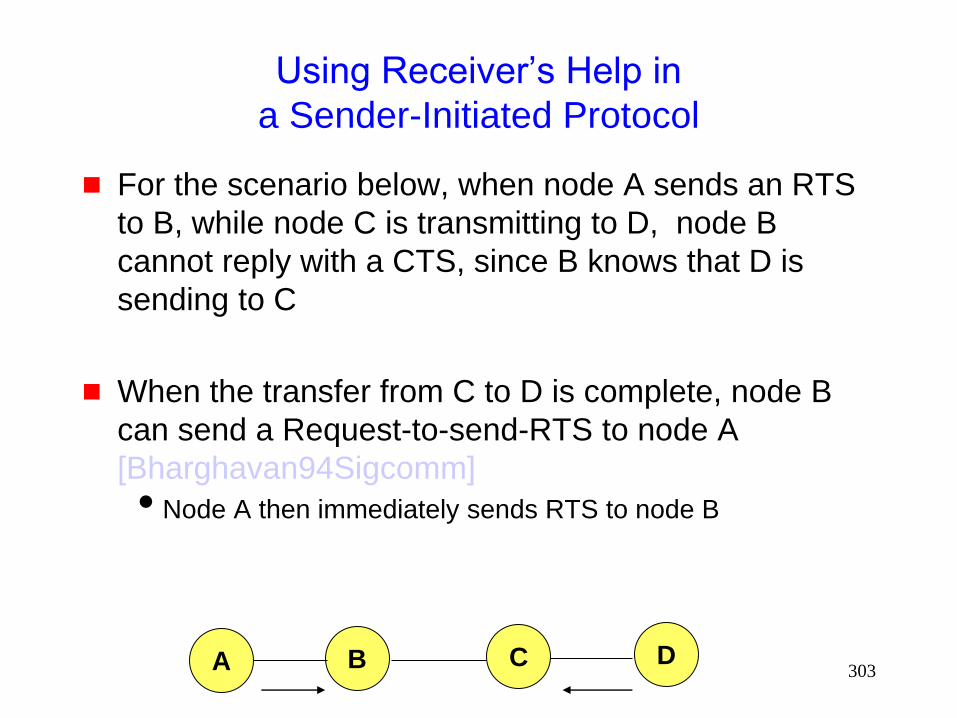
303
Using Receiver’s Help in
a Sender-Initiated Protocol
For the scenario below, when node A sends an RTS
to B, while node C is transmitting to D, node B
cannot reply with a CTS, since B knows that D is
sending to C
When the transfer from C to D is complete, node B
can send a Request-to-send-RTS to node A
[Bharghavan94Sigcomm]
Node A then immediately sends RTS to node B
A B C D
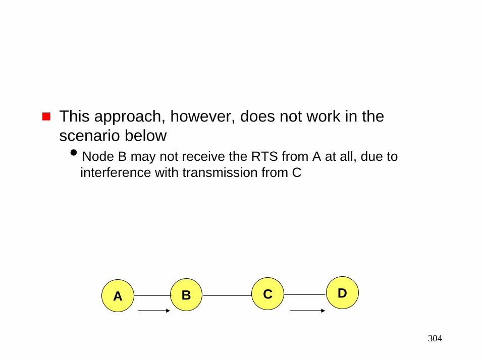
304
This approach, however, does not work in the
scenario below
Node B may not receive the RTS from A at all, due to
interference with transmission from C
A B C D
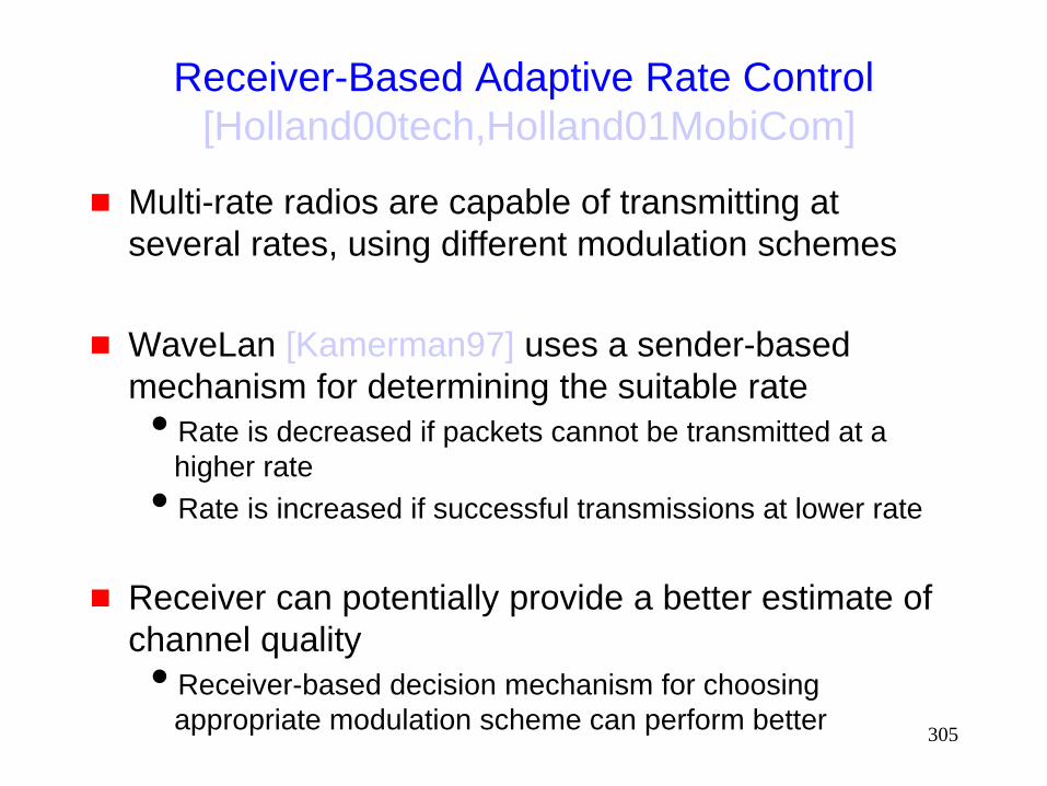
305
Receiver-Based Adaptive Rate Control
[Holland00tech,Holland01MobiCom]
Multi-rate radios are capable of transmitting at
several rates, using different modulation schemes
WaveLan [Kamerman97] uses a sender-based
mechanism for determining the suitable rate
Rate is decreased if packets cannot be transmitted at a
higher rate
Rate is increased if successful transmissions at lower rate
Receiver can potentially provide a better estimate of
channel quality
Receiver-based decision mechanism for choosing
appropriate modulation scheme can perform better
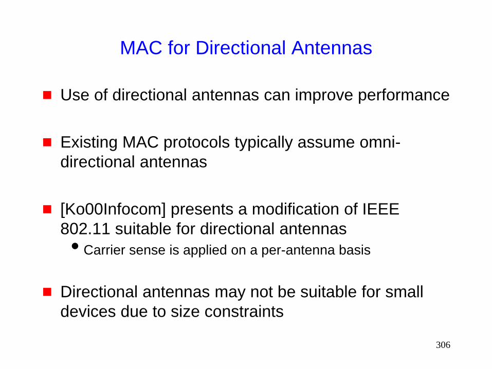
306
MAC for Directional Antennas
Use of directional antennas can improve performance
Existing MAC protocols typically assume omni-
directional antennas
[Ko00Infocom] presents a modification of IEEE
802.11 suitable for directional antennas
Carrier sense is applied on a per-antenna basis
Directional antennas may not be suitable for small
devices due to size constraints
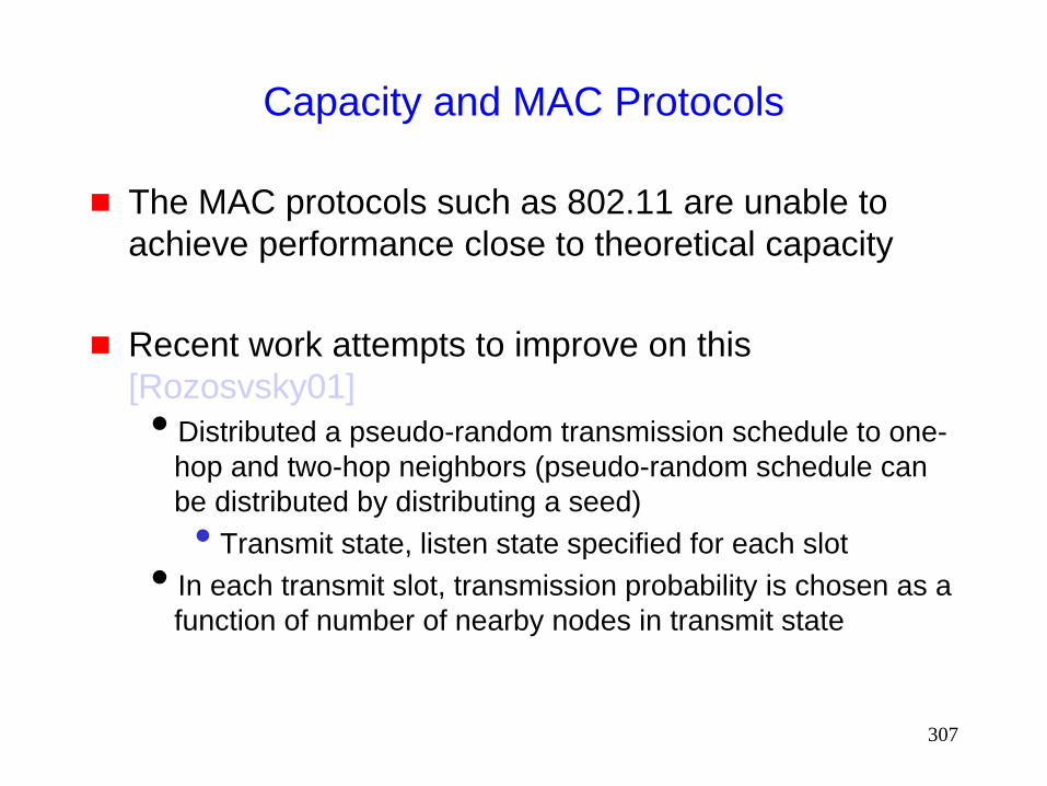
307
Capacity and MAC Protocols
The MAC protocols such as 802.11 are unable to
achieve performance close to theoretical capacity
Recent work attempts to improve on this
[Rozosvsky01]
Distributed a pseudo-random transmission schedule to one-
hop and two-hop neighbors (pseudo-random schedule can
be distributed by distributing a seed)
• Transmit state, listen state specified for each slot
In each transmit slot, transmission probability is chosen as a
function of number of nearby nodes in transmit state

308
MAC Protocols: Issues
Hidden Terminal Problem
Reliability
Collision avoidance
Congestion control
Fairness
Energy efficiency

309
Energy Conserving MAC
Since many mobile hosts are operated by batteries,
MAC protocols which conserve energy are of interest
Proposals for reducing energy consumption typically
suggest turning the radio off when not needed

310
Power Saving Mode in IEEE 802.11
(Infrastructure Mode)
An Access Point periodically transmits a beacon
indicating which nodes have packets waiting for them
Each power saving (PS) node wakes up periodically
to receive the beacon
If a node has a packet waiting, then it sends a PS-
Poll
After waiting for a backoff interval in [0,CWmin]
Access Point sends the data in response to PS-poll

311
Power Aware Multi-Access Protocol (PAMAS)
[Singh98]
A node powers off its radio while a neighbor is
transmitting to someone else
Node A sending to B
Node C stays powered off
C
B
A
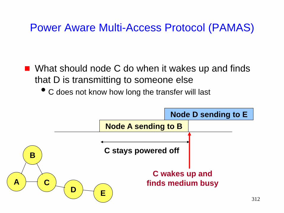
312
Power Aware Multi-Access Protocol (PAMAS)
What should node C do when it wakes up and finds
that D is transmitting to someone else
C does not know how long the transfer will last
Node A sending to B
C stays powered off
C
B
A D E
Node D sending to E
C wakes up and
finds medium busy
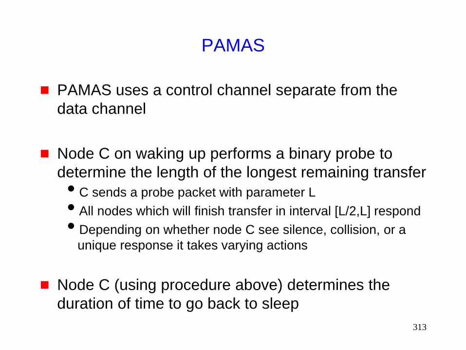
313
PAMAS
PAMAS uses a control channel separate from the
data channel
Node C on waking up performs a binary probe to
determine the length of the longest remaining transfer
C sends a probe packet with parameter L
All nodes which will finish transfer in interval [L/2,L] respond
Depending on whether node C see silence, collision, or a
unique response it takes varying actions
Node C (using procedure above) determines the
duration of time to go back to sleep
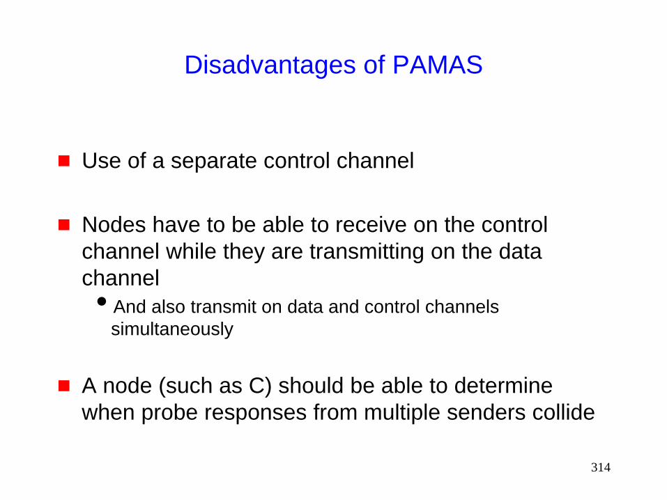
314
Disadvantages of PAMAS
Use of a separate control channel
Nodes have to be able to receive on the control
channel while they are transmitting on the data
channel
And also transmit on data and control channels
simultaneously
A node (such as C) should be able to determine
when probe responses from multiple senders collide
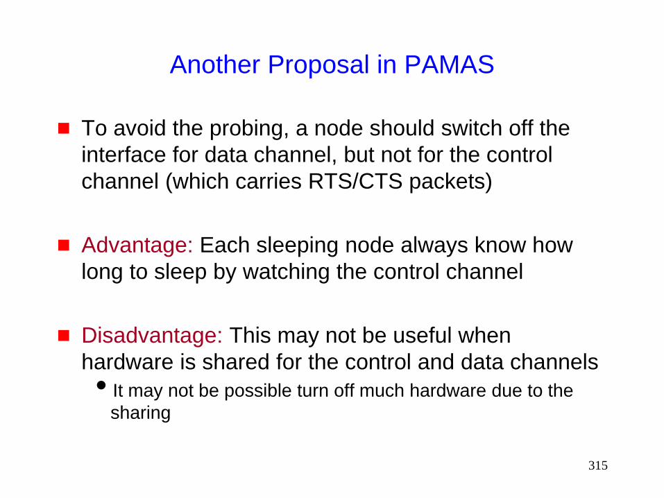
315
Another Proposal in PAMAS
To avoid the probing, a node should switch off the
interface for data channel, but not for the control
channel (which carries RTS/CTS packets)
Advantage: Each sleeping node always know how
long to sleep by watching the control channel
Disadvantage: This may not be useful when
hardware is shared for the control and data channels
It may not be possible turn off much hardware due to the
sharing
316
Other MAC Protocols
Lot of other protocols !
See past MobiCom, WCNC, MilCom, VTC, etc.,
conferences

317
UDP on
Mobile Ad Hoc Networks
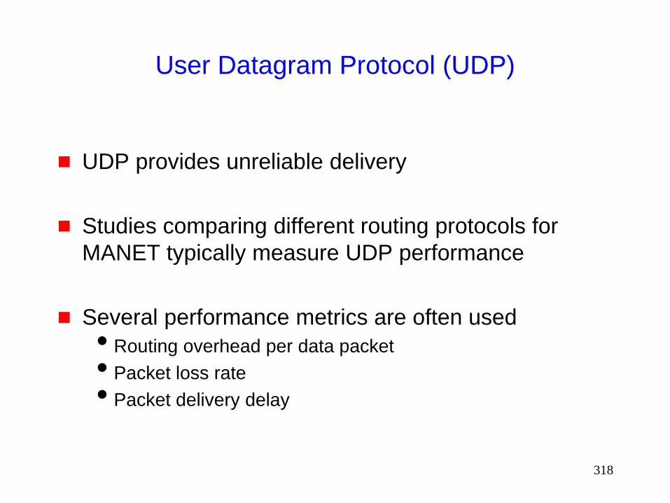
318
User Datagram Protocol (UDP)
UDP provides unreliable delivery
Studies comparing different routing protocols for
MANET typically measure UDP performance
Several performance metrics are often used
Routing overhead per data packet
Packet loss rate
Packet delivery delay

319
UDP Performance
Several relevant studies
[Broch98Mobicom,Das9ic3n,Johansson99Mobicom,
Das00Infocom,Jacquet00Inria]
Results comparing a specific pair of protocols do not
always agree, but some general (and intuitive)
conclusions can be drawn
Reactive protocols may yield lower routing overhead than
proactive protocols when communication density is low
Reactive protocols tend to loose more packets (assuming
than network layer drops packets if a route is not known)
Proactive protocols perform better with high mobility and
dense communication graph

320
UDP Performance
Many variables affect performance
Traffic characteristics
• one-to-many, many-to-one, many-to-many
• small bursts, large file transfers, real-time, non-real-time
Mobility characteristics
• low/high rate of movement
• do nodes tend to move in groups
Node capabilities
• transmission range (fixed, changeable)
• battery constraints
Performance metrics
• delay
• throughput
• latency
• routing overhead
Static or dynamic system characteristics (listed above)

321
UDP Performance
Difficult to identify a single scheme that will perform
well in all environments
Holy grail: Routing protocol that dynamically adapts
to all environments so as to optimize “performance”
Performance metrics may differ in different environments

322
TCP on
Mobile Ad Hoc Networks

323
Overview of
Transmission Control Protocol / Internet Protocol
(TCP/IP)
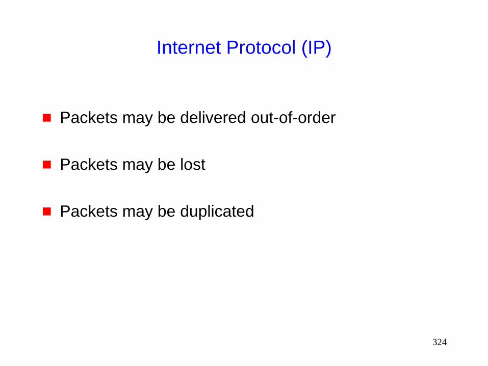
324
Internet Protocol (IP)
Packets may be delivered out-of-order
Packets may be lost
Packets may be duplicated

325
Transmission Control Protocol (TCP)
Reliable ordered delivery
Implements congestion avoidance and control
Reliability achieved by means of retransmissions if necessary
End-to-end semantics Acknowledgements sent to TCP sender confirm delivery of
data received by TCP receiver
Ack for data sent only after data has reached receiver
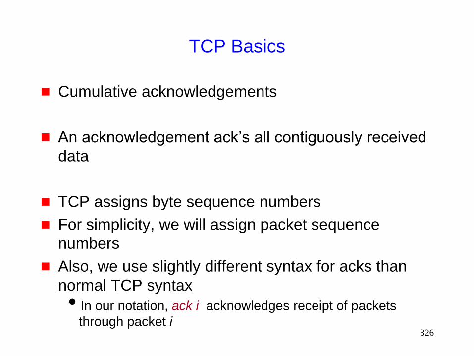
326
TCP Basics
Cumulative acknowledgements
An acknowledgement ack’s all contiguously received
data
TCP assigns byte sequence numbers
For simplicity, we will assign packet sequence
numbers
Also, we use slightly different syntax for acks than
normal TCP syntax
In our notation, ack i acknowledges receipt of packets
through packet i

327
40 39 37 38
35 33
Cumulative Acknowledgements
A new cumulative acknowledgement is generated
only on receipt of a new in-sequence packet
41 40 38 39
35 37
36 34
36 34
i data ack i

328
Duplicate Acknowledgements
A dupack is generated whenever an
out-of-order segment arrives at the receiver
40 39 37 38
36 34
42 41 39 40
36 36
Dupack
(Above example assumes delayed acks) On receipt of 38
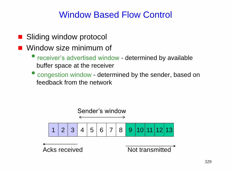
329
Window Based Flow Control
Sliding window protocol
Window size minimum of
receiver’s advertised window - determined by available
buffer space at the receiver
congestion window - determined by the sender, based on
feedback from the network
2 3 4 5 6 7 8 9 10 11 13 1 12
Sender’s window
Acks received Not transmitted
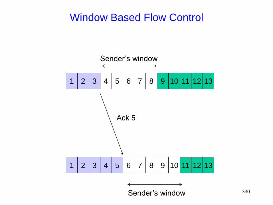
330
Window Based Flow Control
2 3 4 5 6 7 8 9 10 11 13 1 12
Sender’s window
2 3 4 5 6 7 8 9 10 11 13 1 12
Sender’s window
Ack 5
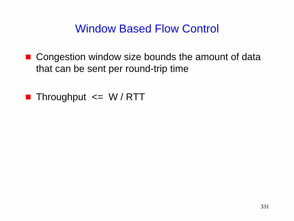
331
Window Based Flow Control
Congestion window size bounds the amount of data
that can be sent per round-trip time
Throughput <= W / RTT

332
Ideal Window Size
Ideal size = delay * bandwidth delay-bandwidth product
What if window size < delay*bw ? Inefficiency (wasted bandwidth)
What if > delay*bw ? Queuing at intermediate routers
• increased RTT due to queuing delays
Potentially, packet loss
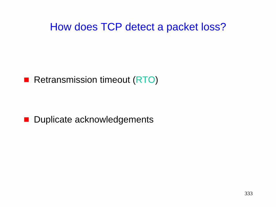
333
How does TCP detect a packet loss?
Retransmission timeout (RTO)
Duplicate acknowledgements

334
Detecting Packet Loss Using
Retransmission Timeout (RTO)
At any time, TCP sender sets retransmission timer for
only one packet
If acknowledgement for the timed packet is not
received before timer goes off, the packet is assumed
to be lost
RTO dynamically calculated

335
Retransmission Timeout (RTO) calculation
RTO = mean + 4 mean deviation
Standard deviation s : s = average of (sample – mean)
Mean deviation d = average of |sample – mean|
Mean deviation easier to calculate than standard deviation
Mean deviation is more conservative: d >= s
2 2
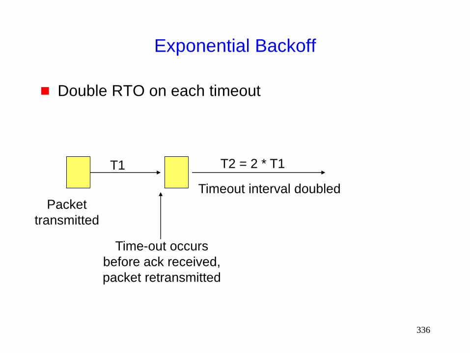
336
Exponential Backoff
Double RTO on each timeout
Packet
transmitted
Time-out occurs
before ack received,
packet retransmitted
Timeout interval doubled
T1 T2 = 2 * T1

337
Fast Retransmission
Timeouts can take too long
how to initiate retransmission sooner?
Fast retransmit

338
Detecting Packet Loss Using Dupacks:
Fast Retransmit Mechanism
Dupacks may be generated due to
packet loss, or
out-of-order packet delivery
TCP sender assumes that a packet loss has occurred
if it receives three dupacks consecutively
12 11 7 8 9 10
Receipt of packets 9, 10 and 11 will each generate
a dupack from the receiver. The sender, on getting
these dupacks, will retransmit packet 8.

339
Congestion Avoidance and Control
Slow Start: cwnd grows exponentially with time
during slow start
When cwnd reaches slow-start threshold, congestion
avoidance is performed
Congestion avoidance: cwnd increases linearly
with time during congestion avoidance
Rate of increase could be lower if sender does not always
have data to send

340
0
2
4
6
8
10
12
14
0 1 2 3 4 5 6 7 8
Time (round trips)
Co
ng
esti
on
Win
do
w s
ize
(seg
men
ts)
Slow start
Congestion
avoidance
Slow start
threshold
Example assumes that acks are not delayed

341
Congestion Control
On detecting a packet loss, TCP sender assumes
that network congestion has occurred
On detecting packet loss, TCP sender drastically
reduces the congestion window
Reducing congestion window reduces amount of data
that can be sent per RTT
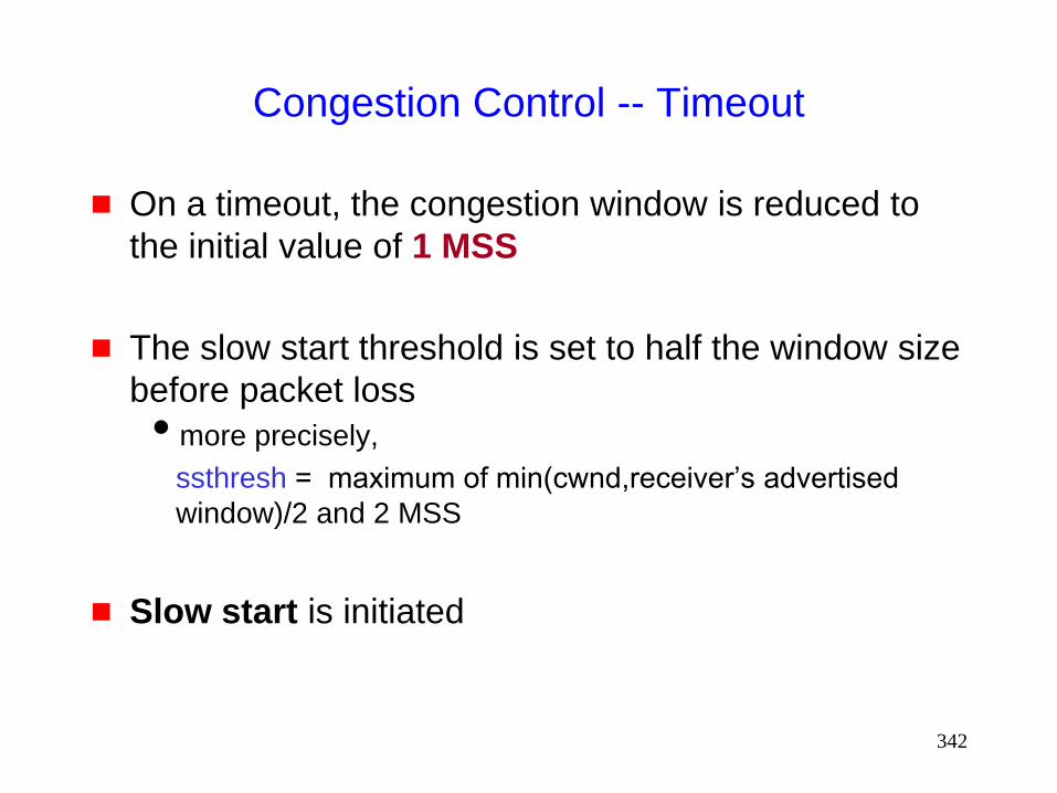
342
Congestion Control -- Timeout
On a timeout, the congestion window is reduced to
the initial value of 1 MSS
The slow start threshold is set to half the window size
before packet loss
more precisely,
ssthresh = maximum of min(cwnd,receiver’s advertised
window)/2 and 2 MSS
Slow start is initiated
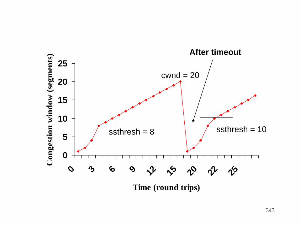
343
0
5
10
15
20
25
0 3 6 9 12 15 20 22 25
Time (round trips)
Co
ng
esti
on
win
do
w (
seg
men
ts)
ssthresh = 8 ssthresh = 10
cwnd = 20
After timeout

344
Congestion Control - Fast retransmit
Fast retransmit occurs when multiple (>= 3) dupacks
come back
Fast recovery follows fast retransmit
Different from timeout : slow start follows timeout
timeout occurs when no more packets are getting across
fast retransmit occurs when a packet is lost, but latter
packets get through
ack clock is still there when fast retransmit occurs
no need to slow start
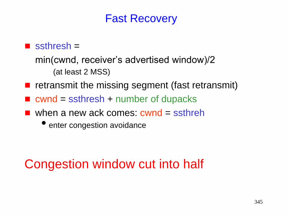
345
Fast Recovery
ssthresh =
min(cwnd, receiver’s advertised window)/2
(at least 2 MSS)
retransmit the missing segment (fast retransmit)
cwnd = ssthresh + number of dupacks
when a new ack comes: cwnd = ssthreh
enter congestion avoidance
Congestion window cut into half
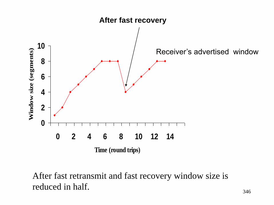
346
0
2
4
6
8
10
0 2 4 6 8 10 12 14
Time (round trips)
Win
do
w s
ize (
seg
men
ts)
After fast retransmit and fast recovery window size is
reduced in half.
Receiver’s advertised window
After fast recovery

347
TCP Reno
Slow-start
Congestion avoidance
Fast retransmit
Fast recovery

348
TCP Performance
in
Mobile Ad Hoc Networks
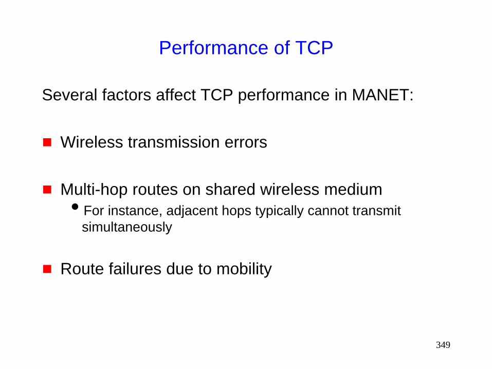
349
Performance of TCP
Several factors affect TCP performance in MANET:
Wireless transmission errors
Multi-hop routes on shared wireless medium
For instance, adjacent hops typically cannot transmit
simultaneously
Route failures due to mobility

350
Random Errors
If number of errors is small, they may be corrected by
an error correcting code
Excessive bit errors result in a packet being
discarded, possibly before it reaches the transport
layer
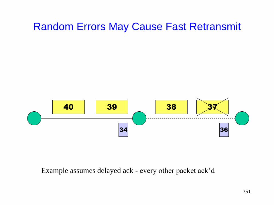
351
Random Errors May Cause Fast Retransmit
40 39 37 38
36 34
Example assumes delayed ack - every other packet ack’d
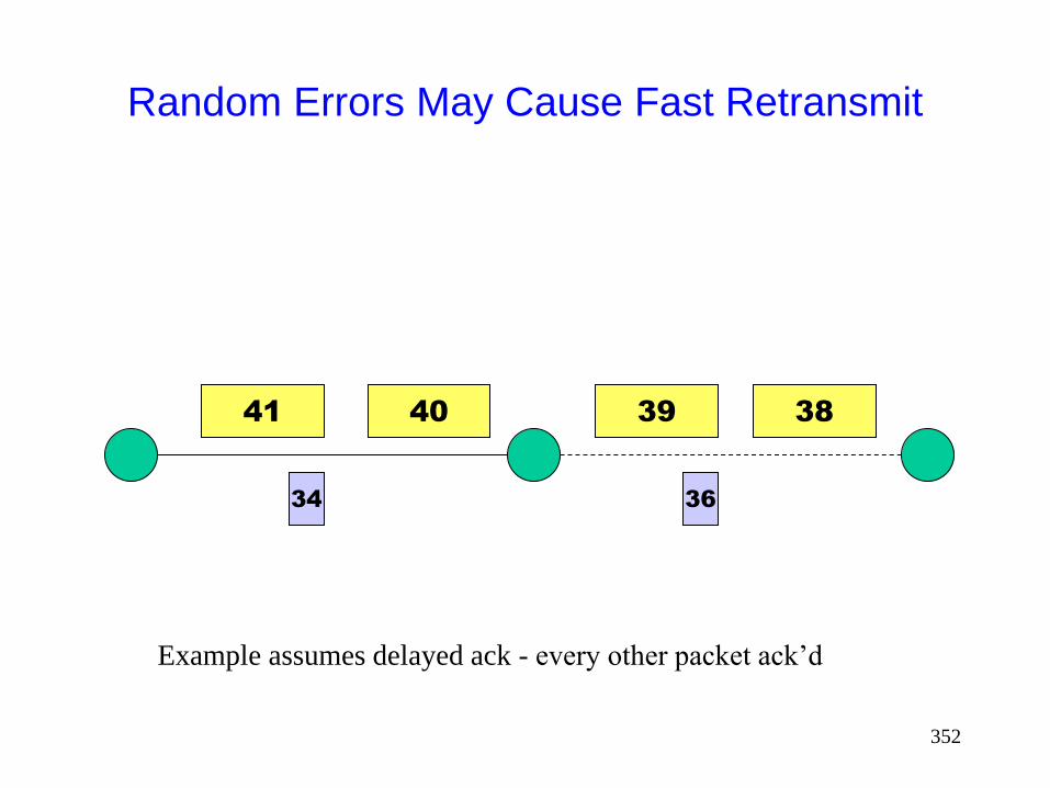
352
Random Errors May Cause Fast Retransmit
41 40 38 39
36 34
Example assumes delayed ack - every other packet ack’d
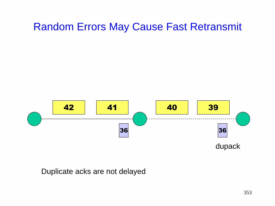
353
Random Errors May Cause Fast Retransmit
42 41 39 40
36
Duplicate acks are not delayed
36
dupack
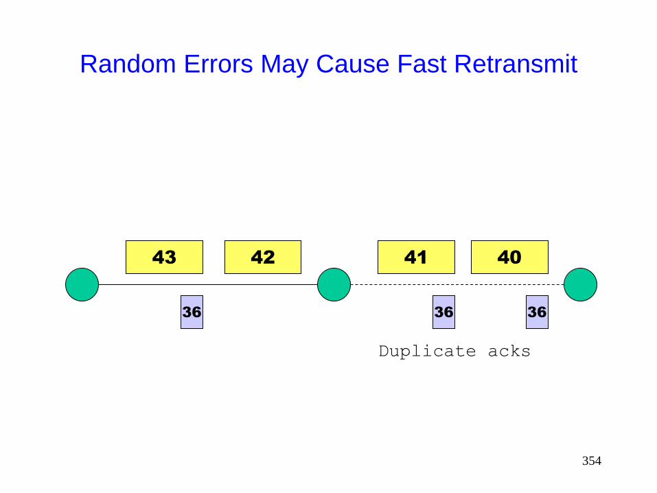
354
Random Errors May Cause Fast Retransmit
40
36 36 36
Duplicate acks
41 43 42
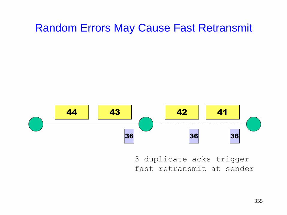
355
Random Errors May Cause Fast Retransmit
41
36 36
3 duplicate acks trigger
fast retransmit at sender
42 44 43
36
356
Random Errors May Cause Fast Retransmit
Fast retransmit results in
retransmission of lost packet
reduction in congestion window
Reducing congestion window in response to errors is
unnecessary
Reduction in congestion window reduces the
throughput

357
Sometimes Congestion Response May be
Appropriate in Response to Errors
On a CDMA channel, errors occur due to interference from other user, and due to noise [Karn99pilc] Interference due to other users is an indication of
congestion. If such interference causes transmission errors, it is appropriate to reduce congestion window
If noise causes errors, it is not appropriate to reduce window
When a channel is in a bad state for a long duration, it might be better to let TCP backoff, so that it does not unnecessarily attempt retransmissions while the channel remains in the bad state [Padmanabhan99pilc]

358
Impact of Random Errors [Vaidya99]
0
400000
800000
1200000
1600000
16384 32768 65536 131072
1/error rate (in bytes)
bits/sec
Exponential error model
2 Mbps wireless full duplex link
No congestion losses
359
Burst Errors May Cause Timeouts
If wireless link remains unavailable for extended
duration, a window worth of data may be lost
driving through a tunnel
passing a truck
Timeout results in slow start
Slow start reduces congestion window to 1 MSS,
reducing throughput
Reduction in window in response to errors
unnecessary

360
Random Errors May Also Cause Timeout
Multiple packet losses in a window can result in
timeout when using TCP-Reno (and to a lesser extent
when using SACK)

361
Impact of Transmission Errors
TCP cannot distinguish between packet losses due to
congestion and transmission errors
Unnecessarily reduces congestion window
Throughput suffers

362
This Tutorial
This tutorial does not consider techniques to improve
TCP performance in presence of transmission errors
Please refer to the Tutorial on TCP for Wireless and
Mobile Hosts presented by Vaidya at MobiCom 1999,
Seattle
The tutorial slides are presently available from
http://www.cs.tamu.edu/faculty/vaidya/ (follow the link to
Seminars)
[Montenegro00-RFC2757] discusses related issues
363
This Tutorial
This tutorial considers impact of multi-hop routes and
route failures due to mobility

364
Mobile Ad Hoc Networks
May need to traverse multiple links to reach a
destination
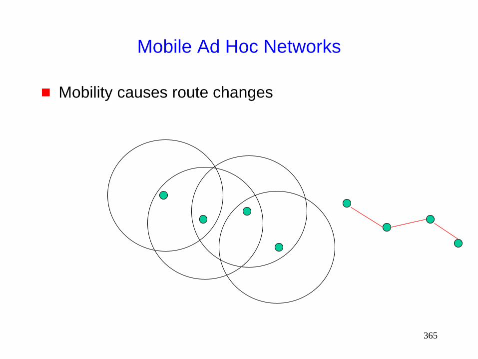
365
Mobile Ad Hoc Networks
Mobility causes route changes
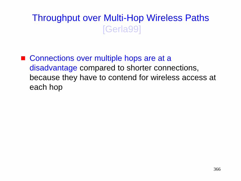
366
Throughput over Multi-Hop Wireless Paths
[Gerla99]
Connections over multiple hops are at a
disadvantage compared to shorter connections,
because they have to contend for wireless access at
each hop

367
Impact of Multi-Hop Wireless Paths
[Holland99]
0
200
400
600
800
1000
1200
1400
1600
1 2 3 4 5 6 7 8 9 10
Number of hops
TCPThroughtput(Kbps)
TCP Throughput using 2 Mbps 802.11 MAC
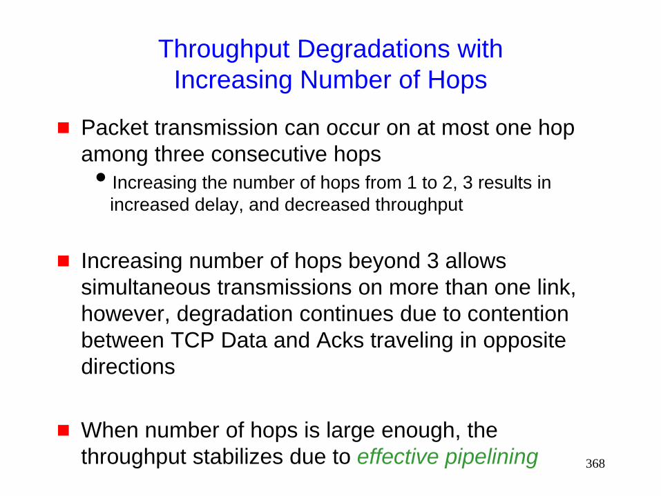
368
Throughput Degradations with
Increasing Number of Hops
Packet transmission can occur on at most one hop
among three consecutive hops
Increasing the number of hops from 1 to 2, 3 results in
increased delay, and decreased throughput
Increasing number of hops beyond 3 allows
simultaneous transmissions on more than one link,
however, degradation continues due to contention
between TCP Data and Acks traveling in opposite
directions
When number of hops is large enough, the
throughput stabilizes due to effective pipelining
369
Ideal Throughput
f(i) = fraction of time for which shortest path length
between sender and destination is I
T(i) = Throughput when path length is I
From previous figure
Ideal throughput = S f(i) * T(i)

370
Impact of Mobility
TCP Throughput
Ideal throughput (Kbps)
2 m/s 10 m/s
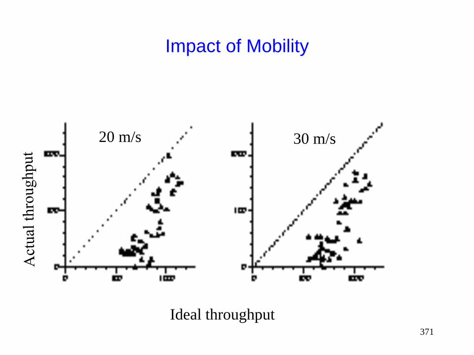
371
Impact of Mobility
Ideal throughput
20 m/s 30 m/s
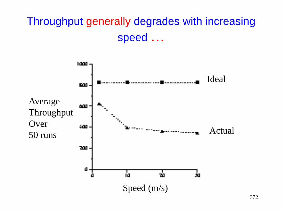
372
Throughput generally degrades with increasing
speed …
Speed (m/s)
Average
Throughput
Over
50 runs
Ideal
Actual

373
But not always …
Mobility pattern #
Actual
throughput
20 m/s
30 m/s
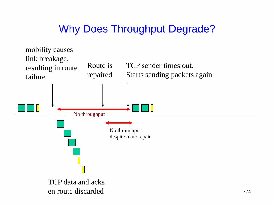
374
mobility causes
link breakage,
resulting in route
failure
TCP data and acks
en route discarded
Why Does Throughput Degrade?
TCP sender times out.
Starts sending packets again
Route is
repaired
No throughput
No throughput
despite route repair

375
mobility causes
link breakage,
resulting in route
failure
TCP data and acks
en route discarded
Why Does Throughput Degrade?
TCP sender
times out.
Backs off timer.
Route is
repaired
TCP sender
times out.
Resumes
sending
Larger route repair delays
especially harmful
No throughput
No throughput
despite route repair

376
Why Does Throughput Improve?
Low Speed Scenario
C
B
D
A
C
B
D
A
C
B
D
A
1.5 second route failure
Route from A to D is broken for ~1.5 second.
When TCP sender times after 1 second, route still broken.
TCP times out after another 2 seconds, and only then resumes.
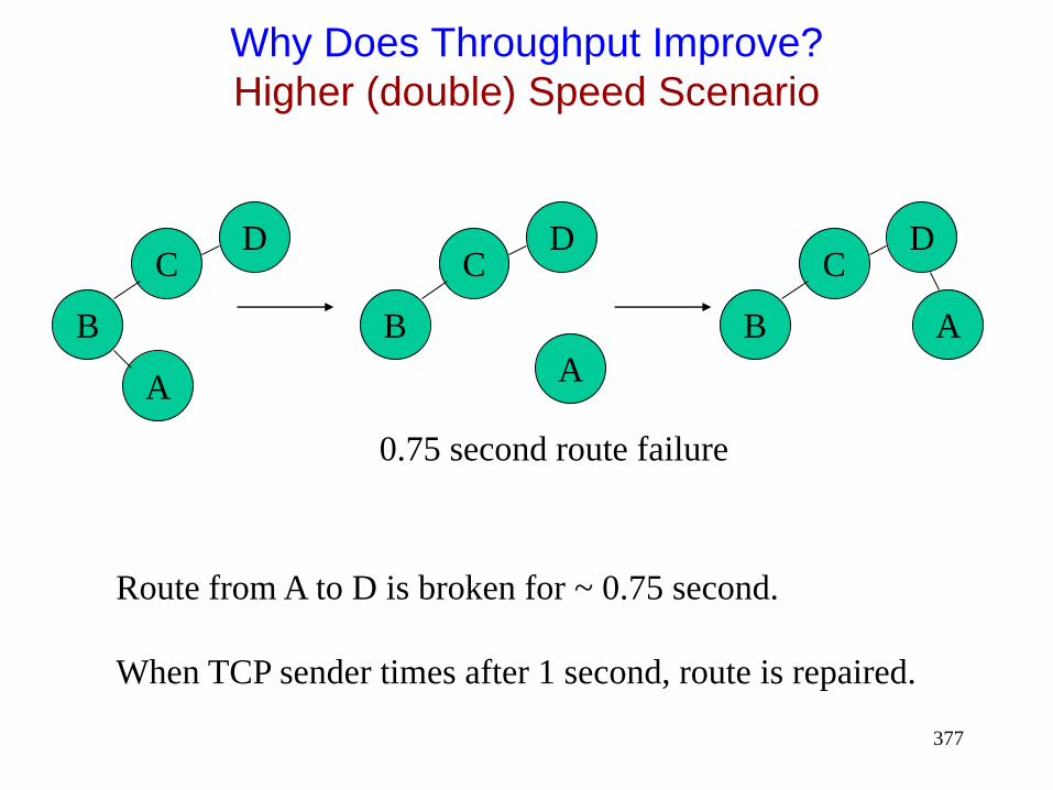
377
Why Does Throughput Improve?
Higher (double) Speed Scenario
C
B
D
A
C
B
D
A
C
B
D
A
0.75 second route failure
Route from A to D is broken for ~ 0.75 second.
When TCP sender times after 1 second, route is repaired.

378
Why Does Throughput Improve?
General Principle
The previous two slides show a plausible cause for improved throughput
TCP timeout interval somewhat (not entirely) independent of speed
Network state at higher speed, when timeout occurs, may be more favorable than at lower speed
Network state Link/route status
Route caches
Congestion
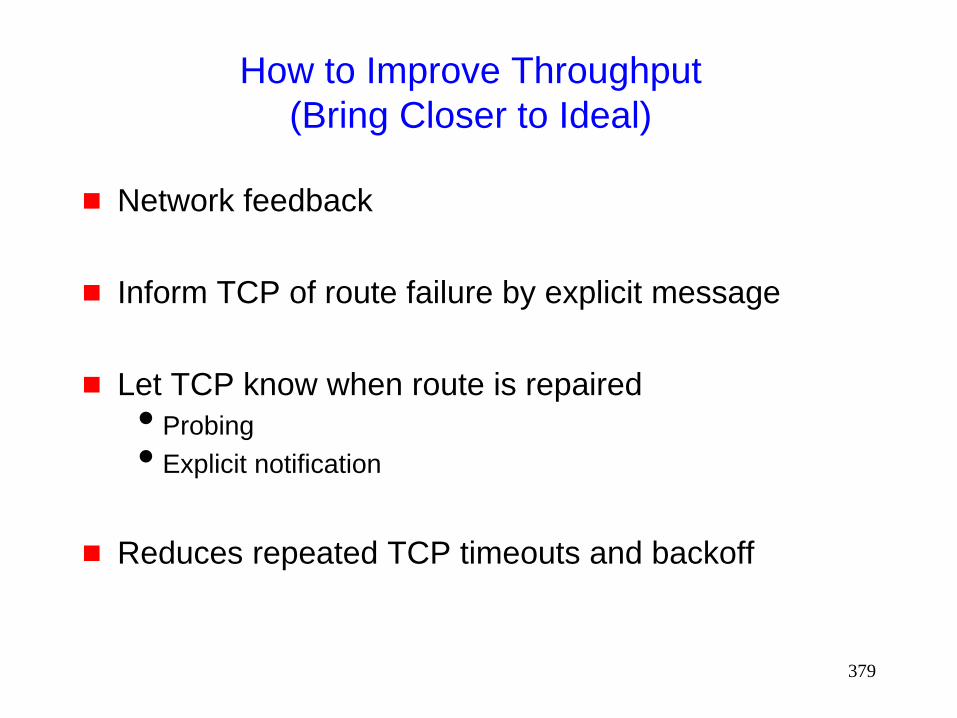
379
How to Improve Throughput
(Bring Closer to Ideal)
Network feedback
Inform TCP of route failure by explicit message
Let TCP know when route is repaired
Probing
Explicit notification
Reduces repeated TCP timeouts and backoff
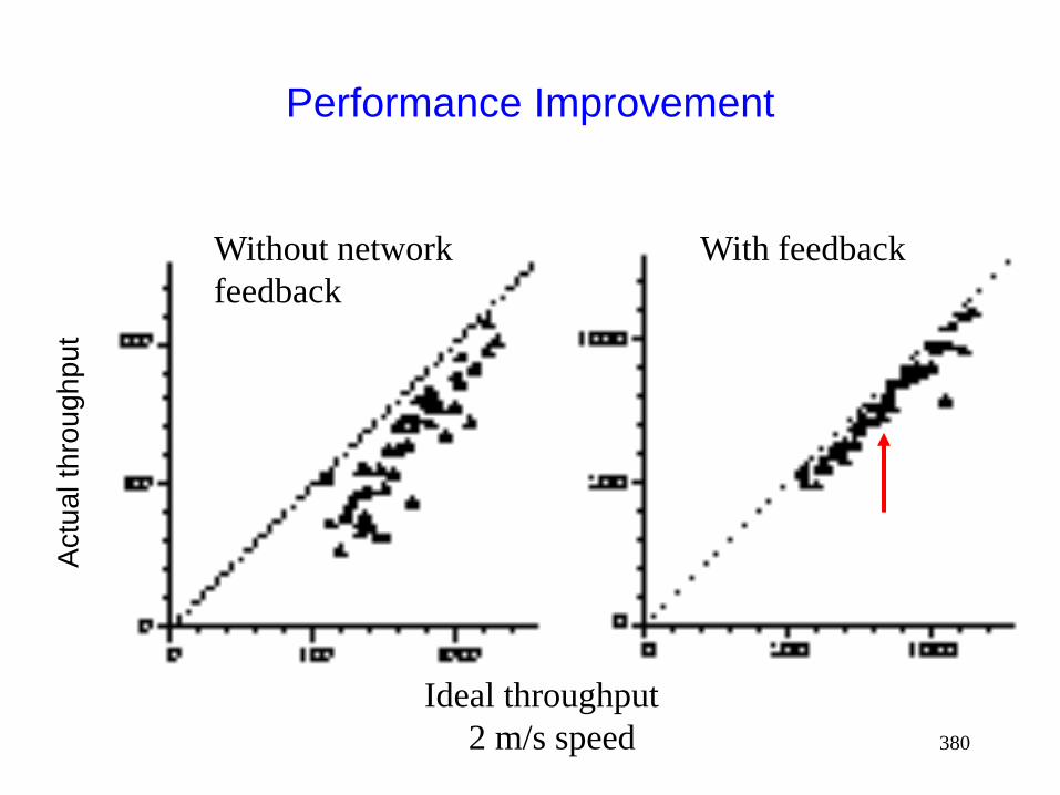
380
Performance Improvement
Without network
feedback
Ideal throughput
2 m/s speed
With feedback
Actu
al th
roughput

381
Performance Improvement
Without network
feedback
With feedback
Ideal throughput
30 m/s speed
Actu
al th
roughput
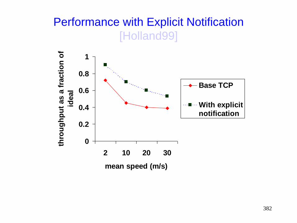
382
Performance with Explicit Notification
[Holland99]
0
0.2
0.4
0.6
0.8
1
2 10 20 30
mean speed (m/s)
thro
ug
hp
ut
as a
fra
cti
on
of
ideal
Base TCP
With explicitnotification

383
Issues
Network Feedback
Network knows best (why packets are lost)
+ Network feedback beneficial
- Need to modify transport & network layer to receive/send feedback
Need mechanisms for information exchange between layers
[Holland99] discusses alternatives for providing feedback (when routes break and repair) [Chandran98] also presents a feedback scheme

384
Impact of Caching
Route caching has been suggested as a mechanism
to reduce route discovery overhead [Broch98]
Each node may cache one or more routes to a given
destination
When a route from S to D is detected as broken,
node S may:
Use another cached route from local cache, or
Obtain a new route using cached route at another node
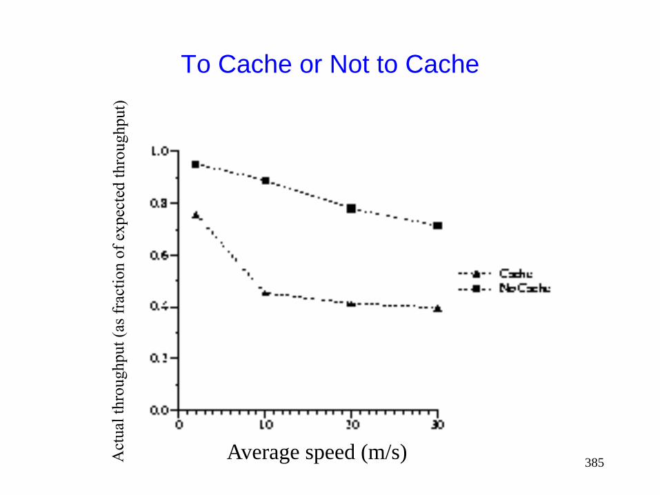
385
To Cache or Not to Cache
Average speed (m/s)

386
Why Performance Degrades With Caching
When a route is broken, route discovery returns a cached route from local cache or from a nearby node
After a time-out, TCP sender transmits a packet on the new route.
However, the cached route has also broken after it was cached
Another route discovery, and TCP time-out interval
Process repeats until a good route is found
timeout due
to route failure
timeout, cached
route is broken timeout, second cached
route also broken

387
Issues
To Cache or Not to Cache
Caching can result in faster route “repair”
Faster does not necessarily mean correct
If incorrect repairs occur often enough, caching
performs poorly
Need mechanisms for determining when cached
routes are stale
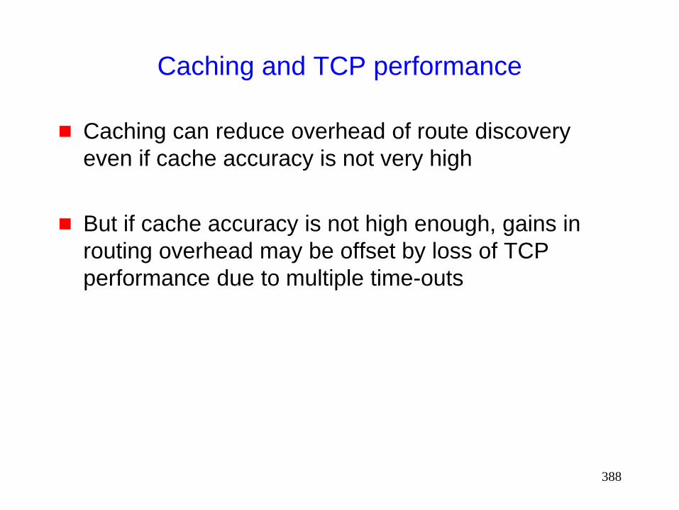
388
Caching and TCP performance
Caching can reduce overhead of route discovery
even if cache accuracy is not very high
But if cache accuracy is not high enough, gains in
routing overhead may be offset by loss of TCP
performance due to multiple time-outs
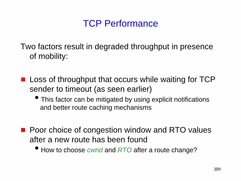
389
TCP Performance
Two factors result in degraded throughput in presence
of mobility:
Loss of throughput that occurs while waiting for TCP
sender to timeout (as seen earlier)
This factor can be mitigated by using explicit notifications
and better route caching mechanisms
Poor choice of congestion window and RTO values
after a new route has been found
How to choose cwnd and RTO after a route change?
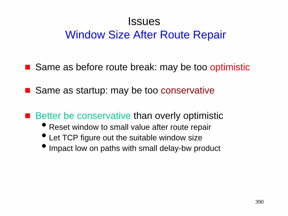
390
Issues
Window Size After Route Repair
Same as before route break: may be too optimistic
Same as startup: may be too conservative
Better be conservative than overly optimistic Reset window to small value after route repair
Let TCP figure out the suitable window size
Impact low on paths with small delay-bw product
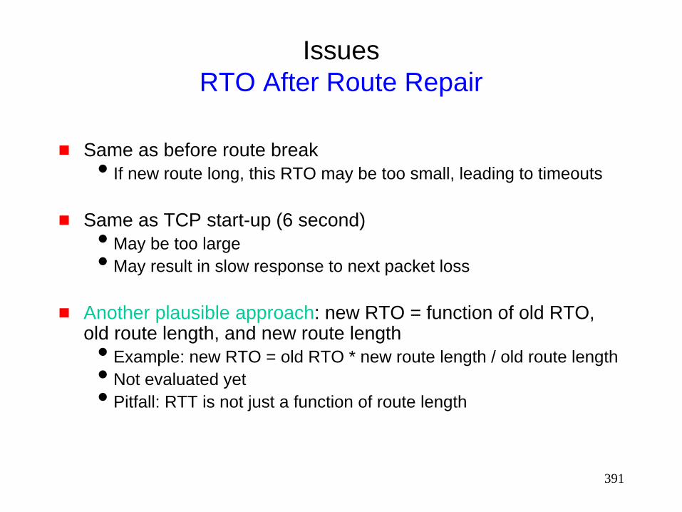
391
Issues
RTO After Route Repair
Same as before route break
If new route long, this RTO may be too small, leading to timeouts
Same as TCP start-up (6 second)
May be too large
May result in slow response to next packet loss
Another plausible approach: new RTO = function of old RTO, old route length, and new route length
Example: new RTO = old RTO * new route length / old route length
Not evaluated yet
Pitfall: RTT is not just a function of route length

392
Out-of-Order Packet Delivery
Out-of-order (OOO) delivery may occur due to:
Route changes
Link layer retransmissions schemes that deliver OOO
Significantly OOO delivery confuses TCP, triggering
fast retransmit
Potential solutions:
Deterministically prefer one route over others, even if
multiple routes are known
Reduce OOO delivery by re-ordering received packets
• can result in unnecessary delay in presence of packet
loss
Turn off fast retransmit
• can result in poor performance in presence of congestion

393
Impact of Acknowledgements
TCP Acks (and link layer acks) share the wireless bandwidth with TCP data packets
Data and Acks travel in opposite directions
In addition to bandwidth usage, acks require additional
receive-send turnarounds, which also incur time penalty
To reduce frequency of send-receive turnaround and
contention between acks and data
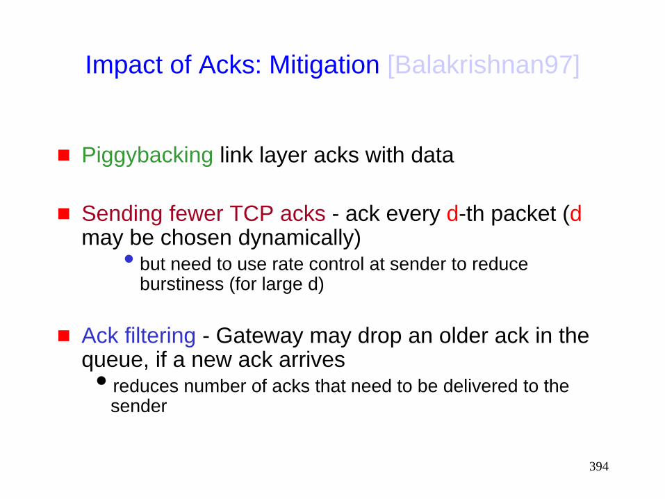
394
Impact of Acks: Mitigation [Balakrishnan97]
Piggybacking link layer acks with data
Sending fewer TCP acks - ack every d-th packet (d may be chosen dynamically)
• but need to use rate control at sender to reduce burstiness (for large d)
Ack filtering - Gateway may drop an older ack in the queue, if a new ack arrives reduces number of acks that need to be delivered to the
sender
395
Security Issues
396
Caveat
Much of security-related stuff is mostly beyond my
expertise
So coverage of this topic is very limited
397
Security Issues in Mobile Ad Hoc Networks
Not much work in this area as yet
Many of the security issues are same as those in
traditional wired networks and cellular wireless
What’s new ?

398
What’s New ?
Wireless medium is easy to snoop on
Due to ad hoc connectivity and mobility, it is hard to
guarantee access to any particular node (for
instance, to obtain a secret key)
Easier for trouble-makers to insert themselves into a
mobile ad hoc network (as compared to a wired
network)
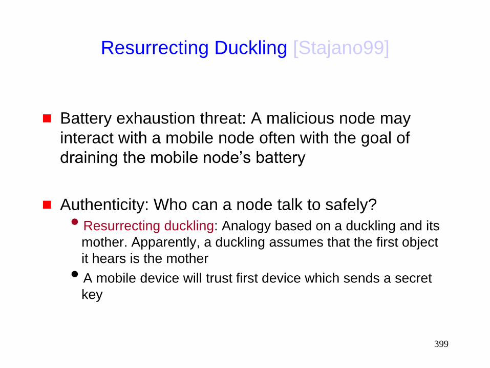
399
Resurrecting Duckling [Stajano99]
Battery exhaustion threat: A malicious node may
interact with a mobile node often with the goal of
draining the mobile node’s battery
Authenticity: Who can a node talk to safely?
Resurrecting duckling: Analogy based on a duckling and its
mother. Apparently, a duckling assumes that the first object
it hears is the mother
A mobile device will trust first device which sends a secret
key
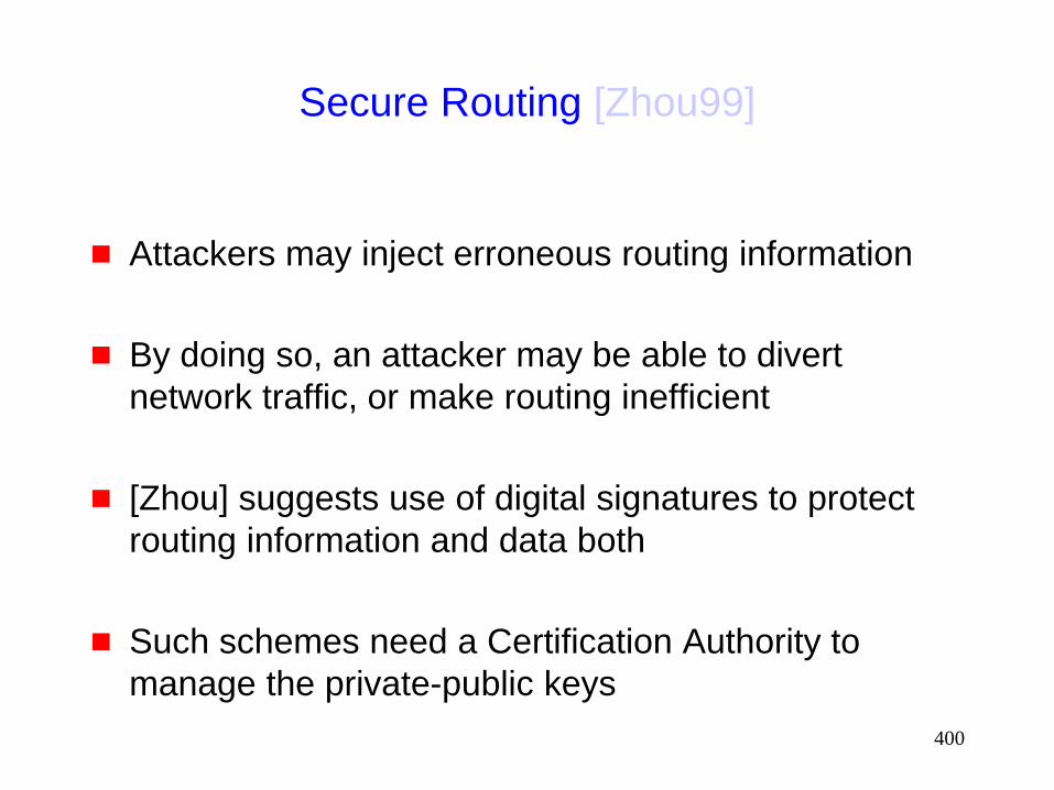
400
Secure Routing [Zhou99]
Attackers may inject erroneous routing information
By doing so, an attacker may be able to divert
network traffic, or make routing inefficient
[Zhou] suggests use of digital signatures to protect
routing information and data both
Such schemes need a Certification Authority to
manage the private-public keys
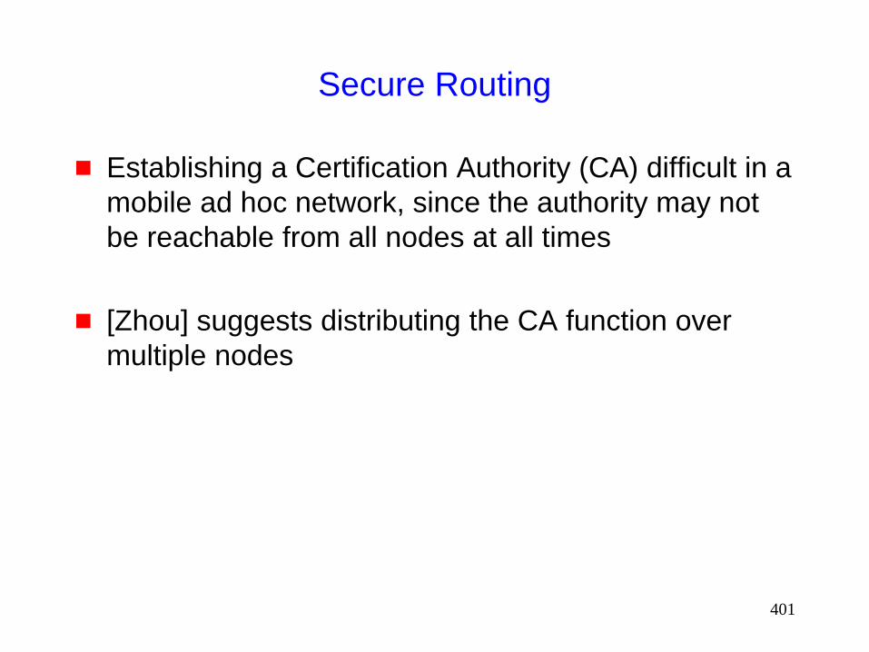
401
Secure Routing
Establishing a Certification Authority (CA) difficult in a
mobile ad hoc network, since the authority may not
be reachable from all nodes at all times
[Zhou] suggests distributing the CA function over
multiple nodes

402
MANET Authentication Architecture
[Jacobs99ietf-id]
Digital signatures to authenticate a message
Key distribution via certificates
Need access to a certification authority
[Jacobs99ietf-id] specifies message formats to be
used to carry signature, etc.

403
Techniques for Intrusion-Resistant Ad Hoc
Routing Algorithms (TIARA) [Ramanujan00Milcom]
Flow disruption attack: Intruder (or compromised)
node T may delay/drop/corrupt all data passing
through, but leave all routing traffic unmodified
A
C B
D
T
intruder

404
Techniques for Intrusion-Resistant Ad Hoc
Routing Algorithms (TIARA) [Ramanujan00Milcom]
Resource Depletion Attack: Intruders may send data
with the objective of congesting a network or
depleting batteries
A
C B
D
T
intruder
U intruder
Bogus traffic

405
Intrusion Detection [Zhang00Mobicom]
Detection of abnormal routing table updates Uses “training” data to determine characteristics of normal
routing table updates (such as rate of change of routing info)
Efficacy of this approach is not evaluated, and is debatable
Similar abnormal behavior may be detected at other protocol layers For instance, at the MAC layer, normal behavior may be
characterized for access patterns by various hosts
Abnormal behavior may indicate intrusion
Solutions proposed in [Zhang00Mobicom] are preliminary, not enough detail provided

406
Preventing Traffic Analysis
[Jiang00iaas,Jiang00tech]
Even with encryption, an eavesdropper may be able
to identify the traffic pattern in the network
Traffic patterns can give away information about the
mode of operation
Attack versus retreat
Traffic analysis can be prevented by presenting
“constant” traffic pattern independent of the
underlying operational mode
May need insertion of dummy traffic to achieve this

407
Packet Purse Model [Byttayn00MobiHoc]
Cost-based approach for motivating collaboration
between mobile nodes
The packet purse model assigns a cost to each
packet transfer
Link-level recipient of a packet pays the link-level sender for
the service
Virtual money (“beans”) used for this purpose
Security issues:
How to ensure that some node does not sale the same
packet to too many people to make money ?
How to ensure that each receiver indeed has money to pay
for service?
408
Implementation Issues
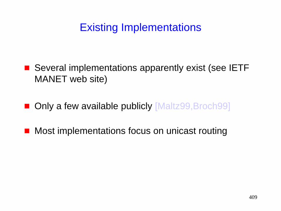
409
Existing Implementations
Several implementations apparently exist (see IETF
MANET web site)
Only a few available publicly [Maltz99,Broch99]
Most implementations focus on unicast routing

410
CMU Implementation [Maltz99]
Physical
devices
Kernel space
Kernel space
WaveLan-I CDPD
User space
IP
TCP/UDP
DSR option processing (RREQ, RREP,…)
Route cache
DSR Output
dsr_xmit
Send
buffer
rexmit
buffer
Route table

411
CMU Implementation: Lessons Learned
Multi-level priority queues helpful: Give higher priority
to routing control packets, and lower for data
If retransmission is implemented above the link layer,
it must be adaptive to accommodate congestion
Since Wavelan-I MAC does not provide retransmissions,
DSR performs retransmits itself
DSR per-hop ack needs to contend for wireless medium
Time to get the ack (RTT) is dependent on congestion
TCP-like RTT estimation and RTO used for triggering
retransmits by DSR on each hop
This is not very relevant when using IEEE 802.11 where the
ack is sent immediately after data reception

412
CMU Implementation: Lessons Learned
“Wireless propagation is not what you would expect”
[Maltz99]
Straight flat areas with line-of-sight connectivity had worst
error rates
“Bystanders will think you are nuts” [Maltz99]
If you are planning experimental studies in the streets, it
may be useful to let police and security guards know in
advance what you are up to

413
BBN Implementation [Ramanathan00Wcnc]
Density and Asymmetric-Adaptive Wireless Network
(DAWN)
Quote from [Ramanathan00Wcnc]: DAWN is a “subnet” or
“link” level system from IP’s viewpoint and runs “below” IP
DAWN
Protocols
Nokia MAC
Utilicom 2050 Radio
Nokia IP Stack
Qos Based Forwarding
=
DAWN IP Gateway
Topology
control
Elastic
Virtual
Circuits
Scalable
Link State
Routing
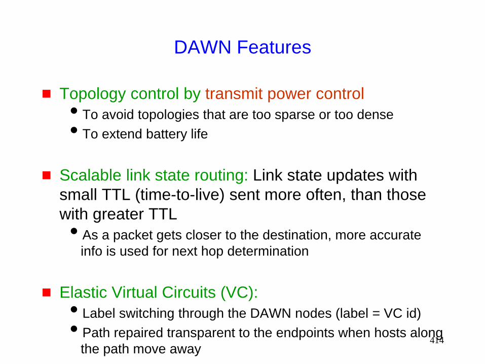
414
DAWN Features
Topology control by transmit power control
To avoid topologies that are too sparse or too dense
To extend battery life
Scalable link state routing: Link state updates with
small TTL (time-to-live) sent more often, than those
with greater TTL
As a packet gets closer to the destination, more accurate
info is used for next hop determination
Elastic Virtual Circuits (VC):
Label switching through the DAWN nodes (label = VC id)
Path repaired transparent to the endpoints when hosts along
the path move away
415
Implementation Issues:
Where to Implement Ad Hoc Routing
Link layer
Network layer
Application layer
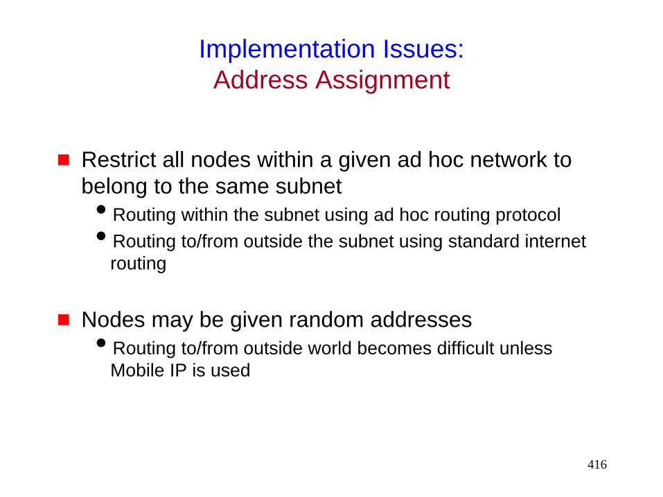
416
Implementation Issues:
Address Assignment
Restrict all nodes within a given ad hoc network to
belong to the same subnet
Routing within the subnet using ad hoc routing protocol
Routing to/from outside the subnet using standard internet
routing
Nodes may be given random addresses
Routing to/from outside world becomes difficult unless
Mobile IP is used
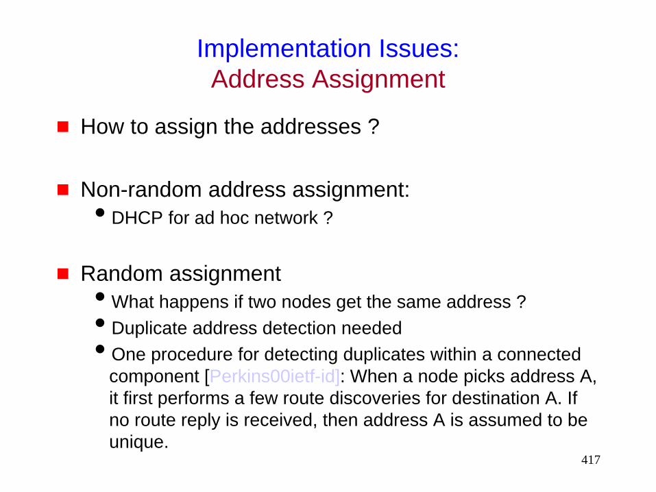
417
Implementation Issues:
Address Assignment
How to assign the addresses ?
Non-random address assignment:
DHCP for ad hoc network ?
Random assignment
What happens if two nodes get the same address ?
Duplicate address detection needed
One procedure for detecting duplicates within a connected
component [Perkins00ietf-id]: When a node picks address A,
it first performs a few route discoveries for destination A. If
no route reply is received, then address A is assumed to be
unique.
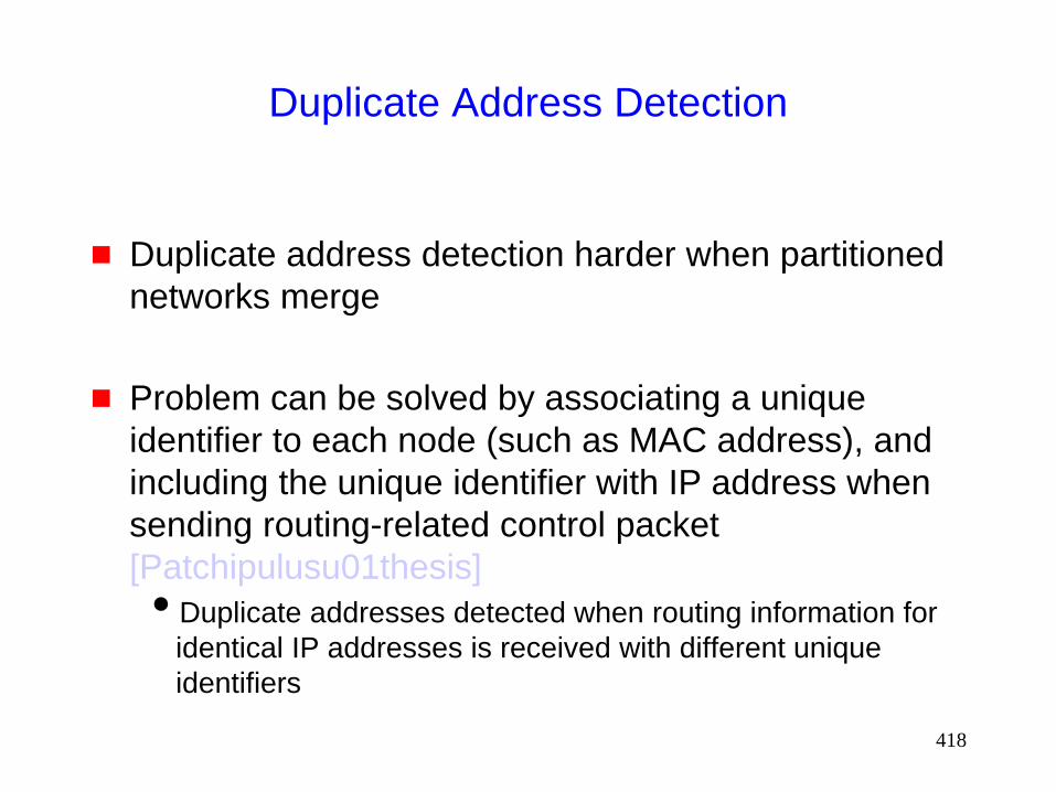
418
Duplicate Address Detection
Duplicate address detection harder when partitioned
networks merge
Problem can be solved by associating a unique
identifier to each node (such as MAC address), and
including the unique identifier with IP address when
sending routing-related control packet
[Patchipulusu01thesis]
Duplicate addresses detected when routing information for
identical IP addresses is received with different unique
identifiers

419
Implementation Issues:
Security
How can I trust you to forward my packets without
tampering?
Need to be able to detect tampering
How do I know you are what you claim to be ?
Authentication issues
Hard to guarantee access to a certification authority
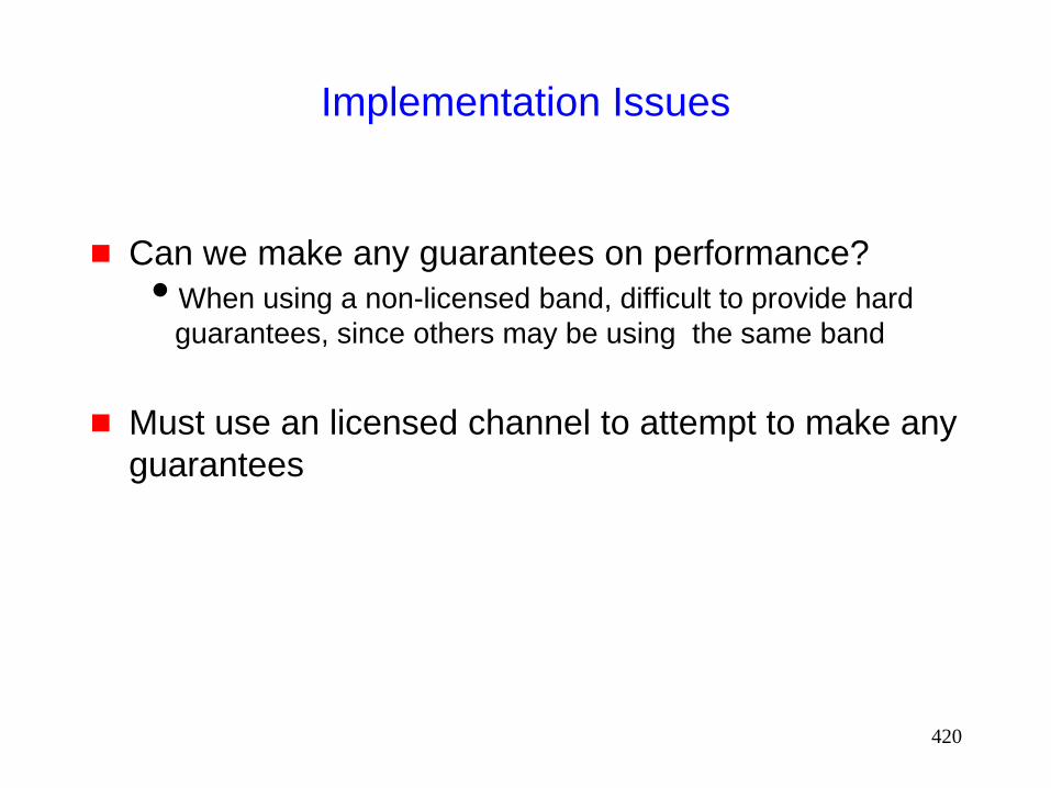
420
Implementation Issues
Can we make any guarantees on performance?
When using a non-licensed band, difficult to provide hard
guarantees, since others may be using the same band
Must use an licensed channel to attempt to make any
guarantees

421
Implementation Issues
Only some issues have been addresses in existing
implementations
Security issues typically ignored
Address assignment issue also has not received
sufficient attention

422
Integrating MANET with the Internet [Broch99]
Mobile IP + MANET routing
At least one node in a MANET should act as a gateway to the rest of the world
Such nodes may be used as foreign agents for Mobile IP
IP packets would be delivered to the foreign agent of a MANET node using Mobile IP. Then, MANET routing will route the packet from the foreign agent to the mobile host.

423
Distributed Algorithms
for
Mobile Ad Hoc Networks

424
Distributed Algorithms
For traditional networks, there is a rich history of work
on distributed algorithms for various problems
including
clock synchronization
mutual exclusion
leader election
Byzantine agreement
….
425
Distributed Algorithms
There is also a large body of work on distributed
algorithms for dynamic networks wherein links may
come up or down [Afek89]
Similarity: Work on dynamic networks is applicable
to ad hoc networks, since both share the dynamic
topology change property
Difference: In ad hoc networks, link failure and
repair caused by the movement of a single node are
likely to be in vicinity of each other, and hence
correlated In dynamic networks research, link events are usually assumed
to be independent

426
Distributed Algorithms: Research Opportunities
Evaluation of existing algorithms for dynamic networks when applied to MANET Identify shortcomings, if any
Design improvements
New distributed algorithms designed for mobile ad hoc networks
Limited research on distributed algorithms designed for MANET. Some examples: Mutual exclusion [Walter98DialM]
Leader election [Royer99Mobicom,Malpani00DialM]
…
427
Related Standards Activities
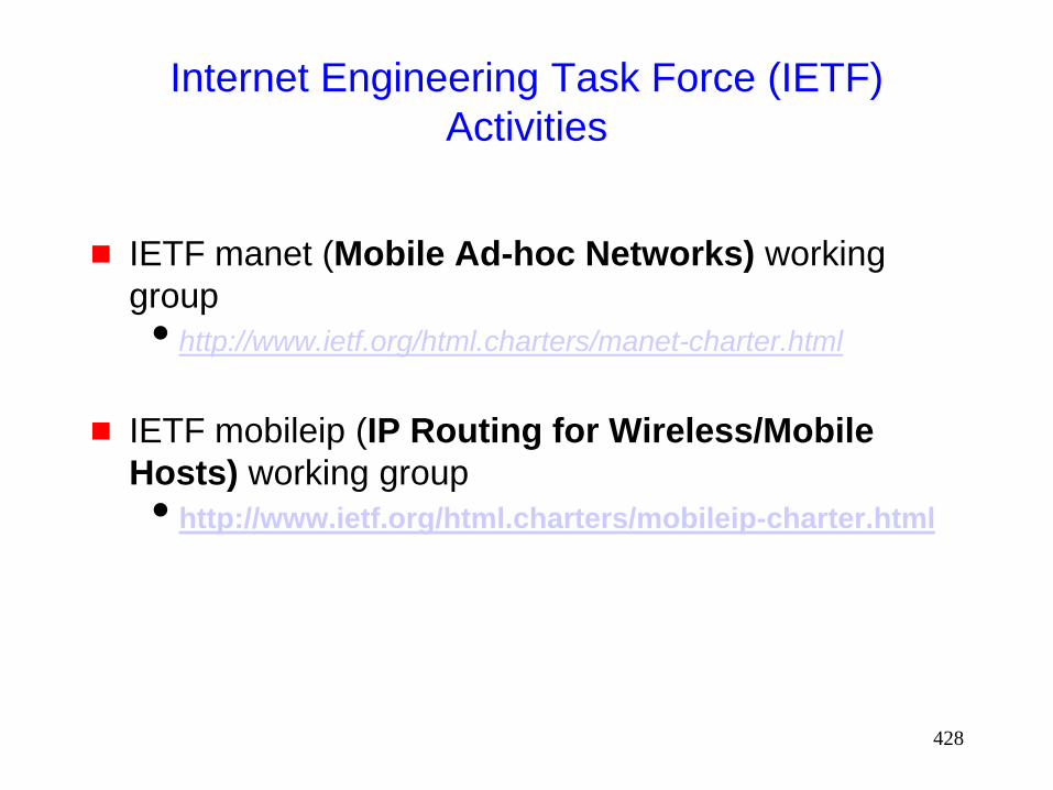
428
Internet Engineering Task Force (IETF)
Activities
IETF manet (Mobile Ad-hoc Networks) working
group
http://www.ietf.org/html.charters/manet-charter.html
IETF mobileip (IP Routing for Wireless/Mobile
Hosts) working group
http://www.ietf.org/html.charters/mobileip-charter.html

429
Internet Engineering Task Force (IETF)
Activities
IETF pilc (Performance Implications of Link
Characteristics) working group
http://www.ietf.org/html.charters/pilc-charter.html
http://pilc.grc.nasa.gov
Refer [RFC2757] for an overview of related work
430
Related Standards Activities
BlueTooth
http://www.bluetooth.com
HomeRF [Lansford00ieee]
http://www.homerf.org
IEEE 802.11
http://grouper.ieee.org/groups/802/11/
Hiperlan/2
http://www.etsi.org/technicalactiv/hiperlan2.htm
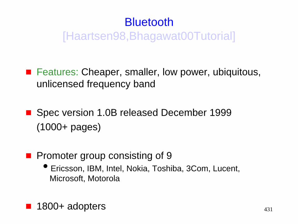
431
Bluetooth
[Haartsen98,Bhagawat00Tutorial]
Features: Cheaper, smaller, low power, ubiquitous,
unlicensed frequency band
Spec version 1.0B released December 1999
(1000+ pages)
Promoter group consisting of 9
Ericsson, IBM, Intel, Nokia, Toshiba, 3Com, Lucent,
Microsoft, Motorola
1800+ adopters
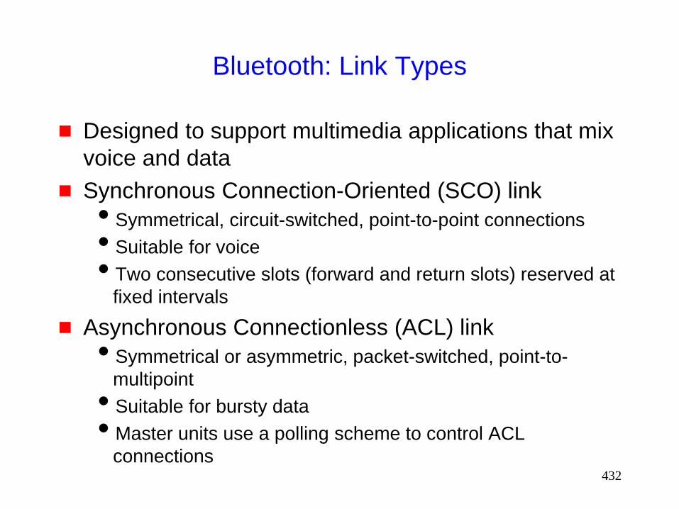
432
Bluetooth: Link Types
Designed to support multimedia applications that mix
voice and data
Synchronous Connection-Oriented (SCO) link
Symmetrical, circuit-switched, point-to-point connections
Suitable for voice
Two consecutive slots (forward and return slots) reserved at
fixed intervals
Asynchronous Connectionless (ACL) link
Symmetrical or asymmetric, packet-switched, point-to-
multipoint
Suitable for bursty data
Master units use a polling scheme to control ACL
connections

433
Bluetooth: Piconet
A channel is characterized by a frequency-hopping
pattern
Two or more terminals sharing a channel form a
piconet
1 Mbps per Piconet
One terminal in a piconet acts as a master and up to
7 slaves
Other terminals are slaves
Polling scheme: A slave may send in a slave-to-
master slot when it has been addressed by its MAC
address in the previous master-to-slave slot
434
Inter-Piconet Communication
A slave can belong to two different piconets, but not
at the same time
A slave can leave its current piconet (after informing
its current master the duration of the leave) and join
another piconet
A maser of one piconet can also join another piconet
temporarily as a slave

435
Bluetooth: Scatternet
Several piconets may exist in the same area (such
that units in different piconets are in each other’s
range)
Each piconet uses a different channel and gets 1
Mbps for the piconet
Since two independently chosen hopping patterns may
select same hop simultaneously with non-zero probability,
some collisions between piconets are possible, reducing
effective throughput
A group of piconets is called a scatternet
436
Routing
Ad hoc routing protocols needed to route between
multiple piconets
Existing protocols may need to be adapted for
Bluetooth [Bhagwat99Momuc]
For instance, not all nodes within transmission range of
node X will hear node X
• Only nodes which belong to node X’s current piconet can
hear the transmission from X
Flooding-based schemes need to take this limitation into
account

437
Open Issues
in
Mobile Ad Hoc Networking

438
Open Problems
Issues other than routing have received much less
attention so far
Other interesting problems:
Address assignment problem
MAC protocols
Improving interaction between protocol layers
Distributed algorithms for MANET
QoS issues
Applications for MANET

439
Related Research Areas
Algorithms for dynamic networks (e.g., [Afek89])
Sensor networks [DARPA-SensIT]
Ad hoc network of sensors
Addressing based on data (or function) instead of name
• “send this packet to a temperature sensor”

440
References
Please see attached listing for the references cited in
the tutorial

441
Thank you !!
For more information, send e-mail to
Nitin Vaidya at
© 2001 Nitin Vaidya