mobile database systems new seminar - 123seminarsonly
TRANSCRIPT

A
Seminar Report
On
SECURITY IN MOBILE DATABASE SYSTEMS
Submitted By :-
Pankaj Menaria
Yash Vyas Kamlesh Jain

A
Seminar Report
On
SECURITY IN MOBILE DATABASE SYSTEMS
In partial fulfillment of requirements for the degree of
Bachelor of Engineering
In
Computer Engineering
SUBMITTED BY:
Pankaj Menaria
Yash Vyas
Kamlesh Jain
Under the Guidance of
Mr. Ajay Prasad
DEPARTMENT OF COMPUTER SCIENCE ENGINEERING

PAGE INDEX
SN Topic
1. INTRODUCTION
1.1 SECURITY IN MOBILE DATABASE
1.2 MOBILE DATABASE
1.3 MOBILE SECURITY
1.4 DATABASE SECURITY
1.5 NEED FOR MOBILE DATABASE
2. MOBILE DATABASE SYSTEMS
2.1 Fully Connected Information Space
2.2 Personal Communication System (PCS)
2.3 Mobile Database Systems (MDS)
2.4 Transaction Management
2.5 Query Processing
2.6 Location and Handoff Management 2.7 Wireless Information Broadcast
3. MOBILE DATABASE SECURITY
3.1 MOBILE CONDITIONS
3.2 PROTECTION OBJECTS AND ACTION
4. CONCLUSION
5. REFERENCES
1. INTRODUCTION
The importance of databases in modern
businesses and governmental institutions is
huge and still growing. Many mission-
critical applications and business processes
rely on databases. These databases contain
data of different degree of importance and
confidentiality, and are accessed by a wide
variety of users. Integrity violations for a
database can have serious impact on business
processes; disclosure of confidential data in
some cases has the same effect. Traditional
database security provides techniques and
strategies to handle such problems with
respect to database servers in a non-mobile
context.
1.1 SECURITY IN MOBILE DATABASE
With the rise in popularity of smartphones
has come an increasing need to secure them.
Since their introduction mobile phones have
becoming increasingly smaller, more
powerful with increasing storage capacity
and have remained expensive items. With the
rise of their popularity so has the need to
secure the devices from theft, as well as
traditional threats that effect computers such
as malware and the need to back and protect
the data on the devices.
Database security is also a specialty within
the broader discipline of computer security.
For many businesses applications are going
mobile that means using enterprise data in a
mobile context, thus using a mobile DBMS.
With these new developments the business
data of an enterprise can be made available
to an even larger number of users and a
wider range of applications than before.
To work on business data anytime and
anywhere is the major goal pursued by
developing mobility support in database
context. The confidentiality of mission-
critical data must be ensured, even though
most mobile devices do not provide a secure
environment for storage of such data.
Security requirements that apply to a central
company database should apply similarly and
in an appropriate manner to the parts of the
database replicated on mobile devices in the
field. A mobile database security
infrastructure is needed to accomplish this
goal. When developing such an infrastructure
we can benefit from the results of traditional
database security work. But we also need to
adapt the existing techniques and strategies
to the mobile context, and we need to
develop new ones that attack certain issues
specific to use of database systems in a
mobile environment.
1.2 MOBILE DATABASE
A mobile database is a database that can be
connected to by a mobile computing device
over a mobile network. The client and server
have wireless connections. A cache is
maintained to hold frequent data and
transactions so that they are not lost due to
connection failure. A database is a structured
way to organize information. This could be a
list of contacts, price information or distance
travelled.
The use of laptops, mobiles and PDAs is
increasing and likely to increase in the
future[citation needed]
with more and more
applications residing in the mobile systems.
While those same analysts can’t tell us
exactly which applications will be the most
popular, it is clear that a large percentage
will require the use of a database of some
sort. Many applications such as databases
would require the ability to download
information from an information repository
and operate on this information even when
out of range or disconnected.
An example of this is a mobile workforce. In
this scenario user would require to access
and update information from files in the
home directories on a server or customer
records from a database. This type of access
and work load generated by such users is
different from the traditional workloads seen
in client–server systems of today. With the
advent of mobile databases, now users can
load up their smart phones or PDAs with
mobile databases to exchange mission-
critical data remotely without worrying about
time or distance. Mobile databases let
employees enter data on the fly. Information
can be synchronized with a server database at
a later time.
1.3 MOBILE SECURITY
With the rise in popularity of smartphones
has come an increasing need to secure them.
Since their introduction mobile phones have
becoming increasingly smaller, more
powerful with increasing storage capacity
and have remained expensive items. With the
rise of their popularity so has the need to
secure the devices from theft, as well as
traditional threats that effect computers such
as malware and the need to back and protect
the data on the devices.
A recent report from McAfee titled" 2011
Threats Predictions", outlines the company’s
concerns about the changing ―threats
landscape‖ thanks in part to increases in
malware sophistication and targeting and
how they relate to seven areas — including
social media, mobile Apple-related products
and applications.
Although viruses are a key concern, the
actual number of viruses targeting mobile
phones in the wild has not been widespread.
1.4 DATABASE SECURITY
Database security is the system, processes,
and procedures that protect a database from
unintended activity. Unintended activity can
be categorized as authenticated misuse,
malicious attacks or inadvertent mistakes
made by authorized individuals or processes.
Traditionally databases have been protected
from external connections by firewalls or
routers on the network perimeter with the
database environment existing on the internal
network opposed to being located within a
demilitarized zone. Additional network
security devices that detect and alert on
malicious database protocol traffic include
network intrusion detection systems along
with host-based intrusion detection systems.
Database security is more critical as
networks have become more open.
Databases provide many layers and types of
information security, typically specified in
the data dictionary, including:
Access control
Auditing
Authentication
Encryption
Integrity controls
1.5 NEED FOR MOBILE DATABASE
Mobile users must be able to work
without a wireless connection due to
poor or even non-existent connections.
Applications must provide significant
interactivity.
Applications must be able to access
local device/vehicle hardware, such as
printers, bar code scanners, or GPS
units (for mapping or Automatic
Vehicle Location systems).
Bandwidth must be conserved (a
common requirement on wireless
networks that charge per megabyte or
data transferred).
Users don't require access to truly live
data, only recently modified data.

Limited life of power supply(battery)
The changing topology of network
If your application meets any of those
requirements, the chances are good that you
will be required to build a mobile database
application with synchronization.
Mobile database system architecture
For any mobile architecture, things to be
considered are:
Users are not attached to a fixed
geographical location
Mobile computing devices: low-power,
low-cost, portable
Wireless networks
Mobile computing constraints
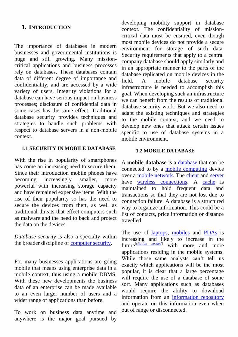
1) Three parties
Mobile databases typically involve three
parties: fixed hosts, mobile units, and base
stations. Fixed hosts perform the transaction
and data management functions with the help
of database servers. Mobile units are portable
computers that move around a geographical
region that includes the cellular network (or
"cells") that these units use to communicate
to base stations. (Note that these networks
need not be cellular telephone networks.)
Base stations are two-way radios,
installations in fixed locations, that pass
communications with the mobile units to and
from the fixed hosts. They are typically low-
power devices such as mobile phones,
portable phones, or wireless routers.
When a mobile unit leaves a cell serviced by
a particular base station, that station
transparently transfers the responsibility for
the mobile unit's transaction and data support
to whichever base station covers the mobile
unit's new location.
2) Products
Sybase Inc.’s SQL Anywhere dominates the
mobile-database field, with about 68 percent
of the mobile database market. IBM’s DB2
Everyplace is a relational database and
enterprise synchronization server that
extends enterprise applications to mobile
devices. Microsoft SQL Server Compact and
Oracle9i Lite are similar mobile databases.
Products from lesser-known vendors, such as
SQLBase from Gupta Technologies LLC of
Redwood Shores, Calif., HanDBase from
DDH Software Inc. of Lake Worth, Fla.and
Database Viewer Plus from Cellica
Corporation NY, might serve your needs
equally well.
3) Sybase's SQL Anywhere
SQL Anywhere offers enterprise-caliber
databases that scale from 64-bit servers with
thousands of users down to small handheld
devices. SQL Anywhere’s data exchange
technologies extend information in corporate
applications and enterprise systems to
databases running in mission-critical
frontline environments. Design and
management tools within SQL Anywhere
enable developers to implement and deploy
frontline applications and equip
administrators to easily manage and support
them.
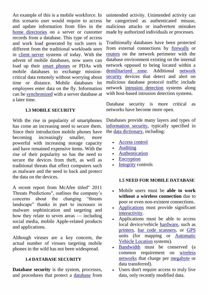
4) SQL Anywhere Technologies
SQL Anywhere Server is a high performing
and embeddable relational database-
management system (RDBMS) that scales
from thousands of users in server
environments down to desktop and mobile
applications used in widely deployed, zero-
administration environments.
Ultralite: UltraLite is a database-
management system designed for small-
footprint mobile devices such as PDAs and
smart phones.
Mobilink: MobiLink is a highly-scalable,
session-based synchronization technology for
exchanging data among relational databases
and other non-relational data sources.
QAnywhere: QAnywhere facilitates the
development of robust and secure store-and-
forward mobile messaging applications.
SQL Remote: SQL Remote technology is
based on a store and forward architecture that
allows occasionally connected users to
synchronize data between SQL Anywhere
databases using a file or message transfer
mechanism.
5) IBM DB2 Everyplace (DB2e)
DB2e stores, retrieves, organizes and
manages data on a handheld device. The data
on the handheld device is synchronized to a
server-based relational database management
system (RDMS). DB2e is currently available
for Palm OS, EPOC, Neutrino, Windows CE
and embedded Linux DB2e on the handheld
device includes:
IBM DB2 Database Engine
IBM Sync
Query By Example (QBE)
DB2e includes a component called
Synchronization Server, which:
Allows synchronization between DB2e
and server database
Mobile Device Administration Center
(MDAC)
Table encryption for version 8.1.1
Java ME Sync Client for cell phones
and pagers
6) Microsoft SQL Server Compact
(formerly SQL Server 2005 Mobile
Edition)
Microsoft SQL Server Compact (SSC) is a
small footprint embedded database designed
for developers who target Microsoft
Windows mobile-based devices or desktops.
It provides synchronization with Microsoft
SQL Server, programming APIs, integrated
development experience through Visual
Studio and a Management Studio.
7) Oracle9i Lite
This is a complete solution for mobile or
wireless applications that require the use of a
relational database on the mobile client. It
includes support for Win32, Windows CE,
PalmOS, and EPOC database clients,
integration with Oracle's Advanced Queuing
(AQ) mechanism, and data and application
synchronization software (to enterprise
Oracle databases. The Oracle9i Lite
relational database is surprisingly[citation needed]
powerful. The database supports 100% Java
development (through JDBC drivers and the
database's native support for embedded SQLJ
and Java stored procedures) as well as
programming from any development tool
that supports ODBC (Visual Basic, C++,
Delphi, and so on).
8) Others
Borland's JDataStore
Borland JDataStore 6 is a fast, versatile Java
database for truly portable embedded,
mobile, and Web server applications.
Compliant with Java and SQL92 standards,
the JDataStore database features a very small
footprint, requires practically zero
maintenance, and delivers the performance,
scalability, and synchronization capabilities
of a full-power database.
MobiSnap
MobiSnap, a research project that aims to
support the development of SQL based
applications for mobile environments,
providing conquerable support for data
divergence control and connectivity
abstractions. MobiSnap aims at developing a
middle-ware infrastructure that allows access
to relational database systems from mobile
computers with a clear semantics in all
operational scenarios (from high to
unavailable connectivity). This platform will
isolate programmers from the problems
related to mobility and disconnection,
allowing them to easily develop new
applications for mobile environments,
focusing only on application specific
problems. MobiSnap will be based on SQL,
thereby also providing close integration to
legacy information systems.

2. MOBILE DATABASE
SYSTEMS
2.1 Fully Connected Information Space
Each node of the information space has
some communication capability.
Some node can process information.
Some node can communicate through
voice channel.
Some node can do both
Can be created and maintained by integrating
legacy database systems, and wired and
wireless systems (PCS, Cellular system, and
GSM)

2.2 Personal Communication System (PCS)
A system where wired and wireless networks are integrated for establishing communication.
PCS refers to variety of wireless access
(communication) and personal mobility
services provided through a small terminal at
any place, and in any form. Business
opportunities (E-commerce) for such
services are tremendous, since every person,
every organization, etc., could be equipped.
Several PCS systems have been developed to
meet rapid growth prompted by market
demand. Most of them are connected to
Public Switched Telephone Network (PSTN)
to integrate with the wired service.
Two of the most popular PCS systems
are:
Cellular telephony
Cordless and low-tier PCS telephony
Cellular telephony overview
Four popular cellular telephony networks
are:
Advanced Mobile Phone Service (AMPS)
Global System for Mobile
Communication (GSM)
EIA/TIA IS-136 Digital Cellular System
EIA/TIA IS-95 Digital Cellular System
Advanced Mobile Phone Service (AMPS)
AMPS was the first cellular system, which
was developed during the 1970s by Bell Lab.
From 1974 to 1978, a large scale AMPS trial
was conducted in Chicago. Commercial
AMPS service has been available since 1983.
It is based on frequency division multiple
access (FDMA), AMP was designed as a
high capacity system based on a frequency
PSTN: Public Switched Network.
MSC: Mobile Switching Center. Also called MTSO
(Mobile Telephone Switching Office).
BS: Base Station.
MS: Mobile Station. Also called MU (Mobile Unit)
or Mobile Host (MH).
HLR: Home Location Register.
VLR: Visitor Location Register.
EIR: Equipment Identify Register.
AC: Access Chanel.
PSTN
BS
VLR
HLR
EIR
AC
MSC (MTSO)MSC (MTSO)
MSMS Wireless component
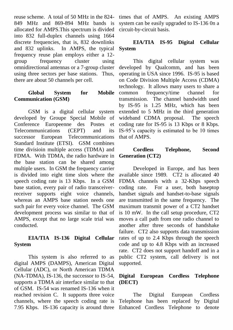
reuse scheme. A total of 50 MHz in the 824-
849 MHz and 869-894 MHz bands is
allocated for AMPS.This spectrum is divided
into 832 full-duplex channels using 1664
discrete frequencies, that is, 832 downlinks
and 832 uplinks. In AMPS, the typical
frequency reuse plan employs either a 12-
group frequency cluster using
omnidirectional antennas or a 7-group cluster
using three sectors per base stations. Thus,
there are about 50 channels per cell.
Global System for Mobile
Communication (GSM)
GSM is a digital cellular system
developed by Groupe Special Mobile of
Conference Europeenne des Postes et
Telecommunications (CEPT) and its
successor European Telecommunications
Standard Institute (ETSI). GSM combines
time divisioin multiple access (TDMA) and
FDMA. With TDMA, the radio hardware in
the base station can be shared among
multiple users. In GSM the frequency carrier
is divided into eight time slots where the
speech coding rate is 13 Kbps. In a GSM
base station, every pair of radio transceiver-
receiver supports eight voice channels,
whereas an AMPS base station needs one
such pair for every voice channel. The GSM
development process was similar to that of
AMPS, except that no large scale trial was
conducted.
EIA/TIA IS-136 Digital Cellular
System
This system is also referred to as
digital AMPS (DAMPS), American Digital
Cellular (ADC), or North American TDMA
(NA-TDMA), IS-136, the successor to IS-54,
supports a TDMA air interface similar to that
of GSM. IS-54 was renamed IS-136 when it
reached revision C. It supports three voice
channels, where the speech coding rate is
7.95 Kbps. IS-136 capacity is around three
times that of AMPS. An existing AMPS
system can be easily upgraded to IS-136 0n a
circuit-by-circuit basis.
EIA/TIA IS-95 Digital Cellular
System
This digital cellular system was
developed by Qualcomm, and has been
operating in USA since 1996. IS-95 is based
on Code Division Multiple Access (CDMA)
technology. It allows many users to share a
common frequency/time channel for
transmission. The channel bandwidth used
by IS-95 is 1.25 MHz, which has been
extended to 5 MHz in the third generation
wideband CDMA proposal. The speech
coding rate for IS-95 is 13 Kbps or 8 Kbps.
IS-95’s capacity is estimated to be 10 times
that of AMPS.
Cordless Telephone, Second
Generation (CT2)
Developed in Europe, and has been
available since 1989. CT2 is allocated 40
FDMA channels with a 32-Kbps speech
coding rate. For a user, both baseptop
handset signals and handset-to-base signals
are transmitted in the same frequency. The
maximum transmit power of a CT2 handset
is 10 mW. In the call setup procedure, CT2
moves a call path from one radio channel to
another after three seconds of handshake
failure. CT2 also supports data transmission
rates of up to 2.4 Kbps through the speech
code and up to 4.8 Kbps with an increased
rate. CT2 does not support handoff and in a
public CT2 system, call delivery is not
supported.
Digital European Cordless Telephone
(DECT)
The Digital European Cordless
Telephone has been replaced by Digital
Enhanced Cordless Telephone to denote

global acceptance of DECT. DECT supports
high user density with a picocell design.
There are 12 voice channels per frequency
carrier. Sleep mode is employed to converse
handset power. DECT also supports
seamless handoff. DECT is typically
implemented as a wireless-PBX (Private
Brach Exchange) connected to PSTN.
DECT can interwork with GSM to allow user
mobility.
Low-tier PCS telephony overview
Personal Handy Phone System
(PHS)
PHS is a standard developed by the
Research and Development Center for Radio
Systems (RCR), a private standardization
organization in Japan. PHS is a low-tier
digital PCS system that offers
telecommunication services for homes,
offices, and outdoor environment, using
radio access to the public telephone network
or other digital networks. PHS uses TDMA.
Sleep mode enables PHS to support five
hours of talk time, or 150 hours of standby
time. PHS operates in the 1895-1918.1 MHz
band. The bandwidth is partitioned into 77
channels, each with 300 KHz bandwidth.
The band 1906.1-1918.1 MHz (40 channels)
is designed for public systems, and the band
1895-1906.1 MHz (37 channels) is used for
home/office applications.
Personal Access Communications
Systems (PACS)
PACS is a low-power PCS system
developed at Telcordia (formerly Bellcore).
TDMA is used in PACS with eight voice
channels per frequency carrier. In FDD
mode, the PACS uplink and downlink
utilizes different RF carriers, similar to
cellular systems.
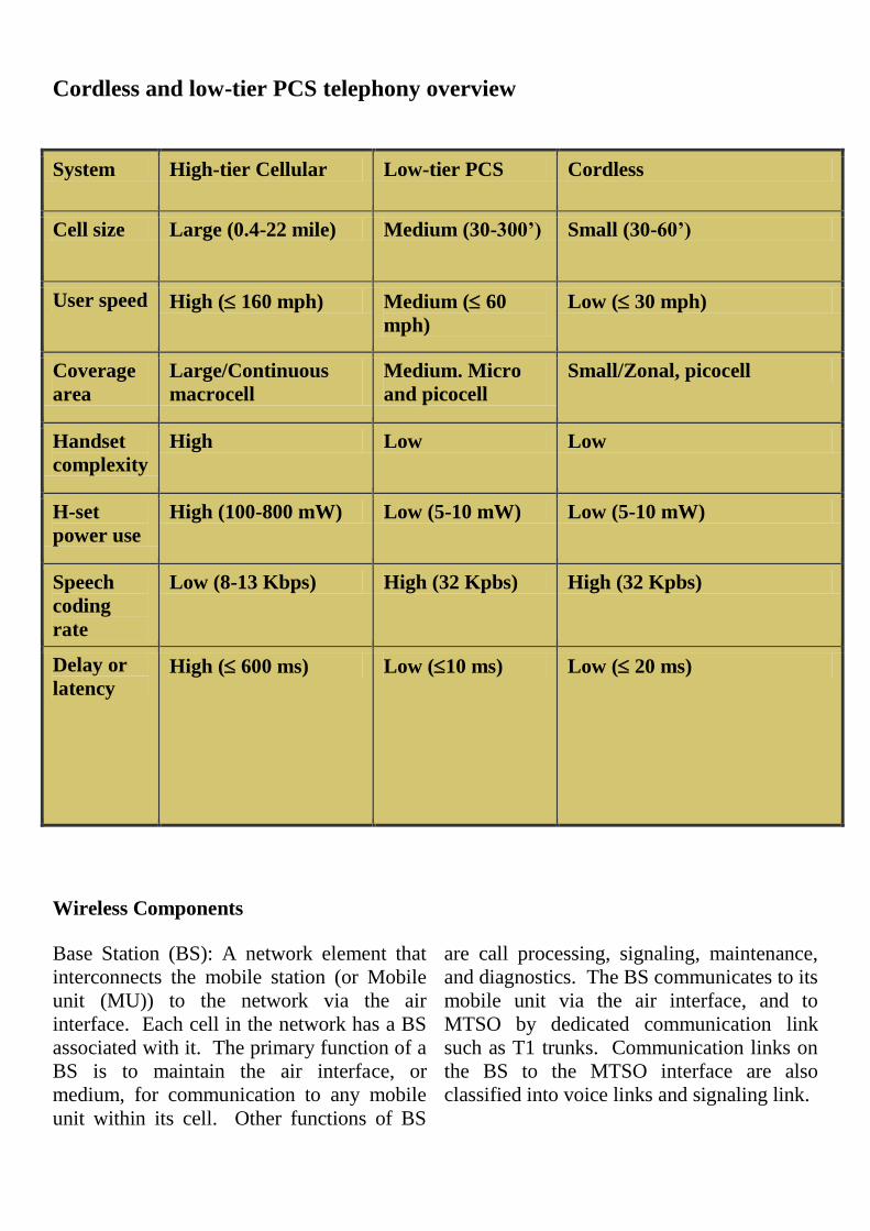
Cordless and low-tier PCS telephony overview
System High-tier Cellular Low-tier PCS Cordless
Cell size Large (0.4-22 mile) Medium (30-300’) Small (30-60’)
User speed High ( 160 mph) Medium ( 60
mph)
Low ( 30 mph)
Coverage
area
Large/Continuous
macrocell
Medium. Micro
and picocell
Small/Zonal, picocell
Handset
complexity
High Low Low
H-set
power use
High (100-800 mW) Low (5-10 mW) Low (5-10 mW)
Speech
coding
rate
Low (8-13 Kbps) High (32 Kpbs) High (32 Kpbs)
Delay or
latency High ( 600 ms) Low (10 ms) Low ( 20 ms)
Wireless Components
Base Station (BS): A network element that
interconnects the mobile station (or Mobile
unit (MU)) to the network via the air
interface. Each cell in the network has a BS
associated with it. The primary function of a
BS is to maintain the air interface, or
medium, for communication to any mobile
unit within its cell. Other functions of BS
are call processing, signaling, maintenance,
and diagnostics. The BS communicates to its
mobile unit via the air interface, and to
MTSO by dedicated communication link
such as T1 trunks. Communication links on
the BS to the MTSO interface are also
classified into voice links and signaling link.

Mobile Units (MU):
Also called Mobile Systems (MS) or Mobile
Hosts (MH). It consists of three components:
(a) transceiver, (b) antenna, and (c) user
interface. The user interface exists only at
MU, which consists of a display, a keypad
for entering information, and an audio
interface for speaking and hearing voice
conversation. This can be a laptop, a
palmtop, or a cell phone, or any other mobile
device. A MU also stores (a) Mobile
Identification Number (MIN), (b) Electronic
Serial Number (EIN), and (C) Station Class
Mark (SCM). These are transmitted upon
power on, cell initiated sampling, and cell
origination.
Mobile cell
Within the cellular allocation the USA
is divided into Metropolitan Statistical
Areas (MSAs) and Rural Statistical
Areas (RSAs). There are six PCS
service providers authorized to provide
mobile service in each of these areas.
Within their geographical region, each
service provider divides their area into
smaller segments called cells. Each of
this cell has a Base Station. Ideally,
the system has a large number of very
small hexagons (cell). The greater the
number of hexagons, the more
simultaneous calls the system can
handle. However, larger number of
hexagons increases the cost of
implementation. Thus, cell coverage
is a dynamic activity, which is
constantly changing in response to
increases in demand.
BS
MSC (MTSO)
MS Wireless
componentMS
Cell

The entire coverage area is a group of a number of cells. The size of cell depends upon the
power of the base stations.
Metropolitan area Metropolitan area
Coverage area in one cell Coverage area in three cells
BS
BS
BSBase Station
Large cells.
Low density
Small cells.
High density
Smaller cells.
Higher density
PSTNMSC
Problems with cellular structure
How to maintain continuous
communication between two parties in the
presence of mobility?
Solution: Handoff
How to maintain continuous
communication between two parties in the
presence of mobility?
Solution: Roaming
How to locate of a mobile unit in the
entire coverage area?
Solution: Location management
Roaming
Roaming is a facility, which allows a
subscriber to enjoy uninterrupted
communication from anywhere in the entire
coverage space.
A mobile network coverage space may
be managed by a number of different service
providers. They must cooperate with each
other to provide roaming facility.
Roaming can be provided only if some
administrative and technical constraints are
met.
Administrative constraints
Billing.
Subscription agreement.
Call transfer charges.
User profile and database sharing.
Any other policy constraints.
Technical constraints
Bandwidth mismatch. For example,
European 900MHz band may not be
available in other parts of the world. This
may preclude some mobile equipment for
roaming.
Service providers must be able to
communicate with each other. Needs
some standard.
Mobile station constraints.
Integration of a new service provider
into the network. A roaming
subscriber must be able to detect this
new provider.
Service providers must be able to
communicate with each other. Needs
some standard.
Quick MU response to a service
provider’s availability.
Limited battery life.
Two basic operations in roaming
management are
Registration (Location update): The
process of informing the presence or arrival
of a MU to a cell.
Location tracking: the process of
locating the desired MU.
Registration (Location update): There are six
different types of registration.
Power-down registration. Done by the
MU when it intends to switch itself
off.
Power-up registration. Opposite to
power-down registration. When an
MU is switched on, it registers.
Deregistration. A MU decides to
acquire control channel service on a
different type of network (public,
private, or residential).
Registration (Location update): There are six
different types of registration.
New system/Location area
registration: when the location area of
the MU changes, it sends a registration
message.
Periodic registration: A MU may be
instructed to periodically register with
the network.
Forced registration: A network may,
under certain circumstances, force all
MUs to register.
2.3 Mobile Database Systems (MDS)
What is a Mobile Database System
(MDS)?
A system with the following structural
and functional properties
Distributed system with mobile
connectivity
Full database system capability
Complete spatial mobility
Built on PCS/GSM platform
Wireless and wired communication
capability
MDS Applications
Insurance companies
Emergencies services (Police, medical,
etc.)
Traffic control
Taxi dispatch
E-commerce
Etc.
MDS Limitations
Limited wireless bandwidth
Wireless communication speed
Limited energy source (battery power)
Less secured
Vulnerable to physical activities
Hard to make theft proof.
MDS capabilities
Can physically move around without
affecting data availability Can reach to
the place data is stored
Can process special types of data
efficiently
Not subjected to connection restrictions
Very high reachability
Highly portable
To build a truly ubiquitous information
processing system by overcoming the
inherent limitations of wireless architecture
MDS Issues
Data Management
Data Caching
Data Broadcast (Broadcast disk)
Data Classification
Transaction Management
Query processing
Transaction processing
Concurrency control
Database recovery

A Reference Architecture (Client-Server model)
MDS Data Management Issues
How to improve data availability to user
queries using limited bandwidth?
Possible schemes
Semantic data caching: The cache
contents is decided by the results of
earlier transactions or by semantic
data set.
Data Broadcast on wireless channels
Semantic caching
Client maintains a semantic
description of the data in its cache
instead of maintaining a list of pages
or tuples.
The server processes simple predicates
on the database and the results are
cached at the client.
Data Broadcast (Broadcast disk)
A set of most frequently accessed data is
made available by continuously
broadcasting it on some fixed radio
frequency. Mobile Units can tune to this
frequency and download the desired data
from the broadcast to their local cache. A
broadcast (file on the air) is similar to a
disk file but located on the air. The
contents of the broadcast reflects the data
demands of mobile units. This can be
achieved through data access history,
which can be fed to the data broadcasting
system. For efficient access the broadcast
file use index or some other method.
How MDS looks at the database data?
Data classification
Location Dependent Data (LDD)
Location Independent Data (LID)
Location Dependent Data (LDD)
The class of data whose value is functionally
dependent on location. Thus, the value of
the location determines the correct value of
the data.
Location Data value
Examples: City tax, City area, etc.
MSC MSC
DB DB HLR VLR
BSC BSC
DBS DBS
MU BS
MU
MU
BS
MU
BS
MU
Fixed host
Fixed host
PSTN
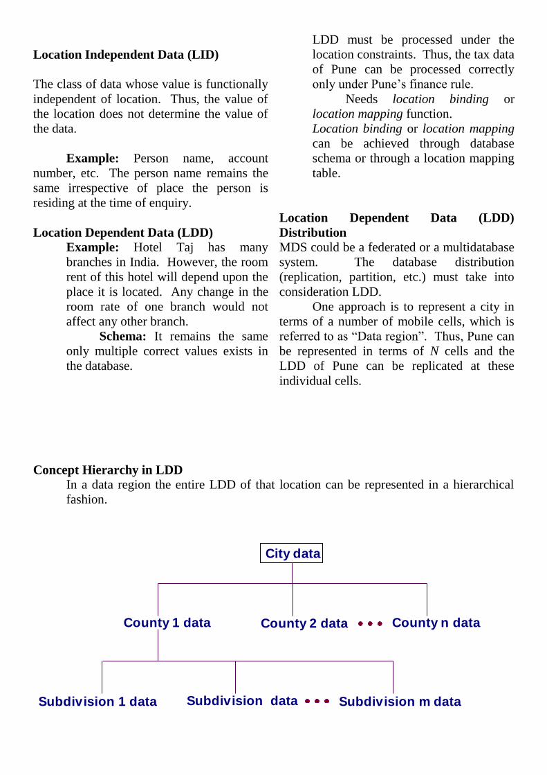
Location Independent Data (LID)
The class of data whose value is functionally
independent of location. Thus, the value of
the location does not determine the value of
the data.
Example: Person name, account
number, etc. The person name remains the
same irrespective of place the person is
residing at the time of enquiry.
Location Dependent Data (LDD)
Example: Hotel Taj has many
branches in India. However, the room
rent of this hotel will depend upon the
place it is located. Any change in the
room rate of one branch would not
affect any other branch.
Schema: It remains the same
only multiple correct values exists in
the database.
LDD must be processed under the
location constraints. Thus, the tax data
of Pune can be processed correctly
only under Pune’s finance rule.
Needs location binding or
location mapping function.
Location binding or location mapping
can be achieved through database
schema or through a location mapping
table.
Location Dependent Data (LDD)
Distribution
MDS could be a federated or a multidatabase
system. The database distribution
(replication, partition, etc.) must take into
consideration LDD.
One approach is to represent a city in
terms of a number of mobile cells, which is
referred to as ―Data region‖. Thus, Pune can
be represented in terms of N cells and the
LDD of Pune can be replicated at these
individual cells.
Concept Hierarchy in LDD
In a data region the entire LDD of that location can be represented in a hierarchical
fashion.
County 1 data County 2 data County n data
City data
Subdivision 1 data Subdivision data Subdivision m data
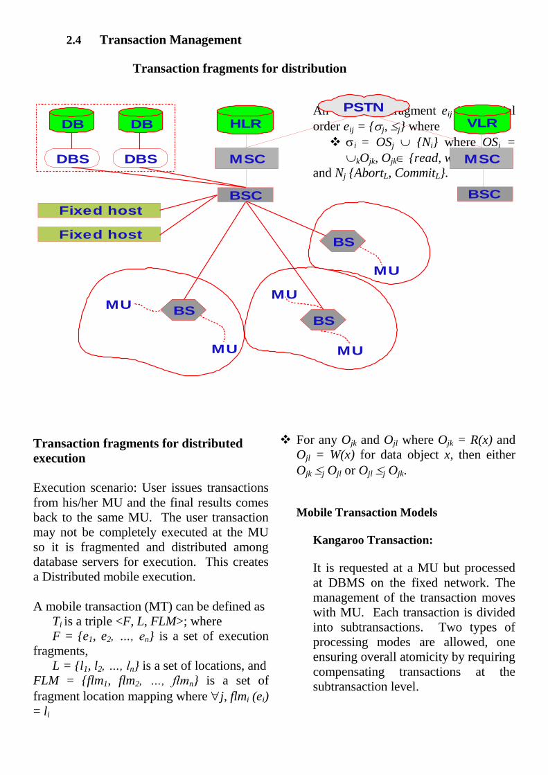
2.4 Transaction Management
Transaction fragments for distribution
Transaction fragments for distributed
execution
Execution scenario: User issues transactions
from his/her MU and the final results comes
back to the same MU. The user transaction
may not be completely executed at the MU
so it is fragmented and distributed among
database servers for execution. This creates
a Distributed mobile execution.
A mobile transaction (MT) can be defined as
Ti is a triple <F, L, FLM>; where
F = {e1, e2, …, en} is a set of execution
fragments,
L = {l1, l2, …, ln} is a set of locations, and
FLM = {flm1, flm2, …, flmn} is a set of
fragment location mapping where j, flmi (ei)
= li
An execution fragment eij is a partial
order eij = {j, j} where
i = OSj {Ni} where OSj =
kOjk, Ojk {read, write},
and Nj {AbortL, CommitL}.
For any Ojk and Ojl where Ojk = R(x) and
Ojl = W(x) for data object x, then either
Ojk j Ojl or Ojl j Ojk.
Mobile Transaction Models
Kangaroo Transaction:
It is requested at a MU but processed
at DBMS on the fixed network. The
management of the transaction moves
with MU. Each transaction is divided
into subtransactions. Two types of
processing modes are allowed, one
ensuring overall atomicity by requiring
compensating transactions at the
subtransaction level.
MSC MSC
DB DB HLR VLR
BSC BSC
DBS DBS
MUBS
MU
MU
BS
MU
BS
MU
Fixed host
Fixed host
PSTN
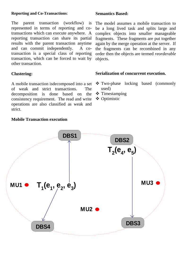
Reporting and Co-Transactions:
The parent transaction (workflow) is
represented in terms of reporting and co-
transactions which can execute anywhere. A
reporting transaction can share its partial
results with the parent transaction anytime
and can commit independently. A co-
transaction is a special class of reporting
transaction, which can be forced to wait by
other transaction.
Clustering:
A mobile transaction isdecomposed into a set
of weak and strict transactions. The
decomposition is done based on the
consistency requirement. The read and write
operations are also classified as weak and
strict.
Semantics Based:
The model assumes a mobile transaction to
be a long lived task and splits large and
complex objects into smaller manageable
fragments. These fragments are put together
again by the merge operation at the server. If
the fragments can be recombined in any
order then the objects are termed reorderable
objects.
Serialization of concurrent execution.
Two-phase locking based (commonly
used)
Timestamping
Optimistic
Mobile Transaction execution
DBS4
DBS1
DBS3
DBS2
T2(e
4, e
5)
MU2
MU1 T1(e
1, e
2, e
3) MU3
Reasons these methods may not work
satisfactorily
Wired and wireless message overhead.
Hard to efficiently support disconnected
operations.
Hard to manage locking and unlocking
operations.
Serialization of concurrent execution.
New schemes based on timeout,
multiversion, etc., may work. A scheme,
which uses minimum number of messages,
especially wireless messages is required.
Database update to maintain global
consistency.
Database update problem arises when
mobile units are also allowed to modify the
database. To maintain global consistency an
efficient database update scheme is
necessary.
Transaction commit.
In MDS a transaction may be fragmented and
may run at more than one nodes (MU and
DBSs). An efficient commit protocol is
necessary. 2-phase commit (2PC) or 3-phase
commit (3PC) is no good because of their
generous messaging requirement. A scheme
which uses very few messages, especially
wireless, is desirable.
One possible scheme is ―timeout‖ based
protocol.
Concept: MU and DBSs guarantee to
complete the execution of their fragments of
a mobile transaction within their predefined
timeouts. Thus, during processing no
communication is required. At the end of
timeout, each node commit their fragment
independently.
Protocol: TCOT-Transaction Commit
On Timeout
Requirements
Coordinator: Coordinates transaction
commit
Home MU: Mobile Transaction (MT)
originates here
Commit set: Nodes that process MT
(MU + DBSs)
Timeout: Time period for executing a
fragment
Protocol:
TCOT-Transaction Commit On
Timeout
MT arrives at Home MU.
MU extract its fragment, estimates
timeout, and send rest of MT to the
coordinator.
Coordinator further fragments the
MT and distributes them to
members of commit set.
MU processes and commits its
fragment and sends the updates to
the coordinator for DBS.
DBSs process their fragments and
inform the coordinator.
Coordinators commits or aborts
MT.
Transaction and database recovery
Complex for the following reasons
Some of the processing nodes are
mobile
Less resilient to physical use/abuse
Limited wireless channels
Limited power supply
Disconnected processing capability
Desirable recovery features
Independent recovery capability
Efficient logging and
checkpointing facility
Log duplication facility
Independent recovery capability
reduces communication overhead.
Thus, MUs can recover without any
help from DBS
Efficient logging and
checkpointing facility conserve
battery power
Log duplication facility improves
reliability of recovery scheme
Possible approaches
Partial recovery capability
Use of mobile agent technology
Possible MU logging approaches
Logging at the processing node
(e.g., MU)
Logging at a centralized location
(e.g., at a designated DBS)
Logging at the place of registration
(e.g., BS)
Saving log on Zip drive or floppies.
Mobile Agent Technology
A mobile agent is an independent software
module capable of
Migrating to any node on the network
Capable of spawning and eliminating
itself
Capable of recording its own history
A mobile agent can be used for the following
activities, which are essential for recovery.
Centralized and distributed logging
Log carrier. A Mobile unit may need to
carry its log with it for independent
recovery
Log processing for database recovery
Transaction commit or abort
Possible approaches
Agent broadcast on a dedicated wireless
channel
Pool of agents at every processing node
Agent migration to a required node.
Mobile E-commerce
What is E-commerce?
Mapping of business activity on the network.
The network may be mobile of ad-hoc in
which case the scope of business activities
significantly increases.
Why mobile E-commerce?
To make business activity free from spatial
constraints. This allows tremendous
flexibility to customers as well as to vendors.
Important gain: Making information
available at the right time, at the right
location, and in a right format.
Requirements for a mobile E-system
Security
Reliability
Efficient
Customer trust
Quality of service
These requirements are difficulty and
complex to achieve
Security
Conventional key approaches needs revision.
Reliability
Hard to provide mainly because of the
unreliability and limitations of resources.
Efficient
This capability can be easily improved
mainly because of the elimination of spatial
constraints.
Customer trust
A time consuming activity. Customer do not
easily trust electronic communication and
always wants to see a reliable backup
service.
Quality of service
Mobility and web provides ample scope for
improving the quality of service. An
integration of mobility, web, data
warehousing and workflow offers
tremendous growth potential and a very
controlled way of managing business
activities
2.5 Query Processing
MDS Query processing
Query types
Location dependent query
Location aware query
Location independent query
Location dependent query
A query whose result depends on the
geographical location of the origin of the
query.
Example
What is the distance of Pune railway
station from here?
The result of this query is correct only
for ―here‖.
Location dependent query
Situation: Person traveling in the car desires
to know his progress and continuously asks
the same question. However, every time the
answer is different but correct.
Requirements: Continuous monitoring of the
longitude and latitude of the origin of the
query. GPS can do this.
2.6 Location and Handoff Management
The handoff process is provided and the
topic of location management is introduced.
It first explains how these processes work
and then discusses their relevance to
transaction management in mobile database
systems. Quite a few location management
schemes have been proposed recently, but
none of them have been implemented in any
commercial system, so they are not
discussed. The working of existing handoff
and location mechanisms given in IS-41 is
explained.
Location Management
In cellular systems a mobile unit is free to
move around within the entire area of
coverage. Its movement is random and
therefore its geographical location is
unpredictable. This situation makes it
necessary to locate the mobile unit and
ecord its location to HLR and VLR when a
call has to be delivered to it.
Thus, the entire process of the mobility
management component of the cellular
system is responsible for two tasks:
(a) location management- that is,
identification of the current geographical
location or current point of attachment of a
mobile unit which is required by the MSC
(Mobile Switching Center) to route the call-
and
(b) handoff- that is, transferring (handing off)
the current (active) communication session to
the next base station, which seamlessly
resumes the session using its own set of
channels. The entire process of location
management is a kind of directory
management problem where locations are
current locations are maintained
continuously.

One of the main objectives of efficient
location management schemes is to minimize
the communication overhead due to database
updates (mainly HLR) [6,9, 151.
The other related issue is the distribution of
HLR to shorten the access path, which is
similar to data distribution problem in
distributed database systems. Motivated by
these issues, recently a number of innovative
location management schemes have appeared
in the research world [ 141. The current point
of attachment or location of a subscriber
(mobile unit) is expressed in terms of the cell
or the base station to which it is presently
connected. The mobile units (called and
calling subscribers) can continue to talk and
move around in their respective cells; but as
soon as both or any one of the units moves to
a different cell, the location management
procedure is invoked to identify the new
location.
The unrestricted mobility of mobile units
presents a complex dynamic environment,
and the location management component
must be able to identify the correct location
of a unit without any noticeable delay. The
location management performs three
fundamental tasks: (a) location update, (b)
location lookup, and (c) paging. In location
update, which is initiated by the mobile unit,
the current location of the unit is recorded in
HLR and VLR databases. Location lookup is
basically a database search to obtain the
current location of the mobile unit and
through paging the system informs the caller
the location of the called unit in terms of its
current base station.
These two tasks are initiated by the MSC.
The cost of update and paging increases as
cell size decreases, which becomes quite
significant for finer granularity cells such as
micro- or picocell clusters. The presence of
frequent cell crossing, which is a common
scenario in highly commuting zones, further
adds to the cost. The system creates location
areas and paging areas to minimize the cost.
A number of neighboring cells are grouped
together to form a location area, and the
paging area is constructed in a similar way.
In some situations, remote cells may be
included in these areas. It is useful to keep
the same set of cells for creating location and
paging areas, and in most commercial
systems they are usually identical. This
arrangement reduces location update
frequency because location updates are not
necessary when a mobile unit moves in the
cells of a location area. A large number of
schemes to achieve low cost and infrequent
update have been proposed, and new
schemes continue to emerge as cellular
technology advances.
A mobile unit can freely move around in
(a) active mode,
(b) doze mode, or
(c) power down mode.
In active mode the mobile actively
communicates with other subscriber, and it
may continue to move within the cell or may
encounter a handoff which may interrupt the
communication. It is the task of the location
manager to find the new location and resume
the communication. In doze mode a mobile
unit does not actively communicate with
other subscribers but continues to listen to
the base station and monitors the signal
levels around it, and in power down mode
the unit is not functional at all. When it
moves to a different cell in doze or power
down modes, then it is neither possible nor
necessary for the location manager to find
the location. The location management
module uses a two-tier scheme for location-
related tasks.
The first tier provides a quick location
lookup, and the second tier 4earch is initiated
only when the first tier search fails.
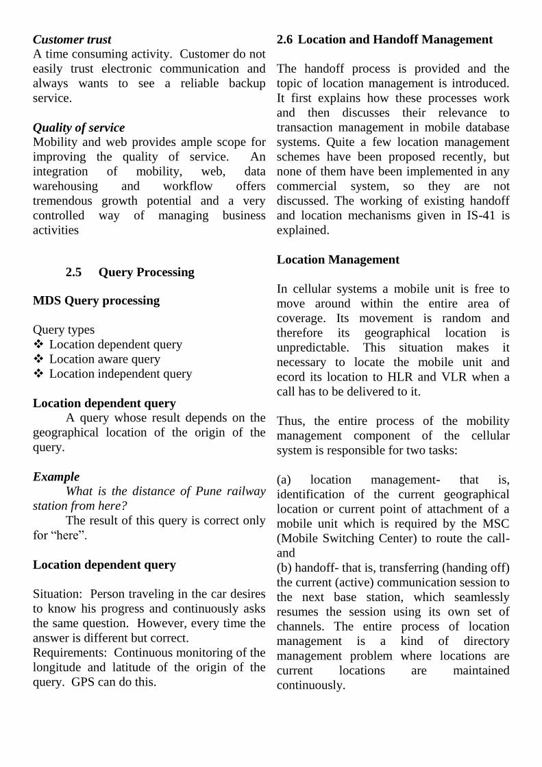
Handoff Management
This section discuses how a handoff is
managed to provide continuous connectivity.
Figure illustratesthe presence of an overlap
region between Cell 1 and Cell 2. A mobile
unit may spends some time in this overlap
area and the value of this duration depends
upon the movement speed of the mobile unit.
The duration a mobile unit stays in this area
is called the degradation interval . The
objective is to complete a handoff process
while the mobile unit is still in the overlap
area. This implies that the handoff must not
take more than the degradation interval to
complete he process. If for some reason the
process fails to complete in this area or
within degradation interval, then the call is
dropped.
Fig. Cell overlap region.
A handoff may happen within or outside a
registration area. If it happens within a
registration area, then it is referred to as
intra-system handoff where the same MSC
manages the entire process. An intersystem
handoff occurs between two separate
registration areas where two MSCs are
involved in handoff processing. In each of
these cases the handoff processing is
completed in three steps:
Handoff detection: The system detects
when a handoff process needs to be
initiated.
Assignment of channels: During handoff
processing the system
identifies new channels to be assigned
for continuous connectivity.
Transfer of radio link: The identified
channels are allocated to the mobile
unit.
Handoff Detection
Handoff processing is expensive, so the
detection process must correctly detect a
genuine and False Handoff which also
occurs because of signal fading. There are
three approaches for detecting handoff
effectively and accurately.
A brief description of these approaches,
which are applied on GSM system but also

used in PCS, is presented here and further
details can be found in Ref. [lo]. They are
called:
Mobile-Assisted Handoff (MAHO)
Mobile-Controlled Handoff (MCHO)
Network-Controlled Handoff (NCHO)
Mobile-Assisted Handoff (MAHO):
This scheme is implemented in second-
generation systems where TDMA technology
is used. In this approach, every mobile unit
continuously measures the signal strength
from surrounding base stations and notifies
the strength data to the serving base station.
The strength of these signals are analyzed,
and a handoff is initiated when the strength
of a neighboring base station exceeds the
strength of the serving base station. The
handoff decision is made jointly by base
station and Mobile Switching Center (MSC)
or base station controller (BSC). In case the
Mobile Unit (MU) moves to a different
registration area, an intersystem handoff is
initiated.
Mobile-Controlled Handoff (MCHO):
In this scheme the Mobile Unit (MU) is
responsible for detecting a handoff. The MU
continuously monitors the signal strength
from neighboring base stations and identifies
if a handoff is necessary. If it finds the
situation for more than one handoff, then it
selects the base station with strongest signal
for initiating a handoff.
Network-Controlled Handoff (NCHO):
In this scheme, Mobile Unit (MU) does not
play any role in handoff detection. The BS
monitors the signal strength used by MUs
and if it falls below a threshold value, the BS
initiates a handoff. In this scheme also BS
and MSC are involved in handoff detection.
In fact the MSC instructs BSs to monitor the
signal strength occasionally, and in
collaboration with BSs the handoff situation
is detected. The MAHO scheme shares some
detection steps of NCHO. Necessary
resources for setting up a call or to process a
handoff request may not always be available.
For example, during a handoff the
destination BS may not have any free
channel, the MU is highly mobile and has
requested too many handoffs, the system is
taking too long to process a handoff, the link
transfer suffered some problem, and so on. In
any of these cases the handoff is terminated
and the mobile unit loses the connection.
Radio Link Transfer
The last phase of handoff is the transfer of
the radio link. The hierarchical structure of
cellular system (PCS and GSM) presents the
following five-link transfer cases for which
handoff has to be processed.
Intracell handoff Link or channel
transfer occurs for only one BS. In this
handoff a MU only switches channel.
Figure 3.10 illustrates the scenario.
Intercell or Inter-BS handoff The link
transfer takes place between two BSs
which are connected to the same BSC.
Figure 3.1 1 illustrates the scenario.
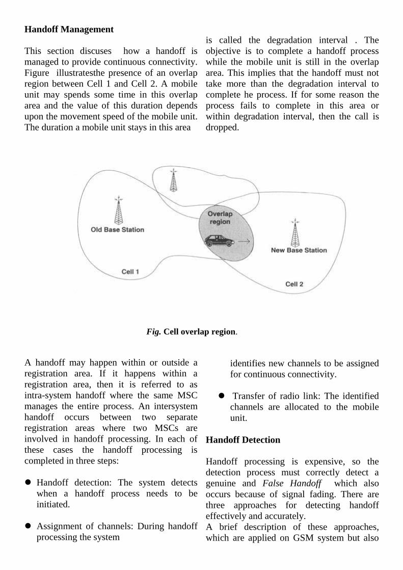
Inter-BSC handoff: The link transfer
takes place between two BSs which are
connected to two different BSCs and the
BSC is connected to one MSC. Figure
3.12 illustrates the scenario.
Intersystem or Inter-MSC handoff The
link transfer takes place between two BSs
which are connected to two different
BSCs. These two BSCs are connected to
two different MSCs. Figure 3.13
illustrates the situation.
As discussed in Ref. [ 101, typical call
holding time is around 60 seconds. Some
real-life data indicates that there could be
around 0.5 inter-BS handoff, 0.1 inter-BSC

Fig. 3.10 Channel transfer in intracell handoff.
Fig. 3.11 Channel transfer between two BSs with one BSC.
handoff, and 0.05 inter-MSC handoff. The
data also indicate that the failure rate of
inter-MSC handoff is about five times more
than inter-BS handoff. It is quite obvious that
efficient processing of handoff is quite
important for minimizing the call waiting
time. There are two ways to achieve link
transfer. One way is referred to as Hard
Handofland the other as Soft Handoff.
Fig. 3.72 Channel transfer between two BSs connected to two BSCs.
Hard Handoff:
In this handoff process the user experiences a
brief silence or discontinuity in
communication which occurs because at any
time the MU is attached to only one BS and
when the link is transfer the connection is
broken temporarily resulting in a silence. The
steps of the handoff for MCHO link transfer
is described below.
1. MS sends a ―link suspend‖ message to the
old BS which temporarily suspends the
conversation (occurrence of silence).
2. The MS sends a ―handoff request
message― to the network through the new
BS. The new BS then sends a ―handoff
acknowledgement― message and marks the
slot busy. This message indicates the
initiation of the handoff process.
3. This acknowledgment message indicates
to MU that the handoff process has started,
and so MU returns to the old channel it was
using and resumes voice communication
while network process the handoff.
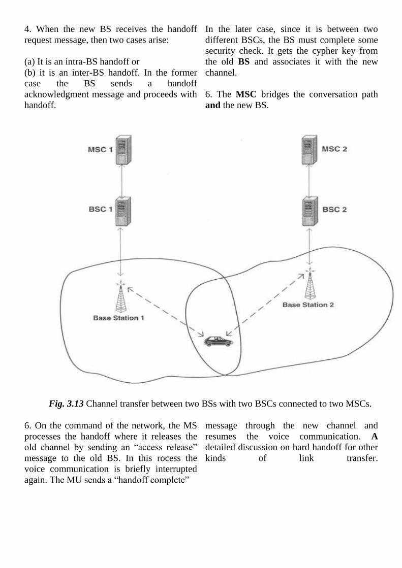
4. When the new BS receives the handoff
request message, then two cases arise:
(a) It is an intra-BS handoff or
(b) it is an inter-BS handoff. In the former
case the BS sends a handoff
acknowledgment message and proceeds with
handoff.
In the later case, since it is between two
different BSCs, the BS must complete some
security check. It gets the cypher key from
the old BS and associates it with the new
channel.
6. The MSC bridges the conversation path
and the new BS.
Fig. 3.13 Channel transfer between two BSs with two BSCs connected to two MSCs.
6. On the command of the network, the MS
processes the handoff where it releases the
old channel by sending an ―access release‖
message to the old BS. In this rocess the
voice communication is briefly interrupted
again. The MU sends a ―handoff complete‖
message through the new channel and
resumes the voice communication. A
detailed discussion on hard handoff for other
kinds of link transfer.

2.6 Wireless Information Broadcast
The data dissemination discipline gives an
illusion that the space is an infinite size
persistent data storage from where a user can
download desired information. For example,
information about airline schedule, weather,
stock quotes, etc., can be downloaded from
the broadcast. Initially, data dissemination
system appeared as an information
dissemination tool similar to radio broadcast,
but with advances in wireless and satellite
communication, it is becoming an
information management system as well.
This chapter discusses data dissemination
technology and development of schemes
such as indexing, push and pull, data staging,
surrogates, and so on, for incorporating
transactional facility. The discussion in this
chapter is based mostly on research reports
because a truly data broadcast system has not
been developed and deployed for commercial
use. It also discusses in detail the architecture
and working of a reference data
dissemination and processing system called
DAYS (DAta in your Space).
The discipline of data dissemination
through wireless channel, that is, data
broadcast, has added another dimension in
the area of mobile computing. The mobile
database systems, discussed in preceding
chapters, provided terminal and personal
mobility in information management, and the
wireless data dissemination took mobile
systems one step further and allowed the user
to tune and access and process desired
information from anywhere in the world.
Accessing data from wireless channel is a
very useful facility because it allows users
to get desired data through many
computationally enabled devices such as
cellular phones, PDAs, other new devices.
Manufacturers continue to develop
increasingly powerful mobile devices while
decreasing their size and cost. If it is
assumed that there is an abundance of
wireless channels, then servers can continue
to push all data users can ever need on these
channels and users can pull whatever they
require. This is an ideal scenario. In reality,
wireless channels are always less than the
number required to satisfy users’ demands.
Thus, the task of data dissemination
technology is to develop ways for satisfying
users’ data demand with limited wireless
resources.
Data broadcast is predominately user-
independent. The users are passive in that
they can only read what is contained in a
broadcast. While this model fits well into
some types of data dissemination (such as
local traffic information), it is not general
enough for many different types of
applications. Some examples can help to
identify its usefulness and limitations.

Data Broadcast Mode
The mode of data transfer is essentially
asymmetric, that is, the capacity of the
transfer of data from the server to the mobile
client downstream communication is
significantly larger than the client or mobile
user to the server upstream communication.
The effectiveness of a data
dissemination system is evaluated by its
ability to provide a user his required data
ubiquitously. There are two basic modes of
data dissemination. These modes are
motivated mainly by limited power
consideration. The lifetime of a battery is
expected to increase only 20% over the next
10 years 1221. A typical AA cell is rated to
give 800 mA/hour at I .2 V (0.96 Whour).
The constant power dissipation in a CD-
ROM (for disk spinning itself) is about 1 W,
and the power dissipation for display is
around 2.5 W. The available power source is
likely to last for 2.7 hours and to preserve
battery power; these activities must be
disabled whenever possible. The Hobbit chip
from AT&T allows the operation in two
modes:
(a) active mode – the full operational
mode where CPU and all other components
are in running state and
(b) doze mode - the power conserving
mode where the CPU is inactive.
The power consumption in the active
mode is 250 mW, and the power
consumption in doze mode is 50 pW. The
ratio of power consumption in the active
mode to doze mode is 5000.
When the mobile unit (palmtop) is
listening to the channel, the CPU must be in
the active mode for examining data buckets
in the broadcast. The CPU consumes more
power than some receivers, especially if it
has to be active to examine all incoming
buckets. Therefore, it will be beneficial if the
CPU can be switched to the doze mode
whenever it is not being used and switched
back to active mode when the data of interest
arrives on the broadcast channel. This facility
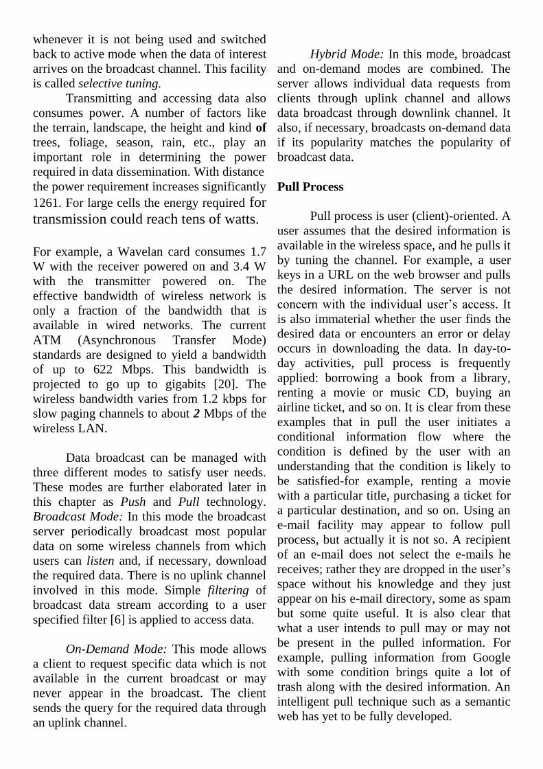
is called selective tuning.
Transmitting and accessing data also
consumes power. A number of factors like
the terrain, landscape, the height and kind of
trees, foliage, season, rain, etc., play an
important role in determining the power
required in data dissemination. With distance
the power requirement increases significantly
1261. For large cells the energy required for
transmission could reach tens of watts.
For example, a Wavelan card consumes 1.7
W with the receiver powered on and 3.4 W
with the transmitter powered on. The
effective bandwidth of wireless network is
only a fraction of the bandwidth that is
available in wired networks. The current
ATM (Asynchronous Transfer Mode)
standards are designed to yield a bandwidth
of up to 622 Mbps. This bandwidth is
projected to go up to gigabits [20]. The
wireless bandwidth varies from 1.2 kbps for
slow paging channels to about 2 Mbps of the
wireless LAN.
Data broadcast can be managed with
three different modes to satisfy user needs.
These modes are further elaborated later in
this chapter as Push and Pull technology.
Broadcast Mode: In this mode the broadcast
server periodically broadcast most popular
data on some wireless channels from which
users can listen and, if necessary, download
the required data. There is no uplink channel
involved in this mode. Simple filtering of
broadcast data stream according to a user
specified filter [6] is applied to access data.
On-Demand Mode: This mode allows
a client to request specific data which is not
available in the current broadcast or may
never appear in the broadcast. The client
sends the query for the required data through
an uplink channel.
Hybrid Mode: In this mode, broadcast
and on-demand modes are combined. The
server allows individual data requests from
clients through uplink channel and allows
data broadcast through downlink channel. It
also, if necessary, broadcasts on-demand data
if its popularity matches the popularity of
broadcast data.
Pull Process
Pull process is user (client)-oriented. A
user assumes that the desired information is
available in the wireless space, and he pulls it
by tuning the channel. For example, a user
keys in a URL on the web browser and pulls
the desired information. The server is not
concern with the individual user’s access. It
is also immaterial whether the user finds the
desired data or encounters an error or delay
occurs in downloading the data. In day-to-
day activities, pull process is frequently
applied: borrowing a book from a library,
renting a movie or music CD, buying an
airline ticket, and so on. It is clear from these
examples that in pull the user initiates a
conditional information flow where the
condition is defined by the user with an
understanding that the condition is likely to
be satisfied-for example, renting a movie
with a particular title, purchasing a ticket for
a particular destination, and so on. Using an
e-mail facility may appear to follow pull
process, but actually it is not so. A recipient
of an e-mail does not select the e-mails he
receives; rather they are dropped in the user’s
space without his knowledge and they just
appear on his e-mail directory, some as spam
but some quite useful. It is also clear that
what a user intends to pull may or may not
be present in the pulled information. For
example, pulling information from Google
with some condition brings quite a lot of
trash along with the desired information. An
intelligent pull technique such as a semantic
web has yet to be fully developed.

Advantages of Pull: It is user-friendly
and provides interactive capability to users
for accessing the information through query.
The user does not need to search in the
wireless information space by tuning several
channels.
Disadvantages of Pull: In wireless
data dissemination platform, the pull
approach is resource-intensive. A user
requires a separate channel to send the
request as a SQL query or in some other
form to the server for the desired
information. The server, after receiving the
request, composes the result and must send it
to the user on a back channel (downstream)
known to the user. Thus every pull needs two
channels for completing the process
successfully. If there are a large number of
users and they need identical information,
then each user will occupy two channels with
identical data on all back channels. This
cannot be easily afforded because of narrow
bandwidth available for wireless
communication. It appears from these
limitations that pull is good for special cases
of data retrieval.
Push Process
In the push process, the server
broadcasts data (pushes data) on one or
multiple channels. For example, it can push
weather information on one channel, traffic
information on another channel, and so on.
Clients, depending upon their data
requirements, tune the appropriate channel.
In a push system a client cannot send a
specific query to the server, nor is the server
broadcast client-specific. The push
technology was introduced somewhere
around April 1996 by an internet company
called PointCast Inc. The company started
push scheme by broadcasting selected news
and stock quotes to a client’s machine at
predefined intervals [ 141. The client tuned
and downloaded information at these
intervals. This was the beginning of an
effective way of reaching a larger number of
customers. Developers and researchers found
the push scheme quite useful; since then, it
was deployed on the internet in many ways
such as webcasting or netcasting. Sometimes
it is also called PointCusting to honor the
company which invented it.
The main objective of push technology
was to handle the problem of information
overload due to low bandwidth which
restricted users to receive multimedia
contents. The push scheme provided an
effective means to pre-deliver much larger
packages of audio, large graphics, or short
video clips. The push technology can be
augmented with a number of mechanisms to
increase its scope and effectiveness. For
example, message indexing can be
implemented to speed up broadcast search,
caching can be used to reduce data miss, data
staging can be augmented to enhance data
availability, personalization of channel
contents can help to satisfy specific user, the
smart-pull approach can assist users to get
specific information, and so on. These topics
are discussed in detail in subsequent sections.
Push Application
The push technology has been
deployed for sometime in many real-world
activities such as in the financial world to
broadcast stock quotes, mutual funds costs,
real state costs and inflation status, news,
cable television broadcast, etc. Nearly all
software manufacturers use push to broadcast
application and system updates and fixes to
clients’ machines. Many companies use this
technology for advertisement. In fact, most
of the commercials on broadcast media such
as television, radio, etc., are pushbased.
Companies are at a great advantage for
making use of the push technology which
allows them to make instant changes in the
broadcast or refresh it entirely based on
users’ feedback to increase their effect on
consumers. It is not now necessary for them
to rely on a human operator to search a site
for outdated material. The push technology
applies to entertainment and leisure equally
effectively.
The push technology is especially
useful in the intranet market. Companies can
push on their intranet corporate information
to employees using a predefined schedule. It
guarantees identical message delivery, which
is highly desirable, to all employees.
Accessing Information from Broadcast
Clients can access and download
required information in a variety of ways,
which depends upon how the broadcast was
composed and pushed on the channel by the
server. In a channel the push is strictly
sequential. Data are dropped in the channel,
one at a time. This can be viewed as a string
of different categories of data. For example,
if the broadcast is composed of weather
information, traffic information, and dining
places information, then they will appear on
the broadcast sequentially in the order they
were dropped in the channel. The client will
receive the broadcast in the order sent by the
server.
At the client’s end the Fimplest way to
access the information is sequentially. In
most cases this access is time consuming. A
client, if interested only i n dining
information, has to tune and wait until the
dining information appears in the broadcast.
In a wireless platform, any waiting-let alone
waiting for information to appear-is quite
resource-expensive, especially from a
bandwidth viewpoint. An ideal scheme is to
tune when the desired information appears
(e.g., selective tuning) and download the
data; that is, the waiting time for information
access is zero. It is impossible to implement
the ideal scheme, but the access time can be
significantly minimized through efficient
indexing and carefully composing the
broadcast. Such arrangements actually create
a notion of smart-pull where client can pull
exactly the information he wanted with
minimum redundancy. However, even
though push applications are not really push,
there is a difference in them. The difference
is the automation of the process both for the
server and the client. There are a couple of
true push technology applications-for
example, products like AirMedia Live and
Wayfarer (INCISA).
Push Advantages and Disadvantages
Push technology has been a favorite
choice of data dissemination because of its
several advantages. It has, however, several
disadvantages which makes it unsuitable,
especially for providing transactional facility.
Advantages
In a large information flow it minimizes
the burden of acquiring data. The server
can keep the information up to date by
broadcasting it on a regular interval;
consequently, the user always has the
latest information. A user is aware of the
broadcast channel carrying the
information and the exact location of the
data in the broadcast. This setup
significantly reduces the search time.
Sends the user the time-critical data for
immediate attention.
Helps organizations (academic, business,
or commercial) to identify, focus, and
reach those users with precision who are
more likely to benefit from their products
or services.
Automatically delivers directly to clients’
machines software upgrades and fixes
faster and, at the same time, reduce or
eliminate the shipping cost. This facility
requires a mechanism to check clients’
machines for software and configuration
and then modify these configurations.
Uses incremental updates where only new
and changed information has to be sent to
the computer which significantly reduces
access and download time.
Helps server to reserve more processing
time for data production by avoiding to
handle numerous client requests
individually.
Shortens response time.
Easily protects user privacy because push
applications run mostly at the client
machine and client’s profile and the log
information about the client’s behavior
are stored on the client’s computer.
Enables intelligent information filtering
based on personalized user profiles
describing required information needs.
Satisfies a large client base using few
resources.
Disadvantages
The push technology, while it is useful
in a number of situations and does conserve
resources and energy, has a number of
limitations and disadvantages [ 141. Some
important ones are given below.
Push applications are complex, and the
development cost (time and resource) are
generally high compared to creating static
pages. Static pages can be viewed by any
browser on any operating system, but the
push system requires specific tools and
applications.
It requires more powerful hardware and
specialized software to provide push
service.
Identifying the location of the desired
information in the broadcast and
downloading the multimedia contents
require a huge amount of disk storage.
It suffers a number of unresolved
bandwidth problems. Problems arise due
to the enormous bandwidth that push
technologies can require when feeding
data to thousands of end users. Caching
proxy servers, for example, as well as
multicast solutions, will likely solve many
of the bandwidth problems of push and
allow it to scale. Some providers allow
users to choose when the information is
downloaded, so users can schedule it for
times that they will be away from their
computer.
The push scheme is still not that useful
for individual users; however, the
emergence of music P2P systems has
made it quite popular. Its usefulness is
still confined to organizations that have a
good customer base.
In multiple push a user can get frequent
interruption. For example, during a song
broadcast, some urgent message can
appear to notify user of some serious
event. Although users get the information,
they may have to live with constant
interruption. Such interruptions cannot be
preplanned because they may occur
randomly.
Push system software may suffer with
incompatibility problem. Many vendors-
Air Media, Alpha Microsystems,
Berkeley Systems, IntraExpress,
Marimba, Pointcast, to name a few,
develop application software with
minimum portability and scalability.
Competition to dominate the information
space in this technology is growing fast
and vendors are unable to develop
software compatible to all systems. The

push technology is not good for the
typical knowledge worker who mines
information from a variety of sources and
then draws conclusions by digesting that
information [ 141.
Creating and maintaining user profiles is
time-consuming. This becomes more
expensive with number of users. One of
the main reasons is that users’
information needs are constant to some
degree only.
There is no reliable solution to achieve
secured broadcast. Security safeguards are
highly needed.
Standards are currently lacking in this
area (competing de facto industry
standards are pushed by companies) .
Market for Push Technology
Microsoft Corp. and Netscape
Communications Corp. are the two leading
competitors
in the push technology. Microsoft is pushing
the Extensible Markup Language (XML)-
based Channel Definition Format (CDF) for
defining push updates. Netscape is using the
Meta-Content Format (MCF), which was
invented by Apple Computer. For example,
Marimba Inc. has begun cooperation with
Netscape. Microsoft and Netscape each have
created their own push clients for use in
conjunction with their latest browsers. The
push market can be divided into four basic
categories :
Application Distributor: The products
of this category such as Marimba’s
Castanet provide automatic delivery of
application software to end users.
Content aggregator: The products of this
category-for example, PointCast Business
Network-gather and format the contents
in a consistent wrapper and push it to
users’ workstations.
Platform provider: The products of this
category-for example, BackWeb-are
similar to content aggregators, except
they are actually infrastructure to deploy
content delivery systems.
Real-time data transfer: The products of
this category-for example, TIBCO and
Wayfarer (1NCISA)-offer the advantage
of multicasting. It is expensive to
implement, but they guarantee timely
delivery of information possible.
Push information delivery models can be
categorized at least into three main
categories :
Push Server Model: It is the most
common Push Server Model which
provides a client, a server, and
development tools. A proprietary client is
supplied, and the applications may use a
proprietary protocol. Both users and
content providers have control over the
content. Some examples of this model are
BackWeb and Marimba’s Castanet.
Web Server Extension Model: In this
model, the push vendor directs feedback
and demographic information to an
external server, so that information can be
retained by the push vendor. No
proprietary client is required. These run
within the user’s installed browser, such
as Pointcast or the server delivers content
using e-mail, such as ChannelManager
and InfoBeat.
Client Agent Model: This model uses a
―client agent‖ to retrieve the information
from the web. Each agent is designed to
provide different search results and allows
us to establish an anonymous relationship
between the vendor and the subscriber.
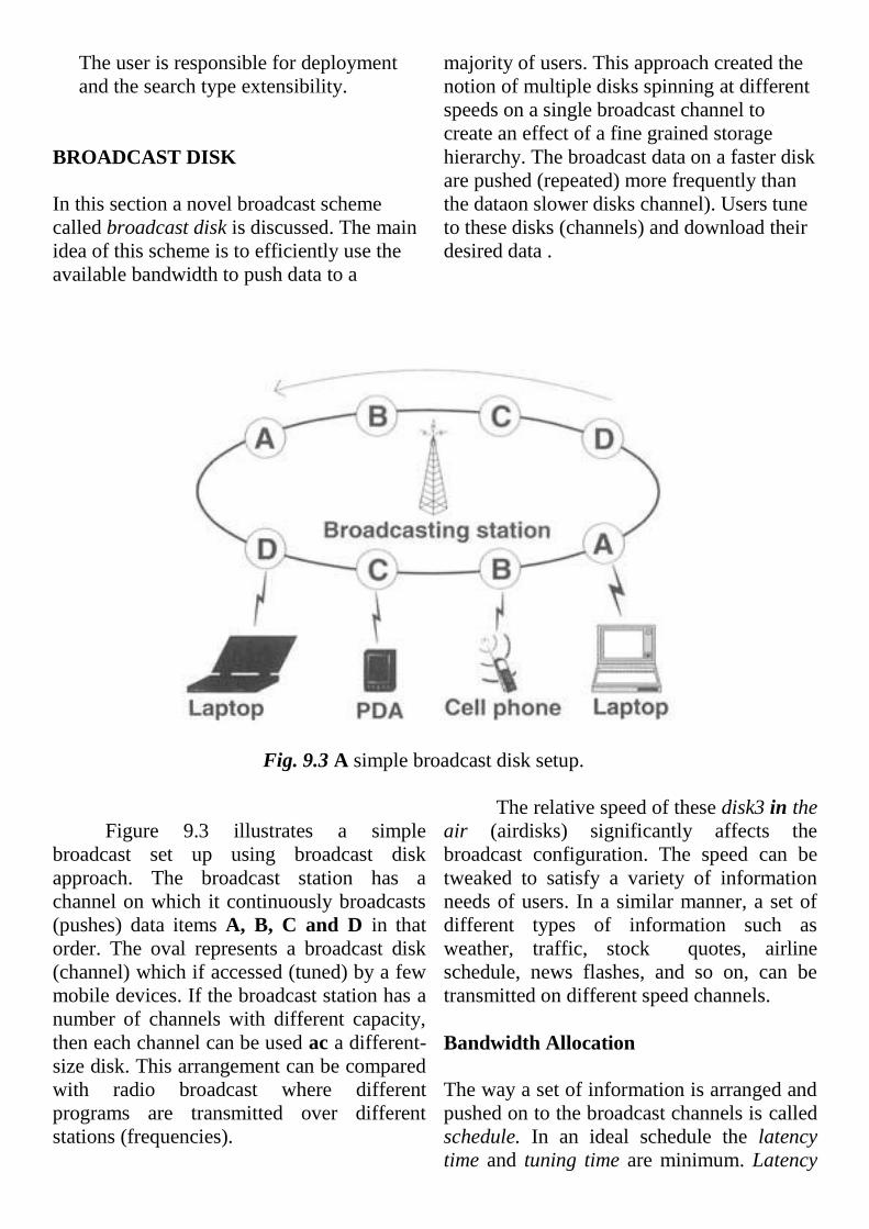
The user is responsible for deployment
and the search type extensibility.
BROADCAST DISK
In this section a novel broadcast scheme
called broadcast disk is discussed. The main
idea of this scheme is to efficiently use the
available bandwidth to push data to a
majority of users. This approach created the
notion of multiple disks spinning at different
speeds on a single broadcast channel to
create an effect of a fine grained storage
hierarchy. The broadcast data on a faster disk
are pushed (repeated) more frequently than
the dataon slower disks channel). Users tune
to these disks (channels) and download their
desired data .
Fig. 9.3 A simple broadcast disk setup.
Figure 9.3 illustrates a simple
broadcast set up using broadcast disk
approach. The broadcast station has a
channel on which it continuously broadcasts
(pushes) data items A, B, C and D in that
order. The oval represents a broadcast disk
(channel) which if accessed (tuned) by a few
mobile devices. If the broadcast station has a
number of channels with different capacity,
then each channel can be used ac a different-
size disk. This arrangement can be compared
with radio broadcast where different
programs are transmitted over different
stations (frequencies).
The relative speed of these disk3 in the
air (airdisks) significantly affects the
broadcast configuration. The speed can be
tweaked to satisfy a variety of information
needs of users. In a similar manner, a set of
different types of information such as
weather, traffic, stock quotes, airline
schedule, news flashes, and so on, can be
transmitted on different speed channels.
Bandwidth Allocation
The way a set of information is arranged and
pushed on to the broadcast channels is called
schedule. In an ideal schedule the latency
time and tuning time are minimum. Latency
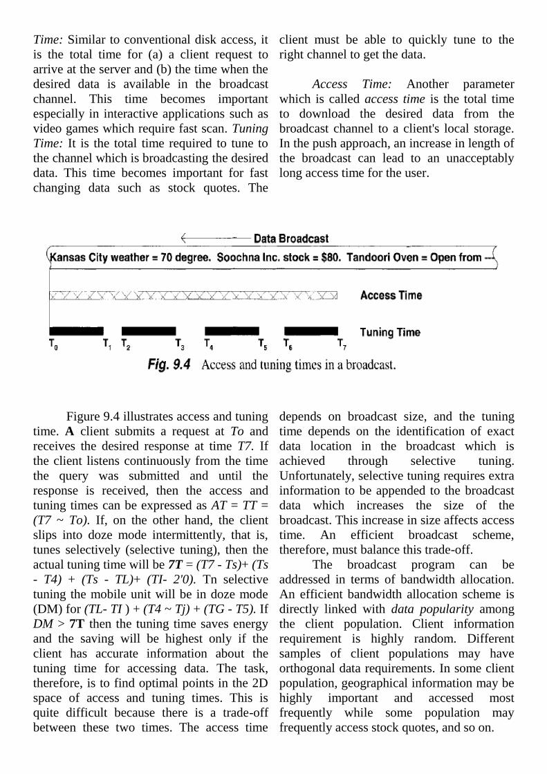
Time: Similar to conventional disk access, it
is the total time for (a) a client request to
arrive at the server and (b) the time when the
desired data is available in the broadcast
channel. This time becomes important
especially in interactive applications such as
video games which require fast scan. Tuning
Time: It is the total time required to tune to
the channel which is broadcasting the desired
data. This time becomes important for fast
changing data such as stock quotes. The
client must be able to quickly tune to the
right channel to get the data.
Access Time: Another parameter
which is called access time is the total time
to download the desired data from the
broadcast channel to a client's local storage.
In the push approach, an increase in length of
the broadcast can lead to an unacceptably
long access time for the user.
Figure 9.4 illustrates access and tuning
time. A client submits a request at To and
receives the desired response at time T7. If
the client listens continuously from the time
the query was submitted and until the
response is received, then the access and
tuning times can be expressed as AT = TT =
(T7 ~ To). If, on the other hand, the client
slips into doze mode intermittently, that is,
tunes selectively (selective tuning), then the
actual tuning time will be 7T = (T7 - Ts)+ (Ts
- T4) + (Ts - TL)+ (TI- 2'0). Tn selective
tuning the mobile unit will be in doze mode
(DM) for (TL- TI ) + (T4 ~ Tj) + (TG - T5). If
DM > 7T then the tuning time saves energy
and the saving will be highest only if the
client has accurate information about the
tuning time for accessing data. The task,
therefore, is to find optimal points in the 2D
space of access and tuning times. This is
quite difficult because there is a trade-off
between these two times. The access time
depends on broadcast size, and the tuning
time depends on the identification of exact
data location in the broadcast which is
achieved through selective tuning.
Unfortunately, selective tuning requires extra
information to be appended to the broadcast
data which increases the size of the
broadcast. This increase in size affects access
time. An efficient broadcast scheme,
therefore, must balance this trade-off.
The broadcast program can be
addressed in terms of bandwidth allocation.
An efficient bandwidth allocation scheme is
directly linked with data popularity among
the client population. Client information
requirement is highly random. Different
samples of client populations may have
orthogonal data requirements. In some client
population, geographical information may be
highly important and accessed most
frequently while some population may
frequently access stock quotes, and so on.
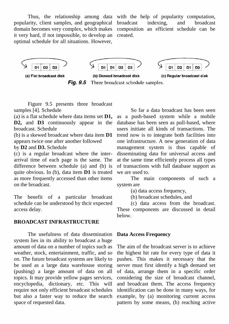
Thus, the relationship among data
popularity, client samples, and geographical
domain becomes very complex, which makes
it very hard, if not impossible, to develop an
optimal schedule for all situations. However,
with the help of popularity computation,
broadcast indexing, and broadcast
composition an efficient schedule can be
created.
Figure 9.5 presents three broadcast
samples [4]. Schedule
(a) is a flat schedule where data items set D1,
D2, and D3 continuously appear in the
broadcast. Schedule
(b) is a skewed broadcast where data item D1
appears twice one after another followed
by D2 and D3. Schedule
(c) is a regular broadcast where the inter-
arrival time of each page is the same. The
difference between schedule (a) and (b) is
quite obvious. In (b), data item D1 is treated
as more frequently accessed than other items
on the broadcast.
The benefit of a particular broadcast
schedule can be understood by thcir expected
access delay.
BROADCAST INFRASTRUCTURE
The usefulness of data dissemination
system lies in its ability to broadcast a huge
amount of data on a number of topics such as
weather, stock, entertainment, traffic, and so
on. The future broadcast systems are likely to
be used as a large data warehouse storing
(pushing) a large amount of data on all
topics. It may provide yellow pages services,
encyclopedia, dictionary, etc. This will
require not only efficient broadcast schedules
but also a faster way to reduce the search
space of requested data.
So far a data broadcast has been seen
as a push-based system while a mobile
database has been seen as pull-based, where
users initiate all kinds of transactions. The
trend now is to integrate both facilities into
one infrastructure. A new generation of data
management system is thus capable of
disseminating data for universal access and
at the same time efficiently process all types
of transactions with full database support as
we are used to.
The main components of such a
system are
(a) data access frequency,
(b) broadcast schedules, and
(c) data access from the broadcast.
These components are discussed in detail
below.
Data Access Frequency
The aim of the broadcast server is to achieve
the highest hit rate for every type of data it
pushes. This makes it necessary that the
server must first identify a high demand set
of data, arrange them in a specific order
considering the size of broadcast channel,
and broadcast them. The access frequency
identification can be done in many ways, for
example, by (a) monitoring current access
pattern by some means, (b) reaching active
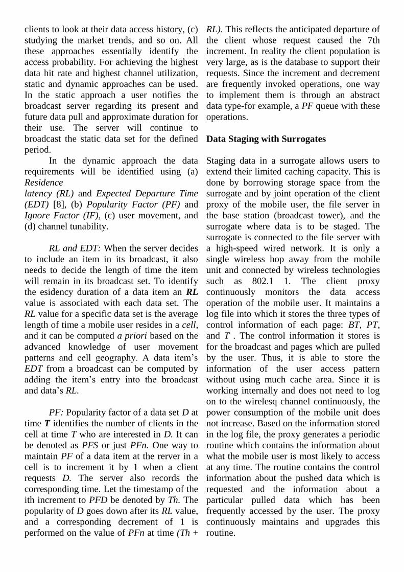
clients to look at their data access history, (c)
studying the market trends, and so on. All
these approaches essentially identify the
access probability. For achieving the highest
data hit rate and highest channel utilization,
static and dynamic approaches can be used.
In the static approach a user notifies the
broadcast server regarding its present and
future data pull and approximate duration for
their use. The server will continue to
broadcast the static data set for the defined
period.
In the dynamic approach the data
requirements will be identified using (a)
Residence
latency (RL) and Expected Departure Time
(EDT) [8], (b) Popularity Factor (PF) and
Ignore Factor (IF), (c) user movement, and
(d) channel tunability.
RL and EDT: When the server decides
to include an item in its broadcast, it also
needs to decide the length of time the item
will remain in its broadcast set. To identify
the esidency duration of a data item an RL
value is associated with each data set. The
RL value for a specific data set is the average
length of time a mobile user resides in a cell,
and it can be computed a priori based on the
advanced knowledge of user movement
patterns and cell geography. A data item’s
EDT from a broadcast can be computed by
adding the item’s entry into the broadcast
and data’s RL.
PF: Popularity factor of a data set D at
time T identifies the number of clients in the
cell at time T who are interested in D. It can
be denoted as PFS or just PFn. One way to
maintain PF of a data item at the rerver in a
cell is to increment it by 1 when a client
requests D. The server also records the
corresponding time. Let the timestamp of the
ith increment to PFD be denoted by Th. The
popularity of D goes down after its RL value,
and a corresponding decrement of 1 is
performed on the value of PFn at time (Th +
RL). This reflects the anticipated departure of
the client whose request caused the 7th
increment. In reality the client population is
very large, as is the database to support their
requests. Since the increment and decrement
are frequently invoked operations, one way
to implement them is through an abstract
data type-for example, a PF queue with these
operations.
Data Staging with Surrogates
Staging data in a surrogate allows users to
extend their limited caching capacity. This is
done by borrowing storage space from the
surrogate and by joint operation of the client
proxy of the mobile user, the file server in
the base station (broadcast tower), and the
surrogate where data is to be staged. The
surrogate is connected to the file server with
a high-speed wired network. It is only a
single wireless hop away from the mobile
unit and connected by wireless technologies
such as 802.1 1. The client proxy
continuously monitors the data access
operation of the mobile user. It maintains a
log file into which it stores the three types of
control information of each page: BT, PT,
and T . The control information it stores is
for the broadcast and pages which are pulled
by the user. Thus, it is able to store the
information of the user access pattern
without using much cache area. Since it is
working internally and does not need to log
on to the wirelesq channel continuously, the
power consumption of the mobile unit does
not increase. Based on the information stored
in the log file, the proxy generates a periodic
routine which contains the information about
what the mobile user is most likely to access
at any time. The routine contains the control
information about the pushed data which is
requested and the information about a
particular pulled data which has been
frequently accessed by the user. The proxy
continuously maintains and upgrades this
routine.

Fig. 9.27 Data staging in DAYS.
Figure 9.27 shows the data staging
architecture. It consists of a surrogate, which
is connected to the mobile user by wireless
technologies such as 802.1 1 and to the file
server with a high speed wired network. The
client proxy present in the mobile user has a
periodic routine which contain information
about the data the user is most likely to
access at any point of time. Based on the
amount of storage available, the surrogate
allows the user to use a certain amount of
space for staging data. The user sends the
periodic routine to the surrogate. The time of
dispatch of the periodic routine is arbitrary. It
may send it periodically or at the time the
user requests a data. Since the public data is
staged in the machine, we believe that proper
handling of data storage in a surrogate can
significantly increase the efficiency of data
access, and thus the overall latency time can
be reduced. Figure 9.28 shows accesses of
data from the surrogates by a mobile user.
The overall aim of data staging is to allow
the user to access data at a minimum latency.
For this, we calculate a time bound, Tbound,
for the user to access a data.
Let time required for a broadcast = n
minutes. Thus, total number of broadcasts in
a day is 24 x 601n. Let size of the data pages
= M kbytes. The channel bandwidth for
broadcast is B kbps. So, the number of pages
broadcast per second = B / M pages.
Let approximate number of pages in a
broadcast be N ( N may vary, but it is fixed
for
this calculation). Total time taken for a
broadcast is N/(B/M) = ( ( N x M ) / B ) .
Thus, the average wait for any page in the
broadcast is ((N x M)l(2 x B)). Let the size of
an index page be I kbytes where I << M .
There is a time bound for accessing the index
which is interleaved in the broadcast so that
the user does not have to wait for the entire
broadcast to access the index. Let the time
bound for getting the index be Ttndcz = 5,
where n: << ( N x M)IB is total time for each
broadcast. Thus, on an average, the user has
to wait for Tindez/2 units of time to receive
the index. So, the index should be
broadcasted after every (B/M) x:l; number of
pages by the base station.
3. MOBILE DATABASE
SECURITY
Mobile work using mobile devices and
wireless links comprehends a row of
problems concerning security issues like
availability, con dentiality, integrity and
accountability. These requirements occur for
network components as well as database
systems. Mobile work including mobile
database access makes ubiquitous computing,
anywhere and anytime possible. The
mobility requires suitable hardware and
software. Mobile devices like handhelds
connected via wireless networks support
mobile users, especially in connection with
position searching tools. New risks and
challenges for security and privacy occur in
this environment. The goal is the protection
of mobile users and their data.
Security measures must take into
account the distribution of data and their
heterogeneous handling regarding to security
models. Scarce mobile resources make
insecure communication necessary to
replicate used data and increase the risk of
restricting or dismissing security measures.
3.1 MOBILE CONDITIONS
Mobile work is context-sensitive work
with contexts describing environmental
characteristics and the relationships between
them. In Lubinski, 1998], the special
problems of database systems in such a
mobile environment are described more
detailed. In this section, we summarize the
main mobile circumstances causing various
threats. Applications and required data are
location dependent, but their access must be
location transparent. Determined tasks are
applicable on special whereabouts. The
mobile infrastructure restricts the available
volume and type of data and the data transfer.
Context information comprehends further
which people and objects in the environment
stay.
Supporting mobile work involves
providing access to interesting data at the
appropriate location, time and device, i.e.
where and when the data are used based on
user aims, preferences, knowledge and
skills.For this purpose we require di erent
information regarding the current
infrastructure,available mobile resources,
connectivity, costs and duration of
connections, and bandwidths. Mobile work is
characterized by infrequent and temporary
short connections to the fixed network (low
connectivity) and by a variety of access types
(register and query data). The mobile user
accesses data that are also accessed by other
users or itself on different locations and
devices, respectively.
The mobile context includes mobile
work and communication attending metadata
to support users. This meta-information is
covered in four parts of the mobile context:
human factors, their tasks, roles, other
persons
location (and changing location in
time), hard- and software (mobile site
and network characteristics, equipment
and tools)
information, application characteristics
(like type, size)
These mobile circumstances, and
especially their dynamics, and restrictions
like frequent disconnections make a mobile
work with database systems di cult. This is
the reason for various di culties in securing
mobile work and for requiring a new
viewpoint to well known security measures,
or demand new ones.
3.2 PROTECTION OBJECTS AND
ACTIONS
Assuming distributed and/or replicated
databases, we must take into account
protection of the main action types
management, accesses and transfer to
protection objects data and metadata.
Metadata are used on di erent levels.
Database systems manage object types,
keys,and integrity rules. Transfer
components need at least receiver and sender
addresses of messages. Metadata include
necessarily mobile context data and security
relevant information like security policies.
Data and metadata are the items which must
be protected,whereas metadata are
additionally used for their protection.
Combining possible actions with
protection items gets the following table. The
first row and column shows the possible
items and actions to be protected and
characterize them in a short manner. The
body of the table illustrates the special
problems, threats or desired security
characteristics, respectively, for the
particular combinations of actions and items
appearing in the special mobile environments.
E.g., the distribution and heterogeneity leads
to typical distributed security problems
including data exchange between systems
with differing models and aims. Moreover,
mobile systems are characterized by very
mobile hardware.
The thread of lost confidence by loss
of devices is often underrated. Wireless links
are predestinated to be eavesdropped on.
Profiles of communicating users are simply
creatable. Attacks and security for mobile
communication are described in[ Federrath,
1999].
We focus in this paper database related
mobile security issues and ignore
communication security. Our approach
consists in three main tasks to keep mobile
work secure (see also[ Lubinski, 1998]), the
restriction of database transparencies, a
horizontal and vertical separation of
metadata and an adaptation of security.

Restrict transparencies:
Database transparencies like distribution
and replication transparency is soften to
allow user's participation. This requirement
concerns transparent security management
and control, too. However, every
transparency must be remain controlled by
the system to avoid insecure system states.
Separate metadata:
Because of the opportunity to misuse
context information, a useful protection lies
in separation or anonymization of it. The
sensitive aggregation of user identifying data
and other contexts must be avoided. A
powerful access control realize this type of
separation. Separated physical context
management improves the acces control.
We distinguish two kinds of data
separation, vertical and horizontal. The
accessed and as a rule location dependent
data gives information to the whereabout of
users.
Vertical separation supports
confidentiality requirements by protecting
users from tracing their movement. It allows
only a view to a (role dependent) section or a
facet of mobility patterns and behaviour.
Additionally, audit data should be
anonymized or pseudonymized.
Horizontal separation represents a
layered view and constitutes a prevention of
undesired information flow between different
system layers outside the controlled area.
Inner-database-communication
has to be unobservable by intruders
(encrypted) as well as by underlying services.
Adapt security:
There are a few papers which focus
security in heterogeneous database systems
meeting requirements of integration and
access to data of various policies. But the
essential criterion in mobile environments is
their dynamics due to possibly very dynamic
mobile contexts.

A flexible adaptation to the changing
environment characteristics decides about
suitable choice of applicable security
mechanisms. We enforce a resource aware
approach but assure a minimal security.
4. Conclusions
Wireless network is becoming a
commonly used communication platform. It
provides a cheaper way to get connected and
in some cases this is the only way to reach
people. However, it has a number of easy
and difficult problems and they must be
solved before MDS can be built. This
tutorial discussed some of these problems
and identified a number of possible
approaches.
The emerging trend is to make all
service providing disciplines, such as web,
E-commerce, workflow systems, etc., fully
mobile so that any service can be provided
from any place. Customer can surf the
information space from any location at any
time and do their shopping, make flight
reservation, open bank account, attend
lectures, and so on. This is what the wireless
technology driving us to.
5. REFERENCES
1. Acharya, S., Alonso, R., Franklin, M.,
and Zdonik, S. Broadcast Disks: Data
management for Asymmetric
Communication Environments. Proc.
ACM SIGMOD Conf., San Jose, May,
1995.
2. Alonso, R., and Korth, H. Database
Systems Issues in Nomadic
Computing. Proc. ACM SIGMOD
International Conf. on management of
Data, May 1993.
3. Barbara, D., and Imielinski, T.
Sleepers and Workaholics: Caching
Strategies in Mobile Environments.
Proc. ACM SIGMOD Conf.,
Minneapolis, May, 1994.
4. Chrysanthis, P. K., Transaction
Processing in Mobile Computing
Environment, in IEEE Workshop on
Advances in Parallel and Distributed
Systems, October 1993.
5. Dhawan, C. Mobile Computing.
McGraw-Hill, 1997.
6. Dunham, M. H., Helal, A., and
Balakrishnan, S., A Mobile
Transaction Model That Captures Both
the Data and Movement Behavior,
ACM/Baltzer Journal on Special
Topics in Mobile Networks and
Applications, 1997.
7. Forman, H. George and Zahorjan, J.
The Challenges of Mobile Computing,
IEEE Computers, Vol. 27, No. 4, April
1994.
8. Pitoura, E. and Bhargava, B.,
Maintaining Consistency of Data in
Mobile Distributed Environments.
Proceedings of 15th International
Conference on Distributed Computing
Systems., 1995.
9. Pitoura, E. and Bhargava, B., Building
Information Systems for Mobile
Environments, Proc. 3rd. Int. conf. on
Information and Knowledge
Management, Washington, DC, No.
1994.
10. Vijay Kumar, ―Timeout-based Mobile
Transaction Commit Protocol‖, 2000
ADBIS-DASFAA Symposium on
Advances in Databases and
Information Systems, Prague, Sep. 5-8,
2000.
11. Shaul Dar, Michael Franklin, Bjorn T.
Johnsson, Divesh Srivastava, and
Michael Tan, ―Semantic Data Caching
and Replacement‖, Proc. Of the 22nd
VLDB Conference, Mumbai, India,
1996.
12. E. Pitoura and G. Samaras, ―Data
Management for Mobile Computing‖,
Kluwer Academic Publishers, 1998.
13. E. Turban, at. el., ―Electronic
Commerce: A Managerial
Perspective‖, Prentice Hall, 2000.
14. L. Loeb, ―Secure Electronic
Transactions‖, Artech House, 1998.
Approved by (Signature):
Guide : Mr Ajay Prasad Mr Arun Kumar
Asst. Pro. (CSE) HOD (CSE Dept.)