mobile mapping product outline use your faro focus for
TRANSCRIPT

Page 1 of 16 www.sabresurvey.com
SABRE-Scan Technical Data Sheet DOC REF: SAB-SABRE-ScanOL-2017V1R4
Mobile Mapping Product Outline
Copyright© Sabre Advanced 3D Surveying Systems Ltd., 2017.
USE YOUR FARO FOCUS for LiDAR Mobile Mapping!
For More Information Please Visit www.sabresurvey.com Contact Us at [email protected]
| Product Outline |
™

Page 2 of 16 www.sabresurvey.com
SABRE-Scan Technical Data Sheet DOC REF: SAB-SABRE-ScanOL-2017V1R4
Mobile Mapping Product Outline
Copyright© Sabre Advanced 3D Surveying Systems Ltd., 2017.

Page 3 of 16 www.sabresurvey.com
SABRE-Scan Technical Data Sheet DOC REF: SAB-SABRE-ScanOL-2017V1R4
Mobile Mapping Product Outline
Copyright© Sabre Advanced 3D Surveying Systems Ltd., 2017.

Page 4 of 16 www.sabresurvey.com
SABRE-Scan Technical Data Sheet DOC REF: SAB-SABRE-ScanOL-2017V1R4
Mobile Mapping Product Outline
Copyright© Sabre Advanced 3D Surveying Systems Ltd., 2017.

Page 5 of 16 www.sabresurvey.com
SABRE-Scan Technical Data Sheet DOC REF: SAB-SABRE-ScanOL-2017V1R4
Mobile Mapping Product Outline
Copyright© Sabre Advanced 3D Surveying Systems Ltd., 2017.

Page 6 of 16 www.sabresurvey.com
SABRE-Scan Technical Data Sheet DOC REF: SAB-SABRE-Scan-V3-Spec-2017V1R4
Technical Data Sheet
Copyright© Sabre Advanced 3D Surveying Systems Ltd., 2017.
ONE SYSTEM: SINGLE or DUAL FARO Laser Scanner Head Mounting
> SABRE-Scan Product Technical Information Overview
Product: SABRE-Scan Dual (the Dual SABRE-Scan can be run with Single or Dual FARO Focus Laser Scanners).
Main Purpose: Ground-based LiDAR Mobile Mapping System. Optional; Panoramic Video/Imagery with Time-Tagged GPS Position and Orientation. Main Equipment: SABRE-Scan (i-NAV) Unit, Optional FARO Focus Laser Scanners, Cabling, Interface Box. Applications: 3-D data acquisition; topographical survey, flood plain mapping, road ways, infrastructure, asset
management.
SABRE-Scan™ FARO Focus Laser Scanners
Available for purchase with/without the FARO Focus Lasers!
FARO Focus Laser Scanner/s Range for use with the SABRE-Scan™ Mobile Mapping System.
NEW
Model: FARO Focus S
NEW SABRE-Scan™ V3 MMS for FARO Focus S
Please Enquire,
For FARO Focus S Compatibility
™

Page 7 of 16 www.sabresurvey.com
SABRE-Scan Technical Data Sheet DOC REF: SAB-SABRE-Scan-V3-Spec-2017V1R4
Technical Data Sheet
Copyright© Sabre Advanced 3D Surveying Systems Ltd., 2017.
SABRE-Scan (i-NAV) Unit with Dual FARO Focus’s Insert image of truck side on or images of SABRE-Scan Profile Views
Mobile Mapping Product Kit
Compact and light-weight kit-solution for
High-Resolution High Quality 3D Data Capture
Enabling Rapid Deployment Capability

Page 8 of 16 www.sabresurvey.com
SABRE-Scan Technical Data Sheet DOC REF: SAB-SABRE-Scan-V3-Spec-2017V1R4
Technical Data Sheet
Copyright© Sabre Advanced 3D Surveying Systems Ltd., 2017.
Figure 1: SABRE-Scan™ Elevation and Plan View. Figure 2: SABRE-scan™ Dual-FARO Oblique View.
Figure 3: SABRE-Scan Roof-Rack Assembly. Options: Single & Splitable. Figure 4: SABRE-scan Interface Box.
SABRE-Scan System Physical Characteristics
Chassis and attachment for land vehicle (composite chassis and housing).
Laser Integration chassis, standard 30 degree offset angle for each forward and rear FARO laser scanner.
SABRE-Scan (i-NAV) Unit Enclosure Type Carbon Fibre Chassis Aluminium Alloy SABRE-Scan Rack Cross-Brace Brackets Aluminium alloy
2m Tubes Carbon Fibre SABRE-Scan Interface Box
SABRE-Scan Main Equipment SABRE-Scan (i-NAV) Unit SABRE-Scan Mounting Options: FARO Laser Scanners 1 / 2 SABRE-Scan Roof-Rack Assembly Options: Single Piece or 2-Piece Split-able
SABRE-Scan Roof Mounting and Installation Method Minimum Installation Requirements 2 Sturdy Roof Bars to mount the SABRE-Scan SABRE-Scan Roof-Rack Assembly Options: Single Piece or 2-Piece Split-able SABRE-Scan Roof-Bar Mounting Attachment Options: Jubilee®-Clips or SABRE Quick-Clamps
SABRE-Scan Cabling Cable Description Length (m)
SABRE-Scan Power Cable Power Cable with Vehicle Accessory Plug (16A Ceramic/Continental Style Safety Fuse fitted).
6.0
SABRE-Scan Umbilical Connects SABRE-Scan to Interface Box (USB and Network to Laptop).
5.5
SABRE-Scan GAMS GNSS ANT Cable Secondary Twin-Antenna Coaxial cable. 2.6
Note: Connectors Military Spec, Amphenol and LEMO.
Optional: Ladybug®5/5+ Camera, Mast and Bracket.
SABRE-Scan (i-NAV) Unit
Secondary GAMS GNSS Antenna
RTK Modem/Antenna
Primary GAMS GNSS Antenna
FARO Focus 1
FARO Focus 2
SABRE-Scan Roof-Rack Assembly
Front FARO Focus 2
Rear FARO Focus 1
Internal Switch Panel
Options: RTK VRS RTK Config
Single-Piece Rack
2-Piece Split-Rack
Optional: Ladybug®5/5+ Camera, Mast and Bracket.

Page 9 of 16 www.sabresurvey.com
SABRE-Scan Technical Data Sheet DOC REF: SAB-SABRE-Scan-V3-Spec-2017V1R4
Technical Data Sheet
Copyright© Sabre Advanced 3D Surveying Systems Ltd., 2017.
General SABRE-Scan™ Specification
SABRE-Scan™ Laser Head Configuration
The SABRE-Scan™ System (i-NAV) Unit has Dual Laser Scanner Adaption Plates to be able to mount 1 or 2 FARO Focus LS (Laser Scanner) Heads. The table below shows the DC Input Voltage and Power requirements for both configurations.
SABRE-Scan™ External Power Supply Input Specification:
The SABRE-Scan™ Mobile mapping system can be run on 12 to 32 volt power supply via vehicle power system or a standalone battery pack.
Power Supply/Source Connection Requirements: Single Vehicle Accessory Socket. Connection to External Power Source: Vehicle Accessory Power Plug (Car Cigarette Style Plug)
SABRE-Scan™ Configuration Power Requirements
Single Focus Dual Focus
SABRE-Scan™ Configuration: Single FARO Focus LS Head Dual FARO Focus LS Heads
DC Voltage Input Range: 12 – 32 V 15 – 32 V Input Current: 5.0A @13.0V, [email protected] 6.8A @15.0V, [email protected] Input Power Consumption: [email protected], [email protected] [email protected], [email protected]
Technical data for the SABRE-Scan™ power supply unit:
Power Supply Protection Reverse voltage protection parallel diode Safety Fuse Recommended input fuse (slow blow): 16 A
General Dimensions and Weights
Equipment/Configuration Size: External Dimensions (L X W X H) (m)
Weight (Kg)
SABRE-Scan™ (i-Nav) L 0.50 m x W 0.32 m x H 0.28 m 7.6 SABRE-Scan™ (i-Nav) External Dimensions with 1 FARO Laser Scanner Installed).
L 0.65 m x W 0.32 m x H 0.52 m 11.8
SABRE-Scan™ (i-Nav) External Dimensions with 2 FARO Laser Scanners Installed).
L 0.65 m x W 0.32 m x H 0.68 m 16.0
SABRE-Scan™ Roof Rack Assembly (Single Piece) L 2.0 m W x 0.28 m H x 0.09 m 5.0 SABRE-Scan Roof-Rack Assembly (2-Piece Split) 2m Total Length, 2 Parts below:
L 1.0 m W x 0.28 m H x 0.09 m 6.5
SABRE-Scan™ Roof Rack Assembly
Equipment Rating Weight (Kg)
SABRE-Scan™ Support Bars Maximum Load 150Kg
Environmental Characteristics
Ambient Temperature Ranges Operating Temperature Storage Temperature
5°C to +40°C (41°F to 104°F) –20°C to +45°C (4°F to 113°F)
Operating Humidity Non-Condensing, 0% ~ 90% Altitude: < 2000m
General
Servicing Annual Manufacturer Service and Calibration
Data Handling and Control Scanner Control Via Laptop
Data Storage Laser Scanner Memory SD-Card (32GB/64GB Capacity) Inertial Navigation System Memory Internal Memory See AP Specification

Page 10 of 16 www.sabresurvey.com
SABRE-Scan Technical Data Sheet DOC REF: SAB-SABRE-Scan-V3-Spec-2017V1R4
Technical Data Sheet
Copyright© Sabre Advanced 3D Surveying Systems Ltd., 2017.
SABRE-Scan™ GNSS-INS IMU Options
AP20 Performance SABRE-Scan™ IMU
AP15 Entry-Level SABRE-Scan™ IMU
Ask for further information regarding IMU Options or custom Solutions. SABRE-Scan™ i-NAV internal IMU Option 1 - AP 20 IMU AIMU-M2, Type 42 Sensor Specifications
SABRE-Scan™ Upgradable to accommodate other available Applanix™ IMU Sensors.
Inertial navigation sensor IMU (Customer to select their IMU requirements, please see the specification).
Please see Technical specifications (IMU comparison).
Advanced Applanix™ IN-Fusion™ GNSS-Inertial integration technology
Advanced Trimble Maxwell® 6 Custom GNSS survey technology (two chipsets)
220 Channels: (per chipset) – GPS: L1 C/A, L2C, L2E (Trimble method for tracking unencrypted) L5 – GLONASS: L1 C/A and unencrypted P code, L2 C/A and unencrypted P code, L3 CDMA9 – BeiDou: B1, B2 – GALILEO10: L1 CBOC, E5A, E5B, E5AltBOC9 – QZSS: L1 C/A, L1C, L1 SAIF, L2C, L5, LEX11 – SBAS: L1 C/A (EGNOS/MSAS), L1 C/A and L5 (WAAS) – L-Band: OmniSTAR VBS, HP, XP and G2, Trimble CenterPoint RTX
High precision multiple correlator for GNSS pseudorange measurements
Unfiltered, unsmoothed pseudorange measurements data for low noise, low multipath error, low time domain correlation and high dynamic response
Very low noise GNSS carrier phase measurements with <1 mm precision in a 1 Hz bandwidth
Proven Trimble low elevation tracking technology
Support for optional Distance Measurement Indicator (DMI) input
Support for optional GNSS Azimuth Measurement System (GAMSTM) Support for optional POSPac™ Mobile Mapping Suite post-processing software
Manufacture Applanix™ (A Trimble Company)
System/Model Applanix™ POS™ (Position and Orientation System) IMU Sensor AP 20 IMU AIMU-M2, Type 42
Type of positioning system: MEMS IMU (MICROELECTROMECHANICAL GYRO)
Data Rate (Hz) raw IMU data (200 Hz), raw GNSS data (1 Hz)
High-Lighted Performance Specification
Condition No GNSS Outages Terrestrial1 Applications RTK (RMS Error)
Post-Processed (RMS Error)
Positional Accuracy (m) 0.02-0.1 0.02-0.05
Velocity (m/s) 0.010 0.010
Roll & Pitch (deg) Max RMS error 0.020 0.015
True Heading2 2m base line (deg) Max RMS error 0.050 0.025
Condition Terrestrial Applications1, 60 second GNSS outage (Typical INS error over time interval without GNSS)
RTK (RMS Error)
Post-Processed (RMS Error)
Positional Accuracy2 (m) 0.35-0.69 0.13-0.24
Roll & Pitch (deg) Max RMS error 0.020 0.020
True Heading1 2m base-line (deg) Max RMS error 0.100 0.060
True Heading2 2m base-line (deg) Max RMS error 0.070 0.030
Performance: Actual results are dependent upon satellite configuration, atmospheric conditions and other environmental effects. Refer to the manufacturer’s technical data specifications for the AP 15 IMU sensor Full and most recent specs. Note: (1) With DMI option (2) With GAMS option, 2 m base-line
SABRE-Scan™ i-NAV internal IMU Option 2 - AP 15 IMU AIMU-M5, Type 69 Sensor Specifications
SABRE-Scan™ Upgradable to accommodate other available Applanix™ IMU Sensors.
Inertial navigation sensor IMU (Customer to select their IMU requirements, please see the specification).
Please see Technical specifications (IMU comparison).
Advanced Applanix™ IN-Fusion™ GNSS-Inertial integration technology.
Solid-state MEMS IMU with Applanix™ SmartCalTM™ compensation technology.
Advanced Trimble Maxwell 6 Custom GNSS survey technology (two chipsets).
220 Channels (per chipset): - GPS: L1 C/A, L2C, L2E (Trimble method for tracking unencrypted L2P), L5 - GLONASS: L1 C/A, L1 P, L2 C/A L2 P code - Galileo9: L1 CBOC, E5A, E5B & E5AltBOC - QZSS: L1 C/A, L1 SAIF, L2C, L5 - SBAS: L1 C/A (EGNOS/MSAS), L1 C/A and L5 (WAAS)

Page 11 of 16 www.sabresurvey.com
SABRE-Scan Technical Data Sheet DOC REF: SAB-SABRE-Scan-V3-Spec-2017V1R4
Technical Data Sheet
Copyright© Sabre Advanced 3D Surveying Systems Ltd., 2017.
- L-Band: OmniSTAR VBS, HP, XP and G2, Trimble CenterPoint RTX
High precision multiple correlator for GNSS pseudorange measurements.
Unfiltered, unsmoothed pseudorange measurements data for low noise, low multipath error, low time domain correlation and high dynamic response.
Very low noise GNSS carrier phase measurements with <1 mm precision in a 1 Hz bandwidth.
Proven Trimble low elevation tracking technology.
Two antenna heading aiding (GNSS Azimuth Measurement System, GAMSTM).
Support for optional Distance Measurement Indicator (DMI) input.
Support for optional POSPac™ Mobile Mapping Suite post-processing software.
No export permit required.
Manufacture Applanix™ (A Trimble Company)
System/Model Applanix™ POS™ (Position and Orientation System) IMU Sensor AP 15 IMU AIMU-M5, Type 69
Type of positioning system: MEMS IMU (MICROELECTROMECHANICAL GYRO)
Data Rate (Hz) raw IMU data (200 Hz), raw GNSS data (1 Hz)
High-Lighted Performance Specification
Condition No GNSS Outages Terrestrial1 Applications RTK (RMS Error)
Post-Processed (RMS Error)
Positional Accuracy (m) 0.02-0.05 0.02-0.05
Velocity (m/s) 0.015 0.015
Roll & Pitch (deg) Max RMS error 0.03 0.025
True Heading2 2m base line (deg) Max RMS error 0.09 0.06
Condition Terrestrial Applications1, 1 km or 1 minutes GNSS outage (Typical INS error over time/distance interval without GNSS)
RTK (RMS Error)
Post-Processed (RMS Error)
Positional Accuracy2 (m) 1-2 0.2-0.8
Roll & Pitch (deg) Max RMS error 0.09 0.05
True Heading2 2m base-line (deg) Max RMS error 0.30 0.20
Performance: Actual results are dependent upon satellite configuration, atmospheric conditions and other environmental effects. Refer to the manufacturer’s technical data specifications for the AP 15 IMU sensor Full and most recent specs. Note: (1) With DMI option (2) With GAMS option, 2 m base-line
Primary and Secondary GNSS Antenna L1/L2 Frequencies
Trimble® Zephyr™, Model-2 GNSS Antenna See Trimble Zephyr Model 2 Data Sheet for Full Spec. SABRE-Scan™ Dual GNSS antenna array with 2m base-line (optional 1.5m available)
Example Laser Scanner Option - Highlighted Specs FARO Focus3D X330
Laser Scanners can be source from resellers calibrated with the SABRE-Scan™ system.
Manufacturer FARO Technologies
Laser Scanner Model FARO Laser Scanner Focus3D X330
Eye Safety: Laser CLASS and Wavelength
High-lighted Performance Specification
Ranging Distance Max. Range (indoor or outdoor with upright incidence to a 90% reflective surface)
330m
Minimum Range 0.6m
Range Accuracy/Error +/-2mm
Range Resolution 1mm
Max Angular Field of View 300° (SABRE-Scan™ Dual Laser 360 FOV with Overlap)
Angular Accuracy 0.009°
Effective Measurement Rate (Points per Second) 500kHz (*)
Scanning Speed Max. vertical scan speed (rpm or Hz)
lines/second
Returns 1
Laser (see Laser Technical specification on selected model). Refer to the FARO Technologies technical data sheet specifications for the Full and most recent FARO Focus Specs.
SABRE-Scan™ FARO Focus3D Average Point Cloud Data Density at 2m Vehicle Speed Km/h 10 15 20 25 30 40 50 60 80
Dual Laser Scanner 11,346 7,564 5,672 4,538 3,782 2,836 2,268 1,890 1,418
Laser CLASS 1 Eye-Safe
Wavelength 1550nm
Page 12 of 16 www.sabresurvey.com
SABRE-Scan Technical Data Sheet DOC REF: SAB-SABRE-Scan-V3-Spec-2017V1R4
Technical Data Sheet
Copyright© Sabre Advanced 3D Surveying Systems Ltd., 2017.
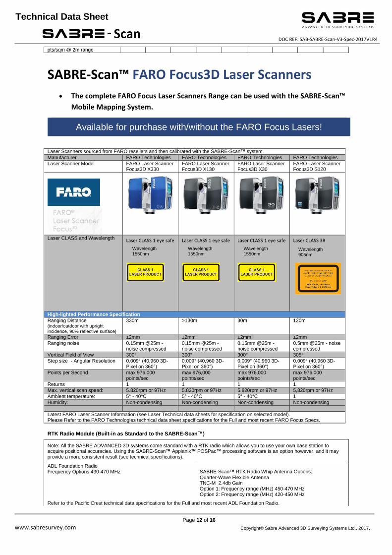
pts/sqm @ 2m range
SABRE-Scan™ FARO Focus3D Laser Scanners
The complete FARO Focus Laser Scanners Range can be used with the SABRE-Scan™
Mobile Mapping System.
Available for purchase with/without the FARO Focus Lasers! Laser Scanners sourced from FARO resellers and then calibrated with the SABRE-Scan™ system.
Manufacturer FARO Technologies FARO Technologies FARO Technologies FARO Technologies Laser Scanner Model FARO Laser Scanner
Focus3D X330 FARO Laser Scanner Focus3D X130
FARO Laser Scanner Focus3D X30
FARO Laser Scanner Focus3D S120
Laser CLASS and Wavelength Laser CLASS 1 eye safe
Laser CLASS 1 eye safe
Laser CLASS 1 eye safe
Laser CLASS 3R
High-lighted Performance Specification
Ranging Distance (indoor/outdoor with upright incidence, 90% reflective surface)
330m >130m 30m 120m
Ranging Error ±2mm ±2mm ±2mm ±2mm
Ranging noise 0.15mm @25m - noise compressed
0.15mm @25m - noise compressed
0.15mm @25m - noise compressed
0.5mm @25m - noise compressed
Vertical Field of View 300° 300° 300° 305°
Step size - Angular Resolution 0.009° (40,960 3D-Pixel on 360°)
0.009° (40,960 3D-Pixel on 360°)
0.009° (40,960 3D-Pixel on 360°)
0.009° (40,960 3D-Pixel on 360°)
Points per Second max 976,000 points/sec
max 976,000 points/sec
max 976,000 points/sec
max 976,000 points/sec
Returns 1 1 1 1
Max. vertical scan speed: 5.820rpm or 97Hz 5.820rpm or 97Hz 5.820rpm or 97Hz 5,820rpm or 97Hz
Ambient temperature: 5° - 40°C 5° - 40°C 5° - 40°C 1
Humidity: Non-condensing Non-condensing Non-condensing Non-condensing
Latest FARO Laser Scanner Information (see Laser Technical data sheets for specification on selected model). Please Refer to the FARO Technologies technical data sheet specifications for the Full and most recent FARO Focus Specs.
RTK Radio Module (Built-in as Standard to the SABRE-Scan™)
Note: All the SABRE ADVANCED 3D systems come standard with a RTK radio which allows you to use your own base station to acquire positional accuracies. Using the SABRE-Scan™ Applanix™ POSPac™ processing software is an option however, and it may provide a more consistent result (see technical specifications).
ADL Foundation Radio Frequency Options 430-470 MHz SABRE-Scan™ RTK Radio Whip Antenna Options:
Quarter-Wave Flexible Antenna TNC-M 2.4db Gain Option 1: Frequency range (MHz) 450-470 MHz Option 2: Frequency range (MHz) 420-450 MHz
Refer to the Pacific Crest technical data specifications for the Full and most recent ADL Foundation Radio.
Wavelength 1550nm
Wavelength 905nm
Wavelength 1550nm
Wavelength 1550nm

Page 13 of 16 www.sabresurvey.com
SABRE-Scan Technical Data Sheet DOC REF: SAB-SABRE-Scan-V3-Spec-2017V1R4
Technical Data Sheet
Copyright© Sabre Advanced 3D Surveying Systems Ltd., 2017.
SABRE-Scan™ Shipping / Transit Case Dimensions and Weights
SABRE-Scan™ and Kit Transit Cases
Main Items Size: External Dimensions (L X W X H) (m)
Weight
SABRE-Scan™ (i-NAV) Case
SABRE PN 07-00-0001-01-00 ZARGES CASE MPN 345294
SABRE-Scan™ (i-NAV™) Dual FARO
Primary GNSS Antenna
DMI Unit
L 0.90 x W 0.50 x H 0.38 (m), 28.5 kg (Empty Case 12.0 kg)
SABRE-Scan™ Kit Case
SABRE PN 07-00-0002-01-00 ZARGES CASE MPN 40702
General Kit and Equipment L 0.60 x W 0.40 x H 0.34 (m), 12.0 kg (Empty Case 6.0 kg)
Compliance
Certifications/Marks ,
Safety Standards:
EN61010-1: 2010 Safety requirements for electrical equipment for measurement, control and laboratory use – Part 1: General requirements.
EMC
Standards:
EN61326-1: 2013 Electrical equipment for measurement, control and laboratory use – Electromagnetic Compatibility (EMC)
CISPR11: 2009 +A1:2010 EN55011: 2009 +A1: 2010 EN61000-3-2: 2006 + A1:2009 + A2: 2009 EN61000-3-3: 2008 EN61000-4-2: 2009 EN61000-4-3: 206 + A1: 2008 + A2: 2010 EN/IEC61000-4-8: 2010 EN61000-4-4: 2004 + A1: 2010 EN61000-4-5: 2006 EN61000-4-6:2009
FCC Standards:
Equipment Classification: FCC Class A, CFR47: 2011 Part 15 Sub part B (US Federal code or regulation) consisting of Clause 15.109 (Class A). 15.109 Radiated emission limits.
Software
The following software comes as standard with a purchased SABRE-Scan™ System.
Software Application Type of Licence
SABRE-Scan™ SABRE Point-Stream MM™ Controller Software
SABRE Point stream (Positioning and laser processing software).
SABRE GTT™ Sabre time-tagging software.
Sabre point stream (Sabre sonar/Laser/positioning software).
Micro Dongle
QPS QINSY Software Micro Dongle
Applanix™ POSPac™ Post-Processing Software Micro Dongle / Node-Locked Licence
Pacific Crest ADL Foundation Radio Module Configuration Software
Software available for download on the Pacific Crest Website.
Other Kit Items
Overview of equipment included with the kit:
2 Boxes and a Come as Standard with the SABRE-Scan™ System.
Choice of Rack Options Available.

Page 14 of 16 www.sabresurvey.com
SABRE-Scan Technical Data Sheet DOC REF: SAB-SABRE-Scan-V3-Spec-2017V1R4
Technical Data Sheet
Copyright© Sabre Advanced 3D Surveying Systems Ltd., 2017.
Optional Equipment
Figure 5: DMI (Distance Measuring Instrument). Figure 6: Ladybug®5/5+ Camera and SABRE attachments.
Camera System/Equipment
Recommended 360 Camera Options to use with the SABR-Scan™ mobile mapping systems:
360 Camera Imagery – Georeferenced with the SABRE-Scan™ SABRE Point-Stream™ MM™
Common Camera Options available: Ladybug®5/5+ and Ladybug®3 Cameras
Alternatively other cameras can be integrated (e.g. other machine vision cameras, etc) In the table below high-lighted technical specification data attributes below;
Product Name/Description: Ladybug®5 - 30 MP,
360 Video Streaming Ladybug®3 Camera 360 Video Streaming
Brand:
Photo resolution [mp] : 30 MP (5 MP x 6 sensors)
12 MP (2 MP x 6 sensors)
Number of lenses: 6 6
Geo-referencing of images: Y with SABRE-Scan™ Y with SABRE-Scan™
Imaging Optics and Sensor Camera sensor Type Sony ICX655 CCD, 2/3", Sony ICX274 CCD x6, 1/1.8",
MP per sesnor 5.0MP per sensor 2.0MP per sensor
Shutter Type: Global Shutter Global Shutter
Spectral Bands [PAN, RGB, NIR, CIR]: RGB RGB
Resolution per Sensor size [.. x .. pixels]: 2048 x 2448 px 1600 x 1200 px
Pixel size [micrometer]: 3.45 μm 4.4 μm
FoV per camera [deg]: 113.4 >80% of full sphere
Maximum frames/sec. per camera : 10 fps 6.5 fps
Focal length of lenses [mm]: 4.4mm 3.3mm
Export formats: *.PGR *.JPEG *.PGR *.JPEG
General Weight [kg]: 3 kg 2.414 kg
Length [m]: 0.197 mm 0.122 mm (without lens hoods)
Width [mm]: 0.197 mm 0.122 mm (without lens hoods)
Depth [mm]: 0.160 mm 0.141 mm (without lens hoods)
Environmental protection: IP65 WEATHER-RESISTANT
Power Supply
External power requirements 12-24V 12V Power consumption [W]: 13W 7.2W
Data Storage, Software and Connectivity
USB: Y - USB 3 FireWire 800 (1394b) cable
Image data output and formats: RAW (*.PGR) or JPEG RAW (*.PGR) or JPEG
Main applications: Applications in geographic information systems (GIS); mobile vehicle-based photogrammetry. Georeferenced imaging.
wide variety of industries, including: large scale GIS systems for location-based visualizations, such as street-level viewing, and geographical mapping; high end security and surveillance applications; city planners for inventory and traffic scene analysis; and the entertainment industry for lighting models, full dome projection content, and other immersive experiences.
Ladybug®5/5+ Panoramic Video Camera
Ladybug®5/5+ SABRE Bracket SABRE 0.5m Mast
Ladybug®5/5+ SABRE Bracket SABRE 0.5m Mast
DMI Unit
DMI Rod
Removable Magnetic Mount Rod Bracket

Page 15 of 16 www.sabresurvey.com
SABRE-Scan Technical Data Sheet DOC REF: SAB-SABRE-Scan-V3-Spec-2017V1R4
Technical Data Sheet
Copyright© Sabre Advanced 3D Surveying Systems Ltd., 2017.
Other Optional Accessories Optional: DMI (Distance Measurement Instrument)
DMI (computes wheel rotation information to aid vehicle positioning. DMI Unit with wheel fitment kit specific to the wheel and stud size. and DMI Cable assembly to connect to SABRE-Scan™ (i-NAV) Unit DMI Vehicle Attachment Options: Permanent Vehicle Arch Fixing Kit provided with SABRE-Scan™ Kit or Optional Removable Magnetic Mount available.
Optional: Ladybug®5/5+ Panoramic Video Camera Compatible with SARBE Time-Tagging
360 panoramic camera : The high-resolution Ladybug®5/5+ panoramic camera system has 6 5 Mega-Pixel cameras that enable the system to collect images for more than 80% of a full sphere. Images are fully synchronized and geo-referenced.
SABRE Ladybug®5/5+ Bracket and SABRE 360 Camera 0.5m Mast. SABRE Ladybug®5/5+ Custom Mounting, to be used/fitted on SABRE-Scan™ Roof-Rack Assembly.
Field Operations Work Station Laptop
Optional: RTK Radio Link and GNSS Base Station Equipment
Notes:
(*) Measurement Speed (pts/sec): 500,000 for standard used FARO Focus Quality and Resolution Settings
* Product appearance and Specifications subject to change without notice.
FARO Focus Weight Without Battery 4.2 Kg
Abbreviations/Acronym: LiDAR Light Detection And Ranging, DMI (Distance Measurement Instrument),
SABRE mnemonics: i-NAV Unit (Inertial Navigation Unit).

Page 16 of 16 www.sabresurvey.com
SABRE-Scan Technical Data Sheet DOC REF: SAB-SABRE-Scan-V3-Spec-2017V1R4
Technical Data Sheet
Copyright© Sabre Advanced 3D Surveying Systems Ltd., 2017.
Brathens ECO-Business Park Hill of Brathens, Banchory Kincardineshire United Kingdom AB31 4BW
UK Company Registration No. SC539254
http://www.sabresurvey.com/
Email: [email protected]
Tel: +44-1330-820225
Land Mobile Mapping and Unmanned Aerial survey Systems
SABRE-Scan™ Mobile Mapping Product Solution | To Find out More Visit Us at WWW.SABRESURVEY.CO.UK
Sabre Advanced 3D Surveying Systems Ltd | +44 (0) 1330 820 225 | [email protected]
Sabre Advanced 3D Surveying Systems Ltd © SABRE 2017 DOC REF: SAB-S-S-OL-2017V1R4