mobile radiomodem installation guide version...
TRANSCRIPT
GeminiPD+
Mobile RadiomodemInstallation Guide
Version 2.11
The entire contents of this manual and the Radio Installation Softwaredescribed in this manual are copyright 2004 by DATARADIO Inc.®
Copyright DATARADIO Inc.October, 2004
Part no.: 120 20120-211
120 20120-211 GeminiPD+ Installation GuideII
Table of Contents
1. PRODUCT OVERVIEW...................................................................................................................................1
1.1 INTENDED AUDIENCE ........................................................................................................................................11.2 GENERAL DESCRIPTION.....................................................................................................................................1
1.2.1 Features ...................................................................................................................................................21.2.2 Configuration...........................................................................................................................................2
1.3 FACTORY TECHNICAL SUPPORT ........................................................................................................................31.4 PRODUCT WARRANTY.......................................................................................................................................31.5 REPLACEMENT PARTS .......................................................................................................................................3
1.5.1 Factory Repair.........................................................................................................................................31.6 UNPACKING.......................................................................................................................................................4
2. INSTALLATION................................................................................................................................................4
2.1 PLANNING THE INSTALLATION ..........................................................................................................................42.1.1 Overview..................................................................................................................................................42.1.2 Location ...................................................................................................................................................42.1.3 Cable Path ...............................................................................................................................................4
2.2 WARNINGS ........................................................................................................................................................52.2.1 RF Radiation warning .............................................................................................................................52.2.2 Interference with vehicular electronics ...................................................................................................52.2.3 Secure mounting ......................................................................................................................................52.2.4 Explosive environments ...........................................................................................................................52.2.5 Installation in vehicles powered by liquefied gas. ...................................................................................5
2.3 PHYSICAL UNIT .................................................................................................................................................62.3.1 Recommended tools and supplies ............................................................................................................62.3.2 Physical mounting of GeminiPD+ ..............................................................................................................6
2.4 ELECTRICAL INSTALLATION ..............................................................................................................................72.4.1 Electrical requirements ...........................................................................................................................72.4.2 Routing of power cable............................................................................................................................7
2.5 ANTENNA ..........................................................................................................................................................82.5.1 Recommended tools and supplies ............................................................................................................82.5.2 Antenna Installation ................................................................................................................................9
2.6. COMPLETING THE PHYSICAL INSTALLATION. ..............................................................................................102.7. CHECKING OUT NORMAL OPERATION..........................................................................................................10
3. OPERATING DESCRIPTION .......................................................................................................................11
3.1 FRONT & REAR PANELS ..................................................................................................................................113.2 DTE PORT INTERFACE ....................................................................................................................................12
3.2.1 RS-232 Interface Signal Levels..............................................................................................................12
4. TROUBLE-SHOOTING AND TESTING .....................................................................................................13
4.1 EQUIPMENT REQUIRED....................................................................................................................................134.1.1 WinRIS ...................................................................................................................................................13
4.2 BASIC TESTS ...................................................................................................................................................134.3 ADDITIONAL TEST DETAILS .............................................................................................................................15
4.3.1 TX Deviation..........................................................................................................................................154.3.2 GPS Test ................................................................................................................................................154.3.3 RF Data Link Test..................................................................................................................................16
5. SPECIFICATIONS ..........................................................................................................................................17
120 20120-211 GeminiPD+ Installation GuideIII
FIGURE 1 - MOUNTING PLATE AND SLOT DIMENSIONS....................................................................................................6FIGURE 2 - BRACKET INSTALLATION..............................................................................................................................7FIGURE 3 - DC POWER CONNECTOR ..............................................................................................................................7FIGURE 4 - ANTENNA SPACING.......................................................................................................................................9FIGURE 5 - FRONT AND REAR PANELS ..........................................................................................................................11
TABLE 1 - GEMINIPD+ LEDS INDICATIONS ....................................................................................................................12TABLE 2 - DTE PORT PIN FUNCTIONS...........................................................................................................................12TABLE 3 - RS-232 SIGNAL LEVELS..............................................................................................................................12TABLE 4 – TEST CHECKLIST.........................................................................................................................................14TABLE 5 - TX DEVIATION............................................................................................................................................15
APPENDIX 1 - "OFFICER REQUIRES ASSISTANCE" ALARM FUNCTION.....................................................................19APPENDIX 2 – SPECIAL APPLICATION – CARRIER SENSE (CS-DBA).......................................................................20
120 20120-211 GeminiPD+ Installation GuideIV
What's New in this version
History
Version 2.11, October 2004
• Adds that firmware is field-upgradable using WinRIS, section 1.2.1“Features”, section 1.2.2 “Configuration”, and section 4.1.1 “Win-RIS”.
• Amends GPS antenna testing, section 4.3.2
• Adds ISO Registration visibility
Version 2.10, May 2004
• Addition of PARALLEL DECODE ™ visibility
• Addition of “12-channel high efficiency GPS receiver” information to“Feature” list, section 1.2.1
• Addition of warning to the “The DC Power lead must be unswitched” insection 2.4.2 for “NMS / Mobile Diagnostics” users stating that thisis mandatory to let the unit save its radio diagnostics and statis-tics at shutdown time.
• Addition of “Standby current for Ignition OFF” to the Specificationssection.
Version 2.00, May 2003
• Introduction of xRC8FSK bit rates (43.2, 24 and 21.6 kb/s)
• Introduction of Carrier Sense (CS-DBA) feature.
Version 1.04, January 2003
• Introduction of GeminiPD+ in 900 MHz frequency band.
• Changed the manual format from 2 to 1 column
• Revised and updated Section 5 (Specifications)
Version 1.00, May 2002
• Introduction of GeminiPD+ running data rate up to 32kb/s

120 20120-211 GeminiPD+ Installation GuideV
DATARADIO is a registered trademark, Gemini, Gemini PD, and PARALLEL DECODE are trademarks ofDataradio Inc
120 20120-211 GeminiPD+ Installation GuideVI
Definitions
The following terms are used throughout this document.
Item Definition DCE Data Communications Equipment. This designation defines the direction (input
or output) of the various RS-232 interface signals. Modems are always wired asDCE.
DTE Data Terminal Equipment. This designation defines the direction (input or out-put) of the various RS-232 interface signals. Most user equipment, as well asPCs, are wired as DTE.
GCU Control Unit board used in GeminiPD products GeminiPD High-specification mobile radiomodem. Limited to 25.6 kb/s.
PD = PARALLEL DECODE ™ technology GeminiPD+ Mobile radiomodem on-air compatible with GeminiPD products. Runs up to 43.2
kb/s
GeminiPD+ Lite GeminiPD+ mobile radiomodem without GPS feature HDX Half Duplex. A unit that uses separate transmit and receive frequencies, but
which may not transmit and receive simultaneously. RS-232 Industry–standard interface for data transfer. WinRIS Windows © Radio Installation Software. This software allows basic tests and
unit configuration.
120 20120-211 GeminiPD+ Installation Guide1
1. PRODUCT OVERVIEWThis document provides the information required for the installation, operation, and verification of theDATARADIO® GeminiPD+ ™ radiomodems.
1.1 Intended AudienceThis document is designed for use by engineering design, installation, and maintenance personnel.
1.2 General DescriptionGeminiPD+ mobile radiomodem products are aimed at the public safety and public utility markets to meetdemand for high speed and high throughput. They integrate all the necessary hardware for data-only vehicularinstallations up to but not including the laptop PC and its application software.
Example of applications are:1. Database inquiry systems.
Small number of brief messages, (usually from the mobile station) with fairly long responses.
2. Computer-aided dispatch (CAD).Large number of messages, (usually from the base station) with very brief responses.
3. Automatic Vehicle Location (AVL).Using built-in GPS receiver, determines position, speed and direction of fleet members.
GeminiPD+ radiomodems are made-up of:• A main transceiver • An auxiliary receiver for PARALLEL DECODE ™ (patents pending) technology • A power amplifier (40-Watt for UHF, 35-Watt for 800 MHz, 25-Watt for 900MHz models)• A Gemini Control Unit (GCU) with DSP driven modem • An integrated OEM GPS receiver.1
DATARADIO is a registered trademark, Gemini, Gemini PD, and PARALLEL DECODE are trademarks ofDataradio Inc
1 The Gemini PD+ Lite model has no GPS.
120 20120-211 GeminiPD+ Installation Guide2
1.2.1 Features• One-piece integrated design in a rugged die-cast aluminum chassis.• PARALLEL DECODE ™ (PD) technology featuring dual receivers for added decode sensitivity
in multi-path and fading environments.• Sophisticated DSP-based modem design provides added system performance, fewer retries and
more effective throughput.• Automatic channel changing for improved roaming capabilities.• Built–in, up to 16-channel flash-programmable synthesized radio transceiver with automatic
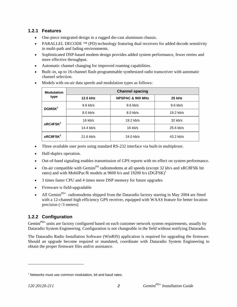
channel selection.• Models with on-air data speeds and modulation types as follows:
Channel spacingModulationtype 12.5 kHz NPSPAC & 900 MHz 25 kHz
9.6 kb/s 9.6 kb/s 9.6 kb/sDGMSK1
8.0 kb/s 8.0 kb/s 19.2 kb/s
16 kb/s 19.2 kb/s 32 kb/sxRC4FSK1
14.4 kb/s 16 kb/s 25.6 kb/s
xRC8FSK1 21.6 kb/s 24.0 kb/s 43.2 kb/s
• Three available user ports using standard RS-232 interface via built-in multiplexer.
• Half-duplex operation.
• Out-of-band signaling enables transmission of GPS reports with no effect on system performance.
• On-air compatible with GeminiPD radiomodems at all speeds (except 32 kb/s and xRC8FSK bitrates) and with MobilPac/R models at 9600 b/s and 19200 b/s (DGFSK)1
• 3 times faster CPU and 4 times more DSP memory for future upgrades
• Firmware is field-upgradable
• All GeminiPD+ radiomodems shipped from the Dataradio factory starting in May 2004 are fittedwith a 12-channel high efficiency GPS receiver, equipped with WAAS feature for better locationprecision (<3 meters)
1.2.2 ConfigurationGeminiPD+ units are factory configured based on each customer network system requirements, usually byDataradio System Engineering. Configuration is not changeable in the field without notifying Dataradio.
The Dataradio Radio Installation Software (WinRIS) application is required for upgrading the firmware.Should an upgrade become required or mandated, coordinate with Dataradio System Engineering toobtain the proper firmware files and/or assistance.
1 Networks must use common modulation, bit and baud rates.
120 20120-211 GeminiPD+ Installation Guide3
1.3 Factory Technical Support The Technical Support departments of DATARADIO® provide customer assistance on technical prob-lems and serve as an interface with factory repair facilities. They can be reached in the following ways:
DATARADIO Inc. 5500 Royalmount Ave, suite 200 Town of Mount Royal Quebec, Canada H4P 1H7
Technical support hours: Monday to Friday 9:00 AM to 5:00 PM, Eastern Time
phone: +1 514 737-0020fax: +1 514 737-7883 Email address: [email protected]
DATARADIO Corp. 6160 Peachtree Dunwoody RD., suite C-200 Atlanta, Georgia 30328
Technical support hours: Monday to Friday 9:00 AM to 5:00 PM, Eastern Time
phone: 1 770 392-0002 fax: 1 770 392-9199
Email address: [email protected]
1.4 Product Warranty Warranty information may be obtained by contacting your sales representative.
1.5 Replacement Parts This product is not field-serviceable, except by the replacement of a complete unit. Specialized equipmentand training is required to repair the GCU board and radio modules.
Contact Technical Support for service information before returning equipment. A Technical Support rep-resentative may suggest a solution eliminating the need to return equipment.
1.5.1 Factory Repair When returning equipment for repair, you must request an RMA (Returned Material Authorization) num-ber. The Tech Support representative will ask you several questions to clearly identify the problem.Please give the representative the name of a contact person, who is familiar with the problem, shouldquestions arise during servicing of the unit.
Customers are responsible for shipping charges for returned units. Units in warranty will be repaired freeof charge unless there is evidence of abuse or damage beyond the terms of the warranty. Units out of war-ranty will be subject to service charges. Information about these charges is available from Technical Sup-port.
120 20120-211 GeminiPD+ Installation Guide4
1.6 UnpackingWhen ready for installation, carefully unpack your GeminiPD+ kit (p/n 023 6000-001) shipping carton andidentify each item as listed below:
• One GeminiPD+ radiomodem• Installation mounting bracket • Power cable – 22 feet (6.7 meters)• Small parts kit
If damage has occurred to the equipment during shipment, file a claim with the carrier immediately.
2. Installation
2.1 Planning the Installation
2.1.1 OverviewTo ensure trouble-free, efficient installation, start by inspecting the vehicle to determine the optimum po-sition for the GeminiPD+ unit and its antennas as well as routing of all associated cabling and wiring.
2.1.2 LocationOften, installations in cars are done in the trunk, underneath the back window ledge or on the trunk floor.In vans and small trucks, it is usually done in the back of the vehicle. In large vehicles, it is often done inthe front cabin.
Be sure to place the GeminiPD+ unit in such a way that:• The LEDs can be seen (as an aid in troubleshooting)• Access to the antenna DE-9 connectors is possible without removing the unit • Sufficient air may flow around the unit to provide adequate cooling
The GeminiPD+ product is not fully waterproof, therefore it should be mounted sufficiently away from anopened trunk lid or opened tailgate, windows or doors to avoid exposure to rain and/or snow. It alsominimizes the chance that material can be accidentally thrown on the unit or of someone bumping againstit.
2.1.3 Cable PathTry to route the cables away from locations where they would be exposed to heat (exhaust pipes, muf-flers, tailpipes, etc.), battery acid, sharp edges, mechanical damage or where they would be a nuisance toautomobile mechanics, the driver or the passengers.
Keep wiring away from automotive computer modules, other electronic modules and ignition circuits tohelp prevent interference between these components and radio equipment.
Try using existing holes in firewall and trunk wall and the channels above and below or beneath thedoors, channels through doors and window columns that are convenient to run cables and wires.Whenever possible, install conduit in which to run the cables.
120 20120-211 GeminiPD+ Installation Guide5
2.2 Warnings Before starting installation, review all of the following warnings.
2.2.1 RF Radiation warningRecommended safety guidelines for the human exposure to radio frequency electromagnetic energy arecontained in the Canadian Safety Code 6 and the Federal Communications Commission (FCC) Bulletin65. Proper installation of the transceiver antenna of GeminiPD+ products as summarized in section 2.5 willresult in user exposure substantially below the recommended limits for the general public.
Qualified personnel must do all antenna installations. See section 2.5 for recommended positioning.Transmissions when persons or animals outside the vehicle are within two feet of the antenna may resultin radio energy radiation burns or related injuries.
2.2.2 Interference with vehicular electronicsCertain vehicle electronic devices may be prone to malfunction due to lack of protection from radio fre-quency energy present when transmitting. It includes, and is not limited to:
• Electronic fuel injection systems• Electronic anti-skid braking systems• Electronic cruise control systems
If the installation vehicle contains such equipment, consult the dealer for the make of vehicle and enlisthis aid in determining if such electronic circuits will perform normally when the radio is transmitting.
2.2.3 Secure mountingFor vehicle occupant(s) safety, mount GeminiPD+ radiomodems securely so that the unit will not breakloose in case of violent maneuvers or an accident.
2.2.4 Explosive environmentsOperation of vehicular radio transmitters in explosive environments may be hazardous and conventionalsafety precautions must prevail. These include and are not limited to:
• Transmitting while fuelling the vehicle. Do not carry fuel containers in the same compartment asGeminiPD+.
• Dynamite blasting caps may explode when transmitting radio operation takes place within 500feet. Always obey the “Turn Off Two-Way Radios” signs posted at sites where dynamite is beingused.
If transporting blasting caps:a) Carry the blasting caps in an appropriate metal container having a soft cushioning lining.b) Suppress transmissions whenever the blasting caps container is being loaded or unloaded into or
from the vehicle.Check applicable local bylaws.
2.2.5 Installation in vehicles powered by liquefied gas.GeminiPD+ radiomodems installation in vehicles powered by liquefied petroleum gas with the LP-gascontainer in the trunk or other sealed-off space within the interior of the vehicle must conform to the Na-tional Fire Protection Association Standard NFPA 58 which requires:
• Space containing radio equipment shall be isolated by a seal from the space containing the LP-gascontainer and its fittings.
• Outside filling connections shall be used for the LP-gas container.The LP-gas container space shall be vented to the outside of the vehicle.
120 20120-211 GeminiPD+ Installation Guide6
2.3 Physical Unit
2.3.1 Recommended tools and supplies• Electric drill for mounting holes• Hammer and center punch• Tie-wraps• Drills and circle cutters as needed according the size of screws (or nuts and bolts) used.• In-line “Power meter” capable of measuring forward and reflected power at the operating fre-
quency of the radio.
2.3.2 Physical mounting of GeminiPD+
a) Start by running all the cables (DC power, PC RS-232 as well as all antennas cabling) prior tomounting GeminiPD+ unit to assure the feasibility of the planned cable routing.
b) Be sure to leave sufficient slack in each cable so the GeminiPD+ unit may be removed from themounting bracket for servicing with the power applied and the antenna attached.
c) GeminiPD+ radiomodem is ready for installation. Cautions:
• When drilling mounting holes, be careful to avoid damaging some vital part of the vehi-cle such as fuel tanks, transmission housing etc. Always check how far the mountingscrews extend below the mounting surface prior to installation.
• Use of drill bit stops is highly recommended. • After drilling, remove all metal shavings before installing screws.• Do not overtighten self-tapping screws.
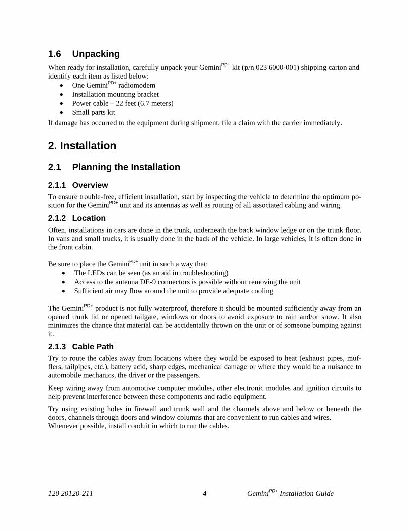
1. Once you have found a suitable mounting position for GeminiPD+ radiomodem, hold the unit and theunattached mounting bracket in the proposed mounting position and check that there is clearance be-hind the unit for the heatsink, cables, etc. Check that the position provides a large enough flat surfacethat the bracket will not be distorted when installed.
Figure 1 - Mounting plate and slot dimensions
2. Using the installation bracket as a template, mark the four locations for drilling (see Figure 1). Again,ensure that drilling at the selected points is safe and will not cause damage.
3. Indent the drilling positions with a center punch. 4. Drill holes sized for the self-tapping screws or for the nuts, bolts and lock washers used.
Caution: Slightly reduce the size of the drilled holes when using self-tapping screws in thin metal.
2.5"
6.0"
1.0"0.2"
120 20120-211 GeminiPD+ Installation Guide7
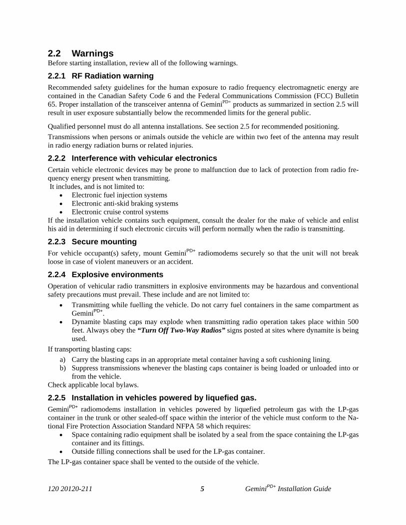
Figure 2 - Bracket installation
5. Install the bracket without distorting (see Figure 2).6. Securely mount GeminiPD+ unit to the installed bracket using the four supplied 8x40 black machine
screws. 7. Drill any additional holes as required for routing all cables and fit holes with suitable grommets or
bushings whenever required.
2.4 Electrical installation2.4.1 Electrical requirementsGeminiPD+ units are designed to operate from a 13.8Vdc nominal car battery (negative ground) and re-quire currents up to 12.0A. They will tolerate a supply voltage range of 10.9 volts to 16.3 volts.In vehicles with a 24 VDC electrical system (mostly in trucks), it is essential to provide a suitably rated24/12 VDC converter to isolate the unit from the battery and protect it against excessive voltage.Warnings:
Always disconnect GeminiPD+unit’s DC power lead before connecting a second battery, usingpower from another vehicle or power boosting (e.g. when “jump starting” the vehicle).
2.4.2 Routing of power cable 1. Start by disconnecting the vehicle’s battery unless specifically prohibited from doing so by the
customer, vehicle manufacturer, agent or supplier.Note:
In this event, exercise extreme caution throughout the installation and fit the fuse onlywhen the installation is complete.
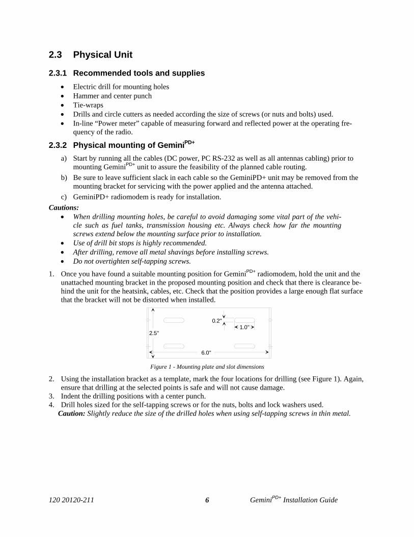
2. The 22-foot (6.7 meters) power cable consists of three wires attached to a Packard Electric “Weather-Pack” connector (DC power Connector, see Figure 3).
Figure 3 - DC Power Connector
The DC Power connector has:• At position “A”, the smaller red switch-sense wire (commonly to ignition)• At position “B”, the blue ground wire • At position “C”, a larger red B+ DC power wire (MUST be unswitched)
3. Place this connector at the GeminiPD+ radio’s power input location. Do not connect at this time.
A
B
C
IGNITION(Small red wire)
GROUND(Blue wire)
13.8VDC B+ (Fused Red wire) SEAL
(DO NOT REMOVE)

120 20120-211 GeminiPD+ Installation Guide8
4. Carefully route both the B and the C wires to where the in-line fuse holder will be installed, usually asclose to the vehicle’s battery as practicable. Ensure that leads do not chafe on any metal part(s). Se-cure the wires at several locations along their length.Caution:
Use proper crimping tool. Common pliers are NOT acceptable.
Warning:The DC Power lead must be unswitched. For “NMS / Mobile Diagnostics” users, this is manda-tory to let the unit save its radio diagnostics and statistics at shutdown time. Turning the unitOFF by switching the main DC power input instead of the ignition-sense results in radio diag-nostics/statistics becoming corrupted or totally lost during power-down / power-up cycles
5. Insert the negative (blue) lead into one of the appropriate connector lug and crimp solidly.
6. Repeat the step above for the red DC power lead.
7. Attach the positive lead at the battery positive terminal. Attach the negative wire at the vehicle end ofthe battery ground cable.
If the negative cable is connected directly to the battery negative terminal, it should be fusedin case of failure of the vehicle’s ground cable.
Ensure tight and secure connections.
8. Fasten the fuse holder and leads.
9. Carefully route the “A” wire to where the connection will be made for switch sensing. Depending onyour network requirements, select the relevant option from the four listed below.
a) Connect to “Ignition” to have the GeminiPD+ unit turn ON and OFF dependent on the vehicle’signition key.
b) Connect to “Accessory” if you wish the GeminiPD+ unit to operate when the engine is not running,but still dependent on the ignition key.
c) Connect to a user-supplied control switch.
d) In installations equipped with a “ChargeGuard”, connect only the switch-sense “A” lead to thecontrolled-side of the ChargeGuard. The DC Power lead must NOT be switched.
10. Make appropriate connections. Cautions:
Where scraping to bare metal was required, and at the battery posts where wire ends and lugsmay be exposed, apply anti-corrosion compound. Insert the fuse only when installation is complete and ready to test.
11. At the GeminiPD+ radiomodem position, neatly coil cable slack and attach securely.
2.5 Antenna The main transmitter antenna must be vehicle-mounted to provide a separation distance of 50 cm or morefrom all persons and the antenna gain must not exceed 5dBi (with a 1.6dB cable loss).
2.5.1 Recommended tools and supplies• circle cutter, hole saw or socket punch for antenna• Mini-UHF Crimp tool Planning
Referring to Figure 4, GeminiPD+ radiomodems commonly uses three separate antennas:
120 20120-211 GeminiPD+ Installation Guide9
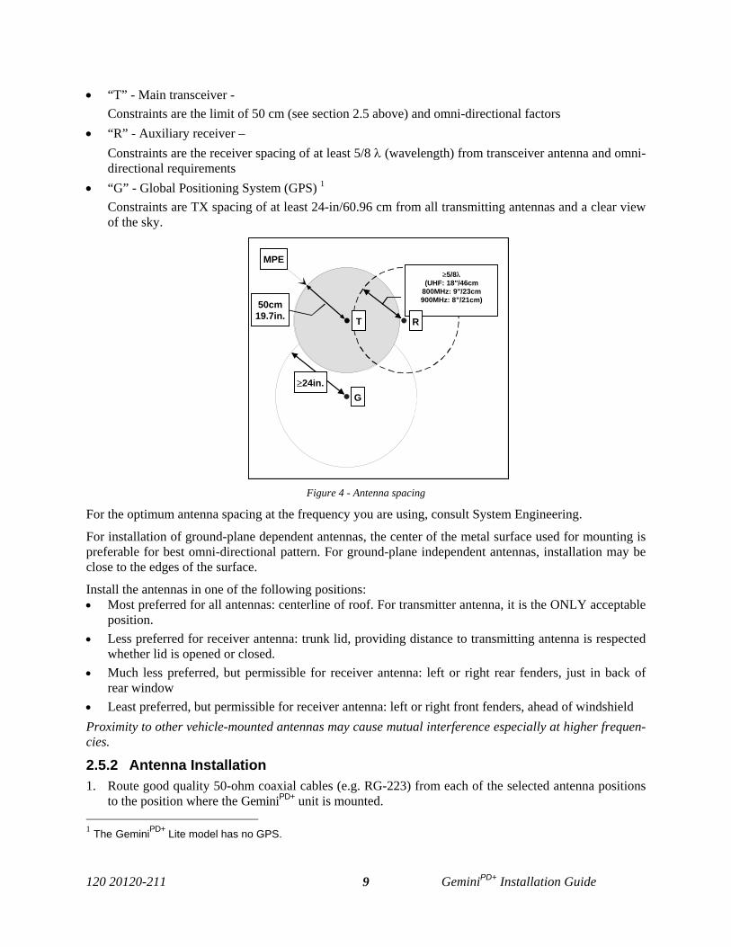
• “T” - Main transceiver - Constraints are the limit of 50 cm (see section 2.5 above) and omni-directional factors
• “R” - Auxiliary receiver – Constraints are the receiver spacing of at least 5/8 λ (wavelength) from transceiver antenna and omni-directional requirements
• “G” - Global Positioning System (GPS) 1
Constraints are TX spacing of at least 24-in/60.96 cm from all transmitting antennas and a clear viewof the sky.
Figure 4 - Antenna spacing
For the optimum antenna spacing at the frequency you are using, consult System Engineering.
For installation of ground-plane dependent antennas, the center of the metal surface used for mounting ispreferable for best omni-directional pattern. For ground-plane independent antennas, installation may beclose to the edges of the surface.
Install the antennas in one of the following positions: • Most preferred for all antennas: centerline of roof. For transmitter antenna, it is the ONLY acceptable
position. • Less preferred for receiver antenna: trunk lid, providing distance to transmitting antenna is respected
whether lid is opened or closed. • Much less preferred, but permissible for receiver antenna: left or right rear fenders, just in back of
rear window• Least preferred, but permissible for receiver antenna: left or right front fenders, ahead of windshieldProximity to other vehicle-mounted antennas may cause mutual interference especially at higher frequen-cies.
2.5.2 Antenna Installation1. Route good quality 50-ohm coaxial cables (e.g. RG-223) from each of the selected antenna positions
to the position where the GeminiPD+ unit is mounted. 1 The GeminiPD+ Lite model has no GPS.
G
MPE≥5/8λ
(UHF: 18"/46cm800MHz: 9"/23cm900MHz: 8”/21cm)
RT50cm
19.7in.
≥24in.
120 20120-211 GeminiPD+ Installation Guide10
2. Terminate the end at each of the antenna positions with the appropriate connector for the antennaused and make the connection.
3. At the GeminiPD+ radiomodem position, cut the three cables to length and terminate with the appropri-ate plug. For the transceiver and the auxiliary cables, use a Mini-UHF crimp plug using an appropri-ate crimping tool. For the GPS, use a SMA connector.
4. Positively identify the transceiver mini-UHF plug and connect to the left rear of GeminiPD+ unit.
5. Positively identify the auxiliary receiver mini-UHF plug and connect to the front left of GeminiPD+
unit to the RX position.
6. Connect the SMA connector to the GPS* position below the auxiliary connector position.
7. Do not skip this last step, trust us; it is an important one. To complete the installation, tie-wrap to-gether the auxiliary and the GPS 1 antenna cables at a point about two inches in front of the unit. Itwill be much easier hereafter to correctly identify which mini-UHF plug goes where. You DO NOTwant to cross the auxiliary plug with the transceiver plug.
2.6. Completing the physical Installation.To complete the physical installation and prior to testing GeminiPD+ radiomodems:
• Connect DC Power cable’s connector to GeminiPD+ unit until you hear a click as the two partssnap together.
• Re-check that all other connections are secure (antennas, PC, etc.)• Switch vehicle ignition ON.
You are now ready to check for normal operation and to run the Radio Installation Software (WinRIS)program for testing or trouble-shooting.
2.7. Checking out Normal operationCheck that the vehicle ignition is ON.
1. Check for proper operation of the GeminiPD+ radiomodem LEDs as per Table 1 on page 12.
2. Using the WinRIS program and an in-line wattmeter, check forward & reverse power to confirm mainantenna installation (as per section 4).
3. Using WinRIS, check the RF Data Link with a base station that can be heard (see section 4.3.3).
If user application and its base station are available, test the installation by going through a normal se-quence of transmitting and receiving messages.
1 The GeminiPD+ Lite model has no GPS.
120 20120-211 GeminiPD+ Installation Guide11
3. Operating Description
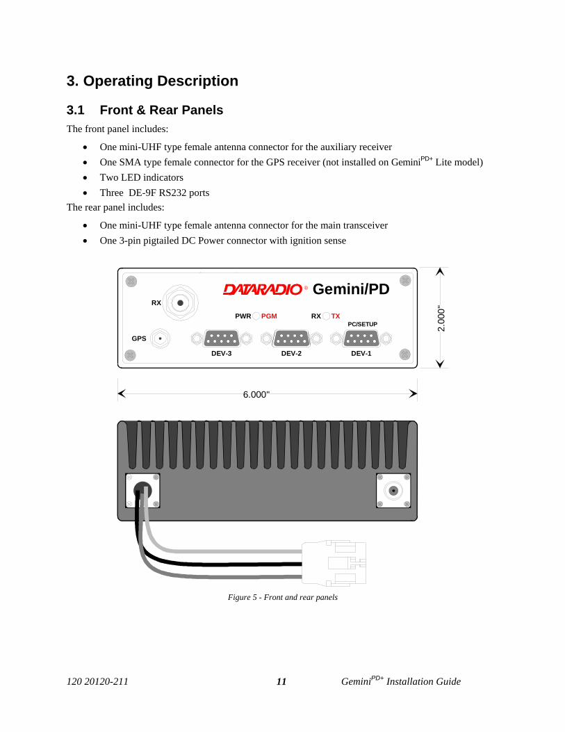
3.1 Front & Rear PanelsThe front panel includes:
• One mini-UHF type female antenna connector for the auxiliary receiver • One SMA type female connector for the GPS receiver (not installed on GeminiPD+ Lite model)• Two LED indicators• Three DE-9F RS232 ports
The rear panel includes:
• One mini-UHF type female antenna connector for the main transceiver • One 3-pin pigtailed DC Power connector with ignition sense
Figure 5 - Front and rear panels
®
RX TXPWR PGMPC/SETUP
DEV-1DEV-2DEV-3
RX
GPS
Gemini/PD
6.000"
2.00
0"
120 20120-211 GeminiPD+ Installation Guide12
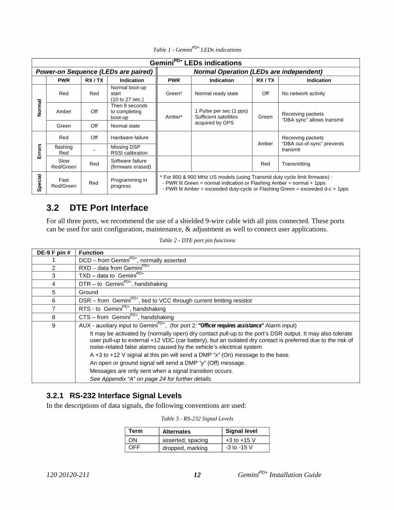
Table 1 - GeminiPD+ LEDs indications
GeminiPD+ LEDs indicationsPower-on Sequence (LEDs are paired) Normal Operation (LEDs are independent)
PWR RX / TX Indication PWR Indication RX / TX Indication
Red RedNormal boot-upstart(10 to 27 sec.)
Green* Normal ready state Off No network activity
Amber OffThen 8 secondsto completingboot-upN
orm
al
Green Off Normal state
Amber*1 Pulse per sec (1 pps)Sufficient satellitesacquired by GPS
Green Receiving packets“DBA sync” allows transmit
Red Off Hardware failure
flashingRed - Missing DSP
RSSI calibration
AmberReceiving packets“DBA out-of-sync” preventstransmit
Erro
rs
SlowRed/Green Red Software failure
(firmware erased) Red Transmitting
Spec
ial
FastRed/Green Red Programming in
progress
* For 800 & 900 MHz US models (using Transmit duty cycle limit firmware) :- PWR lit Green = normal indication or Flashing Amber = normal + 1pps- PWR lit Amber = exceeded duty-cycle or Flashing Green = exceeded d-c + 1pps
3.2 DTE Port InterfaceFor all three ports, we recommend the use of a shielded 9-wire cable with all pins connected. These portscan be used for unit configuration, maintenance, & adjustment as well to connect user applications.
Table 2 - DTE port pin functions
DE-9 F pin # Function1 DCD – from GeminiPD+, normally asserted2 RXD – data from GeminiPD+
3 TXD – data to GeminiPD+
4 DTR – to GeminiPD+, handshaking5 Ground6 DSR – from GeminiPD+, tied to VCC through current limiting resistor7 RTS - to GeminiPD+, handshaking8 CTS – from GeminiPD+, handshaking9 AUX - auxiliary input to GeminiPD+, (for port 2: “Officer requires assistance” Alarm input)
It may be activated by (normally open) dry contact pull-up to the port’s DSR output. It may also tolerateuser pull-up to external +12 VDC (car battery), but an isolated dry contact is preferred due to the risk ofnoise-related false alarms caused by the vehicle’s electrical system.A +3 to +12 V signal at this pin will send a DMP “x” (On) message to the base. An open or ground signal will send a DMP “y” (Off) message.Messages are only sent when a signal transition occurs.See Appendix “A” on page 24 for further details.
3.2.1 RS-232 Interface Signal LevelsIn the descriptions of data signals, the following conventions are used:
Table 3 - RS-232 Signal Levels
Term Alternates Signal levelON asserted, spacing +3 to +15 VOFF dropped, marking -3 to -15 V
120 20120-211 GeminiPD+ Installation Guide13
4. Trouble-Shooting and TestingThe checks described below should be done at annual intervals or whenever deterioration in per-formance is noted.
4.1 Equipment Required• 13.8 VDC (nominal) car battery, or
13.8 VDC/20A regulated power supply (In the case the unit is not installed in a vehicle)• In-line watt meter (50W range)• Radio service monitor (IFR or equivalent).• Cable with mini-UHF male connector to connect GeminiPD+ to the service monitor.• WinRIS version 4.14 or later as detailed in paragraph 4.1.1 below
4.1.1 WinRISTo find out how to launch the Windows-based Radio Installation Software (WinRIS), please referto the readme.txt file on the application’s installation diskette. This application is used for align-ment, firmware auto-upgrade, and is a system-testing tool. For functional details of the numerousbuttons and menu-selectable items available, please refer to the program’s context sensitive help.It is also possible to access the help information via the F1 key.
4.2 Basic Tests Recommended checks:1. Transmit and Reverse power output2. Carrier frequency error3. Frequency deviation4. Receivers RSSI Check5. RF Data Link test between a Gemini unit and a base station.6. GPS test (not required on GeminiPD+ Lite model).
- For checks 1 to 5, refer to Table 4 – Test Checklist below.- For check 6, refer to paragraph 4.3.2 - GPS Test.
Important note: Before proceeding make sure that the service monitor has been recentlycalibrated and has warmed up for at least the time specified by its manufacturer.
Some reported frequency and deviation problems have actually been erroneous indications fromservice monitors that have not adequately warmed up. This is particularly likely when field serv-ice is done during winter months.
120 20120-211 GeminiPD+ Installation Guide14
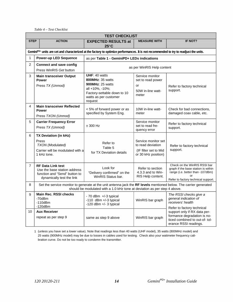
Table 4 – Test Checklist
TEST CHECKLISTSTEP ACTION EXPECTED RESULTS at
25°CMEASURE WITH IF NOT?
GeminiPD+ units are set and characterized at the factory to optimize performances. It is not recommended to try to readjust the units.
1 Power-up LED Sequence as per Table 1 - GeminiPD+ LEDs indications
2 Connect and save configPress WinRIS Get button
as per WinRIS Help content
3 Main transceiver OutputPowerPress TX (Unmod)
UHF: 40 watts 800MHz: 35 watts 900MHz: 25 wattsall +10%, -10%; Factory-settable down to 10watts as per customerrequest
Service monitorset to read poweror50W in-line watt-meter
Refer to factory technicalsupport.
4 Main transceiver ReflectedPowerPress TXON (Unmod)
< 5% of forward power or asspecified by System Eng.
10W in-line watt-meter
Check for bad connections,damaged coax cable, etc.
5 Carrier Frequency ErrorPress TX (Unmod) ± 300 Hz
Service monitorset to read fre-quency error
Refer to factory technicalsupport.
6 TX Deviation (in kHz)Press TXON (Modulated) Carrier will be modulated with a1 kHz tone.
Refer to Table 5
for TX Deviation details
Service monitor setto read deviation (IF filter set to Midor 30 kHz position)
Refer to factory technicalsupport.
7 RF Data Link testUse the base station addressfunction and “Send” button to
dynamically test the link
Look for “Delivery confirmed” on the
WinRIS Status bar.
Refer to section4.3.3 and to Win-RIS Help content.
Check on the WinRIS RSSI bargraph if the base station is withinrange (i.e. better than -107dBm)
orRefer to factory technical support.
8 Set the service monitor to generate at the unit antenna jack the RF levels mentioned below. The carrier generatedshould be modulated with a 1.0 kHz tone at deviation as per step 4 above.
9 Main Rec. RSSI checks-70dBm-110dBm-120dBm
- 70 dBm +/-3 typical-110 dBm +/-3 typical-120 dBm +/- 3 typical
WinRIS bar graph
10 Aux Receiverrepeat as per step 9 same as step 9 above WinRIS bar graph
The RSSI checks give ageneral indication ofreceivers' healthRefer to factory technicalsupport only if RX data per-formance degradation is no-ticed combined to out-of- tol-erance RSSI readings.
1 (unless you have set a lower value). Note that readings less than 40 watts (UHF model), 35 watts (800MHz model) and25 watts (900MHz model) may be due to losses in cables used for testing. Check also your wattmeter frequency cali-bration curve. Do not be too ready to condemn the transmitter.
120 20120-211 GeminiPD+ Installation Guide15
4.3 Additional test details
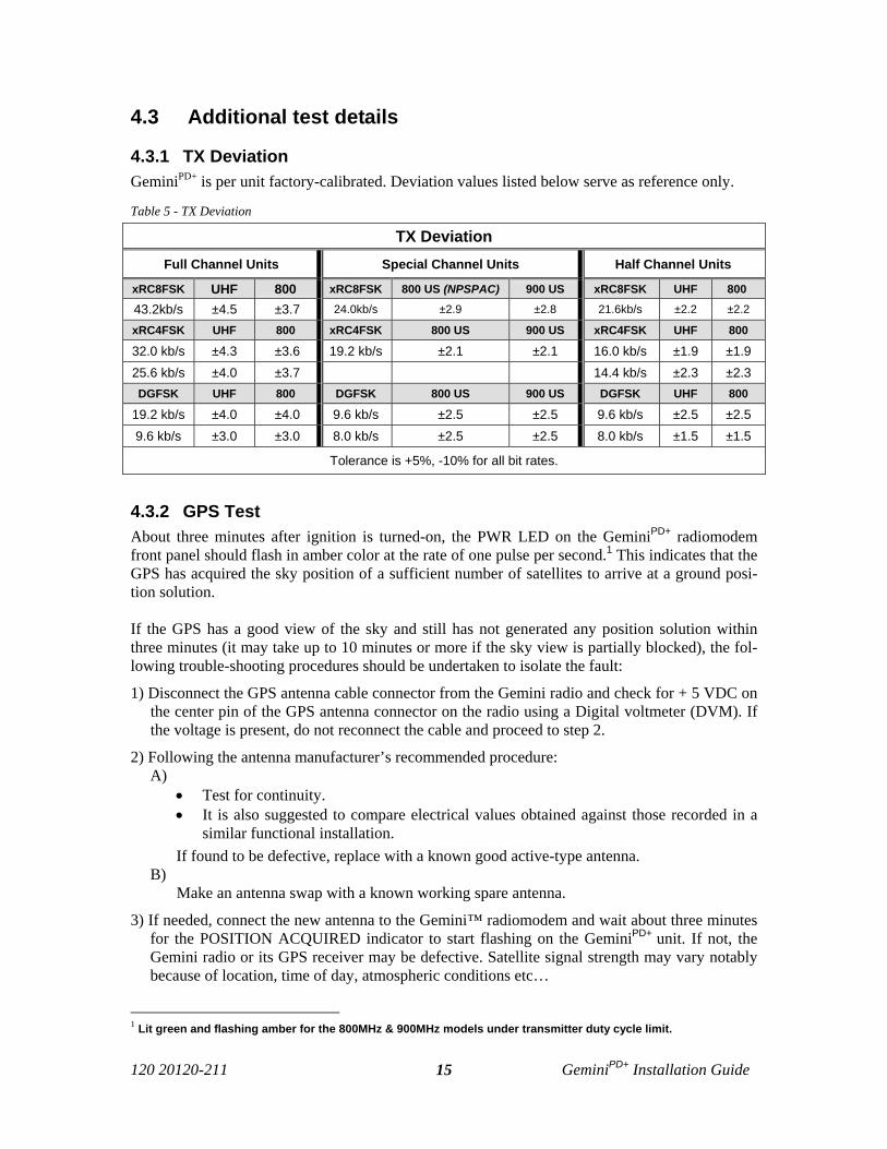
4.3.1 TX DeviationGeminiPD+ is per unit factory-calibrated. Deviation values listed below serve as reference only.
Table 5 - TX Deviation
TX DeviationFull Channel Units Special Channel Units Half Channel Units
xRC8FSK UHF 800 xRC8FSK 800 US (NPSPAC) 900 US xRC8FSK UHF 800
43.2kb/s ±4.5 ±3.7 24.0kb/s ±2.9 ±2.8 21.6kb/s ±2.2 ±2.2
xRC4FSK UHF 800 xRC4FSK 800 US 900 US xRC4FSK UHF 800
32.0 kb/s ±4.3 ±3.6 19.2 kb/s ±2.1 ±2.1 16.0 kb/s ±1.9 ±1.925.6 kb/s ±4.0 ±3.7 14.4 kb/s ±2.3 ±2.3DGFSK UHF 800 DGFSK 800 US 900 US DGFSK UHF 800
19.2 kb/s ±4.0 ±4.0 9.6 kb/s ±2.5 ±2.5 9.6 kb/s ±2.5 ±2.59.6 kb/s ±3.0 ±3.0 8.0 kb/s ±2.5 ±2.5 8.0 kb/s ±1.5 ±1.5
Tolerance is +5%, -10% for all bit rates.
4.3.2 GPS TestAbout three minutes after ignition is turned-on, the PWR LED on the GeminiPD+ radiomodemfront panel should flash in amber color at the rate of one pulse per second.1 This indicates that theGPS has acquired the sky position of a sufficient number of satellites to arrive at a ground posi-tion solution.
If the GPS has a good view of the sky and still has not generated any position solution withinthree minutes (it may take up to 10 minutes or more if the sky view is partially blocked), the fol-lowing trouble-shooting procedures should be undertaken to isolate the fault:
1) Disconnect the GPS antenna cable connector from the Gemini radio and check for + 5 VDC onthe center pin of the GPS antenna connector on the radio using a Digital voltmeter (DVM). Ifthe voltage is present, do not reconnect the cable and proceed to step 2.
2) Following the antenna manufacturer’s recommended procedure:A)
• Test for continuity. • It is also suggested to compare electrical values obtained against those recorded in a
similar functional installation. If found to be defective, replace with a known good active-type antenna.
B) Make an antenna swap with a known working spare antenna.
3) If needed, connect the new antenna to the Gemini™ radiomodem and wait about three minutesfor the POSITION ACQUIRED indicator to start flashing on the GeminiPD+ unit. If not, theGemini radio or its GPS receiver may be defective. Satellite signal strength may vary notablybecause of location, time of day, atmospheric conditions etc…
1 Lit green and flashing amber for the 800MHz & 900MHz models under transmitter duty cycle limit.
120 20120-211 GeminiPD+ Installation Guide16
4.3.3 RF Data Link Test A link test between a mobile and a known base station can be done using the WinRIS "Address"and "Send" functions. The “Address” and “Device” fields, the “Send” button and the “Chat” mes-sage screen are used to send messages to specific mobile or base or to carry out RF test. Start byentering the address of the mobile (or base station) you wish to send a test message to or test:
1- Specify the address:Addresses may be entered by typing directly in the “Address” field in two ways:- Numerically, the valid address range is 1-126.- As an “Alpha-Mapped-Nibble” (AMN) address, consisting of upper case letters in the
range A-P. The valid address range is A to GN.- The base address is usually: 1.- The program may display one of the following messages on the status bar:- For Paragon products:
“address is not in AMN or number format”- For mobile products:
“address is not in the range A – GN”In either case, check that the address entered is within the acceptable range, is of a valid for-mat, and correctly typed.
2- Enter the Device number for mobile (or base station).3- Press the Send button.
The Chat window reports “Sent to xx mobile” (where xx is mobile name).
If test is successful:Status line reports “Delivery confirmed.
If test unsuccessful: Chat window reports “Waiting”, Then the Status line reports “Delivery Failed”.
120 20120-211 GeminiPD+ Installation Guide17
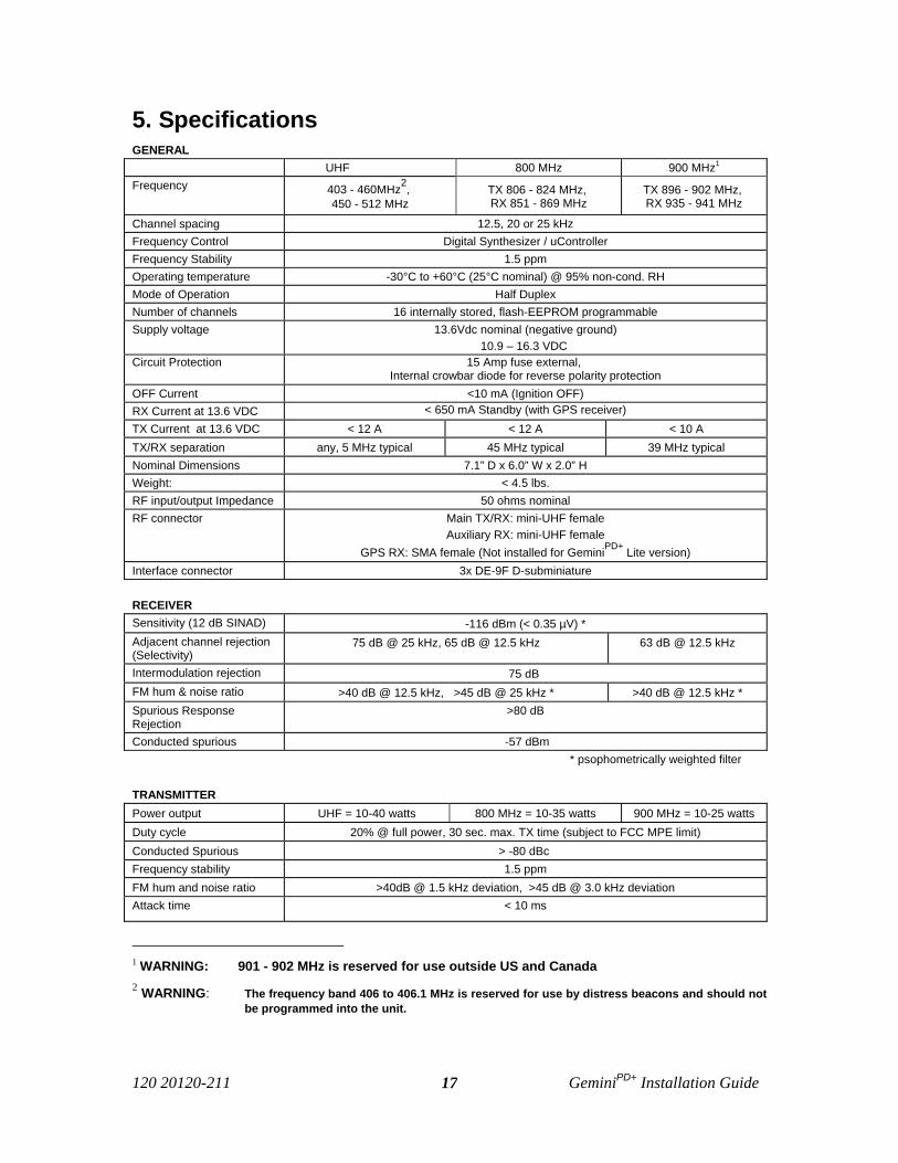
5. SpecificationsGENERAL
UHF 800 MHz 900 MHz1
Frequency 403 - 460MHz2, 450 - 512 MHz
TX 806 - 824 MHz, RX 851 - 869 MHz
TX 896 - 902 MHz, RX 935 - 941 MHz
Channel spacing 12.5, 20 or 25 kHzFrequency Control Digital Synthesizer / uControllerFrequency Stability 1.5 ppmOperating temperature -30°C to +60°C (25°C nominal) @ 95% non-cond. RHMode of Operation Half DuplexNumber of channels 16 internally stored, flash-EEPROM programmableSupply voltage 13.6Vdc nominal (negative ground)
10.9 – 16.3 VDC Circuit Protection 15 Amp fuse external,
Internal crowbar diode for reverse polarity protectionOFF Current <10 mA (Ignition OFF)RX Current at 13.6 VDC < 650 mA Standby (with GPS receiver)TX Current at 13.6 VDC < 12 A < 12 A < 10 ATX/RX separation any, 5 MHz typical 45 MHz typical 39 MHz typicalNominal Dimensions 7.1” D x 6.0” W x 2.0” HWeight: < 4.5 lbs.RF input/output Impedance 50 ohms nominalRF connector Main TX/RX: mini-UHF female
Auxiliary RX: mini-UHF femaleGPS RX: SMA female (Not installed for GeminiPD+ Lite version)
Interface connector 3x DE-9F D-subminiature
RECEIVERSensitivity (12 dB SINAD) -116 dBm (< 0.35 µV) *Adjacent channel rejection(Selectivity)
75 dB @ 25 kHz, 65 dB @ 12.5 kHz 63 dB @ 12.5 kHz
Intermodulation rejection 75 dB FM hum & noise ratio >40 dB @ 12.5 kHz, >45 dB @ 25 kHz * >40 dB @ 12.5 kHz *Spurious ResponseRejection
>80 dB
Conducted spurious -57 dBm* psophometrically weighted filter
TRANSMITTERPower output UHF = 10-40 watts 800 MHz = 10-35 watts 900 MHz = 10-25 wattsDuty cycle 20% @ full power, 30 sec. max. TX time (subject to FCC MPE limit)Conducted Spurious > -80 dBc Frequency stability 1.5 ppmFM hum and noise ratio >40dB @ 1.5 kHz deviation, >45 dB @ 3.0 kHz deviationAttack time < 10 ms
1 WARNING: 901 - 902 MHz is reserved for use outside US and Canada2 WARNING: The frequency band 406 to 406.1 MHz is reserved for use by distress beacons and should not
be programmed into the unit.
120 20120-211 GeminiPD+ Installation Guide18
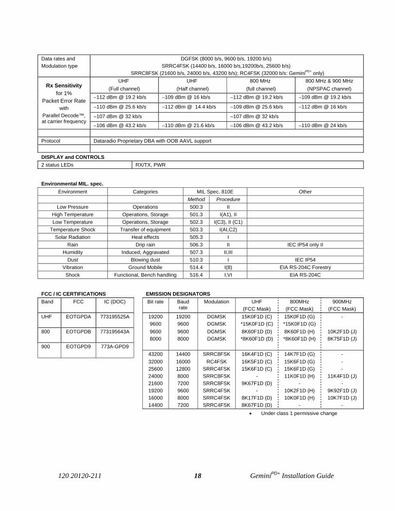
Data rates andModulation type
DGFSK (8000 b/s, 9600 b/s, 19200 b/s) SRRC4FSK (14400 b/s, 16000 b/s,19200b/s, 25600 b/s)
SRRC8FSK (21600 b/s, 24000 b/s, 43200 b/s); RC4FSK (32000 b/s: GeminiPD+ only)UHF
(Full channel)UHF
(Half channel)800 MHz
(full channel)800 MHz & 900 MHz(NPSPAC channel)
–112 dBm @ 19.2 kb/s –109 dBm @ 16 kb/s –112 dBm @ 19.2 kb/s –109 dBm @ 19.2 kb/s
–110 dBm @ 25.6 kb/s –112 dBm @ 14.4 kb/s –109 dBm @ 25.6 kb/s –112 dBm @ 16 kb/s
–107 dBm @ 32 kb/s –107 dBm @ 32 kb/s
Rx Sensitivityfor 1%
Packet Error Rate with
Parallel Decode™,at carrier frequency
–106 dBm @ 43.2 kb/s –110 dBm @ 21.6 kb/s –106 dBm @ 43.2 kb/s –110 dBm @ 24 kb/s
Protocol Dataradio Proprietary DBA with OOB AAVL support
DISPLAY and CONTROLS2 status LEDs RX/TX, PWR
Environmental MIL. spec.Environment Categories MIL Spec. 810E Other
Method ProcedureLow Pressure Operations 500.3 II
High Temperature Operations, Storage 501.3 I(A1), IILow Temperature Operations, Storage 502.3 I(C3), II (C1)
Temperature Shock Transfer of equipment 503.3 I(AI,C2)Solar Radiation Heat effects 505.3 I
Rain Drip rain 506.3 II IEC IP54 only IIHumidity Induced, Aggravated 507.3 II,III
Dust Blowing dust 510.3 I IEC IP54Vibration Ground Mobile 514.4 I(8) EIA RS-204C Forestry
Shock Functional, Bench handling 516.4 I,VI EIA RS-204C
FCC / IC CERTIFICATIONS EMISSION DESIGNATORSBand FCC IC (DOC) Bit rate Baud
rateModulation UHF
(FCC Mask)800MHz
(FCC Mask)900MHz
(FCC Mask)UHF EOTGPDA 773195525A 19200 19200 DGMSK 15K0F1D (C) 15K0F1D (G) -
9600 9600 DGMSK *15K0F1D (C) *15K0F1D (G)800 EOTGPDB 773195643A 9600 9600 DGMSK 8K60F1D (D) 8K60F1D (H) 10K2F1D (J)
8000 8000 DGMSK *8K60F1D (D) *8K60F1D (H) 8K75F1D (J)900 EOTGPD9 773A-GPD9
43200 14400 SRRC8FSK 16K4F1D (C) 14K7F1D (G) -32000 16000 RC4FSK 16K5F1D (C) 15K6F1D (G) -25600 12800 SRRC4FSK 15K6F1D (C) 15K6F1D (G) -24000 8000 SRRC8FSK - 11K0F1D (H) 11K4F1D (J)21600 7200 SRRC8FSK 9K67F1D (D) - -19200 9600 SRRC4FSK - 10K2F1D (H) 9K92F1D (J)16000 8000 SRRC4FSK 8K17F1D (D) 10K0F1D (H) 10K7F1D (J)14400 7200 SRRC4FSK 8K67F1D (D) - -
• Under class 1 permissive change
120 20120-211 GeminiPD+ Installation Guide19
Appendix 1 - "Officer Requires Assistance" alarm function
The contents of this appendix are also available as Technical Instruction Sheet 009 (TIS009),document part number 122 20110-009 dated December 20, 2000.
OverviewThe DTE Port Interface pin 9 (AUX) on DEV-2 is used for the “Officer Requires Assistance”alarm function.
Intended AudienceThis document is designed for use by System Integrators.
Physical ConnectionThis auxiliary input may be activated by (normally open) dry contact pull-up to the port’s DSRoutput. It can also tolerate user pull-up to external +12 VDC (car battery), but an isolated drycontact is preferred due to the risk of noise-related false alarms caused by the vehicle’s electricalsystem.A +3 to +12 V signal at this pin will send a DMP “x” (On) message to the base. An open or ground signal will send a DMP “y” (Off) message.Messages are only sent when a signal transition occurs (debounced for approximately 100 ms).
OperationWhen using GeminiPD+ or GeminiPD+ Lite products, activating the “Officer Requires Assistance”alarm input starts emergency communications:
• The modem creates DMP “x” or “y” messages.• Any other pending message(s) will be failed to avoid delaying the alarm message on
account of lower priority traffic and to remove non-emergency messages from duty-cycle management (if applicable). In the case of a “q” message, a D-NAK* will beimmediately returned.
• Base and Channel hunt will take place for the usual number of retries per base (ac-cording to configuration) but will cycle forever until D-ACKed1 or Reset1.
• Lack of base DBA synch will not prevent transmission to maximize the chance that abase gets the alarm signal. DBA “Freewheel” mode will be forced until the alarm isacknowledged.
1 For details on DMP terms, refer to DMP 1.5 manual, version 4.0 or later
120 20120-211 GeminiPD+ Installation Guide20
Appendix 2 – Special Application – Carrier Sense (CS-DBA)
Intended for use in communication systems where data-customers must share channels with oneor more voice-customer(s). Refer to Dataradio’s System Engineering for details. The CarrierSense feature is usually factory-set at time of order.
Normal setup for “voice” transmissions:
• Half-duplex – Transmit and Receive is done on the same frequency as “data” transmissions.• Voice repeater (base) – In dispatch systems, when base-originated voice transmissions take
place, all mobiles hear the voice message. Mobiles do not talk to each other directly.
Operation:
If mobile voice-transmits, the voice repeater base often puts up sub-audible tones, called “busytone” as an indication that the voice channel is in-use. Data-mobiles are already listening on therepeater frequency. For the data-base station to be able to determine that a voice channel is in-userequires the use of a “guard-receiver” listening to the voice repeater. This component is added tothe base rack.
On Carrier Sense-enabled systems, operations are on a “first-come, first-served” basis. If thechannel is voice-busy, data communications from base and mobiles are expected to wait until on-going voice communication completes before keying up. Similarly, voice communication frombase and mobile systems are expected to check first if channel is data-busy. If it is, then voicemust wait for the data carrier to go away. Brief periods of voice communications should be in-visible to customer applications. Long periods of voice (or interference) will delay delivery-confirmation responses from the radio-modem and the application may timeout and resend itsdata. In multi-tower systems, the use of long voice-messaging may not be recommended.
To help data-applications coexist with voice-applications, the option of having the Carrier Sensestatus reflected on the DCD lead conveys the “channel is busy with voice” information to the ap-plication so it can be made to suspend its own timeout timers. System Engineering will arrangefor this option to be set on user equipment where applicable. If enabled, toggling of DCD mayaffect application’s DMP driver if it expects DCD to remain normally active. Therefore, softwarevendors may have to write or upgrade their software so that the DMP driver expects DCD to tog-gle often and to make use of the information that DCD is conveying.
DATARADIO is a registered trademark, Gemini, Gemini PD, and PARALLEL DECODE are trademarksof Dataradio Inc