mobile service and start-up set for the technolink radio ... · mobile service and start-up set for...
TRANSCRIPT

Technical data sheet 5.60-10.001-01-en
Description of the set TriCorder
TriCorder Mobile service and start-up set for the technoLink radio-communication system
Contents Description of the set Page 2 Safety instructions Page 2 Qualified specialists Page 2 Application Page 3 Technical data Page 3 Structure Page 4 Function tree Page 6 General instructions Page 7 Function description Page 9 Call of a function Page 9 ‘Drive training’ function Page 10 Logbook function Page 12 Simulation function Page 12 Load solar radio-communication function Page 14 Scan addresses function Page 15 Memory function Page 17 Contrast function Page 17 Coverage test function Page 18 General information about radio signal transmission Page 19 Function of the test transmitters Page 20
Kieback & Peter GmbH & Co KG Tempelhofer Weg 50, D-12347 Berlin Telephone +49 (0) 30 / 600 95-0 Telefax +49 (0) 30 / 600 95 164 E-Mail: [email protected] http://www.kieback-peter.de
Dat
e of
Issu
e: 4
/18/
2005
C
onte
nts
subj
ect t
o ch
ange

Technical data sheet 5.60-10.001-01-en
TriCorder Description of the set
Description of the set The description includes information about the use of the mobile service and diagnosis set "TriCorder" as well as the associated test transmitter. In case of questions, which cannot be clarified in this description, please contact the supplier or manufacturer for further information. The operating staff has to be trained as described in the technical data sheet.
Safety instructions Make sure that the set is always switched off when it is not in use (e.g. transport, delivery). Service and starting operations with the TriCorder are to be carried out by qualified staff only, see section "Quali-fied staff". Every person who uses the set shall have read and understood the descriptions in the technical data sheet prior to using it. Meaning of the symbols used in the technical data sheet:
General warning, strictly observe this notice
Warning
Additional note to be observed
Note Warning Means danger of physical injuries or material damage in case of non-observance. Note Indicates information particularly emphasized
Qualified specialists Qualified specialists for the purposes set out in this technical data sheet are persons who are familiar with the described set and have a respective qualification in their occupation. The following requirements have to be observed by them: • Authorization for switching on, switching off and releasing the sets in compliance with intra-company rules. • Knowledge of the use of these sets within the plant system. • etc.
Page 2 / 22

Technical data sheet 5.60-10.001-01-en
Description of the set TriCorder
Application Mobile service and start-up set for planning, testing, starting, simulation of system components of the technoLink radio-communication system. Its typical functions, such as coverage test, training, simulation, or address scanning make the TriCorder a highly efficient tool in handling the radio-communication system technoLink. A test transmitter has been included in each set and forms a separate component so that it is possible to carry out coverage tests and installation environment evaluations, respectively. Special knowledge is not required to operate and use the TriCorder.
The set is operated interactively with the 8-line-display and keyboard. Based on the menu procedure, the operator is guided through the function tree. Various functions can be enabled and executed in the sub-menus.
Operational environment
Note
When the set is used in an environment subject to high electromagnetic disturbances such as in the typical industrial environment, there might be problems with interference to the product.
Type TriCorder Mobile service and start-up set for the technoLink radio-communication
system
Technical data Operating voltage 4xAA batteries / power pack 4..9V DC Frequency 868.35 MHz Ambient temperature 0..45°C Enclosure ABS, color: agate gray Degree of enclosure protection
IP30
Dimensions Width x height x depth = 110 x 204 x 41 mm
Scope of delivery 1 TriCorder 1 test transmitter 1 update cable 1 solar radio loading cable 1 carrier bag
Page 3 / 22

Technical data sheet 5.60-10.001-01-en
TriCorder Description of the set
Structure
Top cover
Display
START – key
F1 – to F10 – key
Arrow – keys
ENTER – key
SPACE – key
Battery cover
Cap for mains plug
Switching on/off
The set is switched on when the START-key is pressed. The current software version of the TriCorder is then displayed for 2 s.
1.05
Page 4 / 22

Technical data sheet 5.60-10.001-01-en
Description of the set TriCorder
Thereafter, the main menu appears on the display . Main menu
TriCorder
> Initial operation
Radio diagnosis Bus diagnosis Update System F1=HLP F5=OFF
You can execute the individual operations now (see function tree). The TriCorder is switched off when the F5- key is pressed.
If the key is not depressed within 15 minutes, the set is automatically switched off.
Note
This automatic switching-off can be deactivated in the menu position System/Adjustments/Operating Mode.
Page 5 / 22
Technical data sheet 5.60-10.001-01-en
TriCorder Description of the set
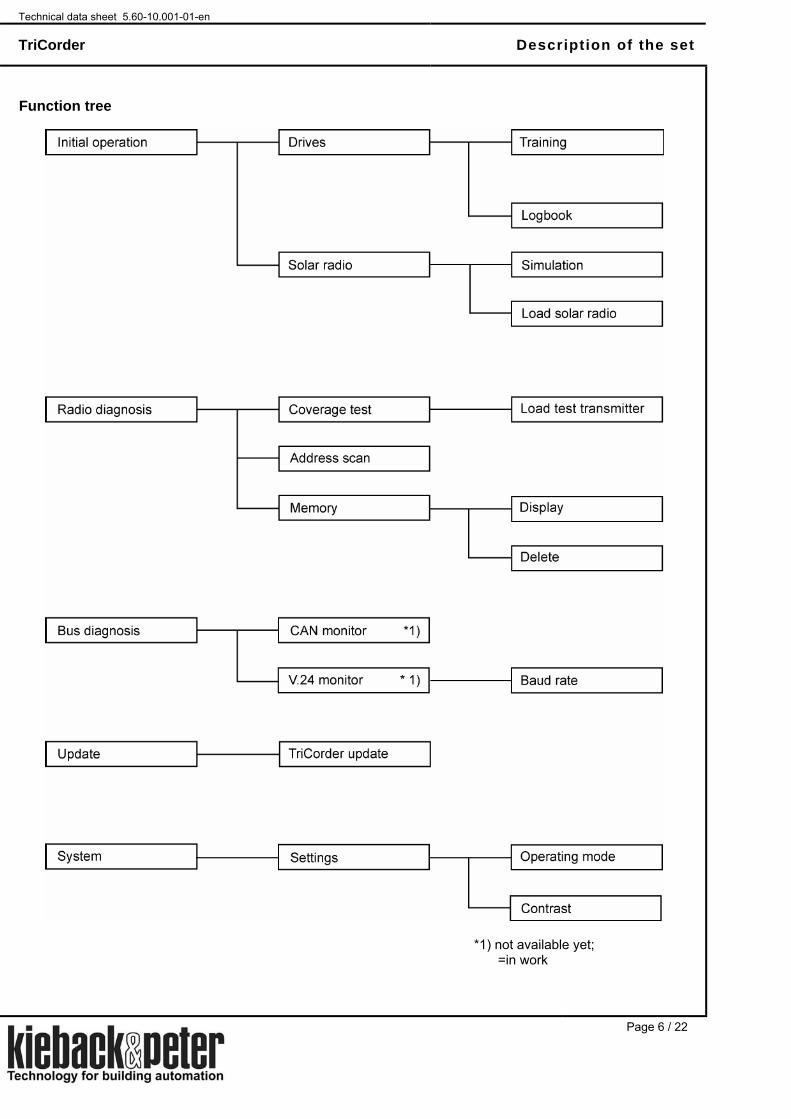
Function tree
*1) not available yet; =in work
Page 6 / 22

Technical data sheet 5.60-10.001-01-en
Description of the set TriCorder
General instructions Battery change If switching-on/off is not possible or the display fades change batteries.
1
Depress the unlatching buttons arranged at the side in the lower area of the set and remove battery cover .
2
Pull off connection of battery tray and take out the battery tray.
3
Take out old batteries and insert new ones according to the information about polarity.
4 Insert battery tray and make connection . 5 Snap on battery tray again.
Note
Use only leak-proof 1.5 V alkaline-batteries of the size AA or respective, commercially available 1.2 V accumulators. Charging of the accumulators is not possible through the 4.9 V- socket .
When batteries are changed, replace all 4 batteries. Make sure that the poles are correct when inserting new batteries. Use always 4 identical batteries of the same manufacturer and type.
Do not throw used batteries into the household refuse, but bring them to local battery collection sites for free-of-charge disposal.
Warning
Power supply Alternatively to battery operation, the service- and start-up tool may also be fed from a suitable power supply unit (4..10V DC, ≥200 mA).
1 Remove cap from lower battery cover . 2 Put the mains plug into the 4..9 V socket below it.
Page 7 / 22

Technical data sheet 5.60-10.001-01-en
TriCorder Description of the set
TriCorder update New software versions can be loaded via the serial interface of a PC. First of all, load the update-software on a PC.
1
Depress unlatching buttons arranged at the side in the upper area of the set and remove upper cover . Behind the cover, there is interface (9-pole-jack) for loading an update.
2
Afterwards, connect the TriCorder via the update cable included in the scope of delivery with the PC (Com1).
3 Update mode at the TriCorder via path: Activate Update/Tricorder Update with acknowledgement
of the start-key. 4
Start the file "Run_Me.bat" of the update-software. Afterwards, follow the monitor dialog on the PC.
5
After updating has been completed, disconnect the cable connection to the computer and snap on the upper cover again.
Note
The file “liesmich.txt“, which is part of the update-software, includes a detailed operational sequence description of the software update.
Page 8 / 22

Technical data sheet 5.60-10.001-01-en
Description of the set TriCorder
Function description General
Call of a function Select the desired function from the menu with arrow keys and acknowledge with the Enter key. Using the Space key, one input step is returned or the function is interrupted. Direct help is called with the F1 key.
Example: Simulation
TriCorder
> Initial operation
Radio diagnosis Dial the function Start-up with the arrow keys < > < > .
Bus diagnosis Update <ENTER>
System F1=HLP F5=OFF
Initial operation
Drives > Solar radio
Dial the function Solar radio with the arrow keys < > < >.
<ENTER>
F1=HLP F5=OFF
Solar radio
> Simulation Charge solar radio
Dial the function Simulation with the arrow keys < > < >.
<ENTER>
F1=HLP F5=OFF
Simulation/
> 0..100% °C
F1=HLP F5=OFF
You are now in the function Simulation, which is described in detail in the Simulation section.
Page 9 / 22
Technical data sheet 5.60-10.001-01-en
TriCorder Description of the set
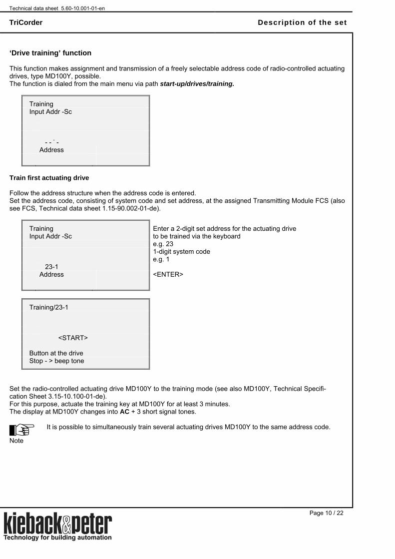
‘Drive training’ function This function makes assignment and transmission of a freely selectable address code of radio-controlled actuating drives, type MD100Y, possible. The function is dialed from the main menu via path start-up/drives/training.
Training
Input Addr -Sc
- - - - Address
Train first actuating drive Follow the address structure when the address code is entered. Set the address code, consisting of system code and set address, at the assigned Transmitting Module FCS (also see FCS, Technical data sheet 1.15-90.002-01-de).
Training Input Addr -Sc
Enter a 2-digit set address for the actuating drive to be trained via the keyboard
e.g. 23 1-digit system code e.g. 1 23-1 Address <ENTER>
Training/23-1
<START>
Button at the drive Stop - > beep tone
Set the radio-controlled actuating drive MD100Y to the training mode (see also MD100Y, Technical Specifi-cation Sheet 3.15-10.100-01-de). For this purpose, actuate the training key at MD100Y for at least 3 minutes. The display at MD100Y changes into AC + 3 short signal tones.
Note
It is possible to simultaneously train several actuating drives MD100Y to the same address code.
Page 10 / 22
Technical data sheet 5.60-10.001-01-en
Description of the set TriCorder
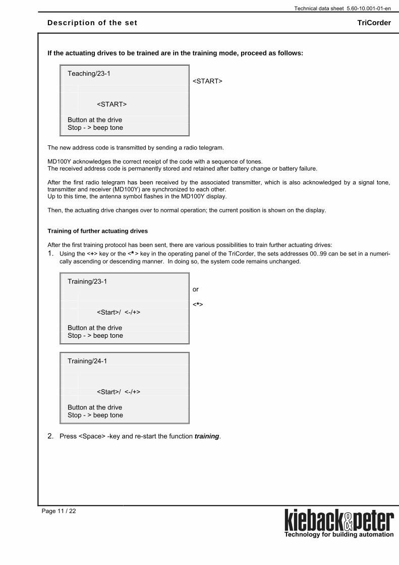
If the actuating drives to be trained are in the training mode, proceed as follows:
Teaching/23-1 <START>
<START>
Button at the drive Stop - > beep tone
The new address code is transmitted by sending a radio telegram. MD100Y acknowledges the correct receipt of the code with a sequence of tones. The received address code is permanently stored and retained after battery change or battery failure. After the first radio telegram has been received by the associated transmitter, which is also acknowledged by a signal tone, transmitter and receiver (MD100Y) are synchronized to each other. Up to this time, the antenna symbol flashes in the MD100Y display. Then, the actuating drive changes over to normal operation; the current position is shown on the display. Training of further actuating drives After the first training protocol has been sent, there are various possibilities to train further actuating drives: 1. Using the <+> key or the <*> key in the operating panel of the TriCorder, the sets addresses 00..99 can be set in a numeri-
cally ascending or descending manner. In doing so, the system code remains unchanged.
Training/23-1 or
<Start>/ <-/+>
<*>
Button at the drive Stop - > beep tone
Training/24-1
<Start>/ <-/+>
Button at the drive Stop - > beep tone
2. Press <Space> -key and re-start the function training.
Page 11 / 22

Technical data sheet 5.60-10.001-01-en
TriCorder
Logbook function This function writes down all operating actions, which have been carried out using the function training. It is dialed from the main menu via path start-up/drives/logbook.
Logbook
03:40 Add.25-1 02:01 Add.02-2 01:47 Add.01-6 01:36 Add.12-3
The displayed time states the point when training was executed after the TriCorder was switched on.
The logbook is automatically deleted when the TriCorder is switched off.
Warning
Simulation function This function makes it possible that 0..10 V- or KP10-radio telegrams can be sent for functional testing of receivers. Thus, the TriCorder takes over the function of a transmitter in a radio link that is to be tested. The function is dialed from the main menu via path start-up/solar-radio/simulation.
Simulation/
> 0..100% °C
Select the desired radio telegram with the arrow keys < > < >.
<ENTER>
Training
Input Addr -Sc
- - - - Address
Page 12 / 22

Technical data sheet 5.60-10.001-01-en
Description of the set TriCorder
Simulation/ Input Addr -Sc
Enter the 3-digit address code of the receiver to be tested via the keyboard.
<1> <2> 12-3 <3> Address <ENTER>
Simulation/A12-3 35
Enter the simulating value via the keyboard.
<3> Value <5> <ENTER>
Simulation/A12-3/ 35% <START>
<START>
A radio telegram with an analogous value 35% is now transmitted with the address 12-3.
Due to MD100Y’s cyclic mode of operation, a forced control of the TriCorder in regular operation is not possible.
Warning
Page 13 / 22

Technical data sheet 5.60-10.001-01-en
TriCorder Description of the set
Load solar radio-communication function This function makes it possible to quickly load an initial start-up from a solar radio room probe of the internal en-ergy store. After loading has been successful, the solar radio room probe is ready for operation and can immediately be used.
1
Depress the unlatching buttons arranged at the side in the upper area of the set and remove upper cover . Behind the cover, there is interface (9-pole-jack) for the solar radio loading cable.
2
Afterwards, connect the TriCorder with the solar radio room probe (e.g. TCF12) via the solar radio loading cable .
3
Switch on the TriCorder and dial the function via path start-up/solar radio/solar radio loading.
4 Start the loading procedure by pressing the Enter key.
The end of a loading procedure is acknowl-edged by a signal tone.
Note
Load solar radio Loading finished Pull off the plug
This message ap-pears in the TriCorder display
5 Switch off the TriCorder.
Loosen cable connection and snap on upper cover again.
Page 14 / 22
Technical data sheet 5.60-10.001-01-en
Description of the set TriCorder
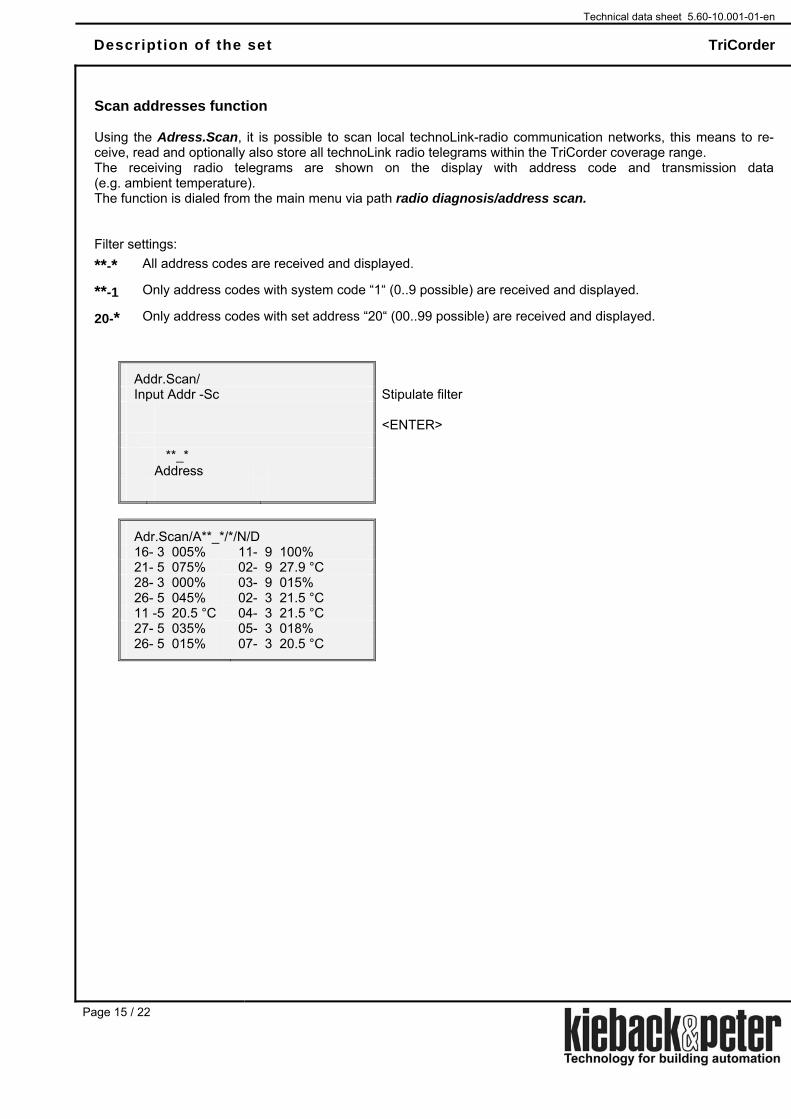
Scan addresses function Using the Adress.Scan, it is possible to scan local technoLink-radio communication networks, this means to re-ceive, read and optionally also store all technoLink radio telegrams within the TriCorder coverage range. The receiving radio telegrams are shown on the display with address code and transmission data (e.g. ambient temperature). The function is dialed from the main menu via path radio diagnosis/address scan. Filter settings: **-* All address codes are received and displayed.
**-1 Only address codes with system code “1“ (0..9 possible) are received and displayed.
20-* Only address codes with set address “20“ (00..99 possible) are received and displayed.
Addr.Scan/ Input Addr -Sc Stipulate filter
<ENTER> **_* Address
Adr.Scan/A**_*/*/N/D 16- 3 005% 11- 9 100% 21- 5 075% 02- 9 27.9 °C 28- 3 000% 03- 9 015% 26- 5 045% 02- 3 21.5 °C 11 -5 20.5 °C 04- 3 21.5 °C 27- 5 035% 05- 3 018% 26- 5 015% 07- 3 20.5 °C
Page 15 / 22

Technical data sheet 5.60-10.001-01-en
TriCorder Description of the set
Additional functions can be activated in order to effectively use the function Addresses Scan:
Key Additional function Indicate first display line <F2> Switch-over to gain-to-noise-temperature ratio
Normal (= set standard “technoLink“) Addr.Scan/A**- */*/N/D
Superhet (= higher sensitivity) Addr.Scan/A**- */*/S
<F3> Selection of the radio telegram to be received
All Addr.Scan/A**- */*/N
KP10 Addr.Scan/A**- */°C/N
0..10 V DC Addr.Scan/A**- */%/N
Switching commands (not activated yet) Addr.Scan/A**- */S/N
<F4> Memory
On Addr.Scan/A**- */*/N/D
Off Addr.Scan/A**- */*/N
<*> Delete memory
<+> Delete display
<8> Sorting of the received data according to address in ascending order
<2> Sorting of the received data according to address in descend-ing order
Note
The technoLink sets have been designed for the gain-to-noise-temperature ratio “Normal“.
Page 16 / 22

Technical data sheet 5.60-10.001-01-en
Description of the set TriCorder
Memory function In the memory, all data, which were received with the function Adress.Scan, are stored. For this purpose, the addi-tional function “Write memory” must be active in the function Adress.Scan (<F4>- key). The memory is displayed from the main menu via path radio/diagnosis/memory.
Memory
> Display Delete
Select the display function with the arrow keys < > < >.
<ENTER>
Memory 00:08 16- 5 024% 00:02 19- 3 058% 00:04 17- 3 052% 00:06 08- 2 058% 00:12 19- 3 23.7°C 00:02 08- 3 058% 00:14 02- 3 21.3°C
All recorded data are shown on the display. The displayed time is always the time passed between receiving and preceding radio telegram. Approx. 224 data are stored in the memory. The content of the memory is maintained even after the TriCorder has been switched off. Contrast function This function adjusts contrasts. It is dialed from the main menu via path system/settings/contrast.
Contrast <-7->
Select the desired contrast using the arrow keys < > < >.
Page 17 / 22
Technical data sheet 5.60-10.001-01-en
TriCorder Description of the set
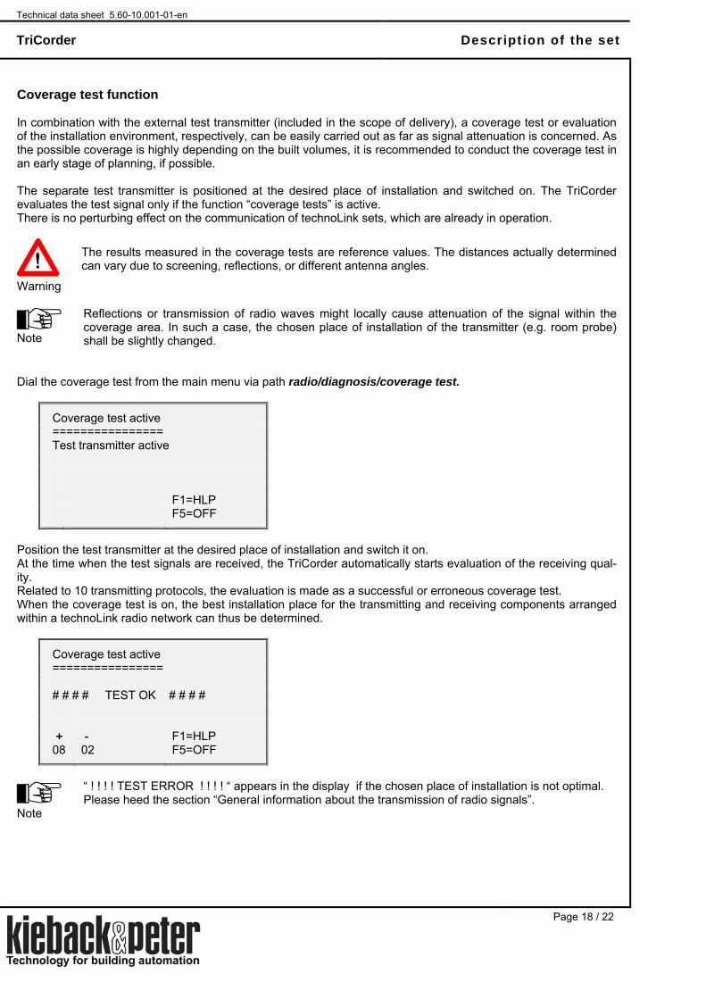
Coverage test function In combination with the external test transmitter (included in the scope of delivery), a coverage test or evaluation of the installation environment, respectively, can be easily carried out as far as signal attenuation is concerned. As the possible coverage is highly depending on the built volumes, it is recommended to conduct the coverage test in an early stage of planning, if possible. The separate test transmitter is positioned at the desired place of installation and switched on. The TriCorder evaluates the test signal only if the function “coverage tests” is active. There is no perturbing effect on the communication of technoLink sets, which are already in operation.
The results measured in the coverage tests are reference values. The distances actually determined can vary due to screening, reflections, or different antenna angles.
Warning
Note
Reflections or transmission of radio waves might locally cause attenuation of the signal within the coverage area. In such a case, the chosen place of installation of the transmitter (e.g. room probe) shall be slightly changed.
Dial the coverage test from the main menu via path radio/diagnosis/coverage test.
Coverage test active
================ Test transmitter active
F1=HLP F5=OFF
Position the test transmitter at the desired place of installation and switch it on. At the time when the test signals are received, the TriCorder automatically starts evaluation of the receiving qual-ity. Related to 10 transmitting protocols, the evaluation is made as a successful or erroneous coverage test. When the coverage test is on, the best installation place for the transmitting and receiving components arranged within a technoLink radio network can thus be determined.
Coverage test active
================ # # # # TEST OK # # # #
+ - F1=HLP 08 02 F5=OFF
“ ! ! ! ! TEST ERROR ! ! ! ! “ appears in the display if the chosen place of installation is not optimal.
Please heed the section “General information about the transmission of radio signals”. Note
Page 18 / 22

Technical data sheet 5.60-10.001-01-en
Description of the set TriCorder
General information about radio signal transmission
The radio signals are electromagnetic waves so that the signal is attenuated on the way to the receiver. The electri-cal and magnetic field intensity decreases proportionally to the square of the distance between transmitter and receiver. Attenuation
Radio waves can penetrate walls. Contrary to the coverage on the free field, the signal is subject to a more or less high attenuation when it penetrates solid bodies. Attenuation of various materials
Material Material thickness Attenuation Wood < 30 cm approx. 10% Gypsum plaster boards < 10 cm approx. 10% Glass (without metal coating or wire layer) < 5 cm approx. 10% Gas concrete block < 30 cm approx. 20% Brick < 30 cm approx. 35% Iron-reinforced concrete < 30 cm approx. 30% - 90% Ceiling < 30 cm approx. 70% Outer wall < 30 cm approx. 60% Inner wall < 30 cm approx. 40% Metal grille (e.g. wire cloth plaster) < 1 mm approx. 90% Metals, aluminum lamination < 1mm up to 100%
This means that the construction materials used in a building play a significant role in the achievable radio cover-age. Restrictions of transmission
In practical application, there are also outside interferences in addition to the natural restriction of coverage. These are metallic parts, which reflect electromagnetic waves. Behind these parts, a so-called radio shadow is formed. (Reinforcements in walls, metal foils of heat insulations, metallic heat protection glass, etc.)
Page 19 / 22

Technical data sheet 5.60-10.001-01-en
TriCorder Description of the set
Wall thickness
Moreover, the angle at which the signal strikes the wall plays a certain role. In dependence on the angle, the effective wall thickness and thus attenuation of the signal change. Signals should run vertically through the walling and avoid bays.
Sources of interference
Devices that also work with high-frequency signals, such as computers, audio-/video systems, comfort tele-phones, electrical transformers, and chokes are also sources of interference during radio transmission. The minimum distance to these devices should come to 0.50 m. The coverage will be massively reduced if the set is positioned on metallic surfaces.
Function of the test transmitters
Set on/off
Selection of the mode of operation
Transmitting-LED
Battery case 2 x AAA 1.5 V
Front Back
DIP-switch on/off
The set is switched on/off by pressing the lower DIP-switch (0: set OFF, I: set ON). After that, the test signal transmission starts after a turn-on delay of three seconds. Each signal, which has been sent, is displayed by a short flashing of the transmitting LED .
Do not hold the set in your hand when the test signal is transmitted, otherwise the measured results might be falsified.
Warning
Page 20 / 22
Technical data sheet 5.60-10.001-01-en
Description of the set TriCorder
DIP-switch mode of operation Mode of operation 1 ( I I I ):
In mode of operation 1, a test signal is transmitted every three seconds. When the set is exclusively operated in mode 1, it is automatically switched off after 60 minutes (low-energy mode) so that unintended continuous op-eration is avoided.
Mode of operation 2 (IIIII ): In mode of operation 2, a test signal is transmitted every second. When the set is exclusively operated in mode 2, it is automatically switched off after 20 minutes.
Principally, it is possible to change the operating mode in continuous operation. When changing over from operat-ing mode 2 to 1, the maximum running time is prolonged due to longer interval times between the transmissions. In reverse, i.e. when changing from operating mode 1 to 2, the maximum running time is shortened and thus leads to an earlier automatic switching-off of the set.
Due to the Duty Cycle-Stipulation for the 868 MHz band, the set can be operated within 60 minutes in the operating mode 1 as long as the operator likes. As far as operating mode 2 is concerned, it may only be operated for a period of max. 20 minutes.
Warning If operating mode 2 is used in the switched-on state, the set may only be switched on again after one hour after beginning of transmission has passed.
The operator of the set has to make sure that these conditions are observed.
Page 21 / 22

Technical data sheet 5.60-10.001-01--en
TriCorder Description of the set
Page 22 / 22