mobile wimax technology overview and evolution - ieee · mobile wimax technology overview and...
TRANSCRIPT

1 © 2007 Intel Corporation
Mobile WiMAX TechnologyOverview and Evolution
Hassan YaghoobiIntel Corporation
hassan.yaghoobi(at)intel.com
IEEE SCV Signal Processing Society September 10, 2007

2 © 2007 Intel Corporation
IntroductionMobile WiMAX is a candidate for next generation mobile network adopted or under consideration by various service providers globally. Mobile WiMAX technology, based on IEEE 802.16e-2005 standard, first commercialized in Korea through initial offering of WiBroservices in the middle of 2006 and subsequent expansion in early2007. Being deployed by Sprint by the end of 2007 early 2008 in US. These deployments are based on WiMAX Forum® Mobile System Release 1 profile currently being certified by WiMAX Forum.Mobile WiMAX is evolving to include new technology and to meet new demands. IEEE 802.16 TGj and TGm are currently developing Multi-hop Relay enhancements and the next generation Advanced Air Interface respectively. The purpose of this presentation is to familiarize the audience with an overview of the technology and different evolution projects.Contents are kept high level to be able to cover the technology briefly.

3 © 2007 Intel Corporation
• Overview of Mobile WiMAX Release 1 (IEEE 802.16e Scalable OFDMA)
• Mobile WiMAX Performance
• Mobile WiMAX Evolution
• Multihop Relay
• IEEE 802.16m Advance Air Interface
• Summary
• Additional sources
Agenda

4 © 2007 Intel Corporation
Scalable OFDMA Numerology
102.857 μsOFDMA symbol time (Ts=Tb+Tg)
11.429 μsCP time (Tg=Tb/8)
(Other values 1 /4, 1/16 and 1/32 are also supported)
91.429 μsUseful symbol time (Tb=1/Δf)
10.9375 kHzSubcarrier frequency spacing
20481024512128FFT size (NFFT)
45 nsec89 nsec176 nsec714 nsecSample time (1/Fs)
22.4 MHz11.2 MHz5.6 MHz1.4 MHzSampling frequency (Fs)Fs = floor(28/25 × BW/8000) ×
8000
20 MHz10 MHz5 MHz1.25 MHzSystem bandwidth
ValuesParameters
Note: Other channel BW such as 3.5, 7 and 14 MHz are supported choosing closestappropriate FFT size.

5 © 2007 Intel Corporation
Sub-carriers and Sub-channels
Data subcarriers: for data transmissionPilot subcarriers: for various estimation purposesNull carrier: no transmission at all, for guard bands and DC carrier.Active sub-carriers are divided into subsets of subcarrierscalled sub-channel. – BW/MAP allocations are done in sub-channels.– Downlink: Sub-channel may be intended for different (groups of)
receivers.– Uplink: SS may be assigned one or more sub-channels, several
transmitters may transmit simultaneously.– The sub-carriers forming one sub-channel may, but need not be
adjacent.

6 © 2007 Intel Corporation
Adjacent vs. Distributed Sub-carrier Allocation: Concept (pilots are not shown)
Distributed Sub-carrier Permutation: Mobility Support
Adjacent Sub-carrier Permutation: AAS and Low Mobility Support
Sub-channel #1DC Sub-carrier
Sub-channel #N. . . . . .Guard Bands Guard Bands
Sub-channel #1
DC Sub-carrier
Sub-channel #N. . . . . .Guard Bands Guard Bands

7 © 2007 Intel Corporation
Sub carrier Allocation Modes
Diversity permutation (FUSC/PUSC)– Asymmetric downlink/uplink permutation– Frequency diversity– Interference averaging
Contiguous permutation (AMC)– Symmetric downlink/uplink permutation– Frequency coherence for loading and
beamforming– Multiuser diversity–No interference averaging

8 © 2007 Intel Corporation
Transmit and Receive Processing of the Mobile WiMAXOFDM Signal

9 © 2007 Intel Corporation
Sectorization/Segmentaion Through Subchannel Grouping

10 © 2007 Intel Corporation
Frame Structure
11 © 2007 Intel Corporation
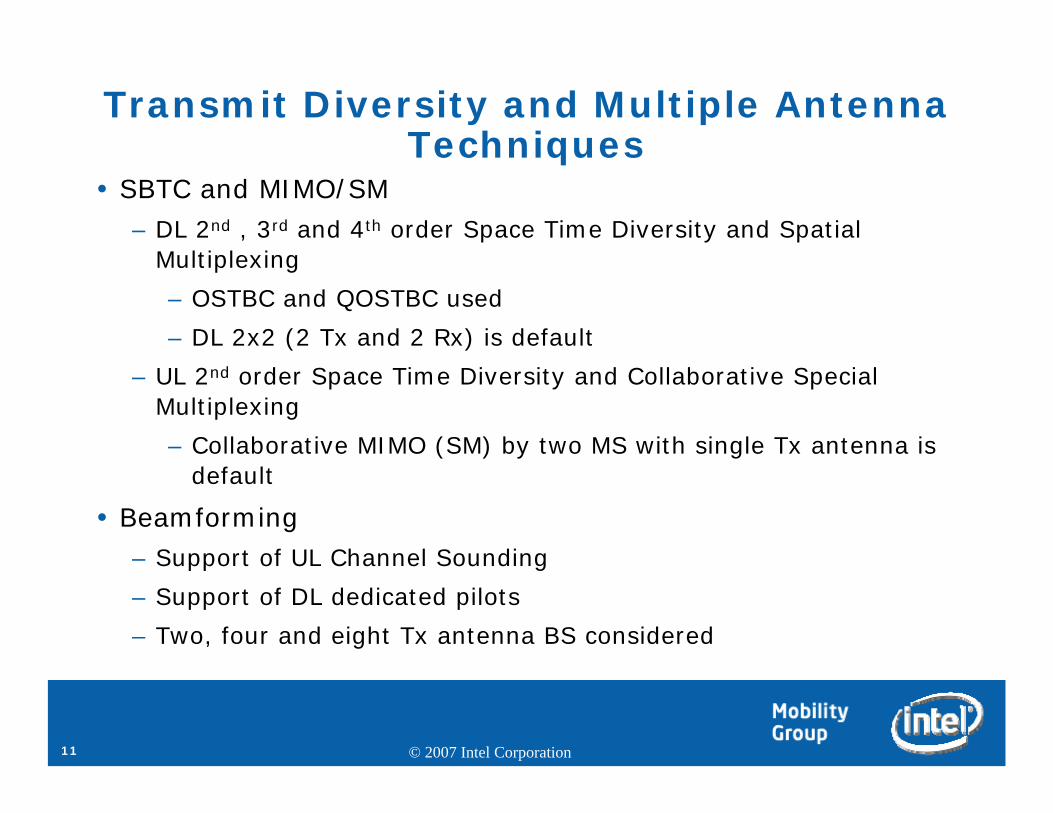
Transmit Diversity and Multiple Antenna Techniques
SBTC and MIMO/SM– DL 2nd , 3rd and 4th order Space Time Diversity and Spatial
Multiplexing
– OSTBC and QOSTBC used
– DL 2x2 (2 Tx and 2 Rx) is default
– UL 2nd order Space Time Diversity and Collaborative Special Multiplexing
– Collaborative MIMO (SM) by two MS with single Tx antenna is default
Beamforming– Support of UL Channel Sounding
– Support of DL dedicated pilots
– Two, four and eight Tx antenna BS considered

12 © 2007 Intel Corporation
STBC/SM Tx Signals: Open Loop
⎥⎦
⎤⎢⎣
⎡ −=
*
12
*
21
SSSS
A
⎥⎦
⎤⎢⎣
⎡=
2
1
SS
B
⎥⎥⎥⎥⎥
⎦
⎤
⎢⎢⎢⎢⎢
⎣
⎡
−
−
=
*
34
*
43
*
12
*
21
0000
0000
SSSS
SSSS
A
⎥⎥⎥⎥⎥
⎦
⎤
⎢⎢⎢⎢⎢
⎣
⎡
−−
−−
=
*
78
*
34
*
87
*
43
*
56
*
12
*
65
*
21
SSSSSSSS
SSSSSSSS
B
⎥⎥⎥⎥
⎦
⎤
⎢⎢⎢⎢
⎣
⎡
=
4
3
2
1
SSSS
C

13 © 2007 Intel Corporation
STBC/SM Tx Signals: Closed LoopThe space time coding output can be weighted by a matrix before mapping onto transmit antennas.
Z=W x X– X is a vector with the output from the space-time coding (per-subcarrier),– The matrix W is an weighting matrix where– Z contains the signals after weighting, i.e. the number of Beamforming
antenna– W example for mapping of 2nd order STBC/SM into four Beamforming
antenna:
A realization to maximize Ergodic capacity of the channel. Closed Loop feedback options– Quantized MIMO channel mapping at MS– Pre-coding MIMO Transmission by MS

14 © 2007 Intel Corporation
Forward Error Correction and Modulation and Coding Schemes
Convolutional Encoding– Used in DL Frame Control Header
Convolutional Turbo Code (CTC)– Default for DL and UL
Block Turbo Code (BTC)– Optional
Low Density Turbo Codes (LDPC)– Optional
HARQ– Chase Combining (default)– Incremental Redundancy
(enhanced)
3/464 QAM
1/264 QAM
5/664 QAM
2/364 QAM
3/416 QAM
1/216 QAM
3/4QPSK
1/2QPSK
Code RateModulation

15 © 2007 Intel Corporation
Support for Multiple Usage Models through Zone Switching

16 © 2007 Intel Corporation
Zone SwitchingTo switch subcarrier allocation modes, reuse factors and
multiple antenna techniquesZone Switching in DL
Subcarrier allocation mode– Diversity: PUSC, FUSC, OFUSC– Adjacent: AMC
Reuse factor– Segmented– All subchannels
Multiple antenna techniques– MIMO: 2nd, 3rd or 4th order, Matrix A, B or C– Beamforming: Broadcast or dedicated pilots
Zone Switching in ULSubcarrier allocation mode
– Diversity: PUSC, OPUSC– Adjacent: AMC
Reuse factor– Segmented– All subchannels
Multiple antenna techniques– MIMO: Single and dual transmission, collaborative and non-collaborative – Beamforming: UL subchannel rotation disabled/enabled

17 © 2007 Intel Corporation
Mobile WiMAX System: MAC Features
HO initiated by MSHand over initiation
HO initiated by BS
Request Grant MechanismRequest Grant Mechanism
RT-VR, NRT-VR
IPv6 and ROHC
BS initiated service flowQoS
MS initiated service flow
UGS, BE, ERT-VRData Delivery Services
MAC ARQARQ
PHS and IPv4Convergence Sub-layer
DescriptionMAC Feature

18 © 2007 Intel Corporation
Mobile WiMAX System: MAC Features (cont’d)
PKMv2 (Privacy Key Managements)Security
CMAC (Message Authentication Code)
No data encryption, no data authentication & 3-DES, 128Supported Cryptographic Suites
CCM-Mode 128-bit AES, CCM-Mode, AES Key Wrap with 128-bit key
Multi BS MBSMBS
Scanning and Association
HO Optimization
CID & SAID Update (Connection & Security IDs)
Idle
SleepPower saving Modes
Neighbor AdvertisementHandover
DescriptionMAC Feature

19 © 2007 Intel Corporation
• Overview of Mobile WiMAX Release 1 (IEEE 802.16e Scalable OFDMA)
• Mobile WiMAX Performance
• Mobile WiMAX Evolution
• Multihop Relay
• IEEE 802.16m Advance Air Interface
• Summary
• Additional sources
Agenda

20 © 2007 Intel Corporation
System-level performance evaluation of Mobile WiMAX Release 1: Methodology
Using the 1xEV-DV methodology adopted by 3GPP/3GPP2
Downlink considerations– Adaptive MIMO switching (AMS) between STBC and SM (2x2) – Use of suboptimal MLD for MIMO SM stream decoding
Uplink considerations– Collaborative (virtual) MIMO transmission (2nd order)– Realistic power control over all sectors of the 19-cell network
Modeling/Scheduling – Realistic MIMO channel modeling for both useful and interfering signals– Realistic PHY abstraction and link adaptation– User scheduling according to the proportional-fair approach– Chase-combining HARQ– CQI feedback delay
21 © 2007 Intel Corporation
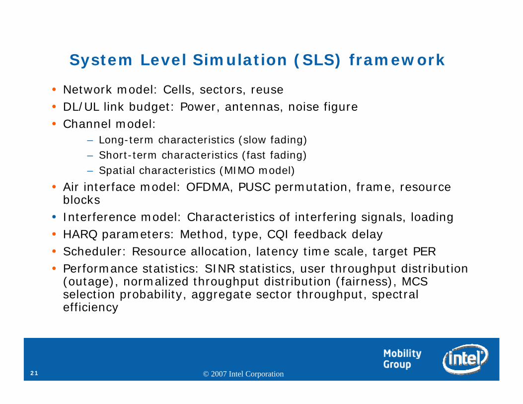
System Level Simulation (SLS) framework
Network model: Cells, sectors, reuseDL/UL link budget: Power, antennas, noise figureChannel model:
– Long-term characteristics (slow fading)– Short-term characteristics (fast fading)– Spatial characteristics (MIMO model)
Air interface model: OFDMA, PUSC permutation, frame, resource blocksInterference model: Characteristics of interfering signals, loadingHARQ parameters: Method, type, CQI feedback delayScheduler: Resource allocation, latency time scale, target PERPerformance statistics: SINR statistics, user throughput distribution (outage), normalized throughput distribution (fairness), MCS selection probability, aggregate sector throughput, spectral efficiency

22 © 2007 Intel Corporation
Adaptive MIMO Switching average SE per MCS
•The selection of spatial multiplexing modes with spectral efficiency greater than 5 bits/s/Hz leads to a dramatic increase of the overall spectral efficiency•No appreciable difference between 500 m and 1000 m BS-BS radius with respect to MCS selection probability
0 1 2 3 4 5 6 7 8 9 10 110
0.05
0.1
0.15
0.2
0.25
0.3
0.35
0.4
0.45
Spectral efficiency per MCS
Ave
rag
e sp
ectr
al e
ffic
ien
cy
1x3x1, COST−231 Hata
Radius = 500 mRadius = 1000 m
High SpectrallyEfficient SM MCSs
2x64QAM 5/610
2x64QAM 3/49
2x64QAM 2/38
2x16QAM 3/4
2x64QAM 1/26
1x64QAM 5/65
1x64QAM 3/44.5
1x64QAM 2/3
2x16QAM 1/24
1x16QAM 3/4
1x64QAM 1/2
2xQPSK 3/4
3
1x16QAM 1/2
2xQPSK 1/22
1xQPSK 3/4 1.5
1xQPSK 1/2 1
Spectral Efficiency per MCS

23 © 2007 Intel Corporation
User throughput and normalized user throughputs (A measure for proportional
fairness)
0 0.5 1 1.5 2 2.5 3 3.5 40
0.1
0.2
0.3
0.4
0.5
0.6
0.7
0.8
0.9
10.9 km; Urban pathloss; 10 users/sector
Normalized ThroughputC
DF
of
No
rma
lize
d T
hro
ug
hp
ut
CDF of the normalized user throughput for BS-to-BS separation
of 0.9 km
CDF of user throughput for BS-to-BS separation of 0.9 km
500 1000 1500 2000 2500 3000 3500 4000

24 © 2007 Intel Corporation
DL user and aggregate throughput with Adaptive MIMO Switching
720 Kbps
320 Kbps
10 users/sector
10 MHz
392 Kbps50th Percentile (Median)
175 Kbps10th Percentile (Outage)
20 users/sector
10 MHzValue
4.9510.65Reuse-1 MIMO (2x2)
6.5 / 19.32
7.37
Aggregate DL Sector Throughput (Mbps)
3.02 / 2.99Reuse-3 MIMO
(segmented/non-segmented)
3.42Reuse-1 SIMO
DL Spectral Efficiency (b/s/Hz/cell site)
System Configuration
Lower SE vs. R-1
45% Increase
vs. SIMO
0.65 x R-1
Most SE
Option

25 © 2007 Intel Corporation
UL SIMO vs. Collaborative MIMO: Aggregate sector throughput and spectral efficiency
0.59 b/s/Hz/sector
1.87 Mbps
SIMO
0.73 b/s/Hz/sectorSpectral efficiency
2.33 MbpsAggregate sector
throughput
MIMOParameter
• ITU Vehicular model• Cell radius 1.6 km
Collaborative MIMO over SIMO spectral efficiency increase is 24%.

26 © 2007 Intel Corporation
Mobile WiMAX voice capacity: 10MHz TDD, Reuse 1, Mix Mobility, VAF 0.4
1.1
2.05
95th Percentile of LT FER (%)
220
195
VoIP Capacity (users/sector)
2.3G.729 (8 Kbps)
2.9AMR (12.2 Kbps)
Users below target system outage (%)
Codec
Performance targets for VoIP Capacity:– 95th percentile of Long Term FER <3%
– System Outage < 3%
VoIP capacity (G.729, 8 Kbps) satisfying performance targets: 220 users/sector– G.729 (8Kbps) has smaller payload than AMR (12.2Kbps) but capacity increase is limited by
increased control overhead. Further optimization is possible for G.729 simulation.
VoIP capacity (AMR 12.2 Kbps) satisfying performance targets: 195 users/sector
Wave 2 enhancements position Mobile WiMAX as a highly competitive solution for Mobile Broadband. In particular, multiple antenna enhancements can achieve
additional 40-50% capacity in DL and 25% in UL over SIMO. Further gain is achievable through optimized operational scenarios.

27 © 2007 Intel Corporation
• Overview of Mobile WiMAX Release 1 (IEEE 802.16e Scalable OFDMA)
• Mobile WiMAX Performance
• Mobile WiMAX Evolution
• Multihop Relay
• IEEE 802.16m Advance Air Interface
• Summary
• Additional sources
Agenda

28 © 2007 Intel Corporation
Mobile WiMAX Evolution
Mobile WiMAX Release 1 is being commercialized by WiMAXForum®
IEEE 802.16 Standard continues evolving through various major enhancements including Multihop Relay and Advance Air Interface 802.16m considered for Mobile WiMAX Release 2.
29 © 2007 Intel Corporation
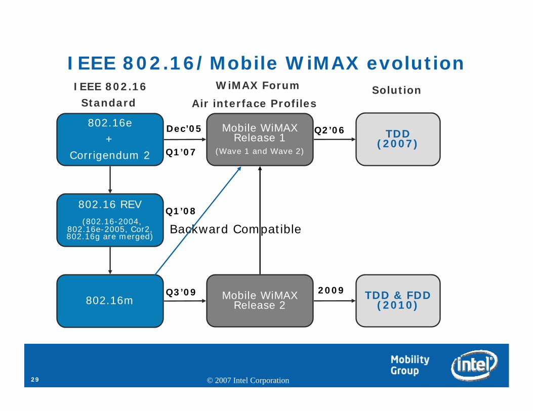
IEEE 802.16/Mobile WiMAX evolution
802.16e+
Corrigendum 2
802.16 REV(802.16-2004,
802.16e-2005, Cor2, 802.16g are merged)
802.16m
Mobile WiMAX Release 1
(Wave 1 and Wave 2)
Mobile WiMAX Release 2
TDD (2007)
TDD & FDD (2010)
IEEE 802.16Standard
WiMAX Forum
Air interface ProfilesSolution
Backward Compatible
Dec’05
Q1’07
Q1’08
Q3’09
Q2’06
2009
30 © 2007 Intel Corporation
• Overview of Mobile WiMAX Release 1 (IEEE 802.16e Scalable OFDMA)
• Mobile WiMAX Performance
• Mobile WiMAX Evolution
• Multihop Relay
• IEEE 802.16m Advance Air Interface
• Summary
• Additional sources
Agenda

31 © 2007 Intel Corporation
OFDMA PHY and MAC enhancements to IEEE Std 802.16,
Licensed bands to enable the operation of Relay Stations,
Subscriber station specifications are not changed,
Specifying 802.16 multihop relay capabilities and functionalities of interoperable relay stations and base stations,
Amendment is to enhance coverage, throughput and system capacity of 802.16 networks,
Control functions may be centralized at the Base Station or distributed among the Relay Stations with central coordination from the Base Station.
Mobile Multihop Relay project: Purposes and scopes

32 © 2007 Intel Corporation
What is Mobile Multihop Relay (MR)? Is not Mesh, more than wireless backhaul!
RS
RS
RS
RS
MR-BS
Data communications between BS and MS – no direct communication of data between MS;Control of cell is centrally coordinated by BS
Fixed/Portable, Mobile and Client Based Relay Stations are considered
Backhaul and access links can share radio resources Control is distributed between BS and RSs
Tree-like structure,BS-MS communications traverse zero or more backhaul links and an access link,Redundant routs are possible

33 © 2007 Intel Corporation
Coverage, Capacity, and QoS enhancement relative to conventional Cellular deployments
Current deployments suffer from …
– Low SINR at cell edge
– Coverage holes due to shadowing
– Out-of-range clusters of users
– Non-uniformly distributed traffic load (e.g. hot spots)
– Limited spectrum and/or insufficient wire-line capacity
Reducing cell size improves conditions, but issues are…
– Limited availability of wire-line infrastructure in developing markets
– Limited access to traditional cell site locations
– Prohibitive installation and operating costs (backhaul is large fraction)
Providing fault tolerant service is difficult and expensive
– Redundant equipment, backhaul, backup power at cell sites is costly

34 © 2007 Intel Corporation
Key MR technology areas Frame structure
– Critical to enabling flexible and efficient radio resource usage
Scheduling structure and algorithms
– Key to high efficiency
Frequency assignment and reuse
– Improves interference mitigation and efficiency
Routing structure and algorithms
– Enables load balancing and fault tolerance
– Enhances efficiency
Mobility management
– Critical to support hit-less handover and mobile RS

35 © 2007 Intel Corporation
Frame structure options
In-band Relay – access and relay links share a channel– Non-transparent Relay –RS does transmit preamble and MAPs
– Supports both Centralized and Distributed control
– Mainly targeting coverage enhancement
– Transparent Relay – RS does not transmit preamble or MAPs
– Supports both Centralized control
– Mainly targeting capacity enhancement
Out-of-band Relay – Relay links operate on a separate channel

36 © 2007 Intel Corporation
Trade off space: throughput, range, and number of hops
• For any given range there exists an optimal hop number that maximizes end-to-end throughput
• Optimal number of hops increases for longer ranges
• Other considerations such as latency limits for applications such as voice limit the number of hops that can be deployed in practice.
Number of hops
d4
d3
d2
d1
Decreasing Range
Mea
n s
pec
tral
effic
iency

37 © 2007 Intel Corporation
• Overview of Mobile WiMAX Release 1 (IEEE 802.16e Scalable OFDMA)
• Mobile WiMAX Performance
• Mobile WiMAX Evolution
• Multihop Relay
• IEEE 802.16m Advance Air Interface
• Summary
• Additional sources
Agenda

38 © 2007 Intel Corporation
IEEE 802.16/Mobile WiMAX evolution (revisited)
802.16e+
Corrigendum 2
802.16 REV(802.16-2004,
802.16e-2005, Cor2, 802.16g are merged)
802.16m
Mobile WiMAX Release 1
(Wave 1 and Wave 2)
Mobile WiMAX Release 2
TDD (2007)
TDD & FDD (2010)
IEEE 802.16Standard
WiMAX Forum
Air interface ProfilesSolution
Dec’05
Q1’07
Q1’08
Q3’09
Q2’06
2009
Backward Compatible

39 © 2007 Intel Corporation
Advanced Air Interface project: Purposes and scopes from 802.16m PAR
802.16m amends the IEEE 802.16 WirelessMAN-OFDMA specification to provide an advanced air interface for operation in licensed bands. It meets the cellular layer requirements of IMT-Advanced next generation mobile networks. This amendment provides continuing support for legacy WirelessMAN-OFDMA equipment.The project seek to develop an advanced IEEE 802.16 air interface by working cooperatively with ITU-R and its members.Some of the specific requirements that this amendment will target are: – 100 Mbit/s - high mobility – Frequency bands - licensed mobile bands below 6 GHz – Target cell size- Micro and Macro-cells as defined in Table 7-15 of Report
ITU-R M.207

40 © 2007 Intel Corporation
802.16m Advance Air Interface Requirements
Below 6 GHz, licensed RF Bands
TDD and FDD/HFDDDuplexing Modes
5, 10, 20, others optional BWsChannel Bandwidths
DL: 2x2, 2x4, 4x2, 4x4 MIMOUL: 1x2, 1x4, 2x2, 2x4 MIMO
MIMO Configuration
Up to 350 km/hrMobility
> 75 users/sector/FDD MHz> 37 users/sector/TDD MHz
Number of VoIP Active Users
< 5 km: Optimized
5-30 km: Graceful degradation
30-100 km: Functional, coverage limited
Coverage (km)
Peak: DL > 6.5 bps/HzUL > 2.8 bps/Hz
Spectral efficiency (per sector)
Link-Layer Access: <10ms Handoff: <50ms
Latency
DL: > 130 Mbps
UL: > 56 Mbps
(20 MHz)
Peak Data Rates (per sector)
IEEE 802.16mFeature

41 © 2007 Intel Corporation
802.16m/Mobile WiMAX R2 Candidate Targets
2.3 GHz, 2.5GHz, 3.3-3.8GHz, IMT-Advanced bands
2.3 GHz, 2.5GHz, 3.3-3.8GHzRF Bands
TDD, FDD/HFDDTDDDuplexing Modes
5, 10, 20, 40 MHz5, 3.5, 7, 8.75, 10 MHzChannel Bandwidths
DL: 2x2, 2x4, 4x2, 4x4 MIMOUL: 1x2, 1x4, 2x2, 2x4 MIMO
DL: 2x2 MIMOUL: 1x2 MIMO
MIMO Configuration
Up to 350 km/hrUp to 60-120 km/hrMobility
> 100 users/sector/FDD MHz> 50 users/sector/TDD MHz
~ 50 users/sector/FDD MHz~ 25 users/sector/TDD MHz
Number of VoIP Active Users
1/5/30km (Optimal performance at 5km)1/5/30 kmCoverage (km)
Peak: DL > 17.5 bps/HzUL > 10 bps/Hz
Sustained: DL > 2.5 bps/Hz,UL > 1.16 bps/Hz
Peak: DL 6.4 bps/Hz, UL 2.8 bps/Hz
Sustained: DL 1.7 bps/Hz, UL 0.78 bps/Hz
Spectral efficiency (per sector)
Link-Layer Access: <10ms Handoff: <20ms
Link-Layer Access: ~20ms Handoff: ~35-50msLatency
DL: > 350 Mbps (4x4)
UL: > 200 Mbps (2x4)
(20 MHz)
DL: 64 Mbps (2x2)
UL: 28 Mbps (2x2 collaborative MIMO)
(10 MHz)
Peak Data Rates(per sector)
Mobile WiMAX R2 (802.16m)
(Expected Performance)
Mobile WiMAX R1* (802.16e)Feature

42 © 2007 Intel Corporation
• Overview of Mobile WiMAX Release 1 (IEEE 802.16e Scalable OFDMA)
• Mobile WiMAX Performance
• Mobile WiMAX Evolution
• Multihop Relay
• IEEE 802.16m Advance Air Interface
• Summary
• Additional sources
Agenda

43 © 2007 Intel Corporation
SummaryMobile WiMAX is a globally defined standard currently undergoing trial and interoperability.
Release 1.0 advanced features position Mobile WiMAX as a highly competitive solution for Mobile Broadband. In particular, multiple antenna enhancements can achieve additional 40-50% capacity in DL and 25% in UL over SIMO. Further gain is achievable through optimized operational scenarios.
MR technology provides opportunities to enhance Coverage, Capacity, and QoS of Mobile WiMAX performance relative to conventional Cellular deployments.
IEEE 802.16m Advanced Air Interface project targets the cellularlayer requirements of IMT-Advanced next generation mobile networks.

44 © 2007 Intel Corporation
Additional sources of information on this topic
More web based info:–http://www.wimaxforum.org–http://www.wimaxforum.org/technology/documents/–http://www.wimaxforum.org/technology/downloads/–http://www.ieee802.org/16/

45 © 2007 Intel Corporation