mobility and disaster recovery solution for virtualized ... · in the system test field and led the...
TRANSCRIPT

Mobility and Disaster Recovery Solution forVirtualized Tier-1 Enterprise ApplicationsWhite PaperLast Updated: February 3, 2012

Cisco Validated Design2
About the Authors
David Antkowiak
3
Ramesh Issac
Haseeb Niazi
About the Authors
David Antkowiak, Consulting Systems Engineer, US Data Center—Enterprise, Cisco Systems
David Antkowiak is a Consulting Systems Engineer with the Data Center Enterprise South
Sales Team. With over 11 years of experience in various private and government organiza-
tions, his areas of focus have included virtual desktop infrastructure, server virtualization,
cloud migration, and storage design. Prior to joining Cisco, David was Solutions Architect at
JetBlue. David holds a masters degree from Florida State University and certifications from
VMware and Microsoft.
Ramesh Isaac, Technical Marketing Engineer, Systems Development Unit, Cisco Systems
Ramesh Isaac has worked in data center and mixed-use lab settings since 1995. He started
in information technology supporting UNIX environments and focused on designing and
implementing multi-tenant virtualization solutions in Cisco labs over the last couple of years.
Ramesh holds certifications from Cisco, VMware, and Red Hat.
Haseeb Niazi, Solutions Architect, Systems Development Unit, Cisco Systems
Haseeb Niazi is a Solutions Architect in the Systems Development Unit (SDU) based in RTP
North Carolina. Haseeb has over twelve years of experience in multi-tenancy, security, and
data center related technologies. As a member of various Solution Teams and Advanced
Services, he has helped a large number of enterprise and service provider customers eval-
uate and deploy a wide range of Cisco solutions.
Haseeb holds a masters degree in computer engineering from University of Southern Cali-
fornia and regularly presents to both internal and external audiences at various conferences
and customer events.

About the Authors
Scott Bookman
Andrew Feldmann
Marina Kvitnitsky
About the Authors
Scott Bookman, Senior Program Manager (Technical), EMC
Scott Bookman is a Senior Program Manager (Technical) in EMC's RecoverPoint VPLEX
Business Unit. He joined VPLEX after spending time in information technology developing
mission and business critical remote application solutions. Scott started his career in 2003
in the system test field and led the effort to build a test center of excellence in 2007. In 2008,
he switched to engineering program management and his current focus is on storage virtu-
alization with EMC's VPLEX technology.
Andrew Feldmann, Corporate Systems Engineer, EMC
Andrew Feldmann is an EMC Corporate Systems Engineer with the RecoverPoint VPLEX
Business Unit specializing in the VPLEX product. He has 5 years experience with the VPLEX
technology and over 20 years experience in the computer and data storage field.
Marina Kvitnitsky, Product Manager, EMC
Marina Kvitnitsky is a Product Manager for VPLEX, a product within the EMC RecoverPoint
VPLEX Business Unit. Marina has been with EMC as a Product and Program Manager for the
last three years. Prior to EMC, Marina has worked as a Product Manager for products rang-
ing from chip design at ChipWrights to IP Video Servers at Tyco Security Products. Marina
holds BS in Physics and MSEE in ElectroOptics.
4
ALL DESIGNS, SPECIFICATIONS, STATEMENTS, INFORMATION, AND RECOMMENDATIONS (COLLEC-
TIVELY, "DESIGNS") IN THIS MANUAL ARE PRESENTED "AS IS," WITH ALL FAULTS. CISCO AND ITS SUP-
PLIERS DISCLAIM ALL WARRANTIES, INCLUDING, WITHOUT LIMITATION, THE WARRANTY OF
MERCHANTABILITY, FITNESS FOR A PARTICULAR PURPOSE AND NONINFRINGEMENT OR ARISING
FROM A COURSE OF DEALING, USAGE, OR TRADE PRACTICE. IN NO EVENT SHALL CISCO OR ITS
SUPPLIERS BE LIABLE FOR ANY INDIRECT, SPECIAL, CONSEQUENTIAL, OR INCIDENTAL DAMAGES,
INCLUDING, WITHOUT LIMITATION, LOST PROFITS OR LOSS OR DAMAGE TO DATA ARISING OUT OF
THE USE OR INABILITY TO USE THE DESIGNS, EVEN IF CISCO OR ITS SUPPLIERS HAVE BEEN ADVISED
OF THE POSSIBILITY OF SUCH DAMAGES.
THE DESIGNS ARE SUBJECT TO CHANGE WITHOUT NOTICE. USERS ARE SOLELY RESPONSIBLE FOR
THEIR APP
OTHER PRO
THEIR OWN
DEPENDING
The Cisco i
University o
tem. All righ
Cisco and t
countries. A
party trade
does not im
Any Interne
actual addr
grams, and
actual IP ad
Mobility an
© 2012 Cis
LICATION OF THE DESIGNS. THE DESIGNS DO NOT CONSTITUTE THE TECHNICAL OR
FESSIONAL ADVICE OF CISCO, ITS SUPPLIERS OR PARTNERS. USERS SHOULD CONSULT
TECHNICAL ADVISORS BEFORE IMPLEMENTING THE DESIGNS. RESULTS MAY VARY
ON FACTORS NOT TESTED BY CISCO.
mplementation of TCP header compression is an adaptation of a program developed by the
f California, Berkeley (UCB) as part of UCB’s public domain version of the UNIX operating sys-
ts reserved. Copyright © 1981, Regents of the University of California.
he Cisco Logo are trademarks of Cisco Systems, Inc. and/or its affiliates in the U.S. and other
listing of Cisco's trademarks can be found at http://www.cisco.com/go/trademarks. Third
marks mentioned are the property of their respective owners. The use of the word partner
ply a partnership relationship between Cisco and any other company. (1005R)
t Protocol (IP) addresses and phone numbers used in this document are not intended to be
esses and phone numbers. Any examples, command display output, network topology dia-
other figures included in the document are shown for illustrative purposes only. Any use of
dresses or phone numbers in illustrative content is unintentional and coincidental.
d Disaster Recovery Solution for Virtualized Tier-1 Enterprise Applications
co Systems, Inc. All rights reserved.
5

Mobility and Disaster Recovery Solution for Virtualized Tier-1 Enterprise Applications
IntroductionTo meet ever growing IT infrastructure needs and to ensure business continuity in case of a site-level disaster, it is critical to have live mobility and fully automated, efficient disaster recovery (DR) processes for virtualized enterprise applications across data centers. Failure to have a robust and efficient mobility and fully automated disaster recovery solution can result in millions of dollars of lost revenue and employee productivity.
This white paper showcases a flexible solution from Cisco®, VMware®, and EMC® that allows customers to efficiently achieve live mobility and fully automated DR for virtualized enterprise applications across data centers with less than 10ms round-trip time (RTT) latency between them.
Live mobility for virtualized applications across data centers enables IT organizations to efficiently meet various operational needs, e.g., data capacity expansion, seamless migrations, disaster avoidance, etc.
Fully automated DR allows customers to protect their mission critical enterprise applications against site-level disasters and ensures business continuance. A key advantage of this solution over manual, runbook style DR process execution is “minimum downtime with lowest Recovery Time Objective (RTO)”. This is extremely critical for next generation cloud solutions required to host hundreds to thousands of virtualized applications on the same shared infrastructure.
The Cisco, VMware, and EMC design presented in this white paper is very modular so that, based on customer requirements, there is flexibility to deploy both the live mobility and fully automated DR solution or deploy any one of these solutions.
Microsoft® Virtualized SharePoint 2010 (http://sharepoint.microsoft.com/en-us/Pages/default.aspx) with Microsoft SQL Server 2008 R2 (http://www.microsoft.com/sqlserver/en/us/default.aspx) in the backend and an Oracle® 11g database (http://www.oracle.com/technetwork/database/enterprise-edition/downloads/index.html) are the key tier-1 applications validated in this white paper. Industry standard application load generation test tools, e.g., Swingbench (Oracle, http://dominicgiles.com/swingbench.html) and Visual Studio® (SharePoint, http://www.microsoft.com/visualstudio/en-us/products/2010-editions), were leveraged to simulate client-server traffic on these applications as the validation for the two solutions (i.e., live mobility and fully automated DR) was performed.
Corporate Headquarters:
Copyright © 2011 Cisco Systems, Inc. All rights reser
Cisco Systems, Inc., 170 West Tasman Drive, San Jose, CA 95134-1706 USA

Introduction
Note Note that this is not a sizing or deployment guide. Detailed sizing exercises and step-by-step deployment procedures are outside the scope of this white paper. For detailed sizing guidelines and step-by-step deployment instructions, contact your Cisco, VMware, and EMC representatives.
Target AudienceThis white paper is primarily targeted towards architects, engineers, and application owners involved in making key design decisions, Cisco and partner field engineers, and anyone else looking for guidance on designing a live mobility or fully automated DR solution for virtualized enterprise applications.
The design showcased in the white paper is primarily targeted towards large customers with mixed enterprise application workload, however the solutions described can easily be leveraged for mid-size or small environments.
Reference DocumentsHere are the key documents leveraged in the design and validation of the solutions showcased in this white paper.
• Cisco
– Cisco Virtualized Workload Mobility Design Considerationshttp://www.cisco.com/en/US/docs/solutions/Enterprise/Data_Center/DCI/4.0/EMC/EMC_2.html
– Cisco Overlay Transport Virtualization (OTV)http://www.cisco.com/en/US/prod/switches/ps9441/nexus7000_promo.html
– Cisco Locator/ID Separation Protocol (LISP)http://www.cisco.com/en/US/products/ps10800/products_ios_protocol_option_home.html
• VMware
– VMware vCenter Site Recovery Manager 5 Evaluator Guidehttp://www.vmware.com/files/pdf/products/SRM/VMware-vCenter-Site-Recovery-Manager-Evaluation-Guide.pdf
– VMware vSphere vMotion Architecture, Performance and Best Practices in VMware vSphere 5http://www.vmware.com/files/pdf/vmotion-perf-vsphere5.pdf
• EMC
– Using VMware vSphere with EMC VPLEXhttp://www.emc.com/collateral/hardware/white-papers/h7118-using-vmware-virtualization-platforms-vplex.pdf
– Improving VMware Disaster Recovery with EMC RecoverPointhttp://www.emc.com/collateral/software/white-papers/h2352-improving-vmware-dstr-rcvry-emc-recoverpoint-wp.pdf
– VPLEX Metro 5.0 and Application Mobilityhttp://www.emc.com/collateral/hardware/white-papers/vplex-metro-app-mobility-vsphere.pdf
7Mobility and Disaster Recovery Solution for Virtualized Tier-1 Enterprise Applications

Solution Summary
Solution SummaryThis section summarizes the key values and the enabling technologies for the solutions that can help customers build a robust live mobility and fully automated DR solution for virtualized tier-1 enterprise applications.
Solution 1—Live mobilityThe key solution highlights and the enabling Cisco, VMware, and EMC technologies are:
• Automated virtualized applications mobility across data centers with up to 10 ms. RTT latency enabled by VMware vMotionTM.
• Seamless mobility and eliminating the need to re-IP the application VMs after vMotion enabled by Cisco Overlay Transport Virtualization (OTV). OTV enables networking Layer 2 extension across data centers to make vMotion seamless.
• Network route optimization for the client-server traffic after vMotion enabled by Cisco LISP. LISP ensures that after vMotion the client-server application traffic does not have to traverse one data center to get to the other data center where the application was moved using vMotion.
• Seamless virtualized application data (OS, application binaries, application data) availability across data centers enabled by EMC VPLEXTM. VPLEX eliminates the need for manual, time consuming VM data migrations across data centers.
Solution 2—Fully Automated DR (with Minimum RTO)The key solution highlights and the enabling Cisco, VMware, and EMC technologies are:
• Fully orchestrated site failover and failback (with minimum downtime) enabled by VMware SRM.
• No need to re-IP the application VMs after failover or failback, enabled by Cisco OTV.
• Network route optimization for the client-server traffic after failover and failback enabled by Cisco LISP. LISP ensures that after failover/failback, the client-server application traffic does not have to traverse the origin data center to get to the other data center where the virtualized application was recovered.
• Efficient, WAN optimized remote replication of virtualized application data enabled by EMC RecoverPoint.
High Level Solution ArchitectureFigure 1 shows the high level overview of the architecture to achieve live mobility and fully automated DR for enterprise applications across two data centers with 10 ms. RTT latency between them. Client-server application traffic was simulated from a remote branch office connected over WAN. Both data centers have compute, network, and storage components from Cisco, VMware, and EMC to efficiently run the virtualized applications. Both data centers are active and connected by a 10 Gbps Ethernet WAN link for IP communication and 4G FC link (using dark fiber) to enable storage replication for the live mobility solution.
8Mobility and Disaster Recovery Solution for Virtualized Tier-1 Enterprise Applications

High Level Solution Architecture
Figure 1 Design Overview
High Level Physical Architecture
Data Center Design
Figure 2 shows the physical architecture that enables both the live mobility and fully automated DR solutions. The architecture is enabled by key compute, network, and storage components from Cisco and EMC.
2921
43
Site A
APPOS
APPOS
APPOS
Short Distance between sites < 10ms RTT Latency
4Gbps FC and 10Gbps WAN Links
UCS 5108
OK FAIL
! ResetConsole
! !UCS B200 M1
1 2
3 4
5 6
7 8
! ResetConsole
! !UCS B200 M1
! ResetConsole
! !UCS B200 M1
! ResetConsole
! !UCS B200 M1
! ResetConsole
! !UCS B200 M1
! ResetConsole
! !UCS B200 M1
! ResetConsole
! !UCS B200 M1
! ResetConsole
! !UCS B200 M1
OK FAIL OK FAIL OK FAIL
Site B
APPOS
APPOS
APPOS
UCS 5108
OK FAIL
! ResetConsole
! !UCS B200 M1
1 2
3 4
5 6
7 8
! ResetConsole
! !UCS B200 M1
! ResetConsole
! !UCS B200 M1
! ResetConsole
! !UCS B200 M1
! ResetConsole
! !UCS B200 M1
! ResetConsole
! !UCS B200 M1
! ResetConsole
! !UCS B200 M1
! ResetConsole
! !UCS B200 M1
OK FAIL OK FAIL OK FAIL
9Mobility and Disaster Recovery Solution for Virtualized Tier-1 Enterprise Applications

High Level Solution Architecture
Figure 2 Data Center Physical Layout
Data Center Physical Components
The key physical components leveraged in the validation of the solutions described in this white paper are:
• Compute
– Cisco Unified Computing SystemTM (UCSTM, http://www.cisco.com/en/US/products/ps10265/index.html) composed of B200M2 blades, UCS 5100 chassis, 6120 Fabric Interconnect, and M81KR Virtual Interface Card (VIC)
• Networking
– Access layer—Cisco Nexus® 1000V (http://www.cisco.com/en/US/products/ps9902/index.html)and Cisco Nexus 5020 (http://www.cisco.com/en/US/products/ps9670/index.html)
– Core/aggregation layer—Cisco Nexus 7000 (http://www.cisco.com/en/US/products/ps9402/index.html)
• Storage and data replication
– Storage networking—Cisco MDS 9513 SAN switches
– EMC VNXTM 5300 Unified Storage
– EMC VPLEX Metro
Aggregation
Access
Compute
Storage
Cisco Nexus 7000
Cisco Nexus 5020
vPC
Fabric A
vPCvPC
CiscoMDS 9513
CiscoUCS 6100FabricInterconnect
Cisco UCS B200M2Blade Servers
EMC VPLEX Metro
RecoverPoint
4x10GE 4x10GE
Aggregation
Access
Compute
Storage
Cisco Nexus 7000
Cisco Nexus 5020
<10msRTT
Latency
DarkFiber
vPC
vPCvPC
CiscoMDS 9513
CiscoUCS 6100FabricInterconnect
Cisco UCS B200M2Blade Servers
EMC VPLEX Metro
RecoverPoint
4x10GE 4x10GE
2921
44
Fabric B
EMC VNX 5300
4x10GE 4x10GE
EMC VNX 5300
4x10GE 4x10GE
10Mobility and Disaster Recovery Solution for Virtualized Tier-1 Enterprise Applications

High Level Solution Architecture
– EMC RecoverPoint (http://www.emc.com/replication/recoverpoint/recoverpoint.htm)
Branch Design
The client virtual machines running the application load generation test tools (Swingbench and Microsoft Visual Studio) were hosted on a small virtual infrastructure outside the data centers in a typical WAN branch office setup. The branch office had network connectivity to both the data centers over MPLS to ensure continuity of client-server I/O after live mobility of virtualized applications or DR failover/failback. Routing was setup such that application traffic was routed to Data Center 1. In case of Data Center 1 failure, traffic destined to the application network would be re-routed to the Data Center 2 within the MPLS cloud. Cisco LISP was set up on the branch router as well. Cisco ISR 3945 was deployed as the branch router.
Figure 3 Remote Branch Office Connected over WAN
Solution Components and Technology DescriptionsThis section provides brief descriptions of the various components leveraged in the solutions.
Compute
Cisco Unified Computing System
Cisco Unified Computing System combines compute, network, storage access, and virtualization providing a 10 Gigabit Ethernet unified network fabric with an enterprise class server architecture. The Cisco UCS is designed to deliver:
• Reduced TCO at the platform, site, and organizational levels
• Increased IT staff productivity and business agility through just-in-time provisioning and mobility support
• A cohesive, integrated system that is managed, serviced, and tested as a whole
• Scalability through a design for hundreds of discrete servers and thousands of virtual machines and the capability to scale I/O bandwidth to match demand
• Industry standards supported by a partner ecosystem of industry leaders
2921
45
MPLS
Data Center 1Core Nexus 7Ks
Data Center 1WAN Edge ASR 1Ks
Data Center 2Core Nexus 7Ks
Data Center 2WAN Edge ASR 1Ks
Branch ISR 3945
11Mobility and Disaster Recovery Solution for Virtualized Tier-1 Enterprise Applications

High Level Solution Architecture
For detailed information on Cisco UCS, see: http://www.cisco.com/en/US/netsol/ns944/index.html.
Cisco UCS Manager
Cisco UCS Manager provides a unified management domain with centralized management capabilities. It is an embedded device management software that manages the system end-to-end as a single logical entity through an intuitive GUI, a command line interface (CLI), or an XML API. For detailed information on UCS Manager, see: http://www.cisco.com/en/US/products/ps10281/index.html.
Cisco UCS Service Profiles
Service profiles capability in UCS Manager enables rapid provisioning of servers. Service profile templates consist of server requirements and the associated LAN and SAN connectivity. When a service profile is deployed to a server, Cisco UCS Manager automatically configures the server, adapters, fabric extenders, and fabric interconnects to match the configuration specified in the service profile. This automation of device configuration reduces the number of manual steps required to configure servers, network interface cards (NICs), host bus adapters (HBAs), and LAN and SAN switches. For detailed information on Service Profiles, see: http://www.cisco.com/en/US/prod/collateral/ps10265/ps10281/white_paper_c11-590518.html.
UCS 6100 XP Series Fabric Interconnect
The Cisco UCS 6100 Series Fabric Interconnects are a core part of the Cisco UCS, providing both network connectivity and management capabilities for the system. The Cisco UCS 6100 Series offers line-rate, low-latency, lossless 10 Gigabit Ethernet and Fibre Channel over Ethernet (FCoE) functions.
The Cisco UCS 6100 Series provides an integrated and unified management and communication backbone for the Cisco UCS B-Series Blade Servers and UCS 5100 Series Blade Server Chassis. Management systems in older classical server designs employ a series of interfaced software management modules that are interconnected to give the appearance of a unified system until the need to troubleshoot them reveals their inherent complexity and increased operational costs for your IT team. All chassis, and therefore all blades, attached to the Cisco UCS 6100 Series Fabric Interconnects become part of a single, highly-available unified management domain. In addition, by supporting unified fabric, the Cisco UCS 6100 Series provides both the LAN and SAN connectivity for all blades within its domain. For detailed information on UCS 6100 XP fabric interconnects, see: http://www.cisco.com/en/US/products/ps10276/index.html.
Cisco UCS M81KR VIC
The Cisco UCS blade server has various Converged Network Adapters (CNA) options. The UCS M81KR Virtual Interface Card (VIC) option was used in this white paper. UCS M81KR VIC provides the capability to create multiple vNICs on the CNA. This allows complete I/O configurations to be provisioned in virtualized or non-virtualized environments using just-in-time provisioning, providing tremendous system flexibility and allowing consolidation of multiple physical adapters. For detailed information on Cisco UCS M81KR VIC, see: http://www.cisco.com/en/US/prod/collateral/ps10265/ps10280/data_sheet_c78-525049.html.
12Mobility and Disaster Recovery Solution for Virtualized Tier-1 Enterprise Applications

High Level Solution Architecture
Networking
Cisco Nexus 1000V Virtual Switch
Cisco Nexus 1000V Series Switches are virtual machine access switches that are an intelligent software switch implementation for VMware vSphere environments. Operating inside the VMware ESXi hypervisor, the industry-unique Cisco Nexus 1000V Series supports Cisco VN-Link server virtualization technology to provide policy-based VM connectivity, mobile VM security, network policy, and a non-disruptive operational model for your server virtualization and networking teams. Developed in close collaboration with VMware, the Cisco Nexus 1000V Series is certified by VMware to be compatible with VMware vSphereTM, vCenterTM, ESX, and ESXi. For detailed information on the Cisco Nexus 1000V, see: http://www.cisco.com/en/US/netsol/ns894/index.html.
Cisco Nexus 5000
Cisco Nexus 5000 Series Switches provide a unified, converged fabric over 10 Gigabit Ethernet for LAN, SAN, and cluster traffic. This unification enables network consolidation and greater utilization of previously separate infrastructure and cabling, reducing by up to 50 percent the number of adapters and cables required and eliminating redundant switches. These multipurpose, multilayer switches are deployed at the access layer and provide:
• High-performance, low-latency 10 Gigabit Ethernet delivered by a cut-through switching architecture for 10 Gigabit Ethernet server access in next-generation data centers
• Fibre Channel over Ethernet (FCoE)-capable switches that support emerging IEEE Data Center Bridging (DCB) standards to deliver a lossless Ethernet service with no-drop flow control
• Unified ports that support Ethernet, Fibre Channel, and FCoE
• A variety of connectivity options: Gigabit, 10 Gigabit (fiber and copper), FCoE, and Fibre Channel
• Converged fabric with FCoE for network consolidation, reducing power and cabling requirements and simplifying data center networks, especially for SAN consolidation of Fibre Channel
• Virtual machine-optimized services for higher asset utilization, simplified server connections, rapid server provisioning, security, and quality of service (QoS)
Cisco Nexus 7000
Cisco Nexus 7000 Series offers an end-to-end solution in one platform for data center core, aggregation, and high-density, end-of-row and top-of-rack server connectivity. The Cisco Nexus 7000 Series platform runs on Cisco NX-OS Software. It was designed around three principles:
• Infrastructure scalability—Virtualization, efficient power and cooling, high density, and performance all support efficient data center infrastructure growth.
• Operational continuity—The Cisco Nexus design integrates hardware, NX-OS software features, and management to support zero-downtime environments.
• Transport flexibility—You can incrementally and cost-effectively adopt new networking innovations and technologies, such as Cisco Overlay Transport Virtualization (OTV), Cisco FabricPath, Fibre Channel over Ethernet (FCoE), Cisco Locator/ID Separation Protocol (LISP), and Cisco IOS Multiprotocol Label Switching (MPLS).
For detailed information about Cisco Nexus 7000 Series Switches, see: http://www.cisco.com/en/US/products/ps9402/index.html.
13Mobility and Disaster Recovery Solution for Virtualized Tier-1 Enterprise Applications
High Level Solution Architecture
Storage
Cisco MDS 9513 SAN Switches
The Cisco MDS 9513 Multilayer Director is a high-performance, protocol-independent, director-class SAN switch that meets stringent enterprise data center storage requirements. Compatible with all generations of Cisco MDS 9000 switching modules, it provides high availability, scalability, security, and transparent integration of intelligent features.
For detailed information about Cisco MDS Series FC SAN Switches, see: http://www.cisco.com/en/US/products/ps6780/index.html.
EMC VNX 5300 Unified Storage
The VNX Family offers customers simple, efficient, affordable, and powerful unified storage optimized for virtualized application environments. With the EMC FAST Suite, VNX customers can cost-effectively leverage the benefits of Flash performance—with “no compromise”. The VNX Family dramatically simplifies the deployment and management of virtualized applications, including those from Microsoft, Oracle, and virtual desktop infrastructure (VDI) solutions from VMware and Citrix.
For detailed information about EMC VNX, see: http://www.emc.com/storage/vnx/vnx-series.htm.
EMC VPLEX
EMC VPLEX is unique virtual storage technology that federates data located on multiple storage systems—EMC and non-EMC—allowing the storage resources in multiple data centers to be pooled together and accessed anywhere. When combined with virtual servers, it is a critical enabler of private and hybrid cloud computing and the delivery of IT as a flexible, efficient, reliable, and resilient service.
EMC VPLEX represents the next-generation architecture for data mobility and information access. This architecture is based on EMC’s 20-plus years of expertise in designing, implementing, and perfecting enterprise-class intelligent cache and distributed data protection solutions.
VPLEX resides between the servers and heterogeneous storage assets and has unique characteristics in its architecture:
• Scale-out clustering hardware lets you start small and grow big with predictable service levels.
• Advanced data caching utilizes large-scale SDRAM cache to improve performance and reduce I/O latency and array contention.
• Distributed cache coherence provides automatic sharing, balancing, and failover of I/O within and between VPLEX clusters.
• A consistent view of one or more LUNs between VPLEX clusters separated either by a few feet within a data center or across asynchronous RTT distances enables new models of high availability, workload mobility, and collaboration.
EMC VPLEX Family Overview
The EMC VPLEX family today consists of:
• VPLEX Local for managing data mobility and access within the data center using a single VPLEX cluster.
14Mobility and Disaster Recovery Solution for Virtualized Tier-1 Enterprise Applications

High Level Solution Architecture
• VPLEX Metro for mobility and access across two locations separated by inter-site RTT of up to 5 ms.1 VPLEX Metro uses two VPLEX clusters and includes the unique capability where a remote VPLEX Metro cluster can present LUNs without the need for physical storage for those LUNs at the remote cluster. It also supports synchronous distributed volumes that mirror data between the two clusters using write-through caching.
• VPLEX Geo, which also uses two VPLEX clusters, adds access between two sites over extended asynchronous distances with RTT latencies up to 50 ms. VPLEX Geo distributed volumes support AccessAnywhere distributed mirroring using write-back caching.
VPLEX addresses three distinct customer requirements:
• Mobility—The ability to move applications and data across different storage installations—within the same data center, across a campus, or within a geographical region. And now, with VPLEX Geo, users can move data across even greater distances.
• Availability—The ability to create high-availability storage infrastructure across these same varied geographies with unmatched resiliency.
• Collaboration—The ability to provide efficient real-time data collaboration over distance for such “big data” applications as video, geographic/oceanographic research, and others.
VPLEX URLs
VPLEX Overview: http://www.emc.com/storage/vplex/vplex.htm#!
VPLEX Data Sheet: http://www.emc.com/collateral/hardware/data-sheet/h7070-vplex-family-ds.pdf
EMC RecoverPoint
EMC RecoverPoint is an enterprise-scale solution designed to protect application data on heterogeneous SAN-attached servers and storage arrays. RecoverPoint runs on a dedicated appliance and combines industry-leading continuous data protection technology with a bandwidth-efficient, no-data-loss replication technology, allowing it to protect data both locally and remotely without the associated degradation of application performance. EMC RecoverPoint replicates your data from any SAN-based array to any other SAN-based array over your existing Fibre Channel or IP network—quickly, simply, and cost-effectively—using any combination of host-based, EMC VMAXe™, and EMC VNX™ series array-based, EMC CLARiiON® array-based, or intelligent fabric-based data interception options.
For detailed information about EMC RecoverPoint, see: http://www.emc.com/replication/recoverpoint/recoverpoint.htm.
Virtualized Enterprise ApplicationsThe following applications were validated for both the live mobility and full automated DR solutions. As mentioned earlier, depending on the requirements for your environment, you may plan to deploy one or both of the solutions.
• Microsoft SharePoint 2010 SP1 (5000 users with 20% concurrency) utilizing Microsoft SQL Server 2008 as a backend DB
• Oracle 11g (standalone database supporting OLTP workload)
1. EMC supported RTT is 5 ms. An approved Request for Product Qualification (RPQ) may allow certain environments to use up to 10 ms. RTT.
15Mobility and Disaster Recovery Solution for Virtualized Tier-1 Enterprise Applications
High Level Solution Architecture
Hardware and Software VersionsTable 1 highlights the software versions for the various Cisco, VMware, and EMC components used in the solution. The versions listed in Table 1 were the versions used during solution validation and are listed for reference only.
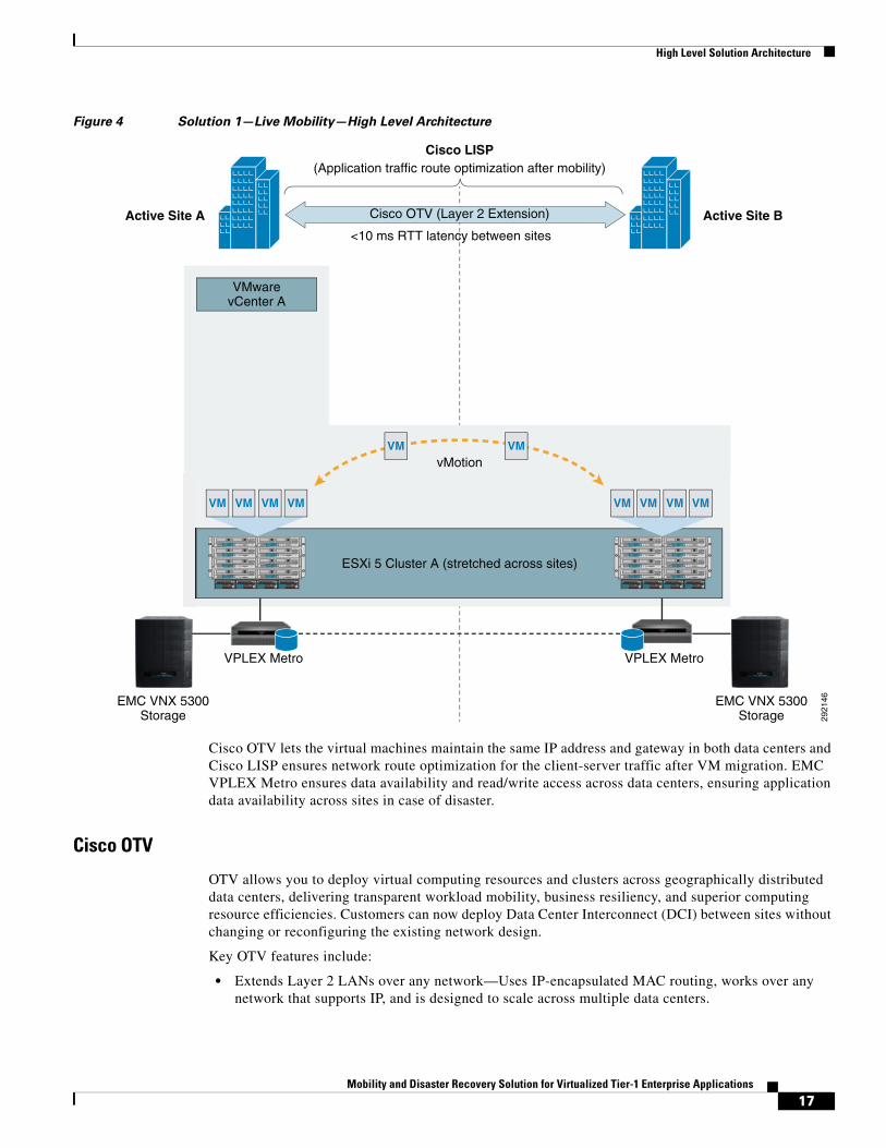
Architecture for Solution 1—Live Mobility Across Data CentersFigure 4 shows the logical architecture for the solution that enables virtualized applications live mobility across data centers with up to 10 ms RTT latency between them. This solution utilizes VMware vMotion to migrate a live workload to a remote data center.
Table 1 Software Versions for Solution Components
Software/Firmware Version
VMware vSphere 5.0
VMware SRM (for fully automated DR solution) 5.0
Cisco UCS 2.0 (1m)
Cisco Nexus 1000V 1.4a(4.2(1)SV1(4a))
Cisco Nexus 5020 5.0(2)N2(1a)
Cisco Nexus 7000 5.2(3a)
Cisco MDS 5.0 (4d)
EMC VNX 5300 5.31.0.5.502
EMC VPLEX Metro 5.0.1
EMC PowerPath /VE 5.7
EMC Unisphere V1.1.25.1.0129
EMC VSI Path Management—5.0.0.22
Storage Pool Management—5.0.0.43
Storage Viewer—5.0.0.64
Unified Storage Management—5.0.0.61
EMC RecoverPoint 3.4(SP2)
16Mobility and Disaster Recovery Solution for Virtualized Tier-1 Enterprise Applications
High Level Solution Architecture
Figure 4 Solution 1—Live Mobility—High Level Architecture
Cisco OTV lets the virtual machines maintain the same IP address and gateway in both data centers and Cisco LISP ensures network route optimization for the client-server traffic after VM migration. EMC VPLEX Metro ensures data availability and read/write access across data centers, ensuring application data availability across sites in case of disaster.
Cisco OTV
OTV allows you to deploy virtual computing resources and clusters across geographically distributed data centers, delivering transparent workload mobility, business resiliency, and superior computing resource efficiencies. Customers can now deploy Data Center Interconnect (DCI) between sites without changing or reconfiguring the existing network design.
Key OTV features include:
• Extends Layer 2 LANs over any network—Uses IP-encapsulated MAC routing, works over any network that supports IP, and is designed to scale across multiple data centers.
2921
46
Active Site A Cisco OTV (Layer 2 Extension)
(Application traffic route optimization after mobility)Cisco LISP
<10 ms RTT latency between sites
ESXi 5 Cluster A (stretched across sites)
vMotion
VPLEX Metro VPLEX Metro
EMC VNX 5300Storage
EMC VNX 5300Storage
Active Site B
UCS 5108
OK FAIL
! ResetConsole
! !UCS B200 M1
1 2
3 4
5 6
7 8
! ResetConsole
! !UCS B200 M1
! ResetConsole
! !UCS B200 M1
! ResetConsole
! !UCS B200 M1
! ResetConsole
! !UCS B200 M1
! ResetConsole
! !UCS B200 M1
! ResetConsole
! !UCS B200 M1
! ResetConsole
! !UCS B200 M1
OK FAIL OK FAIL OK FAIL
UCS 5108
OK FAIL
! ResetConsole
! !UCS B200 M1
1 2
3 4
5 6
7 8
! ResetConsole
! !UCS B200 M1
! ResetConsole
! !UCS B200 M1
! ResetConsole
! !UCS B200 M1
! ResetConsole
! !UCS B200 M1
! ResetConsole
! !UCS B200 M1
! ResetConsole
! !UCS B200 M1
! ResetConsole
! !UCS B200 M1
OK FAIL OK FAIL OK FAIL
VM VM VM VM
VM VM
VM VM VM VM
VMwarevCenter A
17Mobility and Disaster Recovery Solution for Virtualized Tier-1 Enterprise Applications
High Level Solution Architecture
• Simplifies configuration and operation—Enables seamless deployment over existing network without redesign, requires minimal configuration commands (as few as four), and provides single-touch site configuration for adding new data centers.
• Increases resiliency—Preserves existing Layer 3 failure boundaries, provides automated multihoming, and includes built-in loop prevention.
• Maximizes available bandwidth—Uses equal-cost multipathing and optimal multicast replication.
For detailed information on Cisco OTV, see: http://www.cisco.com/en/US/prod/switches/ps9441/nexus7000_promo.html.
Cisco LISP
LISP is a network architecture and set of protocols that implements a new semantic for IP addressing. LISP creates two namespace and uses two IP addresses: Endpoint Identifiers (EIDs), which are assigned to end-hosts, and Routing Locators (RLOCs), which are assigned to devices (primarily routers) that make up the global routing system. Performing this separation offers several advantages, including:
• Improved routing system scalability by using topologically-aggregated RLOCs
• Provider-independence for devices numbered out of the EID space (IP portability)
• Low-OPEX multi-homing of end-sites with improved traffic engineering
• IPv6 transition functionality
• IP mobility (EIDs can move without changing—only the RLOC changes!)
LISP is a simple, incremental, network-based implementation that is deployed primarily in network edge devices. It requires no changes to host stacks, DNS, or local network infrastructure and little to no major changes to existing network infrastructures.
For detailed information on Cisco LISP, see: http://www.cisco.com/en/US/prod/switches/ps9441/ps9402/nexus_7000.html.
Architecture for Solution 2—Fully Automated DRFigure 5 shows the architecture for the solution that enables fully automated DR for virtualized applications. This architecture is targeted towards virtualized applications that need a very efficient, fully automated DR solution with lowest possible RTO to protect against site-level failures. However, these applications do not have any requirement for live mobility across data centers. The applications are hosted on individual ESXi clusters on each site, with ESXi cluster on site A managed by vCenter Server on Site A and ESXi cluster on site B managed by a different vCenter server on Site B.
18Mobility and Disaster Recovery Solution for Virtualized Tier-1 Enterprise Applications

Detailed Solution Architecture
Figure 5 Solution 2—Fully Automated DR—High Level Architecture
Detailed Solution ArchitectureThis section highlights the detailed design for both the live mobility and fully automated DR solutions.
Solution 1—Live MobilityAs mentioned earlier in Architecture for Solution 1—Live Mobility Across Data Centers, this architecture is targeted towards customers looking to achieve live mobility for enterprise applications across data centers with no more than 10 ms. RTT latency between them and also require protection against site-level failure. The design details for this architecture are highlighted in this section.
2921
47
Active Site A Cisco OTV (Layer 2 Extension)
(Application traffic route optimization after DR)Cisco LISP
EMC RecoverPoint Remote Replication
ESXi 5 Cluster B ESXi 5 Cluster C
EMC VNX 5300Storage
EMC VNX 5300Storage
Active Site B
UCS 5108
OK FAIL
! ResetConsole
! !UCS B200 M1
1 2
3 4
5 6
7 8
! ResetConsole
! !UCS B200 M1
! ResetConsole
! !UCS B200 M1
! ResetConsole
! !UCS B200 M1
! ResetConsole
! !UCS B200 M1
! ResetConsole
! !UCS B200 M1
! ResetConsole
! !UCS B200 M1
! ResetConsole
! !UCS B200 M1
OK FAIL OK FAIL OK FAIL
UCS 5108
OK FAIL
! ResetConsole
! !UCS B200 M1
1 2
3 4
5 6
7 8
! ResetConsole
! !UCS B200 M1
! ResetConsole
! !UCS B200 M1
! ResetConsole
! !UCS B200 M1
! ResetConsole
! !UCS B200 M1
! ResetConsole
! !UCS B200 M1
! ResetConsole
! !UCS B200 M1
! ResetConsole
! !UCS B200 M1
OK FAIL OK FAIL OK FAIL
VM VM VM VM VM VM VM VM
VMwarevCenter A
VMwarevCenter B
AutomatedSite Failover
(SRM)
<10 ms RTT latency between sites
19Mobility and Disaster Recovery Solution for Virtualized Tier-1 Enterprise Applications

Detailed Solution Architecture
Cisco Unified Computing System
Eight (8) Cisco UCS B200M2 blade servers (four per site) were used in this architecture. Blade personality and configuration was standardized leveraging the Cisco UCS Service Profiles capability in UCS Manager. Each UCS blade was configured with six (6) 10G virtual NICs and two (2) 4GB FC adapters enabled by the Cisco UCS M81KR virtual interface card (VIC).
Figure 6 Solution 1—Live Mobility—Cisco UCS Details
Virtual Infrastructure Architecture
• The eight (8) Cisco UCS B200M2 blade servers (four at each site) enabled one stretched VMware ESXi cluster spanning both sites.
• One (1) vCenter Server on Site A to manage the entire virtual infrastructure.
• VMware ESXi cluster DRS rules, as shown in Figure 7, were used to make sure that all of the application VMs for SharePoint were on the same host of the stretched ESXi cluster to ensure that the SharePoint application VMs did not become split between the two sites.
2921
48
Site A
4x10GE 4x10GE
4x10GE 4x10GE
Cisco UCS 6100Fabric Interconnect
Cisco UCS 5100Blade Chassis with (2) B200M2 Blade Servers per Chassisand UCS M81KR VIC
Site B
4x10GE 4x10GE
4x10GE 4x10GE
Cisco UCS 6100Fabric Interconnect
Cisco UCS 5100Blade Chassis with (2) B200M2 Blade Servers per Chassisand UCS M81KR VIC
20Mobility and Disaster Recovery Solution for Virtualized Tier-1 Enterprise Applications

Detailed Solution Architecture
Figure 7 vSphere DRS Rules Details for Application VM Affinity
Virtual Networking
• Cisco Nexus 1000V virtual switch was leveraged for all the eight (8) hosts in the stretched ESXi cluster. Best practices for Cisco Nexus 1000V in a stretched cluster scenario were ensured per the details in the Cisco DCI design guide (http://www.cisco.com/en/US/docs/solutions/Enterprise/Data_Center/DCI/4.0/EMC/EMC_2.html#wp1261797).
• The Cisco Nexus 1000V Virtual Ethernet Module is a distributed virtual switch embedded in the hypervisor.
• The Cisco Nexus 1000V Virtual Supervisor Module (VSM) is a virtual machine that manages the networking policies and QoS for virtual machines in conjunction with the VEMs.
Truncated show module output from the active Cisco Nexus 1000V Virtual Supervisor Module is shown below.
metro-vsm# show moduleMod Ports Module-Type Model Status--- ----- -------------------------------- ------------------ ------------1 0 Virtual Supervisor Module Nexus1000V ha-standby2 0 Virtual Supervisor Module Nexus1000V active *3 248 Virtual Ethernet Module NA ok4 248 Virtual Ethernet Module NA ok5 248 Virtual Ethernet Module NA ok
21Mobility and Disaster Recovery Solution for Virtualized Tier-1 Enterprise Applications

Detailed Solution Architecture
6 248 Virtual Ethernet Module NA ok7 248 Virtual Ethernet Module NA ok8 248 Virtual Ethernet Module NA ok9 248 Virtual Ethernet Module NA ok10 248 Virtual Ethernet Module NA ok…Mod Server-IP Server-UUID Server-Name--- --------------- ------------------------------------ --------------------1 10.10.100.54 NA NA2 10.10.100.54 NA NA3 10.10.100.240 00fc3278-98e8-11df-0000-00000000002d dc2-esxi-c314 10.10.100.241 00fc3278-98e8-11df-0000-00000000001d dc2-esxi-c325 10.10.100.242 00fc3278-98e8-11df-0000-00000000002c dc2-esxi-c336 10.10.100.243 00fc3278-98e8-11df-0000-00000000001c dc2-esxi-c347 10.10.100.43 00000000-0000-0000-0000-00000000000b dc1-esxi-c348 10.10.100.41 00000000-0000-0000-0000-00000000001f dc1-esxi-c329 10.10.100.42 00000000-0000-0000-0000-00000000001e dc1-esxi-c3310 10.10.100.40 00000000-0000-0000-0000-00000000000e dc1-esxi-c31
The second section in the show command above lists IP addresses and names of the hypervisor hosting the VEM modules between the two sites.
The VSM manages the port-profile uplink and port group definitions for the Cisco Nexus 1000V. Figure 8 shows how these configurations relate.
Figure 8 VSM Ethernet port-profiles and vEthernet port-profiles Associated to the ESXi
Uplinks and the VM Port Connections to Which They Relate
VSMs are configured in redundant pairs, with a primary (active) and secondary (standby) relationship. These VSMs need to stay within the same group of geographically adjacent systems in the Metro (stretch) cluster, while not existing on the same hosts.
2921
57
VM
VM
VM
VM
ESXi
ESXi
ESXi
CiscoNexus 1000v
VSM
Port-Profile Ethernet (Host Uplink)
port-profile type ethernet VIC-VMDataNetwork-uplink vmware port-group switchport mode trunk switchport trunk allowed vlan 191 channel-group auto mode on mac-pinning no shutdown system vlan 191 state enabled
Port-Profile vEthernet (VM Interfaces)
port-profile type vethernet VIC-VMDataNetwork_10_10_101 vmware port-group switchport mode access switchport access vlan 191 no shutdown system vlan 191 state enabled
ESXi
22Mobility and Disaster Recovery Solution for Virtualized Tier-1 Enterprise Applications

Detailed Solution Architecture
Figure 9 Metro Stretch Cluster Representation—Shaded VSM is Standby, with Anti-Affinity Rules Keeping the VSMs
on Different ESXi Hosts
To address the VSM host group affinity to one side of the Metro cluster and anti-affinity between the VSM VMs, we implemented further DRS rules to prefer the VSMs to run on the hosts in the DC1 set of hosts and to prevent the VSMs from running on the same host.
Figure 10 DRS Rule for Keeping VSMs on DC1 Side
2921
58
ESXi
ESXi Hosts Virtual MachinesCisco UCS
ESXi
ESXi
ESXiVSM
VSM
Apps
App
App
Site A
Metro StretchCluster
Site B
ESXi
ESXi HostsVirtual Machines Cisco UCS
ESXi
ESXi
ESXiApp
23Mobility and Disaster Recovery Solution for Virtualized Tier-1 Enterprise Applications

Detailed Solution Architecture
Figure 11 DRS Rule for Anti-Affinity of the VSM VMs
Virtualized Enterprise and Infrastructure Applications
Table 2 highlights the details for the virtualized applications validated in this architecture.
In addition to these virtualized enterprise applications, Table 3 shows the supporting infrastructure virtual machines in the solution.
Table 2 Validated Virtualized Applications
Enterprise Application Virtual Machine Role and Quantity Operating System
SharePoint 2010 Front end Web servers (2) Windows Server 2008R2 Enterprise Edition
Application server (1)
SQL Server 2008 database (1)
Oracle 11g Oracle 11g standalone database (1) Red Hat Enterprise Linux 5.0
24Mobility and Disaster Recovery Solution for Virtualized Tier-1 Enterprise Applications
Detailed Solution Architecture
Physical Networking
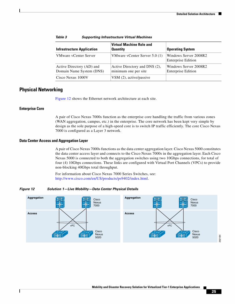
Figure 12 shows the Ethernet network architecture at each site.
Enterprise Core
A pair of Cisco Nexus 7000s function as the enterprise core handling the traffic from various zones (WAN aggregation, campus, etc.) in the enterprise. The core network has been kept very simple by design as the sole purpose of a high-speed core is to switch IP traffic efficiently. The core Cisco Nexus 7000 is configured as a Layer 3 network.
Data Center Access and Aggregation Layer
A pair of Cisco Nexus 7000s functions as the data center aggregation layer. Cisco Nexus 5000 constitutes the data center access layer and connects to the Cisco Nexus 7000s in the aggregation layer. Each Cisco Nexus 5000 is connected to both the aggregation switches using two 10Gbps connections, for total of four (4) 10Gbps connections. These links are configured with Virtual Port Channels (VPCs) to provide non-blocking 40Gbps total throughput.
For information about Cisco Nexus 7000 Series Switches, see: http://www.cisco.com/en/US/products/ps9402/index.html.
Figure 12 Solution 1—Live Mobility—Data Center Physical Details
Table 3 Supporting Infrastructure Virtual Machines
Infrastructure ApplicationVirtual Machine Role and Quantity Operating System
VMware vCenter Server VMware vCenter Server 5.0 (1) Windows Server 2008R2 Enterprise Edition
Active Directory (AD) and Domain Name System (DNS)
Active Directory and DNS (2), minimum one per site
Windows Server 2008R2 Enterprise Edition
Cisco Nexus 1000V VSM (2), active/passive
Aggregation
Access
Cisco Nexus7000
Cisco Nexus5020
vPC
Aggregation
Access
Cisco Nexus7000
Cisco Nexus5020
vPC
2921
84
25Mobility and Disaster Recovery Solution for Virtualized Tier-1 Enterprise Applications

Detailed Solution Architecture
Storage Networking Architecture
Figure 13 shows the details of the Fiber Channel storage networking architecture. A pair of Cisco MDS 9513s were leveraged at each site to provide dual fabric storage connectivity between Cisco UCS and EMC VPLEX Metro and VNX storage arrays.
• Cisco UCS 6100 fabric interconnect, EMC VNX Unified storage, and EMC VPLEX Metro devices at each site were connected in a dual fabric configuration.
• The two MDS switches at each site were trunked to the MDS switches on the other site to enable EMC VPLEX data replication and provide geographically distributed virtual volumes across both sites.
• SAN Zoning was performed per the Cisco and EMC best practices.
Figure 13 DR Solution 1—SAN Details
Storage Device Architecture
• Two distributed virtual volumes on EMC VPLEX Metro arrays were created using EMC VPLEX Management Console and presented as FC SAN LUNs to the ESXi hosts.
• The virtual volumes presented from the EMC VPLEX Metro were configured as multiple VMFS 5 datastores by the ESXi hosts.
• Distributed virtual volumes on VPLEX Metro were created using the FC SAN LUNs that were provisioned from the backend EMC VNX 5300 storage arrays using EMC Unisphere.
• EMC Best practices for VNX were followed to configure storage pools, FAST, and FAST Cache on the EMC VNX Unified storage arrays.
The FC SAN LUNS were created on the EMC VNX 5300 using the EMC Unisphere Management tool. EMC Unisphere is a simple, integrated experience for managing EMC VNX Family storage systems through both a storage and virtualization lens.
Compute
Storage
4x10GE
Fabric A
CiscoMDS 9513
CiscoUCS 6100FabricInterconnect
Cisco UCS B200M2Blade Servers
EMC VPLEX Metro
4x10GE 4x10GE
Compute
Storage
Dark Fiber - 10 ms RTT
Latency
CiscoMDS 9513
CiscoUCS 6100FabricInterconnect
Cisco UCS B200M2Blade Servers
EMC VPLEX Metro
4x10GE 4x10GE
2921
51
Fabric B
Site A Site B
4x10GE 4x10GE
EMC VNX 5300
4x10GE
EMC VNX 5300
26Mobility and Disaster Recovery Solution for Virtualized Tier-1 Enterprise Applications
Detailed Solution Architecture
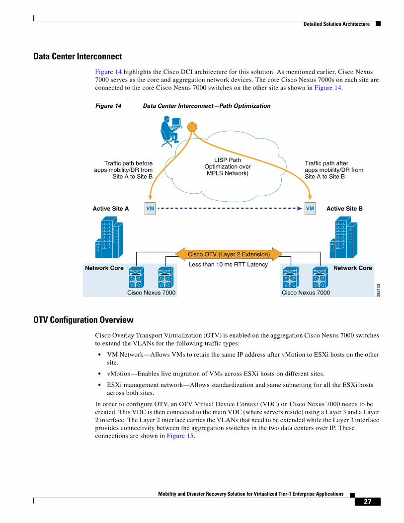
Data Center Interconnect
Figure 14 highlights the Cisco DCI architecture for this solution. As mentioned earlier, Cisco Nexus 7000 serves as the core and aggregation network devices. The core Cisco Nexus 7000s on each site are connected to the core Cisco Nexus 7000 switches on the other site as shown in Figure 14.
Figure 14 Data Center Interconnect—Path Optimization
OTV Configuration Overview
Cisco Overlay Transport Virtualization (OTV) is enabled on the aggregation Cisco Nexus 7000 switches to extend the VLANs for the following traffic types:
• VM Network—Allows VMs to retain the same IP address after vMotion to ESXi hosts on the other site.
• vMotion—Enables live migration of VMs across ESXi hosts on different sites.
• ESXi management network—Allows standardization and same subnetting for all the ESXi hosts across both sites.
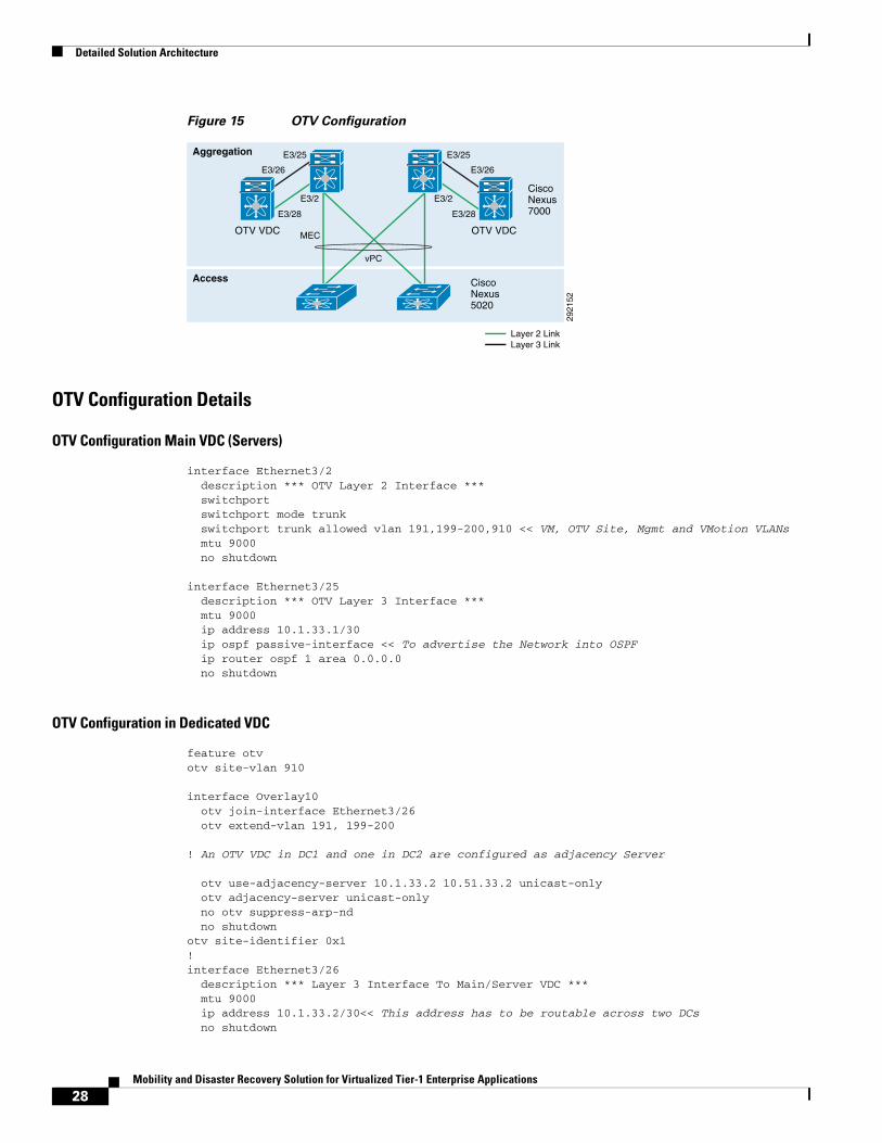
In order to configure OTV, an OTV Virtual Device Context (VDC) on Cisco Nexus 7000 needs to be created. This VDC is then connected to the main VDC (where servers reside) using a Layer 3 and a Layer 2 interface. The Layer 2 interface carries the VLANs that need to be extended while the Layer 3 interface provides connectivity between the aggregation switches in the two data centers over IP. These connections are shown in Figure 15.
Cisco Nexus 7000
Network Core
2921
53
Active Site A
Cisco OTV (Layer 2 Extension)
LISP PathOptimization overMPLS Network)
Less than 10 ms RTT Latency
Traffic path beforeapps mobility/DR from
Site A to Site B
Traffic path afterapps mobility/DR fromSite A to Site B
Cisco Nexus 7000
Network Core
Active Site BVM VM
27Mobility and Disaster Recovery Solution for Virtualized Tier-1 Enterprise Applications
Detailed Solution Architecture
Figure 15 OTV Configuration
OTV Configuration Details
OTV Configuration Main VDC (Servers)
interface Ethernet3/2 description *** OTV Layer 2 Interface *** switchport switchport mode trunk switchport trunk allowed vlan 191,199-200,910 << VM, OTV Site, Mgmt and VMotion VLANs mtu 9000 no shutdown
interface Ethernet3/25 description *** OTV Layer 3 Interface *** mtu 9000 ip address 10.1.33.1/30 ip ospf passive-interface << To advertise the Network into OSPF ip router ospf 1 area 0.0.0.0 no shutdown
OTV Configuration in Dedicated VDC
feature otvotv site-vlan 910
interface Overlay10 otv join-interface Ethernet3/26 otv extend-vlan 191, 199-200
! An OTV VDC in DC1 and one in DC2 are configured as adjacency Server
otv use-adjacency-server 10.1.33.2 10.51.33.2 unicast-only otv adjacency-server unicast-only no otv suppress-arp-nd no shutdownotv site-identifier 0x1!interface Ethernet3/26 description *** Layer 3 Interface To Main/Server VDC *** mtu 9000 ip address 10.1.33.2/30<< This address has to be routable across two DCs no shutdown
OTV VDCOTV VDC
Cisco Nexus5020
Cisco Nexus7000
vPC
E3/25
E3/2
E3/28
E3/26
MEC
2921
52
E3/25
E3/2
E3/28
E3/26
Layer 2 LinkLayer 3 Link
Aggregation
Access
28Mobility and Disaster Recovery Solution for Virtualized Tier-1 Enterprise Applications
Detailed Solution Architecture
!interface Ethernet3/28 description *** Layer 2 Interface To Main/Server VDC *** switchport switchport mode trunk switchport trunk allowed vlan 191,199-200,910 mtu 9000 no shutdown!ip route 0.0.0.0/0 10.1.33.1!
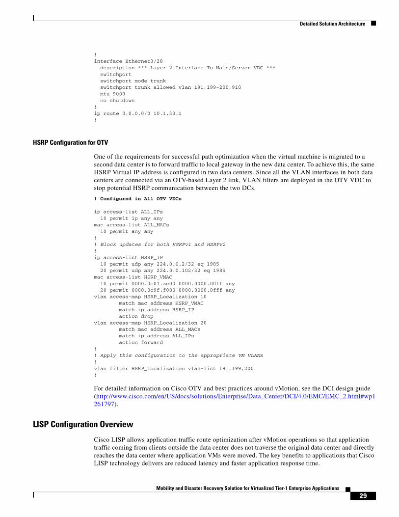
HSRP Configuration for OTV
One of the requirements for successful path optimization when the virtual machine is migrated to a second data center is to forward traffic to local gateway in the new data center. To achieve this, the same HSRP Virtual IP address is configured in two data centers. Since all the VLAN interfaces in both data centers are connected via an OTV-based Layer 2 link, VLAN filters are deployed in the OTV VDC to stop potential HSRP communication between the two DCs.
! Configured in All OTV VDCs
ip access-list ALL_IPs 10 permit ip any any mac access-list ALL_MACs 10 permit any any !! Block updates for both HSRPv1 and HSRPv2 !ip access-list HSRP_IP 10 permit udp any 224.0.0.2/32 eq 1985 20 permit udp any 224.0.0.102/32 eq 1985 mac access-list HSRP_VMAC 10 permit 0000.0c07.ac00 0000.0000.00ff any 20 permit 0000.0c9f.f000 0000.0000.0fff any vlan access-map HSRP_Localization 10 match mac address HSRP_VMAC match ip address HSRP_IP action dropvlan access-map HSRP_Localization 20 match mac address ALL_MACs match ip address ALL_IPs action forward!! Apply this configuration to the appropriate VM VLANs !vlan filter HSRP_Localization vlan-list 191,199,200!
For detailed information on Cisco OTV and best practices around vMotion, see the DCI design guide (http://www.cisco.com/en/US/docs/solutions/Enterprise/Data_Center/DCI/4.0/EMC/EMC_2.html#wp1261797).
LISP Configuration Overview
Cisco LISP allows application traffic route optimization after vMotion operations so that application traffic coming from clients outside the data center does not traverse the original data center and directly reaches the data center where application VMs were moved. The key benefits to applications that Cisco LISP technology delivers are reduced latency and faster application response time.
29Mobility and Disaster Recovery Solution for Virtualized Tier-1 Enterprise Applications

Detailed Solution Architecture
LISP in the solutions outlined above is configured on both the aggregation Cisco Nexus 7000s as well as at the branch. Some of the considerations for LISP deployment in the solution are:
• The server network should not be advertised to the remote branch using a routing protocol.
• The branch network should not be advertised to the aggregation Cisco Nexus 7000s using a routing protocol.
• The loopback addresses utilized as LISP endpoints should be advertised from the respective data centers so that the branch can route to the data center directly.
• Aggregation Cisco Nexus 7000s are configured as both ITR and ETR (also known as xTR).
• OTV VDC on one of the aggregation Cisco Nexus 7000 in each data center is used as a MAP server.
Some of the addresses used in the LISP configuration are shown in Figure 16.
Figure 16 LISP Configuration Parameters
LISP Configuration Details
LISP Map Server/Resolver Configuration
Configuration in OTV VDC on one of the aggregation 7000s in each data center (for redundancy):
feature lisp!vrf context lisp-map!interface loopback1000<< Used as Map Server Address - unique in each DC ip address 1.1.1.101/32!interface loopback1001<< Used as Resolver Address - same in both DCs ip address 3.3.3.101/32!ip lisp map-resolver
AggregationNexus 7000 OTV VDC
(Map Server)
Active Site A
2921
54
MPLS Network
172.17.4.0/24
Data Center Servers10.10.101.0/26
Loopback172.17.200.1
Loopback1.1.1.101
Loopback1.1.1.2
Loopback1.1.1.1
AggregationNexus 7000OTV VDC
(Map Server)
Active Site B
Loopback2.2.2.101
Loopback2.2.2.2
Loopback2.2.2.1
30Mobility and Disaster Recovery Solution for Virtualized Tier-1 Enterprise Applications

Detailed Solution Architecture
ip lisp map-serverip lisp alt-vrf lisp-map!lisp site Branch eid-prefix 172.17.4.0/24 accept-more-specifics authentication-key 3 e1631301f8be20aa!lisp site DC eid-prefix 10.10.0.0/16 accept-more-specifics authentication-key 3 e1631301f8be20aa!
LISP Configuration on 7000 xTR
Configuration in main VDC (where server network exists):
feature lisp!interface loopback1000 ip address 1.1.1.1/32 ip router ospf 1 area 0.0.0.0!lisp smr-locatorsip lisp itr-etr!! 1.1.1.1/2 are the addresses in DC1; 2.2.2.1/2 are the addresses in DC2 !ip lisp database-mapping 10.10.0.0/16 1.1.1.1 priority 1 weight 10ip lisp database-mapping 10.10.0.0/16 1.1.1.2 priority 1 weight 10ip lisp database-mapping 10.10.0.0/16 2.2.2.1 priority 1 weight 10ip lisp database-mapping 10.10.0.0/16 2.2.2.2 priority 1 weight 10!ip lisp itr map-resolver 3.3.3.101ip lisp etr map-server 1.1.1.101 key 3 e1631301f8be20aaip lisp etr map-server 2.2.2.101 key 3 e1631301f8be20aa!lisp dynamic-eid server_ten10!! All the Oracle and SharePoint servers were in lower half of 10.10.101.0/24 subnet ! making it easier to define a more specific /25 subnet in database-mapping as per ! LISP requirements ! database-mapping 10.10.101.0/25 1.1.1.1 priority 1 weight 10 database-mapping 10.10.101.0/25 1.1.1.2 priority 1 weight 10 map-notify-group 239.1.1.1!interface Vlan191 no shutdown mtu 9000 description *** Server Subnet *** no ip redirects ip address 10.10.101.2/24 ip ospf passive-interface ip router ospf 1 area 0.0.0.0 lisp mobility server_ten10 lisp extended-subnet-mode hsrp version 2 hsrp 191 authentication text c1sc0 preempt delay minimum 180 priority 105 timers 1 3
31Mobility and Disaster Recovery Solution for Virtualized Tier-1 Enterprise Applications

Detailed Solution Architecture
ip 10.10.101.1!
LISP Configuration on Branch
interface Loopback1000 ip address 172.17.200.1 255.255.255.255!interface LISP0!router lisp loc-reach-algorithm rloc-probing database-mapping 172.17.4.0/24 172.17.200.1 priority 1 weight 100 ipv4 itr map-resolver 3.3.3.101 ipv4 itr ipv4 etr map-server 2.2.2.101 key SMT ipv4 etr map-server 1.1.1.101 key SMT ipv4 etr!
Solution 2—Fully Automated DRAs mentioned earlier in Architecture for Solution 2—Fully Automated DR, this architecture is targeted towards applications that have a requirement for a DR solution with the lowest possible RTO but do not require live mobility.
The design details for this architecture are highlighted in this section. Note that the same physical setup was used for both solution 1 and 2 and the differences are highlighted in this section as required. OTV and LISP configuration for this solution are also the same as described in the last section.
Cisco Unified Computing System
Eight Cisco UCS B200M2 blade servers (four per site) were leveraged in this architecture. Blade personality and configuration was standardized using the Cisco UCS Service Profiles capability in UCS Manager. Each UCS blade was configured with six 10GbE virtual NICs and two 4GB FC adapters enabled by a Cisco UCS M81KR virtual interface card (VIC).
Figure 17 Solution 2— Fully Automated DR—UCS Details
Virtual Infrastructure Architecture
• The four Cisco UCS B200M2 blade servers at each site were part of an VMware ESXi cluster, i.e., total of two ESXi clusters, one at each site.
2921
48Site A
4x10GE 4x10GE
4x10GE 4x10GE
Cisco UCS 6100Fabric Interconnect
Cisco UCS 5100Blade Chassis with (2) B200M2 Blade Servers per Chassisand UCS M81KR VIC
Site B
4x10GE 4x10GE
4x10GE 4x10GE
Cisco UCS 6100Fabric Interconnect
Cisco UCS 5100Blade Chassis with (2) B200M2 Blade Servers per Chassisand UCS M81KR VIC
32Mobility and Disaster Recovery Solution for Virtualized Tier-1 Enterprise Applications
Detailed Solution Architecture
• Separate vCenter servers managed ESXi clusters in each of the sites.
• Each site had its own vCenter SRM server with the RecoverPoint SRA software installed to enable storage failover during disaster.
• VMFS datastores hosting the VMs were created and mapped directly from the EMC VNX 5300 storage using the EMC VSI vCenter plug-in.
Virtual Networking
• Separate Cisco Nexus 1000V virtual switches were leveraged for the ESXi clusters on each site. Best practices for Cisco Nexus 1000V deployment and configuration were ensured by following the procedures in the Cisco Nexus 1000V guide (http://www.cisco.com/en/US/prod/collateral/switches/ps9441/ps9902/white_paper_c11-558242.html).
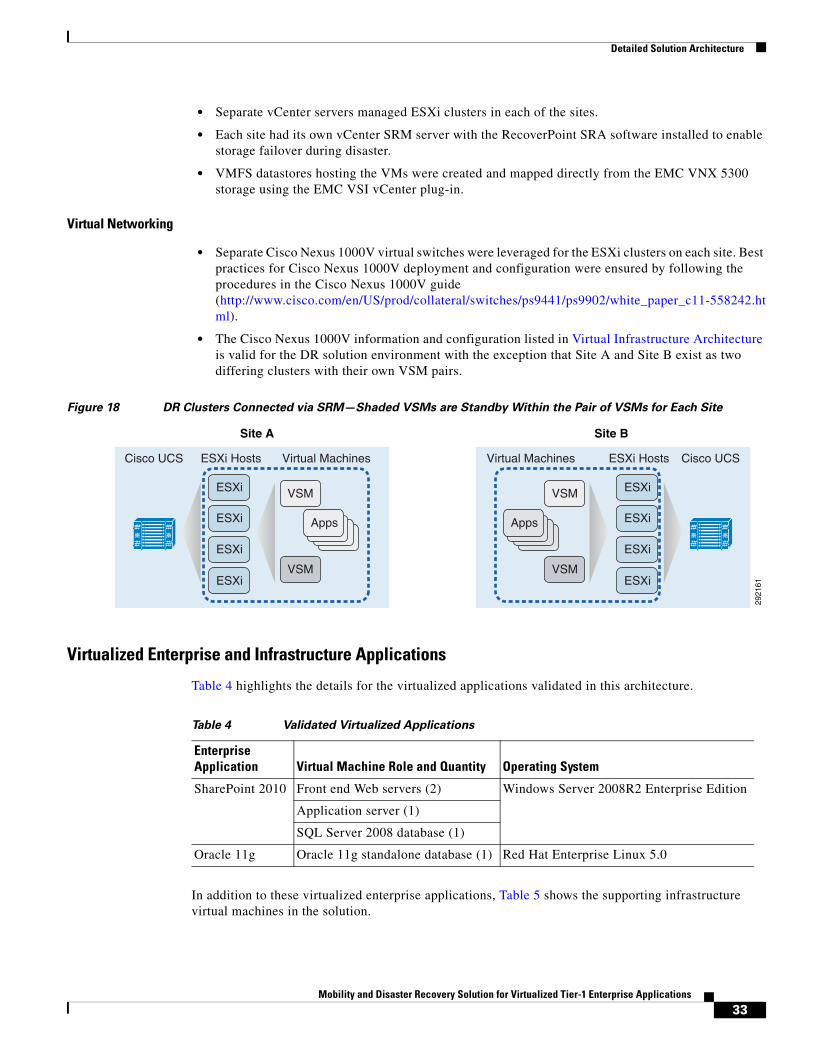
• The Cisco Nexus 1000V information and configuration listed in Virtual Infrastructure Architecture is valid for the DR solution environment with the exception that Site A and Site B exist as two differing clusters with their own VSM pairs.
Figure 18 DR Clusters Connected via SRM—Shaded VSMs are Standby Within the Pair of VSMs for Each Site
Virtualized Enterprise and Infrastructure Applications
Table 4 highlights the details for the virtualized applications validated in this architecture.
In addition to these virtualized enterprise applications, Table 5 shows the supporting infrastructure virtual machines in the solution.
2921
61
ESXi
ESXi Hosts Virtual MachinesCisco UCS
ESXi
ESXi
ESXiVSM
VSM
Apps
Site A Site B
ESXi
ESXi HostsVirtual Machines Cisco UCS
ESXi
ESXi
ESXiVSM
VSM
Apps
Table 4 Validated Virtualized Applications
Enterprise Application Virtual Machine Role and Quantity Operating System
SharePoint 2010 Front end Web servers (2) Windows Server 2008R2 Enterprise Edition
Application server (1)
SQL Server 2008 database (1)
Oracle 11g Oracle 11g standalone database (1) Red Hat Enterprise Linux 5.0
33Mobility and Disaster Recovery Solution for Virtualized Tier-1 Enterprise Applications

Detailed Solution Architecture
Physical Networking
The same physical network infrastructure (core/aggregation/access) that was used for validating Solution 1—Live Mobility was used for this Fully Automated DR Solution. For detailed information on physical networking architecture, see Physical Networking.
Storage Networking Architecture
Figure 19 shows the details of the FC storage networking at both sites. A pair of Cisco MDS 9513 SAN switches were leveraged at each site to provide dual fabric storage connectivity between the Cisco UCS and EMC VNX storage. Note that this is the same hardware infrastructure that was used for solution 1, live mobility. Note that the EMC VPLEX devices and ISL connectivity between the MDS 9513 switches on both sites were not required in solution 2.
Figure 19 Solution 2— Fully Automated DR—SAN Details
Table 5 Supporting Infrastructure Virtual Machines
Infrastructure ApplicationVirtual Machine Role and Quantity Operating System
VMware vCenter Server VMware vCenter Server 5.0 (2) Windows Server 2008R2 Enterprise Edition
Active Directory and DNS Active Directory and DNS (2), minimum one per site
Windows Server 2008R2 Enterprise Edition
Cisco Nexus 1000V VSM (2), active/passive
VMware vCenter SRM Server VMware vCenter SRM Server (total 2, 1 per site)
Windows Server 2008R2 Enterprise Edition
Compute
Storage
4x10GE
Fabric A
CiscoMDS 9513
CiscoUCS 6100FabricInterconnect
Cisco UCS B200M2Blade Servers
4x10GE 4x10GE
Compute
Storage
4x10GE
CiscoMDS 9513
CiscoUCS 6100FabricInterconnect
Cisco UCS B200M2Blade Servers
EMC RcoverPointEMC RecoverPoint
4x10GE 4x10GE
2921
55
Fabric B
Site A Site B
4x10GE4x10GE
EMC VNX 5300EMC VNX 5300
34Mobility and Disaster Recovery Solution for Virtualized Tier-1 Enterprise Applications

Solution Validation
Storage Architecture
• VMFS datastores hosting the application and infrastructure VMs were created using the EMC VSI plug-in directly from within vCenter. The EMC VSI plug-in ensured the creation of FC SAN LUNs on the backend VNX 5300 storage arrays.
• EMC best practices were followed to configure storage pools, FAST, and FAST Cache on the EMC VNX Unified storage arrays.
VMFS datastores hosting the application and infrastructure VMs were created using the EMC VSI for VMware vSphere: Unified Storage Management Plug-in. EMC Virtual Storage Integrator (VSI) is a free VMware vCenter plug-in available to all VMware users with EMC storage in their environment. Users can create datastores (block or file) directly from the vCenter management console.
Data Center Interconnect
For detailed information on OTV and LISP configuration, see Data Center Interconnect.
Special Considerations for Active Directory and Domain Name System This section describes details of the AD/DNS architecture and special considerations when validating live mobility, DR testing, site failover, and site failback.
• AD/DNS architecture plays a very important role in the successful failover, DR testing, and failback scenarios. An improper architecture can result in a USN rollback scenario with a corrupt AD database. Refer to http://support.microsoft.com/kb/875495 for more information about the AD issues.
• One AD/DNS virtual server was configured at each site to provide authentication and name resolution services. This also allowed AD/DNS high availability and protection against site-level failures.
• AD/DNS VM at each site was cloned and attached “only” to the SRM test bubble network before the application VMs were powered on. After AD/DNS server power on in the test network, five Flexible Single Master Operations (FSMO) roles in the AD forest must be seized as per the procedure described in the Microsoft KB: http://support.microsoft.com/kb/255504. The five roles are Schema master, Domain naming master, RID master, PDC emulator, and Infrastructure master.
• For the real DR failover scenario (simulated by VMware SRM), the AD cloning process is not required. In the SRM failover scenario, the existing AD server at the recovery site provides the name resolution and AD services. However, the five FSMO roles must be seized per the procedure described in the Microsoft KB: http://support.microsoft.com/kb/255504.
Solution ValidationThis section provides details of the validation for both solutions—live mobility and fully automated DR—described in this white paper.
35Mobility and Disaster Recovery Solution for Virtualized Tier-1 Enterprise Applications

Solution Validation
Solution 1—Live MobilityvMotion was initiated simultaneously for the four SharePoint application VMs (app1, wfe1, wfe2, sql), and the Oracle VM. Migration of these application VMs completed within a minute between DC1 and DC2 and application response experienced minimal lapses. Since Layer 2 VLANs used by VMs as well as VMWare were extended using OTV, IP addresses remained the same during this move. The gateway addresses in both data centers were configured to be the same HSRP addresses. This helped with local forwarding of return traffic. Traffic from the branch to the data center used the optimized path provided by LISP.
Figure 20 vMotion Times for Application VMs Migrating Across the Metro Stretch Cluster
Solution 2—Fully Automated DRSRM was invoked by running the recovery plan for DC1 to recover to DC2. VMs do not migrate in a live state for SRM recovery, so application availability received a short duration outage. VMs were disassociated from their active state in DC1 and powered up in DC2 with an application outage of approximately seven minutes. VMs were brought back up in DC2 using their same IPs and DNS entries, which was made possible by the LAN extension capabilities provided by OTV. Since invoking the recovery plan simulated a partial failure of the data center, routing for these VMs was dynamically changed through LISP in this migration, so the path was automatically optimized for DC2.
Figure 21 Site Recovery Manager with a Recovery Plan Completed for Both Application Sets
(SharePoint and Oracle) Between DC1 and DC2
VerificationThe following show commands and screen captures provide verification of various components. The output shown below is sample output for the two solutions and is specific to the scenario described in this document. In a real customer environment, the traffic verification technology and tools used can be different and unique to the customer’s environment.
36Mobility and Disaster Recovery Solution for Virtualized Tier-1 Enterprise Applications

Solution Validation
Verification of Extended VLAN Using OTV
Figure 22 shows the network connectivity in both data centers (mirrored).
Figure 22 Data Center Connectivity
OTV configuration can be verified by show commands in the OTV VDC on Cisco Nexus 7000. Local virtual machines are connected via access layer Cisco Nexus 5000s over Port Channel 45. Virtual machines in the remote data center are connected via OTV and hence are known via interface Ethernet 3/2. This can be easily verified by looking at the mac address-table.
OTV VDC
DC1-N7K-1-OTV# show otv adjacency
!! This command shows adjacency built with other 3 Cisco Nexus 7000s!Overlay Adjacency database
Overlay-Interface Overlay10 :Hostname System-ID Dest Addr Up Time StateDC1-N7K-2-OTV 0024.f716.4343 10.1.33.2 1d19h UP DC2-N7k-1-OTV 0023.ac64.73c3 10.51.33.2 1d21h UP DC2-N7k-2-OTV 0023.ac64.7443 10.51.33.6 1d21h UP
DC1-N7K-1-OTV# show otv route
!! This command shows whether a MAC was learnt from local or overlay ! interface !OTV Unicast MAC Routing Table For Overlay10
VLAN MAC-Address Metric Uptime Owner Next-hop(s)---- -------------- ------ -------- --------- ----------- 191 0000.0c9f.f0bf 1 00:00:03 site Ethernet3/28 191 000d.eccf.e532 1 1d19h site Ethernet3/28 191 000d.ecd0.4170 1 1d19h site Ethernet3/28 191 000d.ecd0.7b31 42 1d21h overlay DC2-N7k-2-OTV 191 0023.ac64.73c2 42 1d21h overlay DC2-N7k-2-OTV<SNIP>
OTV VDCOTV VDC
Cisco Nexus5020
Cisco Nexus7000
vPC
E3/25
E3/2
E3/28
E3/26
Po45
2921
85
E3/25
E3/2
E3/28
E3/26
Layer 2 LinkLayer 3 Link
Aggregation
Access
37Mobility and Disaster Recovery Solution for Virtualized Tier-1 Enterprise Applications
Solution Validation
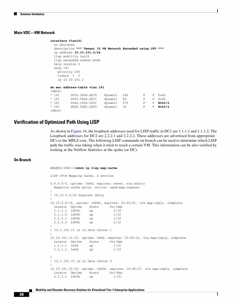
Main VDC—VM Network
interface Vlan191 no shutdown description *** Tenant 10 VM Network Extended using OTV *** ip address 10.10.101.2/24 lisp mobility ten10 lisp extended-subnet-mode hsrp version 2 hsrp 191 priority 105 timers 1 3 ip 10.10.101.1
sh mac address-table vlan 191<SNIP>* 191 0050.56b8.6b70 dynamic 240 F F Po45* 191 0050.56b8.6b71 dynamic 60 F F Po45* 191 00a0.c90a.0201 dynamic 270 F F Eth3/2* 191 d0d0.fdd3.6093 dynamic 30 F F Eth3/2<SNIP>
Verification of Optimized Path Using LISP
As shown in Figure 16, the loopback addresses used for LISP traffic in DC1 are 1.1.1.1 and 1.1.1.2. The Loopback addresses for DC2 are 2.2.2.1 and 2.2.2.2. These addresses are advertised from appropriate DCs to the MPLS core. The following LISP commands on branch can be used to determine which LISP path the traffic was taking when it tried to reach a certain VM. This information can be also verified by looking at the Netflow Statistics at the spoke (or DC).
On Branch
BRANCH-3945-1#show ip lisp map-cache LISP IPv4 Mapping Cache, 4 entries
0.0.0.0/0, uptime: 5w0d, expires: never, via static Negative cache entry, action: send-map-request!! 10.10.0.0/16 Supernet Entry !10.10.0.0/16, uptime: 1d00h, expires: 23:59:01, via map-reply, complete Locator Uptime State Pri/Wgt 1.1.1.1 1d00h up 1/10 1.1.1.2 1d00h up 1/10 2.2.2.1 1d00h up 1/10 2.2.2.2 1d00h up 1/10 !! 10.1.101.11 is in Data Center 1 !10.10.101.11/32, uptime: 3w6d, expires: 23:59:12, via map-reply, complete Locator Uptime State Pri/Wgt 1.1.1.1 3w6d up 1/10 1.1.1.2 3w6d up 1/10
!! 10.1.101.33 is in Data Center 2 !10.10.101.33/32, uptime: 1d00h, expires: 16:45:57, via map-reply, complete Locator Uptime State Pri/Wgt 2.2.2.1 1d00h up 1/10
38Mobility and Disaster Recovery Solution for Virtualized Tier-1 Enterprise Applications

Solution Validation
2.2.2.2 1d00h up 1/10
On DC1 7K-1
DC1-N7K-1-vdcA# show ip lisp map-cache !! 172.17.200.1 is the Loopback used for LISP on Branch ! 172.17.4.0/24 is the Branch LAN !
LISP IP Mapping Cache for VRF "default" (iid 0), 3 entries* = Locator data counters are cumulative across all EID-prefixes
172.17.4.0/24, uptime: 1d00h, expires: 23:03:24, via map-reply, auth Locator Uptime State Priority/ Data Control Weight in/out in/out 172.17.200.1 1d00h up 1/100 0/40309 2/0
Test Tool Traffic
Traffic graphs captured while running some of these tests are shown below to give reader an idea of traffic fluctuations when these tests were performed.
Visual Studio Traffic for SharePoint
Figure 23 Visual Studio Key Indicators Graph—Lapse in Pages/Sec. Represent vMotion from
DC1 to DC2 Followed by a Return vMotion from DC2 to DC1 Across the Stretch Metro
Cluster
39Mobility and Disaster Recovery Solution for Virtualized Tier-1 Enterprise Applications

Conclusion
Swing Bench Traffic for Oracle
Figure 24 Swing Bench (Oracle Transaction Simulation Tool) View of Round Trip DC1 to DC2
vMotion with Shorter X-axis Representing Approximately a Two Minute Time Slice
View
ConclusionTo meet ever growing IT infrastructure needs and ensure business continuity in case of a site-level disaster, it is critical to have live mobility and a fully automated DR process for virtualized enterprise applications across data centers.
This white paper provided key design considerations for building a robust live mobility and fully automated DR solution for virtualized applications leveraging innovative technologies from Cisco, EMC, and VMware.
Live mobility for virtualized applications across data centers allows IT organizations to efficiently meet various operational needs such as data capacity expansion, seamless migrations, disaster avoidance, etc.
Fully automated DR allows customers to protect their mission critical enterprise applications against site-level disasters and ensure business continuance. Key advantage of this solution over manual, runbook style DR process execution is minimum downtime with lowest RTO. This is extremely critical for next generation cloud solutions required to host 100s to 1000s of virtualized applications on the same shared infrastructure.
For both the Live Mobility and Fully Automated DR solutions discussed in this white paper, technologies worked together in a seamless manner. The data was replicated to both the data centers without any user intervention and there was no need to change the IP addresses or routing after applications were migrated or brought up in the remote data center.
The design presented in this white paper is highly modular, so that environments with differing requirements have the flexibility to deploy either or both the live mobility and fully automated DR solution.
For additional information, contact your Cisco, EMC, or VMware sales representatives.
40Mobility and Disaster Recovery Solution for Virtualized Tier-1 Enterprise Applications