modal strain energies in cosmic - nasa · modal strain energies in cosmic nastran b. d. snyder and...
TRANSCRIPT

N 8 9 - 22 95 5 MODAL STRAIN ENERGIES IN COSMIC NASTRAN
B. D. Snyder and V. B. Venkayya Flight Dynamics Laboratory
Wright Patterson AFB
SUMMARY
A computer program was developed to take a NASTRAN output file from a normal modes analysis and calculate the modal strain energies of selected elements. The FOR- TRAN program can determine the modal strain energies for CROD, CBAR, CELAS, CTRMEM, CQDMEM2, and CSHEAR elements. Modal strain energies are useful in estimating damping in structures.
IN TROD U CTIO N
This work was initiated to predict damping in a large passively damped truss structure. The twelve meter truss structure is currently undergoing modal testing in preparation for controls experiments. An estimate of the total damping in the structure is needed for the controls experiments.
The starting point for the computer program was the ANALYZE program (ref. 1). First, the information needed for the strain energies was extracted from a NASTRAN output file (ref. 2). Element information is extracted from the echo of the bulk data and eigenvector information is extracted from the eigenvector tables for each mode. The element stiffness matrices are formed and then multiplied by the appropriate element eigenvector and its transpose and divided by two. The result is the element strain energies for a given mode. With this information, the modal strain energy method can be used to predict the damping in a viscoelastically damped structure. COSMIC NASTRAN can output element strain energies but only for static analyses. To predict the structural damping, the element modal strain energies for a normal modes analysis have to be found.
SYMBOLS
w, = x displacements in the plane of the plate in the local coordinate system
wy = y displacements in the plane of the plate in the local coordinate system
a1 , bl , c1, a2, b2, c2 = six undetermined coefficients
q, yl , . . . , x3, y3 = coordinates of the 3 nodes of the triangle in the local coordinate system
rj = shape matrix
0 = stress vector 5 = strain vector
*
363
https://ntrs.nasa.gov/search.jsp?R=19890013584 2018-05-30T08:01:15+00:00Z

G = shear modulus
E = modulus of elasticity
= element stiffness matrix
f = element eigenvector for the rth mode
ELEMENT FORMULATION
As mentioned previously, the formulation of the elements comes from the ANALYZE program. The element stiffness matrices are exactly the same as the COSMIC NAS- TRAN formulation for the CELAS, CBAR, and CROD elements. The formulation for the CTRMEM and CQDMEM2 elements is slightly different than COSMIC NASTRAN. The CSHEAR formulation is very different from the COSMIC NASTRAN formulation. The basis for the derivation of the shear panel is empirical but accurately constructed finite el- ement models produce satisfactory results. The modal strain energy program will produce good results if the shear panel planform is as close to rectangular as possible. The less skew- ing of the element, the better the results will be.
The triangular membrane element used in this program is a constant strain plate element. The quadrilateral membrane and shear elements are constructed of four (non- overlapping) of the constant strain triangular membrane elements mentioned above. The elements are assumed to be flat plates which means the warping in the elements is ignored. The elements have a fictitious interior node which is later removed by static condensation. Only shear energy is considered in the stiffness of the shear element where the quadrilateral membrane element considers all the energy in the element.
Since the triangular membrane element is the basis for all the other plate elements in this program, the derivation will be given along with how these triangle elements are used to formulate the quadrilateral and shear elements. The linear displacement field in the triangular element can be represented by
wy = a25 + b2y + e2
or in matrix form
The six unknown coefficients can be uniquely determined by the six boundary conditions
364

at the nodes.
(4)
0 0 0 1 X 2 Y 2 \ o 0 0 I x3 93
The inversion of the partitioned diagonal matrix involves simply the inversion of the component matrix. The shape matrix q I is given by
where the matrix g is given by
) a:= ( O O O x y l x y l 0 0 0
The coordinate matrix X is given by
From linear strain-displacement relations, the strains can be written as
LIW
d X awz + 2 =, bl + a2 czy =
From the principle of virtual work, the elements of the member stiffness matrix can be
where and & j ) are the stress and strain matrices corresponding to the unit dis- placement modes explained in equation 8. Since the linear displacement relation implies constant strain, the integral in equation 12 can be replaced by the volume of the element:
365

where 1x1 is the determinant of the nodal coordinate matrix which represents twice the area of the element and t is the thickness of the element. Finally, the stiffness matrix of the triangular membrane element is given by
Equation 14 gives the formulation for the stiffness matrix of the triangular membrane ele- ments. What follows, is how four of these triangular elements are used to construct quadri- lateral membrane and shear elements.
The stiffness matrix of the quadrilateral membrane element is determined by breaking it into four component triangles. The fictitious node in the quadrilateral is located by averaging the coordinates of the four nodes as follows
51 + 52 + 53 + x4 4 x5 =
91 + Y2 + Y3 + Y4 4 Y5 =
The stiffness of the four triangles can then be computed by equation 14. Addition of the four stiffness matrices gives a 10 x 10 stiffness matrix with two degrees of freedom included for the fifth node. The force displacement relations of the five node quadrilateral are written as
R Q = kQ rQ (17)
where the subscript refers to the quadrilateral element with five nodes. Equation 17, partitioned to isolate the degrees of freedom of the fifth node can be written as
Equation 18 can be written as two separate equations
R, = k 1 J T I + k I J 1 r11 (19)
R I I = k 1 I J 5 + kI1,II r11 (20)
Since the fifth node doesn't actually exist in the original model, no external forces can be applied to this node. This condition gives
Substitution of equation 21 in equation 19 gives
R, = (&I, , - k I J 1 &,:I le11,I) r ,
366

From equation 22 the stiffness matrix of the original quadrilateral membrane element can be written as
IC = IC11 - ICIJI I C , ' , , ICIIJ (23)
The shear element is also composed of four triangular elements however, the stiffness matrices of the component triangles are determined by considering only the shear strain energy (equation 13).
(24) 1 (4 ( j ) 2 - k;j = - (XI t f zy Gczy
MODAL STRAIN ENERGY PROGRAM
The program starts by reading in all the information it needs from a NASTRAN output file for a normal modes analysis. As the program is set up, it can handle 1,000 of any one type of element for a total of 6,000 elements. A total of 100 materials can be specified but only isotropic materials specified on MAT1 cards are currently accounted for. The model can have 100 properties for any one element type for a total of 600 property cards. These limits can easily be expanded by changing the dimensions of the arrays in the code. The CELAS elements (CELAS1 or CELAS2) must be grounded (fixed) at one end with the other end connected to the structure. There are two ways to do this, one is to leave the sec- ond grid point of the CELAS card and its component blank or the second way is to specify a second grid point and component and then fix the second grid point component with an SPC card.
The next step in determining the modal strain energies is to calculate the element stiffness matrices. Using the equations derived above and equations for the CELAS, CBAR, and CROD elements, the stiffness matrices are generated. After this the eigenvector for the current element is extracted from the eigenvector table for a given mode. Then the following equation is used to determine the element modal strain energies for the given mode
Element Modal Strain Energy = -qStkqY
The equation is used for each element for every mode printed in the NASTRAN normal modes analysis.
After the element strain energies are calculated, they are printed in an easy to read format. The modal strain energy program prints out the following quantities for each mode: element ID number (EID), element type (CBAR, CELAS, CROD, CTRMEM, CSHEAR, or CQDMEM2), element strain energy (in consistent units), percent element strain energy of the entire structure, sum of the total element strain energy for each element type, and the total element strain energy for the entire structure. The program also prints one- half the generalized stiffness from the NASTRAN output file as a check. One-half the generalized stiffness should equal the total strain energy for the entire structure.
(25 ) 1 2 - -
APPLICATIONS
Viscoelastic materials are seeing widespread use to suppress vibrations in all types of
367
structures. The ability of viscoelastic materials to passively damp vibrations in lightweight structures is well documented. Modal strain energies are useful in estimating the damping in this type of structure. The approach used to predict the modal damping (loss) factors for each mode of the structure is called the modal strain energy method. It states that the ratio of structural loss factor to viscoelastic material loss factor for a given mode of vibration can be estimated as the ratio of elastic strain energy in the viscoelastic to total elastic strain energy in the entire structure when it deforms into the particular undamped mode shape (ref. 3) . Mathematically this can be stated as
where
71 = loss factor for the r’th mode of the composite structure
vu = material loss factor for the viscoelastic material
V,’ = elastic strain energy stored in the viscoelastic material when the structure deforms in its r’th undamped mode shape
V,’ = elastic strain energy of the entire composite structure in the r’th mode shape
Computing the undamped mode shapes of the composite structure with the viscoelastic material treated as if it were purely elastic with a real stiffness modulus, the right hand side of equation 26 is calculated as
where
tr = r’th mode shape vector
ti = subvector formed by deleting from r j all entries not corresponding to motion of - nodes of the 8 t h viscoelastic element
= element stiffness matrix of the B’th viscoelastic element
K = stiffness matrix of the entire composite structure
n = number of viscoelastic elements in the model
Combining equations 26 and 27 you get (ref. 4)
This equation states that if you create a NASTRAN all elements included except damper elements, and
model of the damped structure with then run a normal modes analysis,
368
you have all the information needed to get the structural loss factor. After you make the NASTRAN run, you run the output t,hrough the element modal strain energy program which gives you the percentages of element strain energy to total strain energy for the entire structure. The percentages for the elements that actually possess viscoelastic damping are multiplied by that particular elements material loss factor. These quantities are then summed to give the loss factor for the entire structure.
EXAMPLE PROBLEMS
Three example problems were used to demonstrate the ability of the element strain energy program to accurately output the element modal strain energies. The first problem is a rectangular wing box and it is shown broken up into its numbered elements in figure 1. The rectangular wing box consists of quadrilateral membrane elements for the inboard top and bottom skins, triangular membrane elements for the outboard top and bottom skins, bar elements for the outboard posts, rod elements for all other posts, shear elements for all the ribs and spars, elastic elements provide the inboard top skin attachment points with the inboard bottom skin points rigidly fixed. The strain energy outputs for the second mode of this model are given in table I. This model contains all the element types the strain energy program is capable of handling. Comparing the total structural strain energy with the value'for one-half the generalized stiffness shows that the two are in agreement.
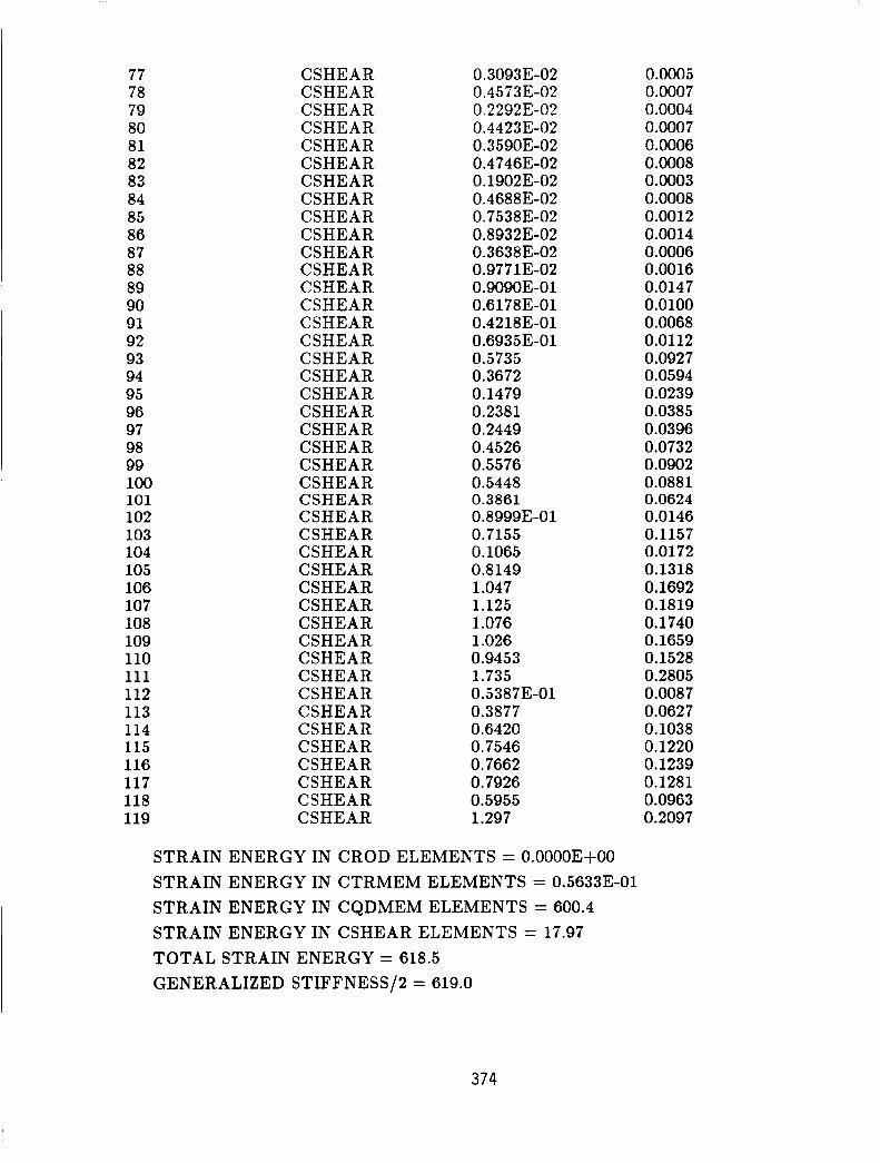
The second example is known as the intermediate complexity wing and is just a sim- plified NASTRAN model of the load carrying portion of a wing. Shown in figure 2 broken into its component elements and their numbering scheme, is a depiction of the wing. The model consists of quadrilateral membrane elements for most of the top and bottom skins, two triangular membrane elements for the outboard corner elements on the top and bottom skins, rod elements for all the posts, and shear elements for all the ribs and spars. The inboard top and bottom skin points rigidly fixed. The strain energy program output for the first mode of the model is given in table 11. As you can see, the program accurately produces zero strain energy in all the rod elements for the first bending mode of the wing. The difference in the values for the total struc- tural strain energy and one-half the generalized stiffness can be attributed to the dif- ferent formulations of the stiffness matrices of the plate membrane and shear elements.
The final example is a part of the Large Space Structures Technology Program at the Flight Dynamics Laboratory. A NASTRAN model of the twelve meter truss structure is shown in figure 3. The elements aren't numbered because of the large number of elements in the model. The model consists of bar elements for the horizontal and vertical elements and rod elements for all the diagonals. The diagonal members contain the viscoelastic dampers on the actual structure. The model is supported at the base with a series of elastic elements. The strain energy output for the second mode is given in table 111. This is the first torsion mode of the truss, so most of the strain energy is in the diagonal members. This is verified by the modal strain energy program. The loss factor for the entire structure has been predicted and is awaiting test results for verification.
CONCLUDING REMARKS
A FORTRAN program that calculates element strain energies has been developed and
369

verified. This program gives COSMIC NASTRAN a capability that was only previously available for static analysis. Work is currently underway to develop DMAP instructions to calculate modal strain energies directly in KASTRA?;. With the ever increasing trend toward lighter structures, damping materials will see increased use in all types of structures. A simple, accurate method, such as the modal strain energy method, to predict structural damping is essential.
REFERENCES
1. Venkayya, V.B. and Tischler, V.A., ““ANALYZE” - Analysis of Aerospace Structures with Membrane Elements”, AFFDL-TR-78-170, Aug. 1978.
2. The NASTRAN User’s Manual, Jun. 1985.
3. Johnson, C.D., Kienholz, D.A., and Rogers, L.C., “Finite Element Prediction of Damp- ing in Beams with Constrained Viscoelastic Layers,” Shock and Vibration Bulletin, No. 50, Part 1, May 1981, pp. 71-82.
4. Johnson, C.D. and Kienholz, D.A., “Design and Testing of a Sixty Foot Damped Generic Space Truss.”
TABLE I - RECTANGULAR WING BOX STRAIN ENERGIES
MODE 2
Element ID
5000 1 50002 50003 500 502 503 504 505 506 507 508 509 50004 50005 50006 50007 50008 50009 10001 10002
Element Type
CBAR CBAR CBAR CELAS CELAS CELAS CELAS CELAS CELAS CELAS CELAS CELAS CROD CROD CROD CROD CROD CROD CTRMEM CTRMEM
Element Strain Energy
-0.40683-06 6.446
0.2516 -0.60 10E-06
0.27493-01 0.28 10E-01 69.68 55.31 50.50 0.5442
0.1016
O.OOOOE+OO 0.0000E+OO 1.088 0.1927 0.2032 117.4 116.7
0.96353-0 1
0.0000E+OO
% Strain Energy
0.0000 0.2810 0 .oooo 0.0110 0.0012 0.0012 3.0378 2.4114 2.2015 0.0237 0.0042 0.0044 0.0000 0.0000 0.0000 0.0475 0.0084 0.0089 5.1190 5.0897
370

10011 10012 20001 20002 2001 1 20012 10003 10004 20003 20004 30001 30002 30003 30004 30005 30006 40001 40002 40003 40004 40005 40006
CTRMEM CTRMEM CTRMEM CTRMEM CTRMEM CTRMEM CQDMEM CQDMEM CQDMEM CQDMEM CSHEAR CSHEAR CSHEAR CSHEAR CSHEAR CSHEAR CSHEAR CSHEAR CSHEAR CSHEAR CSHEAR CSHEAR
137.4 117.8 115.1 119.7 132.1 115.9 218.9 166.3 200.6 189.0 29.60 88.67 34.38 80.61 72.90 28.34 12.29 8.467
3.315 3.752
0.62633-02
0.98053-05
5.9880 5.1372 5.0171 5.2185 5.7594 5.0520 9.5449 7.2488 8.7462 8.2413 1.2904 3.8657 1.4987 3.5140 3.1781 1.2355 0.5360 0.3691 0.0003 0.1445 0.1636 0.0000
STRAIN ENERGY IN CELAS ELEMENTS = 176.5 STRAIN ENERGY IN CBAR ELEMENTS = 6.446 STRAIN ENERGY IN CROD ELEMENTS = 1.484 STRAIN ENERGY IN CTRMEM ELEMENTS = 972.1 STRAIN ENERGY IN CQDMEM ELEMENTS = 774.9 STRAIN ENERGY IN CSHEAR ELEMENTS = 362.3 TOTAL STRAIN ENERGY = 2294. GENERALIZED STIFFNESS/2 = 2294.
TABLE I1 - INTERMEDIATE COMPLEXITY WING STRAIN ENERGIES
MODE 1
Element ID
120 121 122 123 124 125 126 127 128
Element Type
CROD CROD CROD CROD CROD CROD CROD CROD CROD
Element Strain Energy
0.0000E+00 0. OOOOE +oo 0.0000E +oo 0.0000E +oo O.OOOOE+OO
0.0000E +oo 0.0000E +00 0.0000E +oo
0.0000E + 00
% Strain Energy
0.0000 0.0000 0.0000 0.0000 0.0000 0.0000 0.0000 0.0000 0.0000
371

129 130 131 132 133 134 135 136 137 138 139 140 14 1 142 143 144 145 146 147 148 149 150 151 152 153 154 155 156 157 158 1 2 3 4 5 6 7 8 9 10 11 12 13 14 15 16 17 18 19 20 21 22 23
CROD CROD CROD CROD CROD CROD CROD CROD CROD CROD CROD CROD CROD CROD CROD CROD CROD CROD CROD CROD CROD CROD CROD ,
CROD CROD CROD CROD CROD CROD CROD CTRMEM CTRMEM CQDMEM CQDMEM CQDMEM CQDMEM CQDMEM CQDMEM CQDMEM CQDMEM CQDMEM CQDMEM CQDMEM CQDMEM CQDMEM CQDMEM CQDMEM CQDMEM CQDMEM CQDMEM CQDMEM CQDMEM CQDMEM
0.0000E $00 0.OOOOE $00 0.OOOOE $00 0.0000E+OO 0.0000E +oo 0.0000E +oo 0.0000E +00 0.0000E+OO 0.0000E +00
0.0000E + 00 0.0000E +00
0.0000E+OO
0.0000E+00
0.0000E $00 0.0000E +Oo 0.0000E +Oo 0.0000E+OO
0.0000E +oo
0.0000E+OO 0.0000E +Oo 0.0000E +00 0.0000E + 00 0.0000E+OO
0.0000E + 00
0.0000E +00
0.0000E $00
0.0000E + 00
O.OOOOE+OO
0.0000E+OO O.OOOOE+OO
0.28173-01 0.28173-01 0.81323-01 0.8 132E-01 0.68093-01 0.68093-01 0.1561 0.1561 0.6461 0.6461 0.7805 0.7805 0.7629 0.7629 0.9026 0.9026 2.573 2.573 3.169 3.169 3.299 3.299 3.306
0.0000 0.0000 0.0000 0.0000 0.0000 0.0000 0.0000 0 .oooo 0.0000 0.0000 0 .oooo 0.0000 0.0000 0.0000 0 .oooo 0.0000 0.0000 0.0000 0.0000 0.0000 0.0000 0.0000 0.0000 0.0000 0 .oooo 0.0000 0.0000 0.0000 0.0000 0 .oooo 0.0046 0.0046 0.0131 0.0131 0.0110 0.01 10 0.0252 0.0252 0.1045 0.1045 0.1262 0.1262 0.1234 0.1234 0.1459 0.1459 0.4161 0.4161 0.5124 0.5124 0.5335 0.5335 0.5345
372

24 25 26 27 28 29 30 31 32 33 34 35 36 37 38 39 40 41 42 43 44 45 46 47 48 49 50 51 52 53 54 55 56 57 58 59 60 61 62 63 64 65 66 67 68 69 70 71 72 73 74 75 76
CQDMEM CQDMEM CQDMEM CQDMEM CQDMEM CQDMEM CQDMEM CQDMEM CQDMEM CQDMEM CQDMEM CQDMEM CQDMEM CQDMEM CQDMEM CQDMEM CQDMEM CQDMEM CQDMEM CQDMEM CQDMEM CQDMEM CQDMEM CQDMEM CQDMEM CQDMEM CQDMEM CQDMEM CQDMEM CQDMEM CQDMEM CQDMEM CQDMEM CQDMEM CQDMEM CQDMEM CQDMEM CQDMEM CQDMEM CQDMEM CQDMEM CSHEAR CSHEAR CSHEAR CSHEAR CSHEAR CSHEAR CSHEAR CSHEAR CSHEAR CSHEAR CSHEAR CSHEAR
3.306 5.762 5.762 7.520 7.520 7.967 7.967 7.312 7.312 9.504 9.504 12.89 12.89 14.20 14.20 12.59 12.59 12.67 12.67 17.60 17.60 21.24 21.24 19.38 19.38 13.58 13.58 17.25 17.25 20.66 20.66 16.06 16.06 6.645 6.645 17.18 17.18 21.31 21.31 23.16 23.16 0.43183-01 0.58333-04 0.44193-01 0.668 1 E-03 0.15593-02 0.33 17E-01 0.36893-02 0.15793-01 0.32363-02 0.6835E-02 0.32953-02 0.71 11E-02
0.5345 0.9316 0.9316 1.2159 1.2159 1.2882 1.2882 1.1824 1.1824 1.5367 1.5367 2.0840 2.0840 2.2956 2.2956 2.0364 2.0364 2.0479 2.0479 2.8462 2.8462 3.4346 3.4346 3.1329 3.1329 2.1953 2.1953 2.7891 2.7891 3.3399 3.3399 2.5971 2.5971 1.0744 1.0744 2.7780 2.7780 3.4457 3.4457 3.7449 3.7449 0.0070 0.0000 0.0071 0.0001 0.0003 0.0054 0.0006 0.0026 0.0005 0.0011 0.0005 0.0011
373
77 78 79 80 81 82 83 84 85 86 87 88 89 90 91 92 93 94 95 96 97 98 99 100 101 102 103 104 105 106 107 108 109 110 111 112 113 114 115 116 117 118 119
CSHEAR CSHEAR CSHEAR CSHEAR CSHEAR CSHEAR CSHEAR CSHEAR CSHEAR CSHEAR CSHEAR CSHEAR CSHEAR CSHEAR CSHEAR CSHEAR CSHEAR CSHEAR CSHEAR CSHEAR CSHEAR CSHEAR CSHEAR CSHEAR CSHEAR CSHEAR CSHEAR CSHEAR CSHEAR CSHEAR CSHEAR CSHEAR CSHEAR CSHEAR CSHEAR CSHEAR CSHEAR CSHEAR CSHEAR CSHEAR CSHEAR CSHEAR CSHEAR
0.3093E-02 0.45733-02 0.22923-02 0.44233-02 0.35903-02 0.47463-02 0.19023-02 0.46883-02 0.75383-02 0.89323-02 0.36383-02 0.97713-02 0.9090E-0 1 0.61783-01 0.42183-01 0.69353-01 0.5735 0.3672 0.1479 0.2381 0.2449 0.4526 0.5576 0.5448 0.3861
0.7155 0.1065 0.8149 1.047 1.125 1.076 1.026 0.9453 1.735
0.3877 0.6420 0.7546 0.7662 0.7926 0.5955 1.297
0.89993-0 1
0.538 7E-01
STRAIN ENERGY IN CROD ELEMENTS = 0.0000E+OO STRAIN ENERGY IN CTRMEM ELEMENTS 0.56333-01 STRAIN ENERGY IN CQDMEM ELEMENTS = 600.4 STRAIN ENERGY IN CSHEAR ELEMENTS = 17.97 TOTAL STRAIN ENERGY = 618.5 GENERALIZED STIFFNESS/2 = 619.0
0.0005 0.0007 0.0004 0.0007 0.0006 0.0008 0.0003 0.0008 0.0012 0.0014 0.0006 0.0016 0.0147 0.0100 0.0068 0.0112 0.0927 0.0594 0.0239 0.0385 0.0396 0.0732 0.0902 0.0881 0.0624 0.0146 0.1157 0.0172 0.1318 0.1692 0.1819 0.1740 0.1659 0.1528 0.2805 0.0087 0.0627 0.1038 0.1220 0.1239 0.1281 0.0963 0.2097
374

TABLE 111 - TWELVE METER TRUSS STRAIN ENERGIES , #et?
MODE 2
Element ID
101 102 103 104 106 107 108 109 111 112 113 114 116 117 118 119 120 121 122 123 125 126 127 128 130 131 132 133 135 136 137 138 139 140 141 142 144 145 146 147 149 150 151 152 154
Element Type
CBAR CBAR CBAR CBAR CBAR CBAR CBAR CBAR CBAR CBAR CBAR CBAR CBAR CBAR CBAR CBAR CBAR CBAR CBAR CBAR CBAR CBAR CBAR CBAR CBAR CBAR CBAR CBAR CBAR CBAR CBAR CBAR CBAR CBAR CBAR CBAR CBAR CBAR CBAR CBAR CBAR CBAR CBAR CBAR CBAR
Element Strain Energy
1.740 1.724 1.127 1.155 0.6792 0.661 1 0.3441 0.3522 0.1476 0.1436 0.44343-01 0.45313-01 0.7 1873-02 0.69483-02 0.22783-03 0.20493-03 0.17673-01 0.50473-02 0.43263-02 0.56523-02 0.22553-02 0.30963-02 0.11823-02 0.18333-02 0.36333-03 0.65763-03 0.10583-03 0.25973-03 0.22773-04 0.30043-04 0.40123-04 0.10463-04 1.740 1.724 1.127 1.155 0.6792 0.6611 0.3441 0.3522 0.1476 0.1436 0.44343-01 0.453 1 3-01 0.71873-02
% Strain Energy
6.0085 5.953 7 3.8917 3.9862 2.3449 2.2827 1.1880 1.2160 0.5098 0.4956 0.1531 0.1564 0.0248 0.0240 0.0008 0.0007 0.0610 0.0174 0.0149 0.0195 0.0078 0.0107 0.0041 0.0063 0.0013 0.0023 0.0004 0.0009 0.0001 0.0001 0.0001 0.0000 6.0085 5.9537 3.8917 3.9862 2.3449 2.2827 1.1880 1.2160 0.5098 0.4956 0.1531 0.1564 0.0248
375

155 156 157 158 159 160 161 163 164 165 166 168 169 170 171 173 174 175 176 201 202 203 204 205 206 207 208 209 210 211 212 213 214 215 216 217 218 219 220 22 1 222 223 224 225 226 227 228 229 230 23 1 232 233 234
CBAR CBAR CBAR CBAR CBAR CBAR CBAR CBAR CBAR CBAR CBAR CBAR CBAR CBAR CBAR CBAR CBAR CBAR CBAR CBAR CBAR CBAR CBAR CBAR CBAR CBAR CBAR CBAR CBAR CBAR CBAR CBAR CBAR CBAR CBAR CBAR CBAR CBAR CBAR CBAR CBAR CBAR CBAR CBAR CBAR CBAR CBAR CBAR CBAR CBAR CBAR CBAR CBAR
0.69483-02 0.2278E-03 0.20493-03 0.17673-01 0.504 73-02 0.43263-02 0.56523-02 0.22553-02 0.30963-02 0.1 1823-02 0.18333-02 0.36333-03 0.65763-03 0.10583-03 0.25973-03 0.22773-04 0.30043-04 0.40123-04 0.10463-04 0.10543-03 0.92583-03 0.61643-03 0.67523-03 0.57263-03 0.57263-03 0.55833-03 0.5 1893-03 0.47043-03 0.39503-03 0.39503-03 0.32613-03 0.27533-03 0.21573-03 0.14823-03 0.14823-03 0.85623-04 0.4871E-04 0.16003-04 0.87163-05 0.10553-03 0.92573-03 0.61633-03 0.67553-03 0.57253-03 0.57253-03 0.55833-03 0.51 91E-03 0.47063-03 0.39503-03 0.39503-03 0.32603-03 0.27543-03 0.21583-03
0.0240 0.0008 0.0007 0.0610 0.0174 0.0149 0.0195 0.0078 0.0107 0.004 1 0.0063 0.0013 0.0023 0.0004 0.0009 0.0001 0.0001 0.0001 0.0000 0.0004 0.0032 0.002 1 0.0023 0.0020 0.0020 0.0019 0.0018 0.0016 0.0014 0.0014 0.0011 0.0010 0.0007 0.0005 0.0005 0.0003 0.0002 0.0001 0 .oooo 0.0004 0.0032 0.0021 0.0023 0.0020 0.0020 0.0019 0.0018 0.0016 0.0014 0.0014 0.0011 0.0010 0.0007
376

235 236 237 238 239 240 24 1 242 243 244 245 246 24 7 248 249 250 251 252 253 254 255 256 257 258 259 260 261 262 263 264 265 266 267 268 269 2 70 271 272 273 2 74 275 276 277 278 279 280 30 1 302 303 304 305 306 307
CBAR CBAR CBAR CBAR CBAR CBAR CBAR CBAR CBAR CBAR CBAR CBAR CBAR CBAR CBAR CBAR CBAR CBAR CBAR CBAR CBAR CBAR CBAR CBAR CBAR CBAR CBAR CBAR CBAR CBAR CBAR CBAR CBAR CBAR CBAR CBAR CBAR CBAR CBAR CBAR CBAR CBAR CBAR CBAR CBAR CBAR CBAR CBAR CBAR CBAR CBAR CBAR CBAR
0.14823-03 0.14823-03 0.8558E-04 0.48 71E-04 0.15963-04 0.86533-05 0.10543-03 0.92583-03 0.61643-03 0.67523-03 0.57263-03 0.57263-03 0.55833-03 0.51 893-03 0.47043-03 0.39503-03 0.39503-03 0.326 1 3-03 0.27533-03 0.21573-03 0.14823-03 0.14823-03 0.85623-04 0.48713-04 0.16003-04 0.87163-05 0.10553-03 0.92573-03 0.61633-03 0.67553-03 0.57253-03 0.57253-03 0.55833-03 0.51913-03 0.4 7063-03 0.39503-03 0.39503-03 0.32603-03 0.27543-03 0.2 1583-03 0.14823-03 0.14823-03 0.85583-04 0.48 7 1 3-04 0.15963-04 0.86523-05 0.75723-01 0.57783-01 0.94 223-0 1 0.57653-01 0.86043-0 1 0.5 1673-0 1 0.69323-01
377
0.0005 0.0005 0.0003 0.0002 0.0001 0.0000 0.0004 0.0032 0.0021 0.0023 0.0020 0.0020 0.0019 0.0018 0.0016 0.0014 0.0014 0.0011 0.0010 0.0007 0.0005 0.0005 0.0003 0.0002 0.0001 0.0000 0.0004 0.0032 0.0021 0.0023 0.0020 0.0020 0.0019 0.0018 0.0016 0.0014 0.0014 0.0011 0.0010 0.0007 0.0005 0.0005 0.0003 0.0002 0.0001 0.0000 0.2614 0.1995 0.3253 0.1990 0.2971 0.1784 0.2393

308 309 310 31 1 312 313 314 315 316 317 318 319 320 32 1 322 323 324 325 326 327 328 329 330 33 1 332 333 334 335 336 337 338 339 340 34 1 342 343 344 345 346 347 348 349 350 351 352 353 354 355 356 357 358 359 360
CBAR CBAR CBAR CBAR CBAR CBAR CBAR CBAR CBAR CBAR CBAR CBAR CBAR CBAR CBAR CBAR CBAR CBAR CBAR CBAR CBAR CBAR CBAR CBAR CBAR CBAR CBAR CBAR CBAR CBAR CBAR CBAR CBAR CBAR CBAR CBAR CBAR CBAR CBAR CBAR CBAR CBAR CBAR CBAR CBAR CBAR CBAR CBAR CBAR CBAR CBAR CBAR CBAR
0.46993-0 1 0.52173-01 0.3316E-01 0.33173-01 0.22023-01 0.15383-01 0.77853-02 0.378 1E-02 0.88503-03 0.757 1 3-01 0.57773-0 1 0.94213-01 0.57643-01 0.86043-0 1 0.5 1673-0 1 0.69313-01 0.46993-01 0.52183-01 0.33 163-01 0.33 183-01 0.22023-01 0.15393-01 0.77873-02 0.3 7833-02 0.885 1E-03 0.75723-01 0.5 7 783-01 0.94223-0 1 0.57653-01 0.86043-01 0.51673-01 0.69323-01 0.46993-01 0.52173-01 0.33163-01 0.33173-01 0.22023-01 0.15383-01 0.77863-02 0.378 1 3-02 0.88503-03 0.757 1 E-01 0.5 7773-0 1 0.94213-01 0.57643-0 1 0.8604E-0 1 0.51673-01 0.693 1 3-01 0.46993-01 0.521 8E-01 0.33163-01 0.33 183-01 0.22033-01
0.1622 0.1801 0.1145 0.1145 0.0760 0.0531 0.0269 0.0131 0.0031 0.2614 0.1995 0.3253 0.1990 0.2971 0.1784 0.2393 0.1622 0.1801 0.1145 0.1145 0.0760 0.0531 0.0269 0.0131 0.003 1 0.2614 0.1995 0.3253 0.1990 0.2971 0.1784 0.2393 0.1622 0.1801 0.1145 0.1145 0.0760 0.0531 0.0269 0.0131 0.003 1 0.2614 0.1995 0.3253 0.1990 0.2971 0.1784 0.2393 0.1622 0.1801 0.1145 0.1145 0.0760
378

361 362 363 364 500 501 502 503 504 505 506 507 508 509 510 511 512 513 514 515 516 517 518 519 520 52 1 522 523
CBAR CBAR CBAR CBAR CELAS CELAS CELAS CELAS
CELAS CELAS CELAS CELAS CELAS CELAS CELAS CELAS CELAS CELAS CELAS CELAS CELAS CELAS CELAS CELAS CELAS CELAS CELAS
C-ELAS
0.15393-01 0.77873-02 0.3783E-02 0.88523-03 0.33673-03 0.28 13E-05 0.33673-03 0.28133-05 0.33673-03 0.28123-05 0.33673-03 0.28123-05 0.14653-16 0.49493-10 0.14653-16 0.49493-10 4.794 0.78083- 10 4.794 0.78083-10 0.9110E-02 0.89643-02 0.91 10E-02 0 39643-02 0.91 11E-02 0.89643-02 0.91 11E-02 0.89643-02
STRAIN ENERGY IN CELAS ELEMENTS = 9.662 STRAIN ENERGY IN CBAR ELEMENTS = 19.30 TOTAL STRAIN ENERGY = 28.96 GENERALIZED STIFFNESS/% = 28.96
0.0531 0.0269 0.0131 0.0031 0.0012 0.0000 0.0012 0.0000 0.0012 0.0000 0.0012 0.0000 0.0000 0.0000 0.0000 0.0000 16.5529 0.0000 16.5529 0.0000 0.0315 0.0309 0.0315 0.0309 0.0315 0.0310 0.0315 0.0310
379
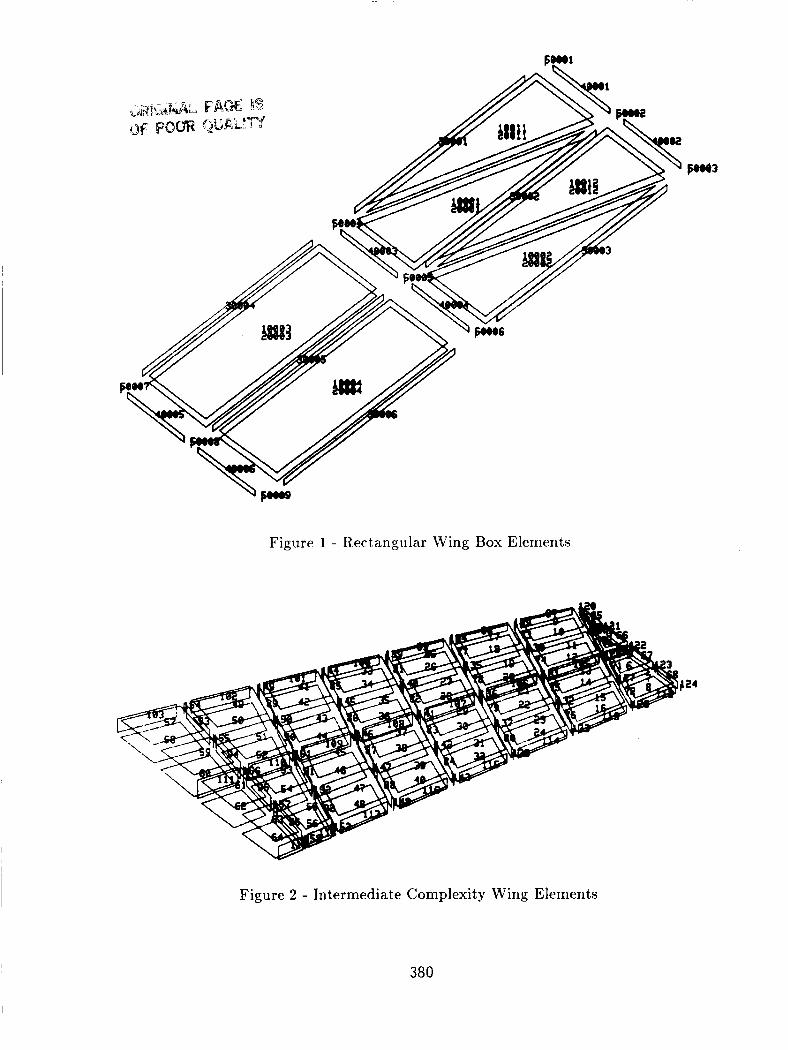
Figure 2 - Intermediate Complexity Wing Elements
380
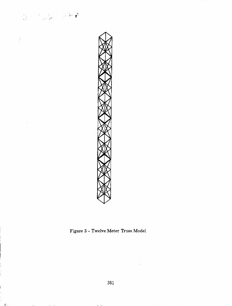
Figure 3 - Twelve Meter Truss Model
381