modas displays fia-f3 brit 2008 - bosch · pdf file5 modas-displays fia-f3 2 motronic –...
TRANSCRIPT
Bosch MotorsportModas Displays F3 2008


3
MODAS-DISPLAYS FIA-F3
Contents Contents ...............................................................................................................3
1 Working with MODAS-DISPLAYS FIA F3................................................................4
2 Motronic – Functions ...............................................................................................5
2.1 ENGINE – Display .............................................................................................5
2.2 ENGINE – Throttle.............................................................................................6
2.3 ENGINE – Fuel-Pump .......................................................................................7
2.4 ENGINE – Ignition .............................................................................................7
2.5 Lifetime/Cons – Min/Max and display thresholds...............................................8
2.6 Lifetime/Cons – Lifetime engine ........................................................................8
3 ESC – Escape button ............................................................................................10
4 CHASSIS – Functions ...........................................................................................11
4.1 CHASSIS – Suspension ..................................................................................12
4.1.1 CHASSIS – Suspension Front Left ............................................................12
4.1.2 CHASSIS – Suspension Front Right..........................................................13
4.1.3 CHASSIS – Suspension Rear Left.............................................................13
4.1.4 CHASSIS – Suspension Rear Right ..........................................................13
4.2 CHASSIS – Steering........................................................................................14
4.3 CHASSIS – Acceleration Long ........................................................................14
4.4 CHASSIS – Acceleration Trans .......................................................................15
4.5 CHASSIS – Analogue......................................................................................15
5 RACE – Function...................................................................................................16
5.1 RACE – Dash ..................................................................................................16
5.2 RACE – Memo.................................................................................................17
5.3 RACE – Memo, Datavers ................................................................................18
5.4 RACE – Wheel ................................................................................................18
5.5 RACE – Wheel, Lap parameters .....................................................................19
5.6 RACE – Gear, Gearshift settings.....................................................................21
5.7 RACE – Gear...................................................................................................23
6 ASCII – Decimal – Table .......................................................................................25
7 CDT – error list ......................................................................................................26

4
MODAS-DISPLAYS FIA-F3
1 Working with MODAS-DISPLAYS FIA F3
When MODAS has been started, the FIA-F3 display will be automatically loaded. The
term display means measure and program boxes. These boxes provide easy monitor-
ing and programming of all the important functions of the ECU (Engine Control Unit)
and the Card-Memory, for the use in F3 race cars using the FIA F3 2008-2010
technology.
All important Motronic functions can be found in the option “Engine” and “Life-
time/Cons”. These functions include data-measuring-boxes for the various parameters,
for example pressure, temperature and revolutions. There is also the possibility to read
any errors, check Min/ Max measurements, these may also be reset (see also chapter
2).
The vehicle channels can be calibrated in the “Suspension“, “Acceleration Steering”
and the “analogue” display. In this function the sensor characteristic curves are saved
in the CardMemory, for example the suspension sensors (see also chapter 3).
The option “Race“ contains measuring and programming boxes which offer the
possibility to set the driver functions like for example pit speed limiter, and the possibil-
ity to program shift LEDs (see also chapter 4).
Note: Some functions may not be supported in certain program versions.

5
MODAS-DISPLAYS FIA-F3
2 Motronic – Functions
When the option Engine has been selected a list of Motronic functions will appear in
the following window.
2.1 ENGINE – Display
The most important engine parameters will be shown in this display. This function
contains for example engine revolutions, throttle valve angle, temperatures, pressures,
ignition angle, injection time.

6
MODAS-DISPLAYS FIA-F3
2.2 ENGINE – Throttle
This function allows
adjustment of the throttle
potentiometer.
The throttle sensor can be
calibrated (learning), when a
new engine is installed in the
car. The reference point for
the calibration is the me-
chanical throttle-valve-stop.
Calibration of the throttle valve: Release the throttle pedal and idle stop and click the
macro “set throttle“.
The calibration can only be carried out when the
engine is stopped (B_nmot = FALSE) and there is no
throttle-valve failure (E_dk = FALSE).

7
MODAS-DISPLAYS FIA-F3
2.3 ENGINE – Fuel-Pump
This option contains the fuel pump function. The pump will be switched on for ten
seconds when the
“pump“ macro is se-
lected. The engine must
be stopped (B_nmot =
FALSE) and communica-
tion between the PC and
the ECU must be active.
(B_klineok = TRUE).
2.4 ENGINE – Ignition
This display shows the ignition angle offset from the application tool. Positive numbers
indicate more advance and
negative numbers a less
ignition advance.

8
MODAS-DISPLAYS FIA-F3
2.5 Lifetime/Cons – Min/Max and display thresholds
This display shows all
the Min/ Max data. It
includes: engine
revolution (max), fuel
pressure (min/ max), oil
pressure (min), engine
temperature (max), oil
temperature (min/max),
battery-voltage (min).
The alarm thresholds
can be set in the box
“Display Thresholds”:
TMOTMX for maximum engine temperature, UBMN for minimum battery voltage,
POELMN for minimum oil pressure and PFUELMN for minimum fuel pressure.
2.6 Lifetime/Cons – Lifetime engine
In its lifetime, the MS3.1
saves specific lifetime
MIN/MAX data. This
includes the operational
time of the ECU (ltecu) in
its life, the driven dis-
tance in km (ltdistkm_w),
the driven distance in m
(ltdistm_w), the engine
operating time (ltmot_w),
the engine distance
(ltdisteng), the time spent
above a preset RPM limit ltnmotmo_w), max engine revolution limit data (ltnmotmx_w)
and the fuel consumption.
9
MODAS-DISPLAYS FIA-F3
The distance counter can be reset with the macro “Clr Dist“.
The fuel consumption can be reset with the macro “Clr Cons“.
Only the engine manufacturer can reset all the other macros.

10
MODAS-DISPLAYS FIA-F3
3 ESC – Escape button
- At any time, a move backwards through the programme can be done with the
“ESC“ button.

11
MODAS-DISPLAYS FIA-F3
4 CHASSIS – Functions
MODAS is used to calibrate the vehicle chassis channels. There is an adjustment
facility using the button “Chassis“. The characteristic curves made with the macro are
saved in the CardMemory and have to be adjusted when there is a change of sensors
or the CardMemory.
The option “Chassis“ consists of several chassis functions:
- Suspension,
- Steering,
- Acceleration Long,
- Acceleration Trans,
- All Chassis Channels.

12
MODAS-DISPLAYS FIA-F3
4.1 CHASSIS – Suspension
The first of the suspension functions allows calibrating single suspension sensor. All
the suspension sensors can be reset (“ZERO ALL“) together.
4.1.1 CHASSIS – Suspension Front Left
To carry out adjustment:
- The sensor which is to be
calibrated is moved to any
position (for example the
mechanical stop: Posi-
tion1). For this position the
input in “SUS_IN_FL“ is
the physical data 0.
- Position 1 can be saved in
the CardMemory with the
“Car down“ button. The
measured voltage can be checked with the “ususinfl“ label.
- The sensor is then moved to a second position (for example the opposite mechani-
cal stop: Position 2). The difference between position 1 and 2 is the input for the
label “SUS_OUT_FL“ (here: 10 mm).

13
MODAS-DISPLAYS FIA-F3
- Position 2 can be saved with the “car up“ button. The measured voltage can be
checked with the label “ususoufl”.
- At this point the characteristic curve of the sensor is defined. The physical data can
be checked with the label “susflchk“.
- The button “ZERO“ resets the sensor, with the sensor in the desired zero reference
position.
4.1.2 CHASSIS – Suspension Front Right
The adjustment of this function is the same as the “Suspension Front Left“.
4.1.3 CHASSIS – Suspension Rear Left
The adjustment of this function is the same as the “Suspension Front Left “.
4.1.4 CHASSIS – Suspension Rear Right
The adjustment of this function is the same as the “Suspension Front Left “.
14
MODAS-DISPLAYS FIA-F3
4.2 CHASSIS – Steering
The steering angle can be adjusted with the “Steering“ button.
The adjustment of this function is similar the adjustment of the “Suspension Front Left
“ function. Instead of the suspension position the input is the steer angle sensor
(“STEERPOS1“ und “STEERPOS2).
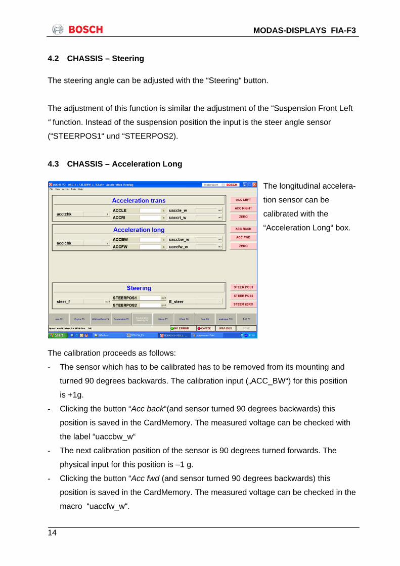
4.3 CHASSIS – Acceleration Long
The longitudinal accelera-
tion sensor can be
calibrated with the
“Acceleration Long“ box.
The calibration proceeds as follows:
- The sensor which has to be calibrated has to be removed from its mounting and
turned 90 degrees backwards. The calibration input („ACC_BW“) for this position
is +1g.
- Clicking the button “Acc back“(and sensor turned 90 degrees backwards) this
position is saved in the CardMemory. The measured voltage can be checked with
the label “uaccbw_w“
- The next calibration position of the sensor is 90 degrees turned forwards. The
physical input for this position is –1 g.
- Clicking the button “Acc fwd (and sensor turned 90 degrees backwards) this
position is saved in the CardMemory. The measured voltage can be checked in the
macro “uaccfw_w“.

15
MODAS-DISPLAYS FIA-F3
- The characteristic curve has now been defined for the sensor. The physical data
can be checked with the label “acclchk“.
- For “ZERO“-point adjustment of the sensor, its position has to be horizontal
(mounted in the car).
4.4 CHASSIS – Acceleration Trans
The transversal acceleration
sensor can be calibrated
with the “Acceleration
Trans“ box.
This sensor has the same
calibration as the longitudi-
nal Acceleration sensor (see
chapter 3.3).
The input +1g is when the
sensor has been turned 90
degrees to the left (car cornering right) and can be edited by the label “ACCLE“.
The input -1g is when the sensor has been turned 90 degrees to the right (car corner-
ing left) and can be edit by the label “ACCRI“
4.5 CHASSIS – Analogue
Selecting the option All Chassis Channel provides a display of all the voltages of the
CardMemory.

16
MODAS-DISPLAYS FIA-F3
5 RACE – Function
The function “RACE“ provides quick access to all of the lap information. This function
contains for example the gear setup, the programming of gear ratios, lap- and seg-
ment distances.
5.1 RACE – Dash
This function controls the map switch and the LEDs (oil- and diagnostic LEDs).
The display left, shows the
map position conditions one
and two, the active diagnos-
tic LED (B_mil = true), and
the oil warning LED
(B_oellamp = true). mappos
is showing the current map
position.
Further more you see the brake balance in procent (pbrproz_f /_r) and the absolute
Pressure front (pbrk_f) and rear (pbrk_r).
The revs for the shift LEDs can also be set there. This is dependent on the gear
engaged, that is why the 5 LEDs have to be set up for each gear in the maps
KLNSHGEAR1…6.
The pit speed limiter can also be set up: the target speed should be set in VMAXO.
The codeword CWVMAX allows turning off the speed limiter by setting it to 0. In order
to turn on the limiter this codeword has to be set to 1.

17
MODAS-DISPLAYS FIA-F3
5.2 RACE – Memo
The clock in the CardMemory contains the real time and has a battery backup. This
real time is saved with each data file and shown in WinDarab. The clock in the system
has to be reset when the battery has been changed.
It is possible to read in
the active memory time
by clicking “Read Clock.“
The time is shown in the
labels “tclomemyr,
tclomemmon ...“. The
new time can be defined
in the labels “CLOME-
MYR, CLOMEMMON ...“.
This can be set in the
CardMemory by clicking
“Set Clock“.
Different operational conditions of the memory can be checked with the bits
B_memcan, -card, -cardn, and -rec.
B_memcan means that a CM 40 is connected to the chassis loom
B_memcard means that a initalized card is in the slot
B_memcardn means that a new initalized (without data) card is in the slot
B:memrec means that the CM 40 is recording data, and so definitly must be some
Data on the card !
This page also displays the status of the Accident Data Recorder (ADR). For further
information, please contact the ADR manufacturer.
Note: when putting the beacon transmitter in front of the receiver, the bits B_lappin
and B_lapin should get true. If not, there is a problem.
The parameters FLLAPMIN and FLLAPMAX allow avoiding wrong beacon impulses.

18
MODAS-DISPLAYS FIA-F3
After getting a laptrigger, the ECU will wait till a distance equal to LLAP * FLLAPMIN
has been driven before recognising a beacon impulse as a laptrigger.
In the same way, if no laptrigger has been detected after a distance equal to LLAP *
FLLAPMAX has been driven, the ECU will set a laptrigger. (it is possible to switch this
function off by setting this parameter to 4).
Typical values for these parameters are thus: FLLAPMIN = 0.6 and FLLAPMAX = 2.
5.3 RACE – Memo, Datavers
The name of the data version is shown in the label DATAVERS, a note may also be
added. WinDARAB will show this name.
The data is shown “default-mode“ as decimal numbers. By “right-clicking“ with the
mouse pointer at the displayed data, and selecting the “ASCII-character“ option, the
data can be changed to an ASCII-expression.
Each character can be edited with the decimal number mode. An ASCII-table is shown
in chapter 6.
5.4 RACE – Wheel
For the correct calculation of the car speed, the following data is needed:
1) Impulses for each
wheel revolution
“AIMRU“
2) Wheel diameter
“UMRAD“
The speed (signal) can
be read in the macro
boxes vfzg_w and
vfzgmph_w.
Each values must be
filled in for the front (_F)
19
MODAS-DISPLAYS FIA-F3
and rear (_R) axel.
The codeword CW4WSB indicates weather you use a 4 wheel speed box (=1)
Or not ( =0)
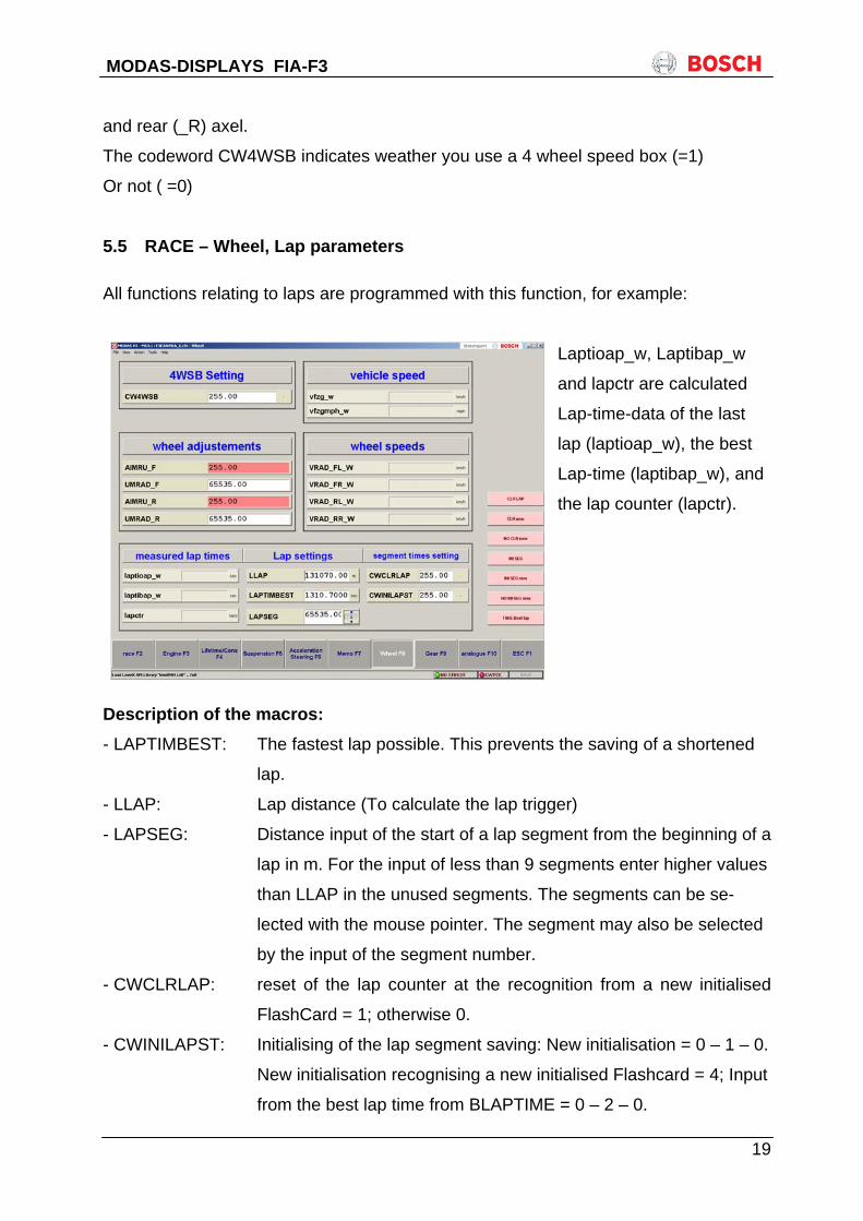
5.5 RACE – Wheel, Lap parameters
All functions relating to laps are programmed with this function, for example:
Laptioap_w, Laptibap_w
and lapctr are calculated
Lap-time-data of the last
lap (laptioap_w), the best
Lap-time (laptibap_w), and
the lap counter (lapctr).
Description of the macros: - LAPTIMBEST: The fastest lap possible. This prevents the saving of a shortened
lap.
- LLAP: Lap distance (To calculate the lap trigger)
- LAPSEG: Distance input of the start of a lap segment from the beginning of a
lap in m. For the input of less than 9 segments enter higher values
than LLAP in the unused segments. The segments can be se-
lected with the mouse pointer. The segment may also be selected
by the input of the segment number.
- CWCLRLAP: reset of the lap counter at the recognition from a new initialised
FlashCard = 1; otherwise 0.
- CWINILAPST: Initialising of the lap segment saving: New initialisation = 0 – 1 – 0.
New initialisation recognising a new initialised Flashcard = 4; Input
from the best lap time from BLAPTIME = 0 – 2 – 0.
20
MODAS-DISPLAYS FIA-F3
The following macros can be used in the program: - CLRLAP: The active lap counter can be reset
- CLR new: The lap counter will automatically be erased (CWCLRLAP = 1),
when a new flash-card is recognised. Confirm the macro proce-
dure by pressing the SAVE-button.
- NO CLR new: The lap counter won’t be erased automatically (CWCLRLAP = 0)
when a new flash-card is initialised Confirm the macro procedure
by pressing the SAVE-button.
- INI SEG: The best lap time will be erased (lap segment savings).
- INI SEG new: The best lap time will automatically be erased (lap segment
saving) (CWINILAPST = 4) with the recognition of a new flash-
card. Confirm the macro procedure by pressing the SAVE-button.
- NO INI SEG new: The lap time won’t be erased automatically (CWINILAPST = 0)
when a new flash-card is initialised. Confirm the macro procedure
by pressing the SAVE-button.
- TAKE Best Lap: Take the best lap time (BLAPTIME) in laptibap_w.
21
MODAS-DISPLAYS FIA-F3
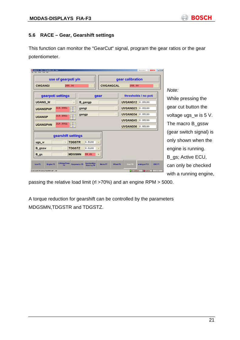
5.6 RACE – Gear, Gearshift settings
This function can monitor the “GearCut“ signal, program the gear ratios or the gear
potentiometer.
Note:
While pressing the
gear cut button the
voltage ugs_w is 5 V.
The macro B_gssw
(gear switch signal) is
only shown when the
engine is running.
B_gs; Active ECU,
can only be checked
with a running engine,
passing the relative load limit (rl >70%) and an engine RPM > 5000.
A torque reduction for gearshift can be controlled by the parameters
MDGSMN,TDGSTR and TDGSTZ.
22
MODAS-DISPLAYS FIA-F3
migs w
time
MDGSMN
TDGSTZ
TDGSTR
B_gs = true
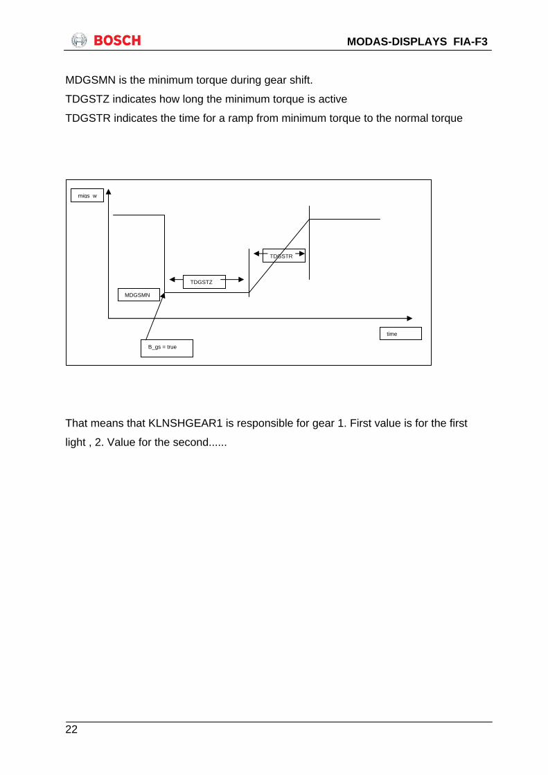
MDGSMN is the minimum torque during gear shift.
TDGSTZ indicates how long the minimum torque is active
TDGSTR indicates the time for a ramp from minimum torque to the normal torque
That means that KLNSHGEAR1 is responsible for gear 1. First value is for the first
light , 2. Value for the second......

23
MODAS-DISPLAYS FIA-F3
5.7 RACE – Gear
In this display the gear ratios are calculated and the gear poti can be tuned. These
features are used for the gear switch function. The thresholds are calculated as a
function of: vfzg/nmot.
Example: 5 speed gear box.
Gear 1 2 3 4 5
Vehicle speed at 6000rpm [km/h] 80 120 160 200 240
Calculated gear ratio (vfzg/nmot) 0,013 0,02 0,026 0,033 0,04
Programmed shift ratio: UVGANG12 = 0,0166
UVGANG23 = 0,0234
UVGANG34 = 0,03
UVGANG45 = 0,0366
The codeword
CWGANGI is used to
tune whether a gear
poti is attached or if
the gear position is
calculated via gear
ratios.
(=1 gear poti attached,
=0 gear pos. calcu-
lated by gear ratios).
UGANGMX and
UGANGMN are
thresholds used for diagnostics of the gear poti.
UGANGP is used to tune the gear poti itself. This is done by moving the gear leaver
into the gear position that should be detected and reading the voltage
(ugang_w) for this gear. This value needs to be written in UGANGP.
UGANGPHP and UGANGPHN are tuneable thresholds and indicate the min. and
max. voltage within a gear is detected. These thresholds can be tuned for each gear
individually.

24
MODAS-DISPLAYS FIA-F3
To adjust a new gearposition (after the gearbox was open), it is just necessary to
switch the codeword CWGANGCAL from 0 to 1 and back to 0 again. During the
adjustment it is absolutely necessary that you are in the 1. Gear !!!!!!

25
MODAS-DISPLAYS FIA-F3
6 ASCII – Decimal – Table
Dec ASCII Dec ASCII Dec ASCII Dec ASCII 0 NUL 32 SP 64 @ 96 ' 1 SOH 33 ! 65 A 97 a 2 STX 34 „ 66 B 98 b 3 ETX 35 # 67 C 99 c 4 EOT 36 $ 68 D 100 d 5 ENQ 37 % 69 E 101 e 6 ACK 38 & 70 F 102 f 7 BEL 39 ' 71 G 103 g 8 BS 40 ( 72 H 104 h 9 HT 41 ) 73 I 105 i
10 LF 42 * 74 J 106 j 11 VT 43 + 75 K 107 k 12 FF 44 , 76 L 108 l 13 CR 45 - 77 M 109 m 14 SO 46 . 78 N 110 n 15 SI 47 / 79 O 111 o 16 DLE 48 0 80 P 112 p 17 DC1 49 1 81 Q 113 q 18 DC2 50 2 82 R 114 r 19 DC3 51 3 83 S 115 s 20 DC4 52 4 84 T 116 t 21 NAK 53 5 85 U 117 u 22 SYN 54 6 86 V 118 v 23 ETB 55 7 87 W 119 w 24 CAN 56 8 88 X 120 x 25 EM 57 9 89 Y 121 y 26 SUB 58 : 90 Z 122 z 27 ESC 59 ; 91 [ 123 { 28 FS 60 < 92 \ 124 | 29 GS 61 = 93 ] 125 } 30 RS 62 > 94 ^ 126 ~ 31 US 63 ? 95 _ 127 DEL

26
MODAS-DISPLAYS FIA-F3
7 CDT – error list
Failure path Label codeword
Identifier-Nr
1 CDTATS codeword tester exhaust temperature sensor
2 CDTATS2 codeword tester exhaust temperature sensor bank 2
3 CDTBM code word tester: reference mark sensor
4 CDTDK code word tester: throttle position potentiometer
5 CDTDK1P code word tester: Throttle Position Poti 1
6 CDTDK2P code word tester: Throttle Position Poti 2
7 CDTDSCNK code word tester: crankcase pressure sensor
8 CDTDSFUE code word tester: fuel pressure sensor
9 CDTDSL code word tester: pressure sensor charging pressure
10 CDTDSOE code word tester: oil pressure sensor
11 CDTDSS code word tester: Manifold absolute pressure
12 CDTDSU code word tester: Pressure Sensor Ambient
13 CDTDSVLU code word tester: pressure sensor comparison (load/
ambient pressure)
14 CDTEV1 code word tester: injection valve of cyl. 1
15 CDTEV2 code word tester: injection valve of cyl. 2
16 CDTEV3 code word tester: injection valve of cyl. 3
17 CDTEV4 code word tester: injection valve of cyl. 4
18 CDTEV5 code word tester: injection valve of cyl. 5
19 CDTEV6 code word tester: injection valve of cyl. 6
20 CDTGSH code word tester: request of gear shift function
21 CDTHSV code word tester: oxygen sensor heater upstream
catalyst
22 CDTKPE code word tester: fuel pump relay power stage
23 CDTKRNT code word tester: knock control zero test pulse [220]
24 CDTKROF code word tester: knock control offset
25 CDTKRTP code word tester: knock control test pulse
26 CDTKS1 code word tester: knock sensor 1
27 CDTKS2 code word tester: knock sensor 2
28 CDTKS3 code word tester: knock sensor 3

27
MODAS-DISPLAYS FIA-F3
29 CDTKS4 code word tester: knock sensor 4
30 CDTLAP code word tester: lap trigger signal
31 CDTLM code word tester: air-flow sensor/hot-wire air-flow
meter
32 CDTLSV code word tester: lambda sensor upstream catalyst
[010]
33 CDTMILE code word tester: MIL power stage
34 CDTN code word tester: speed pick up
35 CDTOLLAE code word tester: oil warning lamp powerstage
36 CDTPH code word tester: phase sensor
37 CDTSHLAE code word tester: shift lamp powerstage
38 CDTTA code word tester: intake-air temperature
39 CDTTFUEL code word tester: fuel temperature
40 CDTTM code word tester: engine temperature
41 CDTTOL code word tester: oil temperature
42 CDTTUM code word tester: ambient (-air) temperature
43 CDTUB code word tester: power supply voltage UB
44 CDTVFZ code word tester: vehicle speed signal

Bosch Engineering GmbHMotorsport
An der Bracke 971706 Markgröningen
Germany
Phone: 00 49 (0) 711/811-3981Fax: 00 49 (0) 711/811-3982
North American Office:Robert Bosch Corporation
Motorsport, Dep. AP/EAP38000 Hills Tech Drive
Farmington Hills, MI 48331-3417Phone: 00 1 248 848-2977Fax: 00 1 248 324-7373
E-mail: [email protected]