modbus communication contents - schneider electric 5 seped310017en - 01/2013 modbus communication...
TRANSCRIPT

271
5
SEPED310017EN - 01/2013
Modbus Communication Contents
Presentation 272
Managing the Modbus protocol 273
Configuring the communication interfaces 274Serial line communication 274
Ethernet communication 276
Commissioning and diagnosis 280Serial line communication 280
Ethernet communication 282
Data addresses and coding 287
Addresses in direct-access mode 289
Time-setting and synchronization 308
Time-tagged events 310
Transferring records 312
Access to remote settings 315
Customized table 317
Security 318
Reading Sepam identification 319
Appendix 1. Modbus protocol 320
Appendix 2. Function settings 325

272
5
SEPED310017EN - 01/2013
Modbus communication Presentation
GeneralModbus communication allows Sepam to be connected to a supervisor or any other
device with a master Modbus communication channel.
Sepam is always a slave station.
Sepam series 60 is equipped with:
b 1 port C1 (COM1) to connect the serial communication interfaces,
b 1 port F to connect the Ethernet communication interfaces.
The interfaces to connect Sepam to a single serial network are the following:
b ACE949-2, for connection to a 2-wire RS 485 network
b ACE959, for connection to a 4-wire RS 485 network
b ACE937, for connection to a fiber-optic star network
The interfaces to connect Sepam to 2 serial networks are the following:
b ACE969TP-2, for connection to:
v one 2-wire RS 485 Modbus S-LAN supervision communication network
v one 2-wire RS 485 E-LAN engineering communication network
b ACE969FO-2, for connection to:
v one fiber-optic Modbus S-LAN supervision communication network
v one 2-wire RS 485 E-LAN engineering communication network
The interfaces to connect Sepam to an Ethernet network are the following:
b ACE850TP for copper electrical connection to the network
b ACE850FO for optical connection to the network.
Accessing Sepam dataData availableModbus communication provides access to many different functions, including:
b reading of metering and diagnosis information
b reading of status conditions and remote indications
b transfer of time-tagged events
b transfer of files such as disturbance recordings and tripping contexts and, for
Sepam series 60, out-of-sync contexts, motor start reports, motor start trends and
data logs
b viewing of protection settings
b reading of Sepam configuration and identification
b remote control of the analog output
b time-setting and synchronization.
The actual list depends on the application, the type of Sepam and the enabled
functions.
Modbus communication also offers a number of additional functions (when enabled):
b transmission of remote controls
b modification of protection settings.
A password may be set up to protect access to these two functions.
Access modesDepending on the data, two access modes are used:
b direct access - the data may be accessed directly in a single read or write
operation
b indirect access - access requires a number of read and write operations, using a
protocol that is specific to the data accessed.
Customized tableWith Sepam, it is possible to set up for each Modbus port a customized sub-group of
data for quick reading of the most significant information on the user application.
Compatibility with Sepam 2000Even though Sepam series 60 offers many additional functions, it remains
compatible with Sepam 2000 addresses and formats for most information.

273
5
SEPED310017EN - 01/2013
Modbus communication Managing the Modbus protocol
Protocol operationModbus is used to exchange information between a master and one or more slave
units, identified by a number. It implements request-reply dialog, where requests are
always initiated by the master. Modbus exists in ASCII and binary (RTU mode)
formats.
Data is exchanged in the form of 16-bit words (also called registers) or simply bits.
Each piece of information (bit or register) has a 16-bit address.
A detailed description of the protocol is provided in the appendix. It may also be found
at www.modbus.org.
Modbus functions The Modbus protocol used by Sepam series 60 is a compatible sub-group of the RTU
Modbus protocol.
The functions listed below are handled by Sepam series 60:
b basic functions (data access):
v function 1: reading of n output or internal bits
v function 2: reading of n input bits
v function 3: reading of n output or internal words
v function 4: reading of n input words
v function 5: writing of 1 bit
v function 6: writing of 1 word
v function 7: high-speed reading of 8 bits
v function 15: writing of n bits
v function 16: writing of n words.
b communication-management functions:
v function 8: Modbus diagnosis
v function 11: reading of Modbus event counter
v function 43: sub-function 14: reading of identification.
b enhanced functions:
v function 102: secure access.
The following exception codes are supported:
b 1: unknown function code
b 2: incorrect address
b 3: incorrect data
b 4: not ready (cannot process request)
b 7: not acknowledged (remote reading and setting in particular).
Multi-master operation
Serial line Modbus operationWhen Sepam units are connected via a gateway to a multiple-access network
(Ethernet, Modbus+, etc.), a number of masters may address the same unit via the
serial communication port.
The serial line Modbus protocol cannot manage this type of architecture. The
network designer is responsible for avoiding collisions.
b For direct-access data, in general, no particular precautions must be taken.
b For indirect-access data, Sepam provides two exchange zones, making possible
2 simultaneous, independent accesses by 2 different masters.
Modbus over TCP/IP operationThe ACE850 accepts up to 8 simultaneous Modbus/TCP connections.
Sepam accepts the Unit-Id 255 or any value in the range 1-247.
If several clients are accessing indirect-access data, they must make proper use of
the two exchange zones provided. No access synchronization is provided by Sepam
units.
PerformanceThe typical response time (time between the end of request reception and sending
the reply) is less than 10 milliseconds for 90% of exchanges.
It may occasionally be longer, but not exceed 150 ms.
In indirect mode, the time needed between the request (or an acknowledgment) and
the availability of the corresponding data is linked to the Sepam low-priority cycle
time and may vary from a few dozen to several hundred milliseconds.

274
5
SEPED310017EN - 01/2013
Modbus communication Configuring the communication interfacesSerial line communication
PE
80
77
6
Access to configuration parametersThe Sepam communication interfaces must be configured using SFT2841 software.
The configuration parameters can be accessed from the Communication
configuration window in the SFT2841 software.
To access this window:
b open the Sepam configuration window in SFT2841
b check the COM1 box
b click on the relevant button : the Communication configuration window
appears
b select the type of interface used: ACE949/ACE959/ACE937, ACE969TP or
ACE969FO
b select the Modbus communication protocol.
The configuration parameters will vary depending on the communication interface
selected: ACE949/ACE959/ACE937, ACE969TP or ACE969FO. The table below
specifies the parameters to be configured depending on the communication interface
chosen.
SFT2841: Sepam configuration screen.
Parameters to be configured ACE949ACE959ACE937
ACE969TP ACE969FO
Physical layer parameters b b b
Fiber-optic parameters b
Advanced Modbus parameters b b b
E-LAN parameters b b
PE
50
56
1
SFT2841: communication configuration window for ACE949.
Configuring the physical layer of the Modbus
portAsynchronous serial transmission is used with the following character format:
b 1 start bit
b 8 data bits
b 1 stop bit
b parity according to parameter setting.
The number of stop bits is always fixed at 1.
If a configuration with parity has been selected, each character will contain 11 bits:
1 start bit + 8 data bits + 1 parity bit + 1 stop bit.
If a no parity configuration has been selected, each character will contain 10 bits:
1 start bit + 8 data bits + 1 stop bit.
The configuration parameters for the physical layer of the Modbus port are as
follows:
b slave number (Sepam address)
b transmission speed
b parity check type.
Parameters Authorized values Default value
Sepam address 1 to 247 1
Speed 4800, 9600, 19200or 38400 bps
19200 bps
Parity No parity, even or odd
Even
Configuring the ACE969FO-2 fiber-optic portThe configuration for the physical layer of the ACE969FO-2 fiber-optic port is
completed with the following 2 parameters:
b link idle state: light-on or light-off
b echo mode: with or without.
Fiber-optic parameters Authorized values Default value
Link idle state Light Off or Light On Light Off
Echo mode Yes (fiber-optic ring) or No (fiber-optic star)
No
Note: in echo mode, the Modbus master will receive the echo of its own request before the slave's reply. The Modbus master must be able to disregard this echo. Otherwise, it is impossible to create a Modbus fiber-optic ring.

275
5
SEPED310017EN - 01/2013
Modbus communication Configuring the communication interfacesSerial line communication
PE
50
55
9
Configuring Modbus advanced parametersWith Sepam series 60, remote controls and remote settings can be protected by a
password.
Advanced parameters can be used to configure the security function by:
b activating the function
b entering the password for the remote controls
b entering the password for the remote settings.
Advanced parameters Authorized values Default value
Security function On/Off Off
Remote controls password 4-digit code 0000
Remote settings password 4-digit code 0000
Modbus Advanced parameters window.
PE
50
56
0
Configuring the physical layer of the
ACE969-2 E-LAN portThe E-LAN port on the ACE969TP-2 and ACE969FO-2 communication interfaces is
a 2-wire RS 485 port.
The configuration parameters for the physical layer of the E-LAN port are:
b Sepam address
b transmission speed
b parity check type.
The number of stop bits is always fixed at 1.
If a configuration with parity has been selected, each character will contain 11 bits:
1 start bit + 8 data bits + 1 parity bit + 1 stop bit.
If a no parity configuration has been selected, each character will contain 10 bits:
1 start bit + 8 data bits + 1 stop bit.
Parameters Authorized values Default value
Sepam address 1 to 247 1
Speed 4800, 9600, 19200or 38400 bps
38400 bps
Parity No parity, even or odd
Odd
Configuration tipsb The Sepam address MUST be assigned before Sepam is connected to the
communication network.
b You are also strongly advised to set the other physical layer configuration
parameters before connecting to the communication network.
b Modifying the configuration parameters during normal operation will not disturb
Sepam but will reset the communication port.
Communication configuration window for ACE969FO.

276
5
SEPED310017EN - 01/2013
Modbus communication Configuring the communication interfacesEthernet communication
Access to configuration parameters
PE
80
77
6
The Sepam communication interfaces must be configured using SFT2841 software.
The configuration parameters can be accessed from the Communication
configuration window in the SFT2841 software.
To access this window:
b open the Sepam configuration window in SFT2841
b select the Ethernet communication port
b click on the relevant button : the Communication configuration window
appears
b select the type of interface used: ACE850TP or ACE850FO.
Configuring an ACE850 involves:
b configuring the standard Ethernet parameters (mandatory)
b configuring one or more of the following sets of advanced optional parameters:
v SNMP: Ethernet network management
v SNTP: time synchronization
v IP filtering: access control
v RSTP: Ethernet ring management
v User accounts: access control.
SFT2841: Sepam configuration screen.
Ethernet and TCP/IP configurationBefore configuring the ACE850, obtain a unique static IP address, subnet mask, and
default gateway address from the network administrator. See the section on
IP address and parameter guidelines, page 279.PE
80
39
5
Parameters Description Authorized values
Frame format Used to select the format for data sent over an Ethernet connection.
Ethernet II, 802.3, AutoDefault: Ethernet II
Media type Used to define the physical Ethernet connection.
ACE850TPb 10T/100Tx Autob 10BaseT-HDb 10BaseT-FDb 100BaseTX-HDb 100BaseTX-FDDefault: 10T/100Tx Auto
ACE850FOb 100BaseFX-HDb 100BaseFX-FDDefault: 100BaseFX-FD
IP address Used to enter the static IP address of the ACE850.
0.0.0.0 to 255.255.255.255Default: 169.254.0.10
Subnet mask Used to enter the subnet mask of your network.
0.0.0.0 to 255.255.255.255Default: 255.255.0.0
Default gateway Used to enter the default gateway (router) IP address used for wide area network (WAN) communications.
0.0.0.0 to 255.255.255.255Default: 0.0.0.0
SFT2841 : Ethernet and TCP/IP communication configuration screen.
Allow CID file tooverride IP parameters
This option is irrelevant when only Modbus communication is used.
Default: not checked
Keep alive Timeout value used to test for session disconnection.
1 to 60 secondsDefault: 30 seconds
FTP session inactivity timeout
Timeout value used to force disconnection of an inactive FTP session
30 to 900 secondsDefault: 30 seconds
Duplicate IP address detectionThe ACE850 IP address must be unique in the network. If it is not unique, the Status
LED repeats a four blink-pause pattern and a new IP address must be assigned to
the ACE850 or to the conflicting device.

277
5
SEPED310017EN - 01/2013
Modbus communication Configuring the communication interfacesEthernet communication
SNMP configurationThe ACE850 supports SNMP V1, allowing a network administrator to remotely
access it with an SNMP manager and view the network status and diagnostics in
the MIB2 format (only a subset of MIB2 is implemented).
Additionally, the ACE850 may be configured to send SNMP traps in the following
cases:
b ACE850 start/restart
b Link up
b Link down
b Authentication failure.
PE
80
39
6
Parameters Description Authorized values
System Name This parameter is the same as the Sepam label.
Not modifiable from this screen.
System Contact Name of the administrative contact String (< 16 characters) Default: empty string
SFT2841: SNMP configuration. System Location Location of the Sepam/ACE850 String (< 16 characters)Default: empty string
Read-onlyCommunity Name
SNMP community that has read-onlyaccess to the MIB. Acts as a password.
String (< 16 characters)Default: "public"
Read-writeCommunity Name
SNMP community that has read-writeaccess to the MIB. Acts as a password.
String (< 16 characters)Default: "private"
Enable traps Checking this check box enables SNMP to send traps.
Default: "not checked"
TrapsCommunity Name
SNMP community that is used with traps. String (< 16 characters)Default: "public"
Manager 1 IP address
IP address of the SNMP manager to which traps are sent.
0.0.0.0 to 255.255.255.255Default: 0.0.0.0
Manager 2 IP address
IP address of a second SNMP manager to which traps are sent.
0.0.0.0 to 255.255.255.255Default: 0.0.0.0
SNTP configurationSNTP is a time synchronization protocol that can be used to synchronize the
Sepam. SNTP is used in mode 3-4 (unicast mode).
b If SNTP is used, the synchronization source for Sepam must be defined as
Ethernet.
b If SNTP is not used, the Sepam synchronization must be ensured by other
means (Modbus frames, synchronization tops).
PE
80
39
7
Parameters Description Authorized values
Enable SNTP Enables the time and date of the Sepam to be set by the Simple Network Time Protocol (SNTP) server.
Default: not enabled
Time Zone Offset Determines the difference between local time and Coordinated Universal Time (UTC) (same as GMT).
UTC-12 to UTC+14Default: UTC
Enable DaylightSaving Time
Enables the use of Daylight Saving Time (Summer time).
Default: not enabled
SFT2841: SNTP configuration. DST offset Difference between standard time andDaylight Saving Time.
+ 30 or + 60 minutesDefault: + 60 minutes
DST starts If enabled, DST starts on the selected date.
Default: last Sunday of March
DST ends If enabled, DST ends on the selected date. Default: last Sunday of October
Primary Server IP Address
The IP address of the SNTP server the ACE850 contacts to get the time message.
0.0.0.0 to 255.255.255.255Default: 0.0.0.0
Secondary Server IP Address
The IP address of another SNTP server the ACE850 contacts in case the primary server is down.
0.0.0.0 to 255.255.255.255Default: 0.0.0.0
Poll Interval Controls how often the ACE850 contacts the SNTP server for the correct time.
1 to 300 minutesDefault: 60 minutes

278
5
SEPED310017EN - 01/2013
Modbus communication Configuring the communication interfacesEthernet communication
IP filtering configurationThe IP filtering function allows the administrator to specify which Modbus/TCP
clients and which IEC 61850 clients have access to the ACE850 services.
Note: if IP filtering is enabled, access is forbidden to any client not in the filtered list. PE
80
39
8
Parameters Description Authorized values
Enable filtering Check this box to activate filtering based on IP addresses.
Default: not enabled
IP address The IP address of a client for which filtering options are defined.
0.0.0.0 to 255.255.255.255Default: 0.0.0.0
IEC 61850 Check this box to grant IEC 61850 access to the given IP address.
Default: not checked
Modbus Check this box to grant Modbus/TCP access to the given IP address.
Default: not checked
SFT2841: IP filtering configuration.
RSTP configurationThe RSTP protocol enables the use of redundant Ethernet architectures such as
rings.
It must be enabled each time the ACE850 is included in a loop. It may be disabled
in other cases.
Changing the default settings is normally not required and should be performed with
extreme care as it could jeopardize the stability of the Ethernet network.
If in doubt, it is always possible to revert to the default values using the Default
settings button.
PE
80
39
9
Parameters Description Authorized values
Enable RSTP Check this box to activate the use of the RSTP protocol.
Default: enabled
RSTP bridge priority Priority of the RSTP bridge. The bridge with the lowest priority becomes root.
0 - 61440, by steps of 4096Default: 61440
Hello time Amount of time between the transmission of configuration messages
1 to 10 secondsDefault: 2 seconds
SFT2841: RSTP configuration. Forward delay time Time value to control how fast a port changes its spanning state when moving towards the forwarding state
4 to 30 secondsDefault: 21 seconds
Max age time Valid duration of configuration message once sent by the root bridge
6 to 40 secondsDefault: 40 seconds
Max transmit count Maximum BPDUs that can be transmitted by the Port Transmit state machine in any Hello time. This value limits the maximum transmission rate.
3 to 100Default: 32
RSTP cost style RSTP (32 bits) or STP (16 bits) cost style selection
Default: RSTP
Note: RSTP parameters must verify the following relationships:b 2 x (Forward_delay_time - 1 second) u Max_age_timeb Max_age_time u 2 x (Hello_time + 1 second).

279
5
SEPED310017EN - 01/2013
Modbus communication Configuring the communication interfacesEthernet communication
User accounts configurationACE850 users are assigned usernames and passwords used to gain access to the
FTP or WEB servers. Each user belongs to a group which determines the user’s
access rights:
b Administrator: read-write access to the FTP server, access to the WEB server
b Operator: read-only access to the FTP server, access to the WEB server
b Guest: no access to the FTP server, access to the WEB server
Up to 4 user accounts can be defined.
PE
80
40
0
Parameters Description Authorized values
User control enable Check this box to enable the configuration of users account. Currently, the ACE850 will not operate if this box is not checked. Ensure that this box is always checked.
Default: enabled
User n Check this box to create this user account. Uncheck it to delete the account (only the last account in the list can be deleted).
Default: user 1 enabledUsers 2 to 4 disabled
SFT2841: User accounts configuration. Name User name String (1 to 8 characters)
Password User password String (4 to 8 characters)
Group Group to which the user belongs Administrator, Operator, Guest
The following account is always created by default as user 1:
b Name: Admin
b Password: ACE850
b Group: Administrator
IP address and parameter guidelines
IP addressesSeveral configuration parameters are IP addresses. These addresses must follow
precise rules which are enforced by SFT2841 and ACE850. These rules are:
b Every IP address is made of 4 fields separated by dots: x . y . z . t
b Each field is a decimal value coded on 8 bits (range [0..255]).
b The first field (x) must be in the range [1..224] but must not be 127.
b Intermediate fields can cover the full range [0..255].
b The last field must not be 0 (range [0..255]).
IP subnet maskThe IP subnet mask is also made of 4 dot separated fields:
b The binary representation of the subnet mask is made of a set of 8 to 30
contiguous ones in the most significant part, followed by a set of contiguous zeroes
(255.0.0.0 to 255.255.255.252).
b For a class A IP address (x y 126), the number of ones in the subnet mask must
be at least 8 (255.y.z.t).
b For a class B IP address (128 y x y 191), the number of ones in the subnet mask
must be at least 16 (255.255.z.t).
b For a class C IP address (192 y x y 223), the number of ones in the subnet mask
must be at least 24 (255.255.255.t).
b The subnet part of the device IP address, obtained when applying the subnet
mask, must not be 0.
IP default gatewayb An IP address of 0.0.0.0 means no gateway.
b If a gateway is defined, it must belong to the same subnet as the device.

280
5
SEPED310017EN - 01/2013
Modbus communication Commissioning and diagnosisSerial line communication
Installing the communication network
Preliminary studyAccording to the installation characteristics and constraints, a technical study must
first determine the communication network requirements, including:
b the type of medium (electrical or fiber optic)
b the number of Sepam units per network
b the transmission speed
b the ACE interfaces configuration
b the Sepam parameter settings.
Sepam operating instructionsCommunication interfaces must be installed and connected in accordance with the
Installation chapter of this manual.
Preliminary checksPerform the following:
b check the CCA612 cord connection between the ACE interface and the Sepam
base unit
b check the ACE Modbus communication port connection
b check the complete configuration of the ACE
b for the ACE969, check the auxiliary power supply connection.
PE
80
77
7
Checking the operation of the ACE interfaceYou can use the following to check that an ACE interface is operating correctly:
b the indicator LEDs on the front panel of the ACE
b the information provided by the SFT2841 software connected to Sepam:
v on the Diagnosis screen
v on the Communication configuration screens.
Link activity LED for ACE949-2, ACE959 and ACE937The link activity LED for ACE949-2, ACE959 and ACE937 interfaces flashes when
Sepam transmission or reception is active.
Indicator LEDs on the ACE969b green "on" LED: ACE969 energized
b red "key" LED: ACE969 interface status:
v LED off: ACE969 configured and communication operational
v LED flashing: ACE969 configuration error or ACE969 not configured
v LED on: ACE969 error
b S-LAN and E-LAN Tx/Rx LEDs:
v Tx flashing: Sepam transmitting
v Rx flashing: Sepam receiving
v Tx and Rx off: RS 485 communication is idle
v Tx or Rx LED on while the RS485 communication network is idle: the idle state
voltage of the RS485 network is incorrect.
SFT2841: Sepam series 60 diagnosis screen.
PE
80
41
7
Diagnosis using SFT2841 software
Sepam diagnosis screenWhen connected to Sepam, the SFT2841 software informs the operator of the
general Sepam status and of the Sepam communication status in particular.
The Sepam diagnosis screen displays Sepam status information. You can get
detailed status information about each communication channel using buttons on the
screen.
Sepam communication diagnosisThe operator is provided with the following information to assist with identifying and
resolving communication problems:
b name of the protocol configured
b Modbus interface version number
b number of valid frames received (CPT9)
b number of invalid (mistaken) frames received (CPT2).SFT2841: Communication diagnosis.

281
5
SEPED310017EN - 01/2013
Modbus communication Commissioning and diagnosisSerial line communication
Link activity LEDThe ACE interface link activity LEDs are activated by
variations in the signal on the Modbus network. When
the supervisor communicates with Sepam (during
transmission or reception), these LEDs flash.
After wiring, check the information given by the link
activity LEDs when the supervisor operates.
Note: flashing indicates that there is traffic passing to or from Sepam; it does not mean that the exchanges are valid.
Functional testIf there is any doubt about correct operation of the link:
b run read/write cycles in the test zone
b use Modbus diagnosis function 8 (sub-code 0, echo
mode).
The Modbus frames below, transmitted or received by
a supervisor, are an example of a test performed when
communication is implemented.
Modbus diagnosis counters
Counter definitionSepam manages the Modbus diagnosis counters. These are:
b CPT1: Number of valid frames received, whether the slave is involved or not
b CPT2: Number of frames received with a CRC error or physical error (frames with
more than 255 bytes, frames received with at least one parity, overrun, framing or
line-break error)
b CPT3: Number of exception responses generated (even if not transmitted, due to
receipt of a broadcast request)
b CPT4: Number of frames specifically addressed to the station (excluding
broadcasting)
b CPT5: Number of valid broadcast frames received
b CPT6: Not significant
b CPT7: Not significant
b CPT8: Number of frames received with at least one character having a physical
error (parity, overrun, framing or line break)
b CPT9: Number of valid requests received and correctly executed.
Counter resetThe counters are reset to 0:
b when they reach the maximum value FFFFh (65535)
b when they are reset by a Modbus command (function 8)
b when Sepam auxiliary power is lost
b when communication parameters are modified.
Using the countersModbus diagnosis counters help to detect and resolve communications problems.
They can be accessed by the dedicated read functions (Modbus protocol functions
8 and 11).
The CPT2 and CPT9 counters can be displayed on SFT2841 ("Sepam Diagnosis" screen).
An incorrect speed (or parity) increments CPT2.
Non-reception is signaled by the lack of change on CPT9.
Operating anomaliesIt is advisable to connect the Sepam units to the Modbus network one by one.
Make sure that the supervisor is sending frames to the relevant Sepam by checking
the activity on the RS 232 - RS 485 converter or the fiber-optic converter if there is
one, and on the ACE module.
RS 485 networkb check the wiring on each ACE module
b check the tightness of the screw terminals on each ACE module
b check the connection of the CCA612 cord linking the ACE module to the Sepam
base unit
b check that polarization is only at one point and that impedance matching is at both
ends of the RS 485 network
b check the auxiliary power supply connection to the ACE969TP-2
b check that the ACE909-2 or ACE919 converter used is connected, powered and
set up correctly.
Fiber-optic networkb check the connections on the ACE module
b check the connection of the CCA612 cord linking the ACE module to the Sepam
base unit
b check the auxiliary power supply connection to the ACE969FO-2
b check that the converter or fiber-optic star used is correctly connected, powered
and configured
b for a fiber-optic ring, check that the Modbus master can correctly handle the echo
of its requests.
In all casesb check all the ACE configuration parameters on SFT2841
b check the CPT2 and CPT9 diagnostic counters on SFT2841
("Sepam Diagnosis" screen).
Test zone
Read Transmission 01 03 0C00 0002 C75B
Reception 01 03 04 0000 0000 FA33
Write Transmission 01 10 0C00 0001 02 1234 6727
Reception 01 10 0C00 0001 0299
Read Transmission 01 03 0C00 0001 B75A
Reception 01 03 02 1234 B539
Function 8 - Modbus diagnosis, echo mode
Transmission 01 08 0000 1234 ED7C
Reception 01 08 0000 1234 ED7C
Even in echo mode, Sepam recalculates and checks
the CRC sent by the master:
b if the CRC received is valid, Sepam replies
b if the CRC received is invalid, Sepam does not reply.

282
5
SEPED310017EN - 01/2013
Modbus communication Commissioning and diagnosisEthernet communication
Installing the Ethernet network
Preliminary studyAccording to the installation characteristics and constraints, a technical study must
first determine the Ethernet network requirements, including:
b the network topology
b the various subnets (if any) and their interconnections
b the IP addressing scheme
Sepam operating instructionsCommunication interfaces must be installed and connected in accordance with the
instructions of the Installation chapter of this manual and with the instruction sheet
delivered with each ACE850 communication interface (reference BBV35290).
Preliminary checksPerform the following actions:
b check the CCA614 cord connection between the ACE850 interface and the
Sepam base unit
b check the connection of the ACE850 to the Ethernet network
b check the auxiliary power supply connection
b check the complete configuration of the ACE850.
Checking the operation of the ACE850
interfaceYou can use the following to check that an ACE850 interface is operating correctly:
b the indicator LEDs on the front panel of the ACE850
b the information provided by the SFT2841 software connected to Sepam
b the Web pages embedded inside the ACE850.
Basic diagnostics
Diagnosis using indicator LEDs on the ACE8501 On/fault indicator. This indicator has the following states:
b Off: the ACE850 interface is not powered
b steady red: the ACE850 is initializing or is faulty
b blinking red: the ACE850 is unable to establish communication with the Sepam
base unit, or the ACE850 is not properly configured
b steady green: the ACE850 is operating correctly
b fast blinking green: indicates a transient state which occurs at startup when IEC
61850 communication is also used
b steady green and blinking red: communication with the base unit has been lost.
This can indicate a normal situation due to a restart of the Sepam after parameters
have been downloaded. The ACE850 automatically resumes normal operation in a
few seconds.
This status can also indicate an error condition, in which case, ACE850 restarts
automatically within 15 seconds and try to re-establish connection.
2 Status indicator. This indicator has the following states:
b Off: the Ethernet communication is not started
b steady green: the Ethernet communication is correctly operating
b three blinks pattern: no logical Ethernet link
b four blinks pattern: duplicate IP address
b six blinks pattern: invalid IP configuration.
3 and 5 Speed indicators. These indicators have the following states:
b Off: the corresponding physical link is down or the port speed is 10Mbps
b On: the corresponding port operates at 100Mbps.
4 and 6 Link/Activity indicators. These indicators have the following states:
b Off: the corresponding physical link is not established
b On: the corresponding physical link is established
b blinking: the indicator blinks with the activity on the link.
DE
80
43
2
ACE850 communication interface.
ACE850FO
FS80
100BASE- FX
CS40
P2 P1
100BASE- FX
Tx Rx Tx Rx
Sepam
1
23456

283
5
SEPED310017EN - 01/2013
Modbus communication Commissioning and diagnosisEthernet communication
Diagnosis using SFT2841 softwareWhen connected to Sepam, the SFT2841 software informs the operator of the general
Sepam status and of the Sepam communication status in particular.
Sepam status information appears on the Sepam diagnosis screen on which buttons
can be used to obtain detailed status information on each communication channel.
The Sepam diagnosis screen can be used to check that the Sepam base unit and the
ACE850 interface are correctly connected:
PE
80
77
7
PE
80
40
5
PE
80
40
6
Diagnosis screen detail:ACE850 not or improperly connected.
Diagnosis screen detail:
ACE850 connected properly.
SFT2841: Sepam diagnosis screen.
PE
80
40
2
The Ethernet diagnosis screen can be used to check:
b the ACE850 module status. The ACE850 status is OK if the ACE850 validates its
configuration.
b the communication ports status
b the current ACE850 IP address. If the current IP address is different from the one
configured, this could mean that the configured address is not valid, unless the
IEC 61850 protocol is also being used.
PE
80
64
5
SFT2841: Ethernet diagnosis screen.
Advanced diagnostics using the embedded Web serverThe advanced diagnostics feature is only available when it is possible to establish an
Ethernet connection with the ACE850. If not, the basic diagnostics must be used to
solve the problems.
Accessing the ACE850 Web server1. Start your web browser (Internet explorer 6.0 or higher, Mozilla Firefox for
example).
2. In the address text box, type the address of the ACE850 (169.254.0.10 is the
default), then press Enter.3. In the login window, type your username and password (default is Admin,
ACE850).
4. From the left side menu, choose the language for the current session.
5. From the menu, click Diagnostics to access the diagnostics menu.
Diagnostics Web pagesThere are two general diagnostics pages dealing with Ethernet operation:
b Ethernet global statistics
b Ethernet port statistics
There is also a set of protocol dedicated diagnostic pages:
b Modbus statistics
b IEC 61850 statistics (not covered in this manual)
b SNMP statistics
b SNTP statistics
b RSTP statistics
Diagnostic pages are automatically refreshed every 5 seconds (approximately).
PE
80
40
3
ACE850 home page.

284
5
SEPED310017EN - 01/2013
Modbus communication Commissioning and diagnosisEthernet communication
Ethernet TCP/IP statistics
PE
80
40
4
Item Description
Mac address Unique Ethernet hardware address of the ACE850
Frame type Value of the frame type configured with SFT2841
TCP/IP parameters Parameter values configured with SFT2841
Frames received Total number of received Ethernet frames, regardless of port or protocol
Frames transmitted Total number of transmitted Ethernet frames, regardless of port or protocol
Reset Counters button Button to reset the Ethernet counters
ACE850 Ethernet TCP/IP statistics.
Ethernet port statistics
PE
80
40
7
Item Description
Port P1/P2 buttons Selection of the port of which statistics are displayed
Frames transmitted OK A counter that increments each time a frame is successfully transmitted.
Collisions A counter that increments each time a frame is retransmitted due to collision detection.
Excessive collisions A counter that increments each time a frame cannot be sent because it has reached the maximum collision status based on the Truncated Binary Exponential Backoff algorithm.
Carrier sense errors A counter that increments each time there is a collision because carrier sense is disabled.
ACE850 Ethernet port statistics. Internal MAC Tx errors A counter that increments for every transmission error that is not caused by late, excessive, or carrier sense collisions.
Link speed Actual link speed
Frames received OK A counter that increments each time a frame is successfully received.
Alignment errors A counter that increments each time a received frame has an FCS error and does not end on an 8-bit frame boundary.
CRC errors A counter that increments each time a received frame has a CRC or an alignment error.
FCS errors A counter that increments each time a received frame has a FCS or an alignment error.
Late collisions A counter that increments each time a collision occurs after the slot time (512 bits starting at the preamble).
Reset counters button Button to reset the port counters

285
5
SEPED310017EN - 01/2013
Modbus communication Commissioning and diagnosis Ethernet communication
Modbus/TCP server statistics
PE
80
40
8
Item Description
Port status Modbus port status
Opened TCP connections Number of Modbus clients currently connected
Received messages Total number of Modbus requests
Transmitted messages Total number of Modbus responses
Reset counters button Button to reset the messages counters
Note: the Web interface uses one Modbus connection to operate.
ACE850 Modbus/TCP server statistics.
Modbus/TCP connections statistics
PP
E8
04
09
Item Description
Index Connection number
Remote IP IP address of the Modbus client
Remote port TCP port number on the client side
Local port TCP port number on the server side
Transmitted messages Number of Modbus requests for this connection
Received messages Number of Modbus normal responses for this connection
Sent errors Number of Modbus exception responses for this connection
Reset counters button Button to reset the messages counters
ACE850 Modbus/TCP connections statistics.
SNMP statistics
PE
80
41
0
Item Description
SNMP agent status Status of the SNMP agent
Bad Community usages Number of requests with invalid community
Received messages Total number of SNMP requests
Transmitted messages Total number of SNMP responses
Reset counters button Button to reset the messages counters
ACE850 SNMP statistics.

286
5
SEPED310017EN - 01/2013
Modbus communication Commissioning and diagnosisEthernet communication
SNTP statistics
PE
80
41
1
Item Description
SNTP Client status Value configured for the parameter in SFT2841
Active SNTP server IP address Address of the server currently answering SNTP requests (0.0.0.0 if no server answer)
Poll interval Value configured for the parameter in SFT2841
Round trip delay Total time for SNMP request and response messages
Local offset Difference between SNTP time and ACE time
Daylight saving time Value configured for the parameter in SFT2841
Last Successful Time Synchronization (UTC)
Last time the ACE850 successfully contacted the SNTP server (UTC time)
Device Date and Time (UTC) Current time and date of the ACE850 (UTC time)
Device Date and Time (local) Current time and date of the ACE850 (local time)
ACE850 SNTP statistics.
RSTP bridge statistics
PE
80
41
2
Item Description
Bridge status RSTP status of the bridge
Bridge ID Bridge vector (Bridge priority/Bridge Mac address)
Designated Root ID Bridge vector of the RSTP root bridge
Designated Root Port Identifier of the root port (priority/number)
Rootpath cost Path cost to the root
Total topology changes Topology change counter (as defined by 802.1D-2004)
Configured hello time Value of the configured hello time
Learned hello time Operational value for hello time
Configured forward delay Reminder of the configured forward delay
Learned forward delay Operational value for forward delay
Configured max age Value of the configured max age
Learned max age Operational value for max age
ACE850 RSTP bridge statistics.
RSTP port statistics
PE
80
41
3
Item Description
Port P1 / P2 buttons Selection of the port of which statistics are displayed
Status RSTP status for the selected port
Role RSTP role for the selected port
Priority Port priority
Port path cost Port contribution to root path cost
Designated port ID Identifier of the link partner port (priority/number)
Received RSTs Number of RST BPDUs received (RSTP)
Transmitted RSTs Number of RST BPDUs sent (RSTP)
Received configure Number of Configuration BPDUs received (STP)
Transmitted configure Number of Configuration BPDUs sent (STP)
Received TCNs Number of Topology change BPDUs received (STP)
Transmitted TCNs Number of Topology change BPDUs sent (STP)
ACE850 RSTP port statistics.

287
5
SEPED310017EN - 01/2013
Modbus communication Data addresses and coding
Presentation
Word addressesAll Sepam information accessible via Modbus communication is organized in 16-bit
words. Each word is identified by its address coded on 16 bits, i.e. from 0 to 65535
(FFFFh).
However, to remain compatible with older equipment, the essential information has
addresses coded from 0 to 9999 (270Fh).
In the following pages of this document, all addresses are expressed in hexadecimal
(xxxxh).
Data which is similar from the control-monitoring application and the coding
viewpoint is grouped in adjacent address zones.
Bit addressesSome information is also available in bit form. The bit address is derived from the
word address, where:
bit address = (word address x 16) + bit rank (0 to 15).
Example: word 0C00 bit 0 = C000, word 0C00 bit 14 = C00E.
Non-defined addressesOnly the addresses defined in this document should be used.
If other addresses are used, Sepam may return an exception message or data that
is not significant.
Direct-access dataThis data is permanently identified by its Modbus address. It may be accessed by a
single read or write operation, addressing a part of or the entire zone in question.
Indirect-access dataIn this case, the Modbus addresses indicated make up an exchange zone occupied
by different data, depending on the context. At least two operations are required for
each exchange. The necessary protocol is indicated for each zone.
Data codingExcept where mentioned in the text, Sepam data is coded in one of the formats
below:
b 32S: 32-bit signed 2's complement value
b 32NS: 32-bit non-signed value
b 16S: 16-bit signed 2's complement value
b 16NS: 16-bit non-signed value
b 16O: 16-bit signed value, coded with a shift of 8000h (-32768 is coded 0, 0 is coded
8000h, 32767 is coded FFFFh)
b B: bit or set of bits
b IEC: time coding format using four words as per IEC 60870-5-4:
32-bit formats
For these data, the most-significant word is sent first.
Saturation
In all formats, if a datum overruns the maximum
permissible value for the related format, the value read
for the datum is the maximum permissible value for the
format.
The maximum value can also indicate a non-calculable
value. Bit 15 14 13 12 11 10 9 8 7 6 5 4 3 2 1 0
Word 1 reserved year (0 to 99)
Word 2 0 0 0 0 month (1 to 12) 0 0 0 day (1 to 31)
Word 3 0 0 0 hour (0 to 23) 0 0 minute (0 to 59)
Word 4 millisecond (0 to 59999)
Bits set to 0 correspond to format fields not used by Sepam. They are always read as 0 and are not taken into account during writing.The reserved field is read as 0 and may receive different values during writing.
b ASCII: character string in ASCII code, the number of characters is indicated. When
ASCII strings do not completely fill the field, zero bytes are added. The order of
characters in Modbus words is the following:
v character n in the LSB position
v character n+1 in the MSB position
b MMmm: coding of a version number on 16 bits (major index in the MSB position,
minor index in LSB position)
For 16 and 32 bits values, the following letter may follow the format code:
b A: an out of range or not computable value is indicated by 7FFFh (16-bit) or
00007FFFh (32-bit)
b B: an out of range or not computable value is indicated by 7FFFFFFFh (32-bit)

288
5
SEPED310017EN - 01/2013
Modbus communication Data addresses and coding
List of address zonesStartingaddress
Endingaddress
Accessmode
Accesstype
Time management and Sepam (compatible with Sepam 2000)
Synchronization zone 0002 0005 direct word
Identification zone 0006 000F direct word
Event table (first table compatible with Sepam 2000)
First table 0040 0060 indirect word
Second table 0070 0090 indirect word
Application management
Application zone 0180 01BF direct word
Metering and diagnosis
32-bit metering and diagnosis 0200 02B1 direct word
16-bit metering and diagnosis 0300 0339 direct word
Directories
Disturbance recordings 0400 044F direct word
Tripping context 0480 0497 direct word
Out-of-sync context 0500 0507 direct word
Data log (DLG) 0600 067C direct word
Motor start report (MSR) 0680 06FC direct word
Motor start trend (MST) 0700 077C direct word
Test
Test zone 0C00 0C0F direct word / bit
Status conditions and controls (compatible with Sepam 2000)
Logic/GOOSE inputs and logic equations 0C10 0C19 direct word / bit
Logic outputs 0C20 0C23 direct word / bit
Analog-output control 0C30 0C30 direct word
Remote-control orders 0C84 0C8B direct word / bit
NOTICERemote indications 0C8F 0C9E direct word / bit
First access zone to settings
RISK OF DATA CORRUPTIONWhen using an ACE850 communication interface
with IEC 61850 communication enabled, do not
use the following address zones for Modbus/TCP
(see the list address zone table):
b first access zone to settings
b first zone for recording-data transfer
Failure to follow these instructions can result in equipment damage.
Read settings 2000 207C indirect word
Read request 2080 2080 indirect word
Remote setting 2100 217A indirect word
First zone for recording-data transfer
Selection 2200 2203 indirect word
Read 2300 237C indirect word
Customized table
Data table 2600 267C direct word
Configuration table 2680 26FC direct word
Second access zone to settings (compatible with Sepam 2000)
Read settings D000 D07C indirect word
Read request D080 D080 indirect word
Remote setting D100 D17A indirect word
Second zone for recording-data transfer (compatible with Sepam 2000)
Selection D200 D203 indirect word
Read D300 D37C indirect word
Metering and miscellaneous for Sepam 2000 compatibility
Disturb. rec. identification zone D204 D210 direct word
Measurements x 1 FA00 FA2F direct word
Measurements x 10 FB00 FB24 direct word
Compact zone FB80 FB8F direct word
Configuration zone FC00 FC03 direct word

289
5
SEPED310017EN - 01/2013
Modbus communication Addresses in direct-access mode
PresentationFor each zone, the following data is provided:
b each Modbus address for the zone
b the Modbus function codes available for reading
b the Modbus function codes available for writing
b data formats, values and units
b whether the data can be included in a customized table ("config").
The indicated addresses are always word addresses. For bit access, the bit address
must be used (see above).
Synchronization zoneThe synchronization zone is a data structure containing the absolute data and time
used by Sepam to time-tag its various recordings (events, disturbance recording,
etc.).
Synchronization zone Address Read Write Format Config.
Absolute time (year) 0002 3 16 IEC -
Absolute time (month + day) 0003 3 16 IEC -
Absolute time (hours + minutes) 0004 3 16 IEC -
The zone should be written in a single block containing
4 words, using function 16 (write word).
Absolute time (milliseconds) 0005 3 16 IEC -
Identification zoneThe identification zone contains system information pertaining to the identification
of the Sepam equipment.
Synchronization zone Address Read Write Value/Format
Config.
Manufacturer identification 0006 3 - 0100 -
Equipment identification 0007 3 - 0 -
Marking + equipment type 0008 3 - 1300 -
Modbus version 0009 3 - MMmm -
Application technical level 000A 3 - 1 to n -
version 000B 3 - MMmm -
Sepam check-word 000C 3 - idem 0C8F -
Summary zone 000D 3 - 0 (not mngd) -
Command 000E 3 16 0 (not mngd) -
Extension address 000F 3 - 180 -
This zone is provided to ensure compatibility with existing equipment. A more
complete description is available starting at address 0180 in the application zone or
using the identification read function.
290
5
SEPED310017EN - 01/2013
Modbus communication Addresses in direct-access mode
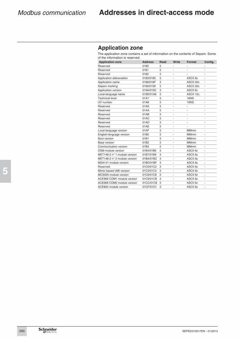
Application zoneThe application zone contains a set of information on the contents of Sepam. Some
of the information is reserved.
Application zone Address Read Write Format Config.
Reserved 0180 3 - - -
Reserved 0181 3 - - -
Reserved 0182 3 - - -
Application abbreviation 0183/0185 3 - ASCII 6c -
Application name 0186/018F 3 - ASCII 20c -
Sepam marking 0190/0199 3 - ASCII 20c -
Application version 019A/019C 3 - ASCII 6c -
Local-language name 019D/01A6 3 - ASCII 12c -
Technical level 01A7 3 - 16NS -
UV number 01A8 3 - 16NS -
Reserved 01A9 3 - - -
Reserved 01AA 3 - - -
Reserved 01AB 3 - - -
Reserved 01AC 3 - - -
Reserved 01AD 3 - - -
Reserved 01AE 3 - - -
Local-language version 01AF 3 - MMmm -
English-language version 01B0 3 - MMmm -
Boot version 01B1 3 - MMmm -
Base version 01B2 3 - MMmm -
Communication version 01B3 3 - MMmm -
DSM-module version 01B4/01B6 3 - ASCII 6c -
MET148-2 n° 1 module version 01B7/01B9 3 - ASCII 6c -
MET148-2 n° 2 module version 01BA/01BC 3 - ASCII 6c -
MSA141 module version 01BD/01BF 3 - ASCII 6c -
Reserved 01C0/01C2 3 - ASCII 6c -
Mimic-based UMI version 01C3/01C5 3 - ASCII 6c -
MCS025 module version 01C6/01C8 3 - ASCII 6c -
ACE969 COM1 module version 01C9/01CB 3 - ASCII 6c -
ACE969 COM2 module version 01CC/01CE 3 - ASCII 6c -
ACE850 module version 01CF/01D1 3 - ASCII 6c -

291
5
SEPED310017EN - 01/2013
Modbus communication Addresses in direct-access mode
32-bit metering and diagnosis zoneThis zone contains all Sepam metering and diagnosis information, coded on 32 bits.
Zone size exceeds the capacity of a frame, i.e. at least two requests are required to
read it in full. Depending on the application and the parameter settings, some
information is not significant.
32-bit metering and diagnosis zone
Address Read Write Format Unit Config.
Phase current I1 0200/0201 3, 4 - 32NS 0.1 A yes
Phase current I2 0202/0203 3, 4 - 32NS 0.1 A yes
Phase current I3 0204/0205 3, 4 - 32NS 0.1 A yes
Residual current I0Σ 0206/0207 3, 4 - 32NS 0.1 A yes
Residual current I0 0208/0209 3, 4 - 32NS 0.1 A yes
Demand current Im1 020A/020B 3, 4 - 32NS 0.1 A yes
Demand current Im2 020C/020D 3, 4 - 32NS 0.1 A yes
Demand current Im3 020E/020F 3, 4 - 32NS 0.1 A yes
Peak demand current IM1 0210/0211 3, 4 - 32NS 0.1 A yes
Peak demand current IM2 0212/0213 3, 4 - 32NS 0.1 A yes
Peak demand current IM3 0214/0215 3, 4 - 32NS 0.1 A yes
Phase-to-phase voltage U21 0216/0217 3, 4 - 32NS 1 V yes
Phase-to-phase voltage U32 0218/0219 3, 4 - 32NS 1 V yes
Phase-to-phase voltage U13 021A/021B 3, 4 - 32NS 1 V yes
Phase-to-neutral voltage V1 021C/021D 3, 4 - 32NS 1 V yes
Phase-to-neutral voltage V2 021E/021F 3, 4 - 32NS 1 V yes
Phase-to-neutral voltage V3 0220/0221 3, 4 - 32NS 1 V yes
Residual voltage V0 0222/0223 3, 4 - 32NS 1 V yes
Positive sequence voltage Vd 0224/0225 3, 4 - 32NS 1 V yes
Negative-sequence voltage Vi 0226/0227 3, 4 - 32NS 1 V yes
Frequency f 0228/0229 3, 4 - 32NSA 0.01 Hz yes
Active power P 022A/022B 3, 4 - 32SB 0.1 kW yes
Reactive power Q 022C/022D 3, 4 - 32SB 0.1 kvar yes
Apparent power S 022E/022F 3, 4 - 32SB 0.1 kVA yes
Power factor cos ϕ 0230/0231 3, 4 - 32SA 0.01 yes
Peak demand active power PM 0232/0233 3, 4 - 32S 0.1 kW yes
Peak demand reactive power QM 0234/0235 3, 4 - 32S 0.1 kvar yes
Active power P phase 1 0236/0237 3, 4 - 32SB 0.1 kW yes
Active power P phase 2 0238/0239 3, 4 - 32SB 0.1 kW yes
Active power P phase 3 023A/023B 3, 4 - 32SB 0.1 kW yes
Reactive power Q phase 1 023C/023D 3, 4 - 32SB 0.1 kvar yes
Reactive power Q phase 2 023E/023F 3, 4 - 32SB 0.1 kvar yes
Reactive power Q phase 3 0240/0241 3, 4 - 32SB 0.1 kvar yes
Apparent power S phase 1 0242/0243 3, 4 - 32SB 0.1 kVA yes
Apparent power S phase 2 0244/0245 3, 4 - 32SB 0.1 kVA yes
Apparent power S phase 3 0246/0247 3, 4 - 32SB 0.1 kVA yes
Positive active energy Ea+ 0248/0249 3, 4 - 32NS 100 kWh yes
Negative active energy Ea- 024A/024B 3, 4 - 32NS 100 kWh yes
Positive reactive energy Er+ 024C/024D 3, 4 - 32NS 100 kvarh yes
Negative reactive energy Er- 024E/024F 3, 4 - 32NS 100 kvarh yes
Ext. positive active energy Ea+ 0250/0251 3, 4 - 32NS 100 kWh yes
Ext. negative active energy Ea- 0252/0253 3, 4 - 32NS 100 kWh yes
Ext. positive reactive energy Er+ 0254/0255 3, 4 - 32NS 100 kvarh yes
Ext. negative reactive energy Er- 0256/0257 3, 4 - 32NS 100 kvarh yes
Neutral-point voltage Vnt 0258/0259 3, 4 - 32NS 1 V yes
Reserved 025A/025F 3, 4 - - - yes

292
5
SEPED310017EN - 01/2013
Modbus communication Addresses in direct-access mode
32-bit metering and diagnosis zone (cont.)32-bit metering and diagnosis zone
Address Read Write Format Unit Config.
Reserved 0260/0267 3, 4 - - - yes
Number of operations 0268/0269 3, 4 - 32NS 1 yes
Tripping current phase 1 Itrip1 026A/026B 3, 4 - 32NS 0.1 A yes
Tripping current phase 2 Itrip2 026C/026D 3, 4 - 32NS 0.1 A yes
Tripping current phase 3 Itrip3 026E/026F 3, 4 - 32NS 0.1 A yes
Tripping current calculated I0 Itrip0 0270/0271 3, 4 - 32NS 0.1 A yes
Reserved 0272/027B 3, 4 - - - yes
Number of operations 027C/027D 3, 4 - 32NS 1 yes
Reserved 027E/027F 3, 4 - - - yes
Reserved 0280/0289 3, 4 - - - yes
Impedance Zd 028A/028B 3, 4 - 32NSB 1 mΩ yes
Impedance Z21 028C/028D 3, 4 - 32NSB 1 mΩ yes
Impedance Z32 028E/028F 3, 4 - 32NSB 1 mΩ yes
Impedance Z13 0290/0291 3, 4 - 32NSB 1 mΩ yes
Reserved 0292/029F 3, 4 - - - yes
Reserved 02A0/02A5 3, 4 - - - yes
Voltage difference dU (synchro-check)
02A6/02A7 3, 4 - 32NSB 0,1 % of Uns Sync1
yes
Frequency difference df (synchro-check)
02A8/02A9 3, 4 - 32NSA 0.001 Hz yes
Phase difference dPhi (synchro-check)
02AA/02AB 3, 4 - 32NSA 0.1° yes
Capacitor capacitance C1(or C21)
02AC/02AD 3, 4 - 32NSB 0.1 µF yes
Capacitor capacitance C2(or C32)
02AE/02AF 3, 4 - 32NSB 0.1 µF yes
Capacitor capacitance C3(or C13)
02B0/02B1 3, 4 - 32NSB 0.1 µF yes
Effective rotation direction 02B2/02B3 3, 4 - 32NSB 0=123 ou 1=132
yes
Reserved 02B4/02FF -
293
5
SEPED310017EN - 01/2013
Modbus communication Addresses in direct-access mode
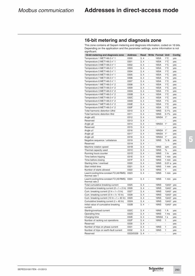
16-bit metering and diagnosis zoneThis zone contains all Sepam metering and diagnosis information, coded on 16 bits.
Depending on the application and the parameter settings, some information is not
significant.
16-bit metering and diagnosis zone Address Read Write Format Unit Config.
Temperature 1 MET148-2 n° 1 0300 3, 4 - 16SA 1°C yes
Temperature 2 MET148-2 n° 1 0301 3, 4 - 16SA 1°C yes
Temperature 3 MET148-2 n° 1 0302 3, 4 - 16SA 1°C yes
Temperature 4 MET148-2 n° 1 0303 3, 4 - 16SA 1°C yes
Temperature 5 MET148-2 n° 1 0304 3, 4 - 16SA 1°C yes
Temperature 6 MET148-2 n° 1 0305 3, 4 - 16SA 1°C yes
Temperature 7 MET148-2 n° 1 0306 3, 4 - 16SA 1°C yes
Temperature 8 MET148-2 n° 1 0307 3, 4 - 16SA 1°C yes
Temperature 1 MET148-2 n° 2 0308 3, 4 - 16SA 1°C yes
Temperature 2 MET148-2 n° 2 0309 3, 4 - 16SA 1°C yes
Temperature 3 MET148-2 n° 2 030A 3, 4 - 16SA 1°C yes
Temperature 4 MET148-2 n° 2 030B 3, 4 - 16SA 1°C yes
Temperature 5 MET148-2 n° 2 030C 3, 4 - 16SA 1°C yes
Temperature 6 MET148-2 n° 2 030D 3, 4 - 16SA 1°C yes
Temperature 7 MET148-2 n° 2 030E 3, 4 - 16SA 1°C yes
Temperature 8 MET148-2 n° 2 030F 3, 4 - 16SA 1°C yes
Total harmonic distortion Uthd 0310 3, 4 - 16NS 0.1% yes
Total harmonic distortion Ithd 0311 3, 4 - 16NS 0.1% yes
Angle ϕ0Σ 0312 3, 4 - 16NSA 1° yes
Reserved 0313 3, 4 - - - yes
Angle ϕ0 0314 3, 4 - 16NSA 1° yes
Reserved 0315 3, 4 - - - yes
Angle ϕ1 0316 3, 4 - 16NSA 1° yes
Angle ϕ2 0317 3, 4 - 16NSA 1° yes
Angle ϕ3 0318 3, 4 - 16NSA 1° yes
Negative sequence / unbalance 0319 3, 4 - 16NS % Ib yes
Reserved 031A 3, 4 - - - yes
Machine rotation speed 031B 3, 4 - 16NS rpm yes
Thermal capacity used 031C 3, 4 - 16NS % yes
Running hours counter 031D 3, 4 - 16NS 1 hr yes
Time before tripping 031E 3, 4 - 16NS 1 min yes
Time before closing 031F 3, 4 - 16NS 1 min yes
Starting time / overload 0320 3, 4 - 16NS 0.01 s yes
Start inhibit time 0321 3, 4 - 16NS 1 min yes
Number of starts allowed 0322 3, 4 - 16NS 1 yes
Learnt cooling time constant T2 (49 RMS) thermal rate 1
0323 3, 4 - 16NS 1 min yes
Learnt cooling time constant T2 (49 RMS) thermal rate 2
0324 3, 4 - 16NS 1 min yes
Total cumulative breaking current 0325 3, 4 - 16NS 1(kA)² yes
Cumulative breaking current (0 < I < 2 In) 0326 3, 4 - 16NS 1(kA)² yes
Cum. breaking current (2 In < I < 5 In) 0327 3, 4 - 16NS 1(kA)² yes
Cum. breaking current (5 In < I< 10 In) 0328 3, 4 - 16NS 1(kA)² yes
Cum. breaking current (10 In < I < 40 In) 0329 3, 4 - 16NS 1(kA)² yes
Cumulative breaking current (I > 40 In) 032A 3, 4 - 16NS 1(kA)² yes
Initial value of cumulative breaking current
032B 3, 4 - 16NS 1(kA)² yes
Starting/overload current 032C 3, 4 - 16NS 1 A yes
Operating time 032D 3, 4 - 16NS 1 ms yes
Charging time 032E 3, 4 - 16NSA 1 s yes
Number of racking out operations 032F 3, 4 - 16NS 1 yes
Reserved 0330 3, 4 - - - yes
Number of trips on phase current 0331 3, 4 - 16NS 1 yes
Number of trips on earth-fault current 0332 3, 4 - 16NS 1 yes
Reserved 0333/0339 3, 4 - - - yes
294
5
SEPED310017EN - 01/2013
Modbus communication Addresses in direct-access mode
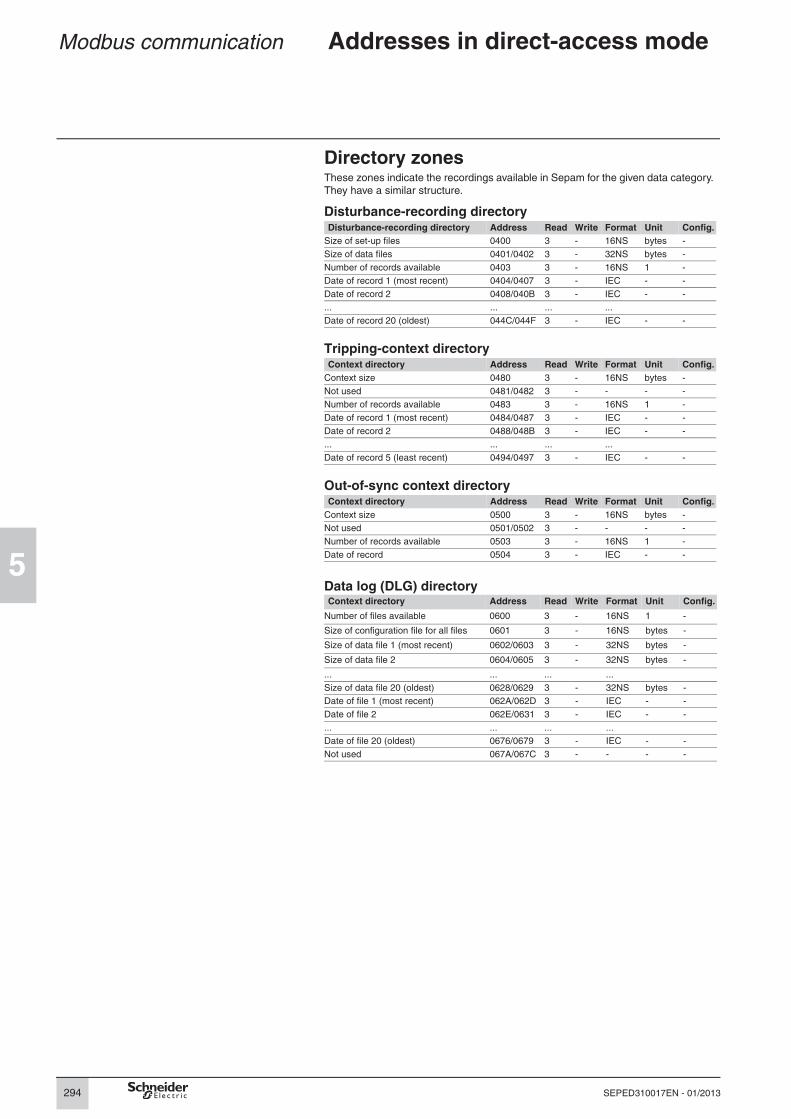
Directory zonesThese zones indicate the recordings available in Sepam for the given data category.
They have a similar structure.
Disturbance-recording directoryDisturbance-recording directory Address Read Write Format Unit Config.
Size of set-up files 0400 3 - 16NS bytes -
Size of data files 0401/0402 3 - 32NS bytes -
Number of records available 0403 3 - 16NS 1 -
Date of record 1 (most recent) 0404/0407 3 - IEC - -
Date of record 2 0408/040B 3 - IEC - -
... ... ... ...
Date of record 20 (oldest) 044C/044F 3 - IEC - -
Tripping-context directoryContext directory Address Read Write Format Unit Config.
Context size 0480 3 - 16NS bytes -
Not used 0481/0482 3 - - - -
Number of records available 0483 3 - 16NS 1 -
Date of record 1 (most recent) 0484/0487 3 - IEC - -
Date of record 2 0488/048B 3 - IEC - -
... ... ... ...
Date of record 5 (least recent) 0494/0497 3 - IEC - -
Out-of-sync context directoryContext directory Address Read Write Format Unit Config.
Context size 0500 3 - 16NS bytes -
Not used 0501/0502 3 - - - -
Number of records available 0503 3 - 16NS 1 -
Date of record 0504 3 - IEC - -
Data log (DLG) directoryContext directory Address Read Write Format Unit Config.
Number of files available 0600 3 - 16NS 1 -
Size of configuration file for all files 0601 3 - 16NS bytes -
Size of data file 1 (most recent) 0602/0603 3 - 32NS bytes -
Size of data file 2 0604/0605 3 - 32NS bytes -
... ... ... ...
Size of data file 20 (oldest) 0628/0629 3 - 32NS bytes -
Date of file 1 (most recent) 062A/062D 3 - IEC - -
Date of file 2 062E/0631 3 - IEC - -
... ... ... ...
Date of file 20 (oldest) 0676/0679 3 - IEC - -
Not used 067A/067C 3 - - - -

295
5
SEPED310017EN - 01/2013
Modbus communication Addresses in direct-access mode
Directory zones (cont.)Motor start report (MSR) directoryContext directory Address Read Write Format Unit Config.
Number of files available 0680 3 - 16NS 1 -
Size of configuration file for all files 0681 3 - 16NS bytes -
Size of data file 1 (most recent) 0682/0683 3 - 32NS bytes -
Size of data file 2 0684/0685 3 - 32NS bytes -
... ... ... ... ... ... ...
Size of data file 20 (oldest) 06A8/06A9 3 - 32NS bytes -
Date of file 1 (most recent) 06AA/06AD 3 - IEC - -
Date of file 2 06AE/06B1 3 - IEC - -
... ... ... ... ... ...
Date of file 20 (oldest) 06F6/06F9 3 - IEC - -
Not used 06FA/06FC 3 - - - -
Motor start trend (MST) directoryContext directory Address Read Write Format Unit Config.
Number of files available 0700 3 - 16NS 1 -
Size of configuration file for all files 0701 3 - 16NS bytes -
Size of all files 0702/0703 3 - 32NS bytes -
Not used 0704/0729 3 - - - -
Date of file 1 (most recent) 072A/072D 3 - IEC - -
Date of file 2 072E/0731 3 - IEC - -
... ... ... ...
Date of file 20 (oldest) 0776/0779 3 - IEC - -
Not used 077A/077C 3 - - - -
Test zoneThe test zone is a 16-word zone that may be accessed via the communication link
by all functions, in both read and write modes, to facilitate communication testing at
the time of commissioning or to test the link.These words are set to zero when Sepam starts.
Test zone Address Bit addresses Read Write Config.
Test word 1 0C00 C000/C00F 1, 2, 3, 4 5, 6, 15, 16 -
Test word 2 0C01 C010/C01F 1, 2, 3, 4 5, 6, 15, 16 -
... ... ... ... ...
Test word 16 0C0F C0F0/C0FF 1, 2, 3, 4 5, 6, 15, 16 -
296
5
SEPED310017EN - 01/2013
Modbus communication Addresses in direct-access mode
Status-condition and control zones
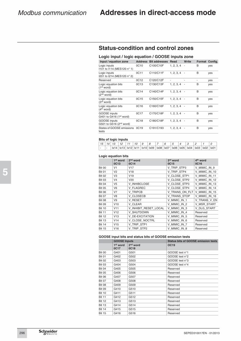
Logic input / logic equation / GOOSE inputs zoneInput / equation zone Address Bit addresses Read Write Format Config.
Logic inputs I101 to I114 (MES120 n° 1)
0C10 C100/C10F 1, 2, 3, 4 - B yes
Logic inputs I201 to I214 (MES120 n° 2)
0C11 C110/C11F 1, 2, 3, 4 - B yes
Reserved 0C12 C120/C12F - - - yes
Logic equation bits(1st word)
0C13 C130/C13F 1, 2, 3, 4 - B yes
Logic equation bits(2nd word)
0C14 C140/C14F 1, 2, 3, 4 - B yes
Logic equation bits(3rd word)
0C15 C150/C15F 1, 2, 3, 4 - B yes
Logic equation bits(4th word)
0C16 C160/C16F 1, 2, 3, 4 - B yes
GOOSE inputsG401 to G416 (1st word)
0C17 C170/C18F 1, 2, 3, 4 - B yes
GOOSE inputsG501 to G516 (2nd word)
0C18 C180/C18F 1, 2, 3, 4 - B yes
States of GOOSE emissions tests
0C19 C191/C193 1, 2, 3, 4 - B yes
Bits of logic inputs
15 14 13 12 11 10 9 8 7 6 5 4 3 2 1 0
- - Ix14 Ix13 Ix12 Ix11 Ix10 Ix09 Ix08 Ix07 Ix06 Ix05 Ix04 Ix03 Ix02 Ix01
Logic equation bits
1st word 0C13
2nd word0C14
3rd word0C15
4th word0C16
Bit 00 V1 V17 V_TRIP_STP3 V_MIMIC_IN_9
Bit 01 V2 V18 V_TRIP_STP4 V_MIMIC_IN_10
Bit 02 V3 V19 V_CLOSE_STP1 V_MIMIC_IN_11
Bit 03 V4 V20 V_CLOSE_STP2 V_MIMIC_IN_12
Bit 04 V5 V_INHIBCLOSE V_CLOSE_STP3 V_MIMIC_IN_13
Bit 05 V6 V_FLAGREC V_CLOSE_STP4 V_MIMIC_IN_14
Bit 06 V7 V_TRIPCB V_TRANS_ON_FLT V_MIMIC_IN_15
Bit 07 V8 V_CLOSECB V_TRANS_STOP V_MIMIC_IN_16
Bit 08 V9 V_RESET V_MIMIC_IN_1 V_TRANS_V_EN
Bit 09 V10 V_CLEAR V_MIMIC_IN_2 V_MSR_START
Bit 10 V11 V_INHIBIT_RESET_LOCAL V_MIMIC_IN_3 V_DLG_START
Bit 11 V12 V_SHUTDOWN V_MIMIC_IN_4 Reserved
Bit 12 V13 V_DE-EXCITATION V_MIMIC_IN_5 Reserved
Bit 13 V14 V_CLOSE_NOCTRL V_MIMIC_IN_6 Reserved
Bit 14 V15 V_TRIP_STP1 V_MIMIC_IN_7 Reserved
Bit 15 V16 V_TRIP_STP2 V_MIMIC_IN_8 Reserved
GOOSE input bits and status bits of GOOSE emission tests
GOOSE Inputs Status bits of GOOSE emission tests
1st word 0C17
2nd word0C18
OC19
Bit 00 G401 G501 GOOSE test n°1
Bit 01 G402 G502 GOOSE test n°2
Bit 02 G403 G503 GOOSE test n°3
Bit 03 G404 G504 GOOSE test n°4
Bit 04 G405 G505 Reserved
Bit 05 G406 G506 Reserved
Bit 06 G407 G507 Reserved
Bit 07 G408 G508 Reserved
Bit 08 G409 G509 Reserved
Bit 09 G410 G510 Reserved
Bit 10 G411 G511 Reserved
Bit 11 G412 G512 Reserved
Bit 12 G413 G513 Reserved
Bit 13 G414 G514 Reserved
Bit 14 G415 G515 Reserved
Bit 15 G416 G516 Reserved
297
5
SEPED310017EN - 01/2013
Modbus communication Addresses in direct-access mode
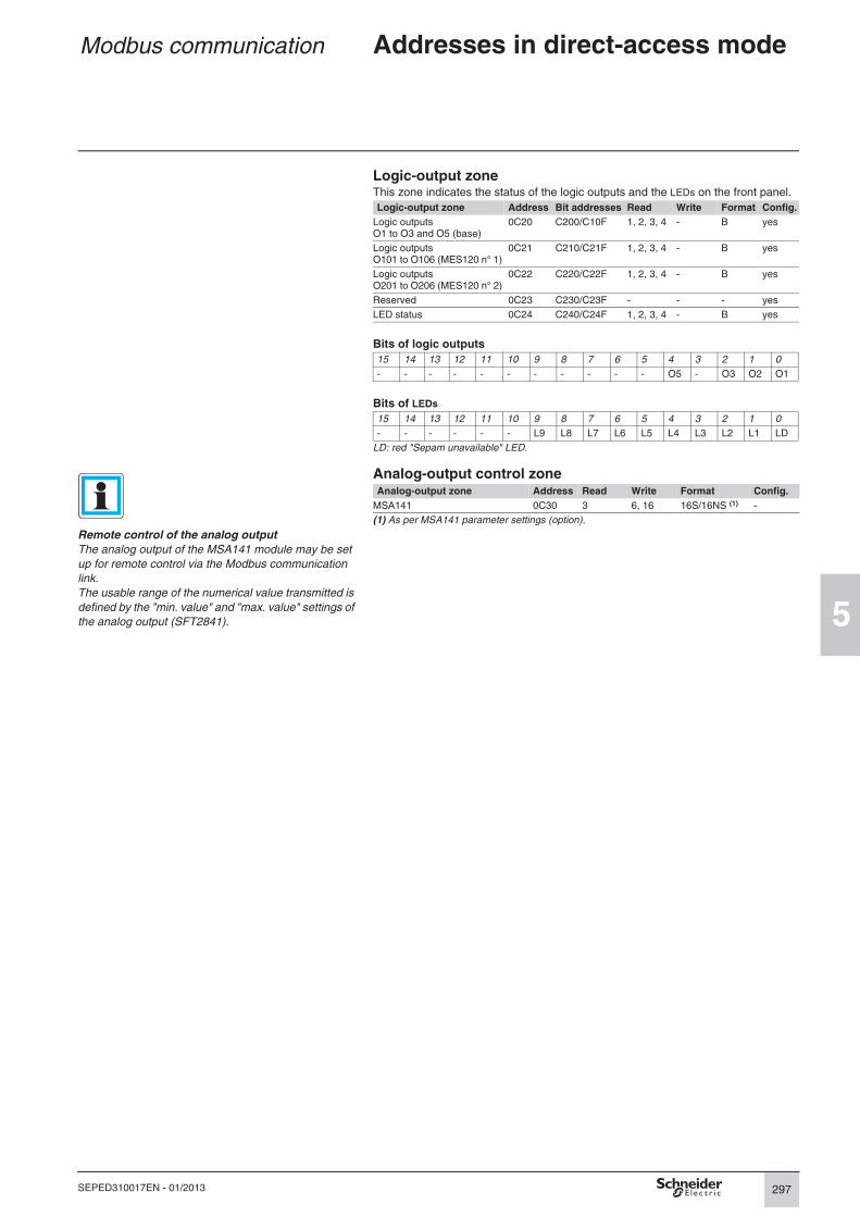
Logic-output zoneThis zone indicates the status of the logic outputs and the LEDs on the front panel.
Logic-output zone Address Bit addresses Read Write Format Config.
Logic outputs O1 to O3 and O5 (base)
0C20 C200/C10F 1, 2, 3, 4 - B yes
Logic outputs O101 to O106 (MES120 n° 1)
0C21 C210/C21F 1, 2, 3, 4 - B yes
Logic outputs O201 to O206 (MES120 n° 2)
0C22 C220/C22F 1, 2, 3, 4 - B yes
Reserved 0C23 C230/C23F - - - yes
LED status 0C24 C240/C24F 1, 2, 3, 4 - B yes
Bits of logic outputs
15 14 13 12 11 10 9 8 7 6 5 4 3 2 1 0
- - - - - - - - - - - O5 - O3 O2 O1
Bits of LEDs
15 14 13 12 11 10 9 8 7 6 5 4 3 2 1 0
- - - - - - L9 L8 L7 L6 L5 L4 L3 L2 L1 LD
LD: red "Sepam unavailable" LED.
Analog-output control zoneAnalog-output zone Address Read Write Format Config.
MSA141 0C30 3 6, 16 16S/16NS (1) -
(1) As per MSA141 parameter settings (option).
Remote control of the analog output
The analog output of the MSA141 module may be set
up for remote control via the Modbus communication
link.
The usable range of the numerical value transmitted is
defined by the "min. value" and "max. value" settings of
the analog output (SFT2841).

298
5
SEPED310017EN - 01/2013
Modbus communication Addresses in direct-access mode
Remote-control zoneRemote-control zone Address Bit addresses Read Write Format Config.
STC1 to STC16 0C84 C840/C84F 1, 2, 3, 4 5, 6, 15, 16 B -
STC17 to STC32 0C85 C850/C85F 1, 2, 3, 4 5, 6, 15, 16 B -
STC33 to STC48 0C86 C860/C86F 1, 2, 3, 4 5, 6, 15, 16 B -
STC49 to STC64 0C87 C870/C87F 1, 2, 3, 4 5, 6, 15, 16 B -
TC1 to TC16 0C88 C880/C88F 1, 2, 3, 4 5, 6, 15, 16 B -
TC17 to TC32 0C89 C890/C89F 1, 2, 3, 4 5, 6, 15, 16 B -
TC33 to TC48 0C8A C8A0/C8AF 1, 2, 3, 4 5, 6, 15, 16 B -
TC49 to TC64 0C8B C8B0/C8BF 1, 2, 3, 4 5, 6, 15, 16 B -
Use of remote-control orders64 bits of pulse-type remote-control orders (TC) are available on Sepam series 60.
According to the configuration chosen, the TC can be executed in either of the
following modes:
b direct mode
b confirmed SBO (Select Before Operate) mode
Remote-control orders in direct mode
The remote-control order is executed when it is written in the remote-control word.
The program logic resets it to zero after the remote-control order is acknowledged.
Remote-control orders (TC) in confirmed SBO modeRemote-control orders involve two steps:
b selection by the master of the order to be sent by writing the bit in the STC word
and checking of the selection by rereading the word
b execution of the order to be sent by writing the bit in the TC word.
The remote-control order is executed if the bit in the STC word and the bit in the
associated TC word are set. The program logic resets the STC and TC bits to zero
after the remote-control order is acknowledged.
Deselection of the STC bit takes place:
b if the master deselects it by writing in the STC word
b if the master selects (write bit) a bit other than the one already selected
b if the master sets a bit in the TC word which does not match the selection. In this
case, no remote-control order is executed.
b if the related order is not given within 30 seconds.
Inhibiting predefined remote-control ordersPredefined processing of remote-control orders may be inhibited, except for the
tripping remote-control order TC1 which may be activated at any time:
b by choosing Local or Test control mode via the key-switch on Sepam relays with
mimic-based UMIs
b by assigning a logic input to the "Inhibit remote control" function.
The parameter setting of the logic input may be done in two modes:
b inhibition if the input is set to 1
b inhibition if the input is set to 0 (negative input).
Security
It is possible to protect the remote-control zone against writing, see the section on
security.
The choice between direct mode or confirmed SBO
mode for remote control orders is made in the Sepam
General characteristics configuration screen. This is a
global parameter that applies to:
b COM1 Sepam communication port,
b Ethernet communication port.

299
5
SEPED310017EN - 01/2013
Modbus communication Addresses in direct-access mode
Remote-control zone (cont'd)Pulse-type remote-control orders are pre-assigned to protection, control and
metering functions.
The assignment of the remote-control orders is given in the tables below.
Depending on the applications and functions in operation, certain remote-control
orders may not be applicable and will produce no effect.
If the switchgear function is enabled (or running), the following remote-control orders
are acknowledged:
b device tripping and closing
b recloser enabling and disabling.
The corresponding value for Sepam 2000 is indicated. This value corresponds to the
address, not the role (roles are not static in Sepam 2000).
Word 0C88: TC1 to TC16 Sepam 2000
Bit 00: TC1 Trip / open KTC33
Bit 01: TC2 Closing KTC34
Bit 02: TC3 Sepam reset KTC35
Bit 03: TC4 Peak demand current reset KTC36
Bit 04: TC5 Peak demand power reset KTC37
Bit 05: TC6 Reserved KTC38
Bit 06: TC7 Reserved KTC39
Bit 07: TC8 Enable recloser KTC40
Bit 08: TC9 Disable recloser KTC41
Bit 09: TC10 Free KTC42
Bit 10: TC11 Free KTC43
Bit 11: TC12 Free KTC44
Bit 12: TC13 Free KTC45
Bit 13: TC14 Free KTC46
Bit 14: TC15 Free KTC47
Bit 15: TC16 Free KTC48
Word 0C89: TC17 to TC32 Sepam 2000
Bit 00: TC17 Reserved KTC49
Bit 01: TC18 Inhibit disturbance-recording triggering (OPG) KTC50
Bit 02: TC19 Confirm disturbance-recording triggering (OPG) KTC51
Bit 03: TC20 Manual disturbance-recording triggering (OPG) KTC52
Bit 04: TC21 Free KTC53
to
Bit 12: TC29 Free KTC61
Bit 13: TC30 Inhibit thermal protection KTC62
Bit 14: TC31 Confirm thermal protection KTC63
Bit 15: TC32 Reset undercurrent protection KTC64
Word 0C8A: TC33 to TC48 Sepam 2000
Bit 00: TC33 Switching to setting group A -
Bit 01: TC34 Switching to setting group B -
Bit 02: TC35 Priority group shutdown -
Bit 03: TC36 Cancel priority group shutdown
Bit 04: TC37 Enable synchro-check -
Bit 05: TC38 Disable synchro-check -
Bit 06: TC39 Enable voltage check -
Bit 07: TC40 Disable voltage check -
Bit 08: TC41 Reserved -
Bit 09: TC42 Reserved -
Bit 10: TC43 Reserved -
Bit 11: TC44 Reserved -
Bit 12: TC45 Reserved -
Bit 13: TC46 Reserved -
Bit 14: TC47 Reserved -
Bit 15: TC48 Reserved -
300
5
SEPED310017EN - 01/2013
Modbus communication Addresses in direct-access mode
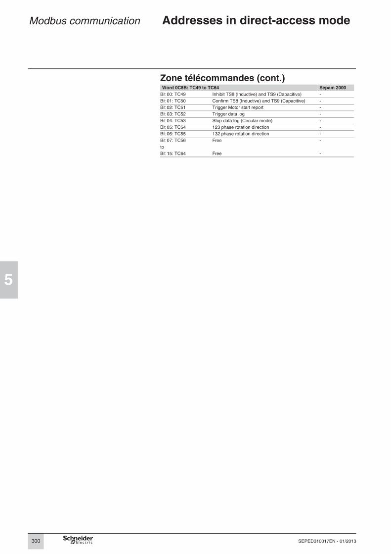
Zone télécommandes (cont.)Word 0C8B: TC49 to TC64 Sepam 2000
Bit 00: TC49 Inhibit TS8 (Inductive) and TS9 (Capacitive) -
Bit 01: TC50 Confirm TS8 (Inductive) and TS9 (Capacitive) -
Bit 02: TC51 Trigger Motor start report -
Bit 03: TC52 Trigger data log -
Bit 04: TC53 Stop data log (Circular mode) -
Bit 05: TC54 123 phase rotation direction -
Bit 06: TC55 132 phase rotation direction -
Bit 07: TC56 Free -
to
Bit 15: TC64 Free -

301
5
SEPED310017EN - 01/2013
Modbus communication Addresses in direct-access mode
Remote-indications zoneRemote-indications zone
Address Bit addresses Read Write Format Config.
Sepam check-word 0C8F C8F0/C8FF 1, 2, 3, 4 - B yes
TS1-TS16 0C90 C900/C90F 1, 2, 3, 4 - B yes
TS17-TS32 0C91 C910/C91F 1, 2, 3, 4 - B yes
TS33-TS48 0C92 C920/C92F 1, 2, 3, 4 - B yes
TS49-TS64 0C93 C930/C93F 1, 2, 3, 4 - B yes
TS65-TS80 0C94 C940/C94F 1, 2, 3, 4 - B yes
TS81-TS96 0C95 C950/C95F 1, 2, 3, 4 - B yes
TS97-TS112 0C96 C960/C96F 1, 2, 3, 4 - B yes
TS113-TS128 0C97 C970/C97F 1, 2, 3, 4 - B yes
TS129-TS144 0C98 C980/C98F 1, 2, 3, 4 - B yes
TS145-TS160 0C99 C990/C99F 1, 2, 3, 4 - B yes
TS161-TS176 0C9A C9A0/C9AF 1, 2, 3, 4 - B yes
TS177-TS192 0C9B C9B0/C9BF 1, 2, 3, 4 - B yes
TS193-TS208 0C9C C9C0/C9CF 1, 2, 3, 4 - B yes
TS209-TS224 0C9D C9D0/C9DF 1, 2, 3, 4 - B yes
TS225-TS240 0C9E C9E0/C9EF 1, 2, 3, 4 - B yes
The check work comprises a set of information on Sepam status.
The "high-speed reading" function (function 7) is used to access the most-significant
byte in the check word (bits 15 to 8).
Word 0C8F: Sepam check-word Notes
Bit 00 Reserved
Bit 01 Modbus Security function enabled (1)
Bit 02 Reserved
Bit 03 Sepam in “data loss” status in 2nd event zone (1) (2)
Bit 04 Event in 2nd event zone (1)
Bit 05 Setting group A in service (2)
Bit 06 Setting group B in service (2)
Bit 07 Sepam time not correct (2)
Bit 08 Sepam partial fault (2)
Bit 09 Sepam major fault
Bit 10 Sepam in parameter setting mode (2)
Bit 11 Remote setting inhibited
Bit 12 Inductive network (1)/capacitive (0)
Bit 13 Sepam not synchronous (2)
Bit 14 Sepam in “data loss” status in 1st event zone (1) (2)
Bit 15 Event in 1st event zone (1)
(1) This information is specific to each communication port.(2) Status changes of bits 3, 5, 6, 7, 8, 10, 13, 14 trigger sending of a time-tagged event (see the section on time-tagged events).
Remote-indication bits (TS) are pre-assigned to protection, control and metering functions.
The tables below present each remote-indication bit. Depending on the applications and
functions in operation, certain remote-indication bits may not be applicable.
The corresponding value for Sepam 2000 is indicated. This value corresponds to the
address, not the meaning (meanings are not static in Sepam 2000).
Word 0C90: TS1 to TS16 Sepam 2000
Bit 00: TS1 Matching fault or Trip Circuit Supervision KTS1
Bit 01: TS2 Control fault KTS2
Bit 02: TS3 TC / position discrepancy KTS3
Bit 03: TS4 External tripping 1 KTS4
Bit 04: TS5 Sepam not reset after fault KTS5
Bit 05: TS6 External tripping 2 KTS6
Bit 06: TS7 External tripping 3 KTS7
Bit 07: TS8 Cos ϕ inductive (1) KTS8
Bit 08: TS9 Cos ϕ capacitive (1) KTS9
Bit 09: TS10 Closed position KTS10
Bit 10: TS11 Device racked out KTS11
Bit 11: TS12 SF6 alarm KTS12
Bit 12: TS13 Earthing switch closed KTS13
Bit 13: TS14 Remote-control enabled KTS14
Bit 14: TS15 Overcurrent protection (summary) KTS15
Bit 15: TS16 Free KTS16
(1) TC49 can be used to inhibit this TS.
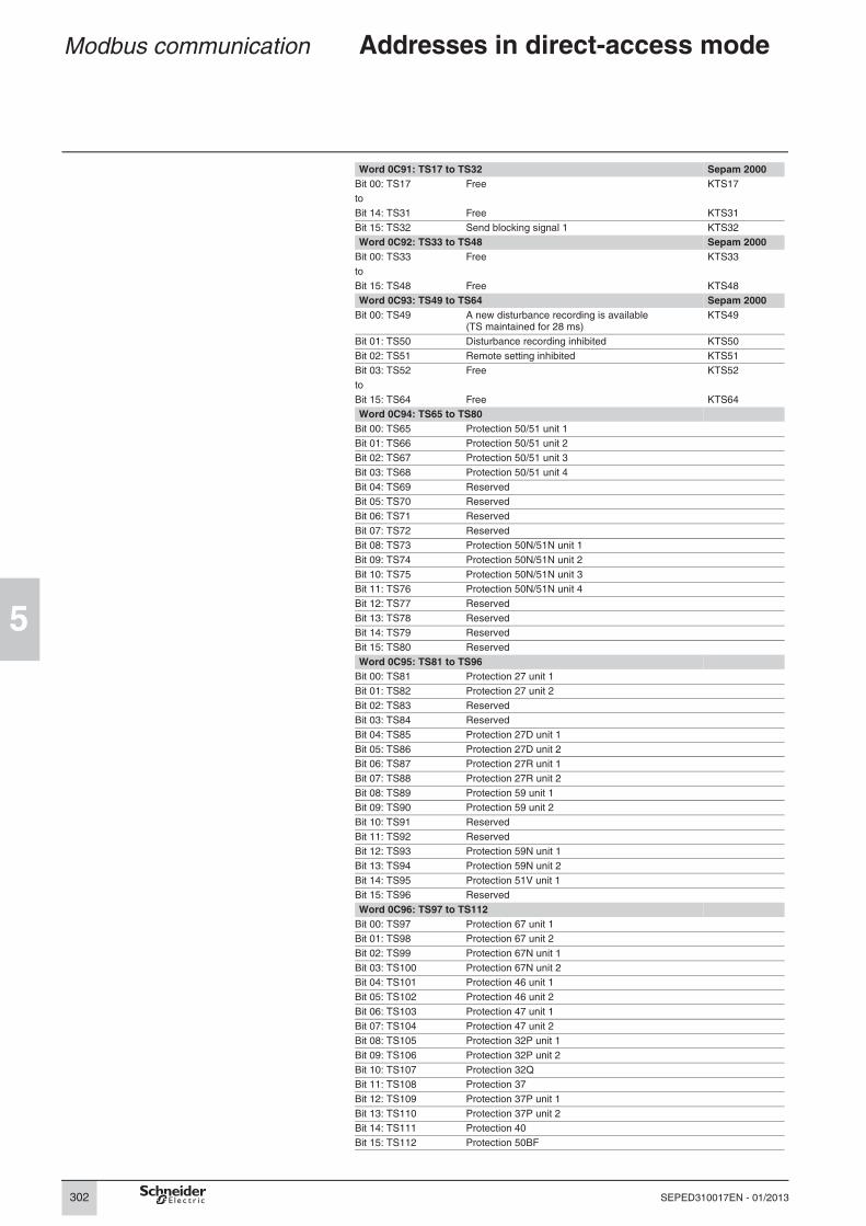
302
5
SEPED310017EN - 01/2013
Modbus communication Addresses in direct-access mode
Word 0C91: TS17 to TS32 Sepam 2000
Bit 00: TS17 Free KTS17
to
Bit 14: TS31 Free KTS31
Bit 15: TS32 Send blocking signal 1 KTS32
Word 0C92: TS33 to TS48 Sepam 2000
Bit 00: TS33 Free KTS33
to
Bit 15: TS48 Free KTS48
Word 0C93: TS49 to TS64 Sepam 2000
Bit 00: TS49 A new disturbance recording is available (TS maintained for 28 ms)
KTS49
Bit 01: TS50 Disturbance recording inhibited KTS50
Bit 02: TS51 Remote setting inhibited KTS51
Bit 03: TS52 Free KTS52
to
Bit 15: TS64 Free KTS64
Word 0C94: TS65 to TS80
Bit 00: TS65 Protection 50/51 unit 1
Bit 01: TS66 Protection 50/51 unit 2
Bit 02: TS67 Protection 50/51 unit 3
Bit 03: TS68 Protection 50/51 unit 4
Bit 04: TS69 Reserved
Bit 05: TS70 Reserved
Bit 06: TS71 Reserved
Bit 07: TS72 Reserved
Bit 08: TS73 Protection 50N/51N unit 1
Bit 09: TS74 Protection 50N/51N unit 2
Bit 10: TS75 Protection 50N/51N unit 3
Bit 11: TS76 Protection 50N/51N unit 4
Bit 12: TS77 Reserved
Bit 13: TS78 Reserved
Bit 14: TS79 Reserved
Bit 15: TS80 Reserved
Word 0C95: TS81 to TS96
Bit 00: TS81 Protection 27 unit 1
Bit 01: TS82 Protection 27 unit 2
Bit 02: TS83 Reserved
Bit 03: TS84 Reserved
Bit 04: TS85 Protection 27D unit 1
Bit 05: TS86 Protection 27D unit 2
Bit 06: TS87 Protection 27R unit 1
Bit 07: TS88 Protection 27R unit 2
Bit 08: TS89 Protection 59 unit 1
Bit 09: TS90 Protection 59 unit 2
Bit 10: TS91 Reserved
Bit 11: TS92 Reserved
Bit 12: TS93 Protection 59N unit 1
Bit 13: TS94 Protection 59N unit 2
Bit 14: TS95 Protection 51V unit 1
Bit 15: TS96 Reserved
Word 0C96: TS97 to TS112
Bit 00: TS97 Protection 67 unit 1
Bit 01: TS98 Protection 67 unit 2
Bit 02: TS99 Protection 67N unit 1
Bit 03: TS100 Protection 67N unit 2
Bit 04: TS101 Protection 46 unit 1
Bit 05: TS102 Protection 46 unit 2
Bit 06: TS103 Protection 47 unit 1
Bit 07: TS104 Protection 47 unit 2
Bit 08: TS105 Protection 32P unit 1
Bit 09: TS106 Protection 32P unit 2
Bit 10: TS107 Protection 32Q
Bit 11: TS108 Protection 37
Bit 12: TS109 Protection 37P unit 1
Bit 13: TS110 Protection 37P unit 2
Bit 14: TS111 Protection 40
Bit 15: TS112 Protection 50BF

303
5
SEPED310017EN - 01/2013
Modbus communication Addresses in direct-access mode
Word 0C97: TS113 to TS128
Bit 00: TS113 Protection 49RMS – alarm set point
Bit 01: TS114 Protection 49RMS – tripping set point
Bit 02: TS115 Protection 48/51LR (locked rotor)
Bit 03: TS116 Protection 48/51LR (locked rotor at start-up)
Bit 04: TS117 Protection 48/51LR (excessive starting time)
Bit 05: TS118 Protection 66
Bit 06: TS119 Protection 21B
Bit 07: TS120 Reserved
Bit 08: TS121 Reserved
Bit 09: TS122 Reserved
Bit 10: TS123 Reserved
Bit 11: TS124 Protection 64REF unit 1
Bit 12: TS125 Protection 64REF unit 2
Bit 13: TS126 Reserved
Bit 14: TS127 Reserved
Bit 15: TS128 An MSR is currently being recorded
Word 0C98: TS129 to TS144
Bit 00: TS129 Protection 81H unit 1
Bit 01: TS130 Protection 81H unit 2
Bit 02: TS131 Protection 81L unit 1
Bit 03: TS132 Protection 81L unit 2
Bit 04: TS133 Protection 81L unit 3
Bit 05: TS134 Protection 81L unit 4
Bit 06: TS135 Protection 81R unit 1
Bit 07: TS136 Protection 81R unit 2
Bit 08: TS137 Protection 12 unit 1
Bit 09: TS138 Protection 12 unit 2
Bit 10: TS139 Protection 14 unit 1
Bit 11: TS140 Protection 14 unit 2
Bit 12: TS141 Reserved
Bit 13: TS142 Reserved
Bit 14: TS143 A data log is in progress
Bit 15: TS144 A new Data log file is available (TS maintained for 28 ms)
Word 0C99: TS145 to TS160
Bit 00: TS145 Protection 38/49T alarm sensor 1 MET148 n° 1
Bit 01: TS146 Protection 38/49T tripping sensor 1 MET148 n° 1
Bit 02: TS147 Protection 38/49T alarm sensor 2 MET148 n° 1
Bit 03: TS148 Protection 38/49T tripping sensor 2 MET148 n° 1
Bit 04: TS149 Protection 38/49T alarm sensor 3 MET148 n° 1
Bit 05: TS150 Protection 38/49T tripping sensor 3 MET148 n° 1
Bit 06: TS151 Protection 38/49T alarm sensor 4 MET148 n° 1
Bit 07: TS152 Protection 38/49T tripping sensor 4 MET148 n° 1
Bit 08: TS153 Protection 38/49T alarm sensor 5 MET148 n° 1
Bit 09: TS154 Protection 38/49T tripping sensor 5 MET148 n° 1
Bit 10: TS155 Protection 38/49T alarm sensor 6 MET148 n° 1
Bit 11: TS156 Protection 38/49T tripping sensor 6 MET148 n° 1
Bit 12: TS157 Protection 38/49T alarm sensor 7 MET148 n° 1
Bit 13: TS158 Protection 38/49T tripping sensor 7 MET148 n° 1
Bit 14: TS159 Protection 38/49T alarm sensor 8 MET148 n° 1
Bit 15: TS160 Protection 38/49T tripping sensor 8 MET148 n° 1
Word 0C9A: TS161 to TS176
Bit 00: TS161 Protection 38/49T alarm sensor 1 MET148 n° 2
Bit 01: TS162 Protection 38/49T tripping sensor 1 MET148 n° 2
Bit 02: TS163 Protection 38/49T alarm sensor 2 MET148 n° 2
Bit 03: TS164 Protection 38/49T tripping sensor 2 MET148 n° 2
Bit 04: TS165 Protection 38/49T alarm sensor 3 MET148 n° 2
Bit 05: TS166 Protection 38/49T tripping sensor 3 MET148 n° 2
Bit 06: TS167 Protection 38/49T alarm sensor 4 MET148 n° 2
Bit 07: TS168 Protection 38/49T tripping sensor 4 MET148 n° 2
Bit 08: TS169 Protection 38/49T alarm sensor 5 MET148 n° 2
Bit 09: TS170 Protection 38/49T tripping sensor 5 MET148 n° 2
Bit 10: TS171 Protection 38/49T alarm sensor 6 MET148 n° 2
Bit 11: TS172 Protection 38/49T tripping sensor 6 MET148 n° 2
Bit 12: TS173 Protection 38/49T alarm sensor 7 MET148 n° 2
Bit 13: TS174 Protection 38/49T tripping sensor 7 MET148 n° 2
Bit 14: TS175 Protection 38/49T alarm sensor 8 MET148 n° 2
Bit 15: TS176 Protection 38/49T tripping sensor 8 MET148 n° 2

304
5
SEPED310017EN - 01/2013
Modbus communication Addresses in direct-access mode
Word 0C9B: TS177 to TS192
Bit 00: TS177 Reserved
Bit 01: TS178 Reserved
Bit 02: TS179 Reserved
Bit 03: TS180 Reserved
Bit 04: TS181 Reserved
Bit 05: TS182 Reserved
Bit 06: TS183 Reserved
Bit 07: TS184 Reserved
Bit 08: TS185 Thermistor alarm
Bit 09: TS186 Thermistor tripping
Bit 10: TS187 Buchholz alarm
Bit 11: TS188 Buchholz tripping
Bit 12: TS189 Thermostat alarm
Bit 13: TS190 Thermostat tripping
Bit 14: TS191 Pressure alarm
Bit 15: TS192 Pressure tripping
Word 0C9C: TS193 to TS208
Bit 00: TS193 MET148-1 module sensor fault
Bit 01: TS194 MET148-2 module sensor fault
Bit 02: TS195 Inhibit thermal protection tripping
Bit 03: TS196 Main-phase reverse rotation
Bit 04: TS197 Reserved
Bit 05: TS198 Send blocking signal 2
Bit 06: TS199 Recloser: On
Bit 07: TS200 Recloser: ready
Bit 08: TS201 Recloser: final trip
Bit 09: TS202 Recloser: reclosing successful
Bit 10: TS203 Recloser: cycle 1 in progress
Bit 11: TS204 Recloser: cycle 2 in progress
Bit 12: TS205 Recloser: cycle 3 in progress
Bit 13: TS206 Recloser: cycle 4 in progress
Bit 14: TS207 Recloser: closing by recloser
Bit 15: TS208 Test mode
Word 0C9D: TS209 to TS224
Bit 00: TS209 Phase CT fault
Bit 01: TS210 Phase VT fault
Bit 02: TS211 Residual VT fault
Bit 03: TS212 Reserved
Bit 04: TS213 Reserved
Bit 05: TS214 Reserved
Bit 06: TS215 Load shedding
Bit 07: TS216 Restart
Bit 08: TS217 Min. V_aux
Bit 09: TS218 Max. V_aux
Bit 10: TS219 Battery low or absent
Bit 11: TS220 Request for synchro-checked closing
Bit 12: TS221 dU synchronization failure
Bit 13: TS222 dPhi synchronization failure
Bit 14: TS223 dF synchronization failure
Bit 15: TS224 Synchronization stop
Word 0C9E: TS225 to TS240
Bit 00: TS225 Synchronization failure
Bit 01: TS226 Synchronization succesful
Bit 02: TS227 Reserved
Bit 03: TS228 Reserved
Bit 04: TS229 Reserved
Bit 05: TS230 Reserved
Bit 06: TS231 Reserved
Bit 07: TS232 Reserved
Bit 08: TS233 Tripping
Bit 09: TS234 Closing coil monitoring
Bit 10: TS235 Cumulative breaking current monitoring
Bit 11: TS236 Coupling closing order
Bit 12: TS237 Coupling synchronization failure
Bit 13: TS238 Tripping by automatic transfer (AT)
Bit 14: TS239 Discrepancy in the phase rotation direction
Bit 15: TS240 Ethernet communication fault

305
5
SEPED310017EN - 01/2013
Modbus communication Addresses in direct-access mode
Zones for Sepam 2000 compatibility
Disturb. rec. identification zoneThis zone exists exclusively for address and format compatibility with Sepam 2000.
When compatibility is not required, use the directory zone (address 400).
Disturb. rec. identification zone Address Read Write Format Unit Config.
Reserved D204 3 - - - -
Reserved D205 3 - - - -
Size of set-up files D206 3 - 16NS bytes -
If data files are larger than 64 Kbytes, the number of
records is forced to zero. Only the last two records are
provided.
Size of data files D207 3 - 16NS bytes -
Number of records available D208 3 - 16NS 1 -
Date of record 1 (most recent) D209/D20C 3 - IEC -
Date of record 2 D20D/D210 3 - IEC -
Configuration zoneThis zone exists exclusively for address and format compatibility with Sepam 2000.
It is static and does not depend on the real configuration of the Sepam series 60
relay.
Configuration zone Address Read Write Value Config.
Not used FC00 3 - 0 -
Sepam series 60 FC01 3 - 1300 h -
Not managed FC02 3 - 0 -
Not managed FC03 3 - 0 -

306
5
SEPED310017EN - 01/2013
Modbus communication Addresses in direct-access mode
Metering zone x 1Metering zone x 1 Address Read Write Format Unit Config.
Phase current I1 FA00 3, 4 - 16NS 0.1 A yes
Phase current I2 FA01 3, 4 - 16NS 0.1 A yes
Phase current I3 FA02 3, 4 - 16NS 0.1 A yes
Residual current
On Sepam 2000, measured and calculated residual
currents are exclusive, i.e. they have the same Modbus
address. On Sepam series 60, the two values may both
exist: the compatible address is used for the calculated
value and the new address is used for the measured
value.
Number of starts / Inhibit time
On Sepam 2000, these two values are exclusive and
use the same Modbus address. They are differentiated
by the sign. On Sepam series 60, the two values may
both exist, the compatible address is used for the
number of starts and the new address is used for the
inhibit time.
Peak demand current IM1 FA03 3, 4 - 16NS 0.1 A yes
Peak demand current IM2 FA04 3, 4 - 16NS 0.1 A yes
Peak demand current IM3 FA05 3, 4 - 16NS 0.1 A yes
Phase-to-phase voltage U21 FA06 3, 4 - 16NS 1 V yes
Phase-to-phase voltage U32 FA07 3, 4 - 16NS 1 V yes
Phase-to-phase voltage U13 FA08 3, 4 - 16NS 1 V yes
Frequency f FA09 3, 4 - 16NS 0.01 Hz yes
Active power P FA0A 3, 4 - 16O 1 kW yes
Reactive power Q FA0B 3, 4 - 16O 1 kvar yes
Power factor cos ϕ FA0C 3, 4 - 16O 0.01 yes
Peak demand active power PM FA0D 3, 4 - 16NS 1 kW yes
Peak demand reactive power QM FA0E 3, 4 - 16NS 1 kvar yes
Residual current I0Σ FA0F 3, 4 - 16NS 0.1 A yes
T1: temperature 1 MET n° 1 FA10 3, 4 - 16O 1°C yes
T2: temperature 2 MET n° 1 FA11 3, 4 - 16O 1°C yes
T3: temperature 3 MET n° 1 FA12 3, 4 - 16O 1°C yes
T4: temperature 4 MET n° 1 FA13 3, 4 - 16O 1°C yes
T5: temperature 5 MET n° 1 FA14 3, 4 - 16O 1°C yes
T6: temperature 6 MET n° 1 FA15 3, 4 - 16O 1°C yes
T7: temperature 7 MET n° 1 FA16 3, 4 - 16O 1°C yes
T8: temperature 8 MET n° 1 FA17 3, 4 - 16O 1°C yes
T9: temperature 1 MET n° 2 FA18 3, 4 - 16O 1°C yes
T10: temperature 2 MET n° 2 FA19 3, 4 - 16O 1°C yes
T11: temperature 3 MET n° 2 FA1A 3, 4 - 16O 1°C yes
T12: temperature 4 MET n° 2 FA1B 3, 4 - 16O 1°C yes
Thermal capacity used FA1C 3, 4 - 16NS % yes
Number of starts FA1D 3, 4 - 16NS 1 yes
Reserved FA1E 3, 4 - - - -
Reserved FA1F 3, 4 - - - -
Reserved FA20 3, 4 - - - -
Reserved FA21 3, 4 - - - -
Phase-to-neutral voltage V1 FA22 3, 4 - 16NS 1 V yes
Phase-to-neutral voltage V2 FA23 3, 4 - 16NS 1 V yes
Phase-to-neutral voltage V3 FA24 3, 4 - 16NS 1 V yes
Residual voltage V0 FA25 3, 4 - 16NS 1 V yes
Residual current I0 FA26 3, 4 - 16NS 0.1 A yes
Reserved FA27 3, 4 - - - -
Reserved FA28 3, 4 - - - -
Reserved FA29 3, 4 - - - -
Reserved FA2A 3, 4 - - - -
Reserved FA2B 3, 4 - - - -
Reserved FA2C 3, 4 - - - -
Reserved FA2D 3, 4 - - - -
Reserved FA2E 3, 4 - - - -
Inhibit time FA2F 3, 4 - 16NS 1 min. yes

307
5
SEPED310017EN - 01/2013
Modbus communication Addresses in direct-access mode
Metering zone x 10Metering zone x 10 Address Read Write Format Unit Config.
Phase current I1 FB00 3, 4 - 16NS 1 A yes
Phase current I2 FB01 3, 4 - 16NS 1 A yes
Phase current I3 FB02 3, 4 - 16NS 1 A yes
Residual current
On Sepam 2000, measured and calculated residual
currents are exclusive, i.e. they have the same Modbus
address. On Sepam series 60, the two values may both
exist: the compatible address is used for the calculated
value and the new address is used for the measured
value.
Peak demand current IM1 FB03 3, 4 - 16NS 1 A yes
Peak demand current IM2 FB04 3, 4 - 16NS 1 A yes
Peak demand current IM3 FB05 3, 4 - 16NS 1 A yes
Phase-to-phase voltage U21 FB06 3, 4 - 16NS 10 V yes
Phase-to-phase voltage U32 FB07 3, 4 - 16NS 10 V yes
Phase-to-phase voltage U13 FB08 3, 4 - 16NS 10 V yes
Frequency f FB09 3, 4 - 16NS 0.1 Hz yes
Active power P FB0A 3, 4 - 16O 10 kW yes
Reactive power Q FB0B 3, 4 - 16O 10 kvar yes
Power factor cos ϕ FB0C 3, 4 - 16O 0.01 yes
Peak demand active power PM FB0D 3, 4 - 16NS 10 kW yes
Peak demand reactive power QM FB0E 3, 4 - 16NS 10 kvar yes
Residual current I0Σ FB0F 3, 4 - 16NS 1 A yes
Last tripping current Itrip1 FB10 3, 4 - 16NS 10 A yes
Last tripping current Itrip2 FB11 3, 4 - 16NS 10 A yes
Last tripping current Itrip3 FB12 3, 4 - 16NS 10 A yes
Last tripping current Itrip0 FB13 3, 4 - 16NS 1 A yes
Reserved FB14 3, 4 - - - -
Reserved FB15 3, 4 - - - -
Reserved FB16 3, 4 - - - -
Phase-to-neutral voltage V1 FB17 3, 4 - 16NS 10 V yes
Phase-to-neutral voltage V2 FB18 3, 4 - 16NS 10 V yes
Phase-to-neutral voltage V3 FB19 3, 4 - 16NS 10 V yes
Reserved FB1A 3, 4 - - - -
Reserved FB1B 3, 4 - - - -
Reserved FB1C 3, 4 - - - -
Residual voltage V0 FB1D 3, 4 - 16NS 10 V yes
Reserved FB1E 3, 4 - - - -
Reserved FB1F 3, 4 - - -
Reserved FB20 3, 4 - - -
Reserved FB21 3, 4 - - -
Reserved FB22 3, 4 - - -
Residual current I0 FB23 3, 4 - 16NS 1 A yes
Reserved FB24 3, 4 - - - -
Compact zoneCompact zone Address Read Write Format Unit Config.
Phase current I1 (x 1) FB80 3, 4 - 16NS 0.1 A -
Phase-to-phase voltage U21 (x 1) FB81 3, 4 - 16NS 1 V -
Active power P (x 1) FB82 3, 4 - 16O 1 kW -
Reactive power Q (x 1) FB83 3, 4 - 16O 1 kvar -
Sepam check-word (copy) FB84 3, 4 - B - -
TS1-TS16 FB85 3, 4 - B - -
TS17-TS32 FB86 3, 4 - B - -
TS33-TS48 FB87 3, 4 - B - -
TS49-TS64 FB88 3, 4 - B - -
Logic inputs I101 to I114 FB89 3, 4 - B - -
Logic inputs I201 to I214 FB8A 3, 4 - B - -
Reserved FB8B 3, 4 - - - -
Reserved FB8C 3, 4 - - - -
Reserved FB8D 3, 4 - - - -
Reserved FB8E 3, 4 - - - -
Reserved FB8F 3, 4 - - - -

308
5
SEPED310017EN - 01/2013
Modbus communication Time-setting and synchronization
Presentation
PE
50
58
1
Sepam manages the date and time internally. If auxiliary power is lost, the date and
time function continues to operate, on the condition that a charged battery was
installed.
The Sepam internal time function is used in particular to date alarms and other
records.
Sepam time can be viewed:
b with SFT2841, "Sepam diagnosis" screen
b on the Sepam display
b by a Modbus read of the synchronization zone.
Sepam also supplies in the check-word the indication "Sepam time not correct" if it
is necessary to reset the time (often the case when the battery is low or absent). This
information can also be viewed with SFT2841, on the "Sepam diagnosis" screen.
Time settingWhen Sepam is energized, the time is automatically set using the clock powered by
the backup battery, if the battery is charged.
When necessary, it is possible to set the time on the Sepam using:
b SFT2841 ("Sepam diagnosis" screen)
b Sepam User Machine Interface
b Serial Modbus communication (COM1)
b Modbus/TCP or SNTP (Ethernet)
Modbus time is set by writing, in a single block, the new value for the date and time
in the synchronization zone (time frame).
SFT2841: date and time on the "Sepam diagnosis" screen.
Synchronization
DE
81
02
0
To ensure long-term time stability or to coordinate a number of devices, it is possible
to synchronize Sepam relays.
A number of synchronization sources are accepted:
b none (synchronization inhibited)
b a pulse to logic input I103
b Modbus communication on COM1
b Ethernet (Modbus or SNTP)
The source is selected using the SFT2841 software, on the "General characteristics"
screen.
Non-synchronous status is indicated in the check-word. This information can also be
viewed with SFT2841, on the "Sepam diagnosis" screen.
When Sepam is synchronized, time setting is authorized only by sources that are
compatible with the synchronization.
Time setting Synchronization source
None COM1 Ethernet I103
Local b
Via COM1 b b b
Via Ethernet b b b
Synchronization by the Modbus communication linkThe time frame is used for both time setting and synchronization of Sepam. In this
case, it must be regularly sent at brief intervals (between 10 and 60 seconds) to
maintain synchronous time.
It is generally broadcast (slave number = 0).
The Sepam internal clock is reset each time a new time frame is received.
Synchronization is maintained if the reset amplitude is less than 100 milliseconds.
With synchronization via the Modbus network, accuracy depends on the master and
its control over frame transmission time on the communication network. Sepam is
synchronized without delay at the end of the receipt of the frame.
Time changes are made by sending a frame to Sepam with the new date and time.
Sepam then switches to a transitional non-synchronous status.
In synchronous status, non-reception of a time frame for over 200 seconds results in
the loss of synchronization.Synchronization of the Sepam clock by the communication network.
Remote monitoringand control
Sepam series 20
Sepam series 40
Sepam series 60
Sepam series 80
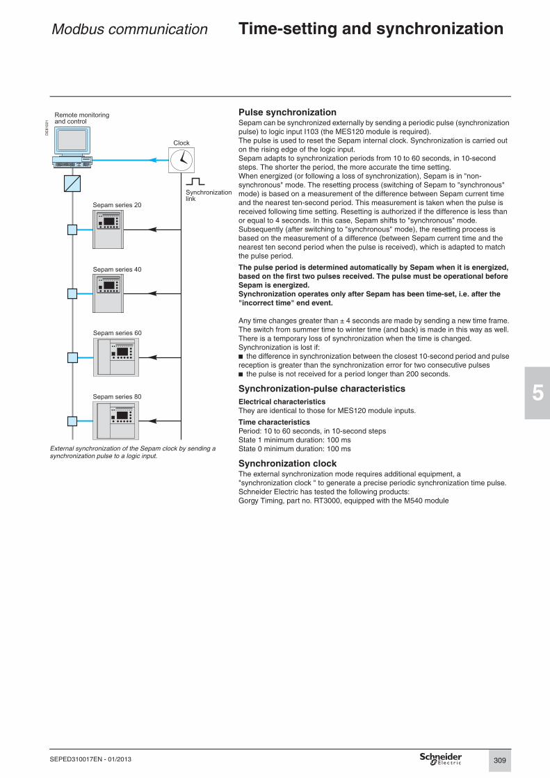
309
5
SEPED310017EN - 01/2013
Modbus communication Time-setting and synchronization
DE
81
02
1
Pulse synchronizationSepam can be synchronized externally by sending a periodic pulse (synchronization
pulse) to logic input I103 (the MES120 module is required).
The pulse is used to reset the Sepam internal clock. Synchronization is carried out
on the rising edge of the logic input.
Sepam adapts to synchronization periods from 10 to 60 seconds, in 10-second
steps. The shorter the period, the more accurate the time setting.
When energized (or following a loss of synchronization), Sepam is in "non-
synchronous" mode. The resetting process (switching of Sepam to "synchronous"
mode) is based on a measurement of the difference between Sepam current time
and the nearest ten-second period. This measurement is taken when the pulse is
received following time setting. Resetting is authorized if the difference is less than
or equal to 4 seconds. In this case, Sepam shifts to "synchronous" mode.
Subsequently (after switching to "synchronous" mode), the resetting process is
based on the measurement of a difference (between Sepam current time and the
nearest ten second period when the pulse is received), which is adapted to match
the pulse period.
The pulse period is determined automatically by Sepam when it is energized, based on the first two pulses received. The pulse must be operational before Sepam is energized.Synchronization operates only after Sepam has been time-set, i.e. after the "incorrect time" end event.
Any time changes greater than ± 4 seconds are made by sending a new time frame.
The switch from summer time to winter time (and back) is made in this way as well.
There is a temporary loss of synchronization when the time is changed.
Synchronization is lost if:
b the difference in synchronization between the closest 10-second period and pulse
reception is greater than the synchronization error for two consecutive pulses
b the pulse is not received for a period longer than 200 seconds.
Synchronization-pulse characteristics
Electrical characteristicsThey are identical to those for MES120 module inputs.
Time characteristicsPeriod: 10 to 60 seconds, in 10-second steps
State 1 minimum duration: 100 ms
State 0 minimum duration: 100 ms
Synchronization clockThe external synchronization mode requires additional equipment, a
"synchronization clock " to generate a precise periodic synchronization time pulse.
Schneider Electric has tested the following products:
Gorgy Timing, part no. RT3000, equipped with the M540 module
External synchronization of the Sepam clock by sending a synchronization pulse to a logic input.
Sepam series 20
Sepam series 40
Sepam series 60
Sepam series 80
Remote monitoringand control
Clock
Synchronizationlink

310
5
SEPED310017EN - 01/2013
Modbus communication Time-tagged events
PresentationThe time-tagging function assigns a date and precise time to status changes (events)
so that they can be accurately organized over time.
Time-tagging is systematic and concerns:
b logic inputs
b remote indications
b certain information pertaining to Sepam equipment (see Sepam check-word).
Events may be used by a remote monitoring and control system for data logging and
histories, for example.
The remote monitoring and control system provides a chronological display of the
time-tagged data.
Description
Time-taggingEvent time-tagging uses the Sepam internal clock. When an event is detected, it is
tagged with the current Sepam time.
Time-tagging accuracy depends essentially on how well the Sepam internal clock is
synchronized (see the section on time setting and synchronization).
Inhibition in Test modeTest mode may be used to temporarily stop the transmission of all time-tagged
events when remote operation of the installation is not to be disturbed by
maintenance operations carried out on the electrical equipment. This mode may be
accessed via mimic-based UMIs by turning the key-switch.
When Sepam enters Test mode, it:
b transmits remote-indication TS208 "Test mode" with a value of 1
b interrupts the transmission of all time-tagged events.
When Sepam leaves Test mode, it transmits remote-indication TS208 "Test mode"
with a value of 0.
Time-tagged events can be transmitted again. Status changes that take place in Test
mode are permanently lost.
Event queuesSepam has four internal storage queues (two per communication port) with a
capacity of 64 events. Each queue is independent.
If one queue is full (63 events already recorded), a "data loss" event is generated in
the 64th position and the queue no longer receives event data. The other queues are
not affected and continue to receive any new detected events.
When a queue in "data loss" status is completely emptied, a "data loss" end event is
generated and the queue then receives any detected events.
For each event queue of a Modbus port, the check-work contains certain information:
b presence of an event: indicates that there is at least one event that has not been
read in the corresponding queue
b data loss: indicates that the queue is in "data loss" status (full).
InitializationEach time Sepam is initialized (energized), events are generated in the following
order:
b "data loss"
b "not synchronous"
b end of "data loss".
The "time not correct" event may also appear if there is no battery.
The function is initialized with the current values of the remote indication and logic
input status without creating any events related to those data. After the initialization
phase, event detection is activated.

311
5
SEPED310017EN - 01/2013
Modbus communication Time-tagged events
Reading of eventsTwo Modbus tables are used to read the corresponding queues of events, in groups
of four maximum, using a specific protocol to make sure no events are lost, even if
communication problems occur.
Event tables Addr. table 1 Addr. table 2 Read Write Config.
Exchange word 0040 0070 3 6, 16 -
Event 1 0041/0048 0071/0078 3 - -
Event 2 0049/0050 0079/0080 3 - -
Reading must address only the exchange word, or the
entire table.
Event 3 0051/0058 0081/0088 3 - -
Event 4 0059/0060 0089/0090 3 - -
Exchange wordIt is used to check event reading. It consists of the elements below.
Bit 15 14 13 12 11 10 9 8 7 6 5 4 3 2 1 0
Exchange number 0…255 Event number 0…4
The exchange number is initialized to zero when Sepam is energized and is
incremented for each transfer of a new set of events. When it reaches its maximum
value (FFh), it automatically goes back to zero.
Sepam numbers the exchanges and the master acknowledges the numbering.
The event number indicates the number of significant events are truly present in the
table. The remainder of the table is less significant.
Event table acknowledgmentFollowing correct reception of the set of events, the master must acknowledge the
exchange by writing an exchange word with:
b "Exchange number" field: number of the last exchange carried out
b "Event number" field: set to zero.
The acknowledged events are then cleared from the Sepam queue. If there are other
events, they are made available in the table and the exchange number is
incremented.
As long as an exchange is not acknowledged, the table remains as is and it is
possible to read it again.
If acknowledgment is incorrect (incorrect value for the exchange word), it is not taken
into account and the table remains as is.
Clearing an event queueWriting a value "xxFFh" in the exchange word (any exchange number, event
number = FFh) reinitializes the corresponding event queue (all stored events not yet
transmitted are deleted).
Description of event codingAn event is coded in 8 words with the following structure:
Word Information Coding
1 Type of event 0800 h
2 Event address Bit address (see inputs, TS, check-word)
3 Reserved 0
4 Event direction 0: falling edge1: rising edge
5 to 8 Event time IEC
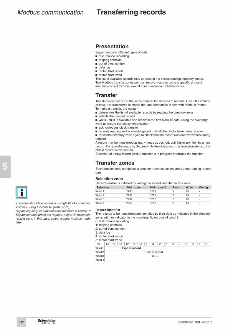
312
5
SEPED310017EN - 01/2013
Modbus communication Transferring records
PresentationSepam records different types of data:
b disturbance recording
b tripping contexts
b out-of-sync context
b data log
b motor start report
b motor start trend
The list of available records may be read in the corresponding directory zones.
Two Modbus transfer zones per port recover records using a specific protocol
ensuring correct transfer, even if communication problems occur.
TransferTransfer is carried out in the same manner for all types of records. Given the volume
of data, it is transferred in blocks that are compatible in size with Modbus frames.
To make a transfer, the master:
b determines the list of available records by reading the directory zone
b selects the desired record
b waits until it is available and recovers the first block of data, using the exchange
word to ensure correct synchronization
b acknowledges block transfer
b repeats reading and acknowledgment until all the blocks have been received
b reads the directory zone again to check that the record was not overwritten during
transfer.
A record may be transferred as many times as desired, until it is overwritten by a new
record. If a record is made by Sepam while the oldest record is being transferred, the
oldest record is overwritten.
Selection of a new record while a transfer is in progress interrupts the transfer.
Transfer zonesEach transfer zone comprises a zone for record selection and a zone reading record
data.
Selection zoneRecord transfer is initiated by writing the record identifier to this zone.
Selection Addr. zone 1 Addr. zone 2 Read Write Config.
Word 1 2200 D200 3 16 -
Word 2 2201 D201 3 16 -
Word 3 2202 D202 3 16 -
The zone should be written in a single block containing
4 words, using function 16 (write word).
Sepam capacity for simultaneous transfers is limited. If
Sepam cannot handle the request, a type 07 exception
reply is sent. In this case, a new request must be made
later.
Word 4 2203 D203 3 16 -
Record identifierThe records to be transferred are identified by their date as indicated in the directory
zone, with an indicator in the most-significant byte of word 1:
0: disturbance recording
1: tripping contexts
2: out-of-sync context.
3: data log
4: motor start report
5: motor start trend.
Bit 15 14 13 12 11 10 9 8 7 6 5 4 3 2 1 0
Word 1 Type of record
Word 2 Date of record
Word 3 (IEC)
Word 4

313
5
SEPED310017EN - 01/2013
Modbus communication Transferring records
Data read zoneRecord data are made available in this zone.
The record transfer is reset if more than 2 seconds
elapse between consecutive data read operations.
Data reading Addr. zone 1 Addr. zone 2 Read Write Config.
Exchange word 2300 D300 3 6, 16 -
Data word 1 2301 D301 3 - -
Data word 2 2302 D302 3 - -
... ... ... 3 - -
Data word 124 237C D37C 3 - -
Reading must always begin at the beginning of the zone (exchange word). The data
bytes not included in the significant information (see the section on the exchange
word) do not contain significant values.
Exchange wordIt is used to check data reading. It consists of the elements below.
Bit 15 14 13 12 11 10 9 8 7 6 5 4 3 2 1 0
Exchange number 0…255 Number of usable bytes 0…248
The exchange number is initialized to zero when Sepam is energized and is
incremented for each transfer of a new block of data. When it reaches its maximum
value (FFh), it automatically goes back to zero.
Sepam numbers the exchanges and the master acknowledges the numbering.
The number of bytes indicates the usable size of the data zone. It is initialized to zero
after an energizing operation and varies between 0 and 248 (F8h).
The exchange word may also have the following values:
b 0000h: no "read request" has yet been made. This is especially the case when
Sepam is energized. The other data words are not significant.
b FFFFh: the "read request" has been processed, but the results are not yet
available in the read zone. It is necessary to read again later.
b xxFEh: the transfer has been cancelled or the record number is not known.
Reading acknowledgmentFollowing correct reception of the block of data, the master must acknowledge
reading by writing an exchange word with:
b "Exchange number" field: number of the last exchange carried out
b "Number of bytes" field: set to zero.
If transfer of the record is not finished, the exchange word is reset to FFFFh while the
next block of data is prepared, otherwise the exchange word is not modified.
As long as a read has not been acknowledged, the zone remains as is and it is
possible to read it again.
If acknowledgment is incorrect (incorrect value for the exchange word), it is not taken
into account and the zone remains as is.
Note: It is not necessary to acknowledge tripping contexts or out-of-sync contexts which are contained in a single block.
Data coding
Disturbance recordingEach record comprises two files as defined by the COMTRADE standard:
b configuration file (.CFG)
b data file (.DAT) in binary mode.
Because the configuration and data files are transferred together, a block may
contain the end of the configuration file and the beginning of the data file of a record.
It is up to the remote monitoring and control system to reconstruct the files in
accordance with the transmitted number of usable bytes and the size of the files
indicated in the directory zone.

314
5
SEPED310017EN - 01/2013
Modbus communication Transferring records
Tripping contextsWord Information Format Unit
00 (exchange word)
01 to 04 Context date IEC -
05/06 Tripping current phase 1 Itrip1 32NS 0.1 A
07/08 Tripping current phase 2 Itrip2 32NS 0.1 A
09/0A Tripping current phase 3 Itrip3 32NS 0.1 A
0B/0C Residual current I0Σ 32NS 0.1 A
0D/0E Residual current I0 32NS 0.1 A
0F/10 Negative-sequence current Ii 32NS 0.1 A
11/12 Phase-to-phase voltage U21 32NS 1 V
13/14 Phase-to-phase voltage U32 32NS 1 V
15/16 Phase-to-phase voltage U13 32NS 1 V
17/18 Phase-to-neutral voltage V1 32NS 1 V
19/1A Phase-to-neutral voltage V2 32NS 1 V
1B/1C Phase-to-neutral voltage V3 32NS 1 V
1D/1E Residual voltage V0 32NS 1 V
1F/20 Positive sequence voltage Vd 32NS 1 V
21/22 Negative-sequence voltage Vi 32NS 1 V
23/24 Frequency f 32NS 0.01 Hz
25/26 Active power P 32S 1 kW
27/28 Reactive power Q 32S 1 kvar
29/2A Apparent power S 32S 1 kVA
2B/4A Reserved - -
4B/4C Neutral point voltage Vnt 32NS 1 V
4D/5C Reserved - -
5D/5E Phase rotation direction 32NS 0 = 1231 = 132
Out-of-sync contextWord Information Format Unit
00 (exchange word)
01 to 04 Context date IEC -
05/06 Voltage difference dU 32NS 0,1 % de Uns Sync1
07 Frequency difference df 16NS 0.001 Hz
08 Phase difference dϕ 16NS 0.1°

315
5
SEPED310017EN - 01/2013
Modbus communication Access to remote settings
PresentationAccess to Sepam settings via Modbus communication allows the user to remotely:
b read settings remotely (remote reading)
b modify settings remotely (remote setting), if it has been authorized.
Two Modbus zones per port offer access to the settings, using a specific protocol.
Accessible functionsRemote reading of settings concerns:
b all protection and similar functions
b the main Sepam general parameters.
Remote setting concerns exclusively the protection and similar functions.
Inhibiting remote settingIt is possible to inhibit the remote-setting function using a configuration parameter
accessible via SFT2841. In the default set-up (factory settings), the remote-setting
function is inhibited.
SecurityIt is possible to protect the remote-setting zone against writing, see the section on
security.
Operating principle
Remote setting readingFor remote setting reading, the master:
b selects the function whose settings are requested (write in the request zone)
b waits until it is available and recovers the setting values, using the exchange word
to ensure correct synchronization (read the setting read zone).
Remote settingFor remote setting, the master:
b selects the function whose settings are to be modified remotely and provides the
list of new settings (write in the remote-setting zone)
b waits until processing is finished and recovers the accepted setting values, using
the exchange word to ensure correct synchronization (read the setting read zone)
b checks that the settings have been accepted and processes any refusals.
It is necessary to make all the settings for the function concerned, even if some of
them have not changed.
Setting access zonesEach setting-access zone includes a zone to select the function whose settings are
requested, a zone to read the settings of the selected function and a zone to write
the settings.
Selection zone for setting requestsA setting read is initiated by writing the function identifier to this zone.
Inhibition of remote setting also concerns
the SFT2841 connected to Modbus
communication ports. When remote setting
is inhibited, only the SFT2841 locally connected to
Sepam can modify settings and parameters.
NOTICEHAZARD OF IMPROPER OPERATIONb The device must only be configured and set by
qualified personnel, using the results of the
installation protection system study.
b During commissioning of the installation and
after any modification, check that the Sepam
configuration and protection function settings are
consistent with the results of this study.
Failure to follow these instructions can result in equipment damage
Setting request Addr. zone 1 Addr. zone 2 Read Write Config.
Function identifier 2080 D080 3 6, 16 -
Function identificationEach function is identified by a function code, with a unit number (protection) or a
subcode (other functions). A list of the function codes is provided in the appendices,
no other values are valid.
Bit 15 14 13 12 11 10 9 8 7 6 5 4 3 2 1 0
Function code Unit number or subcode
Exception repliesIn addition to the usual cases, Sepam can send Modbus type 07 exception replies
(not acknowledged) if another remote reading (or remote setting) request is being
processed.

316
5
SEPED310017EN - 01/2013
Modbus communication Access to remote settings
Setting read zoneSetting values are made available in this zone.
Writing settings Addr. zone 1 Addr. zone 2 Read Write Config.
Function reference 2000 D000 3 - -
Setting 1 2001/2002 D001/D002 3 - -
Setting 2 2003/2004 D002/D003 3 - -
... ... ... 3 - -
Setting 62 207B/207C D07B/D07C 3 - -
Reading must always begin at the beginning of the zone (exchange word). The
length of the exchange may concern:
b the exchange word only (validity test)
b the maximum size of the zone (125 words)
b the usable size of the zone (determined by the function being addressed).
Exchange wordIt is used to check the reading of the settings and can have the following values:
b xxyy: where
v function code xx is not 00 or FFh
v unit number or subcode yy is not FFh.
The requested settings are available in the words below. The word is a copy of the
request. The zone contents remain valid until the next request is made.
b FFFFh: the request has been processed, but the results are not yet available. It is
necessary to read again later. The other words are not significant.
b xxFFh: where the function code xx is not 00 or FFh. The read request for the
settings of the designated function is not valid. The function (or the unit) does not
exist for this Sepam.
b 0000h: no "request frame" has yet been formulated. This is especially the case
when Sepam is energized. The other words are not significant.
SettingsAll settings are 32 bits in length (two Modbus words). They are specific to each
function and are described in the appendices.
Remote-setting zoneThe new setting values are written in this zone.
Read settings Addr. zone 1 Addr. zone 2 Read Write Config.
Function identifier 2100 D100 3 16 -
Setting 1 2101/2102 D101/D102 3 16 -
Setting 2 2103/2004 D102/D003 3 16 -
... ... ... 3 16 -
Setting 61 2179/217A D179/D17A 3 16 -
Writing must always begin at the beginning of the zone.
Function identifierIt is identical to that used to read the settings.
SettingsAll settings are 32 bits in length (two Modbus words). They are specific to each
function and are described in the appendices.
Exception replyIn addition to the usual cases, Sepam can send type 07 exception replies (not
acknowledged) if:
b another remote reading or setting request is being processed
b the remote setting function is inhibited
b Sepam is being set locally (SFT2841 or UMI).
Check on setting acceptanceAfter processing the remote-setting zone, Sepam updates the read zone with the
current function settings. In this case, the exchange word may also have another
value:
b FFFEh meaning that the settings have been refused. Certain values are incorrect
and are replaced by 7FFFFFFFh in the read zone.

317
5
SEPED310017EN - 01/2013
Modbus communication Customized table
PresentationTo reduce the number of Modbus exchanges required by the master to collect the
most frequently used information (and the bandwidth used on the network), a
customized table can be set up on each communication port of Sepam series 60.
This table is defined via Modbus, using a configuration table.
UseConfiguration tableConfiguration table Address Read Write Config.
Identifier 2680 3 16 -
Address datum 1 2681 3 16 -
Address datum 2 2682 3 16 -
... ... 3 16 -
Address datum 124 26FC 3 16 -
DE
50
74
2
Writing the configuration tableThis function is used to configure the data table. The first word in the configuration
table is used as the configuration identifier. It is copied as is in the first word of the
data table. The identifier can have any value, except 0. If the identifier is set to 0,
table configuration is cancelled.
The identifier enables masters to generate a number of typical configurations and to
check which is active. It is also the means to check that no other master has modified
the active configuration. This requires concerted management between the masters.
Each other word in the table contains the Modbus address of the datum that should
be set up in the corresponding spot in the data table (0 if the position is not used).
Only certain Modbus addresses can be set up in these tables. The valid addresses
are indicated in this document by "yes" in the "Config." column in the descriptions.
It is possible to write the table in part or in whole from any address. When 125 words
are used (the maximum size of the data table), at least two writings are required to
fill the configuration table because the maximum size of a Modbus write is 123 words.
Reading the configuration tableThis function is used to read and check the configuration of the data table. Each
address word can have one of the following values:
b 0000: position not used
b FFFFh: invalid address
b Address: address correctly configured.
It is possible to read the zone in part or in whole from any address.Example: by writing 0C8F to 268C, the result at 260C is a copy of the contents at address 0C8F (check-word).
Data tableData table Address Read Write Config.
Identifier 2600 3 - -
Datum 1 2601 3 - -
Datum 2 2602 3 - -
Caution: configuration takes place one Modbus word
after the other. For a 32-bit value, it is necessary to
provide the two successive addresses of the value.
(This characteristic may be used to switch the order of
words if there is a compatibility problem with the 32-bit
format. It is also possible to use only the least-
significant part of the 32-bit values if the range is
sufficient for the given application.)
... ... 3 - -
Datum 124 267C 3 - -
Reading the data tableThis function is used to read the data set up at the corresponding position.
The validity of the datum is indicated in the configuration table.
It is possible to read the table in part or in whole from any address.
Exception repliesSepam sends a Modbus type 07 exception reply (not acknowledged) if the data table
has not been set up. This may occur in the following cases:
b the table was never set up
b the table was set up, but one or more addresses are incorrect
The configuration table can be read again to identify the addresses in question;
b the configuration was cancelled (the identifier was set to 0)
b the configuration was lost (Sepam de-energized). In this case, it must be reloaded.

318
5
SEPED310017EN - 01/2013
Modbus communication Security
ExamplesSecure writing using function 16 (write word) of value
9999h to Modbus address ABCDh on slave 3.
Request frames
PresentationWith Sepam, it is possible to protect remote controls and remote settings using a
password.
Password protection of remote control and settings must be activated in the
SFT2841 software.
Two different passwords are required:
b one password for the remote controls
b one password for the remote settings
thus offering differentiated access.
The ON/OFF status of the security function is given by bit 01 of the Sepam check-
word.
ImplementationThe security function uses an extension of the Modbus protocol that encapsulates
the standard remote-control and remote-setting frames in a special frame.
Request framesThe request frame is made of the following components.
03 Slave Field Size (bytes)
66 Security function code Slave number 1
00 Version 102 (66h) 1 Security function code
0000 Reserved 00 1 Security version
1234 Password 0000 2 Reserved
10 Write-word function code xxxx 2 Password (BCD coding)
ABCD Address Standard function code 1
0001 Number of words to be written Standard frame data Encapsulated standard frame
02 Number of bytes ... n
9999 Value to be written CRC16 2
xxxx CRC16
The standard function codes that can be used in the request are the codes accepted
for writing to the corresponding addresses, i.e. 6 and 16 for words and 5 and 15 for
bits.
The security function does not affect reading.
The indicated password is the one created with SFT2841, for the given zone. It is a
16-bit BCD code (e.g. the entered password is 1234, the value in the Modbus field is
1234h).
Reply framesThe standard reply frame is also encapsulated, with a reduced header.
Normal reply frames03 Slave
66 Security function code
00 Version
10 Write-word function code
0001 Number of words written
xxxx CRC16
Exception framesWrite-word function exception: it is not possible to
write to the given address.
Field Size (bytes)
Slave number 1
102 (66h) 1 Security function code
00 1 Security version
03 Slave Standard function code 1
66 Security function code Standard reply Encapsulated standard reply
00 Version ... n
90 Write-word exception (10 + 80) CRC16 2
02 Incorrect address
xxxx CRC16 Exception replies
Security-function (access control) exceptionsWhen the security function is enabled on Sepam, request 102 must be used to
access Sepam's protected data.
If a non-secure request is used, a standard exception reply 02 (incorrect data
addresses) is sent to indicate that the requested data cannot be accessed.
When request 102 is used, a security-function exception reply 80 can be sent to
indicate access refused in the following two cases:
b Incorrect security level (the level asked for in the request is not 00)
b Incorrect password
Standard-function (encapsulated) exceptionsWhen access control has been negotiated successfully, the reply to request 102 can
encapsulate a standard exception reply, as described for replies associated with
Modbus standard function codes.
Security exception: incorrect password
03 Slave
E6 Security exception (66 + 80)
80 Access refused
xxxx CRC16

319
5
SEPED310017EN - 01/2013
Modbus communication Reading Sepam identification
PresentationThe "Read Device Identification" function provides standardized access to the
information required to clearly identify a device.
The description is made up of a set of objects (ASCII character strings).
Sepam series 60 accepts the "read identification" function (conformity level 02).
For a complete description of the function, refer to www.modbus.org. The
description below covers a subset of the function, adapted to Sepam series 60.
Implementation
Request frameThe request frame is made of the following components.
Field Size (bytes)
Slave number 1
43 (2Bh) 1 Generic access function code
14 (0Eh) 1 Read device identification
01 or 02 1 Type of read
00 1 Object number
CRC16 2
Sepam series 60 identificationThe objects making up the Sepam series 60
identification are listed below.
The type of read is used to select a simplified (01) or a standard (02) description.
Reply frameThe reply frame is made of the following components:
Number Type Value Field Size (bytes)
0: VendorName "Merlin Gerin" or "Schneider Electric"
Slave number 1
43 (2Bh) 1 Generic access function code
1: ProductCode Application EAN13 code 14 (0Eh) 1 Read device identification
2: MajorMinorRevision Application version number (Vx.yy)
01 or 02 1 Type of read
02 1 Conformity level
3: VendorURL "www.schneider-electric.com" 00 1 Continuation-frame flag (none for Sepam)
4: ProductName "Sepam series 60" 00 1 Reserved
5: ModelName Application name(e.g. "M61 Motor")
n 1 Number of objects (according to read type)
0bj1 1 Number of first object
6: UserAppName Sepam marking lg1 1 Length first object
The simplified description includes only objects 0 to 2. txt1 lg1 ASCII string of first object
..... ...
objn 1 Number nth object
lgn 1 Length nth object
txtn Ign ASCII string of nth object
CRC16 2
Exception frameIf an error occurs during request processing, a special exception frame is sent.
Field Size (bytes)
Slave number 1
171 (ABh) 1 Generic access exception (2Bh + 80h)
14 (0Eh) 1 Read device identification
01 1 Type of error
CRC16 2

320
5
SEPED310017EN - 01/2013
Modbus communication Appendix 1. Modbus protocol
IntroductionThis appendix describes the Modbus protocol and the functions required for Modbus
communication with Sepam. It is not intended to present the entire protocol.
Presentation
ExchangesThe Modbus protocol exchanges information using a request-reply mechanism
between a master and a slave.
An exchange is always initiated (request sent) by the master. The only action on
the part of a slave is to reply to requests received.
Where the communication network permits, several slaves units can be connected
to a single master. A request contains the slave address (a unique number) to identify
the recipient. Non-addressed slaves disregard the requests received.
Modbus Protocol Data UnitEvery Modbus request or response frame includes a Modbus PDU (protocol data unit) made up of 2 fields.
DE
81
02
2
Function code Data
Modbus is a master-slave network.
b function code (1 byte): indicates the type of request (1 to 127)
b data (0 to n bytes): depends on the function code, see below.
If there is no error, the function codes in the reply and in the request are identical.
Modbus data typesModbus uses 2 types of data: bits and 16-bit words (also called registers).
Each element of data is identified by a 16-bit address.
The most-significant byte in 16-bit words is always sent first, for both data and
addresses.
Serial line ModbusThis description is limited to the Modbus protocol using a serial link in binary mode
(RTU mode).
FramesAll the frames exchanged have the same structure, made up of 3 parts.
Slave address Modbus PDU Check (CRC16)
b Slave address (1 byte): from 1 to 247 (0 for broadcasting)
b Modbus PDU: as previously described
b Check (2 bytes): CRC16 used to check frame integrity.
The slave addresses in the reply and in the request are identical.
The maximum size of a frame is 256 bytes (255 for Sepam).
Synchronization of exchangesAny character that is received after a silence of more than 3.5 characters is
considered as the beginning of a new frame. A minimum silence of 3.5 characters
must always be observed between two frames.
A slave disregards all frames:
b received with a physical error for 1 or more characters (format error, parity error,
etc.)
b with an incorrect CRC16 result
b for which it is not the recipient.
BroadcastingThe master can also address all slaves using the conventional address 0. This type
of exchange is called broadcasting.
Slaves do not respond to broadcast messages. As a result, only messages that do
not require the transmission of data by the slaves can be broadcast.
DE
80
33
0
The broadcasting technique.
Sepam series 60
Master
Request
Reply
Slave Sepam series 80

321
5
SEPED310017EN - 01/2013
Modbus communication Appendix 1. Modbus protocol
Modbus over TCP/IPRequests and replies are exchanged as TCP/IP messages over a TCP connection.
The slave address is therefore its IP address.
FramesThe application layer part of a Modbus/TCP frame is made up of 2 fields:
MBAP Header Modbus PDU
b MBAP (Modbus Application) Header (7 bytes): identifies the frame
b Modbus PDU: as previously described.
Modbus Application headerIt contains the following fields:
Field Length Description Request Response
Transaction identifier
2 bytes Identification of a Modbus request/response transaction
Initialized by the client
Copied by the server from the received request
Protocol identifier 2 bytes 0 = Modbus protocol Initialized by the client
Copied by the server from the received request
Length 2 bytes Number of following bytes (including unit identifier)
Initialized by the client
Initialized by the server
Unit identifier 1 byte In case of gateways, identifies a remote slave device connected on a serial line. Should be 255 in other cases.
Initialized by the client
Copied by the server from the received request

322
5
SEPED310017EN - 01/2013
Modbus communication Appendix 1. Modbus protocol
Modbus protocol data units
Types of functionsThe Modbus protocol provides read and write functions as well as network-
management and diagnostics functions.
Read N bits functions (1 and 2)
Request
1 or 2 Address of first bit to be read Number of bits N to be read
1 byte 2 bytes 2 bytes
Reply
1 or 2 Number of bytes read Data
1 byte 1 byte (N + 7)/8 bytes
byte 1 byte 2 Function codeb 1 for internal or output bits
b 2 for input bits.
DataThe first bit sent is the LSB in the first byte and the subsequent bits follow in that
order. Any excess bits in the last byte are set to 0.
Read N words functions (3 and 4)
Request
7 6 5 4 3 2 1 0 7 6 5 4 3 2 1 0
1 1 1 1 1 1 1 1 0 0 0 1 1 1 1 1
1 1 0 0 0 0 0 0 2 1 1 1 1
B A 9 8 7 6 5 4 0 F E D C
Example: coding of the data field for reading 13 bits, starting at address 104h, with two reply bytes (the vertical numbers indicate the Modbus address of the bit in the corresponding position in the reply).
3 or 4 Address of first word to be read Number of words N to be read
1 byte 2 bytes 2 bytes
Reply
3 or 4 Number of bytes read Data
1 byte 1 byte 2N bytes
Function codeb 3 for internal or output words
b 4 for input words.
DataWords are sent in the order of increasing addresses.
Write bit function (5)Request
5 Bit address Bit value 0: bit set to 0FFh: bit set to 1
0
1 byte 2 bytes 1 byte 1 byte
ReplyIt is identical to the request.
Write word function (6)Request
6 Word address Word value
1 byte 2 bytes 2 bytes
Reply
It is identical to the request.
Write N consecutive bits function (15)
Request
0Fh Address of 1st bit Number of bits Number of bytes Data
1 byte 2 bytes 2 bytes 1 byte (N + 7)/8 bytes
DataBits are coded similar to the Read bits function.
Reply
0Fh Address of 1st bit written Number of bits written
1 byte 2 bytes 2 bytes

323
5
SEPED310017EN - 01/2013
Modbus communication Appendix 1. Modbus protocol
Write N consecutive words function (16)
Request
10h Address of 1st word Number of words Number of bytes Data
1 byte 2 bytes 2 bytes 1 byte 2N bytes
DataWords are sent in the order of increasing addresses.
Reply
10h Address of 1st word written Number of words written
1 byte 2 bytes 2 bytes
High-speed reading of 8 bits function (7)
Request
7
1 byte
Reply
7 Status byte
1 byte 1 byte
For Sepam, the status byte is the most-significant byte in the Sepam check-word
(address 0C8Fh), i.e. the bits C8F8h to C8FFh.
Diagnosis function (8)
Request
8 Subcode Data
1 byte 2 bytes 2 bytes
Reply
8 Subcode Data
1 byte 2 bytes 2 bytes
Subcodes for function 8
Sub-code
Use Request Reply
Datum Datum
0000h Echo mode Any Datum received
000Ah Reset counters CPT1 to CPT9 0000 0000
000Bh Read CPT1 (frames without errors) 0000 CPT1
000Ch Read CPT2 (frames with errors) 0000 CPT2
000Dh Read CPT3 (exception replies) 0000 CPT3
000Eh Read CPT4 (frames sent to station) 0000 CPT4
000Fh Read CPT5 (frames broadcast) 0000 CPT5
0010h Read CPT6 (not managed by Sepam) 0000 CPT6
0011h Read CPT7 (not managed by Sepam) 0000 CPT7
0012h Read CPT8 (frames with physical errors) 0000 CPT8
Read event counter function (11)For Sepam, the event counter is CPT9 (number of correct requests received and
correctly executed).
Request
0Bh
1 byte
Reply
0Bh 0000 Counter CPT9
1 byte 2 bytes 2 bytes
Exception repliesEach time a slave station receives a frame without errors that it cannot process, it
sends an exception reply with the elements below.
Request function code + 80h Type of exception
1 byte 1 byte
Type of exception Meaning
01 Unknown function code
02 Incorrect address
03 Incorrect datum
04 Device not ready
07 Negative acknowledgment
324
5
SEPED310017EN - 01/2013
Modbus communication Appendix 1. Modbus protocol
Calculation of the CRC16The CRC16 is calculated by the station sending the
frame. On reception, the CRC16 is recalculated and
compared to the received value. If the two values are
not the same, the frame is rejected.
The CRC16 uses two bytes. Contrary to the general
Modbus rule, the least-significant byte is sent first. It is
the product of the polynomial division of the frame by
the generating polynomial X16 + X15 + X2 + 1.
A number of methods may be used to calculate it. The
table method is often used because it is very effective.
The program below, written in the C language, is an
example of this method.
Example of calculation in the C languageThe function uses two parameters:
b unsigned char *puchMsg: points to the frame for CRC calculation
b unsigned short usDataLen: number of bytes in the frame.
The function returns the CRC as an unsigned short type. All possible CRC values
are listed in two tables indexed according to the value of the successive bytes in the
frame. One table contains the 256 possible values for the most-significant byte in the
CRC and the other table contains the 256 possible values for the least-significant
byte in the CRC.
Note: the result is ready to be inserted in the frame, the order of the bytes has already been reversed.
unsigned short CRC16(puchMsg, usDataLen)
unsigned char *puchMsg ; /* message to calculate CRC upon */
unsigned short usDataLen ; /* quantity of bytes in message */
unsigned char uchCRCHi = 0xFF ; /* high byte of CRC initialized */
unsigned char uchCRCLo = 0xFF ; /* low byte of CRC initialized */
unsigned uIndex ; /* will index into CRC lookup table */
while (usDataLen––) /* pass through message buffer */
uIndex = uchCRCHi ^ *puchMsgg++ ; /* calculate the CRC */
uchCRCHi = uchCRCLo ^ auchCRCHi[uIndex] ;
uchCRCLo = auchCRCLo[uIndex] ;
return (uchCRCHi << 8 | uchCRCLo) ;
/* Table of CRC values for high–order byte */
static unsigned char auchCRCHi[] =
0x00, 0xC1, 0x81, 0x40, 0x01, 0xC0, 0x80, 0x41, 0x01, 0xC0, 0x80, 0x41, 0x00, 0xC1, 0x81, 0x40,
0x01, 0xC0, 0x80, 0x41, 0x00, 0xC1, 0x81, 0x40, 0x00, 0xC1, 0x81, 0x40, 0x01, 0xC0, 0x80, 0x41,
0x01, 0xC0, 0x80, 0x41, 0x00, 0xC1, 0x81, 0x40, 0x00, 0xC1, 0x81, 0x40, 0x01, 0xC0, 0x80, 0x41,
0x00, 0xC1, 0x81, 0x40, 0x01, 0xC0, 0x80, 0x41, 0x01, 0xC0, 0x80, 0x41, 0x00, 0xC1, 0x81, 0x40,
0x01, 0xC0, 0x80, 0x41, 0x00, 0xC1, 0x81, 0x40, 0x00, 0xC1, 0x81, 0x40, 0x01, 0xC0, 0x80, 0x41,
0x00, 0xC1, 0x81, 0x40, 0x01, 0xC0, 0x80, 0x41, 0x01, 0xC0, 0x80, 0x41, 0x00, 0xC1, 0x81, 0x40,
0x00, 0xC1, 0x81, 0x40, 0x01, 0xC0, 0x80, 0x41, 0x01, 0xC0, 0x80, 0x41, 0x00, 0xC1, 0x81, 0x40,
0x01, 0xC0, 0x80, 0x41, 0x00, 0xC1, 0x81, 0x40, 0x00, 0xC1, 0x81, 0x40, 0x01, 0xC0, 0x80, 0x41,
0x01, 0xC0, 0x80, 0x41, 0x00, 0xC1, 0x81, 0x40, 0x00, 0xC1, 0x81, 0x40, 0x01, 0xC0, 0x80, 0x41,
0x00, 0xC1, 0x81, 0x40, 0x01, 0xC0, 0x80, 0x41, 0x01, 0xC0, 0x80, 0x41, 0x00, 0xC1, 0x81, 0x40,
0x00, 0xC1, 0x81, 0x40, 0x01, 0xC0, 0x80, 0x41, 0x01, 0xC0, 0x80, 0x41, 0x00, 0xC1, 0x81, 0x40,
0x01, 0xC0, 0x80, 0x41, 0x00, 0xC1, 0x81, 0x40, 0x00, 0xC1, 0x81, 0x40, 0x01, 0xC0, 0x80, 0x41,
0x00, 0xC1, 0x81, 0x40, 0x01, 0xC0, 0x80, 0x41, 0x01, 0xC0, 0x80, 0x41, 0x00, 0xC1, 0x81, 0x40,
0x01, 0xC0, 0x80, 0x41, 0x00, 0xC1, 0x81, 0x40, 0x00, 0xC1, 0x81, 0x40, 0x01, 0xC0, 0x80, 0x41,
0x01, 0xC0, 0x80, 0x41, 0x00, 0xC1, 0x81, 0x40, 0x00, 0xC1, 0x81, 0x40, 0x01, 0xC0, 0x80, 0x41,
0x00, 0xC1, 0x81, 0x40, 0x01, 0xC0, 0x80, 0x41, 0x01, 0xC0, 0x80, 0x41, 0x00, 0xC1, 0x81, 0x40 ;
/* Table of CRC values for low–order byte */
static char auchCRCLo[] =
0x00, 0xC0, 0xC1, 0x01, 0xC3, 0x03, 0x02, 0xC2, 0xC6, 0x06, 0x07, 0xC7, 0x05, 0xC5, 0xC4, 0x04,
0xCC, 0x0C, 0x0D, 0xCD, 0x0F, 0xCF, 0xCE, 0x0E, 0x0A, 0xCA, 0xCB, 0x0B, 0xC9, 0x09, 0x08, 0xC8,
0xD8, 0x18, 0x19, 0xD9, 0x1B, 0xDB, 0xDA, 0x1A, 0x1E, 0xDE, 0xDF, 0x1F, 0xDD, 0x1D, 0x1C, 0xDC,
0x14, 0xD4, 0xD5, 0x15, 0xD7, 0x17, 0x16, 0xD6, 0xD2, 0x12, 0x13, 0xD3, 0x11, 0xD1, 0xD0, 0x10,
0xF0, 0x30, 0x31, 0xF1, 0x33, 0xF3, 0xF2, 0x32, 0x36, 0xF6, 0xF7, 0x37, 0xF5, 0x35, 0x34, 0xF4,
0x3C, 0xFC, 0xFD, 0x3D, 0xFF, 0x3F, 0x3E, 0xFE, 0xFA, 0x3A, 0x3B, 0xFB, 0x39, 0xF9, 0xF8, 0x38,
0x28, 0xE8, 0xE9, 0x29, 0xEB, 0x2B, 0x2A, 0xEA, 0xEE, 0x2E, 0x2F, 0xEF, 0x2D, 0xED, 0xEC, 0x2C,
0xE4, 0x24, 0x25, 0xE5, 0x27, 0xE7, 0xE6, 0x26, 0x22, 0xE2, 0xE3, 0x23, 0xE1, 0x21, 0x20, 0xE0,
0xA0, 0x60, 0x61, 0xA1, 0x63, 0xA3, 0xA2, 0x62, 0x66, 0xA6, 0xA7, 0x67, 0xA5, 0x65, 0x64, 0xA4,
0x6C, 0xAC, 0xAD, 0x6D, 0xAF, 0x6F, 0x6E, 0xAE, 0xAA, 0x6A, 0x6B, 0xAB, 0x69, 0xA9, 0xA8, 0x68,
0x78, 0xB8, 0xB9, 0x79, 0xBB, 0x7B, 0x7A, 0xBA, 0xBE, 0x7E, 0x7F, 0xBF, 0x7D, 0xBD, 0xBC, 0x7C,
0xB4, 0x74, 0x75, 0xB5, 0x77, 0xB7, 0xB6, 0x76, 0x72, 0xB2, 0xB3, 0x73, 0xB1, 0x71, 0x70, 0xB0,
0x50, 0x90, 0x91, 0x51, 0x93, 0x53, 0x52, 0x92, 0x96, 0x56, 0x57, 0x97, 0x55, 0x95, 0x94, 0x54,
0x9C, 0x5C, 0x5D, 0x9D, 0x5F, 0x9F, 0x9E, 0x5E, 0x5A, 0x9A, 0x9B, 0x5B, 0x99, 0x59, 0x58, 0x98,
0x88, 0x48, 0x49, 0x89, 0x4B, 0x8B, 0x8A, 0x4A, 0x4E, 0x8E, 0x8F, 0x4F, 0x8D, 0x4D, 0x4C, 0x8C,
0x44, 0x84, 0x85, 0x45, 0x87, 0x47, 0x46, 0x86, 0x82, 0x42, 0x43, 0x83, 0x41, 0x81, 0x80, 0x40 ;

325
5
SEPED310017EN - 01/2013
Modbus communication Appendix 2. Function settings
Setting coding
Data formatAll the settings are transmitted in 32-bit signed 2's complement integer format.
Coding of tripping and timer hold curvesThe numbers correspond to the setting columns in the lists of settings.
Tripping curves0 = definite time
1 = inverse 9 = IEC very inverse / B
2 = long time inverse 10 = IEC extremely inverse / C
3 = very inverse 11 = IEEE moderately inverse
4 = extremely inverse 12 = IEEE very inverse
5 = ultra inverse 13 = IEEE extremely inverse
6 = RI 14 = IAC inverse
7 = IEC inverse / A 15 = IAC very inverse
8 = IEC long time inverse / B 16 = IAC extr. inverse
24 = Customized curve
25 = EPATR-B
26 = EPATR-C
Tripping curves
0 = definite time 11 = IEEE moderately inverse
7 = IEC inverse / A 12 = IEEE very inverse
8 = IEC long time inverse / B 13 = IEEE extremely inverse
9 = IEC very inverse / B 17 = Specific Schneider curve
10 = IEC extremely inverse / C 20 = RI²
Timer hold curves
0 = definite time
1 = IDMT
Common protection settingsAll protection functions have the following settings at the head of the table.
Setting Data Format/Unit
1 Latching 0: no1: yes
2 Program logic see below
3 Activity 0: Off1: On
4 Measurement origin see below
Details on program-logic field
Bit 31 30 .... 4 3 2 1 0
DES AGR CDC
CDC = 1: the protection function takes part in circuit-breaker/contactor control
= 0: the protection function does not take part
AGR = 1: the protection function takes part in genset shutdown
(generator application)
= 0: the protection function does not take part
DES = 1: the protection function takes part in de-excitation
(generator application)
= 0: the protection function does not take part
When a common protection setting is not applicable to a particular protection
function, it is signaled "reserved" in the table for the function.
Measurement originA few special cases of coding for the measurement-origin field, for the ANSI 50N/51
N, ANSI 67N/67NC and ANSI 59N protection functions, are indicated in the table
below:
Value 50N/51N 67N/67NC 59N
0 I0Σ I0Σ V0
1 I0 I0 Vnt
1
2
3

326
5
SEPED310017EN - 01/2013
Modbus communication Appendix 2. Function settings
Protection settingsThey are organized according to increasing ANSI codes.
ANSI 12 - OverspeedFunction number: 72xx
Unit 1: xx = 01, unit 2: xx = 02
Setting Data Format/Unit
1 to 3 Common settings
4 Reserved
5 Set point %
6 Tripping time delay 10 ms
ANSI 14 - UnderspeedFunction number: 77xx
Unit 1: xx = 01, unit 2: xx = 02
Setting Data Format/Unit
1 to 3 Common settings
4 Reserved
5 Set point %
6 Tripping time delay 10 ms
ANSI 21B - UnderimpedanceFunction number: 7401
Setting Data Format/Unit
1 to 3 Common settings
4 Reserved
5 Zs set point mΩ
6 Tripping time delay 10 ms
ANSI 25 – Synchro-checkFunction number: 1801
Setting Data Format/Unit
1 Reserved
2 Reserved
3 Activity 0: off1: on
4 dUs set point % Vnp sync1 or % Unp sync1
5 dFs set point 0.01 Hz
6 dPhis set point °
7 Us high set point % Vnp sync1 or % Unp sync1
8 Us low set point % Vnp sync1 or % Unp sync1
9 Operating modes(no-voltage conditions for which coupling is allowed)
1: Dead1 AND Live22: Live1 AND Dead23: Dead1 XOR Dead24: Dead1 OR Dead25: Dead1 AND Dead2
10 Lead time 10 ms
11 Use of voltage check for coupling authorization 0: no1: yes

327
5
SEPED310017EN - 01/2013
Modbus communication Appendix 2. Function settings
ANSI 27 - UndervoltageFunction number: 32xx
Unit 1: xx = 01 to unit 4: xx = 04
Setting Data Format/Unit
1 to 4 Common settings
5 Tripping curve 0: definite19: IDMT27: customized
6 Voltage mode 0: phase-to-neutral1: phase-to-phase
7 Us set point % Unp
8 Tripping time delay DT: 0.05 to 300 sIDMT: See note belowCustomized: range = 1 (TMS = 1)
9 DT of 1st point on the curve 10 ms
10 U/Un of 1st point on the curve %
11 DT of 2nd point on the curve 10 ms
12 U/Un of 2nd point on the curve %
13 DT of 3rd point on the curve N/A
14 U/Un of 3rd point on the curve N/A
...
29 DT of 11th point on the curve N/A
30 U/Un of of 11th point on the curve N/A
Note setting 8b For a setting mode with 10 I/IS: the range varies from 0.05 s to 300 s.
b For a setting in TMS (Time Multiplier Setting) mode, the range depends on the
selected curve and varies as follows:
v inverse (SIT) and IEC SIT/A: 0.04 to 4.20
v very inverse (VIT) and IEC VIT/B: 0.07 to 8.33
v long time inverse (LTI) and IEC LTI/B: 0.01 to 0.93
v extremely inverse (EIT) and IEC EIT/C: 0.13 to 15.47
v IEEE moderately inverse: 0.42 to 51.86
v IEEE very inverse: 0.73 to 90.57
v IEEE extremely inverse: 1.24 to 154.32
v IAC inverse: 0.34 to 42.08
v IAC very inverse: 0.61 to 75.75
v IAC extremely inverse: 1.08 to 134.4
Notes settings 9 to 30The customized curve is unique and only concerns unit 1. However, to retain
consistency with the Sepam software architecture, the same frame format is used for
all units. Unused points are set to (-1, -1). This is the case for the points for unit 2 and
above. It is also the case for additional points for unit 1. For example, if the curve is
defined by 6 points, the last 5 are set to (-1, -1). There is no "Number of points" setting
in the frame.
For each useful point, the value of T must be greater than or equal to that of the
previous point. The first point must be 0 (rising or falling operations are allowed).
The value of U/Un for the last useful point must be greater than all the other values
of U/Un.
ANSI 27D - Positive sequence undervoltageFunction number: 38xx
Unit 1: xx = 01, unit 2: xx = 02
Setting Data Format/Unit
1 to 4 Common settings
5 Vds set point % Unp
6 Tripping time delay 10 ms
ANSI 27R - Remanent undervoltageFunction number: 35xx
Unit 1: xx = 01, unit 2: xx = 02
Setting Data Format/Unit
1 to 4 Common settings
5 Us set point % Unp
6 Tripping time delay 10 ms

328
5
SEPED310017EN - 01/2013
Modbus communication Appendix 2. Function settings
ANSI 32P - Directional active overpowerFunction number: 53xx
Unit 1: xx = 01, unit 2: xx = 02
Setting Data Format/Unit
1 to 3 Common settings
4 Reserved
5 Access 0: reverse power1: overpower
6 Ps set point 100 W
7 Tripping time delay 10 ms
ANSI 32Q - Directional reactive overpowerFunction number: 5401
Setting Data Format/Unit
1 to 3 Common settings
4 Reserved
5 Access 0: reverse power1: overpower
6 Qs set point 100 var
7 Tripping time delay 10 ms
ANSI 37 - Phase undercurrentFunction number: 2201
Setting Data Format/Unit
1 to 3 Common settings
4 Reserved
5 Is set point % Ib
6 Tripping time delay 10 ms
ANSI 37P - Directional active underpowerFunction number: 55xx
Unit 1: xx = 01, unit 2: xx = 02
Setting Data Format/Unit
1 to 3 Common settings
4 Reserved
5 Access 0: drawn1: supplied
6 Ps set point 100 W
7 Tripping time delay 10 ms
ANSI 38/49T - Temperature monitoringFunction number: 46xx
Unit 1: xx = 01 to unit 16: xx = 10h
Setting Data Format/Unit
1 to 3 Common settings
4 Reserved
5 Ts1 alarm set point °C
6 Ts2 alarm set point °C
ANSI 40 - Field loss (underimpedance)Function number: 7001
Setting Data Format/Unit
1 to 3 Common settings
4 Reserved
5 Xa resistance 1 mΩ
6 Xb resistance 1 mΩ
7 Xc resistance 1 mΩ
8 Tripping time delay circle 1 10 ms
9 Tripping time delay circle Xd 10 ms

329
5
SEPED310017EN - 01/2013
Modbus communication Appendix 2. Function settings
ANSI 46 - Negative sequence / unbalanceFunction number: 45xx
Unit 1: xx = 01, unit 2: xx = 02
Setting Data Format/Unit
1 to 4 Common settings
5 Tripping curve
6 Is set point % Ib
7 Tripping time delay 10 ms
8 K setting 1 to 100
ANSI 47 - Negative sequence overvoltageFunction number: 40xx
Unit 1: xx = 01, unit 2: xx = 02
Setting Data Format/Unit
1 to 4 Common settings
5 Vis set point % Unp
6 Tripping time delay 10 ms
ANSI 48/51LR - Locked rotor / excessive starting timeFunction number: 4401
Setting Data Format/Unit
1 to 3 Common settings
4 Reserved
5 Is set point % Ib
6 ST excessive starting time 10 ms
7 LT locked rotor time 10 ms
8 LTS locked on start time 10 ms
ANSI 49RMS - Thermal overloadFunction number: 4301
Thermal overload
Setting Data Format/Unit
1 to 4 Common settings
5 Negative sequence factor (K) 0: none (0) 1: low (2.25)2: medium (4.5) 3: high (9)
6 Is set point (shift group 1/group 2) % Ib
7 Ambient temperature taken into account 0: no1: yes
8 Maximum equipment temperature °C
9 Additional settings taken into account (group 2) 0: no1: yes
10 Learnt cooling time constant (T2 learnt) taken into account
0: no1: yes
11 Group 1 - thermal alarm set point %
12 Group 1 - thermal tripping set point %
13 Group 1 - heating time constant
14 Group 1 - cooling time constant min.
15 Group 1 - initial heat rise %
16 Group 2 - thermal alarm set point %
17 Group 2 - thermal tripping set point %
18 Group 2 - heating time constant min.
19 Group 2 - cooling time constant min.
20 Group 2 - initial heat rise %
21 Group 2 - base current for group 2 0.1 A
22 49RMS cable - admissible current 0.1 A
49RMS capacitor - tripping current 0.1 A
23 Associated time constant min.
24 Current setting 0.1 A
25 Alarm current 0.1 A
26 Type of thermal model 0: generic
Note: b thermal overload for machines: parameters 1 to 21b thermal overload for cables: parameters 1 to 4 and 22 to 23b thermal overload for capacitors: parameters 1 to 4 and 22 to 25
2

330
5
SEPED310017EN - 01/2013
Modbus communication Appendix 2. Function settings
ANSI 49RMS - Thermal overload (cont.)Function number: 4301
Motor thermal overload
Setting Data Format/Unit
1 Latching 0: no, 1: yes
2 Circuit breaker control 0: no, 1: yes
3 Activity 0: off1: on
4 Ialarm = current alarm set point %
5 Itrip = current tripping set point %
6 Tlong = motor heating time constant min.
7 Tshort = stator heating time constant min.
8 Tcool = cooling time constant min.
9 Alpha = rotor/stator exchange coefficient %
10 IL = locked rotor current %
11 LRT = locked rotor torque %
12 Idem = starting current set point %
13 Ambient T taken into account by sensor 8 0: no, 1: yes
14 Tmax = max. stator temperature constant °C
15 Tc = locked rotor cold limit time seconds
16 Th = locked rotor hot limit time seconds
17 Sh = Heat rise set point for hot state bit %
... Reserved
25 Reserved
26 Type of thermal model (1) 1: Motor
(1) This setting is always at 1 for the motor thermal overload model.
Transformer thermal overload
Setting Data Format/Unit
1 Latching 0: no, 1: yes
2 Circuit breaker control 0: no, 1: yes
3 Activity 0: off1: on
4 Measurement origin 0: primary1: secondary
5 Type of transformer 0: AN dry-type1: AF dry-type2: distribution ONAN immersed3: High and medium power ONAN immersed4: ONAF5: OF6: OD
6 Insulation class (1) b Dry-type transformer: 105, 120, 130, 135, 180, 200 or 220°b Immersed transformer: 0 (not significant)Unit = °
7 Alarm temperature (group 1) (2) b Dry-type transformer:Class 105: 95 to 130°Class 120: 110 to 145°Class 130: 120 to 155°Class 180: 170 to 205°Class 200: 190 to 225°Class 220: 210 to 245°b Immersed transformer: 98 to 160 °Unit = °
8 Tripping temperature (group 1) Same as alarm temperature
9 Alarm temperature (group 2) (2) Same as group 1
10 Tripping temperature (group 2) Same as group 1
11 Transformer time constant 1 to 600 Unit = minutes
(1) This setting only applies to dry-type transformers. Value 0 accepted for an immersed transformer.(2) Alarm temperature must be less than the tripping temperature.(3) This parameter only applies to immersed transformers. Value 0 accepted for a dry-type transformer.(4) This setting is always at 1 for the transformer thermal overload model.
12 Oil time constant (3) 5 to 600 Unit = minutes
13 Ambient T taken into account by sensor 8 0: no, 1: yes
14 Oil T taken into account by sensor 8 (3) 0: no, 1: yes
15 Additional settings taken into account (group 2) (3)
0: no, 1: yes
16 Restricted oil flow 0: no, 1: yes
17 ... 25 Reserved
26 Type of thermal model (4) 2: Transformer

331
5
SEPED310017EN - 01/2013
Modbus communication Appendix 2. Function settings
ANSI 50BF - Breaker failureFunction number: 9801
Setting Data Format/Unit
1 Common settings
2 Reserved
3 Common settings
4 Reserved
5 Use of breaker closed input 0: no1: yes
6 Is set point 0.1 A
7 Time 10 ms
ANSI 50/51 - Phase overcurrentFunction number: 01xx
Unit 1: xx = 01 to unit 4: xx = 04
Setting Data Format/Unit
1 to 4 Common settings
5 Confirmation 0 = none1 = neg. seq. overvoltage2 = undervoltage
6 Group A - tripping curve
7 Group A - Is set point 0.1 A
8 Group A - tripping time delay 10 ms
9 Group A - timer hold curve
10 Group A - timer hold 10 ms
11 Group B - tripping curve
12 Group B - Is set point 0.1 A
13 Group B - tripping time delay 10 ms
14 Group B - timer hold curve
15 Group B - timer hold 10 ms
16 Group A - harmonic 2 restraint 0: active, 1: inactive
17 Group A - Isc min 0.1 A
18 Group B - harmonic 2 restraint 0: active, 1: inactive
19 Group B - Isc min 0.1 A
20 H2 restraint set point (1) %
(1) Parameter common to all groups and all units.
ANSI 50N/51N - Earth faultFunction number: 06xx
Unit 1: xx = 01 to unit 4: xx = 04
Setting Data Format/Unit
1 to 4 Common settings
5 Group A - tripping curve
6 Group A - Is0 set point 0.1 A
7 Group A - tripping time delay 10 ms
8 Group A - timer hold curve
9 Group A - timer hold 10 ms
10 Group A - H2 restraint 0: yes1: no
11 Group B - tripping curve
12 Group B - Is0 set point 0.1 A
13 Group B - tripping time delay 10 ms
14 Group B - timer hold curve
15 Group B - timer hold 10 ms
16 Group B - H2 restraint 0: yes1: no
ANSI 50V/51V - Voltage-restrained phase overcurrentFunction number: 1901
Setting Data Format/Unit
1 to 4 Common settings
5 Tripping curve
6 Is set point 0.1 A
7 Tripping time delay 10 ms
8 Timer hold curve
9 Timer hold 10 ms
1
3
1
3
1
3
1
3
1
3

332
5
SEPED310017EN - 01/2013
Modbus communication Appendix 2. Function settings
ANSI 59 - OvervoltageFunction number: 28xx
Unit 1: xx = 01, unit 2: xx = 02
Setting Data Format/Unit
1 to 4 Common settings
5 Voltage mode 0: phase-to-neutral1: phase-to-phase
6 Us set point % Unp
7 Tripping time delay 10 ms
8 Drop-out/pick-up ratio 0,05 %
ANSI 59N - Neutral voltage displacementFunction number: 39xx
Unit 1: xx = 01, unit 2: xx = 02
Setting Data Format/Unit
1 to 4 Common settings
5 Tripping curve 0: definite18: IDMT
6 Vs0 set point % Unp
7 Tripping time delay 10 ms
ANSI 64 REF - Restricted earth fault differentialFunction number: 64xx
Unit 1: xx = 01, unit 2: xx = 02
Setting Data Format/Unit
1 to 4 Common settings
5 Is0 set point 0.1 A
ANSI 66 - Starts per hourFunction number: 4201
Setting Data Format/Unit
1 Common settings
2 Reserved
3 Common settings
4 Reserved
5 Period of time Hours
6 Total number of starts 1
7 Number of consecutive hot starts 1
8 Number of consecutive cold starts 1
9 Delay between stop/start min.
10 Delay between consecutive starts min.
ANSI 67 - Directional phase overcurrentFunction number: 52xx
Unit 1: xx = 01, unit 2: xx = 02
Setting Data Format/Unit
1 to 3 Common settings
4 Reserved
5 Group A - direction 0: line 1: busbar
6 Group A - characteristic angle 3: 30° 4: 45° 5: 60°
7 Group A - tripping logic 0: 1/3 1: 2/3
8 Group A - tripping curve
9 Group A - Is set point 0.1 A
10 Group A - tripping time delay 10 ms
11 Group A - timer hold curve
12 Group A - timer hold 10 ms
13 Group B - direction 0: line 1: busbar
14 Group B - characteristic angle 3: 30° 4: 45° 5: 60°
15 Group B - tripping logic 0: 1/3 1: 2/3
16 Group B - tripping curve
17 Group B - Is set point 0.1 A
18 Group B - tripping time delay 10 ms
19 Group B - timer hold curve
20 Group B - timer hold 10 ms
1
3
1
3

333
5
SEPED310017EN - 01/2013
Modbus communication Appendix 2. Function settings
ANSI 67N/67NC - Directional earth faultFunction number: 50xx
Unit 1: xx = 01, unit 2: xx = 02
Setting Data Format/Unit
1 to 4 Common settings
5 Access 0: projection (type 1)1: directional (type 2)2: directional with adjustable sector (type 3)
6 Group A - direction 0: line 1: busbar
7 Group A - types 1 and 2: characteristic angle 0: -45° 1: 0° 2: 15°3: 30° 4: 45° 5: 60°6: 90°
Group A - type 3: limiting angle 1 0° to 359°
8 Group A - type 1: sector 2: sector 76° 3: sector 83°4: sector 86°
Group A - type 3: limiting angle 2 0° to 359°
9 Group A - tripping curve
10 Group A – Is0 set point 0.1 A
11 Group A - tripping time delay 10 ms
12 Group A - types 1 and 2: Vs0 set point % Unp
Group A - type 3: Vs0 set point 0.1% Unp
13 Group A - timer hold curve
14 Group A - timer hold 10 ms
15 Group A - memory time 10 ms
16 Group A - memory voltage % Unp
17 Group B - direction 0: line 1: busbar
18 Group B - types 1 and 2: characteristic angle Same as group A
Group B - type 3: limiting angle 1 0° to 359°
19 Group B - type 1: sector Same as group A
Group B - type 3: limiting angle 2 0° to 359°
20 Group B - tripping curve
21 Group B - Is0 set point 0.1 A
22 Group B - tripping time delay 10 ms
23 Group B - types 1 and 2: Vs0 set point % Unp
Group B - type 3: Vs0 set point 0.1% Unp
24 Group B - timer hold curve
25 Group B - timer hold 10 ms
26 Group B - memory time 10 ms
27 Group B - memory voltage % Unp
ANSI 81H - OverfrequencyFunction number: 57xx
Unit 1: xx = 01, unit 2: xx = 02
Setting Data Format/Unit
1 to 4 Common settings
5 Fs set point (1) 0.1 Hz
6 Tripping time delay 10 ms
7 Reserved
8 Vs set point % Unp
9 Fs set point 0.01 Hz(1) Setting 5 is reserved for future compatibility with firmware versions higher than version 8xx.
ANSI 81L - UnderfrequencyFunction number: 56xx
Unit 1: xx = 01 to unit 4: xx = 04
Setting Data Format/Unit
1 to 4 Common settings
5 Fs set point(1) 0.1 Hz
6 Tripping time delay 10 ms
7 Restraint 0: no1: yes
8 Vs set point % Unp
9 Inhibition set point for frequency variation Hz/s
10 Fs set point 0.01 Hz(1) Setting 5 is reserved for future compatibility with firmware versions higher than version 8xx.
1
3
1
3

334
5
SEPED310017EN - 01/2013
Modbus communication Appendix 2. Function settings
ANSI 81R – Rate of change of frequencyFunction number: 58xx
Unit: 1 xx = 01, unit 2: xx = 02
Setting Data Format/Unit
1 Latching 0: no1: yes
2 Switchgear control 0: no1: yes
3 Activity 0: off1: on
4 Reserved
5 dfs/dt set point 0.01 Hz/s
6 Tripping time delay 10 ms
Other function settings
ANSI 60 - CT supervisionFunction number: 2601
Setting Data Format/Unit
1 Reserved
2 Reserved
3 Common settings
4 Reserved
5 Action on 21G, 46, 40, 51N, 32P, 37P, 32Q, and 64REF protections
0: none1: inhibition
6 Tripping time delay 10 ms
ANSI 60FL - VT supervisionFunction number: 2701
Setting Data Format/Unit
1 Reserved
2 Reserved
3 Common settings
4 Reserved
5 Use breaker-position or voltage-presence criterion 0: circuit breaker1: voltage
6 Check loss of 3 V/2 U 0: no1: yes
7 Test current 0: no1: yes
8 Use Vi, Ii criterion 0: no1: yes
9 Action on 21G, 27, 27D, 32P, 32Q, 37P, 40, 47, 51V, 59, 59N protections
0: none1: inhibition
10 Action on 67 protection 0: non directional1: inhibition
11 Action on 67N protection 0: non directional1: inhibition
12 Vi tripping set point %
13 Ii tripping set point %
14 3 V/ 2 U loss time 10 ms
15 Vi, Ii criterion time 10 ms

335
5
SEPED310017EN - 01/2013
Modbus communication Appendix 2. Function settings
ANSI 79 - RecloserFunction number: 1701
Setting Data Format/Unit
1 Reserved
2 Reserved
3 Common settings
4 Reserved
5 Number of cycles 1 to 4
6 Reclaim time 10 ms
7 Safety time until ready 10 ms
8 Maximum additional dead time 0: no1: yes
9 Maximum wait time 10 ms
10 Cycle 1 activation mode see below
11 Cycle 2, 3, 4 activation mode see below
12 Cycle 1 dead time 10 ms
13 Cycle 2 dead time 10 ms
14 Cycle 3 dead time 10 ms
15 Cycle 4 dead time 10 ms
Cycle activation modeThe activation mode of each cycle is coded as follows:
Bit Activation by (if bit set to 1) / Non activation by (if bit set to 0)
0 Instantaneous protection 50/51 unit 1
1 Delayed protection 50/51 unit 1
2 Instantaneous protection 50/51 unit 2
3 Delayed protection 50/51 unit 2
4 Instantaneous protection 50/51 unit 3
5 Delayed protection 50/51 unit 3
6 Instantaneous protection 50/51 unit 4
7 Delayed protection 50/51 unit 4
8 Instantaneous protection 50N/51N unit 1
9 Delayed protection 50N/51N unit 1
10 Instantaneous protection 50N/51N unit 2
11 Delayed protection 50N/51N unit 2
12 Instantaneous protection 50N/51N unit 3
13 Delayed protection 50N/51N unit 3
14 Instantaneous protection 50N/51N unit 4
15 Delayed protection 50N/51N unit 4
16 Instantaneous protection 67N unit 1
17 Delayed protection 67N unit 1
18 Instantaneous protection 67N unit 2
19 Delayed protection 67N unit 2
20 Instantaneous protection 67 unit 1
21 Delayed protection 67 unit 1
22 Instantaneous protection 67 unit 2
23 Delayed protection 67 unit 2
24 Instantaneous V_DECL logic equation

336
5
SEPED310017EN - 01/2013
Modbus communication Appendix 2. Function settings
General parametersThese settings are read accessible only.
Function number: D002
Setting Data Format/Unit
1 Working language 1: English 2: other
2 Rated frequency 50, 60 (Hz)
3 Active group of settings 1: group A 2: group B
3: selection by logic input
4: selection by remote control
4 Demand-value integration period 5, 10, 15, 30, 60 minutes
5 Type of cubicle 1: incomer 2: feeder
6 Active-energy increment 100 to 5000000 (W)
7 Reactive-energy increment 100 to 5000000 (var)
8 Phase-rotation direction 1: direction 123 2: direction 132
9 Temperature unit 1: °C 2: °F
10 Remote-setting authorization 1: no 2: yes
11 Time synchronization mode 1: COM1 port 3: input I103
5: none 6: Ethernet port
12 Remote-control mode 1: SBO mode 2: direct mode
13 Reserved
14 Reserved
15 Rated auxiliary voltage 24 to 250 (V DC)
16 Aux. voltage alarm low set point % rated Vaux, min. 20 V
17 Aux. voltage alarm high set point % rated Vaux, max. 275 V
18 Logic inputs ignored on loss of Vaux 1: inactive 2: active
19 Base current Ib 0.2 to 1.3 In (A)
20 Rated current In 1 to 6250 A
21 Number of phase CTs 1: 2 CTs 2: 3 CTs
22 Phase CT rating 1: 1 A 2: 5 A 3: LPCT
23 Rated residual current In0 10 to 62500 (0.1 A)
24 Residual current measurement mode 1: CSH 2 A 3: CSH 20 A
4: 1 A CT 6: 5 A CT
8: ACE990 range 1
9: ACE990 range 2
11: not measured
25 Reserved
26 Rated primary voltage Unp 220 to 250000 (V)
27 Rated secondary voltage Uns 90 to 230 (V)
28 VT wiring 1: 3 V, 2: 2 U, 3: 1 U, 4: 1 V
29 Residual voltage mode 1: none 2: Σ3V
3: VT Uns/3 4: VT Uns/3
30 Neutral-point residual voltage measurement 1: none 2: present
31 Neutral-point rated voltage Unp 220 to 250000 (V)
32 Neutral-point rated voltage Uns 57 V to 133 V
33-48 Reserved
Application-specific parametersThese settings are read accessible only.
Function number: D003Setting Data Format/Unit
1 Transformer presence 1: no2: yes
2 Voltage winding 1 Un1 220 to 250000 V
3 Voltage winding 2 Un2 220 to 440000 V
4 Power S 100 to 999000 kVA
5 Vector shift 0 to 11
6 Rated motor speed 100 to 3000 rpm(1)
100 to 3600 rpm(2)
7 Number of pulses per rotation 1 to 1800
8 Zero speed threshold 5 to 20%
15 Rated power kW
16 Synchronous reactance of d axis 0,1 %
17 Transient reactance of d axis 0,1 %
18 Synchronous reactance of q axis 0,1 %
19 Moment of inertia for turbine + generator or motor + load
Kg.m2
(1) For a frequency of 50 Hz.(2) For a frequency of 60 Hz.