modbus plus and substation automation · modbus plus and substation automation schweitzer...
TRANSCRIPT
1
Modbus Plus andSubstation Automation
SCHWEITZER ENGINEERING LABORATORIES
SEL
OO
OSCHWEITZER ENGINEERING LABORATORIESPULLMAN WASHIMGTON USA
OO O
SEL-251 DISTRIBUTION RELAYFAULT TYPE
INST A B C Q N
FAULTTEST
RS LO
79 PHASE OVERCURRENT RELAY WITH VOLTAGE CONTROLNEGATIVE SEQUENCE OVERCURRENT RELAYGROUNDG OVERCURRENT RELAYMULTIPLE SHOT RECLOSING RELAYSELECTANLE SETTING GROUPSCIRCUIT BREAKER MONITORFAULT LOCATOR
138.4 kVolts
1 2 3
4 5 6
7 8 90
138.4 kVolts
1 2 3
4 5 6
7 8 90
1 3 8 .9
k Volts
A
B
C
bb Bitronics
1 3 8 . 61 3 8 . 7
91 3 8 .9
k Volts
A
B
C
bb Bitronics
1 3 8 . 61 3 8 . 7
9E
CNORMAFAIPICKURECLOSER
SYSTEM
TIMINSTANTANEOFREQUENCNEGATIVE
TARGET
STATU TARGET
ABCN
DP2000
NetworPartneV1.
E
CNORMAFAIPICKURECLOSER
SYSTEM
TIMINSTANTANEOFREQUENCNEGATIVE
TARGET
STATU TARGET
ABCN
DP2000
NetworPartneV1.
B853
Modicon
984MODEL 385
B881 B881 B801 B875 B885
Modicon Modicon Modicon Modicon Modicon Modicon
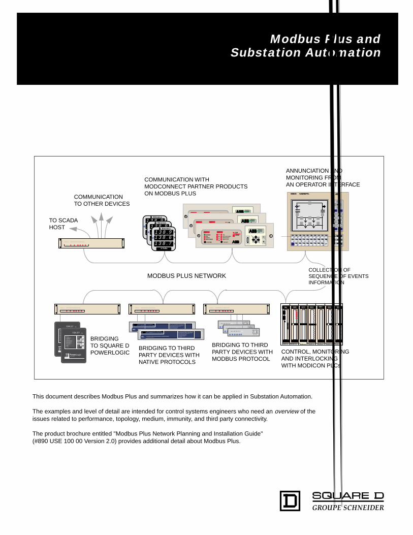
TO SCADAHOST
COMMUNICATIONTO OTHER DEVICES
COMMUNICATION WITHMODCONNECT PARTNER PRODUCTSON MODBUS PLUS
ANNUNCIATION ANDMONITORING FROMAN OPERATOR INTERFACE
BRIDGING TO THIRDPARTY DEVICES WITHNATIVE PROTOCOLS
BRIDGING TO THIRDPARTY DEVICES WITHMODBUS PROTOCOL
CONTROL, MONITORINGAND INTERLOCKINGWITH MODICON PLCs
MODBUS PLUS NETWORK
104.57
DSQUARE D
PowerLogicCIRCUIT MONITOR
AMMETER (A)VOLTMETER L L (V)VOLTMETER L N (V)WATTMETER (W)VARMETER (VA)VA METER (VA)POWER FACTOR METERFREQUENCY METER (Hz)DEMAND AMMETER (A)DEMAND POWER (W)DEMAND POWER (VA)WATT HOUR METERVARHOUR METERCURRENTVOLTAGEFACTORTOO SMALL
3 PHASEA((A B)B (B C)C (C A)N
SELECTMETER
METERSMINMAXALARM
KILOMEGA
V
V
PHASE
MODE
BRIDGINGTO SQUARE DPOWERLOGIC
COLLECTION OFSEQUENCE OF EVENTSINFORMATION
E
CNORMAFAIPICKURECLOSER
SYSTEM
TIMINSTANTANEOFREQUENCNEGATIVE
TARGET
STATU TARGET
ABCN
DP2000
NetworPartneV1.1 3 8 .
9
k Volts
A
B
C
bb Bitronics
1 3 8 . 61 3 8 . 7
9
138.4 kVolts
1 2 3
4 5 6
7 8 90
SCHWEITZER ENGINEERING LABORATORIES
SEL
OO
OSCHWEITZER ENGINEERING LABORATORIESPULLMAN WASHIMGTON USA
OO O
SEL-251 DISTRIBUTION RELAYFAULT TYPE
INST A B C Q N
FAULTTEST
RS LO
79 PHASE OVERCURRENT RELAY WITH VOLTAGE CONTROLNEGATIVE SEQUENCE OVERCURRENT RELAYGROUNDG OVERCURRENT RELAYMULTIPLE SHOT RECLOSING RELAYSELECTANLE SETTING GROUPSCIRCUIT BREAKER MONITORFAULT LOCATOR
Modicon NW BM85D002 BRIDGE MUX Modicon NW BM85D002 BRIDGE MUX Modicon NW BM85D002 BRIDGE MUX
Modicon NW BM85D002 BRIDGE MUX
This document describes Modbus Plus and summarizes how it can be applied in Substation Automation.
The examples and level of detail are intended for control systems engineers who need an overview of theissues related to performance, topology, medium, immunity, and third party connectivity.
The product brochure entitled "Modbus Plus Network Planning and Installation Guide"(#890 USE 100 00 Version 2.0) provides additional detail about Modbus Plus.

2
3
Introduction to Modbus Plus ................................................................................................................................. 4Terminology and Definitions .................................................................................................................................. 5Addressing and Token Rotation ............................................................................................................................ 6The “MSTR” Programming Block .......................................................................................................................... 7Available Network Topologies ................................................................................................................................ 8Bridging Between Two Modbus Plus Networks.................................................................................................... 9Twisted Pair and Fiber Optic Media ....................................................................................................................... 10Timing and Throughput .......................................................................................................................................... 11Network Diagnostics and Troubleshooting........................................................................................................... 12ModConnect Partners Program ............................................................................................................................. 13
Table of Contents
SCHWEITZER ENGINEERING LABORATORIES
SEL
OO
OSCHWEITZER ENGINEERING LABORATORIESPULLMAN WASHIMGTON USA
OO O
SEL-251 DISTRIBUTION RELAYFAULT TYPE
INST A B C Q N
FAULTTEST
RS LO
79 PHASE OVERCURRENT RELAY WITH VOLTAGE CONTROLNEGATIVE SEQUENCE OVERCURRENT RELAYGROUNDG OVERCURRENT RELAYMULTIPLE SHOT RECLOSING RELAYSELECTANLE SETTING GROUPSCIRCUIT BREAKER MONITORFAULT LOCATOR
1 3 8 .9
k Volts
A
B
C
bb Bitronics
1 3 8 . 61 3 8 . 7
91 3 8 .9
k Volts
A
B
C
bb Bitronics
1 3 8 . 61 3 8 . 7
9E
CNORMAFAIPICKURECLOSER
SYSTEM
TIMINSTANTANEOFREQUENCNEGATIVE
TARGET
STATU TARGET
ABCN
DP2000
NetworPartneV1.
E
CNORMAFAIPICKURECLOSER
SYSTEM
TIMINSTANTANEOFREQUENCNEGATIVE
TARGET
STATU TARGET
ABCN
DP2000
NetworPartneV1.
Modicon NW BM85D008 BRIDGE MUX
104.57
DSQUARE D
PowerLogicCIRCUIT MONITOR
AMMETER (A)VOLTMETER L L (V)VOLTMETER L N (V)WATTMETER (W)VARMETER (VA)VA METER (VA)POWER FACTOR METERFREQUENCY METER (Hz)DEMAND AMMETER (A)DEMAND POWER (W)DEMAND POWER (VA)WATT HOUR METERVARHOUR METERCURRENTVOLTAGEFACTORTOO SMALL
3 PHASEA((A B)B (B C)C (C A)N
SELECTMETER
METERSMINMAXALARM
KILOMEGA
V
V
PHASE
MODE
Modicon NW BM85D002 BRIDGE MUX
E
CNORMAFAIPICKURECLOSER
SYSTEM
TIMINSTANTANEOFREQUENCNEGATIVE
TARGET
STATU TARGET
ABCN
DP2000
NetworPartneV1.1 3 8 .
9
k Volts
A
B
C
bb Bitronics
1 3 8 . 61 3 8 . 7
9
SCHWEITZER ENGINEERING LABORATORIES
SEL
OO
OSCHWEITZER ENGINEERING LABORATORIESPULLMAN WASHIMGTON USA
OO O
SEL-251 DISTRIBUTION RELAYFAULT TYPE
INST A B C Q N
FAULTTEST
RS LO
79 PHASE OVERCURRENT RELAY WITH VOLTAGE CONTROLNEGATIVE SEQUENCE OVERCURRENT RELAYGROUNDG OVERCURRENT RELAYMULTIPLE SHOT RECLOSING RELAYSELECTANLE SETTING GROUPSCIRCUIT BREAKER MONITORFAULT LOCATOR
B
C
D
E F
A
A
H G
B853
Modicon
984MODEL 385
B881 B881 B801 B875 B885
Modicon Modicon Modicon Modicon Modicon Modicon
Modicon NW BM85D002 BRIDGE MUX
138.4 kVolts
1 2 3
4 5 6
7 8 90
138.4 kVolts
1 2 3
4 5 6
7 8 90
Modicon NW BM85D008 BRIDGE MUX
138.4 kVolts
1 2 3
4 5 6
7 8 90
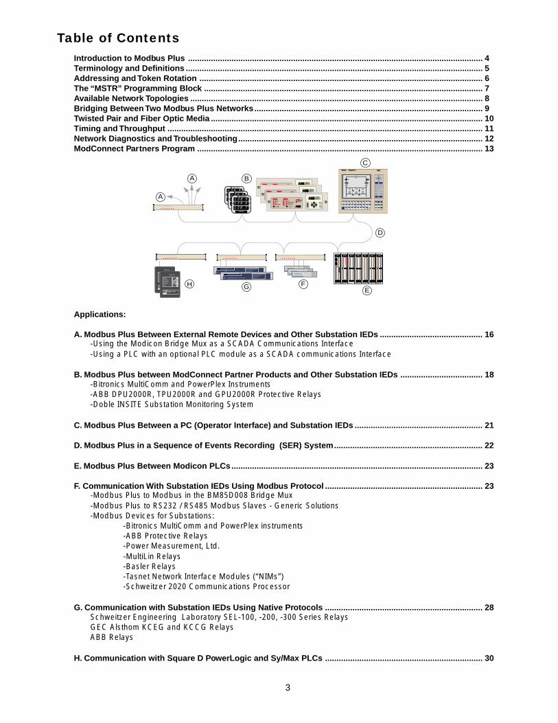
Applications:
A. Modbus Plus Between External Remote Devices and Other Substation IEDs ............................................. 16-Using the Modicon Bridge Mux as a SCADA Communications Interface-Using a PLC with an optional PLC module as a SCADA communications Interface
B. Modbus Plus between ModConnect Partner Products and Other Substation IEDs .................................... 18-Bitronics MultiComm and PowerPlex Instruments-ABB DPU2000R, TPU2000R and GPU2000R Protective Relays-Doble INSITE Substation Monitoring System
C. Modbus Plus Between a PC (Operator Interface) and Substation IEDs ........................................................ 21
D. Modbus Plus in a Sequence of Events Recording (SER) System................................................................. 22
E. Modbus Plus Between Modicon PLCs .............................................................................................................. 23
F. Communication With Substation IEDs Using Modbus Protocol ..................................................................... 23-Modbus Plus to Modbus in the BM85D008 Bridge Mux-Modbus Plus to RS232 / RS485 Modbus Slaves - Generic Solutions-Modbus Devices for Substations:
-Bitronics MultiComm and PowerPlex instruments-ABB Protective Relays-Power Measurement, Ltd.-MultiLin Relays-Basler Relays-Tasnet Network Interface Modules (“NIMs”)-Schweitzer 2020 Communications Processor
G. Communication with Substation IEDs Using Native Protocols ..................................................................... 28Schweitzer Engineering Laboratory SEL-100, -200, -300 Series RelaysGEC Alsthom KCEG and KCCG RelaysABB Relays
H. Communication with Square D PowerLogic and Sy/Max PLCs ..................................................................... 30

4
OverviewModbus Plus is a local area network system designed for industrial control and monitoring applications. The networkenables programmable controllers, host computers and other devices to communicate throughout plants andsubstations. Features of Modbus Plus include:
-Interlocking between PLCs (e.g. bus restoration)-Control and monitoring of protective relay I/O from PLCs-Sharing of analog data among IEDs-Acquisition of data by a network-resident host computer-Transfer of status and control between power plant and substation PLCs-Uploading and downloading of PLC programs-Download of configurations and settings to protective relays and other IEDs
Products With Modbus Plus-Modbus Plus cards for host computers (VME, ISA, Micro Channel)-Modicon Compact, “Slot-Mount”, and Quantum PLCs-ModConnect Partner products with the Modbus Plus chip set, such as relays and meters-Fiber optic Modems-Bridges to connect Modbus devices-Bridges to connect other non-Modbus serial devices-Bridges to connect two Modbus Plus networks
The Difference Between Modbus and Modbus PlusModbus is a messaging structure, widely used to establish master-slave communication between intelligent devices. A Modbus message sent from a master to a slave contains the address of the slave, the“command” (e.g. “read register” or “write register”), the data, and a check sum (LRC or CRC). Since Modbus is just a messaging structure, it can be sent out of any port (e.g. RS232, RS422, RS485) and over all media(e.g. fiber, radio, cellular, etc.).
Modbus Plus, on the other hand, is a complete protocol and network definition. Modbus Plus uses theModbus command structure, but carries the commands in a “token” that is rapidly passed from one device toanother. Modbus Plus defines exactly how the token is passed from one node to another, how retries areattempted, how data is checked for integrity, how errors are reported and how the communication port isdesigned. This highly specific definition of exactly how everything should be done is coded on to a chip setthat is installed in Modbus Plus devices. Modbus Plus also defines how the cable or fiber is connected andthe tools to be used. This controlled definition and implementation is what results in true “plug and play” innetworking systems.
-Peer-to-peer communication between network devices-Shielded twisted pair or fiber optic cable-Support of 64 addressable “nodes” per network (32 per cable run, two cable runs using repeater)-1500 feet on a single twisted pair network; up to 6,000 feet with repeaters-Dual cable and dual network topologies available-Data transfer rate of 1 million bits per second-Data throughput of 20,000 16-bit words per second-High noise immunity and high isolation (1.5kV cable to device)
Typical Applications of Modbus Plus in Substation Automation
Introduction to Modbus Plus

5
PC: Personal Computer; laptop, notebook, desktop or industrial (hardened)
PLC: Programmable Logic Controller or Programmable Controller
IED: Intelligent Electronic Device, such as a solid state protective relay or meter
Node: Any device that is physically connected to the Modbus Plus Cable. Modbus Plusnodes, such as PLCs, can send messages to other nodes or can be read from orwritten to by other nodes
Bridge: In communications systems, any device that converts or routes a protocol,language, data format or medium from one type to another. For Modbus Plusin substations, four types of 125VDC 19” rack mount bridges are offered:
-the configurable BM85D008 to convert from Modbus to Modbus Plus-the programmable BM85D002 to convert third party protocols to Modbus Plus-the BP85D002 for routing from one Modbus Plus network to another-the FR85D200 for converting from Modbus Plus twisted pair to fiber optic
Network: A grouping of nodes that are joined by some form of communication medium
Token: A grouping of bits that is passed in sequence from one node to another on asingle network. When the token is held by a node, access to the network isgranted for sending Modbus Plus messages
Peer-to-Peer: A communication protocol and network feature where individual nodes on thenetwork can initiate communication with any other nodes
Register: The memory address for a 16-bit word within a PLC
MSTR Block: A function block that can be placed in a ladder logic program to initiatecommunication with other nodes on Modbus Plus.
Read: An instruction to review the contents of a memory location. When a PLC “reads”register 40001 in another PLC, it is looking at the 16-bit word that is in thatmemory location.
Write: An instruction to change the contents of a memory location. When a PLC “writes”to register 40001 in another PLC, it is placing a 16-bit word into that memorylocation.
Global Data: A memory area in Modbus Plus devices reserved for sharing of information fromother Modbus Plus devices. 32 words (512 bits) from each of up to 63 devicesare held in this memory area. When a Modbus Plus device transfers data into thisGlobal Data area, it is broadcast to all other devices on Modbus Plus.
Peer Cop: A configuration option for Modicon PLCs enabling one PLC to directly read thestatus of another PLC’s inputs or to directly control the other PLC’s outputs.
Terminology and Definitions
6
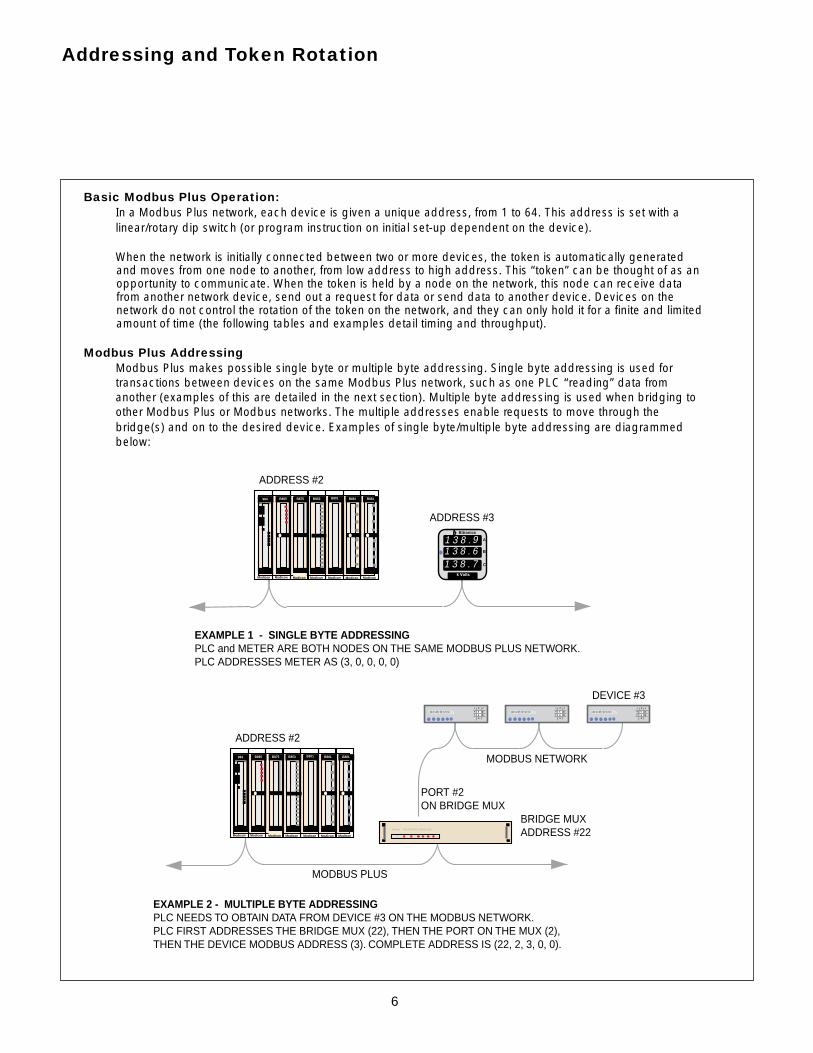
Basic Modbus Plus Operation:In a Modbus Plus network, each device is given a unique address, from 1 to 64. This address is set with alinear/rotary dip switch (or program instruction on initial set-up dependent on the device).
When the network is initially connected between two or more devices, the token is automatically generatedand moves from one node to another, from low address to high address. This “token” can be thought of as anopportunity to communicate. When the token is held by a node on the network, this node can receive datafrom another network device, send out a request for data or send data to another device. Devices on thenetwork do not control the rotation of the token on the network, and they can only hold it for a finite and limitedamount of time (the following tables and examples detail timing and throughput).
Addressing and Token Rotation
Modbus Plus makes possible single byte or multiple byte addressing. Single byte addressing is used fortransactions between devices on the same Modbus Plus network, such as one PLC “reading” data fromanother (examples of this are detailed in the next section). Multiple byte addressing is used when bridging toother Modbus Plus or Modbus networks. The multiple addresses enable requests to move through thebridge(s) and on to the desired device. Examples of single byte/multiple byte addressing are diagrammedbelow:
Modbus Plus Addressing
ADDRESS #2
ADDRESS #3
EXAMPLE 1 - SINGLE BYTE ADDRESSINGPLC and METER ARE BOTH NODES ON THE SAME MODBUS PLUS NETWORK.PLC ADDRESSES METER AS (3, 0, 0, 0, 0)
EXAMPLE 2 - MULTIPLE BYTE ADDRESSINGPLC NEEDS TO OBTAIN DATA FROM DEVICE #3 ON THE MODBUS NETWORK.PLC FIRST ADDRESSES THE BRIDGE MUX (22), THEN THE PORT ON THE MUX (2),THEN THE DEVICE MODBUS ADDRESS (3). COMPLETE ADDRESS IS (22, 2, 3, 0, 0).
ADDRESS #2
BRIDGE MUXADDRESS #22
PORT #2ON BRIDGE MUX
MODBUS PLUS
MODBUS NETWORK
DEVICE #3
1 3 8 .9
k Volts
A
B
C
bb Bitronics
1 3 8 . 61 3 8 . 7
9
138.4 kVolts
1 2 3
4 5 6
7 8 90
Modicon NW BM85D002 BRIDGE MUX
B853
Modicon
984MODEL 385
B881 B881 B801 B875 B885
Modicon Modicon Modicon Modicon Modicon Modicon
138.4 kVolts
1 2 3
4 5 6
7 8 90
138.4 kVolts
1 2 3
4 5 6
7 8 90
B853
Modicon
984MODEL 385
B881 B881 B801 B875 B885
Modicon Modicon Modicon Modicon Modicon Modicon
7
The “MSTR” Programming Block
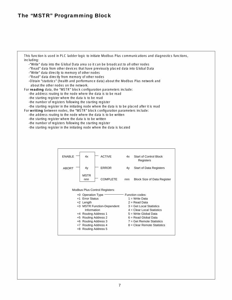
Modbus Plus Control Registers:
Operation Type Error Status Length MSTR Function-Dependent Information Routing Address 1 Routing Address 2 Routing Address 3 Routing Address 4 Routing Address 5
+0 +1 +2 +3
+4 +5 +6 +7 +8
Function codes: 1 = Write Data 2 = Read Data 3 = Get Local Statistics 4 = Clear Local Statistics 5 = Write Global Data 6 = Read Global Data 7 = Get Remote Statistics 8 = Clear Remote Statistics
ENABLE 4x ACTIVE 4x Start of Control BlockRegisters
ABORT 4y ERROR 4y Start of Data Registers
MSTR nnn COMPLETE nnn Block Size of Data Register
This function is used in PLC ladder logic to initiate Modbus Plus communications and diagnostics functions,including:
-“Write” data into the Global Data area so it can be broadcast to all other nodes-“Read” data from other devices that have previously placed data into Global Data-“Write” data directly to memory of other nodes-“Read” data directly from memory of other nodes-Obtain “statistics” (health and performance data) about the Modbus Plus network and about the other nodes on the network.
For reading data, the “MSTR” block configuration parameters include:-the address routing to the node where the data is to be read-the starting register where the data is to be read-the number of registers following the starting register-the starting register in the initiating node where the data is to be placed after it is read
For writing between nodes, the “MSTR” block configuration parameters include:-the address routing to the node where the data is to be written-the starting register where the data is to be written-the number of registers following the starting register-the starting register in the initiating node where the data is located
8
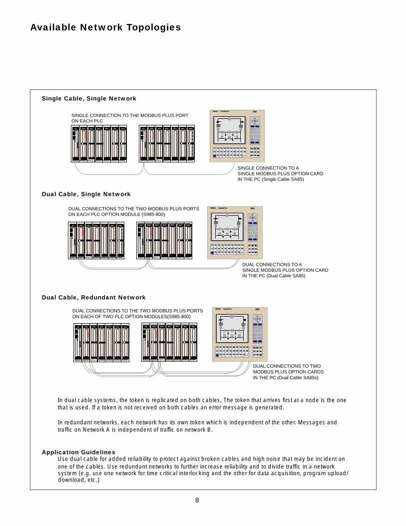
Single Cable, Single Network
Dual Cable, Single Network
Dual Cable, Redundant Network
In dual cable systems, the token is replicated on both cables. The token that arrives first at a node is the onethat is used. If a token is not received on both cables an error message is generated.
In redundant networks, each network has its own token which is independent of the other. Messages andtraffic on Network A is independent of traffic on network B.
Application GuidelinesUse dual cable for added reliability to protect against broken cables and high noise that may be incident onone of the cables. Use redundant networks to further increase reliability and to divide traffic in a networksystem (e.g. use one network for time critical interlocking and the other for data acquisition, program upload/download, etc.)
B853
Modicon
984MODEL 385
B881 B881 B801 B875 B885
Modicon Modicon Modicon Modicon Modicon Modicon
B853
Modicon
984MODEL 385
B881 B881 B801 B875 B885
Modicon Modicon Modicon Modicon Modicon Modicon
SINGLE CONNECTION TO ASINGLE MODBUS PLUS OPTION CARDIN THE PC (Single Cable SA85)
SINGLE CONNECTION TO THE MODBUS PLUS PORTON EACH PLC
Available Network Topologies
DUAL CONNECTIONS TO ASINGLE MODBUS PLUS OPTION CARDIN THE PC (Dual Cable SA85)
DUAL CONNECTIONS TO THE TWO MODBUS PLUS PORTSON EACH PLC OPTION MODULE (S985-800)
B853
Modicon
984MODEL 385
B881 B881 B801 B875 B885
Modicon Modicon Modicon Modicon Modicon Modicon
B853
Modicon
984MODEL 385
B881 B881 B801 B875 B885
Modicon Modicon Modicon Modicon Modicon Modicon
DUAL CONNECTIONS TO TWOMODBUS PLUS OPTION CARDSIN THE PC (Dual Cable SA85s)
DUAL CONNECTIONS TO THE TWO MODBUS PLUS PORTSON EACH OF TWO PLC OPTION MODULES(S985-800)
B853
Modicon
984MODEL 385
B881 B881 B801 B875 B885
Modicon Modicon Modicon Modicon Modicon Modicon
B853
Modicon
984MODEL 385
B881 B881 B801 B875 B885
Modicon Modicon Modicon Modicon Modicon Modicon

9
Bridging Between Two Modbus Plus Networks
NETWORK #1NETWORK #2
BRIDGE PLUS
SCADA RTU PLC
B853
Modicon
984MODEL 385
B881 B881 B801 B875 B885
Modicon Modicon Modicon Modicon Modicon Modicon
B853
Modicon
984MODEL 385
B881 B881 B801 B875 B885
Modicon Modicon Modicon Modicon Modicon Modicon
B853
Modicon
984MODEL 385
B881 B881 B801 B875 B885
Modicon Modicon Modicon Modicon Modicon Modicon
B853
Modicon
984MODEL 385
B881 B881 B801 B875 B885
Modicon Modicon Modicon Modicon Modicon Modicon
B853
Modicon
984MODEL 385
B881 B881 B801 B875 B885
Modicon Modicon Modicon Modicon Modicon Modicon
B853
Modicon
984MODEL 385
B881 B881 B801 B875 B885
Modicon Modicon Modicon Modicon Modicon Modicon
B853
Modicon
984MODEL 385
B881 B881 B801 B875 B885
Modicon Modicon Modicon Modicon Modicon Modicon
B853
Modicon
984MODEL 385
B881 B881 B801 B875 B885
Modicon Modicon Modicon Modicon Modicon Modicon
E
CNORMAFAIPICKURECLOSER
SYSTEM
TIMINSTANTANEOFREQUENCNEGATIVE
TARGET
STATU TARGET
ABCN
DP2000
NetworPartneV1.
Modicon NW BM85D002 BRIDGE MUX
E
CNORMAFAIPICKURECLOSER
SYSTEM
TIMINSTANTANEOFREQUENCNEGATIVE
TARGET
STATU TARGET
ABCN
DP2000
NetworPartneV1.
E
CNORMAFAIPICKURECLOSER
SYSTEM
TIMINSTANTANEOFREQUENCNEGATIVE
TARGET
STATU TARGET
ABCN
DP2000
NetworPartneV1.
E
CNORMAFAIPICKURECLOSER
SYSTEM
TIMINSTANTANEOFREQUENCNEGATIVE
TARGET
STATU TARGET
ABCN
DP2000
NetworPartneV1.
E
CNORMAFAIPICKURECLOSER
SYSTEM
TIMINSTANTANEOFREQUENCNEGATIVE
TARGET
STATU TARGET
ABCN
DP2000
NetworPartneV1.
E
CNORMAFAIPICKURECLOSER
SYSTEM
TIMINSTANTANEOFREQUENCNEGATIVE
TARGET
STATU TARGET
ABCN
DP2000
NetworPartneV1.
E
CNORMAFAIPICKURECLOSER
SYSTEM
TIMINSTANTANEOFREQUENCNEGATIVE
TARGET
STATU TARGET
ABCN
DP2000
NetworPartneV1.
It is sometimes desirable to satisfy system speed and throughput requirements through the use of twoseparate Modbus Plus networks instead of one, with different devices on each network. In these systems,each network generates its own token and the Bridge Plus router makes it possible to move data from onenetwork to another.
Below is an example of two separate Modbus Plus networks operating as one system:
In this system, network #1 is used to obtain less time critical analogs from relays (for the SCADA RTU PLC),and to keep MMI screens refreshed with new analog data. Relay configurations can also be uploaded anddownloaded. Response time can be variable, based upon traffic, in the order of 50 to 300mS.
Modbus Plus network #2 is used for fast interlocking between PLCs with throughput in the order of 10 to20mS.
The Bridge Plus makes it possible for any device on either network to obtain data from any device on the othernetwork. An example of this would be breaker status and alarm information from the Network #2 PLCs beingwritten to the SCADA RTU PLC on Network #1.

10
Twisted Pair and Fiber Optic Media
Modbus Plus networks can be made up of shielded twisted pair medium, fiber optic medium or a combinationof these two.
Three types of shielded twisted pair are available for Modbus Plus:-Modicon-specification Belden cable in 100, 500 or 1000, 1500, 2000 and 5000 foot rolls-Modicon “Super Cable”, FT4, FT6, plenum rated, direct burial in a variety of lengths-A Modbus Plus compatible steel jacketed cable is also available from Belden
Three Modbus Plus fiber optic modems are currently certified and available:-The Modicon FR85D200 125VDC 19” rack mountable line drop modem-Fiber Options 291M ModConnect Partner modem (available -20C to +60C and 125VDC)-Weed Fiber Optics Series 6000 ModConnect Partner modem
All of the above modems can handle relatively short point-to-point runs (less than 5000 feet) without difficulty.However, performance will vary between manufacturers where distance get longer and network topologiesbecome complicated. Please consult your local Application Engineer for more information.
Installation Guidelines for SubstationsThe standard twisted shielded pair is suggested for substation control room installations where distances areless than 1500 feet per network segment.
The Modbus Plus “Super Cable” is recommended for substation yard applications where direct burial ofcabling in trenches is desired. Theoretically, cable run lengths can be up 1500 feet, however, high noise andground rise possibilities may limit recommended lengths to less than 500 feet.
Note: there are about three dozen installations of this cable in distribution substations, each with cable rundistances of 200 to 300 feet (about feet 200 maximum radial distance from the control room). No problemshave been experienced in any of these systems.
Fiber optic cable should be used where distances are long or where the noise or ground potential rise isknown to be unusually high.
Twisted pair and fiber optic can be combined in a hybrid system to keep hardware and installation costsdown. The following is a suggested hybrid twisted pair and fiber optic system:
FIBEROPTIC
MODBUS PLUS TWISTED PAIR
MODBUS PLUS TWISTED PAIR
CONTROL ROOM
1 3 8 .9
k Volts
A
B
C
bb Bitronics
1 3 8 . 61 3 8 . 7
9
B853
Modicon
984MODEL 385
B881 B881 B801 B875 B885
Modicon Modicon Modicon Modicon Modicon Modicon
1 3 8 .9
k Volts
A
B
C
bb Bitronics
1 3 8 . 61 3 8 . 7
9
1 3 8 .9
k Volts
A
B
C
bb Bitronics
1 3 8 . 61 3 8 . 7
9
1 3 8 .9
k Volts
A
B
C
bb Bitronics
1 3 8 . 61 3 8 . 7
9
Modicon NW BM85D002 BRIDGE MUX
Modicon NW BM85D002 BRIDGE MUX
Modicon NW BM85D002 BRIDGE MUX
11
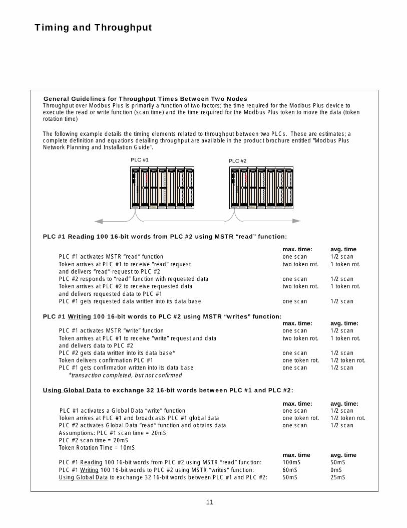
Throughput over Modbus Plus is primarily a function of two factors; the time required for the Modbus Plus device toexecute the read or write function (scan time) and the time required for the Modbus Plus token to move the data (tokenrotation time)
The following example details the timing elements related to throughput between two PLCs. These are estimates; acomplete definition and equations detailing throughput are available in the product brochure entitled "Modbus PlusNetwork Planning and Installation Guide".
PLC #1 Reading 100 16-bit words from PLC #2 using MSTR “read” function:
max. time: avg. timePLC #1 activates MSTR “read” function one scan 1/2 scanToken arrives at PLC #1 to receive “read” request two token rot. 1 token rot.and delivers “read” request to PLC #2PLC #2 responds to “read” function with requested data one scan 1/2 scanToken arrives at PLC #2 to receive requested data two token rot. 1 token rot.and delivers requested data to PLC #1PLC #1 gets requested data written into its data base one scan 1/2 scan
PLC #1 Writing 100 16-bit words to PLC #2 using MSTR “writes” function:max. time: avg. time:
PLC #1 activates MSTR “write” function one scan 1/2 scanToken arrives at PLC #1 to receive “write” request and data two token rot. 1 token rot.and delivers data to PLC #2PLC #2 gets data written into its data base* one scan 1/2 scanToken delivers confirmation PLC #1 one token rot. 1/2 token rot.PLC #1 gets confirmation written into its data base one scan 1/2 scan *transaction completed, but not confirmed
Using Global Data to exchange 32 16-bit words between PLC #1 and PLC #2:
max. time: avg. time: PLC #1 activates a Global Data “write” function one scan 1/2 scan
Token arrives at PLC #1 and broadcasts PLC #1 global data one token rot. 1/2 token rot.PLC #2 activates Global Data “read” function and obtains data one scan 1/2 scanAssumptions: PLC #1 scan time = 20mSPLC #2 scan time = 20mSToken Rotation Time = 10mS
max. time avg. timePLC #1 Reading 100 16-bit words from PLC #2 using MSTR “read” function: 100mS 50mSPLC #1 Writing 100 16-bit words to PLC #2 using MSTR “writes” function: 60mS 0mSUsing Global Data to exchange 32 16-bit words between PLC #1 and PLC #2: 50mS 25mS
Timing and Throughput
General Guidelines for Throughput Times Between Two Nodes
B853
Modicon
984MODEL 385
B881 B881 B801 B875 B885
Modicon Modicon Modicon Modicon Modicon Modicon
B853
Modicon
984MODEL 385
B881 B881 B801 B875 B885
Modicon Modicon Modicon Modicon Modicon Modicon
PLC #1 PLC #2

12
Calculating Token Rotation Time
Token Rotation time is a primarily a function of two factors; the number of nodes on the Modbus Plus networkand the amount of data being transferred by each node. The following chart can be used to estimate tokenrotation times:
Token Regeneration Time
Token Regeneration Time
When a Modbus Plus node leaves the Modbus Plus network, the token rotation sequence must bere-established with the new number of nodes, typically within 100mS. If this amount of time is greater than theprocess can tolerate, and the probability of its occurrence during critical operations is considered too high,dual controller / redundant network architectures should be considered.
Timing and Throughput (continued)
500
400
300
200
100
5 10 15 20 25 30
TIME(mS)
NUMBER OF MODBUS PLUS NODES
F
E
D
C
BA
TOKEN ROTATION TIMELEGEND:
A TOKEN ONLY
B EACH NODE TRANSFERRING 32 REGISTERS OF GLOBAL DATA
C EACH NODE TRANSFERRING 32 REGISTERS OF GLOBAL DATA AND READING OR WRITING 100 REGISTERS TO ANOTHER NODE
D EACH NODE TRANSFERRING 32 REGISTERS OF GLOBAL DATA AND READING OR WRITING 200 REGISTERS TO ANOTHER NODE
E EACH NODE TRANSFERRING 32 REGISTERS OF GLOBAL DATA AND READING OR WRITING 300 REGISTERS TO ANOTHER NODE
F EACH NODE TRANSFERRING 32 REGISTERS OF GLOBAL DATA AND READING OR WRITING 400 REGISTERS TO ANOTHER NODE

13
Enhancing Modbus Plus Throughput
1. Use Global Data. Global Data will result in the shortest time to deliver data from one node to another. In addition, programming will be simplified; once a node places data into its Global Data area, this dataautomatically gets transferred to all other Modbus Plus nodes. These nodes only have to move the data fromthe Global Data area to active memory area to use the data. You can broadcast up to 32 registers using thenetwork’s global data base, with up to 63 nodes receiving this data during the current token pass. The use ofGlobal Data can increase throughput between nodes by 50 to 60% compared to the use of MSTR “reads and“writes”.
2. Use peer-to-peer communication techniques, rather than master-slave polling. Design thesystem to have Modbus Plus devices send information only when things change, rather than having theoperator interface or other devices check all the time. This reduces the total quantity of transactions on thenetwork, improving network performance.
3. Each controller on the network should have no more than four MSTR “read” or “write”functions active at the same time. Modbus Plus is designed with a certain number of “paths” orchannels for reading, writing and programming. The use of four or less of these paths for reading or writingmakes most efficient use of these paths and prevents messages from being placed in a queue.
4. Read or write larger blocks of data. Two MSTR “write” instructions to send 50 words each takesalmost twice as long as one “write” instruction to send 100 words. The difference between sending 50 wordsand 100 words is less than one millisecond.
5. Activate MSTR “reads” and “writes” periodically, rather than all the time. If a device onModbus Plus attempts to read or write data as often as it possibly can, it will likely place data on the ModbusPlus network more often than is needed. For example, if a PLC with a 20mS scan time is set up with a timer towrite 100 words of analog data to another PLC every 300mS, the traffic on the network will be reduced by afactor of about 15 times, compared to the same PLC writing as often as it can.
6. Use more than one Modbus Plus network, with a bridge in between, to divide network traffic. Onenetwork could handle the higher speed, time critical interlocks, while the other could handle slower, dataintensive program or file uploads and downloads. The bridge makes it possible for devices on one network toobtain data from the other network.
Timing and Throughput (continued)
14
All Modbus Plus products are provided with a variety of diagnostic and troubleshooting tools, including:
1. A flashing Modbus Plus status light. The frequency and pattern of flashes provides a simple way ofdetermining network health. The following are a few of the diagnostic blinking codes:
Six flashes per second, continuousThe Modbus Plus device (or “node”) is properly communicating on the network
Four flashes, then off for 1.4 secondsThe Modbus Plus node has heard a valid message from another node having the same address
Three flashes, then off for 1.7 secondsThe Modbus Plus node finds no other nodes on the network
Two flashes, then off for 2 secondsThe Modbus Plus node finds other nodes on the network, but is not receiving the token
One flash per secondThe Modbus Plus node is initializing and should go into one of the four states above in five seconds (max.)
2. The “Get Local Statistics” and “Get Remote Statistics” Functions, which enable ModbusPlus devices to monitor network activity, including the health of other devices on the network, number ofsuccessful token rotations, retries and the token rotation time.
3. The “MBP Stat” utility, provided with the optional Modbus Plus adapters used to connect PCs andWorkstations to Modbus Plus. This utility graphically shows the type of Modbus Plus devices attached to thenetwork, their address, number of successful token rotations, retries, token rotation times and other diagnosticfunctions.
4. Confirmation of transactions. “Reads” and “writes” between devices are monitored and confirmedfor “active”, “complete” or “error”. These confirmations are accessible in real time by the Modbus Plus deviceand can be used for alarming or alternate routing of Modbus Plus messages.
Network Diagnostics and Troubleshooting
15
ModConnect Partners Program
This program is a worldwide affiliation of automation suppliers thatoffer hardware and software to complement the Modicon productline. This program has made it possible to expand into new marketsand new applications, such as Substation Automation, by “openingup” Modicon technology to key suppliers to the utility industry.
1. ModConnect Automation Partner - Designs and builds products with native Modicon technology,such as Modbus Plus networking, remote I/O networking and I/O modules. Some of our Substation Automationpartners include:
-Bitronics (Instruments on Modbus Plus)-Doble Engineering (INSITE on Modbus Plus)-ABB Power T&D (Protective relays on Modbus Plus)-Monaghan Engineering (800-Series Sequence of Events Recording Module)-Fiber Options (Fiber optic modems for Modbus Plus and Remote I/O)-Weed Fiber Optics (Fiber optic modems for Modbus Plus and Remote I/O)-Niobrara R&D ("MEB" module for Modbus Plus to Sy/Max or Modbus Plus to Ethernet-AdVoTech (Voice annunciation and Supervisory Controller)-Pro-Log (STD bus gateway interface)-Pro-Optical Technologies (Fiber Optic coupled device 800-Series I/O Module)-RACO Manufacturing (Message and alarm annunciation, gateway autodialer)
ModConnect Partnership agreements are currently being negotiated between two other manufacturers ofprotective relays and a supplier of relay protocol conversion software.
2. ModConnect Software Supplier - Markets, sells and supports its own software solutions whichleverage Modicon Products. Some of our partners in Substation automation include:
-CimQuest (PC-Based MB+ Drivers for Windows and software systems engineering)-NovaTech (Protocol conversion drivers for SCADA and relay protocols)-NovaTech (Report-By-Exception Software)-System Integration Specialists Company (SISCO) (UCA/MMS to Modbus Plus Software and
software systems engineering)-Cycle (UCA/MMS to Modbus Plus Software and software systems engineering)-US Data, WonderWare and Intellution (among many other MMI software companies)-Artec Systems (Device drivers for Modbus Plus)-Commercial Timesharing (UNIX device drivers for Modbus Plus)-S-S Technologies (Device drivers for Modbus Plus)
The ModConnect Partners program ensures compatibility between different vendors by including completetesting for compliance.
Please call Ken Georgevits at (508) 975-9113 (fax 9157) for additional information on the ModConnect PartnerProgram.
Complementary automation suppliers can participate in the ModConnect Partners Program via either of tworelationships:

16
A. Modbus Plus Between External Remote Devices and Other Substation IEDs
Using the Modicon Bridge Mux as a SCADA communications interface
DIAGNOSTIC PORT ONBRIDGE MUX FOR PC-BASED TROUBLESHOOTING
Modicon NW BM85D002 BRIDGE MUX
TO SCADA HOSTVIA MODEM
TO PLCs, PROTECTIVE RELAYSOPERATOR INTERFACES andOTHER DEVICES ON MOBDUS PLUS
TO OTHER REMOTE DEVICES;DIAL-IN OR DIAL-OUT BY EXCEPTION
BM85D00219” RACK MOUNT125VDC BRIDGE MUX
N o v a T e c hLandis and Gyr 8979Protocol Diagnostics
In these applications, the Modicon Bridge Mux serves as a protocol translator, data concentrator, and deviceto diagnose communications.
Protocol conversion is accomplished by a user-written “C” program. Available protocol conversionpackages include:
-Landis and Gyr 8979 -CDC Type I and Type II-Conitel 300, 2000, 2020 -GTAC-Harris 5000 and 6000 -BTAC
Although most protocol conversion work is performed by Modicon partners such as NovaTech and UniversalDynamics, complete development packages are available for any user.
Data Concentration is accomplished by the Bridge Mux. The Mux acquires discrete and analog data fromIEDs via Modbus Plus and also sends commands to operate devices over Modbus Plus.
The techniques for acquiring these data over Modbus Plus include:-IEDs directly writing into the Bridge Mux’s data base by exception-The Bridge Mux directly reading other IED’s data base-IEDs placing data into their Modbus Plus Global Data memory area (up to 512 bits or (32) 16-bit words).
When data are placed in the Global Data area, they become available to the Bridge Mux as well as all deviceson the Modbus Plus network
A PC-based diagnostics system is provided in NovaTech host SCADA interface systems that enablesthe user to fully diagnose and debug communications on both sides of the Bridge Mux.
For more information, please call Buzz Zey at NovaTech, Lenexa, KS at (913) 451-1880, fax 2845.
For a more complete description of the Bridge Mux, please refer to the following documents:
-”Modbus Plus Network Planning and Installation Guide”, #890 USE 100 00 Version 2.0-”The Bridge Mux and Substation Automation” (Available on CompuServe in the Modicon
Forum Library)For more information, please call Buzz Zey at NovaTech, Lenexa, KS at (913) 451-1880, fax 2845.

17
MODBUS PLUS TOOTHER DEVICES
PHONE LINE IN
OTHER INPUT AND OUTPUT MODULESfor MODICON COMPACT 984
CABLE TOMODBUS PORT
MONAGHAN ENGINEERINGPROTOCOL ADAPTOR
P120AEG
Using a PLC with an Optional PLC Module as a SCADA Communications Interface
Monaghan Engineering, a ModConnect Partner, produces an 800-Series and a Compact 984 option modulethat performs SCADA protocol conversion and includes a Bell 202 modem. Shown below is the application ofthis module in a Compact 984 PLC system.
The basic operation is as follows:-SCADA messages from the SCADA host (data “reads” and operation commands) are received by the
Monaghan protocol converter over the phone line.-The messages are converted to Modbus messages (“read” register and “write” register).-The module is connected to the Modbus port on the 984 PLC by a short RS232 cable-The PLC responds to the Modbus message by delivering the requested data or sending a control command to
the appropriate IED
In these applications, the PLC acquires discrete and analog data from IEDs via Modbus Plus. The PLC alsosends commands to operate devices over Modbus Plus.
The techniques for acquiring these data over Modbus Plus include:-IEDs directly writing into the PLC’s data base by exception-The PLC directly reading other IED’s data base-IEDs placing data into their Modbus Plus Global Data memory area (up to 512 bits or 32 16-bit words).
When data are placed in the Global Data area, they become available to the PLC and all other devices on the Modbus Plus network that support Global Data.
The acquired data are stored in the PLC data registers. Control commands are sent to substation IEDs by the PLC.
Protocols Supported:Conitel 2000 / 2020 / 300PERT 26 /31Harris HR6000 DCA
Please call Monaghan Engineering at 713-859-5205 (fax 1161) for more information.
A. Modbus Plus Between External Remote Devices and Other Substation IEDs (continued)
18
B. Modbus Plus Between ModConnect Partner Products and Other Substation IEDs
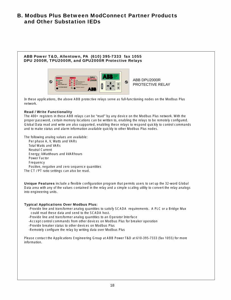
In these applications, the above ABB protective relays serve as full-functioning nodes on the Modbus Plusnetwork.
Read / Write FunctionalityThe 400+ registers in these ABB relays can be “read” by any device on the Modbus Plus network. With theproper password, certain memory locations can be written to, enabling the relays to be remotely configured.Global Data read and write are also supported, enabling these relays to respond quickly to control commandsand to make status and alarm information available quickly to other Modbus Plus nodes.
The following analog values are available:Per phase A, V, Watts and VARsTotal Watts and VARsNeutral CurrentEnergy; kWatthours and kVARhoursPower FactorFrequencyPositive, negative and zero sequence quantities
The CT / PT ratio settings can also be read.
Unique Features include a flexible configuration program that permits users to set up the 32-word GlobalData area with any of the values contained in the relay and a simple scaling utility to convert the relay analogsinto engineering units.
Typical Applications Over Modbus Plus:-Provide line and transformer analog quantities to satisfy SCADA requirements. A PLC or a Bridge Mux
could read these data and send to the SCADA host.-Provide line and transformer analog quantities to an Operator Interface-Accept control commands from other devices on Modbus Plus for breaker operation-Provide breaker status to other devices on Modbus Plus-Remotely configure the relay by writing data over Modbus Plus
Please contact the Applications Engineering Group at ABB Power T&D at 610-395-7333 (fax 1055) for moreinformation.
ABB Power T&D, Allentown, PA (610) 395-7333 fax 1055DPU 2000R, TPU2000R, and GPU2000R Protective Relays
NORMALFAILPICKUPRECLOSER OUT
SYSTEM RESET
TIMEINSTANTANEOUSFREQUENCYNEGATIVE SEQUENCE
TARGET RESET
STATUS TARGETS
ABCN
DPU2000R
NetworkPartnerV1.0
ABB DPU2000RPROTECTIVE RELAYC
E

19
k Volts
A
B
C
bb Bitronics
BITRONICSPOWERPLEX
BITRONICSMULTICOMM
1 3 8 . 91 3 8 . 91 3 8 . 9
POWER
bb Bitronics, IncLehigh Valley, PaMade in USA
CURRENT INPUTS
VOLTAGE INPUTS POWER
PowerPlexDigital transducer
POWER STATUS
HI
LOIA IB IC
B. Modbus Plus Between ModConnect Partner Products and Other Substation IEDs (continued)
Bitronics, Inc., Lehigh Valley, PA (610) 865-2444 fax 0340MultiComm and PowerPlex Instruments
In these applications, the MultiComm and PowerPlex instruments serve as full-functioning nodes on theModbus Plus network.
Features of the MultiComm Alpha or PowerPlex include .25% accuracy on all measured values and the abilityto remotely reset energy values. The PowerPlex also permits remote setting of PT and CT ratios. The data thatcan be read from the Modbus versions of these is identical to the data available from the Modbus Plusversions of these instruments.
Read Functionality - MultiComm and PowerPlexThe following analog values can be read from Global Data or through reads by other Modbus Plus devices:
Per phase A, V, Watts and VARsTotal Watts and VARsNeutral CurrentEnergy; kWatthours and kVARhoursFrequency
The CT / PT ratio settings can also be read.
Write Functionality - MultiComm and PowerPlexIn both the MutiComm and PowerPlex, energy values can be reset by a device on Modbus Plus “writing” a reset (value “1”) to a designated instrument register. In the PowerPlex, CT and PT values can also be set byany Modbus Plus device “writing” the appropriate vales to the designated register.
Typical Applications Over Modbus Plus:-Provide line and transformer analog quantities to satisfy SCADA requirements. A PLC or a Bridge Mux
could read these data and send to the SCADA host.-Provide line and transformer analog quantities to an Operator Interface
20
B. Modbus Plus Between ModConnect Partner Products and Other Substation IEDs (continued)
MODBUS PLUS NETWORK #1
MODBUS PLUS NETWORK #2
DOBLE INSITEDATA ACQUISITION UNITS
ON SUBSTATION APPARATUS
BRIDGE PLUS
B853
Modicon
984MODEL 385
B881 B881 B801 B875 B885
Modicon Modicon Modicon Modicon Modicon Modicon
Modicon NW BM85D002 BRIDGE MUX
138.4 kVolts
1 2 3
4 5 6
7 8 90
138.4 kVolts
1 2 3
4 5 6
7 8 90
Modicon NW BM85D008 BRIDGE MUX
138.4 kVolts
1 2 3
4 5 6
7 8 90
Modicon NW BM85D002 BRIDGE MUX
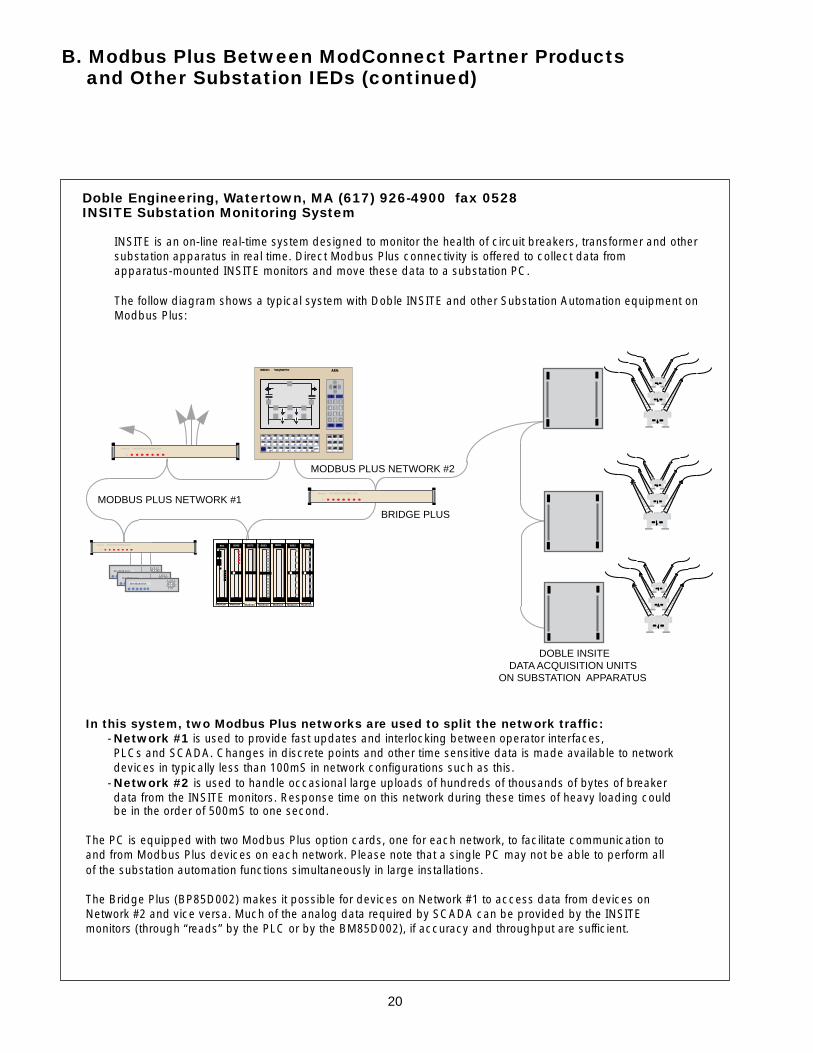
In this system, two Modbus Plus networks are used to split the network traffic:- Network #1 is used to provide fast updates and interlocking between operator interfaces,PLCs and SCADA. Changes in discrete points and other time sensitive data is made available to networkdevices in typically less than 100mS in network configurations such as this.
- Network #2 is used to handle occasional large uploads of hundreds of thousands of bytes of breakerdata from the INSITE monitors. Response time on this network during these times of heavy loading couldbe in the order of 500mS to one second.
The PC is equipped with two Modbus Plus option cards, one for each network, to facilitate communication toand from Modbus Plus devices on each network. Please note that a single PC may not be able to perform allof the substation automation functions simultaneously in large installations.
The Bridge Plus (BP85D002) makes it possible for devices on Network #1 to access data from devices onNetwork #2 and vice versa. Much of the analog data required by SCADA can be provided by the INSITEmonitors (through “reads” by the PLC or by the BM85D002), if accuracy and throughput are sufficient.
Doble Engineering, Watertown, MA (617) 926-4900 fax 0528INSITE Substation Monitoring System
INSITE is an on-line real-time system designed to monitor the health of circuit breakers, transformer and othersubstation apparatus in real time. Direct Modbus Plus connectivity is offered to collect data fromapparatus-mounted INSITE monitors and move these data to a substation PC.
The follow diagram shows a typical system with Doble INSITE and other Substation Automation equipment onModbus Plus:
21
C. Modbus Plus Between a PC (Operator Interface) and Other Substation IEDs
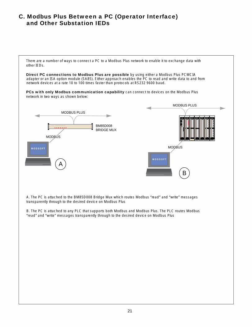
There are a number of ways to connect a PC to a Modbus Plus network to enable it to exchange data withother IEDs.
Direct PC connections to Modbus Plus are possible by using either a Modbus Plus PCMCIAadapter or an ISA option module (SA85). Either approach enables the PC to read and write data to and fromnetwork devices at a rate 10 to 100 times faster than protocols at RS232 9600 baud.
PCs with only Modbus communication capability can connect to devices on the Modbus Plusnetwork in two ways as shown below:
A
M O D S O F T
MODBUS PLUS
BM85D008BRIDGE MUX
MODBUS
MODBUS PLUS
M O D S O F T
MODBUS
B
B853
Modicon
984MODEL 385
B881 B881 B801 B875 B885
Modicon Modicon Modicon Modicon Modicon Modicon
Modicon NW BM85D002 BRIDGE MUX
A. The PC is attached to the BM85D008 Bridge Mux which routes Modbus “read” and “write” messagestransparently through to the desired device on Modbus Plus
B. The PC is attached to any PLC that supports both Modbus and Modbus Plus. The PLC routes Modbus“read” and “write” messages transparently through to the desired device on Modbus Plus
22
D. Modbus Plus in a Sequence of Events Recording (SER) System
PLC WITH SER MODULES PLC WITH SER MODULES
SYNCHRONIZATION NETWORK
MODBUS PLUS NETWORK
PC WITH SER RECORDINGSOFTWARE
B853
Modicon
984MODEL 385
B881 B881 B801 B875 B885
Modicon Modicon Modicon Modicon Modicon Modicon
B853
Modicon
984MODEL 385
B881 B881 B801 B875 B885
Modicon Modicon Modicon Modicon Modicon Modicon
SEQUENCE OF EVENTS RECORDING
-POINT CONFIRMATION
-PRINTER SETUP
-FAX SET-UP
-ADDRESS DATA BAS SETUP
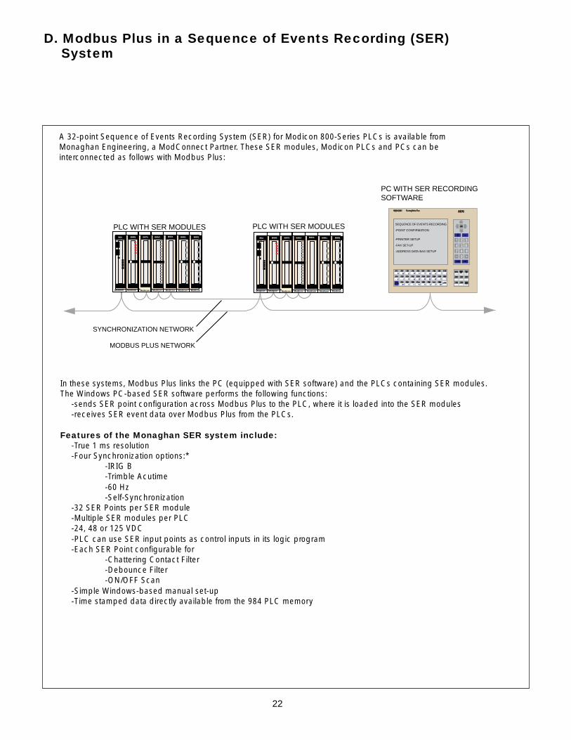
In these systems, Modbus Plus links the PC (equipped with SER software) and the PLCs containing SER modules.The Windows PC-based SER software performs the following functions:
-sends SER point configuration across Modbus Plus to the PLC, where it is loaded into the SER modules-receives SER event data over Modbus Plus from the PLCs.
Features of the Monaghan SER system include:-True 1 ms resolution-Four Synchronization options:*
-IRIG B-Trimble Acutime-60 Hz-Self-Synchronization
-32 SER Points per SER module-Multiple SER modules per PLC-24, 48 or 125 VDC-PLC can use SER input points as control inputs in its logic program-Each SER Point configurable for
-Chattering Contact Filter-Debounce Filter-ON/OFF Scan
-Simple Windows-based manual set-up-Time stamped data directly available from the 984 PLC memory
A 32-point Sequence of Events Recording System (SER) for Modicon 800-Series PLCs is available fromMonaghan Engineering, a ModConnect Partner. These SER modules, Modicon PLCs and PCs can beinterconnected as follows with Modbus Plus:

23
Modicon PLCs use two techniques to communicate over Modbus Plus.
The first technique is through the use of the “MSTR” function block to:-Read and write registers between PLCs-Read “statistics” or health of the other controller-Move data into the Global Data area so it can be written to other controllers on the network
The second technique is through the use of “Peer Cop”. Peer cop enables one PLC to use another PLC’sinput and output points as if they were its own. During configuration, certain inputs and outputs of onecontroller are “mapped” to another controller. This simplifies the programming of operations where onecontroller needs to act as a master to the other.
Please refer to the section of this document entitled “Timing and Throughput” of the analysis of the throughputbetween Modicon PLCs.
The following Modicon controllers are provided with built-in Modbus Plus communication capability:
Compact 984 Controllers-984-145-984-245 (flash-based and twice as fast as -145 above)-984-255 (extended memory version of -245 above)
984 “Slot-mount” controllers-984-385 (available in AC or 125 VDC versions)-984-485 (AC only)-985-685 (AC only)-984-785 (available in AC or 125 VDC versions)The -685 and -785 models are about twice as fast as the -385 and -485 and have larger memories
Quantum Controllers-All are available with Modbus Plus
The slot-mount 984 Controllers and Quantum controllers are also avaiable with redundant Modbus Plus cableand redundant Modbus Plus Network capability. Please refer to the section of this document entitled“Available network Topologies” for a description of these options.
E. Modbus Plus Between Modicon PLCs
24
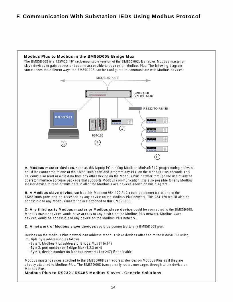
Modbus Plus to Modbus in the BM85D008 Bridge MuxThe BM85D008 is a 125VDC 19” rack-mountable version of the BM85C002. It enables Modbus master orslave devices to gain access or become accessible to devices on Modbus Plus. The following diagramsummarizes the different ways the BM85D008 can be configured to communicate with Modbus devices:
Modicon NW BM85D008 BRIDGE MUX
984-120
RS232 TO RS485
A B
C
D
M O D S O F T
BM85D008BRIDGE MUX
MODBUS PLUS
138.4 kVolts
1 2 3
4 5 6
7 8 9
0
138.4 kVolts
1 2 3
4 5 6
7 8 9
0
138.4 kVolts
1 2 3
4 5 6
7 8 9
0
138.4 kVolts
1 2 3
4 5 6
7 8 9
0
138.4 kVolts
1 2 3
4 5 6
7 8 9
0
A. Modbus master devices, such as this laptop PC running Modicon Modsoft PLC programming softwarecould be connected to one of the BM85D008 ports and program any PLC on the Modbus Plus network. ThisPC could also read or write data from any other device on the Modbus Plus network through the use of any ofoperator interface software package that supports Modbus communication. It is also possible for any Modbusmaster device to read or write data to all of the Modbus slave devices shown on this diagram.
B. A Modbus slave device, such as this Modicon 984-120 PLC could be connected to one of theBM85D008 ports and be accessed by any device on the Modbus Plus network. This 984-120 would also beaccessible to any Modbus master device attached to this BM85D008.
C. Any third party Modbus master or Modbus slave device could be connected to the BM85D008.Modbus master devices would have access to any device on the Modbus Plus network. Modbus slavedevices would be accessible to any device on the Modbus Plus network.
D. A network of Modbus slave devices could be connected to any BM85D008 port.
Devices on the Modbus Plus network can address Modbus slave devices attached to the BM85D008 using multiple byte addressing as follows:
-Byte 1, Modbus Plus address of Bridge Mux (1 to 64)-Byte 2, port number on Bridge Mux (1,2,3 or 4)-Byte 3, device number on Modbus network (1 to 247) if applicable
Modbus master devices attached to the BM85D008 can address devices on Modbus Plus as if they aredirectly attached to Modbus Plus. The BM85D008 transparently routes messages through to the device onModbus Plus.Modbus Plus to RS232 / RS485 Modbus Slaves - Generic Solutions
F. Communication With Substation IEDs Using Modbus Protocol
25
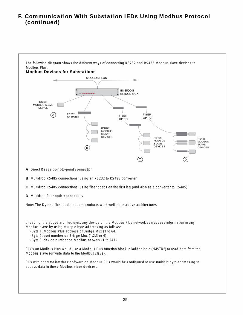
The following diagram shows the different ways of connecting RS232 and RS485 Modbus slave devices toModbus Plus:Modbus Devices for Substations
A. Direct RS232 point-to-point connection
B. Multidrop RS485 connections, using an RS232 to RS485 converter
C. Multidrop RS485 connections, using fiber optics on the first leg (and also as a converter to RS485)
D. Multidrop fiber optic connections
Note: The Dymec fiber optic modem products work well in the above architectures
In each of the above architectures, any device on the Modbus Plus network can access information in anyModbus slave by using multiple byte addressing as follows:
-Byte 1, Modbus Plus address of Bridge Mux (1 to 64)-Byte 2, port number on Bridge Mux (1,2,3 or 4)-Byte 3, device number on Modbus network (1 to 247)
PLCs on Modbus Plus would use a Modbus Plus function block in ladder logic (“MSTR”) to read data from theModbus slave (or write data to the Modbus slave).
PCs with operator interface software on Modbus Plus would be configured to use multiple byte addressing toaccess data in these Modbus slave devices.
RS485MODBUSSLAVEDEVICES
RS232TO RS485
BM85D008BRIDGE MUX
Modicon NW BM85D008 BRIDGE MUX
MODBUS PLUS
FIBEROPTIC
FIBEROPTIC
A
B
C
RS232MODBUS SLAVE
DEVICE
D
RS485MODBUSSLAVEDEVICES
RS485MODBUSSLAVEDEVICES
F. Communication With Substation IEDs Using Modbus Protocol (continued)

26
Below is a partial list of substation products that are available with the Modbus protocol.
Bitronics, Inc. InstrumentsLehigh Valley, PA (610) 865-2444 fax 0340The Bitronics MultiComm and PowerPlex instruments are available with either an RS232 Modbus slave port ortwo-wire RS485 Modbus slave port. Modbus Plus is also available on either of these instruments.
Basler Electric RelaysHighland, IL (618) 654-2341 fax 2351The Basler BE1-DFPR Distribution Protection Relay is available with either an isolated RS232 Modbus slaveport or a two-wire RS485 slave port.
ABB Power T&D Protective RelaysAllentown, PA (610) 395-7333 fax 1055The ABB DPU2000R, TPU2000R, and GPU2000R are all available with either an isolated RS232 Modbusslave port or a two-wire RS485 slave port. Modbus Plus is also available on these relays.
Power Measurement, Ltd. (PML) Power MetersVictoria, British Columbia, Canada (604) 652-5118 fax 0411The PML 3300 ACM Digital Power Meter is available with a standard RS485 Modbus slave port.
MultiLin, Inc. RelaysMarkham, Ontario, Canada (416) 294-6222 fax 8512The MultiLin 575 Feeder Protection Relay is available with a standard RS485 Modbus slave port.
Tasnet Network Interface Modules ("NIMs")Pineallas Park, FL (813) 544-1555 fax 545-8975Tasnet can provide a Modbus master NIM to read or write data to any Modbus slave device. Slaves can bePLCs or any of the other devices described on the page. Modbus master commands from the NIM also canbe routed by the BM85D008 Bridge Mux to any device on the Modbus Plus network.
Schweitzer Engineering Laboratories 2020 Communications Processor
F. Communication With Substation IEDs Using Modbus Protocol (continued)
27
F. Communication With Substation IEDs Using Modbus Protocol (continued)
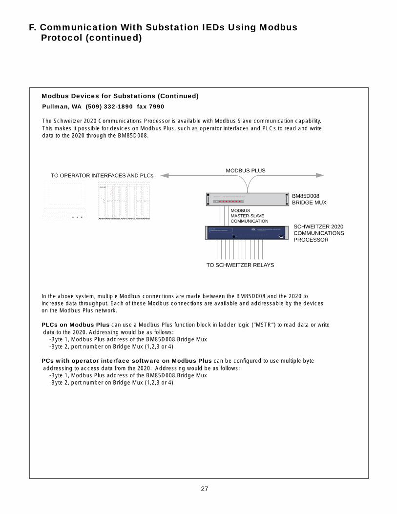
Modbus Devices for Substations (Continued)
Pullman, WA (509) 332-1890 fax 7990
The Schweitzer 2020 Communications Processor is available with Modbus Slave communication capability.This makes it possible for devices on Modbus Plus, such as operator interfaces and PLCs to read and writedata to the 2020 through the BM85D008.
In the above system, multiple Modbus connections are made between the BM85D008 and the 2020 toincrease data throughput. Each of these Modbus connections are available and addressable by the deviceson the Modbus Plus network.
PLCs on Modbus Plus can use a Modbus Plus function block in ladder logic (“MSTR”) to read data or write data to the 2020. Addressing would be as follows:
-Byte 1, Modbus Plus address of the BM85D008 Bridge Mux-Byte 2, port number on Bridge Mux (1,2,3 or 4)
PCs with operator interface software on Modbus Plus can be configured to use multiple byte addressing to access data from the 2020. Addressing would be as follows:
-Byte 1, Modbus Plus address of the BM85D008 Bridge Mux-Byte 2, port number on Bridge Mux (1,2,3 or 4)
SCHWEITZER 2020COMMUNICATIONSPROCESSOR
MODBUSMASTER-SLAVECOMMUNICATION
SCHWEITZER ENGINEERING LABORATORIESSELSEL-2020COMMUNICATIONS PROCESSOR
LED TEST
ALARM
1 2 3 4 5 6 7 8 9 10 11 12 13 14 15 16
OO
OO
OO
OO
SCHWEITZER ENGINEERING LABORATOIESPULLMAN WASHIMGTON USA
TO SCHWEITZER RELAYS
BM85D008BRIDGE MUX
Modicon NW BM85D008 BRIDGE MUX
MODBUS PLUS
B853
Modicon
984MODEL 385
B881 B881 B801 B875 B885
Modicon Modicon Modicon Modicon Modicon Modicon
M O D S O F T
TO OPERATOR INTERFACES AND PLCs

28
SCHWEITZER ENGINEERING LABORATORIES
SEL
OO
OSCHWEITZER ENGINEERING LABORATORIESPULLMAN WASHIMGTON USA
OO O
SEL-251 DISTRIBUTION RELAYFAULT TYPE
INST A B C Q N
FAULTTEST
RS LO
79PHASE OVERCURRENT RELAY WITH VOLTAGE CONTROLNEGATIVE SEQUENCE OVERCURRENT RELAYGROUNDG OVERCURRENT RELAYMULTIPLE SHOT RECLOSING RELAYSELECTANLE SETTING GROUPSCIRCUIT BREAKER MONITORFAULT LOCATOR
BM85D008BRIDGE MUX
MODBUS PLUS
B853
Modicon
984MODEL 385
B881 B881 B801 B875 B885
Modicon Modicon Modicon Modicon Modicon Modicon
M O D S O F T
TO OPERATOR INTERFACES AND PLCs
SCHWEITZER SEL-251DISTRIBUTION RELAYS
Modicon NW BM85D008 BRIDGE MUX
SCHWEITZER ENGINEERING LABORATORIES
SEL
OO
OSCHWEITZER ENGINEERING LABORATORIESPULLMAN WASHIMGTON USA
OO O
SEL-251 DISTRIBUTION RELAYFAULT TYPE
INST A B C Q N
FAULTTEST
RS LO
79PHASE OVERCURRENT RELAY WITH VOLTAGE CONTROLNEGATIVE SEQUENCE OVERCURRENT RELAYGROUNDG OVERCURRENT RELAYMULTIPLE SHOT RECLOSING RELAYSELECTANLE SETTING GROUPSCIRCUIT BREAKER MONITORFAULT LOCATOR
GEC Alsthom T&D KCEG and KCGG Protective RelaysHawthorne, NY (914) 347-5166 fax 5508
The programmable Bridge Mux BM85D002 can be provided with protocol conversion software to make itpossible for Modbus Plus devices to access data from substation IEDs in their native protocol.
Three BM85D002 software packages are currently available from NovaTech, Lenexa, KS and Universal Dynamics, Vancouver, BC, Canada for communication with the following protective relays:
Schweitzer Engineering Laboratories SEL 100, -200, and -300 Series Protective RelaysPullman, WA (509) 332-1890 fax 7990
BM85D008Modicon NW BM85D008 BRIDGE MUX
MODBUS PLUS
B853
Modicon
984MODEL 385
B881 B881 B801 B875 B885
Modicon Modicon Modicon Modicon Modicon Modicon
M O D S O F T
TO OPERATOR INTERFACES AND PLCs
KITZ 101COMMUNICATIONPROCESSOR
RS485
GEC KCCG or KCEGPROTECTIVE RELAYS
00 00
00 00
G. Communication With Substation IEDs Using Native Protocols

29
PROGRAMMABLEBM85D002 BRIDGE MUX
MODBUS PLUS
B853
Modicon
984MODEL 385
B881 B881 B801 B875 B885
Modicon Modicon Modicon Modicon Modicon Modicon
M O D S O F T
TO OPERATOR INTERFACES AND PLCs
ABB RELAYS
Modicon NW BM85D008 BRIDGE MUX
G. Communication With Substation IEDs Using Native Protocols (continued)
ABB Power T&D 301 / 302 Protective RelaysAllentown, PA Tel:(610) 395-7333 Fax: 1055
For additional information about interfacing to these protective relays, please contact:
NovaTech, Lenexa, KSTel: (913) 451-1880 Fax: 2845Attn: Buzz Zey
Universal Dynamics, Vancouver, BC, CanadaTel: (604) 736-3381 Fax: 3110Attn: Malcolm Cameron

30
H. Communication with Square D PowerLogic and Sy/Max PLCs
Communication between Square D PowerLogic or Sy/Max PLCs and Modbus Plus is possible through theuse of the Modicon Programmable Bridge Mux or the Niobrara R&D ModConnect module.
The Programmable Bridge Mux can be provided with a software utility to convert Modbus plus to the Sy/Maxprotocol. This makes it possible for devices on Modbus Plus to read or write data to devices on the Sy/Maxnetwork, such as PowerLogic circuit monitors or Sy/max PLCs.
Sy/Max 450- and 650-Series PLCs can be directly connected to Modbus Plus through the use of theNiobrara R&D MEB ModConnect option module. This module enables these Sy/Max CPUs to serve as full-functioning Modbus Plus nodes, able to read or write data to other Modbus Plus devices in a peer-to-peerfashion.
The following diagram summarizes the interconnections:
B853
Modicon
984MODEL 385
B881 B881 B801 B875 B885
Modicon Modicon Modicon Modicon Modicon Modicon
MODICON PLCson MODBUS PLUS
104.57
DSQUARE D
PowerLogicCIRCUIT MONITOR
AMMETER (A)VOLTMETER L L (V)VOLTMETER L N (V)WATTMETER (W)VARMETER (VA)VA METER (VA)POWER FACTOR METERFREQUENCY METER (Hz)DEMAND AMMETER (A)DEMAND POWER (W)DEMAND POWER (VA)WATT HOUR METERVARHOUR METERCURRENTVOLTAGEFACTORTOO SMALL
3 PHASEA((A B)B (B C)C (C A)N
SELECTMETER
METERSMINMAXALARM
KILOMEGA
V
V
PHASE
MODE
BRIDGINGTO SQUARE DPOWERLOGICandOTHER DEVICESCOMMUNICATING WITHSY/MAX PROTOCOL
SY/MAX M450/650 CPUsON MODBUS PLUSWITH NIOBRARA R&D MODULE
MODICONBM85D002BRIDGE MUX
SY/MAX NETWORK
Modicon NW BM85D002 BRIDGE MUX
MODBUS PLUS NETWORK

31
Registered Trademarks of AEG Schneider Automation, Inc.: Modicon, Modbus, Modbus II,P190, Modsoft.Trademarks of AEG Schneider Automation, Inc.: Modbus Plus, ModConnect, CoPro,ModSnoop, Modtools, Modfix.Registered Trademarks of International Business Machines Corporation: AT-Bus, OS/2, PS/2.Trademark of International Business Machines Corporation: Micro Channel.Registered Trademark of Digital Equipment Corporation: DEC.Trademarks of Digital Equipment Corporation: VMS, VAX, Q-Bus.Registered Trademark of Industrial Data Technologies: PanelMate.Trademark of Industrial Data Technologies: FactoryMateTrademark of AEG Westinghouse Industrial Corporation: Unicell
Copyright 1996, AEG Schneider Automation, Inc.

32
This literature is subject to change without notice. It does not necessarily reflectall aspects of the product or the service, their performance or applications.AEG Schneider Automation is not responsible for any errors or omissions inthis presentation.
From single productsto complete systems,look to Square D.
Square D Company is a leadingmanufacturer and supplier of electricaldistribution, automation and industrialcontrol products. The full line of Square D,Modicon and Telemecanique brandproducts are available from an extensivenetwork of Square D distributors locatedthroughout North America.
Square D Company is part of GroupeSchneider, a global manufacturer of electricaldistribution, automation and industrialequipment.
Square D has been serving industrialand construction markets, as well as publicutilities, individual consumers and governmentagencies for over 90 years. We offerunsurpassed quality, innovative design anda committed staff of trained sales represen-tatives and service technicians willing tostand behind every product we sell.
For further information on how we canhelp fill your electrical needs, call your localSquare D field representative or authorizedSquare D distributor.