modbus’” - kollmorgen · modbus asfb software package 1 .i introduction the modbus asfb...
TRANSCRIPT

.-
Modbus’” ”Application Specific Function Block Manual
GIDDINCS & LEWIS@

NOTE
Progress is an ongoing commitment at Giddings & Lewis. We continually strive to offer the mostadvanced products in the industry; therefore, information in this document is subject to changewithout notice. The illustrations and specifications are not binding in detail. Giddings & Lewis shallnot be liable for any technical or editorial omissions occurring in this document, nor for anyconsequential or incidental damages resulting from the use of this document.
DO NOT ATTEMPT to use any Giddings & Lewis product until the use of such product iscompletely understood. It is the responsibility of the user to make certain proper operation practicesare understood. Giddings & Lewis products should be used only by qualified personnel and for theexpress purpose for which said products were designed.
Should information not covered in this document be required, contact the Customer ServiceDepartment, Giddings & Lewis, 666 South Military Road, P.O. Box 1658, Fond du Lac, WI 54936-1658. Giddings & Lewis can be reached by telephone at (414) 921-7100.
401-55378-00
Version 2 - 1497
0 1993 - 1997 Giddings & Lewis, Inc. DB2-3469
Modbus, 984, BM85, S985,685 are trademarks of the Modicon Company.IBM@ is a registered trademark of International Business Machines CorporationIBM AT is a trademark of International Business Machines CorporationPiC900, PiC90, and PiCPro are registered trademarks of Giddings & Lewis, Inc.
BA2244a9

Table of Contents
Application Specific Function Block GuidelinesInstallation ..........................................................................................................Revisions ............................................................................................................ASFB Input/Output Descriptions .......................................................................Using ASFBs ......................................................................................................
Modbus ASFB Software Package
1.1 Introduction ...............................................................................................................Background on Modbus protocol .......................................................................
1.2 Requirements ............................................................................................................Hardware requirements ....................................................................................Cable connections ..............................................................................................Software requirements ......................................................................................Compatibility ......................................................................................................
1.3 Installation ..............................................................................................................1.4 Modbus Function Block ..........................................................................................
C-MODMST ......................................................................................................The ASCII Mode ..............................................................................................The RTU Mode ................................................................................................Modbus Master ..................................................................................................
’Modbus master example LDO ........................................................................C-MODMST function block setup ..................................................................C-MODSLV ......................................................................................................The ASCII Mode ..............................................................................................The RTU Mode ................................................................................................Modbus Slave ...................................................................................................Modbus slave example LDO ............................................................................C-MODSLV function block setup ...................................................................
. Index
5688899
111213173.8212225262930313234
Table of Contents 1

NOTES
2 Table of Contents

Awlication Specific Function Block Guidelines
Installation
The following guidelines are recommended ways of working with ApplicationSpecific Function Blocks (ASFBs) from Giddings & Lewis.
1. Make a back up copy of the ASFB disk you receive and store the originalin a safe place.
2. The disk you receive with the ASFB package will include the following:1. ASFBS directory containing:
l .LIB file(s) containing the ASFB(s)l source .LDO(s) from which the ASFB(s) was made
2. EXAMPLES directory containing:l example LDO(s) with the ASFB(s) incorporated into the ladder
which you can then use to begin programming from or merge withan existing application ladder
It is recommended that you copy the .LIB and the source LDO files toyour hard drive on the PC in the following way. Remember that ASFBlibraries (.LIB) files and source (.LDO) files must be kept in the samedirectory.l Create a directory that will hold all ASFB LIBs and source LDOs.
For example, you may have the Motion ASFB package and theCommunication ASFB package. Copy the appropriate files on thedisks to a directory on your PC called ASFB.When you installed PiCPro, the PiCLib statement was automaticallyentered in your autoexec.bat file as shown below:
SET PICLIB=C:\PICLIBNOTE: If you chose to alter your PICLIB statement duringinstallation, it will look different than what appears above.Now add the ASFB directory to your PICLIB = statement as shownbelow:
SET PICLIB=C:\PICLIB;C:\ASFBl Put the example file(s) in your working directory.
For example, if you always run PiCPro from the directory which holdsall your LDO files, then copy all the ASFB example LDOs to the LDOdirectory.
Application Specific Function Block Guidelines 1
Revisions
3. The first three networks of each ASFB source ladder provide the followinginformation.
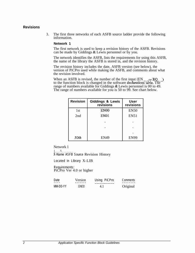
Network 1The first network is used to keep a revision history of the ASFB. Revisionscan be made by Giddings & Lewis personnel or by you.The network identifies the ASFB, lists the requirements for using this ASFB,the name of the library the ASFB is stored in, and the revision history.The revision history includes the date, ASFB version (see below), theversion of PiCPro used while making the ASFB, and comments about whatthe revision involved.When an ASFB is revised, the number of the first input (EN or RQ- 3to the function block is changed in the software declarationst~ble. Therange of numbers available for Giddings & Lewis personnel is 00 to 49.The range of numbers available for you is 50 to 99. See chart below.
Revision
1st EN002nd EN01
50th
Giddings & Lewisrevisions
.
.
EN49
Userrevisions
EN50EN51
EN99
Network 1I...1 f......X-Name ASFB Source Revision History
Located in Library X-LIB
Requirements:PiCPro Ver 4.0 or higher
Date- - - -MM-DD-YY
Version Using PiCPro Comments- - - - - - - -----__-_-__ - - - - - - - -
EN00 4.1 Original
2 Application Specific Function Block Guidelines

Network 2The second network describes what you should do if you want to make arevision to the ASFB.
1..
If you revise the ASFB, do the following:
1. Do a ‘M’odule, save ‘A’s in order to save the original ASFB beforeyou begin modifying.
2. Change the number on the first input to the ASFB in the softwaredeclarations table to a 50 or greater (for example, EN00 would bechanged to EN50).
3. Update the revision history in network 1.
ASFB Input/Output Descriptions
Network 3The third network describes the ASFB and defines all the inputs andoutputs to the function block.
ASFB Description
INPUTS:
Name Data Type- - - - - - - - - - - - -EN00 BOOL
OUTPUTS:
Name Data Type- - - - ------_--OK BOOL
De f i n i t i on_----_--__enables execution
Definition
execution complete
Application Specific Function Block Guidelines 3

Using ASFBs
4. When you are ready to use the ASFB in your application, there are severalapproaches you can take as shown below.l Create a new application LDO starting with the example LDO for the
ASFB package. The advantage is that the software declarations tablefor the ASFB has been entered for you.NOTE: To keep the original example LDO, use the ‘save As’command. This copies the example LDO to an LDO with theapplication name you give it.
l If you already have an application LDO, merge the example LDO withthe application LDO using the optional LDOMERGE softwarepackage. The software declaration tables for both LDOs will alsomerge.
l Enter the ASFB into your application LDO.NOTE: This method is not recommended if the software declarationstable is lengthy. It requires that you manually enter all the inputs andoutputs to the ASFB in the table. With some packages, this is time-consuming. Any structure, array, array of structures, or strings must beentered exactly as it appears in the original table. This is critical to thecorrect functioning of the ASFB.
4 Application Specific Function Block Guidelines

Modbus ASFB Software Package
1 .I Introduction
The Modbus ASFB software package from Giddings & Lewis allows the PiC900 tocommunicate as a Modbus master or slave using the Modbus protocol. The Modbusprotocol determines how each controller on a network will know its device address,recognize a message addressed to it, determine the kind of action to be taken, andextract any data or other information contained in the message. If a reply is required,the PiC900 will construct the reply message and send it using Modbus protocol.
Communications is done using a master/slave mode. Only one device, the master,can initiate a transaction called a query. The other devices, the slaves, respond withthe data requested by the master or by taking the action specified in the query.
The PiC900 is used as a master or slave device. Communication takes place throughthe PiC900 serial ports. The serial ports include the USER PORT 2 on the CPU orthe ports on a PiC900 serial communications module (2 or 4 port models available).
The master is typically a host processor, an operator interface, or a PiC900. Themaster can address individual slaves or can initiate a broadcast message to all slaves.Slaves respond to queries that are addressed to them individually. Responses are notreturned to broadcast queries from the master. Some possible Modbus configurationsare shown in the block diagrams below.
Figure 1. Configurations for using Modbus communications
Basic connection
PiC900 used as a slave
Slave Master
PiC900Modbus
RS-232 1PC (or smartinterface device)
PiC900 used as a master
Master Slave, I I 1
L- I I
GD104933
Other possible connections
I I I I984-685 Modbus
H
PiC900(To MB Pius) (used as a slave)
--T-- Modbus Plus
pq rg - ;qModbus Modbus
Up to four PiCSOOsPiC900 or other Modbus
(used as a slave) devices/networks
GDllJJSS3
The interface devices shown in the diagram are described below.
Modbus 5

984-685 Modicon controllerAT/MC-984 IBM ATTM/Modicon controllerMM1 Man Machine Interface984 A5 Modicon controllerS985 Remote I/O busBM85 Bridge Multiplexer - Modbus Plus to Modbus bridge
Background on Modbus protocol
As shown below, the Modbus protocol establishes the format for the master query byplacing into the query message a device or broadcast address, a function codedefining the requested action, any data bytes to be sent, and an error-checking field.The slave response message contains fields confirming the action taken, any data tobe returned, and an error-checking field.
If an error occurred in receipt of the message, or if the slave is unable to perform therequested action, the slave will construct an error message and send it as its response.
The Master/Slave Query/Response Cycle
Query
Responsemessagefrom the
slaveGD12-OT53
6 Modbus
Query
Response
The code in the query tells the addressed slave device what kind of action toperform. The data bytes contain any additional information that the slave willneed to execute the command.For example, code 03 will query the slave to read holding registers and respondwith their contents. The data field must contain the information telling the slavewhich register to start at and how many registers to read. The error check fieldprovides a method for the slave to validate the query message.If the slave makes a normal response, the code in the response is an echo of thecode in the query. The data bytes contain the data collected by the slave, such asregister values or status.If an error occurs, the code is modified to indicate that the response is an errorresponse, and the data bytes contain a code that describes the error. The errorcheck field allows the master to confirm that the response message contents arevalid.
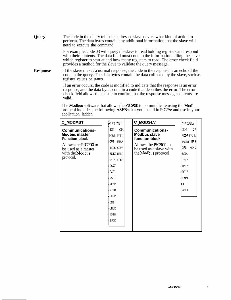
The Modbus software that allows the PiC900 to communicate using the Modbusprotocol includes the following ASFE5s that you install in PiCPro and use in yourapplication ladder.
C-MODMST
Communications-Modbus masterFunction blockAllows the PiC900 tobe used as a masterwith the Modbusprotocol.
1C-MOCtlST--EN OK
-PORT FAIL
-CFG ERA
- BOOL COMP
-BSIZ TERR
-DATA CODE
-DSIZ
-EXPT
-ASCI
-SEND
- ADDR
-FUNC
-CNT
-LNDX
- RNDX
- BROD
C-MODSLV
Communications-Modbus slavefunction blockAllows the PiC900 tobe used as a slave withthe Modbus protocol.
C-MODSLV
-EN OK-
-ADDR FAIL-
-PORT ERR-
-CFG RCMD-
-BOOL
- BSIZ
-DATA
-DSIZ
-EXPT
-R
- ASCI
Modbus 7

1.2 Requirements
The hardware and software requirements when using the Modbus interface tocommunicate with a compatible device are covered in this section.
Hardware requirements
l A PiC900 programmable industrial computer with approximately 1.3K of databytes free and approximately 11SK of ladder code bytes free.NOTE: The number of free bytes can bechecked in the Download complete box in Download complete:
PiCPro. The box appears after youdownload a ladder. An example is shownon the right.
* Memory Usage *69 of 8k data bits
2465 of 32k data bytes220 ladder code bytes
27392 total code bytes
: Press any key to continue
l A serial port (either USER PORT 2 on the PiC900 CPU or one of four serialports on a serial communications module.)
l A serial cable to connect the PiC900 to the remote device.
Cable connections
The pinouts for the various Modbus communications connections are shown below.Choose the one for your system.
PiC900 to an operator interface
PiC900 CPU to an operator interface(1 O-pin screw terminal) (25-pin female)
GND 7 GNDRECV i 2 T&INSTRANS 10 3 R E C V
PiC900 to a PC
PiC900 CPli(1 O-pin screw terminal) (g-pin female)
GND 5 GNDRECV 9” 3 TRANSTRANS 10 2 RECV
8 Modbus

Software requirements
l Modbus ASFB softwarel PiCPro Version 4.1 or higherl LDOMERGE software (Optional software that allows you to merge ladders.)
Compatibility
FunctionCode
0103050607
15 Force Multiple Coils
16 Preset MultipleRegisters
When the PiC900 is used as a Modbus slave, it responds to the following Modbuscommands:
Command Description
Read Coil StatusRead Holding RegistersForce Single CoilPreset Single Register‘Read Exception Status
Obtains current status (ON/OFF) of a group of logic coils.Obtain current binary value in one or more holding registers.Force logic coil to a state of ON or OFF.Place a specific binary value into a holding register.Obtain the status (ON/OFF) of the eight internal coils whoseaddresses are controller dependent. You can program thesecoils to indicate slave status. Short message length allowsrapid reading of status.Forces a series of consecutive logic coils to defined ON orOFF states.Places specific binary values into a series of consecutiveholding registers.
The device the PiC900 is communicating with must also support these commands. Ifthe PiC900 receives a command it does not support or recognize, it will return anerror response to the sender.
Modbus 9

FunctionCode
01
02
commands.
Command
Read Coil StatusRead Input Status
03 Read Holding Registers04 Read Input Registers
05 Force Single Coil06 Preset Single Register07 Read Exception Status
15 Force Multiple Coils
16 Preset MultipleRegisters
The device the PiC900 is communicating with must support the commands thePiC900 is going to generate. If the PiC900 sends a command the other device doesnot recognize, it will respond with an error response.
When the PiC900 is used as a Modbus master, it responds to the following
Description
Obtains current status (ON/OFF) of a group of logic coils.Obtain current status of the physical inputs (Inputs 10000 to19999).Obtain current binary value in one or more holding registers.Obtain current value in one or more physical input registers(Inputs 20000 to 29999).Force logic coil to a state of ON or OFF.Place a specific binary value into a holding register.Obtain the status (ON/OFF) of the eight internal coils whoseaddresses are controller dependent. You can program thesecoils to indicate slave status. Short message length allowsrapid reading of status.Forces a series of consecutive logic coils to defined ON orOFF states.Places specific binary values into a series of consecutiveholding registers.
Message Addressing
The addressing between the PiC900 and Modbus is as follows:
BOOLEANS I INTEGERS
lodbus PiC900 Modbus PiCSO(D
00001 BOOL(0) 40001 DAT(0r00002 BOOLQ) 40002 DAT( 1)
. . .
00999 BOOL(998) 40999 DAT(998) -
10 Modbus
1.3 Installation
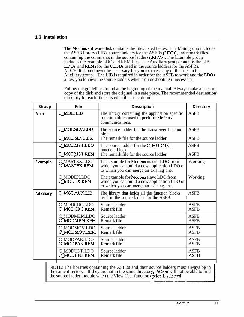
The Modbus software disk contains the files listed below. The Main group includesthe ASFB library (LIB), source ladders for the ASFBs (LDOs), and remark filescontaining the comments in the source ladders (REMs). The Example groupincludes the example LDO and REM files. The Auxiliary group contains the LIB,LDOs, and REMs for the UDFBs used in the source ladders for the ASFBs.NOTE: It should never be necessary for you to access any of the files in theAuxiliary group. The LIB is required in order for the ASFB to work and the LDOsallow you to view the source ladders when troubleshooting if necessary.
Follow the guidelines found at the beginning of the manual. Always make a back upcopy of the disk and store the original in a safe place. The recommended destination’directory for each file is listed in the last column.
Group
Main
Zxample
4uxiliary
File
C-MOD.LIB
C-MODSLV.LDO
C-MODSLVREM
C-MODMST.LDO
C-MODMSTREM
C MASTEX.LDOCIMASTEXREM
C MODEX.LDOC:MODEX.REM
C-MODAUX.LIB
C MODCRC.LDOC:MODCRC.REM
C MODMEM.LDOCIMODMEMREM
C MODMOV.LDOC:MODMOV.REMC MODPAK.LDOCIMODPAKREM
C MODUNP.LDOC:MODUNP.P&M
Description Directory
The library containing the application specific ASFBfunction block used to perform Modbuscommunications.
The source ladder for the transceiver function ASFBblock.The remark file for the source ladder ASFB
The source ladder for the C-MODMSTfunction block.
~ ASFB
The remark file for the source ladder ASFB
The example for Modbus master LDO fromwhich you can build a new application LDO orto which you can merge an existing one.The example for Modbus slave LDO fromwhich you can build a new application LDO orto which you can merge an existing one.
Working
Working
The library that holds all the function blocksIASFB
used in the source ladder for the ASFB.
Source ladderRemark file
Source ladderRemark file
Source ladderRemark file
Source ladderRemark file
Source ladderRemark file
ASFBASFB
ASFBASFB
ASFBASFB
ASFBASFB
ASFBASFB
NOTE: The libraries containing the ASFBs and their source ladders must always be inthe same directory. If they are not in the same directory, PiCPro will not be able to findthe source ladder module when the View User function
Modbus 11

1.4 Modbus Function Blocks
The function block for the Modbus interface is described in this section. WhenPiCFro is running, you can find the Modbus function blocks by choosing theFunction menu, then USER, then C-MOD as shown in Figure 2.
Figure 2. Location of ASFBs in PiCPro
Wires ContactsKoils Functions Data Jumps Horizontal Vertical Longname. l......
ArithBinaryCountersDatatypep$;;'eIOMotion
C-MODMST-
ix EN Ok
The C-MOD librarycontains the ASFB
C-MODSLV-
EN 01
ADDR FAIL
PORT ERF
CFG RCM[
BOOL
BSIZ
DATA
DSIZ
EXPT
R
ASCI
-PORT FAIL
-CFG ERF
- BOOL COMF
-BSIZ TERF
-DATA CODE
-DSIZ
-EXPT
-ASCI
-SEND
-ADDR
- FUNC
-CNT
-LNDX
-RNDX
-BROD
GO@34593
12 Modbus
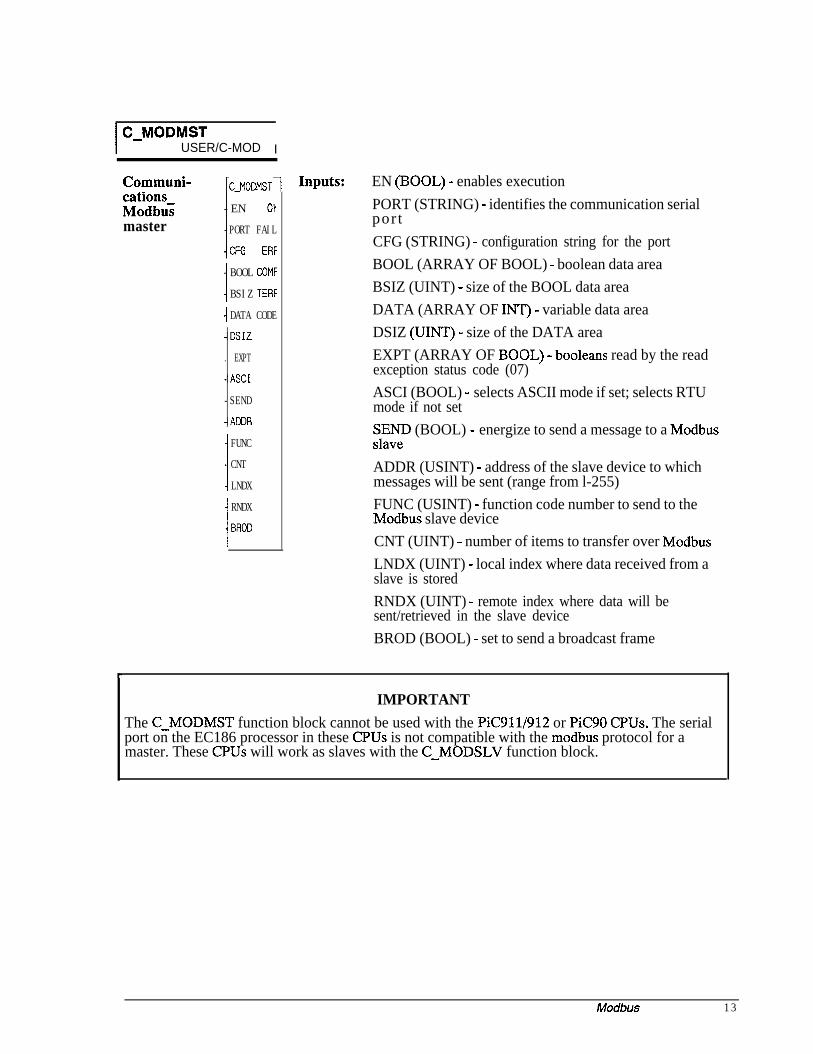
I C-MODMSTUSER/C-MOD I
Communi- ~C-MOM*~ST~ InPuts: EN (BOOL) - enables executioncations-Modbusmaster
-EN 01
-PORT FAIL
-CFG ERF
BOOL COMF
BSIZ TERF
-I DATA CODE-DSIZ
. EXPT
-ASCI
-SEND
-ADDR
! FUNCCNT
LNDX
RNDX
BROD
PORT (STRING) - identifies the communication serialpor tCFG (STRING) - configuration string for the portBOOL (ARRAY OF BOOL) - boolean data areaBSIZ (UINT) - size of the BOOL data areaDATA (ARRAY OF INT) - variable data areaDSIZ (UINT) - size of the DATA areaEXPT (ARRAY OF BOOL) - booleans read by the readexception status code (07)ASCI (BOOL) - selects ASCII mode if set; selects RTUmode if not setSEyeD (BOOL) - energize to send a message to a Modbus
ADDR (USINT) - address of the slave device to whichmessages will be sent (range from l-255)FUNC (USINT) - function code number to send to theModbus slave deviceCNT (UINT) - number of items to transfer over ModbusLNDX (UINT) - local index where data received from aslave is storedRNDX (UINT) - remote index where data will besent/retrieved in the slave deviceBROD (BOOL) - set to send a broadcast frame
IMPORTANTThe C-MODMST function block cannot be used with the PiC911/912 or PiC90 CPUs. The serialport on the EC186 processor in these CPUs is not compatible with the modbus protocol for amaster. These CPUs will work as slaves with the C-MODSLV function block.
Modbus 13

Outputs: OK (BOOL) - execution completed without errorFAIL (BOOL) - initialization failedERR (INT) - 0 if initialization is successful; # 0if initialization is unsuccessfulRCMD (BOOL) - energized if a message is receivedCOMP (BOOL) - energized when a transfer is completeTERR (BOOL) - an error occurred in the transactionCODE (INT) - number of error codecode number 400 = error returned from a slave devicevia an exception responsecode number > 99 = local error
NOTE: C-MODMST function block cannot be used with the C-MODSLV functionblock on the same serial port.The C-MODMST function block provides PiC900 communication capabilities on aModbus network with the PiC900 acting as a Modbus master. The link to thenetwork must be made through one of the PiC900 serial ports.When this function is enabled, it will open the PiC900 serial port specified at thePORT input. This port will be configured based on the information specified at theCFG input. If the port configures properly, the OK output will energize and thesystem will be ready to generate requests as the Modbus master. If a problem occursin the open or configuration process, the FAIL output will be energized and the OKwill not be set. See Appendix B in the PiC900 software manual for the error codesat the ERR output.To establish communications on the Modbus network, this function block is neededonly once and should be enabled every scan.
14 Modbus

Inputs
EN The EN input is energized every scan to respond to a query over the Modbusnetwork.rail.
In a typical system, this input will be wired to the vertical or power bus
PORT
NOTE: De-energizing this input will cause communication to stop.The PORT input specifies which serial port this function block will use tocommunicate over. Place a string type variable at this input that has been initializedwith the name of the port that is to be used.For example, if the PiC900 User port 2 is being used, initialize a string as:
USER:$OOIf one of the channels on the serial communications module is being used, thevariable you enter at the NAMZ input of the ASSIGN function block is the variableyou enter at the PORT input of the C-MODMST function block.
MlW-3991
CFG The string variable at the CFG input holds the initialized configuration string youwill use.If the RTU mode is chosen (see ASCI input), then the configuration string wouldtypically be:
9600, E, 8, 1, N, $00
The port will be set up at 9600 baud, even parity, 8 data bits, no handshaking. Seethe OPEN function block description in the PiC900 Software Manual for moreinformation about this configuration string.If the ASCII mode is chosen (see ASCI input), then the configuration string wouldtypically be :
9600, E, 7,2, N, $00
Modbus 15

BOOL The BOOL input is an array that specifies the boolean (bit) data area that is used forany boolean (bit) transfers. Queries to a slave device for data items 00001 to 09999are placed here.For example, if the array of boolean variables is called BOOL and a write request ismade from register 00222, the PiC900 would send the data in BOOL(221).The array size can range from 2 (O..l)to 999 (0..998) booleans.
IMPORTANTDo not use a positive or negative transistional contact in your LDO with the BOOL array.
If it is necessary to set up a transistional contact with a BOOL array, use the BOOL array toenergize another boolean coil. Then use this boolean for the transistional contact as shown in theexample below.
BOOL(X) BOOL-X
0
BOOL-X
P------
BOOL-X
N ___-_--
BSIT,
DATA
.
DSli?
EXPT
Enter the number of booleans (up to 999).*It is very important that the value in BSIZ and the size of the array in BOOL are thesame. The size is user adjustable from 2 to 999 elements.The DATA input is used to specify the name of the main data area. Queries to aslave device for data items 40001 to 49999 are placed here.For example, if the array of integer variables is called DAT and a read request ismade for register 40005, the PiC900 would place the data it received in response inDAT(4).This data area is an array of integers.Enter the number of integers (up to 999).
*It is very important that the value in DSIZ and the size of the array in DATA are thesame. The size is user adjustable from 2 to 999 elements.The EXPT input is an array of eight booleans. If the PiC900 asks a remote stationfor the exception status (function 7), its response will be placed in this array. Thebits in this array have no special meaning in the PiC900. But they have specialmeaning in a Modicon Control and are provided here to allow the PiC900 to readthem.
16 Modbus

ASCI Controllers can be setup to communicate on Modbus networks using either of twotransmission modes: ASCII or RTU. You select the desired mode at this ASCIinput. If ASCI input is set, then the ASCII mode is in effect. If it is not set, then theRTU mode is in effect. More information on these two modes can be found in yourModbus manual.NOTE: The mode and serial parameters must be the same for all devices on thenetwork. The modes define the bit contents of message fields transmitted serially onthe network. They determine how information will be packed into the messagefields and decoded.
The ASCII Mode
When controllers are setup to communicate on a network using ASCII mode, each 8-bit byte in a message is sent as two ASCII characters.
The format for each byte in the ASCII mode is:
Coding System Hexadecimal, ASCII characters O-9, A-FOne hexadecimal character contained in eachASCII character of the message
Bits per Byte 1 start bit7 data bits, least significant bit sent first1 bit for even/odd parity; no bit for no parity1 stop bit if parity is used; 2 bits if no parity
Error Check Field Longitudinal Redundancy Check (LRC)
In the ASCII mode, the message frame starts with a ‘colon’ (:) character (ASCII 3Ahex) and ends with a ‘carriage return - line feed’ (CRLF) pair (ASCII OD and OA).
The allowable characters transmitted for all other fields are hexadecimal O-9, A-F.Networked devices monitor the network bus continuously for the ‘colon’ character.When one is received, each device decodes the next field (the address field) to findout if it is the addressed device.
Intervals of up to one second can elapse between characters within the message. If agreater interval occurs, the receiving device assumes an error has occurred. A typicalmessage frame is shown below.
Start Address
1 character 2 characters
Function
2 characters
Data
iz characters
LRC check
2 characters
End2 characters
CRLF
Modbus 17

The RTU Mode
When controllers are setup to communicate on a network using RTU mode, each 8-bit byte in a message contains two 4-bit hexadecimal characters. The main advantageof this mode is that its greater character density allows better data throughput thanASCII for the same baud rate. Each message must be transmitted in a continuousstream.
The format for each byte in RTU mode is:
Coding System: Hexadecimal, ASCII characters O-9, A-FOne hexadecimal character contained in eachASCII character of the message
Bits per Byte: 1 start bit8 data bits, least significant bit sent first1 bit for even/odd parity; no bit for no parity1 stop bit if parity is used; 2 bits if no parity
Error Check Field: Cyclical Redundancy Check (CR.C-16)
In the RTU mode, the message frame starts with a silent interval of at least 3.5character times. The first field then transmitted is the device address.
The allowable characters transmitted for all fields are hexadecimal O-9, A-F.Networked devices monitor the network bus continuously including during the silentintervals. When the first field is received, each device decodes it to find out if it isthe addressed device.
Following the last transmitted character, a similar interval of at least 3.5 charactertimes marks the end of the message. A new message can begin after this interval.
The entire message frame must be transmitted as a continuous stream. If a silentinterval of more than 1.5 character times occurs before completion of the frame, thereceiving device flushes the incomplete message and assumes that the next byte willbe the address field of a new message.
Similarly, if a new message begins earlier that 3.5 character times following aprevious message, the receiving device will consider it a continuation of the previousmessage. This will set an error, as the value in the final CRC field will not be validfor the combined messages. A typical message frame is shown below.
Start AddressTl-T2-T3-T4 8 bits
Function8 bits
Datan * 8 bits
LRC check End16 bits Tl-T2-T3-T4
18 Modbus

SEND The SEND input must be energized each time a message is sent to one of theModbus s l a v e s .
ADDR The ADDR input specifies the address of the slave device to which messages will besent.
FUNC
The range of numbers that this input will accept is 1 to 255 (decimal).The FUNC input holds the Modbus function code. The function code numbershown in the table below is sent to the Modbus slave device.
FunctionCode
01
02
03
04
05
Name of functionRead Coil Status
Read Input Status
Read Holding Registers
Read Input Registers
Force Single Coil
06 Preset Single Register
07 Read Exception Status
15 Force Multiple Coils
16 Preset MultipleRegisters
DescriptionReads the ON/OFF status of discrete outputsin the slave.Reads the status of the physical inputs (Inputs10000 to 19999).Reads the binary contents of holding registersin the slave.Reads one or more physical input registers(Inputs 20000 to 29999).Forces a single coil to either ON or OFF.When broadcast, the command forces thesame coil reference in all attached slaves.Presets a value into a single holding register.When broadcast, the command presets thesame register reference in all attached slaves.Reads the contents of eight Exception Statuscoils within the slave. These eight coils areuser-defined.Forces each coil in a sequence of coils toeither ON or OFF. When broadcast, thefunction forces the same coil references in allattached slaves.Presets values into a sequence of holdingregisters. When broadcast, the functionpresets the same register references in allattached slaves.
CNB
LNDX
RNDX
BROD
The CNT input is the number of items to transfer over the Modbus.The LNDX input is the local index. It is the location in this control where datareceived/sent from a slave device will be stored/retrieved.The RNDX input is the remote index. It is the location in the slave device wheredata will be sent/retrieved.The BROD input is set by you when a broadcast type frame is sent.
Modbus 19
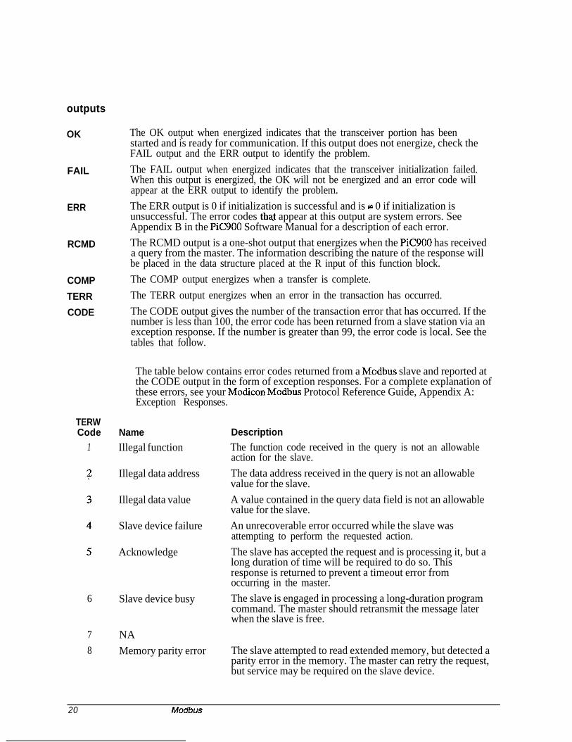
outputs
OK
FAIL
ERR
RCMD
COMP
TERR
CODE
The OK output when energized indicates that the transceiver portion has beenstarted and is ready for communication. If this output does not energize, check theFAIL output and the ERR output to identify the problem.The FAIL output when energized indicates that the transceiver initialization failed.When this output is energized, the OK will not be energized and an error code willappear at the ERR output to identify the problem.The ERR output is 0 if initialization is successful and is z 0 if initialization isunsuccessful. The error codes that appear at this output are system errors. SeeAppendix B in the PiC900 Software Manual for a description of each error.The RCMD output is a one-shot output that energizes when the PiC900 has receiveda query from the master. The information describing the nature of the response willbe placed in the data structure placed at the R input of this function block.The COMP output energizes when a transfer is complete.The TERR output energizes when an error in the transaction has occurred.The CODE output gives the number of the transaction error that has occurred. If thenumber is less than 100, the error code has been returned from a slave station via anexception response. If the number is greater than 99, the error code is local. See thetables that follow.
The table below contains error codes returned from a Modbus slave and reported atthe CODE output in the form of exception responses. For a complete explanation ofthese errors, see your Modicon Modbus Protocol Reference Guide, Appendix A:Exception Responses.
TERWCode
1NameIllegal function
Illegal data address
Illegal data value
Slave device failure
Acknowledge
6 Slave device busy
7 NA8 Memory parity error
DescriptionThe function code received in the query is not an allowableaction for the slave.The data address received in the query is not an allowablevalue for the slave.A value contained in the query data field is not an allowablevalue for the slave.An unrecoverable error occurred while the slave wasattempting to perform the requested action.The slave has accepted the request and is processing it, but along duration of time will be required to do so. Thisresponse is returned to prevent a timeout error fromoccurring in the master.The slave is engaged in processing a long-duration programcommand. The master should retransmit the message laterwhen the slave is free.
The slave attempted to read extended memory, but detected aparity error in the memory. The master can retry the request,but service may be required on the slave device.
20 Modbus

TERRCode100101
102
103
104
105 Invalid function
106 Broadcast error
107
108
109
110
The table below contains the error codes that are detected locally the PiC900 andreported at the CODE output.
NameCRC errorAddress error
Function error
Time-out error
Invalid function
Boolean array size error
Integer array size error
LNDX value error
LNDX value error
DescriptionThe message,from the slave device has failed CRC.The message from the slave device has an unexpected valuein the address field.The message from the slave device has an unexpected valuein the function field.No response message has been received for the slave devicewith 350 ms.The value at the FUNC input is invalid. No functions abovefunction 16 are currently supported.The value at the FUNC input is invalid. The functionnumber is not supported.The function requested will not support broadcast mode asdefined by Modbus.The amount of data requested would overflow the booleandata array defined by the user.The amount of data requested would overflow the integerdata array defined by the user.The offset of data requested would overflow the booleandata array defined by the user. In other words, the locationof the data is too close to the end of the array, given theamount of data being transferred.The amount of data requested would overflow the integerdata array defined by the user.
Modbus Master
As a Modbus master, the PiC900 will query a remote device for integer and booleandata. The C-MODMST function block described above is entered in yourapplication program one time. It is responsible for all communications to and fromthe PiC900 for Modbus support. Enable it every scan. Each input must have theappropriate variable attached to it.
All data being sent to or retrieved from the PiC900 will have a function code numberassociated with it. Although this number has no direct equivalent in the PiC900, it isused to determine where to place or retrieve data.
All functions that read registors from a remote device will have their response dataplaced in the integer array specified at the DATA input. All functions that readbooleans from a remote device will have their response data placed in the booleanarray specified at the BOOL input.
Modbus 21

Modbus master example LDO
The example LDO called C-MASTEX.LDO is included with the software files youreceived. If you are creating a new application ladder, open the C-MASTEX.LDOand use the save AS command to name it whatever your application will be called.
If you want to add the C-MASTEX.LDO to an existing application ladder, you canuse the optional LDOMERGE software to combine them.
Both of these methods produce an application ladder with the software declarationsfor the C MODMST function block already entered. You can modify this to fit yourapplicat&.
You can also insert the C-MODMST function block into an existing ladder and enterthe software declarations yourself.
Workstation Processor Module Declarations Network Element View
t his’i;nciibn enables the PiC900 to be a Modbus Master over an RS232connect ion.It is configured as: Station 1
RTU mode at 9600 baud, Even Parit8
8 data bits, 1 stop bit100 booleans have been defined (U iI7 ADJUSTABLE)100 integers have been defined (USER ADJUSTABLE)
This function will OPEN and CONFIGURE the serial port specified at the PORTinput on the rising edge of the EN00 input. This input should be enabled allthe time, or as long as communication is required (typically all the time).
22 Modbus

HOW TO START A TRANSACTION WITH A SLAVE STATION:___-_____c--------------------------------------------------------------------Each time the SENDMSG contact transition from off to on the C-MODMST functionwill use the data at the function’s inputs to build a frame to be sent to aslave station. Once sent it will wait up to 350 milliseconds for a response.During this time period, no additional requests will be processed. Once theresponse data has been received and decoded the COMP output will be energizedto indicate that the transaction is complete. If a problem occurs during thetransaction, and the transfer fails, the FAIL output will be energized andan error code will appear at the ERR output to indicate what the problem is.
NOTE: If this Modbus Master ASFB is going to be used over the USER port on theCPU module and the port needs to be configured for any setup other than8 data bits, No parity, 1 Stop bit, it will be necessary to have version11 or higher system eproms in the CPU. If the Serial Communications
Moduleis being used this is not necessary.
100 DSIZ-I
:ind'bi'Module>
MOD-ERRTRANCOMP-w-+TRANSERR---(Sk---/
-ERRCODE
Modbus 23
MOD-OK;;;B&
EXCEPTSENDMSGDESTADDRFUNCTION
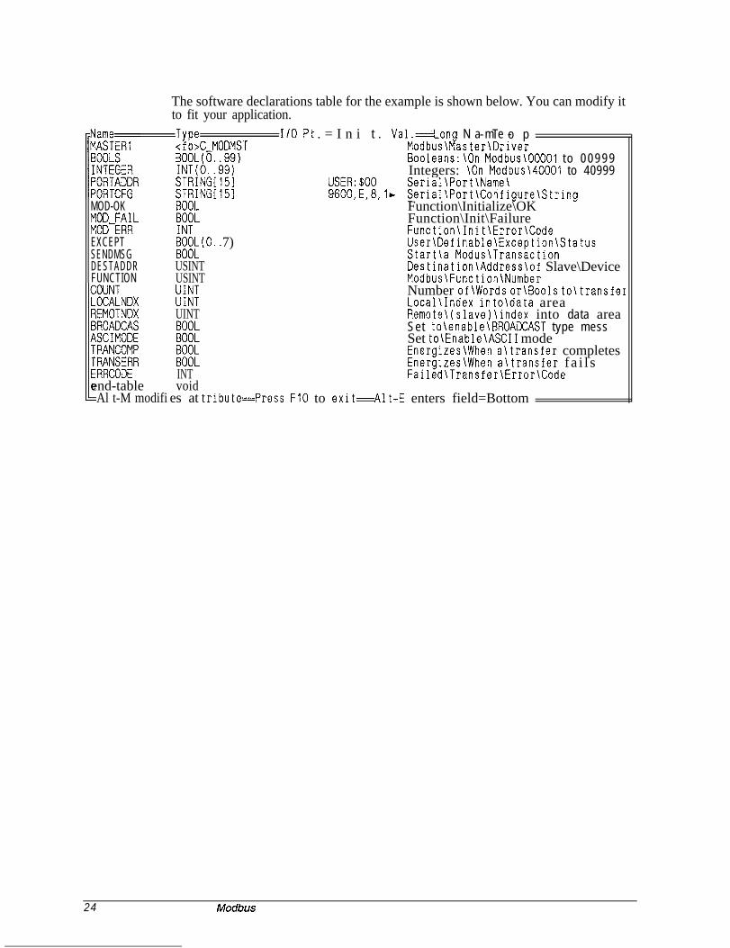
The software declarations table for the example is shown below. You can modify itto fit your application.
Type I/O Pt<fb>C-MODMST
. = I n i t . Val.=Long N a m e -- T o pModbus\Master\Driver
BOOL(O..99) Booleans:\On Modbus\OOOOl to 00999INT(0. .99)STRIN$l51 USER:$OO
Integers: \On Modbus\ to 40999Serial\Port\Name\
Sg;TR;Nlrr[l51
iFLm&(0.. 7)
USINTUSINT
iii:UINT
E
Ei:INTvoid
es at trIIend-tableAl t-M modifi
9600,E,8,1, Serial\Port\Configure\StringFunction\Initialize\OKFunction\Init\FailureFunction\Init\Error\CodeUser\Definable\Exception\StatusStart\a Modus\TransactionDestination\Address\of Slave\DeviceModbus\Function\NumberNumber of\Words or\Bools to\transferLocal\Index into\data areaRemote\(slave)\index into data areaSet to\enable\BROACCAST type messSet to\Enable\ASCII modeEnergizes\When a\transfer completesEnergizes\When a\transfer f a i l sFailed\Transfer\Error\Code
ibute=Press FlO to exit=Alt-E enters field=Bottom
24 Modbus

C-MODMST function block setup
The steps for setting up the C-MODMST function block allowing the PiC900 tofunction as a Modbus master follows.
1.2.
3.
4.5.
6.
7.
8.
9.10.
Determine the address for the slave device and enter it at the ADDR input.Determine which serial port is going to be used for the Modbuscommunications. If the USER port is going to be used, initialize a string typevariable as follows:PORTADDR STRING(lO) “USER:$OO”Determine the proper communications configuration for the serial port. Thenassign a string type variable an Initial Value that when placed at thePORTCFG input will configure the communications channel. See the CFGZinput on the CONFIG function in the PiC900 Software Manual for moreinformation on the configuration string.
ASCII Example: For 9600 baud, Even parity, 7 data bits, 1 stop bit,CONFIG STRING(15) “9600,E,7,2,N,$OO”
RTU Example: For 19200 baud, Even parity, 8 data bits, 2 stop bitCONFIG STRING( 15) “l92OO,E,S,l,N,$OO”
Determine how many booleans (bit type) will be needed for your application.Modify the size of the BOOLS array in the software declaration table bysetting it to the size determined in step 4. In the software declarations table,place the cursor on the data item named BOOLS and press <Ah> A to enterthe array length. The acceptable range is from 2 to 999.The size of the boolean array (BOOLS) must be entered in BSIZ(booleansize).Determine how many integers will be needed for your application. Theacceptable range is from 1 to 999.Modify the size of the INTEGER array in the software declaration table bysetting it to the size determined in step 7. In the software declarations table,place the cursor on the data item named INTEGER and press <Ah> A to enterthe array length.The size of the integer array (INTEGER) must be entered in DSIZ (data size).Determine whether ASCII or RTU mode will be used and set the ASCI inputaccordingly.
Modbus 25

Communi-cations
C-MODSLV-
Modbui !EN OK
slave -ADDR FAIL
-PORT ERR
-CFG RCMC
- BOOL
-BSIZ
-DATA
- DSIZ
-EXPTRASCI
I-
I-
Inputs: EN (BOOL) - enables executionADDR (USINT) - address for the PiC900 (range froml-255)PORT (STRING) - identifies the communication serialPO*CFG (STRING) - configuration string for the portBOOL (ARRAY OF BOOL) - boolean data areaBSIZ (UINT) - size of the BOOL data areaDATA (ARRAY OF INT) - variable data areaDSIZ (UINT) - size of the DATA areaEXPT (ARRAY OF BOOL) .- booleans read by the readexception status code (07)R (STRUCT) - message information including addressand function codeASCI (BOOL) - selects ASCII mode if set; selects RTUmode if not set
outputs: OK (BOOL) - execution completed without errorFAIL (BOOL) - initialization failedERR (INT) - 0 if initialization is successful; f 0if initialization is unsuccessfulRCMD (BOOL) - energized if a message is received
The C-MODSLV function block provides PiC900 communication capabilities on aModbus network. The link to the network must be made through one of the PiC900serial ports.When this function is enabled, it will open the PiC900 serial port specified at thePORT input. This port will be configured based on the information specified at theCFG input. If the port configures properly, the OK output will energize and thesystem will be ready to respond to queries from the Modbus master. If a problemoccurs in the open or configuration process, the FAIL output will be energized andthe OK will not be set. See Appendix B in the PiC900 software manual for the errorcodes at the ERR output.To establish communications on the Modbus network, this function block is neededonly once and should be enabled every scan.
26 Modbus

Inputs
EN The EN input is energized every scan to respond to a query over the Modbusnetwork.rail.
In a typical system, this input will be wired to the vertical or power bus
ADDR
PORT
NOTE: De-energizing this input will cause communication to stop.The ADDR input specifies the address this PiC900 will be on the network. Thisinput must have a unique number which represents the PiC900 address.The range of numbers that this input will accept is 1 to 255 (decimal).-The PORT input specifies which serial port this function block will use tocommunicate over. Place a string type variable at this input that has been initializedwith the name of the port that is to be used.For example, if the PiC900 User port 2 is being used, initialize a string as:
USER: $00If one of the channels on the serial communications module is being used, thevariable you enter at the NAMZ input of the ASSIGN function block is the variableyou enter at the PORT input of the C-MODSLV function block.
NAME
ASSIGN
EN OK
COMN FAIL
/
NAMZ ERR
RACK
SLOT
CHANAA1044-3991
CFG The string variable at the CFG input holds the initialized configuration string youwill use.If the ASCII mode is chosen (see ASCI input), then the configuration string wouldtypically be :
9600, E, 7,2, N, $00If the RTU mode is chosen (see ASCI input), then the configuration string wouldtypically be:
9600, E, 8, 1, N, $00
.-
Modbus 27

BOOL The BOOL input is an array that specifies the boolean (bit) data area that is used forany boolean (bit) transfers. Queries from the master device for data items 00001 to00999 are found here.For example, if the array of booleans variable is called BOOL and a query is madefor register 00222, the PiC900 would respond with the data in BOOL(221).The array size can range from 2 (O..l)to 999 (0..998) booleans.
IMPORTANTDo not use a positive or negative transistional contact in your LDO with the BOOL array. I
If it is necessary to set up a transistional contact with a BOOL array, use the BOOL array toenergize another boolean coil. Then use this boolean for the transistional contact as shown in theexample below.
BOOL(X) BOOL-X___-
o-
BOOL-X
BOOL-X
BSIT*
DATA
Enter the number of booleans (up to 999).*It is very important that the value in size in BSIZ and the size of the array in BOOLare the same. The size is user adjustable from 2 to 999 elements.The DATA input is used to specify the name of the main data area. Queries fromthe master device for data items 40001 to 40999 are found here.
DSIT*
EXPT
R
For example, if the array of integers variable is called DAT and a query is made forregister 40005, the PiC900 would respond with the data in DAT(4).This data area is an array of integers.Enter the number of integers (up to 999).
*It is very important that the value in size in DSIZ and the size of the array in DATAare the same. The size is user adjustable from 2 to 999 elements.When the read exception status command is issued by the master device, the valuesin this boolean array are returned. The booleans are user-defined.The R structure specifies a data area that information about the last query is placed.When a query is received, Modbus function data is placed in the data area specifiedby this input. The structure placed at this input must have the format shown below.
28 Modbus

Declared array of structures for R input
ASCI
R STRUCT.ADDRESS.FUNCTION Ed:
END-STRUCT
The function codes for the Modbus functions are as follows.
FunctionCode
01Name of functionRead Coil Status
03
05
Read Holding Registers
Force Single Coil
06 Preset Single Register
07 Read Exception Status
15 Force Multiple Coils
16 Preset MultipleRegisters
DescriptionReads the ON/OFF status of discrete outputsin the slave.Reads the binary contents of holding registersin the slave.Forces a single coil to either ON or OFF.When broadcast, the command forces the samecoil reference in all attached slaves.Presets a value into a single holding register.When broadcast, the command presets thesame register reference in all attached slaves.Reads the contents of eight Exception Statuscoils within the slave. These eight coils areuser-defined. .Forces each coil in a sequence of coils toeither ON or OFF. When broadcast, thefunction forces the same coil references in allattached slaves.Presets values into a sequence of holdingregisters. When broadcast, the functionpresets the same register references in allattached slaves.
Controllers can be setup to communicate on Modbus networks using either of twotransmission modes: ASCII or RTU. You select the desired mode at this ASCIinput. If ASCI input is set, then the ASCII mode is in effect. If it is not set, then theRTU mode is in effect.Modbus manual.
More information on these two modes can be found in your
NOTE: The mode and serial parameters must be the same for all devices on thenetwork. The modes define the bit contents of message fields transmitted serially onthe network. They determine how information will be packed into the messagefields and decoded.
The ASCII Mode
When controllers are setup to communicate on a network using ASCII mode, each 8-bit byte in a message is sent as two ASCII characters.
The format for each byte in the ASCII mode is:
Modbus 29

Coding System Hexadecimal, ASCII characters O-9, A-FOne hexadecimal character contained in eachASCII character of the message
Bits per Byte 1 start bit7 data bits, least significant bit sent first1 bit for even/odd parity; no bit for no parity1 stop bit if parity is used; 2 bits if no parity
Error Check Field Longitudinal Redundancy Check (LRC)
In the ASCII mode, the message frame starts with a ‘colon’ (:) character (ASCII 3Ahex) and ends with a ‘carriage return - line feed’ (CRLF) pair (ASCII OD and OA).
The allowable characters transmitted for all other fields are hexadecimal O-9, A-F.Networked devices monitor the network bus continuously for the ‘colon’ character.When one is received, each device decodes the next field (the address field) to findout if it is the addressed device.
Intervals of up to one second can elapse between characters within the message. If agreater interval occurs, the receiving device assumes an error has occurred. A typicalmessage frame is shown below.
Start Address Function Data LRC check End
1 character 2 characters 2 characters n characters 2 characters2 characters
CRLF
NOTE: The data field cannot exceed 128 bytes in length.
The RTU Mode
When controllers are setup to communicate on a network using RTU mode, each 8-bit byte in a message contains two 4-bit hexadecimal characters. The main advantageof this mode is that its greater character density allows better data throughput thanASCII for the same baud rate. Each message must be transmitted in a continuousstream.
The format for each byte in RTU mode is:
Coding System: Hexadecimal, ASCII characters O-9, A-FOne hexadecimal character contained in eachASCII character of the message
Bits per Byte: 1 start bit8 data bits, least significant bit sent first1 bit for even/odd parity; no bit for no parity1 stop bit if parity is used; 2 bits if no parity
Error Check Field: Cyclical Redundancy Check (CRC-16)
In the RTU mode, the message frame starts with a silent interval of at least 3.5character times. The first field then transmitted is the device address.
The allowable characters transmitted for all fields are hexadecimal O-9, A-F.Networked devices monitor the network bus continuously including during the silentintervals. When the first field is received, each device decodes it to find out if it isthe addressed device.
30 Modbus

Following the last transmitted character, a similar interval of at least 3.5 charactertimes marks the end of the message. a new message can begin after this interval.
The entire message frame must be transmitted as a continuous stream. If a silentinterval of more than 1.5 character times occurs before completion of the frame, thereceiving device flushes the incomplete message and assumes that the next byte willbe the address field of a new message.
Similarly, if a new message begins earlier that 3.5 character times following aprevious message, the receiving device will consider it a continuation of the previousmessage. This will set an error, as the value in the final CRC field will not be validfor the combined messages. Atypical message frame is shown below.
Start AddressTl-T2-T3-T4 8 bits
Functidn8 bits
Datan * 8 bits
LRC check End16 bits Tl-T2-T3-T4
NOTE: The data field cannot exceed 128 bytes in length.
outputs
OK
FAIL
ERR
RCMD
The OK output when energized indicates that the transceiver portion has beenstarted and is ready for communication. If this output does not energize, check theFAIL output and the ERR output to identify the problem.The FAIL output when energized indicates that the transceiver initialization failed.When this output is energized, the OK will not be energized and an error code willappear at the ERR output to identify the problem.The ERR output is 0 if initialization is successful and is # 0 if initialization isunsuccessful. The error codes that appear at this output are system errors. SeeAppendix B in the PiC900 Software Manual for a description of each error.The RCMD output is a one-shot output that energizes when the PiC900 has receiveda query from the master. The information describing the nature of the query will beplaced in the data structure placed at the R input of this function block.
Modbus Slave
As a Modbus slave, the PiC900 will receive and respond to Modbus functions fromother devices but will not initiate any transfers. The C-MODSLV function blockdescribed above is entered in your application program one time. It is responsible forall communications to and from the PiC900 for Modbus support. Enable it everyscan. Each input must have the appropriate variable attached to it.
All data being sent to or retrieved from the PiC900 will have a code numberassociated with it. Although this number has no direct equivalent in the PiC900, it isused to determine where to place or retrieve data.
The PiC900 will only respond to requests directed at one of the function codes itsupports. Requests made to any other function codes will generate an error responseto the device that made the request.
Modbus 31

Mqdbus slave example LDO
The example LDO called C-MODEX.LDO is included with the software files youreceived. If you are creating a new application ladder, open the C-MODEX.LDOand use the save AS command to name it whatever your applicatron will be called.
If you want to add the C-MODEX.LDO to an existing application ladder, you canuse the optional LDOMERGE software to combine them.
Both of these methods produce an application ladder with the software declarationsfor the C MODSLV function block already entered. You can modify this to fit yourapplicati6.r.
You can also insert the C-MODSLV function block into an existing ladder and enterthe software declarations yourself.
C-MODEX.LDO
Workstation Processor Module Declarations Network Element ViewCommynt Editor: Insert Mode Line: 1 of 19 Col: 1
t his function enables the PiC900 to be a Modbus Slave over an RS232 connection.It is configured as: Station 1
RTU mode at 9600 baud, Even Parity, 8 data bits, 1 stop bit,No hardware handshaking800 booleans have been defined (USER ADJUSTABLE)400 integers have been defined (USER ADJUSTABLE)
Over Modbus the’Integer array maps into register: 40001 to 40400 and the Booleanarray is accessed over Modbus with bit numbers: 00001 to 00800. Any requestsfor data to/from Ixxxx, ~XXXX, or 3xxxx will cause an error response to bereturned from the PiC900 Modbus Slave.
NOTE: If this Modbus Slave ASFB is going to be used over the USER port on theCPU module and the port needs to be configured for any setup other than8 data b i ts , No parit
4;, 1 Stop bit, it will be necessary to have version
11 or later system EP OMs in the CPU. If the Serial Communications Module,is being used this is not necessary.
32 Modbus
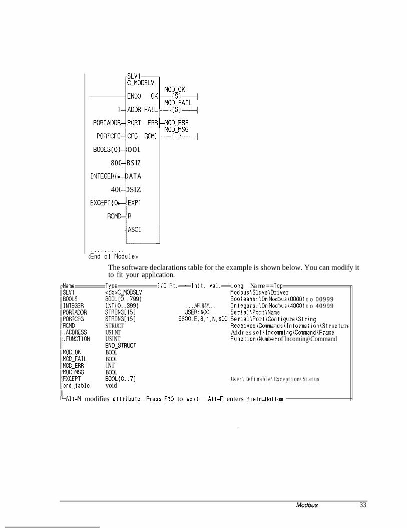
SLVI-C-MODSLV
-IRC!l[
BOOLS(0) BOOL
800 BSIZ
iINTEGER(w DATA
400 DSIZi
:iiAd’bi’Mbdule>
The software declarations table for the example is shown below. You can modify itto fit your application.
FName Type I/O Pt .=Init. Val.=Long Name==Topl/SLVi <f b>C-MODSLV Modbus\Slave\DriverllBOOLS BOOL(O..799) Booleans:\On Modbus\OOOOl to 00999l/INTEGER INT(0..399) .AFiRAY...
USER:$OOIntegers:\On Modbus\ to 40999
IIPORTADDR STRING[151 Serial\Port\NameIIPORTCFG STRINGLISIl]RCMD STRUCT
9600,E,8,l,N,$OO Serial\Port\Configure\StringReceived\Commands\Information\Structurf
II.ADDRESS USINT Address of\Incomming\Command\Framell.FUNCTION USINT Function\Number of Incoming\Command
I/MOD-OKEND-STRUCTBOOL
[IMOD-FAIL BOOLIJMOD-ERR INTI/MOD-MSG BOOLIIEXCEPT BOOL(O..7) User\Definable\Exception\StatusI/end-table voidIIWit-M modifies attribute=Press FIO to exit--Alt-E enters field=Bottom
Modbus 33

C-MODSLV function block setup The steps for setting up the C-MODSLV function blockallowing the PiC900 to function as a Modbus slave follows.
1.2.
Determine the address for the PiC900 and enter it at the ADDR input.Determine which serial port is going to be used for the Modbuscommunications. If the USER port is going to be used, initialize a string typevariable as follows:
3.PORTADDR STRING(lO) “USER: $00”Determine the proper communications configuration for the serial port. Thenassign a string type variable an Initial Value that when placed at thePORTCFG input will configure the communications channel. See the CFGZinput on the CONFIG function in the PiC900 Software Manual for moreinformation on the configuration string.
ASCII Example: For 9600 baud, Even parity, 7 data bits, 1 stop bit,CONFIG STRING(15) “9600 E 7 2 N,$OO”, ,Y,
RTU Example: For 19200 baud, Even parity, 8 data bits, 2 stop bitCONFIG STRING( 15) “192OO,E,S,l,N,$OO”
4.5.
6.
7.
8.
Determine how many booleans (bit type) will be needed for your application.Modify the size of the BOOLS array in the software declaration table bysetting it to the size determined in step 4. In the software declarations table,place the cursor on the data item named BOOLS and press <Ah> A to enterthe array length. The acceptable range is from 2 to 999.The size of the boolean array (BOOLS) must be entered in BSIZ(booleans i z e ) .Determine how many integers will be needed for your application. Theacceptable range is from 1 to 999.Modify the size of the INTEGER array in the software declaration table bysetting it to the size determined in step 7. In the software declarations table,place the cursor on the data item named INTEGER and press <Ah> A to enterthe array length.
9. The size of the integer array (INTEGER) must be entered in DSIZ (data size).10. Determine whether ASCII or RTU mode will be used and set the ASCI input
accordingly.
34 Modbus

Index
AADDR 18,27addressing 9ASCI 1529ASCII mode 16,29ASFBs 1
guidelines 1revising 2, 3using 4
BBOOL 1527BROD 18BSIZ* 15,27
Ccables 8CFG 15, 27CNT 18CODE 19codes
Modbus function 9Modbus master function 18,20,21Modbus slave function 28
COMP 19compatibility 9configurations 5CPUS 13C-MODMST function block 7,13
inputs 14outputs 19
C-MODSLV function block 7, 26inputs 27
. outputs 31
DDATA 15,28directories 11directory 1DSIZ* 15,28
EEN 2,14,27EPROM
version 32ERR 19,31example LDO
master 22slave 32
EXAMPLESdirectory 1
EXPT 15,28
FFAIL 19,31files 11FUNC 18function blocks
location 12function codes
Modbus 9Modbus master 18, 20,21Modbus slave 28
Gguidelines
ASFBs 1
Hhardware requirements 8
Iinstallation 1, 11interface devices 6
Lladder
source 2LDO
master example 22slave example 32
LDO files 1LIB files 1LNDX 18
MModbus 5
function codes 9master example 22master function codes 18,20,21protocol 5, 6slave example 32slave function codes 28
modeASCII 16,29master 21
setup 25RTU 16,30slave 31
setup 34
0OK 19,31
Index i

P SSEND 18software declarations 24,33software requirements 9source ladder 2
pinouts 8PORT 14,27ports 5,8
Q -IQuery 7query response cycle 6
RR 28
structure 28RCMD 19,31Response 7revising ASFBs 2, 3RNDX 18RQ2RTU mode 16,30
TTERR 19transitionals 16,28
Vversion numbers 2
wwiring 8
Ii Index