model 1290 xlt xenon followspot - lycian parts manual.pdf · - 2 - model 1290 xlt xenon followspot...
TRANSCRIPT
Model 1290 XLT Xenon Followspot Table of Contents
CAUTIONS AND WARNINGS…………………………………………………………….. - 1 - 1 SETUP…………………………………………………………………………….. ....- 2 - 2 ELECTRICAL CONNECTION……………………………………………………...- 2 -
2.1 Input requirements……………………………………………………………. ...- 2 - 3 LAMP SPECIFICATIONS………………………………………………………… ..- 2 - 4 LAMPING……………………………………………………………………………..- 3 - 5 DE-LAMPING………………………………………………………………………...- 4 - 6 FIXTURE ILLUMINATION……………………………………………………….. ...- 5 - 7 LAMP OPTICAL ALIGNMENT…………………………………………………… ..- 6 - 8 LAMP LIFE………………………………………………………………………… ...- 6 - 9 COLOR BOOMERANG / COLOR CHANGER………………………………… ...- 6 - 10 GOBO HOLDER…………………………………………………………………......- 6 - 11 EFFECTS DIPSTICK SLOT……………………………………………………… ..- 7 - 12 FIXTURE BALANCING…………………………………………………………… ..- 7 - 13 REPLACEMENT OF TIMER BATTERY…………………………………………..- 7 - APPENDIX A - TROUBLESHOOTING…………………………………………………… - 8 - APPENDIX B - OPTICAL SETUP AND ALIGNMENT SEQUENCE………………..…. - 9 -
Parts Manual FIGURE 1. 1290 XLT FOLLOWSPOT………………………………………………….. - 12 - FIGURE 2. XLT 2K XENON LONG THROW (DETAIL)………………………………..- 14 - FIGURE 3. FRONT LENS ASSEMBLY…………………………………………………. - 16 - FIGURE 4. COLOR BOOM AND COLOR CHANGER ASSEMBLIES………………. - 18 - FIGURE 5. SHUTTER ASSEMBLY………………………………………………………- 20 - FIGURE 6. REAR LENS ASSEMBLY……………………………………………………- 22 - FIGURE 7. BELLY PAN ASSEMBLY…………………………………………………….- 24 - FIGURE 8. FOCUS ASSEMBLY………………………………………………………….- 26 - FIGURE 9. FADER MID PLATE ASSEMBLY………………..………………………….- 28 - FIGURE 10. REAR LAMP ADJUSTMENT ASSEMBLY………………………………. - 30 - FIGURE 11. FADER SHAFT ASSEMBLY……………………………………………….- 32 - FIGURE 12. PULLEY WHEEL ASSEMBLY……………………………………………..- 34 - FIGURE 13. FRONT LAMP HOLDER ASSEMBLY…………………………………….- 36 - FIGURE 14. AIR FLOW SWITCH ASSEMBLY………………………………………… - 38 - FIGURE 15. POWER TRAY ASSEMBLY………………………………………………. - 40 - FIGURE 16. YOKE ASSEMBLY…………………………………………………………. - 42 - FIGURE 17. BASE STEM FOLDING ASSEMBLY…………………………………….. - 44 - FIGURE 18. 1290 HEAD WIRING DIAGRAM…………………………………………..- 46 -

- 1 -
CAUTIONS AND WARNINGS • DO NOT HANDLE THE XENON LAMP WITHOUT PROTECTIVE CLOTHING,
FACE MASK AND GLOVES. • EXPLOSION HAZARD EXISTS AS LAMP IS HIGHLY PRESSURIZED. • OBSERVE ALL HANDLING INSTRUCTIONS PROVIDED BY THE LAMP
MANUFACTURER. • ONLY TRAINED PERSONNEL FAMILIAR WITH HANDLING XENON LAMPS
SHOULD PERFORM LAMPING, UNLAMPING AND GENERAL LAMPHOUSE MAINTENANCE.
• THE LAMP MUST BE CHANGED IF IT HAS BECOME DAMAGED OR
THERMALLY DEFORMED. • SHIELDS, LENSES OR ULTRAVIOLET SCREENS MUST BE CHANGED IF THEY
HAVE BECOME VISIBLY DAMAGED TO SUCH AN EXTENT THAT THEIR EFFECTIVENESS IS IMPAIRED BY CRACKS OR DEEP SCRATCHES.
• DISTANCE FROM THE FIXTURE TO LIGHTED OBJECTS MUST BE GREATER
THAN 15 METERS (50FT) TO AVOID POSSIBLE COMBUSTION. • THE EXTERIOR OF THE FIXTURE MAY REACH TEMPERATURES OF 70
DEGREES CELSIUS OR 158 DEGREES FAHRENHEIT. • KEEP ALL COMBUSTABLE MATERIAL GREATER THAN 1 METER (3.3FT)
FROM THE FIXTURE.
- 2 -
Model 1290 XLT Xenon Followspot Setup, Lamping and Operating Instructions
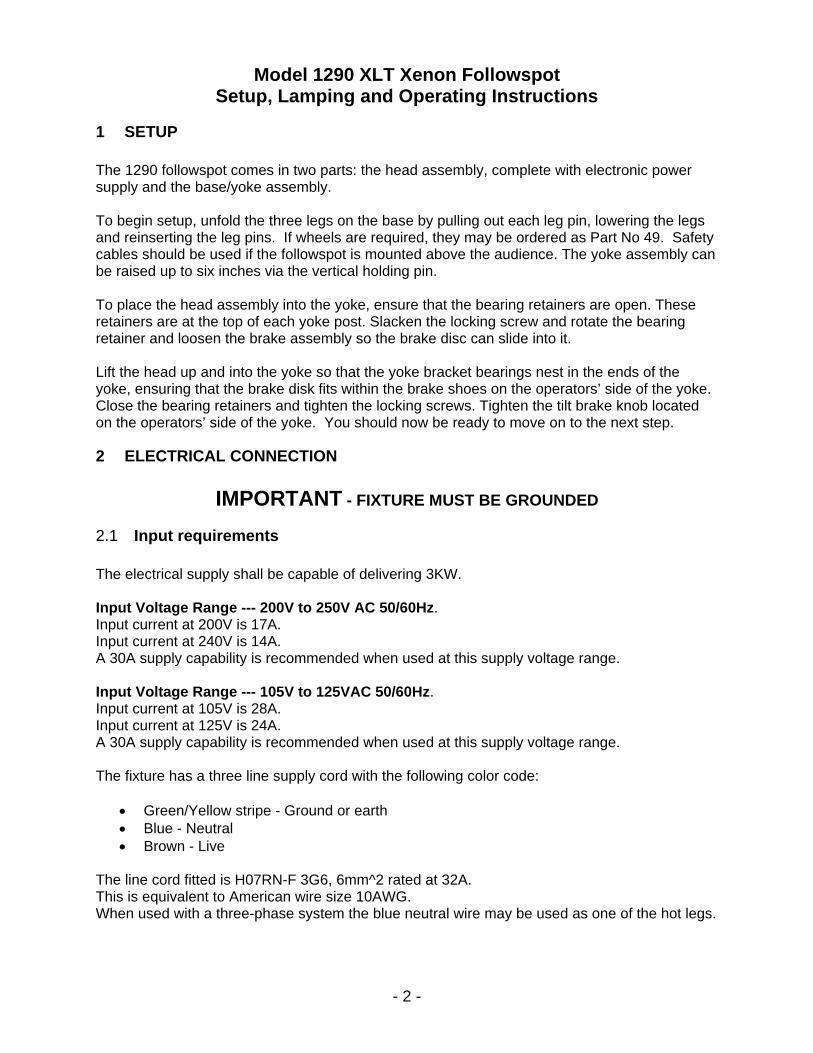
1 SETUP The 1290 followspot comes in two parts: the head assembly, complete with electronic power supply and the base/yoke assembly. To begin setup, unfold the three legs on the base by pulling out each leg pin, lowering the legs and reinserting the leg pins. If wheels are required, they may be ordered as Part No 49. Safety cables should be used if the followspot is mounted above the audience. The yoke assembly can be raised up to six inches via the vertical holding pin. To place the head assembly into the yoke, ensure that the bearing retainers are open. These retainers are at the top of each yoke post. Slacken the locking screw and rotate the bearing retainer and loosen the brake assembly so the brake disc can slide into it. Lift the head up and into the yoke so that the yoke bracket bearings nest in the ends of the yoke, ensuring that the brake disk fits within the brake shoes on the operators’ side of the yoke. Close the bearing retainers and tighten the locking screws. Tighten the tilt brake knob located on the operators’ side of the yoke. You should now be ready to move on to the next step.
2 ELECTRICAL CONNECTION
IMPORTANT - FIXTURE MUST BE GROUNDED
2.1 Input requirements The electrical supply shall be capable of delivering 3KW. Input Voltage Range --- 200V to 250V AC 50/60Hz. Input current at 200V is 17A. Input current at 240V is 14A. A 30A supply capability is recommended when used at this supply voltage range. Input Voltage Range --- 105V to 125VAC 50/60Hz. Input current at 105V is 28A. Input current at 125V is 24A. A 30A supply capability is recommended when used at this supply voltage range. The fixture has a three line supply cord with the following color code:
• Green/Yellow stripe - Ground or earth • Blue - Neutral • Brown - Live
The line cord fitted is H07RN-F 3G6, 6mm^2 rated at 32A. This is equivalent to American wire size 10AWG. When used with a three-phase system the blue neutral wire may be used as one of the hot legs.
- 3 -
3 LAMP SPECIFICATIONS The correct lamp for this fixture is a 2KW short-arc discharge lamp with a xenon gas filled envelope. Typical lamp current is 75 to 80 amps. Please consult lamp manufacturer for recommended lamp current. The anode (+) terminal is 9.5mm diameter with a cable attached for connection to the igniter. The cathode (-) terminal is 8.0mm diameter. The overall length of the lamp is 342mm, with a globe diameter of 60mm. The lamp has a suggested life expectancy of 2000 hours. The lamp light output diminishes with age as the inside of the globe blackens and therefore the lamp should be rotated 90 degrees along its length after 500 hours so that the top blackened area is at another location avoiding blackening in one spot. A new bulb should be run at 85% of its maximum value so when bulb is blackening you increase current to lamp by 2 amps, after rotation, to maintain a constant level of brightness throughout its life. The recommended manufacturers of suitable lamps are:
• Osram XBO 2000 W / HS OFR • Yumex YXL 20SC • Ushio CXL20SC
4 LAMPING
Remove all electrical power from the fixture by turning off the 30A circuit breaker on the power tray or by turning off the wall disconnect switch and make sure that you have your protective gear on. Remove the lamphouse top cover by undoing the six security screws using the special torx wrench (TR25x100) provided with each followspot. On removal of the xenon lamp from its protective container, it is suggested by Lycian to remove the thin assist wire that goes across the lamp globe. If this wire is not removed, it is probable that the ignition voltage (50KVAC) will jump between this wire and the reflector rather than striking across the lamp electrodes inside the globe. Under certain conditions the arc will strike and the wire will vaporize anyway and probably cause slight damage to the reflector. Using a pair of small wire cutters, clip off the very thin assist wire which goes across the globe and attaches to the +ve terminal. Discard this wire and continue with the lamp installation. Tilt the front lamp support forward. Loosen the allen screws on both the front and rear lamp holders. Remove nut and split washer from ”LAMP (+) OUT” terminal on the 932 igniter with a 9/16” wrench.
- 4 -
4 LAMPING (CONT’D.) Standing on the right hand side of the lamphouse, and holding the xenon lamp (+ve) terminal in the left hand, insert the (-ve) terminal through the hole in the rear of the reflector. Bring the front lamp holder up to meet the lamp and insert the terminal into the front lamp holder contact block. Do not tighten the two screws at this time. Insert the (+ve) terminal into the rear lamp holder insulator. Tighten the rear collar screw with a 7/64” allen key when the terminal is fully seated in the (+ve) rear lamp holder. Attach the (+ve) electrode wire to the LAMP (+) OUT 3/8 dia stud on the red igniter. Secure with the 3/8 nut and lock washer. Tighten the nut with a 9/16” wrench ensuring that the lug remains away from any grounded metal by at least one inch. Rotate the lamp counterclockwise (as seen from the front of the fixture) with the lamp (+ve) wire loosely wrapped around metal part of the lamp end. Make sure that the lamp adjust knob on the rear of the unit (top knob) is loose so it’s at its lowest point so you have full movement when trying to get your hotspot. IMPORTANT! LAMP LEAD MUST NOT COME CLOSER THAN ONE INCH FROM ANY METAL PART (other than lamp end) OR ARC-OVER WILL OCCUR. Assure lamp (-ve) terminal is fully seated in the front lamp holder and tighten the two socket cap screws with a 5/32 allen key. As a final check, make sure all lamp fittings and connections are tight and that the cable is correctly routed away from chassis metalwork. Also make sure that any tools or other loose items are not in the lamphouse and that nothing has fallen into the blower. Replace the lamphouse top cover with the top exhaust vent towards the rear of the fixture. (The holes will not align if reversed.) Fasten using ONLY the security screws and special torx wrench provided.
5 DE-LAMPING When the lamp needs to be removed or rotated longitudinally, use the following procedure. Please wait at least ten minutes after unit was shut off so lamp can cool and caps can discharge so you don’t get burned or shocked and make sure that you have your protective gear on. Remove all electrical power from the fixture by turning off the 30A circuit breaker on the power tray or by turning off the wall disconnect switch. Prepare the xenon lamp protective container provided by the lamp manufacturer. Remove the lamphouse top cover by undoing the six security screws using the special torx wrench provided with each followspot. Using a 9/16" wrench, disconnect the lamp cable from the top of the igniter. Allow the cable to hang freely but do not allow the cable to hit the lamp glass in any way. A soft cloth may be used. Loosen the socket cap screw (7/64) on the collar of the rear lamp support.
- 5 -
5 DE-LAMPING (CONT’D.) Loosen the two socket cap screws (5/32) evenly on the front lamp support. Holding the negative terminal (front) in the right hand, ease the positive terminal (rear) out of the collar keeping hold of the lamp at both ends at all times. With the left hand ease the negative terminal out of the front support block and gently pull the lamp out from the back of the reflector. IF THE TERMINAL APPEARS TO BE STUCK, IT MUST BE LOOSENED. DO NOT USE EXCESSIVE FORCE TO PULL OR TWIST THE LAMP TO FREE IT. AVOID THE LAMP GLASS FROM HITTING THE EDGES OF THE REFLECTOR HOLE AS IT IS REMOVED FROM THE LAMPHOUSE. Lay the lamp carefully in its protective container and secure it closed. If the lamp is being removed for transportation, make sure that the front and rear lamp terminal screws are tightened and place the 3/8" nut and washers back onto the igniter and tighten.
6 FIXTURE ILLUMINATION This section assumes that the lamp has been correctly installed as in the previous section and that all covers are fitted and that the electrical supply is correct and switched on. The 30A circuit breaker adjacent to the input cable should be set to the “ON” position. The smaller circuit breaker cannot be manually switched off, but should remain in the ‘pushed in’ state. At the instant of circuit breaker switch-on, the main lamphouse blower, the iris fan and the color-changer fan should be heard or felt to be running. On the rear of the power tray are two momentary-action push-button switches. The bottom amber colored switch should be illuminated, indicating the STANDBY condition. To start the fixture, press the red ON switch. The switch will illuminate red signifying an ON condition. After approximately 5 seconds the xenon lamp will strike and emit continuous light. The ammeter on the rear of the power tray will indicate a value of between 70A and 80A DC and the adjacent indicating hours meter shall start counting, indicated by a pulsating dot on the display panel. Once the lamp has been started it should remain operating for a minimum period of 30 minutes as recommended by all of the xenon lamp manufacturers. Short on /off periods will drastically shorten the lamp life and cause increasingly harder restrikes. Should the lamp fail to start or unexpectedly extinguish, please refer to appendix A.
- 6 -
7 LAMP OPTICAL ALIGNMENT With the fixture’s iris, fader and chopping shutter wide open, open the rear door of the lamphouse and rotate the bottom FIELD knob clockwise to obtain a ‘hot spot’ within the circle projected on a wall. This knob adjusts the xenon lamp in and out of the reflector. Loosen the top knob and by moving the knob around adjust the hot spot so that it is central within the main circle. Tighten the knob. Readjust the bottom FIELD knob counterclockwise until the desired field flatness is reached. It is considered acceptable that this FIELD control is adjusted when using smaller iris apertures to obtain a brighter spot by peaking the field. Taking the field control beyond flat will reduce the light output and may be used to balance light levels with other brand 2KW xenon fixtures. The lamphouse rear door should remain closed except when adjustments are being made. (If the desired optical alignment cannot be achieved using the above procedure, a more detailed alignment is described in Appendix B. This is the procedure used when setting up a new fixture at the factory.)
8 LAMP LIFE For the best lamp life, it is recommended by all xenon lamp manufacturers, that the lamp is left running for periods not less than 30 minutes. During the normal life of the lamp (approx 2000 hours) it is also recommended that the lamp is rotated 90 degrees every 500 hours. This prevents a concentration of lamp blackening and fatigue just at the top of the lamp globe. The lamp current is set at the factory for 72A. This current may be increased with the POT located below the standby switch 2A every 500 hours (when rotating the lamp) up to a maximum of 80A. This will help maintain the light output level during the life of the lamp. The lamp naturally darkens with age.
9 COLOR BOOMERANG / COLOR CHANGER A six color boomerang is included with the spotlight. Inserting one color into the beam will release a previously inserted color. Pressing the release lever tab will release all colors. Several colors may be inserted simultaneously. The color frames are accessible through the color boom access door. Colored gels or dichroics may be used. Note: Industry standard 9" frames are used and are interchangeable with frames used by touring shows.
10 GOBO HOLDER The 1290XLT shall except a G pattern Gobo. The part number for the pattern holder from our shop is 801. The ID is 1 3/8” and the OD is 1 3/4".
- 7 -
11 EFFECTS DIPSTICK SLOT Just behind the color boomerang is an effects dipstick slot which may be used for a fixed filter (eg: diffusion, color correction or UV). A two-filter dipstick is provided.
12 FIXTURE BALANCING The fixture is set at the factory for correct tilt balance with the front lens forward. There is a sliding weight in the front section of the fixture. The position may be adjusted by a knob under the front belly pan to maintain balance. The yoke brackets mount to the main chassis through slotted holes. To provide further balancing, if dichroics or sighting attachments are used, loosen the four socket cap screws on each yoke bracket with a 3/16” allen key and move the bracket to the desired location. Ensure that both yoke brackets are adjusted equally. Retighten the screws. Access holes are provided in the brake disks for long T-handled allen keys.
13 REPLACEMENT OF TIMER BATTERY The timer battery has a life of four years - nominal - as specified by the timer manufacturer. When the battery reaches the end of its life, the timer will cease to display the time. Call the factory if you are having trouble getting to the timer batteries. On the back of the timer is a small plastic cover clipped in place. Push the clips and the cover can be removed, exposing the batteries. If the batteries are replaced within a few minutes from removing the cover, the time previously accumulated will remain, assuming the batteries were not totally dead. Replace the timer rear cover ensuring the clips snap lock and then reinsert the timer and panel into the power tray. The replacement batteries should match the ones taken out of timer. The timers have changed so there are different batteries for each model and different ways the timers come out of the power supply.
- 8 -
APPENDIX A TROUBLESHOOTING
If the fixture fails to illuminate the following diagnostic guide may help to restore operation. 1) Fans not heard or felt to start when the 30A circuit breaker is switched on.
a) Check that the supply voltage to the fixture is present and correct. 2) Amber STANDBY switch is not illuminated.
a) The safety switch, the airflow switch (or air pressure switch on later models) is not operating. Check connections to all switches. If the power tray has been removed and reinstalled, check that all internal connectors are fully seated.
b) The small bulb may be blown that is located in the switch. 3) After pressing the ON switch, the fixture will flash but will not stay on continuously.
a) Incorrect lamp installation. b) Xenon lamp is faulty. c) Lamp life is getting near end. d) Lamp has been abused by repeatedly trying to restrike the lamp, not allowing the
lamp to cool correctly. e) Power supply failure. f) Low voltage to unit.
4) After pressing the ON switch, the xenon lamp illuminates but is unstable, flickers and may
finally extinguish. a) Faulty xenon lamp, well used and abused possibly by repeated attempts to
restrike it or more usually, short on times or switching off the cooling blower (via the circuit breaker) before the lamp has cooled sufficiently.
b) Faulty lamp connections. Make sure all connections are tight. c) High fixture angle upwards / downwards. Reduce angle to more horizontal
position. Use front mounted mirror if high upward / downwards angles are necessary.
5) Fixture extinguishes after running for some time, but red ON switch is still illuminating.
Fixture restarts with no further problem. a) Check lamp connections.
6) Fixture extinguishes after running for some time, amber STANDBY lamp is illuminating, red
ON switch is not lit. a) Intermittent safety switch, airflow switch, air pressure switch. b) Lamphouse cooling blower faulty or air flow restricted, causing operation of airflow or
air pressure switch to open.
- 9 -
APPENDIX B OPTICAL SETUP AND ALIGNMENT SEQUENCE
1. Before the lamp is installed, ensure that the reflector mounting plate is square with the
lamphouse sides. 2. Set the rear lamp adjuster so that the XY axis adjusting knob is in the center of its range of
travel. 3. Set the Z axis (field) knob so that the inner rear lamp adjusting plate is parallel to the outer
plate. 4. Install the lamp, using all precautions necessary. Refer to paragraph 4 Lamping. 5. Adjust the iris plate so that the adjusting slots are centered on the mounting studs and that
the plate is centered from side to side. Verify that the iris plate is vertical by using a square against the horizontal flat plate to which the iris plate is mounted.
6. Using the square against the left hand front guide rod verify that the fader plate is vertical. 7. Using the square against the chassis side, adjust and set the rear moving lens so that it is
vertical. 8. Switch the unit on. The fader, chopping shutter and iris should be open. The front lens
should be all the way forward. Adjust the focus for a sharp image. 9. By rotating the field knob clockwise, create a hot spot on the wall such that there appears to
be a halo around the hotspot. The knob will be adjusted further back than would occur during normal operation.
10. Loosen and adjust the XY axis knob until the hotspot appears to be centered in a halo. This
centered hotspot does not have to be in the center of the circle created by the iris. If the image appears to non circular then further adjustment is required.
11. Adjust the field knob to flatten the field and allow the halo diameter to be just smaller than
the iris circle diameter even if they do not overlap. 12. Adjust the position of the iris plate so that the iris circle is coincident with the light / halo
circle. Lock the iris plate. By pulling back on the field knob the halo can be rapidly changed in diameter to verify that the iris is centered on the halo.
13. Adjust the field knob so that the diameter of the halo and the iris are the same diameter.
This will result in the brightest and flattest field. If the halo does not appear to be round, it may be that the reflector shape is distorted.
14. Adjust the rear lens up and down and sideways, while keeping it vertical, until the light circle
is centered on the fader plate. A perfect adjustment will result in no light being visible on the fader plate, or possibly a circle that is equal width around the edge of the fader plate aperture. Lock the lens adjustment screws.

- 10 -
15. A circle of light will be seen on the front lens and should ideally be centered, although due to a small misalignment of the reflector it could be off center by about one inch. This is acceptable. (In order to make it centered, without adjusting the reflector, will require repositioning the iris until it is. The field would then have to be flattened further to fill the iris circle. This greatly reduces the intensity of the image.)
16. Adjust the focus and iris to verify that the image is clean, flat and sharp over all possible
positions of the front lens. If necessary repeat this procedure from step 10. 17. The optical system is now set up correctly.
- 11 -
PARTS MANUAL
- 12 -
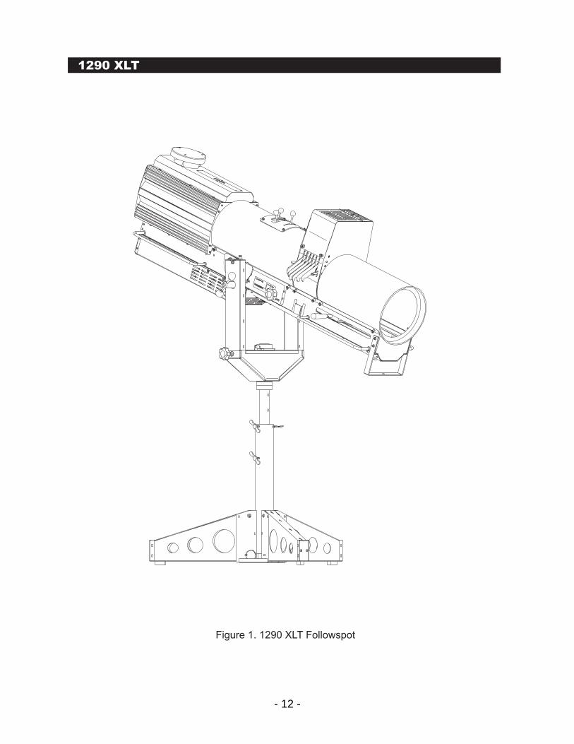
M2 Modular Followspots1290 XLT
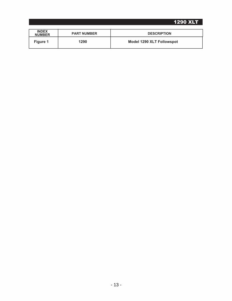
Figure 1. 1290 XLT Followspot
- 13 -
M2 Series M2 Modular Followspots
Figure 1 1290 Model 1290 XLT Followspot
INDEXNUMBER PART NUMBER DESCRIPTION
1290 XLT
- 14 -
M2 Modular Followspots1290 XLT
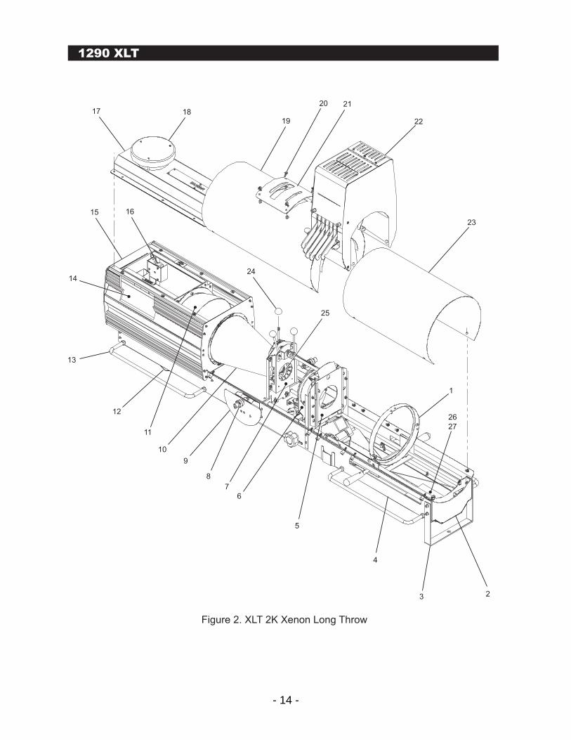
Figure 2. XLT 2K Xenon Long Throw
1
23
2219
17
15
11
12
7
6
5
4
2
26
27
3
8
9
10
13
14
16
1820 21
24
25
- 15 -
Figure 2 1290 XLT 2K Xenon Long Throw 1
1 129026X Front Lens Assembly (See Figure 3 for Detail) 1 2 12905A Front Partition 1 3 129092 Bale 1 4 129033 Belly Pan Assembly/Blower (See Fig. 7 for Detail) 1 5 129025X Focus Assembly (See Figure 8 for Detail) 1 6 129027X Rear Lens Assembly, Less Lens (See Fig 6 for Detail) 1 7 423 Shutter Assembly, Less Iris (See Fig. 5 for Detail) 1 8 338 Yoke Ball Bearing 4 9 129121R Yoke Mount (Right) 1 - 129121L Yoke Mount (Left) 1 10 129109 Light Cone 1 11 129012 10 Inch Reflector with Mount 1 12 403-243 Blower, 134 CFM, 240V 1 13 273 Handle, 18 Inch 4 14 932 Igniter, 80 Amp, Xenon 1 15 129020X Xenon Lamphouse Assembly 1 16 441X Air Flow Switch Assembly 1 17 129024X Lamphouse, Top Assembly 1 18 127514 Vent Cap With Mounting Hardware 1 18 129118X Vent Cap Hardware Kit 1 19 120659 Rear Cowling 1 20 W10 Washer, No. 10 4 20 W10SL Washer, Split, Lock, No. 10 4 20 S10-32X3/4P Screw, #10-32 x 3/4" Long, Phillips Pan Head 4 21 129125 Aperture Cover 1 22 129038X Color Boom Assembly (See Figure 4 for Detail) 1 23 129022X Front Cowling 1 24 120659 Knob, 1 Inch Ball, 1/4 - 20 Thread 3 25 120641 Iris 1 26 1290114 1290 Counterweight 1 27 494 Knob, 1/4-20, Aluminum (Knob not shown) 1
M2 Modular Followspots
INDEXNUMBER PART NUMBER DESCRIPTION QUANTITY
1290 XLT
- 16 -
1290 XLT
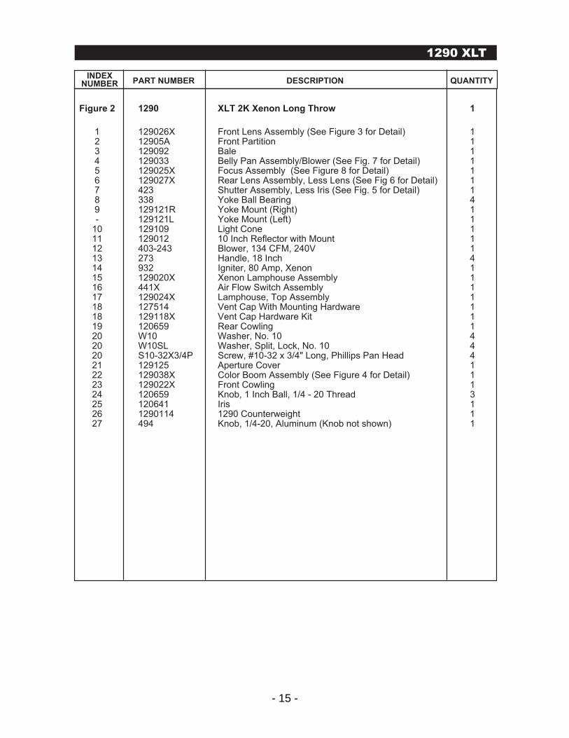
Figure 3. Front Lens Assembly
2
15
6
3
111
14
4
7
8
9
12
13
10
5
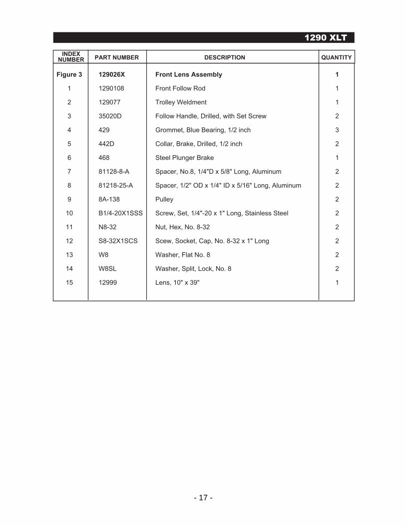
- 17 -
Figure 3 129026X Front Lens Assembly 1 1 1290108 Front Follow Rod 1 2 129077 Trolley Weldment 1 3 35020D Follow Handle, Drilled, with Set Screw 2
4 429 Grommet, Blue Bearing, 1/2 inch 3
5 442D Collar, Brake, Drilled, 1/2 inch 2
6 468 Steel Plunger Brake 1
7 81128-8-A Spacer, No.8, 1/4"D x 5/8" Long, Aluminum 2
8 81218-25-A Spacer, 1/2" OD x 1/4" ID x 5/16" Long, Aluminum 2
9 8A-138 Pulley 2
10 B1/4-20X1SSS Screw, Set, 1/4"-20 x 1" Long, Stainless Steel 2
11 N8-32 Nut, Hex, No. 8-32 2
12 S8-32X1SCS Scew, Socket, Cap, No. 8-32 x 1" Long 2
13 W8 Washer, Flat No. 8 2
14 W8SL Washer, Split, Lock, No. 8 2 15 12999 Lens, 10" x 39" 1
M2 Modular Followspots
INDEXNUMBER PART NUMBER DESCRIPTION QUANTITY
1290 XLT
- 18 -
1290 XLT
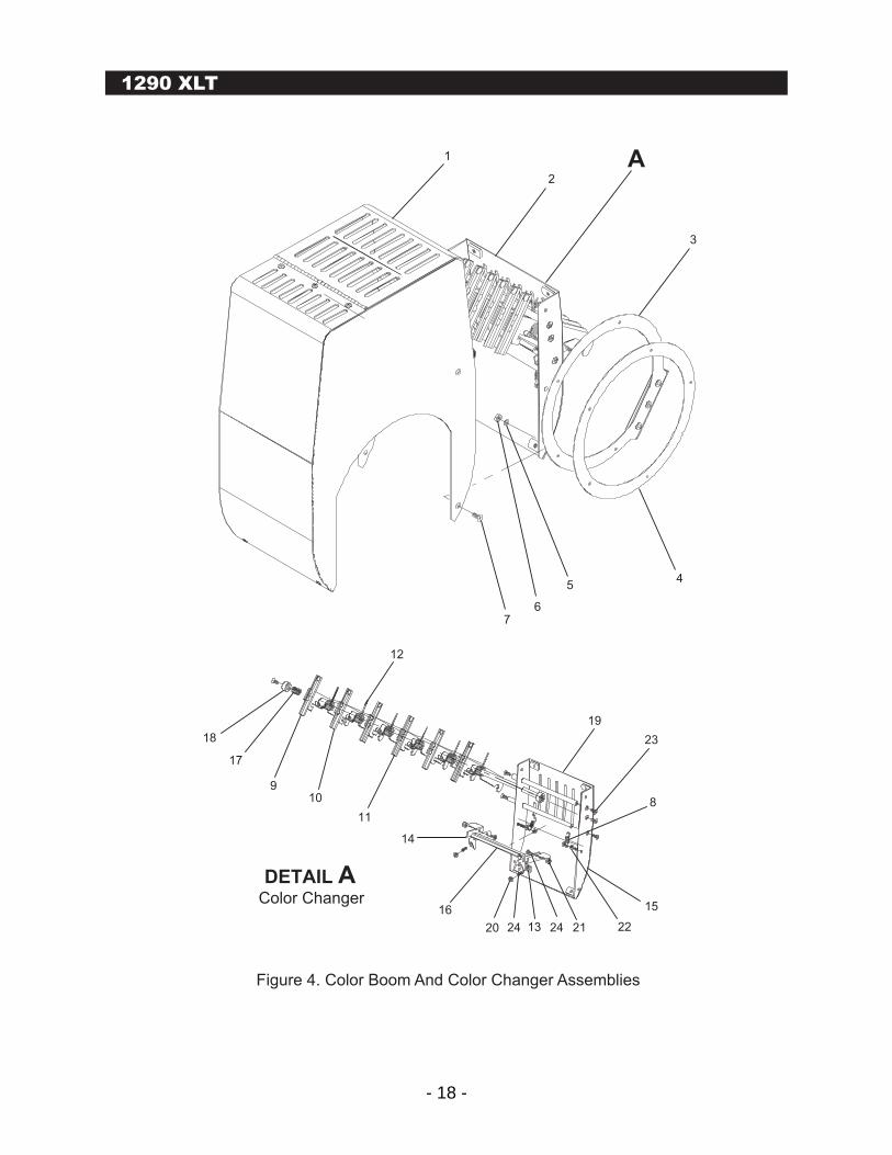
Figure 4. Color Boom And Color Changer Assemblies
4
3
5
67
1
2
8
23
19
15
222124132420
16
14
11
10
12
9
17
18
A
DETAIL AColor Changer
- 19 -
Figure 4 129038X Color Boom Assembly 1 1 1290385X Color Box Assembly 1
2 1290381X Color Changer Assembly (See Figure 5 For Breakdown) 1
3 1278110X Color Frame, 9", with Channel 6
4 1278110 Color Frame, 9", Ring Only 6
5 W10SL Washer, Split, Lock, No. 10 4
6 N10-32 Nut, Hex, Steel, No. 10-32 4
7 S10-32X1/2FH Screw, Phillips, Flat, No. 10-32 x 1/2" Long 4
8 120657 Spring, Color Boom Release 2
9 127826AX Short Channel Boom Arm 2
10 127826BX Medium Channel Boom Arm 2
11 127826CX Long Channel Boom Arm 2
12 127828 Spring, Boom Arm Torsion 6
13 1290118L Color Release Tab (Left) 1
14 1290118R Color Release Tab (Right) 1
15 1290381 Color Boom Plate Weldment 1
16 1290382 Large Clapper Bar 1
17 129122 1-1/2" Brake Spring 1
18 442 Collar, 3/8" I.D. 2
19 81865-1032-S Standoff, #10-32 x 6-3/4" Long, Stainless Steel 3
20 N10-32 Nut, #10-32 Hex Steel 2
21 N10-32 Lock Nut, #10-32 Nylon, Hex 2
22 N8-32 Nut, #8-32 Hex 4
23 S10-32X1/2FH Screw, #10-32 x 1/2" Long, Flat Phillips 6
24 S10-32X1/2SS Screw, 10-32 x 1/2" Long, Socket Set 2
25 S10-32X3/8P Screw, #10-32 x 3/8" Long Phillips Pan Head 2
M2 Modular Followspots
INDEXNUMBER PART NUMBER DESCRIPTION QUANTITY
1290 XLT
- 20 -
1
2
3
4
5
6
1290 XLT
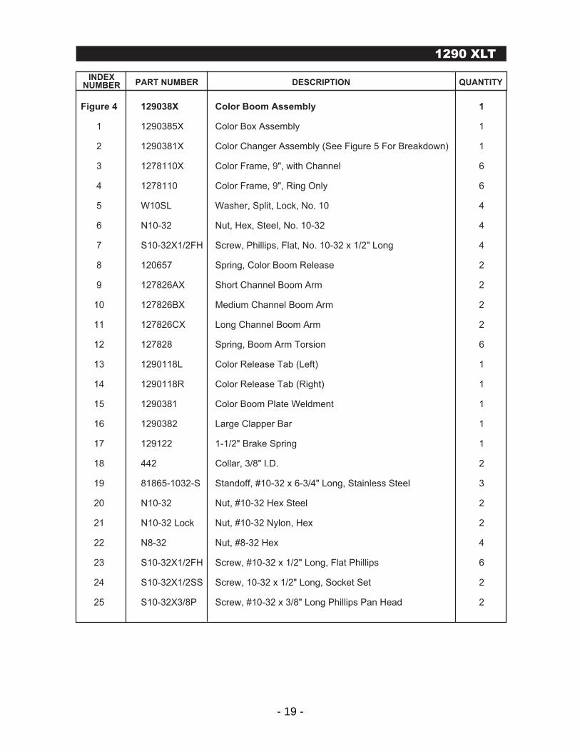
Figure 5. Shutter Assembly
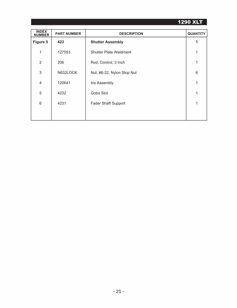
- 21 -
Figure 5 423 Shutter Assembly 1
1 127553 Shutter Plate Weldment 1
2 206 Rod, Control, 3 Inch 1
3 N632LOCK Nut, #6-32, Nylon Stop Nut 6
4 120641 Iris Assembly 1
5 4232 Gobo Slot 1
6 4231 Fader Shaft Support 1
M2 Modular Followspots
INDEXNUMBER PART NUMBER DESCRIPTION QUANTITY
1290 XLT
- 22 -
1290 XLT
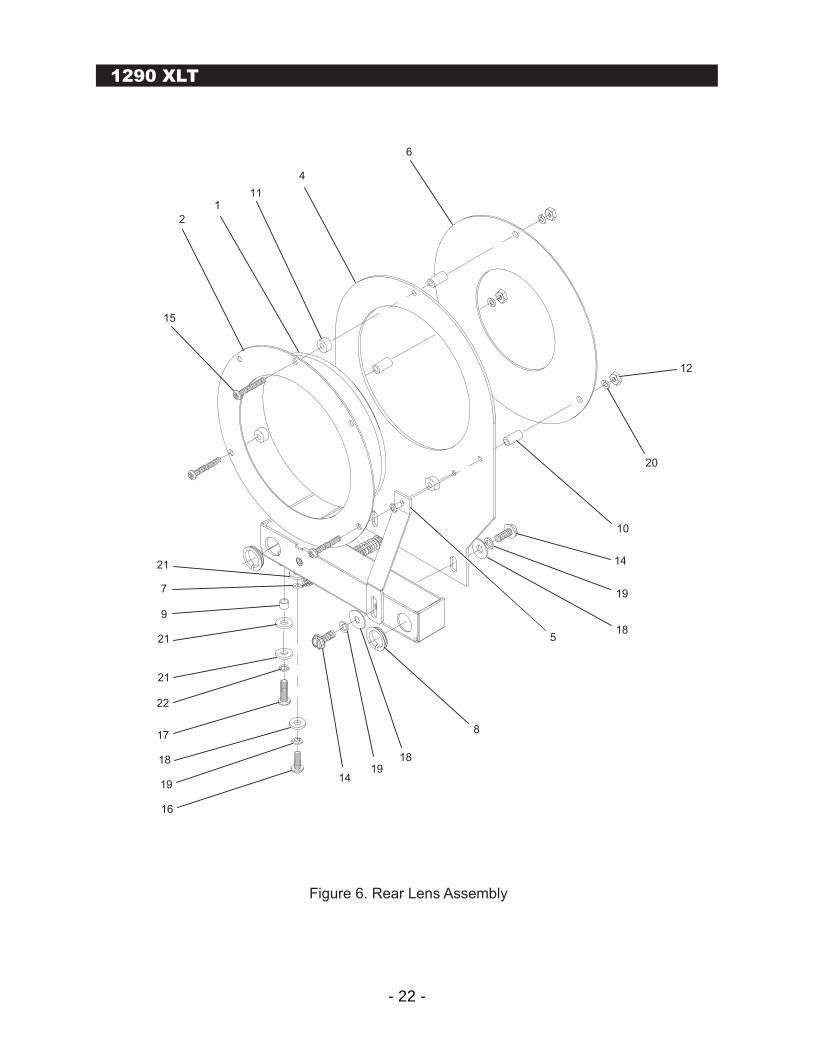
Figure 6. Rear Lens Assembly
6
4
111
2
15
8
18
18
19
19
14
14
10
20
12
5
7
21
9
21
21
22
17
16
19
18
- 23 -
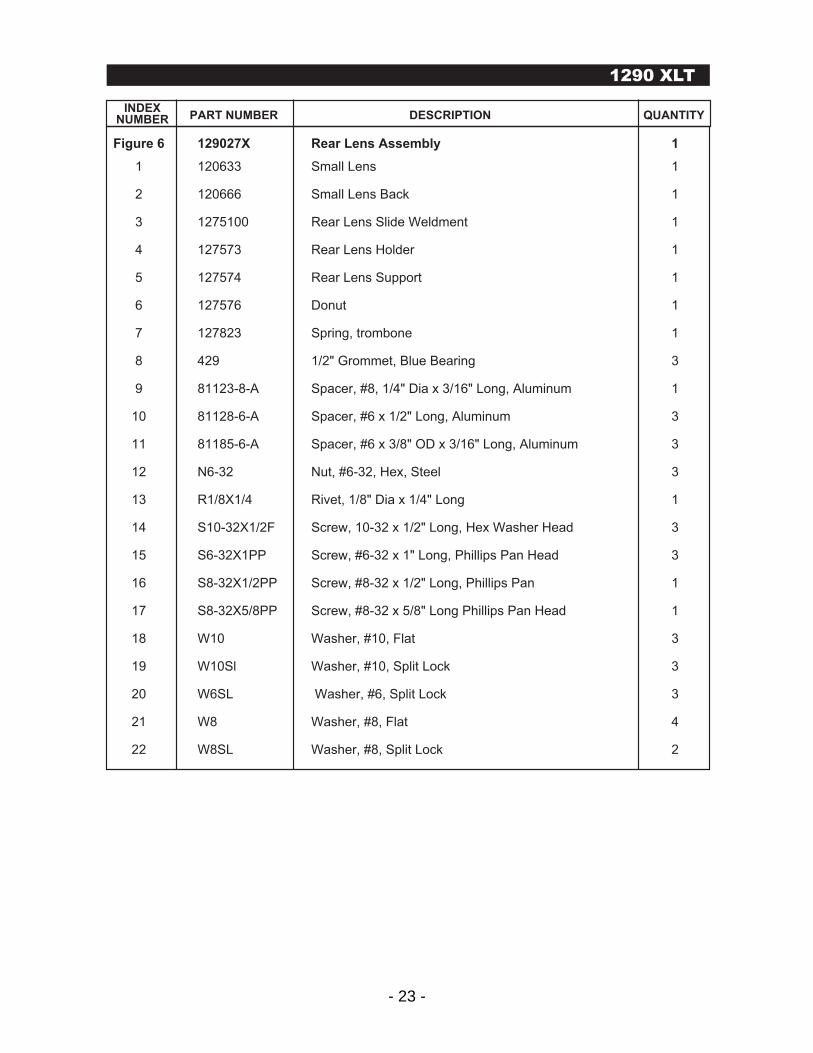
Figure 6 129027X Rear Lens Assembly 1
1 120633 Small Lens 1 2 120666 Small Lens Back 1 3 1275100 Rear Lens Slide Weldment 1
4 127573 Rear Lens Holder 1
5 127574 Rear Lens Support 1
6 127576 Donut 1
7 127823 Spring, trombone 1
8 429 1/2" Grommet, Blue Bearing 3
9 81123-8-A Spacer, #8, 1/4" Dia x 3/16" Long, Aluminum 1
10 81128-6-A Spacer, #6 x 1/2" Long, Aluminum 3
11 81185-6-A Spacer, #6 x 3/8" OD x 3/16" Long, Aluminum 3
12 N6-32 Nut, #6-32, Hex, Steel 3
13 R1/8X1/4 Rivet, 1/8" Dia x 1/4" Long 1
14 S10-32X1/2F Screw, 10-32 x 1/2" Long, Hex Washer Head 3
15 S6-32X1PP Screw, #6-32 x 1" Long, Phillips Pan Head 3
16 S8-32X1/2PP Screw, #8-32 x 1/2" Long, Phillips Pan 1
17 S8-32X5/8PP Screw, #8-32 x 5/8" Long Phillips Pan Head 1
18 W10 Washer, #10, Flat 3
19 W10Sl Washer, #10, Split Lock 3
20 W6SL Washer, #6, Split Lock 3
21 W8 Washer, #8, Flat 4
22 W8SL Washer, #8, Split Lock 2
M2 Modular Followspots
INDEXNUMBER PART NUMBER DESCRIPTION QUANTITY
1290 XLT
- 24 -
1290 XLT
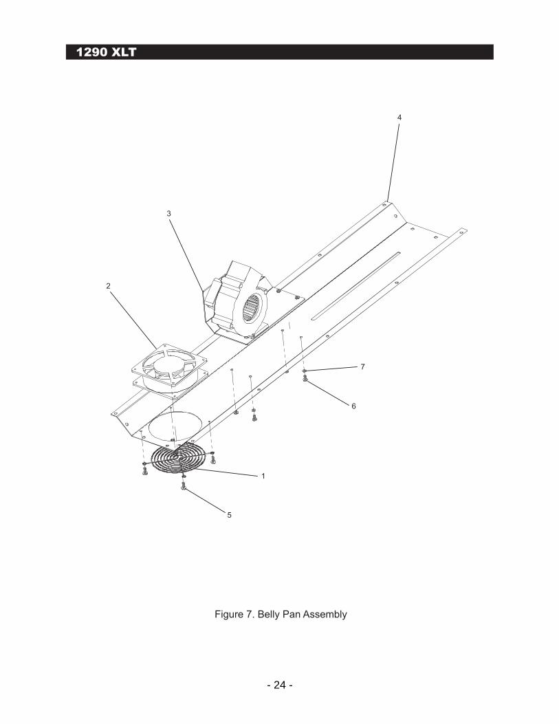
Figure 7. Belly Pan Assembly
4
3
2
1
5
6
7

- 25 -
Figure 7 129033X Belly Pan Assembly 1
1 120638 Fan Guard, 4.5 inch 1
2 120715 100 CFM Axial Fan 1
3 129015X Front Blower Assembly 1
4 129033 Belly Pan 1
5 S10-32X1/2F Screw, Hex, Washer Head, No. 10-32 x 1/2 inch long 4
6 S10-32X3/8P Screw, Phillips, Pan Head, No. 10-32 x 3/8 inch long 4
7 W10SL Washer, Split Lock, No. 10 4
M2 Modular Followspots
INDEXNUMBER PART NUMBER DESCRIPTION QUANTITY
1290 XLT
- 26 -
1290 XLT
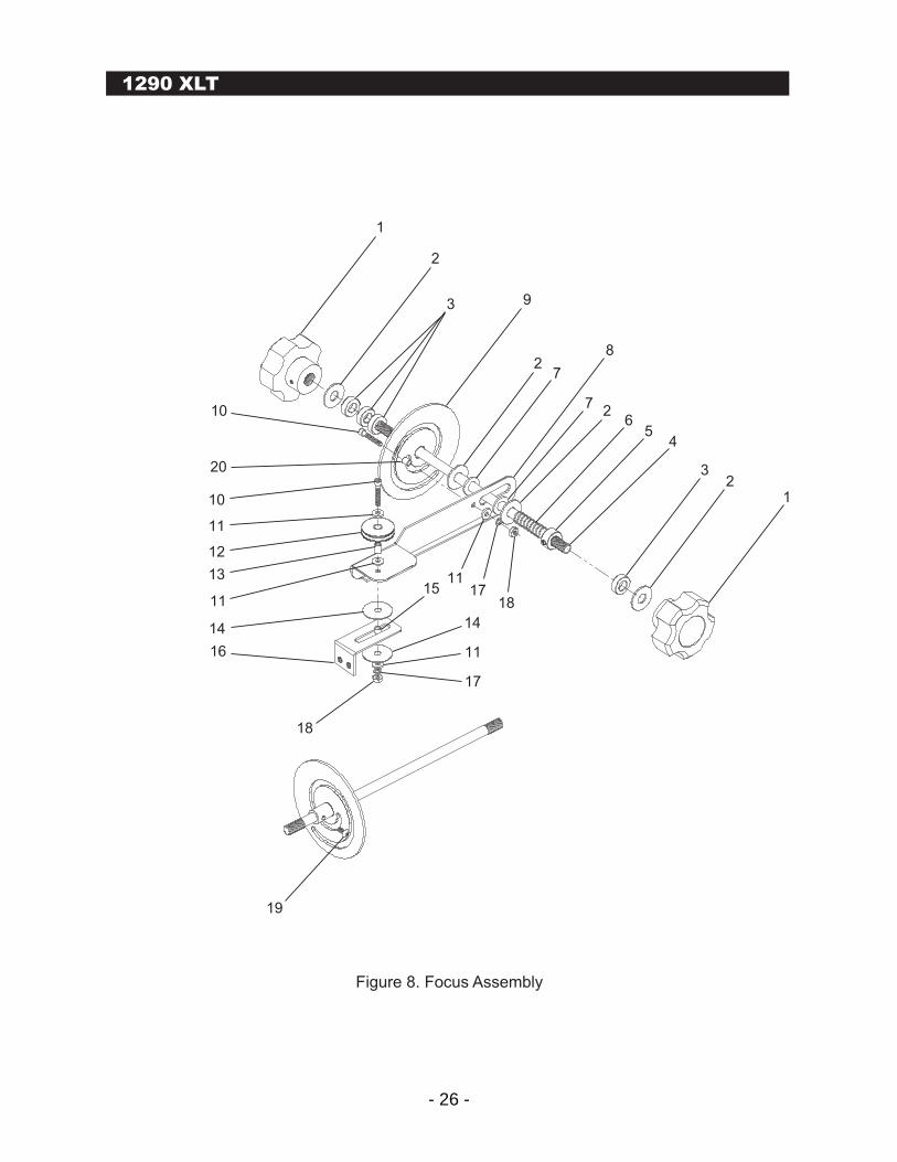
Figure 8. Focus Assembly
1117
1815
14
11
17
19
18
16
14
13
12
11
11
10
10
20
1
2
3 9
27
8
72
65
4
32
1
- 27 -
Figure 8 129025X Focus Assembly 1
1 35022X Knob, 2-1/2" with Set Screw 2 2 W3/8 Washer, Flat, 3/8", Regular Series 4 3 81279-38-A Spacer, 3/4" O.D. x 3/8" I.D. x 1/4" Long, Aluminum 4 4 129107 Rod, Focus, 10-3/4" 1 5 442R Collar, 3/8", Reamed 1 6 129122 Spring, Brake, 1-1/2" 1 7 85179-F-375 Washer, Brake, Fiber 2 8 1290412 Focus Push Arm 1 9 1290411X Focus Cam 1 10 S8-32X1SCS Screw, #8-32 x 1" Long, Socket Cap 2 11 W8 Washer, 3/8", Flat, Regular Series 4 12 8A-138 Pulley 1 13 81126-8-S Spacer, #8, 1/4" Dia. x 3/8" Long, Steel 1 14 W1/4X1-1/8N Washer, Nylon, 1-1/8" Dia., 1/8" H 2 15 81123-8-S Spacer, #8, 1/4" Dia. x 3/16" Long, Steel 1 16 1290413 Bracket, Push Arm 1 17 W8SL Washer, Split, #8, Flat 2 18 N8-32 Nut, #8-32 Hex 2 19 S8-32X3/8BH Screw, #8-32 x 3/8" Long, Button Head 1 20 81128-8-S Spacer, #8, 1/4" Dia. x 1/2" Long, Steel 1
M2 Modular Followspots
INDEXNUMBER PART NUMBER DESCRIPTION QUANTITY
1290 XLT
- 28 -
1290 XLT
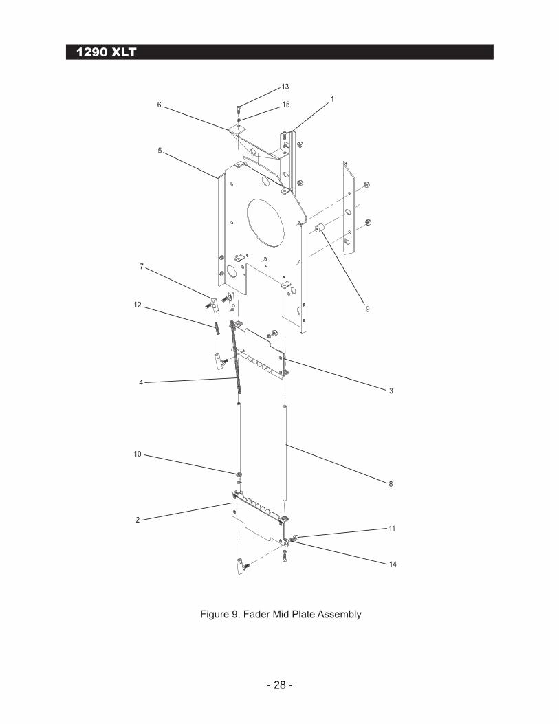
Figure 9. Fader Mid Plate Assembly
1
2
34
5
6
7
8
9
10
11
14
12
13
15
- 29 -
Figure 9 129051X Fader Mid Plate Assembly 1
1 1290107 Effects "Z" Bracket Pair with Hardware 1 2 1290116 Lower Fader Shutter Blade 1 3 1290117 Upper Fader Shutter Blade 1 4 1290120 6-19/32" Long 10-32 Rod 1 5 129051 Fader Mid Plate Fastment 1 6 129127 Fader Shaft Support, 1/2" 1 7 210 Ball Joint 4 8 289 Standoff, #6-32 x 1/4" Dia x 8-3/4" Long, Brass 2 9 81885-1032-A Standoff, #10-32 x 1/2" Dia x 1/2" Long, Aluminium 1 10 N10-32 Nut, #10-32 Hex, Steel 2 11 N10-32LOCK Nut, #10-32, Nylock, Hex 2 12 S10-32XISSS Screw, #10-32 x 1" Long, Set 1 13 S6-32X1/2SCS Screw, #6-32 x 1/2" Long, Socket Cap 3 14 W10SL Washer, #10, Split Lock 4 15 W6SL Washer, #6, Split Lock 4
M2 Modular Followspots
INDEXNUMBER PART NUMBER DESCRIPTION QUANTITY
1290 XLT
- 30 -
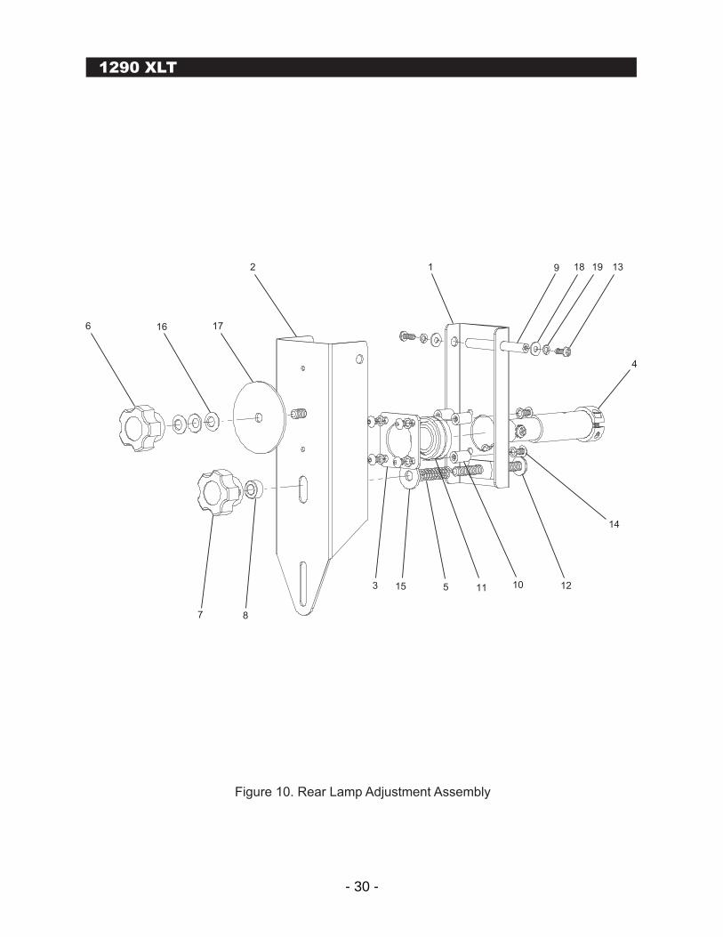
1290 XLT
Figure 10. Rear Lamp Adjustment Assembly
2
17166
7 8
3 15 5 11 10 12
14
4
13191891
- 31 -
Figure 10 129031X Rear Lamp Adjustment Assembly 1
1 1290100 Inner Rear Lamp Support 1 2 1290101 Outer Rear Lamp Support 1 3 1290102 Rear Lamp Bearing Support 1 4 1290103X Rear Lamp Insulator Assembly 1 5 1290122 Spring, 2" 1 6 240 Knob, Focus, 1/4-20 1 7 240D Knob, Focus, 1/4-20, Drilled 1 8 81217-25-A Spacer, 1/4" ID x 1/4" Long, x 1/2" OD, Aluminum 1 9 81710-632-A Standoff, #6-32 x 1/4" Dia x 2-1/4" Long, Aluminum 1 10 81824-832-A Standoff, #8-32, THD x 3/8" Dia x 1/2" Long, Aluminum 4 11 8C0M10 Bearing, Spherical 1 12 S1/4-20X2/12 Screw, 1/4-20 x 2-1/2" Long, Phillips 1 13 S6-32X3/8PP Screw, #6-32 x 3/8" Long, Phillips, Pan Head 2 14 S8-32x5/16B Screw, #8-32 x 5/16" Long, Button Head 7 15 W1/4 Washer, 1/4" DIA., Regular series 1 16 W1/4SPRING Washer, 1/4", Spring 3 17 W2X1/4 Washer, 2" DIA. x 1/4" ID 1 18 W6 Washer, #6, Flat 2 19 W6SL Washer, #6, Split Lock 2 20 W8SL Washer, #8, Split Lock 7
M2 Modular Followspots
INDEXNUMBER PART NUMBER DESCRIPTION QUANTITY
1290 XLT
- 32 -
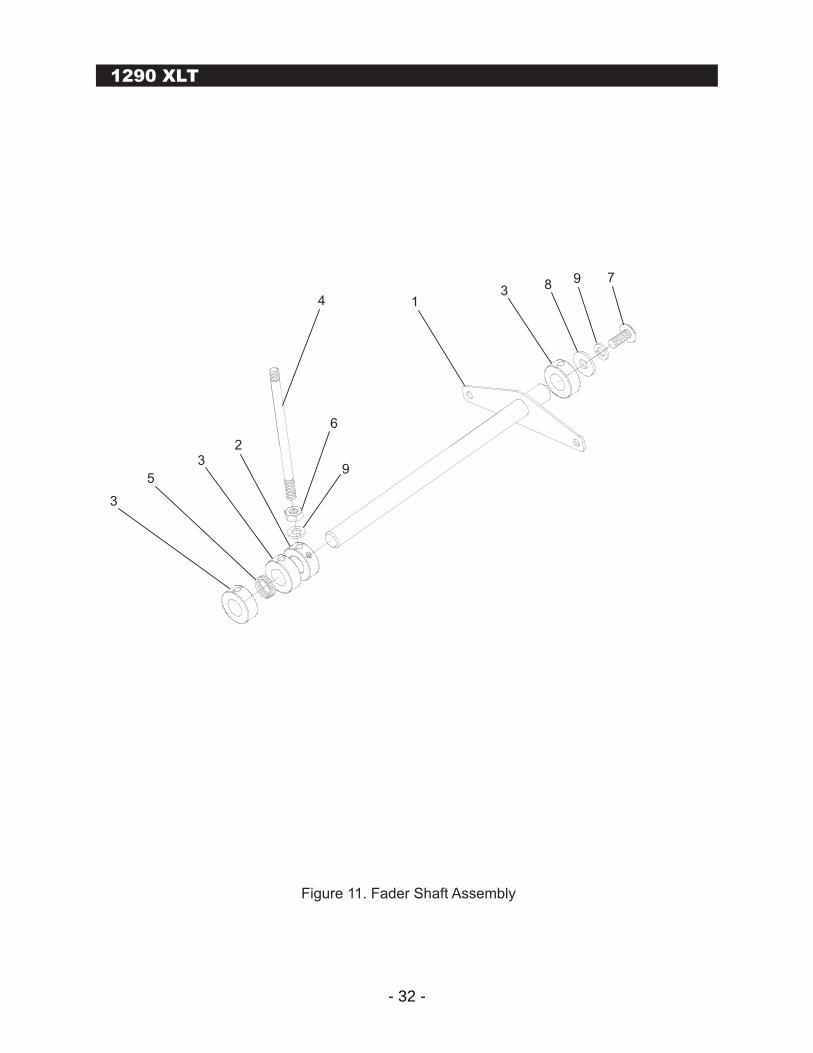
1290 XLT
Figure 11. Fader Shaft Assembly
3
5
32
9
6
4 13 8 9 7
- 33 -
Figure 11 1290379 Fader Shaft Assembly 1
1 1290379W Fader Shaft Weldment 1
2 251S Collar, 1/2" 1
3 251R Collar, 1/2", Reamed 3
4 312 Control rod, 4-1/4" x 1/4-20 1
5 8LC-045H-01S Spring, Fader Brake 1
6 N1/4-20 Nut, 1/4-20, Hex, Steel 1
7 S1/4-20X5/8S Screw, 1/4-20 x 5/8" Long, Slotted Truss Head 1
8 W1/4 Washer, 1/4" DIA., Regular Series 1
9 W1/4SL Washer, 1/4", Split Lock 2
M2 Modular Followspots
INDEXNUMBER PART NUMBER DESCRIPTION QUANTITY
1290 XLT
- 34 -
1290 XLT
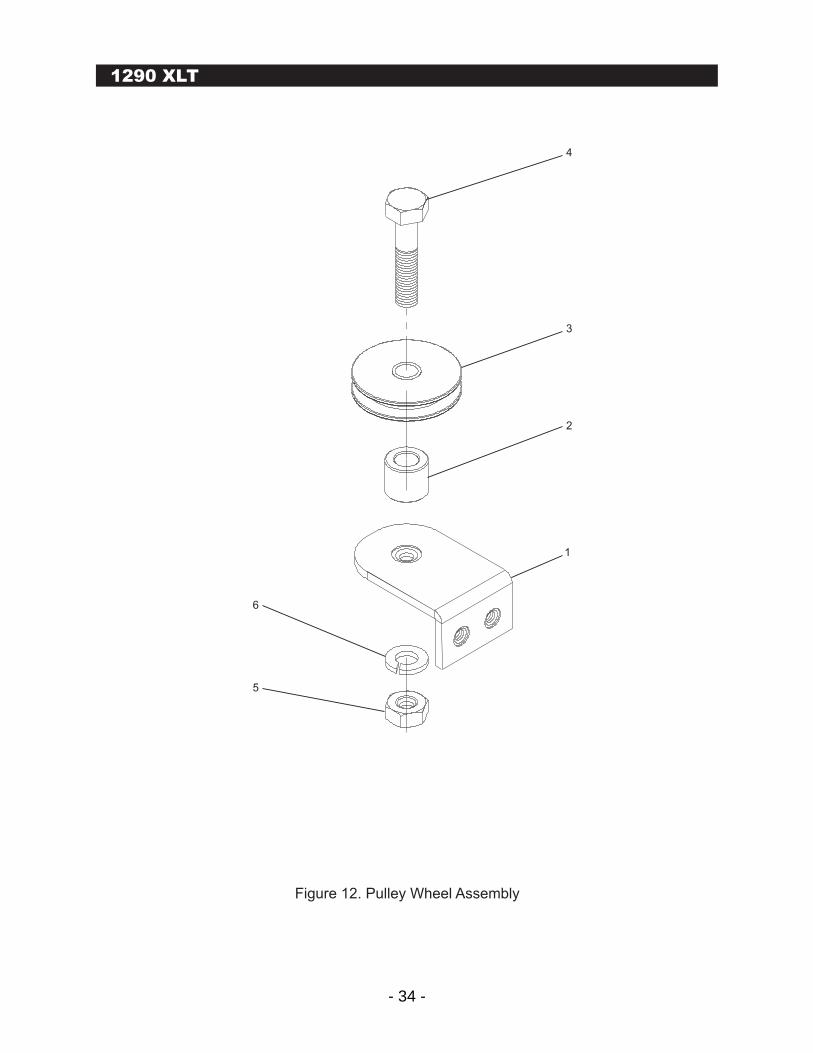
Figure 12. Pulley Wheel Assembly
5
6
1
2
3
4
- 35 -
Figure 12 1290380 Pulley Wheel Assembly 1
1 129079 Pulley Bracket 1 2 81220-25-A Spacer, 1/4" ID x 7/16" Long x 1/2" OD, Aluminum 1 3 8A-138 Pulley 1 4 B1/4-20X114 Bolt, 1/4-20 x 1-1/4" Long, Hex, Steel 1 5 N1/4-20 Nut, 1/4-20, Hex, Steel 1 6 W1/4SL Washer, 1/4" Split Lock 1
M2 Modular Followspots
INDEXNUMBER PART NUMBER DESCRIPTION QUANTITY
1290 XLT
- 36 -
1290 XLT
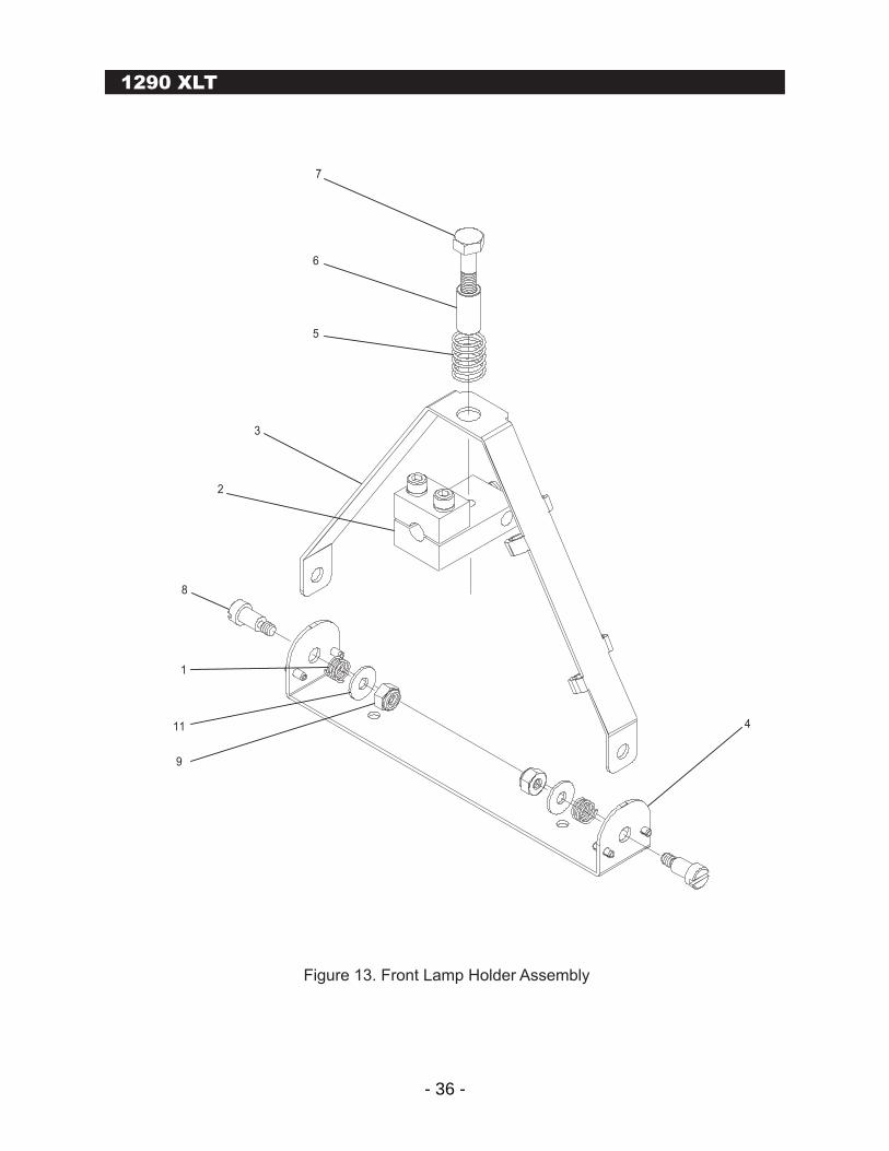
Figure 13. Front Lamp Holder Assembly
7
6
5
3
2
8
1
11
9
4
- 37 -
Figure 13 129123X Front Lamp Holder Assembly 1
1 126664 Spring 2 2 129040X Front Lamp Contact Assembly 1 3 129123 Front Lamp Bale 1 4 129123A Front Lamp Bale Bracket 1 5 129124 Spring, Lamp Contact 1 6 81194-12-S-12 Spacer, 3/8" OD x 1/4" ID x 3/4" Long 1 7 B1/4-20X114 Bolt, 1/4-20 x 1-1/4" Long, Hex, Steel 1 8 B10-32X3/8SB Bolt, #10-32 x 3/8" Long, Shoulder 2 9 N10-32LOCK Nut, #10-32 NYLOCK, Hex 2 10 P1/8x3/8ROLE Roll Pin, 1/8" DIA. x 3/8" Long 4 11 W10 Washer, #10, Flat 2
M2 Modular Followspots
INDEXNUMBER PART NUMBER DESCRIPTION QUANTITY
1290 XLT
- 38 -
1290 XLT
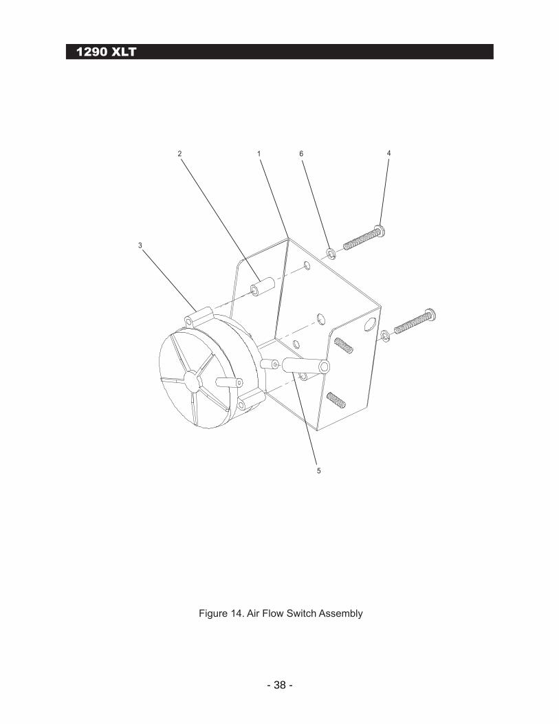
Figure 14. Air Flow Switch Assembly
5
3
2 1 6 4
- 39 -
Figure 14 441X Air Flow Switch Assembly 1
1 441 Pressure Switch Mount 1 2 81128-6-A Spacer, #6 x 1/2" Long, Aluminum 3 3 89-45 Switch, Air Pressure 1 4 S6-32X1PP Screw, #6-32 x 1" Long, Phillips, Pan Head 3 5 T30 Tube, UV Resistant, 3/16" x 1-1/4" Long 1 6 W6SL Washer, #6, Split Lock 3
M2 Modular Followspots
INDEXNUMBER PART NUMBER DESCRIPTION QUANTITY
1290 XLT
- 40 -
1290 XLT
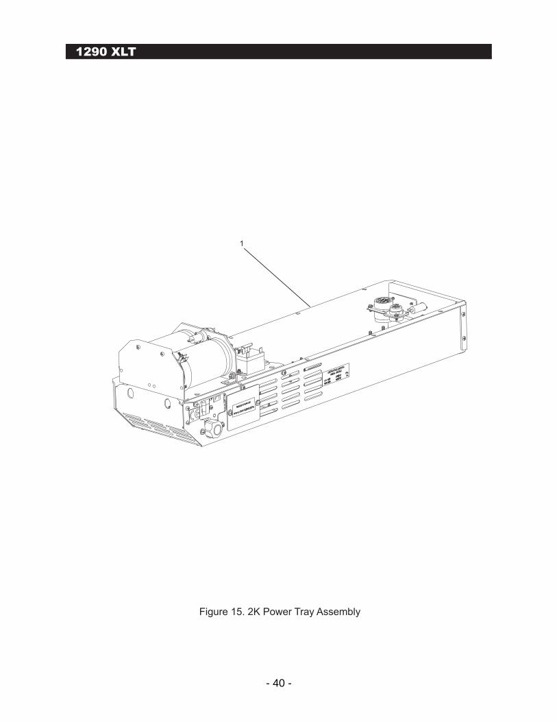
Figure 15. 2K Power Tray Assembly
1
- 41 -
Figure 15 129028X 2K Power Tray Assembly 1
Contact Lycian Stage Lighting for information
M2 Modular Followspots
INDEXNUMBER PART NUMBER DESCRIPTION QUANTITY
1290 XLT
- 42 -
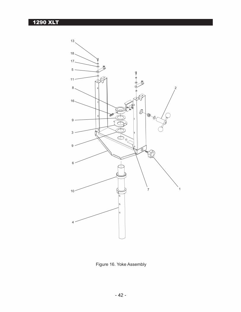
1290 XLT
Figure 16. Yoke Assembly
13
18
17
5
11
8
16
2
9
3
9
6
10
4
7 1
- 43 -
Figure 16 13228X Yoke Assembly 1
1 120628 Knob, 2-1/2", 5 Point, M-3/8 2
2 132213X Brake and Handle Assembly 1
3 132232 Rotation Stop Disk, 7 Gauge, Large 1
4 132233 Yoke Pole With Collar 1
5 13224 Yoke Hold Down Clip With Southco 2
6 13229W Tall Yoke Weldment 1
7 282 Yoke Label 1
8 306 Collar, 2" 1
9 326 Washer, Pan, 2" 2
10 364 Bearing, Thrust, 2-1/16" 1
11 81215-25-A Spacer, #10 x 1/2 Dia. x 1/8" High, Aluminum 2
12 8LHL 500 C1 Spring 1
13 B1/4-20X5/8S Bolt, 1/4-20 x 5/8" Long, Truss Head 2
14 P1/2X1-1/2D Pin, Dowl, 1/2" Dia. x 1-1/2" Long 3
15 P1/2x2D Pin, Dowl, 1/2" Dia. x 2" Long 1
16 S1/2-13X1.2X Screw, 1/2-13 x 1-1/2" Long, Socket Set 1
17 W1/4 Washer, 1/4" Dia., Regular Series 2
18 W1/4SL Washer, 1/4", Split Lock 2
M2 Modular Followspots
INDEXNUMBER PART NUMBER DESCRIPTION QUANTITY
1290 XLT
- 44 -
1290 XLT
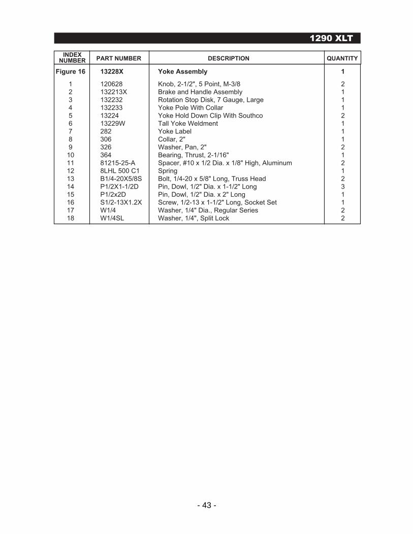
Figure 17. Base Stem Folding Assembly
1
43
2
- 45 -
Figure 17 13227FX Base Stem Folding Assembly 1
1 13227FX Base Stem Folding Assembly 1
2 13229 Pin, Quick Release 3
3 308 "Tee" Handle, 3/8", Gold 2
4 435 Fastpin, 3.3" 1
M2 Modular Followspots
INDEXNUMBER PART NUMBER DESCRIPTION QUANTITY
1290 XLT
- 46 -
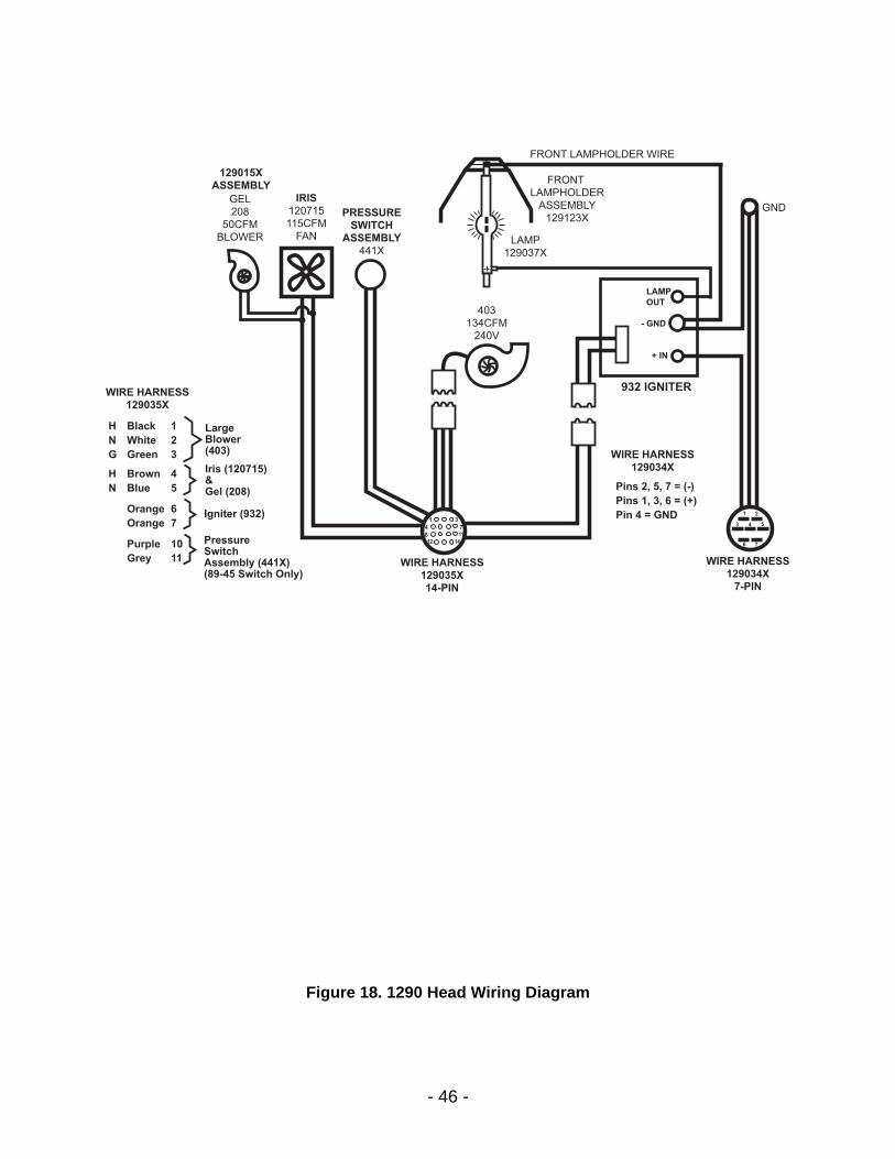
LAMP
OUT
- GND
+ IN
GND
WIRE HARNESS
129034X
7-PIN
WIRE HARNESS
129034X
WIRE HARNESS
129035X
14-PIN
FRONT LAMPHOLDER WIRE
403
134CFM
240V
PRESSURE
SWITCH
ASSEMBLY
441X
IRIS
120715
115CFM
FAN
GEL
208
50CFM
BLOWER
129015X
ASSEMBLY
932 IGNITER
1
4
812 14
117
31 2
3 4 5
6 7
LAMP
129037X
H Black 1
N White 2
G Green 3
H Brown 4
N Blue 5
Orange 6
Orange 7
WIRE HARNESS
129035X
LargeBlower(403)
Iris (120715)&Gel (208)
Igniter (932)
Purple 10
Grey 11
PressureSwitchAssembly (441X)(89-45 Switch Only)
Pins 2, 5, 7 = (-)
Pins 1, 3, 6 = (+)
Pin 4 = GND
FRONT
LAMPHOLDER
ASSEMBLY
129123X
Figure 18. 1290 Head Wiring Diagram