model 205 ce vibration meter - balmac inc. w artwork.pdf · page 3 model 205 ce section 1 -...
TRANSCRIPT
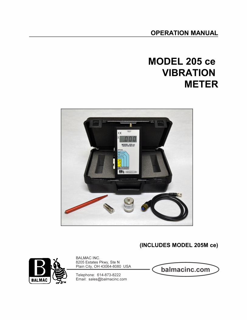
OPERATION MANUAL
MODEL 205 ce VIBRATION
METER
(INCLUDES MODEL 205M ce)

Page 2 MODEL 205 ce
TABLE OF CONTENTS
SECTION TITLE PAGE
1. INTRODUCTION 3Description 3
2. FEATURES 4Batteries 4Controls 4Vibration Pickup 4
3. OPERATION 44. MEASUREMENTS 5
Velocity 5Displacement 5Acceleration 5
5. VIBRATION SEVERITY (TABLES) 6-76. TROUBLESHOOTING 87. SUPPORT 98. PARTS 99. DISPOSAL 910. APPLICATIONS 1011. SPECIFICATIONS 11
Model 205 ce & 205M ce 11(Back Cover). WARRANTY & SERVICE 12
Balmac assumes no responsibility for errors or omissions. Neither is any liability assumed for damagesresulting from the use of the information contained herein.
Specifications are subject to change without prior notice.
WARNING: Exercise extreme caution when performing any task on rotating machinery. Failure to do somay result in equipment damage or personal injury. Familiarize yourself with the equipment beforeattempting to perform any operation.
WARNING: ROTATING MACHINERY HAS POTENTIALLY DANGEROUS MOVING PARTS ANDSHOULD BE GUARDED IN ACCORDANCE SAFETY TO SAFETY REGULATIONS.
This manual is for the Balmac Vibration Meters Models 205 ce and 205M ce.

Page 3 MODEL 205 ce
SECTION 1 - INTRODUCTION
Description
The Balmac Model 205 ce Vibration Metertakes the guesswork out of machinerymaintenance and vibration studies. There are many factors that can causeexcessive vibration in rotating machinery. Theseinclude worn bearings and couplings; pipe andfoundation damage; broken mounting bolts;misalignment and unbalance. Vibration measurements (or a vibrationmaintenance program) can help prevent thesetypes of failures by detecting machine problemsbefore anything serious happens.
Vibration measurements provide a quick checkof machinery condition. The readings from theModel 205 ce are used for analysis and trending. The Model 205 ce Vibration Meter is easy tooperate. It can be used by practically anyone forchecking the overall (broadband) vibration leveland vibration condition. The hand-heldinstrument is lightweight and battery powered. Itmeasures the acceleration (g’s), velocity (inchesper second) and displacement (mils) of vibration. The Model205M ce Vibration Meter is calibratedin METRIC units.
Balmac Model 205 ce &205M ce Vibration Meter
The Model 205 ce Vibration Meter Kit includes: (1) Model 205 ce Vibration Meter with Batteries; (1) Model 601 AccelerometerVibration Pickup; (1) Model 059-5' Vibration Pickup Cable; (1) Model 052 Magnetic Base Clamp; (1 ea) Model 032A Carrying Case,Manual and Calibration Certificate (not shown).

Page 4 MODEL 205 ce
SECTION 2 - FEATURES
Battery
The Balmac Model 205 ce Vibration Meterscome equipped with 4 Size AA 1.5 Volt standardalkaline batteries. Alkaline batteries arerecommended for maximum operation time.LOW BATTERY - a low battery symbol “Lo-Bat”or “¹”, will display (with instrument power “ON”)when the batteries needs replacement.REPLACING BATTERIES - (procedure)1. Turn the 205 ce “OFF”.2. Remove two #4-32 Phillips-head screwsfrom back battery cover. Remove cover.3. Locate battery holder and carefully removeold batteries.4. Insert new batteries as indicated by outlinesin bottom of battery compartment. Replacecover and tighten screws.
Controls
1. OFF/ON (Grey) - Self-latching button powersthe Model 205 ce on and off.2. DISP, VEL, ACC (Black) - Self-latching,vibration amplitude buttons (see Section 4“Measurements” for a detailed explanation of themerits of each).3. RANGE BUTTONS (200, 20, 2, Very LowRange) (White) - Self-latching Full Scale Rangeselector buttons. (205M ce = 2000, 200, 20VLR).
Vibration Pickup
The Balmac Model 205 ce Vibration Meter usesthe Model 601 Pickup. The Model 601 connectsto the Model 059-5' Straight Pickup Cable (2-conductor, shielded cable). The 059-5' cableconnects to the input connector at the top of theModel 205 ce. It is recommended that the Model 601 Pickupbe mounted on 1/4-28 UNF stud, or on theModel 052 Magnetic Base Clamp.
NOTE: DO NOT SLAM OR BANG THE PICKUPWHEN MOUNTING WITH THE MAGNETICBASE. THIS CAN DAMAGE THE PICKUP.
SECTION 3 - OPERATION
1. Connect the Model 601 Pickup to the Model059-5' Pickup Cable.2. Select appropriate mounting accessory(Model 052 Magnetic Base Clamp) and connectto the Model 601 Pickup.3. Connect cable and pickup assembly to theModel 205 ce.4. Depress the OFF/ON switch to power theinstrument “ON”.5. Select then depress one of the blackAmplitude Measurement buttons:ACC = Acceleration = g’s (peak)(in/sec²)
205M ce = g’s mm/sec²VEL = Velocity = Inches Per Second (peak)
205M ce = Velocity = mm/secDISP = Displacement = Mils (peak to peak)
205M ce = Displacement = µm6. Select then depress one of the gray Rangebuttons (2, 20, 200 or Very Low Range)(205M ce= 20, 200, 2000 or Very Low Range). Changethe Range button to another range if necessaryuntil the AMPLITUDE meter reads withoutindicating an overrange condition. (Over Range Display = 1 __ __ __ [1 with 3 blank digits]). Read vibration amount directly.
NOTE: The best recommended permanentmounting method is using a stud on a clean flatsurface (like on the magnetic base).CAUTION: The mounting stud must not extendinto the pickup more than 0.2". Hand tighten thepickup. DO NOT WRENCH THE PICKUPONTO THE MOUNTING. The pickup’s axis ofsensitivity is perpendicular to the mounting base. The pickup may be used and mounted in anydirection (horizontal, vertical, axial). SeeVibration Pickup specification on Page 11.

Page 5 MODEL 205 ce
SECTION 4 - MEASUREMENTS
VELOCITY is the recommended setting formachinery severity vibration readings with theModel 205 ce Vibration Meter. The destructiveforces generated in today’s higher speedmachines are more proportional to vibrationvelocity than either displacement or acceleration. For example, it is very unusual for someone toarrive on the scene of an automobile accidentand ask “How far did they come?”(Displacement), or “How fast did they stop?”(Acceleration). The common question is “Howfast were they going when they hit?” (Velocity)
DISPLACEMENT is the peak to peak distance apart is moving measured in “mils.” One milequals one thousandth of an inch (.001"). Whenmeasuring in mils, the operating speed must beknown to establish a vibration condition limit. (Example: a cooling tower fan operating at 175RPM vibrating at 10 mils may be considered ingood condition. An electric motor operating at1750 and vibrating at 10 mils typically requiresimmediate attention.)
ACCELERATION - is useful for detecting thedeterioration and defects or rolling elementbearings and gears. An acceptable level formost machines is less than 0.5 g’s. If the level ishigher, the bearing may be defective and shouldbe analyzed. An acceptable level of g’s can beestablished by comparing similar machines andby studying vibration trends.
Table 1: Comparison of Velocity, Displacement and Acceleration
SPEEDRPM(cpm X 60)
DISPLACEMENTMILS(Peak to Peak)
VELOCITYIN/SEC(Peak)
ACCELERATIONG’s(Peak)
175 21.9 0.2 0.00945
1750 2.19 0.2 0.0945
17,500 0.219 0.2 0.945
175,000 0.0219 0.2 9.45

Page 6 MODEL 205 ce
SECTION 5 - VIBRATION SEVERITY
The following vibration charts are recommended for determining machinery condition based on readingstaken with the Balmac Model 205 ce Vibration Meter:
VIBRATION WARNING LEVELS
The vibration levels listed below may be used as a guide for selecting and setting the limits on Vibration Transmitters and VibrationSwitches. The limits are intended to serve as a guide for machines of similar types, when measured in accordance with thestandard procedures for evaluating vibration. In some cases, requirements may be more or less stringent, or may not apply. Reference ISO and ANSI standards.
VIBRATION VELOCITY CLASS OF MACHINERY
Vibration (ips) Class-1 Class-2 Class-3 Class-4
0.01 ips GOOD GOOD GOOD GOOD
0.02 ips GOOD GOOD GOOD GOOD
0.03 ips GOOD GOOD GOOD GOOD
0.06 ips FAIR GOOD GOOD GOOD
0.08 ips FAIR FAIR GOOD GOOD
0.1 ips ROUGH FAIR FAIR GOOD
0.2 ips N/A ROUGH FAIR FAIR
0.4 ips N/A N/A ROUGH FAIR
0.6 ips N/A N/A N/A ROUGH
0.8 ips N/A N/A N/A N/A
1.0 ips N/A N/A N/A N/A
Class-1: Individual components, integrally connected with the complete machine in its normal operating condition.Small Electric Motors, Precision Machines, Turbines
Class-2: Medium size machinery without special foundations, rigidly mounted engines, or machines on special foundations.Gear Boxes, Pumps, M-G Sets, Fans
Class-3: Large prime movers mounted on heavy, rigid foundations.Compressors, Blowers, Hammer mills, Engines
Class-4: Large prime movers mounted on relatively soft, light-weight structures.Crushers, Reciprocating Machinery, Vibrating Conveyors

Page 7 MODEL 205 ce

Page 8 MODEL 205 ce
SECTION 6 - TROUBLESHOOTING
The following is a list of troubleshootingquestions:
Are the pickup and cable in good condition andconnected properly?Is the power ON? Is the battery good?Is the display on?Are the switches inoperative, or experiencingother switching problems?
TROUBLESHOOTING GUIDE
Symptom: No DisplayPossible Cause: No power or supply voltageSolution: [1] Check power source
(batteries). Replace ifnecessary.[2] Check power OFF/ONswitch.
Symptom: No Indication on Meter DisplayPossible Cause: No vibration signalSolution: [1] Check vibration pickup and
cable.[2] Possible defective pickup.[3] Possible defective display.
Symptom: Amount Readings UnstablePossible Cause: [1] Machine defect
[2] Improper setup (low range)Solution: [1] Check vibration pickup for
proper installation.[2] Check for loose machinecomponents.[3] Verify pickup and cableconnections.[4] Signal to noise ratio is low(low range in displacement). Reduce noise, increaseAmplitude range, or changeAmplitude units.
SECTION 7 - SUPPORT
TECHNICAL SUPPORT - For additionaltechnical information, contact Balmac. Additional information about vibration is availablein our Vibration Analysis Training Manual andour “B” Book Series. For information on vibration standards for ISOand ANSI, contact Balmac or check the Internet. All questions and problems should be directedto the factory Monday through Friday, 8:00 A.M.to 5:00 P.M. Eastern Time at the followingnumbers:
Telephone: 614-873-8222
Email: [email protected]
Ship To: BALMAC, INC.8205 Estates Pkwy, Ste NPlain City, OH 43064-8080
SERVICE SUPPORT - The instrument iswarranted for a period of two years. It isrecommended you contact Balmac beforereturning equipment for service. Instrumentationreturned prepaid to Balmac during the warrantyperiod will be repaired or replaced withoutcharge if it has not been subjected to misuse. Return freight is chargeable. Equipmentreturned for service should be packed in asuitable shipping container.

Page 9 MODEL 205 ce
SECTION 8 - PARTS
REPLACEMENT & OPTIONAL PARTS - aremajor assemblies identified by a Balmac ModelNumber. Most of these parts are fieldreplaceable and do not affect the calibration ofthe instrument. Replacement Parts are alsolisted on Balmac’s published Price List.
Model # Part Description
205 ce Meter (English)
205M ce Meter (Metric)
601 Accelerometer Vibration Pickup
059-5' Straight Pickup CableMS3106 (female socket) to BNC (pin)
052 Magnetic Base Clamp (Mount)with 1/4-28 Thread Stud
032-A Carrying CaseManual and CalibrationCertificate (NIST Traceable)
SECTION 9 - DISPOSAL
This product complies with the WEEE Directive(2012/19/EU) marking requirements. The affixedlabel indicates that you must not discard thiselectrical/electronic product in domestichousehold waste. Product Category: withreference to the equipment types in the WEEEDirective Annex I, this product is classed ascategory 9 “Monitoring and ControlInstrumentation” product. Do not dispose of thisproduct as unsorted municipal waste. You canhand over your meter at your nearest communityE-waste collection point or return the meter toBalmac Inc.

Page 10 MODEL 205 ce
SECTION 10 - APPLICATIONS
The Balmac Model 205 ce Vibration Meter is used for machinery maintenance and vibration studies for:FansMotorsPumpsCompressorsCondition MonitoringRotating Machinery Preventive Maintenance
Vibration monitoring is useful in all types of industrial applications including:ManufacturingCommercial BuildingsProcessing PlantsPumping OperationsAutomotive AssemblyPower GenerationEngineeringMarine OperationsResearch & Development
Page 11 MODEL 205 ce
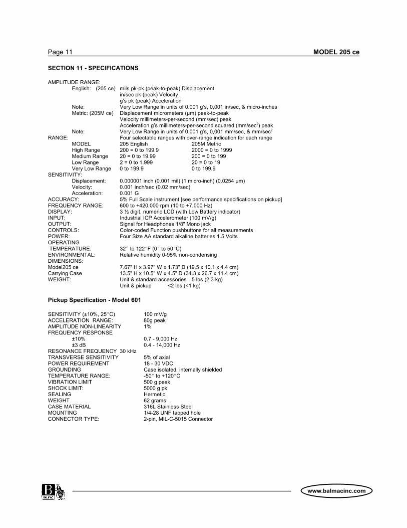
SECTION 11 - SPECIFICATIONS
AMPLITUDE RANGE:English: (205 ce) mils pk-pk (peak-to-peak) Displacement
in/sec pk (peak) Velocityg’s pk (peak) Acceleration
Note: Very Low Range in units of 0.001 g’s, 0,001 in/sec, & micro-inchesMetric: (205M ce) Displacement micrometers (µm) peak-to-peak
Velocity millimeters-per-second (mm/sec) peakAcceleration g’s millimeters-per-second squared (mm/sec2) peak
Note: Very Low Range in units of 0.001 g’s, 0,001 mm/sec, & mm/sec2
RANGE: Four selectable ranges with over-range indication for each rangeMODEL 205 English 205M MetricHigh Range 200 = 0 to 199.9 2000 = 0 to 1999Medium Range 20 = 0 to 19.99 200 = 0 to 199Low Range 2 = 0 to 1.999 20 = 0 to 19Very Low Range 0 to 199.9 0 to 199.9
SENSITIVITY:Displacement: 0.000001 inch (0.001 mil) (1 micro-inch) (0.0254 µm)Velocity: 0.001 inch/sec (0.02 mm/sec)Acceleration: 0.001 G
ACCURACY: 5% Full Scale instrument [see performance specifications on pickup]FREQUENCY RANGE: 600 to +420,000 rpm (10 to +7,000 Hz)DISPLAY: 3 ½ digit, numeric LCD (with Low Battery indicator)INPUT: Industrial ICP Accelerometer (100 mV/g)OUTPUT: Signal for Headphones 1/8" Mono jackCONTROLS: Color-coded Function pushbuttons for all measurementsPOWER: Four Size AA standard alkaline batteries 1.5 VoltsOPERATING TEMPERATURE: 32E to 122EF (0E to 50EC)ENVIRONMENTAL: Relative humidity 0-95% non-condensingDIMENSIONS:Model205 ce 7.67" H x 3.97" W x 1.73" D (19.5 x 10.1 x 4.4 cm)Carrying Case 13.5" H x 10.5" W x 4.5" D (34.3 x 26.7 x 11.4 cm)WEIGHT: Unit & standard accessories 5 lbs (2.3 kg)
Unit & pickup <2 lbs (<1 kg)
Pickup Specification - Model 601
SENSITIVITY (±10%, 25EC) 100 mV/gACCELERATION RANGE: 80g peakAMPLITUDE NON-LINEARITY 1%FREQUENCY RESPONSE
±10% 0.7 - 9,000 Hz±3 dB 0.4 - 14,000 Hz
RESONANCE FREQUENCY 30 kHzTRANSVERSE SENSITIVITY 5% of axialPOWER REQUIREMENT 18 - 30 VDCGROUNDING Case isolated, internally shieldedTEMPERATURE RANGE: -50E to +120ECVIBRATION LIMIT 500 g peakSHOCK LIMIT: 5000 g pkSEALING HermeticWEIGHT 62 gramsCASE MATERIAL 316L Stainless SteelMOUNTING 1/4-28 UNF tapped holeCONNECTOR TYPE: 2-pin, MIL-C-5015 Connector

For Complete Warranty and ServiceInformation and Terms of Sale,
please see our website atwww.balmacinc.com