model 2435 intelesite cell site environment control … manual sierra monitor corporation 1991 tarob...
TRANSCRIPT

APPLICABILITY & EFFECTIVITY
Effective for all Model 2435 Intelesite systems manufactured after January, 2005.
T10023
Rev. A
Model 2435 Intelesite C e l l S i t e E n v i r o n m e n t
C o n t r o l S y s t e m
Version 1.0
Sierra Monitor Corporation 1991 Tarob Court, Milpitas, CA 95035
(408) 262-6611 (800) 727-4377
(408) 262-9042 - Fax E-mail: [email protected] Web Site: www.sierramonitor.com
Instruction Manual

Instruction Manual
Sierra Monitor Corporation 1991 Tarob Court Milpitas, CA 95035 Phone: (408) 262 – 6611 Fax: (408) 262 – 9042
www.sierramonitor.com
THIS PAGE INTENTIONALLY LEFT BLANK

Instruction Manual
Sierra Monitor Corporation 1991 Tarob Court Milpitas, CA 95035 Phone: (408) 262 – 6611 Fax: (408) 262 – 9042
www.sierramonitor.com
Table of Contents
1 Product Description................................................................................................... 1
1.1 General ............................................................................................................................ 1 1.2 Control System Configuration......................................................................................... 2
1.2.1 Central Control Module (CCM) .............................................................................. 3 1.2.2 Remote HVAC Control Module (HCM) ................................................................. 4 1.2.3 Fan Control Module (FCM) .................................................................................... 4
2 Operation.................................................................................................................... 7 2.1 Introduction ..................................................................................................................... 7 2.2 Heat Management............................................................................................................ 7
2.2.1 Forced Air Primary Cooling .................................................................................... 7 2.2.2 HVAC Cooling........................................................................................................ 8 2.2.3 Site on Generator Power.......................................................................................... 9 2.2.4 Emergency Shutdown.............................................................................................. 9
2.3 DC Plant Management .................................................................................................... 9 2.3.1 Emergency Shutdown – High Temperature, External Command ......................... 10
2.4 Power Monitoring.......................................................................................................... 10 2.5 Front Panel Display and Keypad................................................................................... 10
2.5.1 Set Points Keys...................................................................................................... 12 2.5.2 Alarms Keys .......................................................................................................... 14 2.5.3 Controls Keys ........................................................................................................ 16 2.5.4 Plus and Minus Keys ............................................................................................. 18 2.5.5 Enter Key............................................................................................................... 18 2.5.6 Security PIN Codes ............................................................................................... 21
3 Sequence of Operation ............................................................................................ 23 3.1 Description .................................................................................................................... 23
4 Maintenance, Calibration and Service .................................................................. 31 4.1 Periodic Maintenance .................................................................................................... 31 4.2 Sensor Calibration ......................................................................................................... 31 4.3 Voltage Calibration ....................................................................................................... 31 4.4 Service ........................................................................................................................... 31
4.4.1 Alarm Diagnostics ................................................................................................. 32 4.4.2 System Management Functions – Diagnostics ...................................................... 33 4.4.3 Field Replacement Parts ........................................................................................ 33
5 Product Specifications............................................................................................. 33 6 Warranty .................................................................................................................. 34 7 Appendix A............................................................................................................... 36

Instruction Manual
Sierra Monitor Corporation 1991 Tarob Court Milpitas, CA 95035 Phone: (408) 262 – 6611 Fax: (408) 262 – 9042
www.sierramonitor.com
THIS PAGE INTENTIONALLY LEFT BLANK

Instruction Manual
Sierra Monitor Corporation 1991 Tarob Court Milpitas, CA 95035 Phone: (408) 262 – 6611 Fax: (408) 262 – 9042
www.sierramonitor.com Page 1 of 40
1 Product Description
1.1 General
The Model 2435 Intelesite Cell Site Environment Control System is designed to maximize EBTS (Enhanced Base Transceiver Station) site availability, reliability and energy efficiency through electronic, microprocessor based monitoring and management of the following functions and components:
Forced Air Primary Cooling
HVAC Systems
DC Power Plant
Generators
Specialized software is used to collect data from sensor inputs and make continuous, real time, control and alarm logic decisions. The results of the logic are used to operate control outputs, send alarms to the EAS (Environmental Alarm System) and display status and alarm conditions in the front panel display of the controller.
The Model 2435 Central Control Module replaces the conventional lead/lag controller for HVAC controls and augments the Rectifier Controller and iDEN Cell Site Controller to efficiently manage the DC Plant to maximize site availability during adverse conditions of high internal temperature or loss of commercial AC power.

Instruction Manual
Sierra Monitor Corporation 1991 Tarob Court Milpitas, CA 95035 Phone: (408) 262 – 6611 Fax: (408) 262 – 9042
www.sierramonitor.com Page 2 of 40
1.2 Control System Configuration
The Sequence of Operation that describes the executable logic to affect management of cell site functions and components is described in Section 3 of this manual. Major components are described here and are illustrated in Figure 1-1 System Block Diagram.
AC-1
Socket – Ethernet 1
HCMHCM
AC-2 AC-3
DCM
Socket – RS-232Socket – Ethernet 2
FCM
FanAssembly
IntakeAssembly
Utility VAC
Generator VAC
ATS Position
Outside Temperature
48 VDCPower Plant
CCM Central Control ModuleHCM HVAC Control ModuleFCM Fan Control ModuleDCM DC Control Module
Legend
Discrete AlarmsTo EAS
HCM
IO BUS2 X 20
TEMPRH CCM
Existing ConduitLoad Shed 1Load Shed 2
Load Shed 3DC Shunt Output 1DC Shunt Output 2
VDC Sense
Optional 48VDC Smoke
Optional ESD
System VDC
Fan VDC
Figure 1-1 System Block Diagram

Instruction Manual
Sierra Monitor Corporation 1991 Tarob Court Milpitas, CA 95035 Phone: (408) 262 – 6611 Fax: (408) 262 – 9042
www.sierramonitor.com Page 3 of 40
1.2.1 Central Control Module (CCM)
The control system provides continuous, automatic control of environmental conditions within the building. It manages the DC power plant under conditions of loss of commercial power or high temperature. It monitors fixed and portable generators and manages building HVAC systems accordingly.
All structure environment and power management controls are managed by the CCM firmware and distributed between functional modules via the serial Intelesite I/O Bus.
Direct connections to the CCM (Figure 1-2) include:
• Intelesite I/O Bus • Primary Internal Temperature
Sensor • Primary Internal Relative Humidity
Sensor • Outside Temperature Probe (OTP) • Site Occupied Status • AC Power Monitoring Inputs • DC Power Plant Monitoring and Controls Connections (To DCM) • EBTS EAS Connections • Three ProtoCessor Sockets for Serial or Ethernet Interface Options • Smoke Alarm/Emergency Shutdown (Optional)
The CCM is equipped with a backlit LCD display and keypad. The LCD display has two rows of twenty alphanumeric characters. All set point and configuration parameters may be viewed and changed through the front panel display and keypad. PIN code security is a user selectable option.
Three sockets are provided for ProtoCessor Communications Modules. These sockets allow Ethernet, RS-232 or RS-485 ProtoCessors to be installed.
These modules will allow the optional additional of the following features: • WebServer interface with DHCP server for operator interface • RS-232 craft port for menu operator interface • SNMP Traps to enable alarming through to the NOC, including store-and-
forward • Downloading of log files and event histories • Connection with intelligent generators for status monitoring • Connection with fire alarm systems • Connection with intelligent transfer switches (ATS) • Modem Connections
Figure 1-2 Model 2435 – CCM Central Control Module

Instruction Manual
Sierra Monitor Corporation 1991 Tarob Court Milpitas, CA 95035 Phone: (408) 262 – 6611 Fax: (408) 262 – 9042
www.sierramonitor.com Page 4 of 40
1.2.1.1 DC Load Shed Control Module (DCM)
In large EBTS sites which may or may not be equipped with generators, the DC plant is managed by the control system under conditions of loss of commercial AC power or high internal temperature. The DCM is contained within the CCM and monitors DC plant voltage. It contains three normally open control relays to manage external DC contactors. The relays close sequentially when voltage or temperature based load shedding is called for by the CCM. Total loss of power to the control system or control system failure causes the control relays to open.
The DCM also contains two normally open, control relays used by others to shunt-trip the main DC power feed to the site in the Shutdown on High Temperature or External Shutdown Command sequence.
1.2.2 Remote HVAC Control Module (HCM)
A powerful feature of the system is that physical HVAC control relays are now located in remote HVAC control modules which are installed adjacent to each air conditioner. Connection between the HCM (Figure 1-3) and the CCM is via the Intelesite I/O Bus. The controller firmware is designed to manage up to three HVAC systems.
An HCM is located at each HVAC unit. All control wiring connections are made at this module and the module is powered by the HVAC 24 VAC supply. Temperature control set points made at the CCM are automatically updated to the HCM. Each HCM is also equipped with a temperature sensor. In the event of CCM failure, control is automatically switched to the HCM’s, thus affording double redundant HVAC control.
1.2.3 Fan Control Module (FCM)
The FCM (Figure 1-4) is installed at the DC Exhaust Fan location and contains the fan control relay and processor to communicate with the CCM. The FCM also provides a fan status input which is a digital feedback signal directly from the DC motor. Failure of the status input to prove when the DC Exhaust Fan is called will cause the controller to generate a fan failure alarm.
1.2.3.1 DC Exhaust Fan System
The DC Exhaust Fan System is comprised of an intake assembly and an exhaust assembly. The intake assembly includes a weather hood with screen mounted on the exterior wall, intake louvers, and intake filter and frame assembly. The exhaust assembly includes the 48 VDC fan assembly, exhaust louvers and externally mounted weather hood with screen. The design is modularized to the largest extent possible to minimize installation time.
Figure 1-3 Model 2435 – HCM HVAC Control Module
Figure 1-4 Model 2435 – FCM Fan Control Module

Instruction Manual
Sierra Monitor Corporation 1991 Tarob Court Milpitas, CA 95035 Phone: (408) 262 – 6611 Fax: (408) 262 – 9042
www.sierramonitor.com Page 5 of 40
Figure 1-5 depicts a typical installation with a building wall thickness of 6”. The design, however, will accommodate various wall thicknesses in both concrete and lightweight buildings.
Figure 1-5 DC Exhaust Fan System Typical Installation

Instruction Manual
Sierra Monitor Corporation 1991 Tarob Court Milpitas, CA 95035 Phone: (408) 262 – 6611 Fax: (408) 262 – 9042
www.sierramonitor.com Page 6 of 40
THIS PAGE INTENTIONALLY LEFT BLANK

Instruction Manual
Sierra Monitor Corporation 1991 Tarob Court Milpitas, CA 95035 Phone: (408) 262 – 6611 Fax: (408) 262 – 9042
www.sierramonitor.com Page 7 of 40
2 Operation
2.1 Introduction
The Model 2435 Intelesite Cell Site Environment Control System provides continuous, automatic control of environmental conditions within the building; manages the DC power plant under conditions of high internal temperature or loss of commercial AC power, and monitors fixed and portable generators and manages building HVAC accordingly.
2.2 Heat Management
Forced air primary cooling is the principal method of cooling the building. If either the qualifying criteria for forced air cooling are not met or the internal temperature rises to the HVAC set point, air conditioning logic is implemented.
2.2.1 Forced Air Primary Cooling
Forced air primary cooling is accomplished using a DC exhaust fan system. Economizer algorithm criteria for forced air primary cooling are minimum internal temperature, maximum internal relative humidity and maximum external temperature, all of which are user adjustable. The internal temperature and relative humidity sensors are integral to the CCM. The external temperature sensor is installed outside of the building and wired to the CCM. Forced air primary cooling reduces energy consumption by minimizing HVAC usage and also enables cooling when on battery power. If the building is in a very dirty or dusty environment, forced air primary cooling may be disabled and air conditioning will be used.
The DC exhaust fan system is comprised of an intake assembly and an exhaust assembly. Figure 2-1 illustrates the intake assembly. The opening in the wall of the building measures 37” H x 15.5” W. This assures the required intake air to move air through the building and expel it through the 17.5” H x 17.5” W exhaust at a rate of 1,600 CFM.
The louver and hood assemblies are affixed to the exterior wall. The intake filter and frame assembly are affixed to the interior wall. The filter is a 30 ppi foam filter, UL 94 HF-1 certified for telecommunications equipment. The filter is supported in an aluminum frame with aluminum mesh on the exhaust side for strength. The filter does not require regular replacement; it may be easily removed, cleaned and reused.
Air FlowAir FlowAir Flow
Figure 2-1 Intake Assembly
Instruction Manual
Sierra Monitor Corporation 1991 Tarob Court Milpitas, CA 95035 Phone: (408) 262 – 6611 Fax: (408) 262 – 9042
www.sierramonitor.com Page 8 of 40
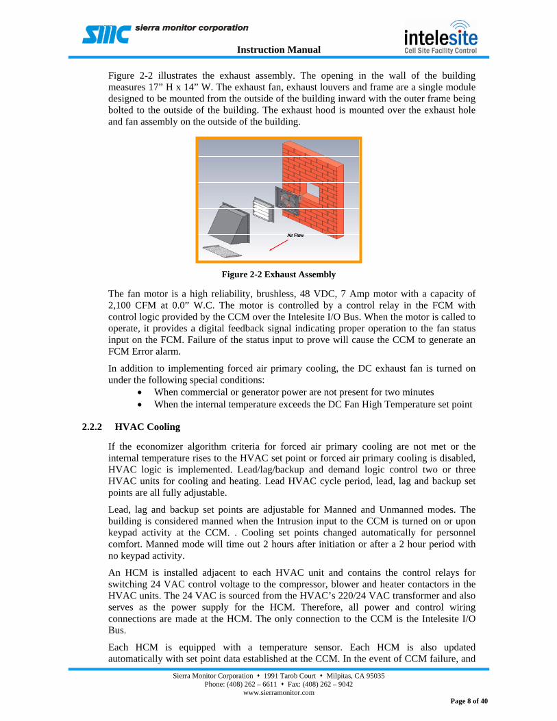
Figure 2-2 illustrates the exhaust assembly. The opening in the wall of the building measures 17” H x 14” W. The exhaust fan, exhaust louvers and frame are a single module designed to be mounted from the outside of the building inward with the outer frame being bolted to the outside of the building. The exhaust hood is mounted over the exhaust hole and fan assembly on the outside of the building.
The fan motor is a high reliability, brushless, 48 VDC, 7 Amp motor with a capacity of 2,100 CFM at 0.0” W.C. The motor is controlled by a control relay in the FCM with control logic provided by the CCM over the Intelesite I/O Bus. When the motor is called to operate, it provides a digital feedback signal indicating proper operation to the fan status input on the FCM. Failure of the status input to prove will cause the CCM to generate an FCM Error alarm.
In addition to implementing forced air primary cooling, the DC exhaust fan is turned on under the following special conditions:
• When commercial or generator power are not present for two minutes • When the internal temperature exceeds the DC Fan High Temperature set point
2.2.2 HVAC Cooling
If the economizer algorithm criteria for forced air primary cooling are not met or the internal temperature rises to the HVAC set point or forced air primary cooling is disabled, HVAC logic is implemented. Lead/lag/backup and demand logic control two or three HVAC units for cooling and heating. Lead HVAC cycle period, lead, lag and backup set points are all fully adjustable.
Lead, lag and backup set points are adjustable for Manned and Unmanned modes. The building is considered manned when the Intrusion input to the CCM is turned on or upon keypad activity at the CCM. . Cooling set points changed automatically for personnel comfort. Manned mode will time out 2 hours after initiation or after a 2 hour period with no keypad activity.
An HCM is installed adjacent to each HVAC unit and contains the control relays for switching 24 VAC control voltage to the compressor, blower and heater contactors in the HVAC units. The 24 VAC is sourced from the HVAC’s 220/24 VAC transformer and also serves as the power supply for the HCM. Therefore, all power and control wiring connections are made at the HCM. The only connection to the CCM is the Intelesite I/O Bus.
Each HCM is equipped with a temperature sensor. Each HCM is also updated automatically with set point data established at the CCM. In the event of CCM failure, and
Air FlowAir FlowAir Flow
Figure 2-2 Exhaust Assembly

Instruction Manual
Sierra Monitor Corporation 1991 Tarob Court Milpitas, CA 95035 Phone: (408) 262 – 6611 Fax: (408) 262 – 9042
www.sierramonitor.com Page 9 of 40
loss of the primary internal temperature sensor, control is automatically switched to the HCM’s. Therefore, the system affords double (triple with backup HVAC) redundant HVAC control.
2.2.3 Site on Generator Power
When the site is on generator power, there may be restrictions placed upon the use of HVAC units. The user may select at the CCM the maximum number of HVAC units that may operate simultaneously (0, 1, 2 or 3). If a single HVAC unit is selected for operation, the unit selected is user configurable at the CCM (1, 2, or 3). If zero is selected, this is indicative to the CCM that the generator is less than 12 KW in capacity.
2.2.4 Emergency Shutdown
The emergency shutdown sequences on high temperature, external command and detection of smoke require that the DC exhaust fan and all HVAC compressors, blowers and heaters be turned off immediately.
2.3 DC Plant Management
The rectifier controller is the primary manager of the DC plant. However, under conditions of a drop in DC bus voltage or excessive internal temperature, the Model 2435 CCM and DCM assume control of the DC plant. DC plant management logic is contained in the CCM and three normally open relays to manage external DC contactors are contained in the DCM. For purposes of managing heat generation and maximizing site run time, the DC electrical supply to RF racks is shed as a function of either voltage or temperature as follows:
Load Shed Level Base Radios Shed Set Point - Voltage Set Point - Temperature
1 Expansion 46 VDC 93 F 2 B Bus 45 VDC 96 F 3 A Bus 44 VDC 99 F
Table 2-1 Voltage or Temperature
If load has been shed as a function of voltage, reconnect will commence only when the controller senses the presence of AC power, either commercial or generator. If commercial power, load is reconnected sequentially, Levels 3, 2 and 1 when the voltage rises to the shed level plus a 2V hysteresis, with a minimum 30 second delay between levels. If generator power, load is reconnected sequentially, Levels 3, 2 and 1 when the voltage rises to the shed level plus a 2V hysteresis, with delays as follow:
Level 3: Generator on line after 1 minute delay
Level 2: Generator on line after 2 minute delay
Level 1: Generator >12 KW on line after 3 minute delay
If any level of load has been shed as a function of temperature, reconnect will commence only after expiration of the reconnect delay or if the CCM is manually restarted. Load is reconnected sequentially, Levels 3, 2 and 1 when the internal temperature drops to the respective shed level temperature less a 5° F hysteresis, with a minimum 30 second delay between levels.

Instruction Manual
Sierra Monitor Corporation 1991 Tarob Court Milpitas, CA 95035 Phone: (408) 262 – 6611 Fax: (408) 262 – 9042
www.sierramonitor.com Page 10 of 40
2.3.1 Emergency Shutdown – High Temperature, External Command
The emergency shutdown sequence on either high temperature or external command requires that the main DC power feed to the site be shunt-tripped. The DCM contains two normally open control relays to manage this function at the appropriate time in the sequence on command from the CCM.
2.4 Power Monitoring
The CCM is equipped with 3 digital inputs to monitor AC power to the site. Normally closed contacts from an automatic transfer switch will open to indicate the following conditions:
1. Utility power is lost 2. Emergency (generator) power is detected 3. Transfer switch set to receive power from the emergency bus
The control system uses this data to implement proper management of the following functions:
1. AC Power Fail alarm 2. HVAC utilization when on generator power 3. DC plant load reconnect
Details of the specific uses of this data in the executable logic are contained in Section 3, Sequence of Operation.
2.5 Front Panel Display and Keypad
The front panel display (Figure 2-3) is a backlit LCD, 2 rows x 20 characters. The keypad contains 6 tactile feedback pushbutton keys. Home display data are:
Inside Temp: Building internal temperature in degrees Fahrenheit. AUTO: Indicates that control logic is being implemented automatically by the controller in Unmanned mode. MANNED: Indicates that control logic is being implemented automatically by the controller in Manned mode. MANUAL: Indicates that manual controls have been selected via the front panel keypad and On/Off status of controls is selected manually. SHED: DC Plant Load Shedding sequence is in progress. Alarms #: Indicates the number of currently active alarms.
Figure 2-3 Model 2435 – CCM Front Panel Display Keypad

Instruction Manual
Sierra Monitor Corporation 1991 Tarob Court Milpitas, CA 95035 Phone: (408) 262 – 6611 Fax: (408) 262 – 9042
www.sierramonitor.com Page 11 of 40
Figure 2-4 Intelesite Primary Menu
Inside Temp 77.9FAUTO Alarms 0
Outside Temp -21.9%Inside RH 39%
Site Voltage51.2V
ATS PositionUtility
Controlssub menu
Set Pointssub menu
Alarmssub menu
System Managementsub menu
+
+
+
+
S
C
A
E
Intelesite – Primary Menu
Figure 2-4 illustrates in flow diagram form the Primary Menu and keypad entries to access desired data and functions. Pressing a key will cause requested data to be displayed and changes to variables may be made using the ( + ), ( - ) and ENTER keys. Following a change, the display will return to home data. Also, during keypad activity, if there is a period of inactivity of 45 seconds, the display will return to home data. Home data may also be returned immediately by pressing the CONTROLS key.

Instruction Manual
Sierra Monitor Corporation 1991 Tarob Court Milpitas, CA 95035 Phone: (408) 262 – 6611 Fax: (408) 262 – 9042
www.sierramonitor.com Page 12 of 40
2.5.1 Set Points Keys
Following are descriptions of the set points that may be displayed and changed. All temperatures are in degrees Fahrenheit. Also shown are factory default set points. Figure 2-5 illustrates the Set Points Sub-Menu in flow diagram form.
Set Point Name Description Default Unmanned HVAC
Set point temperature at which the controller will turn on the lead air conditioner when the building is unoccupied. The lag air conditioner will be turned on at a set point which is a fixed temperature delta above the lead set point. The backup air conditioner will be turned on at a set point which is the same temperature delta above the lag set point. The default temperature delta is 3 °F and may be modified in System Management Functions: System SP Modify.
77 oF
Manned HVAC Set point temperature at which the controller will turn on the lead air conditioner when the building is occupied. The lag air conditioner will be turned on at a set point which is a fixed temperature delta above the lead set point. The backup air conditioner will be turned on at a set point which is the same temperature delta above the lag set point. The default temperature delta is 3 °F and may be modified in System Management Functions: System SP Modify.
72 oF
DC Fan Cooling Minimum building internal temperature at which the controller will implement forced air primary cooling. This is one of three conditions which must be satisfied to implement this cooling mode. The other two are maximum external temperature and maximum internal relative humidity.
69 oF
DC Fan Hi Tmp Set point temperature at which forced air cooling is initiated regardless of economizer algorithm criteria or HVAC status.
85 °F
Heating Set point temperature at which the controller will turn on the lead heater. The lag heater will be turned on at a set point which is a fixed temperature delta below the lead set point. The backup heater will be turned on at a set point which is the same temperature delta below the lag set point. The default temperature delta is 3 °F and may be modified in System Management Functions: System SP Modify.
63 °F
RH Max: Maximum building internal relative humidity at which the controller will implement forced air primary cooling.
60%
Ext Tmp Max: Maximum external (outside air) temperature at which the controller will implement forced air primary cooling.
65 oF
Hi Tmp Alm Set point temperature at which the controller will generate a high temperature alarm. 90 oF
Low Tmp Alm Set point temperature at which the controller will generate a low temperature alarm. 45 oF
Hi Tmp Shtdn Set point temperature at which the controller will initiate the Emergency Shutdown on High Temperature sequence.
110 oF
Hi Humid Alm Set point relative humidity at which the controller will generate a high humidity alarm. 70% Load Shed V1 DC bus voltage at which the controller will shed Level 1 BR’s. -46 VDC Load Shed V2 DC bus voltage at which the controller will shed Level 2 BR’s. -45 VDC Load Shed V3 DC bus voltage at which the controller will shed Level 3 BR’s. -44 VDC Load Shed T1 Internal temperature at which the controller will shed Level 1 BR’s. 93 oF
Load Shed T2 Internal temperature at which the controller will shed Level 2 BR’s. 96 oF
Load Shed T3 Internal temperature at which the controller will shed Level 3 BR’s. 99 oF
Low DC Alarm: DC bus voltage at or below which the controller issues a DC Power Fail alarm. -43.2 VDC
Table 2-2 Set Points Descriptions

Instruction Manual
Sierra Monitor Corporation 1991 Tarob Court Milpitas, CA 95035 Phone: (408) 262 – 6611 Fax: (408) 262 – 9042
www.sierramonitor.com Page 13 of 40
Figure 2-5 Intelesite Set Points Sub-Menu
Inside Temp 77.9FAUTO Alarms 0
Manned HVAC 72F
Change SetpointUnmanned HVAC 77F
RH Max 60%
Set Point
+
+
Hi Tmp Alm 90F
Ext Tmp Max 65F
+
+
-
-
-
Lo Tmp Alm 45F
+
+
+
+
Load Shed V1 -46.0V
Hi Humid Alm 70%
Hi Tmp Shtdn 110F
Ld Shed V2 -45.0V
+
-
-
-
-
Modify SetpointUnmanned HVAC 77FE
Setpoint StoredUnmanned HVAC 75F
+/-E
Auto 5 seconds
Ld Shed V3 -44.0V
Load Shed T1 93F
-
-
Load Shed T3 99F
Load Shed T2 96F
Low DC Alarm -43.2V
+
+-
-
-
+
+
+
-
+
DC Fan Hi Tmp 85F
DC Fan Cooling 69F
Heating 63F
+
+
+
-
-
-
Same as Unmanned HVACExample above.
-
Intelesite – Set Points Sub-Menu

Instruction Manual
Sierra Monitor Corporation 1991 Tarob Court Milpitas, CA 95035 Phone: (408) 262 – 6611 Fax: (408) 262 – 9042
www.sierramonitor.com Page 14 of 40
2.5.2 Alarms Keys
Following are descriptions of the alarms that may be displayed. Next to the description of the alarm is the status: On or Off. Figure 2-6 illustrates the Alarms Sub-Menu in flow diagram form.
Alarm Name Description
High Temp Building internal temperature is greater than the High Temperature Alarm Set Point. Low Temp Building internal temperature is less than the Low Temperature Alarm Set Point. Intrusion The door of the structure has been opened and intrusion has not been acknowledged. Smoke Smoke alarm. Initiate the Emergency Shutdown on Detection of Smoke sequence. All
HVAC equipment and DC exhaust fan are turned off. DC Pwr Fail DC bus voltage has fallen below the Low DC Plant Voltage Alarm Set Point. HVAC1 Fail Air conditioner 1 has failed. Air conditioners 2 and 3 only are used for cooling. HVAC2 Fail Air conditioner 2 has failed. Air conditioners 1 and 3 only are used for cooling. HVAC3 Fail Air conditioner 3 has failed. Air conditioners 1 and 2 only are used for cooling. If all 3 air
conditioners have failed, Blowers 1, 2 and 3 and the DC exhaust fan are turned on. DC Fan Fail The DC exhaust fan has been called and the motor status input to the FCM has failed to
prove. High Humid Building internal relative humidity is greater than the High Humidity Alarm Set Point. Temp Probe Fail Signal output from the outside air temperature probe has fallen below a failure threshold
level. Int Temp Sens Fail Either internal temperature or internal relative humidity reading is outside permissible
limits: Temperature > 200° F or < -50 °F Relative Humidity > 100% or < 0%
Discovery Error The Discovery function has been completed and no HCM’s have been discovered on the Intelesite Bus.
AC Pwr Fail Commercial AC power is lost. Emer Pwr Detect Emergency power has been detected of the correct voltage and frequency.
Temp Shutdown Building internal temperature has reached the High Temperature Shutdown Set Point or Emergency Shutdown has been manually initiated through the external shutdown switch. The controller initiates the Emergency Shutdown on High Temperature or External Command sequence.
Emer Shutdown Emergency/High Temperature Shutdown Imminent alarm issued at 0.25 second intervals for a period of 5 seconds, following which Emergency Shutdown is initiated.
FCM Comms Fail A communications failure has occurred between the CCM and the FCM.
DCM Comms Fail A communications failure has occurred between the CCM and the DCM. DC Fan Fail The DC exhaust fan has been called and the motor status input to the FCM has failed to
prove. HCM Comms Fail A communications failure has occurred between the CCM and the HCM.
Table 2-3 Alarm Name Descriptions

Instruction Manual
Sierra Monitor Corporation 1991 Tarob Court Milpitas, CA 95035 Phone: (408) 262 – 6611 Fax: (408) 262 – 9042
www.sierramonitor.com Page 15 of 40
Figure 2-6 Intelesite Alarms Sub-Menu
Inside Temp 77.9FAUTO Alarms 0
Low Temp Off
Alarm statusHigh Temp Off
Intrusion Off
Alarms
+
DC Pwr Fail Off
Smoke Off
-
-
-
-
HVAC1 Fail Off
Discovery Error Off
IntTemp Sens Fail Off
Temp Probe Fail On
HVAC3 Fail Off
HVAC2 Fail Off
-
-
-
-
-
Auto 45 secs
Emer Pwer Detect Off
-
-
AC Pwr Fail Off
Temp Shutdown Off
-
Controls(typical)
Intelesite – Alarms Sub-Menu
+
+
+
+
+
+
+
+
+
+
+
+
Emer Shutdown Off
FCM Comms Fail Off
- +
+ -
-
DCM Comms Fail Off
- +
DC Fan Fail Off
HCM Comms Fail Off
- +
+ -
High Humid Off
+ -

Instruction Manual
Sierra Monitor Corporation 1991 Tarob Court Milpitas, CA 95035 Phone: (408) 262 – 6611 Fax: (408) 262 – 9042
www.sierramonitor.com Page 16 of 40
2.5.3 Controls Keys
Following are descriptions of the controls whose On/Off status may be viewed when in AUTO (Automatic) mode, or viewed and changed when in MANUAL mode. Figure 2-7 illustrates the Controls Sub-Menu in flow diagram form.
Control Description
DC Exhaust Fan DC Exhaust Fan Shunt Trip Close two control relays to shunt-trip main DC power feed HVAC1 Compressor Air Conditioner 1 Compressor HVAC2 Compressor Air Conditioner 2 Compressor HVAC3 Compressor Air Conditioner 3 Compressor HVAC1 Blower Blower 1 HVAC2 Blower Blower 2 HVAC3 Blower Blower 3 HVAC1 Heater Heater 1 HVAC2 Heater Heater 2 HVAC3 Heater Heater 3 DC Load Shed 1 Close Load Shed Level 1 control relay DC Load Shed 2 Close Load Shed Level 2 control relay DC Load Shed 3 Close Load Shed Level 3 control relay
Table 2-4 Controls Descriptions

Instruction Manual
Sierra Monitor Corporation 1991 Tarob Court Milpitas, CA 95035 Phone: (408) 262 – 6611 Fax: (408) 262 – 9042
www.sierramonitor.com Page 17 of 40
Figure 2-7 Intelesite Controls Sub-Menu
Inside Temp 77.9FAUTO Alarms 0
Control StatusDC Exhaust Fan Off
Controls
+ -
+
E
E Sel Control ModeAuto Control State
Shunt Trip ?
HVAC1 Compressor ?
HVAC3 Compressor ?
HVAC2 Compressor ?
-
-
-
HVAC1 Blower ?
HVAC3 Heater ?
HVAC2 Heater ?
HVAC1 Heater ?
HVAC3 Blower ?
HVAC2 Blower ?
-
-
-
-
-
DC Load Shed 2 ?
-
-
DC Load Shed 1 ?
DC Load Shed 3 ?
-
-
+
+
+
+
+
+
+
+
+
+
+
+
Sel Control ModeManual Control State
-
If AUTO Mode, View OnlyIf MANUAL Mode press Enter and Toggle using “+” or “-“If ? The device is not communicating
- +
Intelesite – Controls Sub-Menu
Control ModeMode AUTO
Instruction Manual
Sierra Monitor Corporation 1991 Tarob Court Milpitas, CA 95035 Phone: (408) 262 – 6611 Fax: (408) 262 – 9042
www.sierramonitor.com Page 18 of 40
2.5.4 Plus and Minus Keys
The (+) and (-) keys are used to scroll through set points, alarms, controls and system management functions and to increase/decrease values for changes.
2.5.5 Enter Key
The ENTER key is used to execute changes. It is also used to access System Management Functions. These are largely configuration functions which are set when initially commissioning the controller for operation. Following are descriptions of those functions. Figure 2-8 illustrates the System Management Sub-Menu in flow diagram form.
2.5.5.1 System Management Functions
Function Description Default Select HVAC Lead Select HVAC unit 1, 2 or 3 as the lead. 1
Lead Xchg Period Selects the lead exchange period, in days, from 0 to 30, during which the selected HVAC unit, 1, 2 or 3, will be called as the lead. At the expiration of the period, the next sequentially numbered HVAC unit will be called as the lead. If 0 is selected, lead exchange is disabled and the selected HVAC unit 1, 2 or 3, is the lead constantly.
7 Days
MANUAL Timeout Selects the MANUAL mode timeout period, in hours, from 1 to 24. If MANUAL mode is selected, when this period of time expires, the controller will revert to AUTO mode. This is a safeguard against controlled devices being turned on manually and inadvertently left to run indefinitely.
8 Hours
Short Cycle Delay Selects the short cycle delay, in minutes, from 1 to 5. When an air conditioner is turned off, this delay period commences. The air conditioner will not be called again until the expiration of the delay period to prevent compressor short cycling.
5 Minutes
ATS Switch This function is used to indicate to the controller the presence or absence of an automatic transfer switch at the site. 0 indicates present (Pres), 1 indicates absent (Abs). If present, the controller will monitor the normally closed contacts of the ATS for utility power, emergency power and ATS position.
0
Enable Ext Tmp Probe If the external (outside air) temperature probe is used, this function is enabled. If not, the function is disabled.
Enable
Enable Int RH If the relative humidity sensor is used, this function is enabled. If not, the function is disabled.
Enable
Sensor Calibration Enables calibration of the local (CCM) internal temperature sensor, external temperature probe, internal relative humidity sensor and the temperature sensors in each of the HCM’s. An offset is applied to match the reading of the sensor being calibrated to that of an independent, calibrated measurement device.
Set User PIN Enables entry of a factory programmed Master PIN, which in turn enables entry of a User PIN if password security is desired for making set point, AUTO/MANUAL and configuration changes. Security is discussed in Section 2.4 below.
0 0 0 0
Instruction Manual
Sierra Monitor Corporation 1991 Tarob Court Milpitas, CA 95035 Phone: (408) 262 – 6611 Fax: (408) 262 – 9042
www.sierramonitor.com Page 19 of 40
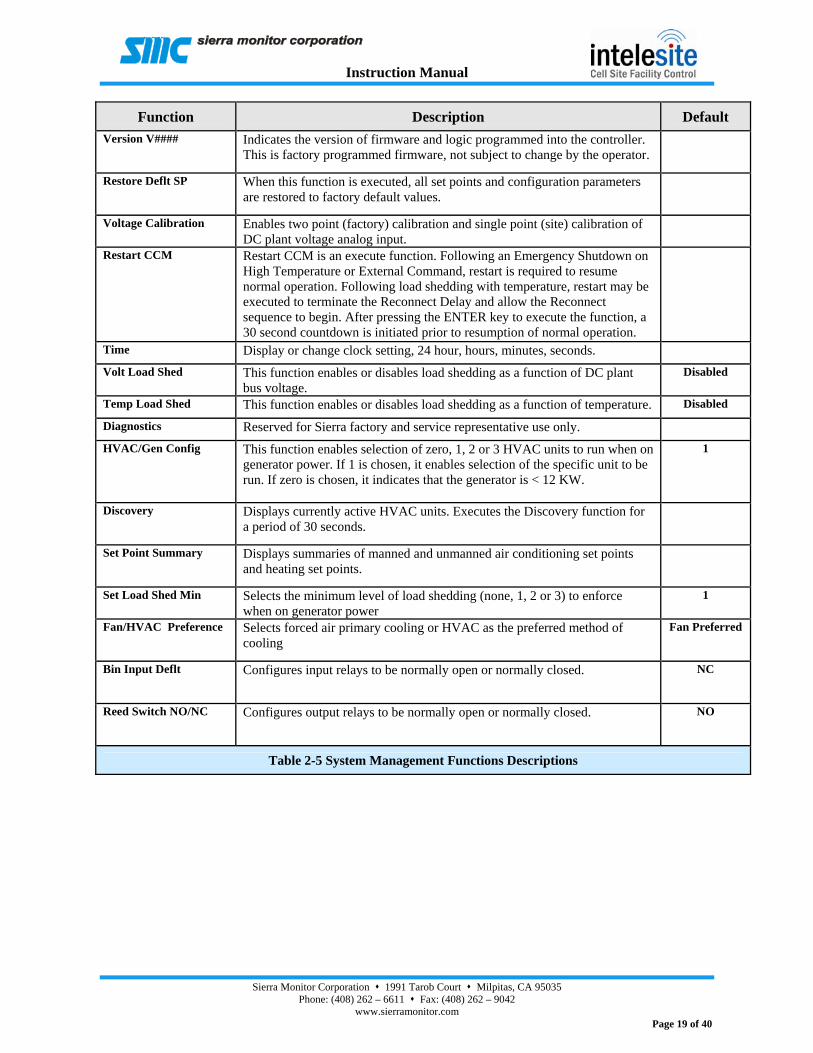
Function Description Default Version V#### Indicates the version of firmware and logic programmed into the controller.
This is factory programmed firmware, not subject to change by the operator.
Restore Deflt SP When this function is executed, all set points and configuration parameters are restored to factory default values.
Voltage Calibration Enables two point (factory) calibration and single point (site) calibration of DC plant voltage analog input.
Restart CCM Restart CCM is an execute function. Following an Emergency Shutdown on High Temperature or External Command, restart is required to resume normal operation. Following load shedding with temperature, restart may be executed to terminate the Reconnect Delay and allow the Reconnect sequence to begin. After pressing the ENTER key to execute the function, a 30 second countdown is initiated prior to resumption of normal operation.
Time Display or change clock setting, 24 hour, hours, minutes, seconds.
Volt Load Shed This function enables or disables load shedding as a function of DC plant bus voltage.
Disabled
Temp Load Shed This function enables or disables load shedding as a function of temperature. Disabled
Diagnostics Reserved for Sierra factory and service representative use only.
HVAC/Gen Config This function enables selection of zero, 1, 2 or 3 HVAC units to run when on generator power. If 1 is chosen, it enables selection of the specific unit to be run. If zero is chosen, it indicates that the generator is < 12 KW.
1
Discovery Displays currently active HVAC units. Executes the Discovery function for a period of 30 seconds.
Set Point Summary Displays summaries of manned and unmanned air conditioning set points and heating set points.
Set Load Shed Min Selects the minimum level of load shedding (none, 1, 2 or 3) to enforce when on generator power
1
Fan/HVAC Preference Selects forced air primary cooling or HVAC as the preferred method of cooling
Fan Preferred
Bin Input Deflt Configures input relays to be normally open or normally closed. NC
Reed Switch NO/NC Configures output relays to be normally open or normally closed. NO
Table 2-5 System Management Functions Descriptions

Instruction Manual
Sierra Monitor Corporation 1991 Tarob Court Milpitas, CA 95035 Phone: (408) 262 – 6611 Fax: (408) 262 – 9042
www.sierramonitor.com Page 20 of 40
Figure 2-8 Intelesite System Management Sub-Menu

Instruction Manual
Sierra Monitor Corporation 1991 Tarob Court Milpitas, CA 95035 Phone: (408) 262 – 6611 Fax: (408) 262 – 9042
www.sierramonitor.com Page 21 of 40
2.5.6 Security PIN Codes
The Intelesite system is factory configured for open access to all functions. The user has the option to enforce PIN code security to prevent unauthorized set point, AUTO/MANUAL status or configuration changes. To implement PIN code security:
1. Enter System Management Functions and scroll to Set User PIN. 2. Press the ENTER key and use the ( + ), ( - ) and ENTER keys to enter the Master PIN:
1 2 3 4. The Master PIN is factory programmed and cannot be changed. 3. Following entry of the Master PIN, a prompt is displayed to enter a User PIN. Enter a 4-
digit User PIN. The factory default User PIN is 0 0 0 0, which disables security protection. Entry of any other 4-digit PIN will automatically enforce security.
When security is enforced, initial keypad activity to make a set point change, AUTO/MANUAL status change or configuration change in system management functions will prompt a User PIN entry. When a valid PIN has been entered, it will remain in force until such time that there is no keypad activity for a period of 15 minutes. Thereafter, the PIN will have to be re-entered.

Instruction Manual
Sierra Monitor Corporation 1991 Tarob Court Milpitas, CA 95035 Phone: (408) 262 – 6611 Fax: (408) 262 – 9042
www.sierramonitor.com Page 22 of 40
THIS PAGE INTENTIONALLY LEFT BLANK

Instruction Manual
Sierra Monitor Corporation 1991 Tarob Court Milpitas, CA 95035 Phone: (408) 262 – 6611 Fax: (408) 262 – 9042
www.sierramonitor.com Page 23 of 40
3 Sequence of Operation
3.1 Description
The following tables describe the automatic sequence of operation of the Intelesite Model 2435 Cell Site Environment Control System. To operate to this sequence, the controller must be in AUTO mode of operation.
HVAC COOLING – MANNED MODE: Automatic control of 2 or 3 air conditioners using lead/lag/backup and demand logic when the building is occupied.
HVAC COOLING – UNMANNED MODE: Automatic control of 2 or 3 air conditioners using lead/lag/backup and demand logic when the building is not occupied.
HEATING: Automatic control of 2 or 3 heaters using lead/lag/backup and demand logic.
FORCED AIR PRIMARY COOLING: Automatic control of the DC exhaust fan for primary cooling under set point conditions of internal temperature, maximum external temperature and maximum internal relative humidity.
FORCED AIR COOLING – HIGH TEMPERATURE: Automatic control of the DC exhaust fan under conditions of building high temperature without the set point constraints of primary cooling.
EMERGENCY SHUTDOWN ON HIGH TEMPERATURE OR EXTERNAL COMMAND: Shutdown of all HVAC units and DC exhaust fan and shunt-trip main DC power feed. Controller Restart is required to resume normal operation.
EMERGENCY SHUTDOWN ON DETECTION OF SMOKE: Immediate shutdown of all HVAC units and DC exhaust fan.
DC PLANT LOAD SHEDDING – VOLTAGE: Automatic shedding of DC load as a function of decrease in DC bus voltage.
DC PLANT LOAD SHEDDING – TEMPERATURE: Automatic shedding of DC load as a function of building internal temperature.

Instruction Manual
Sierra Monitor Corporation 1991 Tarob Court Milpitas, CA 95035 Phone: (408) 262 – 6611 Fax: (408) 262 – 9042
www.sierramonitor.com Page 24 of 40
Control Description
Note: The site is considered manned when the system is triggered by the site occupied switch and/or keypad activity, with a 2 hour timeout.
Lead Compressor On
Lead Blower On
Calls Lead Compressor and Blower when internal temperature exceeds the Manned HVAC Set Point.
Lag Compressor On
Lag Blower On
Calls Lag Compressor and Blower if Lead Compressor is on and internal temperature increases by the Temperature Delta.
Backup Compressor On
Backup Blower On
Calls Backup Compressor and Blower if Lead and Lag Compressors are on and internal temperature increases by the Temperature Delta.
Note: In the sequence above, lead/lag/backup logic determines which air conditioner, 1, 2 or 3 is turned on first.
Compressors Off
Blowers Off
Compressors and blowers are turned off: 1. When internal temperature drops below the Manned HVAC Set Point
minus the Temperature Hysteresis. 2. In Emergency Shutdown on detection of smoke. 3. In Emergency Shutdown on high temperature or external command. 4. If Commercial Power Loss input is true, emergency power is detected
and ATS is on emergency power (Shut down none, 1, 2 or 3 units, user configurable).
Table 3-1 HVAC Cooling – Manned Mode
Control Description
Lead Compressor On
Lead Blower On
Calls Lead Compressor and Blower when internal temperature exceeds the Unmanned HVAC Set Point.
Lag Compressor On
Lag Blower On
Calls Lag Compressor and Blower if Lead Compressor is on and internal temperature increases by the Temperature Delta.
Backup Compressor On
Backup Blower On
Calls Backup Compressor and Blower if Lead and Lag Compressors are on and internal temperature increases by the Temperature Delta.
Note: In the sequence above, lead/lag/backup logic determines which air conditioner, 1, 2 or 3 is turned on first.
Compressors Off
Blowers Off
Compressors and blowers are turned off: 1. When internal temperature drops below the Unmanned HVAC Set Point
minus the Temperature Hysteresis. 2. In Emergency Shutdown on detection of smoke. 3. In Emergency Shutdown on high temperature or external command. 4. If Commercial Power Loss input is true, emergency power is detected
and ATS is on emergency power (Shut down none, 1, 2 or 3 units, user configurable).
Table 3-2 HVAC Cooling – Unmanned Mode

Instruction Manual
Sierra Monitor Corporation 1991 Tarob Court Milpitas, CA 95035 Phone: (408) 262 – 6611 Fax: (408) 262 – 9042
www.sierramonitor.com Page 25 of 40
Control Description
Lead Heater On
Lead Blower On
Calls Lead Heater and Blower when internal temperature drops below Heating Set Point.
Lag Heater On
Lag Blower On
Calls Lag Heater and Blower if Lead Heater is on and internal temperature decreases by the Temperature Delta.
Backup Heater On
Backup Blower On
Calls Backup Heater and Blower if Lead and Lag Heaters are on and internal temperature decreases by the Temperature Delta.
Note: In the sequence above, lead/lag/backup logic determines which heater, 1, 2 or 3 is turned on first.
Heaters Off
Blowers Off
Heaters and Blowers are turned off: 1. When internal temperature rises above the Heating Set Point plus the
Temperature Hysteresis. 2. In Emergency Shutdown on detection of smoke. 3. In Emergency Shutdown on high temperature or external command. 4. If Commercial Power Loss input is true, emergency power is detected
and ATS is on emergency power (Shut down none, 1, 2 or 3 units, user configurable).
Table 3-3 Heating
Control Description
DC Exhaust Fan On The DC Exhaust Fan is turned on when commercial or generator power are not present for 2 minutes or the following conditions exist: Internal Temperature >= DC Fan Cooling Set Point. External Temperature <=External Temperature Maximum Set Point. Internal Humidity <= RH Maximum Set Point.
DC Exhaust Fan Off The DC Exhaust Fan is turned off when commercial or generator power is restored and :
1. When internal temperature drops below DC Fan Cooling Set Point minus the Temperature Hysteresis.
2. If the external temperature rises above the External Temperature Maximum Set Point.
3. If the internal humidity rises above the RH Maximum Set Point. 4. If the internal temperature reaches the Manned or Unmanned Set Point,
as appropriate. 5. In Emergency Shutdown on detection of smoke. 6. In Emergency Shutdown on high temperature or external command.
Table 3-4 Forced Air Primary Cooling

Instruction Manual
Sierra Monitor Corporation 1991 Tarob Court Milpitas, CA 95035 Phone: (408) 262 – 6611 Fax: (408) 262 – 9042
www.sierramonitor.com Page 26 of 40
Control Description
DC Exhaust Fan On The DC Exhaust Fan is turned on when the internal temperature exceeds the DC Fan High Temperature Set Point.
DC Exhaust Fan Off The DC Exhaust Fan is turned off: 1. When the internal temperature drops below the DC Fan High
Temperature Set Point minus the Temperature Hysteresis. 2. In Emergency Shutdown on detection of smoke. 3. In Emergency Shutdown on high temperature or external command.
Table 3-5 Forced Air Cooling – High Temperature
Control Description
1. Emergency Shutdown has been requested by external shutdown switch or internal temperature has exceeded the High Temperature Shutdown Set Point.
2. Issue Emergency/High Temperature Shutdown Imminent Alarm at 0.25 second intervals for 5 seconds.
3. Immediately turn off all HVAC Blowers, Compressors, Heaters. 4. Immediately turn off DC Exhaust Fan. 5. After 5 seconds, close 2 control relays to shunt-trip main DC power
feed.
Blowers, Compressors, Heaters Off
DC Exhaust Fan Off
Main DC Power Off
Note: Following Emergency Shutdown, Controller restart is necessary to resume normal operation.
Table 3-6 Emergency Shutdown on High Temperature or External Command
Control Description
Blowers, Compressors, Heaters Off
DC Exhaust Fan Off
1. Emergency Shutdown has been activated by smoke detector alarm. 2. Immediately turn off all HVAC Blowers, Compressors, Heaters. 3. Immediately turn off DC Exhaust Fan.
Table 3-7 Emergency Shutdown on Detection of Smoke

Instruction Manual
Sierra Monitor Corporation 1991 Tarob Court Milpitas, CA 95035 Phone: (408) 262 – 6611 Fax: (408) 262 – 9042
www.sierramonitor.com Page 27 of 40
Control Description
This sequence is enabled under all conditions of site power: Commercial AC, Generator or Battery. It is not dependent upon the state of the Commercial Power Loss Input.
DC Load Shed Level 1 On Close control relay to shed DC load two (2) minutes (DC Load Shed Delay) after DC Plant voltage drops to and remains below Load Shed V1 Set Point.
DC Load Shed Level 2 On Close control relay to shed DC load two (2) minutes (DC Load Shed Delay) after DC Plant voltage drops to and remains below Load Shed V2 Set Point.
DC Load Shed Level 3 On Close control relay to shed DC load two (2) minutes (DC Load Shed Delay) after DC Plant voltage drops to and remains below Load Shed V3 Set Point.
DC Load Shed Level 3 Off 1. If commercial power on, open control relay to reconnect load when DC Plant voltage rises above Load Shed V3 Set Point plus Load Shed Hysteresis (V).
2. If generator power on, after 1 minute delay, open control relay to reconnect load when DC Plant voltage rises above Load Shed V3 Set Point plus Load Shed Hysteresis (V).
DC Load Shed Level 2 Off 1. If commercial power on, open control relay to reconnect load when DC Plant voltage rises above Load Shed V2 Set Point plus Load Shed Hysteresis (V).
2. If generator power on, after 2 minute delay, open control relay to reconnect load when DC Plant voltage rises above Load Shed V2 Set Point plus Load Shed Hysteresis (V).
DC Load Shed Level 1 Off 1. If commercial power on, open control relay to reconnect load when DC Plant voltage rises above Load Shed V1 Set Point plus Load Shed Hysteresis (V).
2. If generator power > 12 KW on, after 3 minute delay, open control relay to reconnect load when DC Plant voltage rises above Load Shed V1 Set Point plus Load Shed Hysteresis (V).
Note: 1. If commercial power on, load is reconnected sequentially, Levels 3, 2
and 1, with a 30 second delay between levels.
Table 3-8 DC Plant Load Shedding - Voltage

Instruction Manual
Sierra Monitor Corporation 1991 Tarob Court Milpitas, CA 95035 Phone: (408) 262 – 6611 Fax: (408) 262 – 9042
www.sierramonitor.com Page 28 of 40
Control Description
DC Load Shed Level 1 On 1. Close control relay to shed DC load two (2) minutes (DC Load Shed Delay) after Internal Temperature exceeds and remains above Load Shed T1 Set Point.
2. Initiate Reconnect Delay timer. DC Load Shed Level 2 On 1. Close control relay to shed DC load two (2) minutes (DC Load Shed
Delay) after Internal Temperature exceeds and remains above Load Shed T2 Set Point.
2. Reset and initiate Reconnect Delay timer. DC Load Shed Level 3 On 1. Close control relay to shed DC load two (2) minutes (DC Load Shed
Delay) after Internal Temperature exceeds and remains above Load Shed T3 Set Point.
2. Reset and initiate Reconnect Delay timer. DC Load Shed Level 3 Off Open control relay to reconnect load when Internal Temperature drops below
Load Shed T3 Set Point minus Load Shed Hysteresis (T). DC Load Shed Level 2 Off Open control relay to reconnect load when Internal Temperature drops below
Load Shed T2 Set Point minus Load Shed Hysteresis (T). DC Load Shed Level 1 Off Open control relay to reconnect load when Internal Temperature drops below
Load Shed T1 Set Point minus Load Shed Hysteresis (T). Notes:
1. Reconnect sequence begins only after expiration of Reconnect Delay or Controller Restart.
2. Load is reconnected sequentially, Levels 3, 2 and 1, with a 30 second delay between levels.
Table 3-9 DC Plant Load Shedding – Temperature

Instruction Manual
Sierra Monitor Corporation 1991 Tarob Court Milpitas, CA 95035 Phone: (408) 262 – 6611 Fax: (408) 262 – 9042
www.sierramonitor.com Page 29 of 40
Alarm Condition Description
High Temperature Building internal temperature is greater than the High Temperature Alarm Set Point.
Low Temperature Building internal temperature is less than the Low Temperature Alarm Set Point.
Intrusion The door of the structure has been opened and intrusion has not been acknowledged.
Smoke Smoke alarm. Initiate the Emergency Shutdown on Detection of Smoke sequence. All HVAC equipment and DC exhaust fan are turned off.
DC Power Fail DC bus voltage has fallen below the Low DC Plant Voltage Alarm Set Point. HVAC 1 Fail Air conditioner 1 has failed. Air conditioners 2 and 3 only are used for cooling. HVAC 2 Fail Air conditioner 2 has failed. Air conditioners 1 and 3 only are used for cooling.
HVAC 3 Fail Air conditioner 3 has failed. Air conditioners 1 and 2 only are used for cooling. If all 3 air conditioners have failed, Blowers 1, 2 and 3 and the DC exhaust fan are turned on.
High Humidity Building internal relative humidity is greater than the High Humidity Alarm Set Point.
Temperature Probe Fail Signal output from the outside air temperature probe has fallen below a failure threshold level.
Internal Temperature Sensor Fail The temperature sensor chip on the CCM failed.
Discovery Error No HCM’s are connected to the CCM AC Power Fail Commercial AC power is lost. Emergency Power Detected Emergency power has been detected of the correct voltage and frequency.
Temperature Shutdown
Building internal temperature has reached the High Temperature Shutdown Set Point or Emergency Shutdown has been manually initiated through the external shutdown switch. The controller initiates the Emergency Shutdown on High Temperature or External Command sequence.
Emergency/High Temperature Shutdown Imminent
Emergency/High Temperature Shutdown Imminent alarm is issued at 0.25 second intervals for a period of 5 seconds, following which Emergency Shutdown is initiated.
FCM Comms Fail Communication failure between FCM and CCM. DCM Comms Fail Communication failure between DCM and CCM. HCM Comms Fail Communication failure between HCM and CCM. Summary Alarm Common alarm to EAS indicating one or more system alarms are present. Control System Failure Control system has failed and automatically reverted to Fail-Safe state.
Table 3-10 Alarms

Instruction Manual
Sierra Monitor Corporation 1991 Tarob Court Milpitas, CA 95035 Phone: (408) 262 – 6611 Fax: (408) 262 – 9042
www.sierramonitor.com Page 30 of 40
THIS PAGE INTENTIONALLY LEFT BLANK

Instruction Manual
Sierra Monitor Corporation 1991 Tarob Court Milpitas, CA 95035 Phone: (408) 262 – 6611 Fax: (408) 262 – 9042
www.sierramonitor.com Page 31 of 40
4 Maintenance, Calibration and Service
4.1 Periodic Maintenance
The only periodic maintenance required of the Intelesite system is regular inspection of the CCM and HCM’s for dust or dirt build-up. The cover and base of the CCM enclosure and the cover of the HCM have vent slots to enable internal circulation of ambient air past the internal temperature and relative humidity sensors. The vent slots are located on vertical surfaces to minimize ingress of dust and dirt. When the HVAC system is shut down for service, it is recommended that power also be removed from the CCM. The front covers of the CCM and HCM’s should be removed to inspect for dust or dirt. Any build-up should be removed with a dry instrument such as compressed air or a small, dry paint brush.
4.2 Sensor Calibration
The system temperature and relative humidity sensors should be checked annually. This can be done by comparing their readings with those of an independent, calibrated measurement device. Agreement should be within +/- 1° F and +/- 2% RH. If calibration is required, the following procedure is used. 1. Enter System Management Functions and scroll to Sensor Calibration. 2. Press the ENTER key and scroll to the appropriate entry:
Int Sens Calib Ext Temp Site Calib Int RH Calib HCM Temp Calib 1 HCM Temp Calib 2 HCM Temp Calib 3
3. Press the ENTER key to display the current reading. Use the ( + ) key to apply positive offset to increase the reading to match that of the calibrated device. Increments are 1 °F and 1% RH. Use the ( - ) key to apply negative offset.
4. Press the ENTER key to store the data.
4.3 Voltage Calibration
The analog input circuitry measuring DC plant voltage should be checked annually. This can be done by comparing this reading with that of an independent, calibrated measurement device such as a digital volt meter. Agreement should be within +/- 0.1 VDC. If calibration is required, the following procedure is used.
1. Enter System Management Functions and scroll to Voltage Calibration. 2. Press the ENTER key and scroll to Site Calibration. 3. Press the ENTER key to display measured DC plant voltage. Use the ( + ) key to
apply positive offset to increase the reading to match that of the calibrated device. Use the ( - ) key to apply negative offset.
4. Press the ENTER key to store the data.
4.4 Service
The Intelesite system is fully modularized. Each module, CCM, FCM, DCM and HCM contains one printed circuit assembly (PCA). All PCA components are soldered. Therefore, field repairs are at the PCA level. To determine the nature and extent of any required

Instruction Manual
Sierra Monitor Corporation 1991 Tarob Court Milpitas, CA 95035 Phone: (408) 262 – 6611 Fax: (408) 262 – 9042
www.sierramonitor.com Page 32 of 40
repairs, two levels of diagnostics are available, Alarm Diagnostics and Diagnostics in System Management Functions.
4.4.1 Alarm Diagnostics
The following table describes system alarms which are automatically generated by the CCM’s self-diagnostics program. The table also describes appropriate diagnostic and corrective actions.
Alarm Name Diagnostic/Corrective Action
DC Fan Fail The DC exhaust fan has been called and the motor status input to the FCM has failed to prove. 1. If the motor is running, check continuity of the motor status input to the FCM. 2. Check that the motor status input is wired correctly to P4 on the FCM. 3. If the alarm continues to exist, consult Sierra Factory Service.
Temp Probe Fail Signal output from the outside air temperature probe has fallen below a failure threshold level. 1. Check that the wiring connection to TB 1 on the CCM is secure. See Figure A-1 in
Appendix. 2. Check that the jumpers J65 and J66are in the 1 and 2 positions, respectively, on the
CCM. 3. If alarm continues to exist, replace the Assembly, Temperature Sensor, Cable,
Adapter Int Tmp Sens Fail Either internal temperature or internal relative humidity reading is outside permissible limits:
Temperature > 200° F or < -50 °F Relative Humidity > 100% or < 0%
Replace Model SPK22122, Assembly, PCA, 2435-CCM Discovery Error The Discovery function has been completed and no HCM’s have been discovered on the
Intelesite Bus. 1. Check that the RS-485 connections between the CCM and HCM’s are secure. See
Figures A-1 and A-3 in the Appendix. 2. Check power to the HCM’s and that the Run LED’s on the HCM’s are flashing. If
not, replace Model SPK22124, Assembly, PCA, 2435-HCM as necessary. 3. Repeat the Discovery function. 4. If the alarm continues to exist, consult Sierra Factory Service.
FCM Comms Fail A communications failure has occurred between the CCM and the FCM. 1. Check that the RS-485 connections between the CCM and FCM are secure. See
Figures A-1 and A-4 in the Appendix. 2. Check power to the FCM and that the Run LED on the FCM is flashing. If not,
replace Model SPK22125 Assembly, PCA, Model 2435-FCM. 3. If the alarm continues to exist, consult Sierra Factory Service.
DCM Comms Fail A communications failure has occurred between the CCM and the DCM.
1. Check that the RS-485 connections between the CCM and DCM are secure. See Figures A-1 and A-2 in the Appendix.
2. Check power to the DCM and that the Run LED on the DCM is flashing. If not, replace Model SPK22123 Assembly, PCA, Model 2435-DCM.
3. If the alarm continues to exist, consult Sierra Factory Service. HCM Comms Fail A communications failure has occurred between the CCM and the HCM.
4. Check that the RS-485 connections between the CCM and HCM are secure. See Figures A-1 and A-3 in the Appendix.
5. Check power to the HCM and that the Run LED on the HCM is flashing. If not, replace Model SPK22124 Assembly, PCA, Model 2435-HCM.
If the alarm continues to exist, consult Sierra Factory Service.
Table 4-1 Alarm Diagnostics

Instruction Manual
Sierra Monitor Corporation 1991 Tarob Court Milpitas, CA 95035 Phone: (408) 262 – 6611 Fax: (408) 262 – 9042
www.sierramonitor.com Page 33 of 40
4.4.2 System Management Functions – Diagnostics
Corrective actions resulting from Alarm Diagnostics will generally return the system to full functionality. If, however, more comprehensive diagnostics are required, Diagnostics in System Management Functions must be used. This is a PIN code protected function. The PIN code is fixed and is independent of either the Master or User PIN codes optionally enforced for set point or configuration changes. This function is intended for use only by a Sierra Service Representative or by the user under the direction of a Sierra Service Representative.
4.4.3 Field Replacement Parts
The following parts may be replaced by the user in the field.
Sierra Part Number Description
2435-HCM PCA HVAC Control 2435 2435-OTP Outside Temperature Probe 2435-TSD Smoke Detector SPI22122 PCA Central Control Mod 2435 SPI22123 PCA DC Load Shed Mod 2435 SPI22125 PCA DC Fan Control Mod 2435 SPI49221 Fuse 1A Class G SPI49222 Fuse 10A Class G SPI69199 Filter for 2435-FAS
Table 4-2 List of Intelesite Spare Parts

Instruction Manual
Sierra Monitor Corporation 1991 Tarob Court Milpitas, CA 95035 Phone: (408) 262 – 6611 Fax: (408) 262 – 9042
www.sierramonitor.com Page 34 of 40
THIS PAGE INTENTIONALLY LEFT BLANK

Instruction Manual
Sierra Monitor Corporation 1991 Tarob Court Milpitas, CA 95035 Phone: (408) 262 – 6611 Fax: (408) 262 – 9042
www.sierramonitor.com Page 33 of 40
5 Product Specifications 2435-CCM Central Control Module
Power: 36 – 60 VDC, 30 mA at 48 VDC
Environmental: Temperature:
Operating Range: 4° to 120° F (-20° to 50° C) Storage Range: -22° F to 122° F (-30° to 50° C)
Humidity: 0 to 95% Non-Condensing
Front Panel: Display:
LCD Alphanumeric (2 Rows x 20 Characters) Front Panel Keypad
6 keys for Set Points, Alarms, Controls Serial, Ethernet Interface (Optional)
Up to 3 Ethernet, RS232 or RS485 ProtoCessors Integral Inputs
Temperature Relative Humidity
Digital Inputs: 11 External Alarm Inputs Smoke Alarm Intrusion Generator Power ATS Position Utility Power Spare (6)
Analog Input Outside Temperature (connect 2435-OTP)
Alarms: 4 Firmware Configurable 1 Watchdog
Enclosure Sheet Metal Plated, Painted Surface Mount Dimensions 14.6” x 14.1” x 3.0” (HWD)
2435-HCM HVAC Control Module Power:
24 VAC, 25 mA Integral Input:
Temperature Digital Inputs: 2
HVAC 1 Fail Spare (1)
Analog Input Connection for optional Proving Air Temperature Sensor
Control Outputs: 4 Compressor Blower Heater Spare
Enclosure Face plate mounted for installation on double gang box
2435-FCM Fan Control Module Power:
36 – 60 VDC, 24 mA at 48 VDC Digital Inputs: 2
Fan Motor Status
Spare Control Outputs: 3
Fan Motor Spare (2)
Enclosure Sheet Metal Plated, Painted Surface Mount Dimensions 10.1” x 8.4” x 3.1” (HWD)
2435-DCM DC Control Module Power:
36 – 60 VDC, 25 mA at 48 VDC Analog Inputs:..1
DC Plant Voltage Control Outputs: 5
Load Shed, N.O; 2A, 60 VDC (3) Main DC Shunt Trip, N.O; 2A, 60 VDC (2)
Enclosure Installed in 2435-CCM Enclosure
2435-TSD Smoke Detector Power:
5 – 8 VDC (supplied by 2435-CCM) Detectors:
Smoke - photoelectric Temperature Rate of Rise - Resistive
Alarm Output: One SPST dry contact (2 amp @ 30 VDC)
Audible Alarm: 68 db at 2900 Hz
Mounting Double gang box
Enclosure Dimension Diameter 6.125”, Height 2”
2435-OTP Outside Temperature Probe Connection:
Terminate on CCM Type:
Current - two terminal IC temperature transducer Temperature Range:
-55° F to 150° F Mounting
Wiring pull box type XX with ½” M-NPT Enclosure
Injection molded, white weather shield, Diameter 6”, Height 2”
2435-FAS Forced Air System Fan Assembly:
Cut-Out Dimension: 17.5” X 17.5” Rain Hood Dimension: 18” X 22” W x H Fan Motor: 48 VDC Fan Capacity: 1,600 CFM
Supply Air Assembly: Cut-Out Dimension: 15.5” X 37” Rain Hood Dimension: 20” X 41” W x H Filter Dimension: 15” X 37” Filter Type: Permanent, Cleanable filter media, Meets HF-1 of UL 94 Meant Time to Replace (MTTR): 5 minutes

Instruction Manual
Sierra Monitor Corporation 1991 Tarob Court Milpitas, CA 95035 Phone: (408) 262 – 6611 Fax: (408) 262 – 9042
www.sierramonitor.com Page 33 of 40
THIS PAGE INTENTIONALLY LEFT BLANK

Instruction Manual
Sierra Monitor Corporation 1991 Tarob Court Milpitas, CA 95035 Phone: (408) 262 – 6611 Fax: (408) 262 – 9042
www.sierramonitor.com Page 34 of 40
6 Warranty
SIERRA MONITOR CORPORATION warrants its environment controller products to be free from defects in workmanship or material under normal use and service for two years after date of shipment. SMC will repair or replace, without charge, any equipment found to be defective during the warranty period. Final determination of the nature and responsibility for defective or damaged equipment will be made by SMC personnel.
All warranties thereunder are contingent upon proper use in the application for which the product was intended and do not cover products which have been modified or repaired without SMC approval or which have been subjected to accident, improper maintenance, installation or application, or on which original identification marks have been removed or altered. This Limited Warranty also will not apply to interconnecting cables or wires, consumables (i.e. calibration gases, batteries), nor to any damage resulting from battery leakage.
In all cases SMC's responsibility and liability under this warranty shall be limited to the cost of the equipment. The purchaser must obtain shipping instructions for the prepaid return of any item under this warranty provision and compliance with such instruction shall be a condition of this warranty.
Except for the express warranty stated above, SMC disclaims all warranties with regard to the products sold hereunder including all implied warranties of merchantability and fitness and the express warranties stated herein are in lieu of all obligations or liabilities on the part of SMC for damages including but not limited to consequential damages arising out of/or in connection with the use or performance of the product.

Instruction Manual
Sierra Monitor Corporation 1991 Tarob Court Milpitas, CA 95035 Phone: (408) 262 – 6611 Fax: (408) 262 – 9042
www.sierramonitor.com Page 35 of 40
THIS PAGE INTENTIONALLY LEFT BLANK

Instruction Manual
Sierra Monitor Corporation 1991 Tarob Court Milpitas, CA 95035 Phone: (408) 262 – 6611 Fax: (408) 262 – 9042
www.sierramonitor.com Page 36 of 40
7 Appendix A
Figure 7-1 CCM Wiring Diagram

Instruction Manual
Sierra Monitor Corporation 1991 Tarob Court Milpitas, CA 95035 Phone: (408) 262 – 6611 Fax: (408) 262 – 9042
www.sierramonitor.com Page 37 of 40
Figure 7-2 FCM Wiring Diagram

Instruction Manual
Sierra Monitor Corporation 1991 Tarob Court Milpitas, CA 95035 Phone: (408) 262 – 6611 Fax: (408) 262 – 9042
www.sierramonitor.com Page 38 of 40
Figure 7-3 HCM Wiring Diagram

Instruction Manual
Sierra Monitor Corporation 1991 Tarob Court Milpitas, CA 95035 Phone: (408) 262 – 6611 Fax: (408) 262 – 9042
www.sierramonitor.com Page 39 of 40
Figure 7-4 OTP Wiring Diagram

Instruction Manual
Sierra Monitor Corporation 1991 Tarob Court Milpitas, CA 95035 Phone: (408) 262 – 6611 Fax: (408) 262 – 9042
www.sierramonitor.com Page 40 of 40
Figure 7-5 TSD Wiring Diagram