model 3210 series timer mb - raceamerica · 3 raceamerica model 3210 timer mb to the original...
TRANSCRIPT

Rev J
Model 3210 SeriesTimer MB
Mud Bog & ATVTiming System
Owner’s Manual
RaceAmerica Corporation105 Bonaventura DriveSan Jose, CA 95134(408) [email protected]
Copyright 2016 RaceAmerica Corporation.

2
RaceAmerica Model 3210 Timer MB
Table of Contents
LIMITED WARRANTY ........................................................................................................................3
THEORY OF OPERATION ..................................................................................................................4
PACKAGE COMPONENTS .................................................................................................................4POWER REQUIREMENTS ..................................................................................................................4AVAILABLE OPTIONS ........................................................................................................................4
PRODUCT SPECIFICATIONS .............................................................................................................4
SET-UP STEPS - 3210 SERIES ...........................................................................................................5 Track Diagrams ................................................................................................................................6 Power On/Self-Test ..........................................................................................................................9 SerialPortConfiguration .................................................................................................................9 RF Integrity ......................................................................................................................................9 Wireless Battery Level ...................................................................................................................10 Alignment Mode Hard Wired Sensors ..................................................................................................................10 T-Link Wireless Sensors ...........................................................................................................10 Configuration .................................................................................................................................11 ConfigurePrintHeader ..................................................................................................................11
TIMING A RUN ..................................................................................................................................11Timingarun ....................................................................................................................................11Abortarun ......................................................................................................................................11
KEYPAD FUNCTIONS ......................................................................................................................13
SYSTEM OPTIONS ............................................................................................................................14 Printing a Timeslip ..........................................................................................................................14 Adding a Scoreboard .......................................................................................................................14 PC Software ....................................................................................................................................14
MAINTENANCE ................................................................................................................................14
SPARE PARTS .....................................................................................................................................14
SUPPORT AGREEMENTS .................................................................................................................14
TIMESLIP HEADER CODES ............................................................................................................15TIMESLIP LAYOUT WORKSHEET .................................................................................................16
FOAM STAND ASSEMBLY ..............................................................................................................17
01/14/09

3
RaceAmerica Model 3210 Timer MB
TotheoriginalpurchaserofthisRaceAmericaproduct,RaceAmericawarrantsittobeingoodworkingorderforaperiodofninety(90)daysfromthedateofpurchasefromRaceAmericaoranauthorizedRaceAmericadistributor. Should this productmalfunctionduring thewarrantyperiod,RaceAmericawill,atitsoption,repairorreplaceitatnocharge,providedtheproducthasnotbeensubjectedtomisuse,abuse,oralterations,modifications,and/orrepairsnotauthorizedbyRaceAmerica.
AnyproductrequiringLimitedWarrantyserviceduringthewarrantyperiodshouldbereturnedtoRaceAmericawithproofofpurchase.Ifreturnofmerchandiseisbymail,thecustomeragreestoinsuretheproduct,prepayshippingcharges,andshiptheproducttoRaceAmerica,Inc.,
ALL EXPRESSED AND IMPLIED WARRANTIES FOR THIS PRODUCT ARE LIMITED IN DURATION TO THE ABOVE NINETY DAY PERIOD.
UNDER NO CIRCUMSTANCES WILL RACEAMERICA BE LIABLE TO THE USER FOR DAMAGES, INCLUDINGANYLOSTPROFITS,LOSTSAVINGS,OROTHER INCIDENTALORCONSEQUENTIALDAMAGESARISINGOUTOFTHEUSEOF,ORINABILITYTOUSE,SUCH PRODUCT.
THISWARRANTYGIVESYOUSPECIFICLEGALRIGHTS,ANDYOUMAYALSOHAVEOTHER RIGHTS WHICH MAY VARY FROM STATE TO STATE.

4
RaceAmerica Model 3210 Timer MB
THEORY OF OPERATION
The 3210 Series Timers are completely self-contained race timing systems made with thelatesttechnologyCMOScircuitcomponentstoprovideahighlyaccuratetimingsolution.Thesystemcontainsaninternalquartzcrystalclocktomaintaintimeaccuracyanddisplayofraceresultstoonethousandthofasecond.
Powerissuppliedtothetimerconsoleandtrack sensor components of the 3210 by the 12VDC automotive battery connected to theREDandBLACKalligatorclips,cigarettelighteradapter,oranACadapter.Anabsoluteminimumof11.0VDCisrequiredforreliableoperationofthe system. Under normal conditions, chargedbatteries will operate for several days of racing withoutrequiringarecharge.
The Beam Emitters and Track Sensors operateoninvisible(totheunaidedhumaneye)InfraRed(IR)light.ThecodedlightfrequenciesareconstantlyreceivedbytheTrackSensorsuntila car interrupts reception (‘breaks’ the beam).Connections to the console can be hard wired or wirelessly connected via T-Link track electronics.
The IR Beam Emitter to Track Sensor transmission operates on Line-of-Sight principles. Thismakesalignmentoftheseunitscritical.Tipsare provided to aid alignment on surfaces thatare other than ideal. These unitswill operateoverawiderangeofconditionsbutshouldnotbeoperatedbeyondthespecificationparameters(lessthan 4 ft or more than 50 ft).
Once the system is properly set up andalignedontheracingsurface,thetimerconsolewill‘monitor’thetracksensorseachtimearunis made.
PACKAGE COMPONENTS
The Timer MB is sold in hard wire versions (3210D),wirelessversions(3210D-W)andwithslower response IR beams (3210DS and 3210DS-Wwith‘58’beams).
Each 3210 Series Timer MB hard wired
timingsystempackageincludes: 1 - 3210D/3210DS Console Unit2-IRBeamEmittersModel5040/50582-IRTrackSensorsModel5140/5158 1 - Cable Assembly for Track Sensors 1 - 12VDC Power Patch Cord1-OwnersManual
Each 3210 Series Timer MB wireless timing withexternalsensorssystempackageincludes:
1 - 3210D-W/3210DS-W Console Unitwith5801T-Linkconsolemodule2-5800T-Linkunits(IDsA/B)2-05-5825T-LinktoSensorcable2-IRBeamEmittersModel5040/50582-IRTrackSensorsModel5140/51582-5890T-Linkbatterychargers 1 - 12VDC Power Patch Cord1-OwnersManual
Each 3210 Series Timer MB wireless timing withinternalsensorsystempackageincludes:
1 - 3210D-W/3210DS-W Console Unitwith5801T-Linkconsolemodule2-5805/5808T-Linkunits(IDsA/B)2-IRBeamEmittersModel5040/50582-5890T-Linkbatterychargers 1 - 12VDC Power Patch Cord1-OwnersManual
NOTE:SensorsandEmittersworkinpairs;5040 emitters work with 5140 sensors and slow response5058emittersworkwith5158sensors.Do not mix sensor pairings!
POWER REQUIREMENTS
Youwill need these additional items tooperateyour3210Seriestimingsystem:
1-12VDCautobatteryforConsole8-‘AA’batteriesforBeamEmitters
NOTE:Operatingthetimerfromabatteryconnectedtoachargerorrunningcarenginewillresult in anovervoltageconditionanddamagethe timer.
Model 3210 AVAILABLE OPTIONS

5
RaceAmerica Model 3210 Timer MB
andtheModel5140/5158IRTrackSensorsareplaced on the track opposite the similar Emitters. The Track Sensor Cable is keyed to match the Start and Finish track sensor positions as marked at the end of the cable (see cable diagram).
NOTE:SensorsandEmittersworkinpairs;5040 emitters work with 5140 sensors and slow response5058emittersworkwith5158sensors.Do not mix sensor pairings!
STEP 2 - Identify the emitter/sensor placements on
thetrack.Thelanewidthshouldbesetbetweenfour(4)andfifty(50)feet.Tohelpindetermininginitial Beam Emitter to Track Sensor alignment in largertrackwidths,useastringstretchedbetweenthe beam emitter and track sensor or eyeball a straightlinebetweenunits.
STEP 3 -
Model5140/5158-IRTrackSensor
Note cable connector is located in the side facing away from the track. Track Sensors are interchangeable with similar models. Track Sensorispicturedbothtopandbottomsidesup.
Model5040/5058-IRBeamEmitter
NoteOn/OffswitchandplacementforfourAAbatteries for each Beam Emitter. Beam Emitters areinterchangeablewithsimilarmodels.Pictureshowstopandbottomofunits.
5801T-LinkWireless(ontimermodule)5808T-LinkWirelessSensor(req5058)06-TL01 T-Link to PC Cable06-TT01 T-Link to Timer Cable 10 ft06-TT02 T-Link to Timer Cable 25 ft06-58AX-T-LinkIDreconfigurekit4500BDataCommunicationPOD (for printers and displays >100ftfromconsole-2req’d)4520AWirelessRFDataLink(2req’d)6070B Carry/Storage Case 6502A AC Power Adapter6460/6560/6650/6860ETDisplayBrds3121ADataCaptureSoftwareforPCs5050/5078-ExtendedrangeEmitter-75ft7540 - Foam Stands for Sensors/Emitters
PRODUCT SPECIFICATIONS
The following listing provides the designed performancespecificationsforthe3210ESeriestimingsystems:
Lane Width 4 to 50 feetETCapacity upto999.999secTimeAccuracy 0.001seconds Timer to Start* 100 feet Start to Finish* 200 feet
*Wirelessallowsgreaterdistances;several other wired cable lengths available.
SET-UP STEPS - 3210 SERIES
STEP 1 - Familiarize yourselfwith the components
picturedinthismanualandhowtheyinterconnect.TheTrackSensorCableisconfiguredforconnec-tion between the a Sensors and Timer Console.
All connectors are keyed for proper orienta-tion. The 12VDC battery is connected with the REDalligatorcliptoplus(+)terminalofthebat-tery and the BLACK alligator clip to (-) terminal of the battery.
The free standing, battery poweredModel5040/5058IRBeamEmittersareplacedon theonesideofthetrackatthestartandfinishlines

6
RaceAmerica Model 3210 Timer MB
Fig 2 - T-Link wireless with external Track Sensors
Fig 1 - Hard-wired Track Sensors

7
RaceAmerica Model 3210 Timer MB
Fig 4 - Underside cable connections for Timer MBHard wire and wireless sensors cannot be mixed!
T-Link mountedon underside forwireless operation
Model5801
Hard wire cable connector
12VDC Power inputplug
Fig 3 - T-Link wireless with internal Track Sensors and T-Link ‘Z’unitmountedunderTimerconsole. Antennaextensioncablesandmountingbracketsareavailableifrequired.

8
RaceAmerica Model 3210 Timer MB
Fig6-HardwiredDigitalDisplaysutilizingCommunicationPODsfor5”/8”displays;15”/24”displayshaveinternalPODs
Connecting System Options
Fig 5 - RS232 Hard wired Digital Display and/or PC Limited to 100ft cable lengths
Fig7-Wirelessdisplaysallowfullflexibility

9
RaceAmerica Model 3210 Timer MB
LayouttheTrackSensorCablesonthetracksite(seecablediagramFig1).Thelargeroundconnector connects to the Console and the two smaller connectors (RJ12) connect to the Track Sensors at the Start and Finish lines as indicated on the cable near the RJ12 connector. Install the Emitter and Sensors in the Foam Stands (if this optionwaspurchased);connecttheCabletotheTimerConsoleandtheTrackSensors(throughtheopening in the back of the Foam Stand).
IfT-Linkwirelessunitsensors(externalorinternal)arebeingused,Placethe‘A’unitattheStartandthe‘B’unitattheFinishperdiagrams(Fig2or3).Placethe‘Z’unitintheproximityof the console and connect to the Serial Port (Bluecable06-TT01or06-TT02).The‘Z’unitmayactuallybemountedunderneaththeconsole(Model 5801). Positioning the antenna(s) ashigh in the air as possible and with line-of-sight betweenunitswilloptimizeperformance.Withthe under side unit, connect the short cablebetween the T-Link and serial port (Fig 4).
STEP 4 -
Connectanyoptionalscoreboards,displaysor PCs per ownermanuals at this time. Thedrawings in Figs 5 thru 7 show some of theconnection options.
Connections are for RS232 serial data at 9600baud.Whentheoptionislocatedmorethan100ftfromtheconsole,usingwirelessorRS422communicationPODswillaccomplishthetask.
STEP 5 -
ConnecttheRED(+)andBLACK(-)alliga-torclipstothe12VDCbatteryandyou’rereadytobegin;use theACAdapter if theoptionwaspurchased.Plugintheroundplugintothepowerconnectorontheundersideofthetimerconsole.
POWER ON/SELF-TEST
Connectingthe12VDCsourcetotheSystemConsole places the RaceAmerica 3210 Series Tim-erintoaself-testofthemicroprocessorcircuitryand the LED (Light Emitting Diode) display. This isaninternaltestaswellasavisualcheckoftheLED display. The LED Displays progressively sequence thedigit ‘8’ througheachsegmentofalldigitsandthenprogressivelyturnsthemoff;finally,thedisplayshowstheproductmodelnum-ber and code revision [ 3210 ] [d00.0] contained withinthemicroprocessorintheupperandlowerdisplays respectively (example only).
Thetimerautorecognizeswhetherthetimerisconfiguredforhardwiredorwirelesssensorsand enables appropriate functioins. Both startandfinishmustoperateinthesameconfiguration.
Afterpower-up,checksensoralignmentandmake any configuration changes to the defaultsettingsbeforetimingarun.
SERIAL PORT CONFIGURATIONS
Fig8-InfraredBeamAlignment-TheEmitterthrowsaspotlightlikebeamofinfraredlight;theSensorshouldbealignednearthecenterofthebeamforoptimalreceptionandalignment.
Sensor Emitter
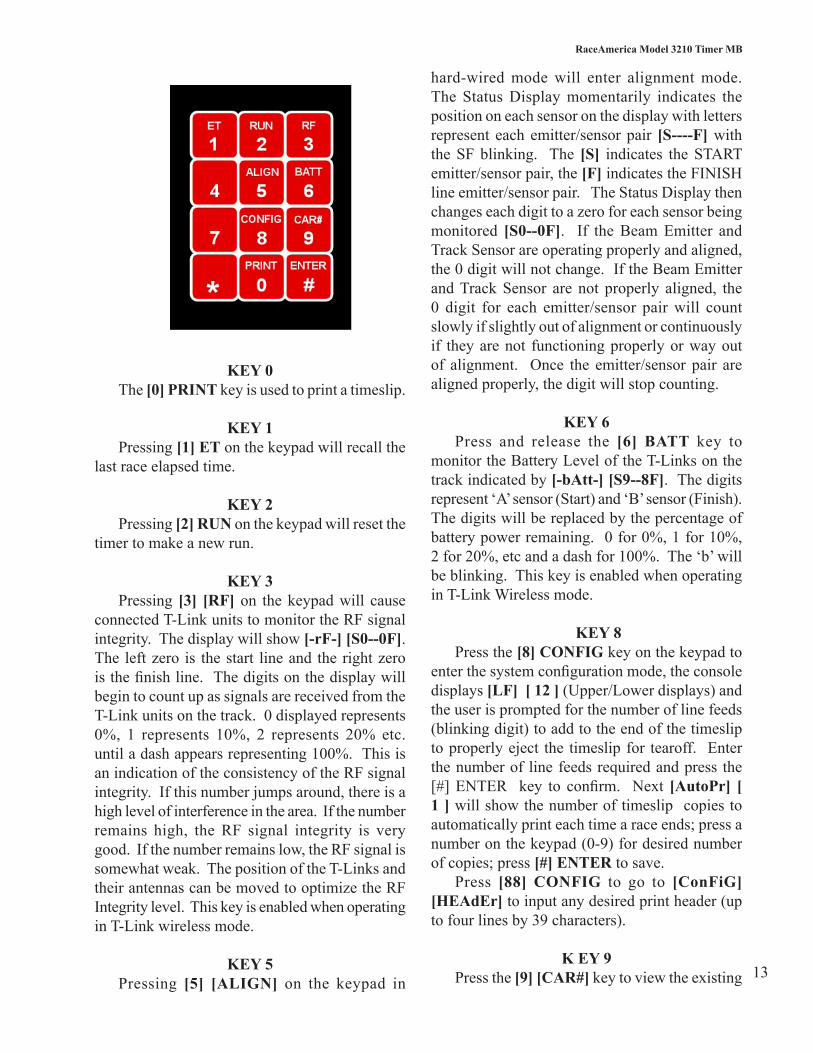
Fig 9 - Timer MB Keypad

10
RaceAmerica Model 3210 Timer MB
TheRS232SerialPortcanbeconfiguredforT-Link Wireless Track Sensors or to interface to a PCrunningracemanagementsoftware.
The Serial Port is enabled for two way communications(inforT-Linkdata,outforPCsand displays. The Display port is also a serial port and transmits data in Chronomix format.
NOTE:WhenconnectingtotheSerialPort,thePCordisplaymustbeconfiguredat9600baud,8 data bits, noparity, 1 stopbit, nohandshake(9600/8/N/1).
RF INTEGRITY
When operating the Timer MB with T-Link wireless sensors, theRadio Frequency Signalintegrity can be monitored. Pressing [3] RF on thekeypadwillcauseconnectedT-Linkunitstomonitor the RF signal integrity. The display will show [--rF--] [S----F].Theleftdashisthe‘A’(startline)unitandtherightdashisthe‘B’(finishline)unit.ThedashesonthedisplaywillbegintocountupassignalsarereceivedfromtheT-Linkunitsonthetrack[--rF--] [S0--0F]. 0 displayed represents 0%, 1 represents 10%, 2 represents20%etc.untiladashappearsrepresenting100%.This is an indication of the consistency of the RFintegrity.Ifthisnumberjumpsaround,thereis a high level of interference in the area. If the number remainshigh, theRFsignal strength isverygood. If thenumber remains low, theRFintegrity is somewhatweakdue to thedistancefromthe’Z’unitorathereisacontinuouslevelof RF interference. The position of the T-Links andtheirantennasshouldbemovedtooptimizethe RF Integrity level. High gain antennas can be usedtoincreaseRFIntegrity.
WIRELESS BATTERY LEVEL
When operating the Timer MB with T-Link Wireless sensors, The battery level of eachwireless link unit can bemonitored from theconsole. Press and release the [6] BATT key to monitor the Battery Level of the T-Links on the
track indicated by [tbAtt-] [S0--0F]. The dashes represent‘A’sensor(Start)and‘B’sensor(Finish).The dashes will be replaced by the percentage of batterypowerremaining.0for0%,1for10%,2for20%,etcandadashfor100%.Anyreadingabove 40% should be adequate for hours ofoperation.
ALIGNMENT MODE
Hard Wired Sensor Alignment -To verify hard wired Track Sensors are
properlyalignedwiththeirBeamEmitters,selectthe hard wired Alignment Mode by pressing the [5] ALIGNkeyontheKeypad.TheStatusDisplaymomentarily indicates the position on each sensor on the display with letters represent each emitter/sensor pair [S----F] with the SF blinking. The [S]indicatestheSTARTemitter/sensorpair,the[F] indicates the FINISH line emitter/sensor pair. TheStatusDisplaythenchangeseachdigittoazeroforeachsensorbeingmonitored[S0--0F]. If the Beam Emitter and Track Sensor are operating properlyandaligned,the0digitwillnotchange.If the Beam Emitter and Track Sensor are not properlyaligned,the0digitforeachemitter/sensorpairwillcountslowlyifslightlyoutofalignmentor continuously if they are not functioningproperly orway out of alignment. Once theemitter/sensorpairarealignedproperly,thedigitwillstopcounting.Ifthealignmentisoffalittleor intermittent, the digit for that emitter/sensorpairwillcountwhentheyfloatoutofalignment.Remember,theBeamEmittersandTrackSensorsoperate on a ‘Line-of-Sight’ concept andmayrequireshimsiftheyareinstalledonastreetwithacrown.Leaves,people,andotherdebriswillalsobreakthebeamsandcouldgivefalsesignals,sokeep everyone and everything clear of the Beam EmittersandTrackSensorduringracingactivity.
Tomaximize thealignmentof theemitter/sensor pairs, it is suggested to rotate theBeamEmitterslowlyleftandrightuntilthealignmentforthatpairbeginstocount.Thistechniquewilldeterminethemaximumlateraldetectionangle.RotatingtheBeamEmitterupanddownuntilthealignmentstartscountingdeterminesthemaximum
11
RaceAmerica Model 3210 Timer MB
vertical detection angle. Once these extremes are established,positiontheBeamEmitterinthecen-teroftheleft/rightdetectionangleandup/downdetection angle. Repeat this same process with the other Beam Emitter and both Track Sensors. Thiswillmaximizethealignmentaccuracy.Pressthe [#] ENTER key to exit Alignment Mode. It shouldalsobenotedthatoncethezerodigithasstartedcounting,itwillneverstopatzeroagainunlessAlignmentModeisexitedandreentered.This can be helpful for leaving the system inalignment mode for an extended period of time to check on an intermittent condition.
T-Link Alignment - Proper alignment can be determined by observing the Left LED on the T-Link connected to the sensor (or with an internal sensor). When theLEDisblinkingslowly,theemitterandsensorarealigned;whentheLEDisONsolid,thesensoris not properly aligned. Use the same alignment technique discussed for hardwired sensors toattain correct alignment while monitoring the LED status.DothisforboththeStartandFinishsensor.
CONFIGURATION
The MB Timer ships with the following factorydefaultsettings:
Print Line Feeds 10AutoPrintTimeslip 1
Ifanyofthesesettingsneedtobechanged,press the [8] CONFIG key on the Keypad to enter thesystemconfigurationmode,theconsoledis-plays [ConFiG] [Print] (Upper/Lower displays), press [#] ENTER to enter printer details. [LF] [10] andtheuserispromptedforthenumberofline feeds (blinking digit) to add to the end of the timesliptoproperlyejectthetimeslipfortearoff.Enterthenumberoflinefeedsrequiredandpressthe [#] ENTER key toconfirm. Next [Auto-Pr] [1] willshowthenumberoftimeslipcopiestoautomaticallyprinteachtimearaceends;pressanumberonthekeypad(0-9)fordesirednumberofcopies;press[#] ENTER to save.
CONFIGURE PRINT HEADER
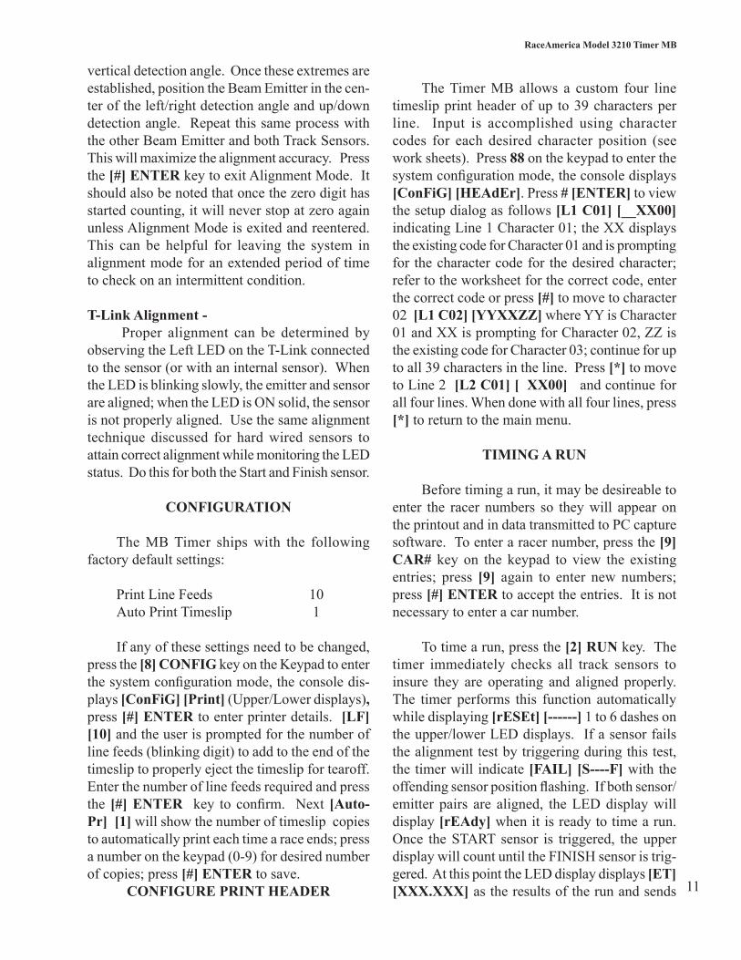
TheTimerMBallows a custom four linetimeslipprintheaderofup to39charactersperline. Input is accomplished using charactercodes for each desired character position (see work sheets). Press 88 on the keypad to enter the systemconfigurationmode,theconsoledisplays[ConFiG] [HEAdEr]. Press # [ENTER] to view thesetupdialogasfollows[L1 C01] [__XX00] indicatingLine1Character01;theXXdisplaysthe existing code for Character 01 and is prompting forthecharactercodeforthedesiredcharacter;refertotheworksheetforthecorrectcode,enterthe correct code or press [#] to move to character 02 [L1 C02] [YYXXZZ] where YY is Character 01andXXispromptingforCharacter02,ZZistheexistingcodeforCharacter03;continueforupto all 39 characters in the line. Press [*] to move to Line 2 [L2 C01] [ XX00]andcontinueforallfourlines.Whendonewithallfourlines,press[*]toreturntothemainmenu.
TIMING A RUN
Beforetimingarun,itmaybedesireabletoenter the racer numbers so theywill appear ontheprintoutandindatatransmittedtoPCcapturesoftware.Toenteraracernumber,pressthe[9] CAR# key on the keypad to view the existing entries; press [9] again to enter newnumbers;press [#] ENTER to accept the entries. It is not necessarytoenteracarnumber.
Totimearun,pressthe[2] RUN key. The timer immediately checks all track sensors to insure they are operating and aligned properly.The timer performs this function automaticallywhile displaying [rESEt] [------] 1 to 6 dashes on theupper/lowerLEDdisplays.Ifasensorfailsthealignmenttestbytriggeringduringthistest,the timer will indicate [FAIL] [S----F] with the offendingsensorpositionflashing.Ifbothsensor/emitter pairs are aligned, theLEDdisplaywilldisplay [rEAdy]whenitisreadytotimearun.Once theSTARTsensor is triggered, theupperdisplaywillcountuntiltheFINISHsensoristrig-gered. At this point the LED display displays [ET] [XXX.XXX]astheresultsoftherunandsends

12
RaceAmerica Model 3210 Timer MB
ConFiGPrint
ConFiGHEAdEr
LF XX
AutoPr X
[#]
[#]
[#]
[8]8CONFIG
Blank
Blank
Fig10SystemConfigMenu,Press 8 [CONFIG]
L1 C01 to C39 XXXXXX
[#]
[#]
*L2 C01 to C39 XXXXXX
[#]
*L3 C01 to C39 XXXXXX
[#]
*
L4 C01 to C39 XXXXXX
[#]
*
theresultstoanyconnectedPCs,Scoreboardsorprinters. Press PRINT [0] to send or resend the data to the printer.
IfaFailconditionisdetected,press[#] EN-TER to go to alignment mode (hard-wired mode) tocorrectthebadalignment,press[#] ENTER to leave alignment mode. In T-Link Wireless oper-ation,seethealignmentsectionofthismanual.
WhenrunningwithT-linkWirelesssensors,the display will read [rEAdy] [rF on ] each time the [2] [RUN] key is pressed.
Press [2] [RUN]totimeanotherrun.
ABORT A RUN PRIOR TO FINISH
Tostopthetimerduringarun,pressthe[#] ENTERbuttonandthetimerwillshow[Abort] [run]intheupper/lowerdisplaysand[ET] [XXX.XXX] asthetimeuptotheabortcommand;press[#] ENTER again to clear the displays.
Inwireless operation, theETwill alwaysdisplay an ET of 0.000.
KEYPAD FUNCTIONS
13
RaceAmerica Model 3210 Timer MB
KEY 0 The [0] PRINTkeyisusedtoprintatimeslip.
KEY 1 Pressing [1] ET on the keypad will recall the last race elapsed time.
KEY 2 Pressing [2] RUN on the keypad will reset the timertomakeanewrun.
KEY 3 Pressing [3] [RF] on thekeypadwill causeconnectedT-LinkunitstomonitortheRFsignalintegrity. The display will show [-rF-] [S0--0F]. The leftzero is thestart lineand therightzeroisthefinishline.ThedigitsonthedisplaywillbegintocountupassignalsarereceivedfromtheT-Linkunitsonthetrack.0displayedrepresents0%, 1 represents 10%, 2 represents 20% etc.untiladashappearsrepresenting100%.Thisisan indication of the consistency of the RF signal integrity.Ifthisnumberjumpsaround,thereisahighlevelofinterferenceinthearea.Ifthenumberremains high, theRF signal integrity is verygood.Ifthenumberremainslow,theRFsignalissomewhat weak. The position of the T-Links and theirantennascanbemovedtooptimizetheRFIntegrity level. This key is enabled when operating in T-Link wireless mode.
KEY 5 Pressing [5] [ALIGN] on the keypad in
hard-wired mode will enter alignment mode. The StatusDisplaymomentarily indicates theposition on each sensor on the display with letters represent each emitter/sensor pair [S----F] with the SF blinking. The [S] indicates the START emitter/sensorpair,the[F] indicates the FINISH lineemitter/sensorpair.TheStatusDisplaythenchangeseachdigittoazeroforeachsensorbeingmonitored [S0--0F]. If the Beam Emitter and TrackSensorareoperatingproperlyandaligned,the 0 digit will not change. If the Beam Emitter andTrackSensor are not properly aligned, the0 digit for each emitter/sensor pairwill countslowlyifslightlyoutofalignmentorcontinuouslyif theyarenot functioningproperlyorwayoutof alignment. Once the emitter/sensor pair are alignedproperly,thedigitwillstopcounting.
KEY 6 Press and release the [6] BATT key to monitor the Battery Level of the T-Links on the track indicated by [-bAtt-] [S9--8F]. The digits represent‘A’sensor(Start)and‘B’sensor(Finish).The digits will be replaced by the percentage of batterypowerremaining.0for0%,1for10%,2for20%,etcandadashfor100%.The‘b’willbe blinking. This key is enabled when operating in T-Link Wireless mode.
KEY 8 Press the [8] CONFIG key on the keypad to enterthesystemconfigurationmode,theconsoledisplays [LF] [ 12 ] (Upper/Lower displays) and theuserispromptedforthenumberoflinefeeds(blinking digit) to add to the end of the timeslip toproperlyeject the timeslipfor tearoff. Enterthenumberof linefeedsrequiredandpress the[#]ENTER key to confirm. Next [AutoPr] [ 1 ] willshowthenumberoftimeslipcopiestoautomaticallyprinteachtimearaceends;pressanumberonthekeypad(0-9)fordesirednumberofcopies;press[#] ENTER to save. Press [88] CONFIG to go to [ConFiG] [HEAdEr]toinputanydesiredprintheader(uptofourlinesby39characters).
K EY 9 Press the [9] [CAR#] key to view the existing

14
RaceAmerica Model 3210 Timer MB
carnumberwhichwillprintontimeslipsandbesenttoPCs;pressagaintoblankoutthecurrentnumber and receive a prompt to enter a newnumber;press[#] [ENTER] to accept.
SYSTEM OPTIONS
Severaloptions(Printer,DigitalDisplayorPC) can be connected by a RS232 cable connec-tionupto100feetorbyaWirelessLinkforgreat-erdistances(lineofsightuptoaquartermile).Connectorsareontheundersideoftheconsole.
PRINTER OPTION
Connect the timeslip printer interface cable tothe3210TimerMBusingtheRS232PRINTERPORTontheconsole.The3210willautoprinttheconfigurednumberoftimeslipsaftereachrace.Additional copies can be printed by pressing the [0] PRINT key before the timer is reset. The print functionisdisabledifthetimeristimingarun.
LED DISPLAY OPTIONS
The Timer MB can be connected to a LED Display to display race results for acrowd and the competitors. Connect the model 6450/6560/6860/6650LEDDisplaytoviewtheETimmediatelyuponcompletionofeachrun.
ADDING PC CAPTURE SOFTWARE
The Timer MB can be connected to a PC (Windows98orlaterOperatingSystem)tocap-turethetimesandbuildafilewithracersnamesandraceresults.RaceAmericaoffersanoptionaldatacapturesoftwarepackageforthispurpose.
The software captures the timer data plusdata/timestampsfromthePCplusallowsentryof racer information. All data is then saved in a tabdelimitedfile for furtheruseandanalysiswithpopularspreadsheetanddatabaseapplicationprograms.
MAINTENANCE
The3210SeriesConsole,BeamEmitters,andTrackSensorsdonotrequireanymaintenance.
Toinsureuninterrupttedoperationonrace-day,itissuggestedtokeeptrackofbatteryusagehourssoastohavefullychargedbatteries.Plantoreplacethe‘AA’cellsintheBeamEmittersafterabout60hoursuse.Ifyouareusingrechargeable‘AA’cells,rechargethemeachday.Lowbatteryvoltage (Emitter voltage below 4.3VDC) will causeintermittentoperationofthesystemresult-inginintermittenteventsatthefinishlineasthebattery power weakens.
Tomaintainthehighestleveloftimingaccu-racyandminimizefalsetrips,annualpreventativemaintenanceandcalibrationshouldbeperformedonallsystemtracksensorsandbeamemitterunits.
SPARE PARTS
Further tominimize race program inter-ruptions,RaceAmericarecommendssomespareparts. A spare emitter/sensor pair and track cable shouldbeavailableintheeventofanunfortunateaccidentduringaprogram.ContactRaceAmericafor availability and pricing of spares items.
SUPPORT AGREEMENTS
Support agreements are available fromRaceAmerica providing Telephone Assistance on technicalissuesandoperationalquestions,repairand/orreplacementofhardwarefailures,Softwareand Firmware updates and bug reporting, andAnnualPreventativeMaintenanceonallsystemtrack sensors andbeamemitter units. ContactRaceAmerica for more information and pricing ofSupportAgreements.

15
RaceAmerica Model 3210 Timer MB
TIMESLIP HEADER CODES
The 3210 SeriesConsole allows customtimeslip header input for four lines of up to39 characters each to print at the top of each timeslip.InputfortheTimeslipHeaderisfoundin the [ConFig] [HEAdEr]menu. Once theconfiguration is input, it issaveduntilchangedordeleted.Inputisfromthekeypadviaatwo-digit code for each character. The console display prompts for each line, character and charactercode(existingornew)beinginput.
Character Code Space 00 ! 01 @ 02 # 03 $ 04 % 05 & 06 ‘ 07 ( 08 ) 09 * 10 + 11 ‘ 12 - 13 . 14 / 15 0 16 1 17 2 18 3 19 4 20 5 21 6 22 7 23 8 24 9 25 : 26 ; 27 < 28 = 29 > 30 ? 31 @ 32
Character Code a 65 b 66 c 67 d 68 e 69 f 70 g 71 h 72 i 73 j 74 k 75 l 76 m 77 n 78 o 79 p 80 q 81 r 82 s 83 t 84 u 85 v 86 w 87 x 88 y 89 z 90 { 91 | 92 } 93 ~ 94
Character Code A 33 B 34 C 35 D 36 E 37 F 38 G 39 H 40 I 41 J 42 K 43 L 44 M 45 N 46 O 47 P 48 Q 49 R 50 S 51 T 52 U 53 V 54 W 55 X 56 Y 57 Z 58 [ 59 v 60 | 61 ] 62 _ 63 ‘ 64
The following table lists the codes for each character(note:upperandlowercaselettershavedifferent codes). Use the worksheet on the next pagetolayoutthedesiredprinttextandcross-reference the codes for sequential input. Onlydesiredtextincludingspacesneedtobeinputforeachline;anylineorlinescanbeleftblankalso.
Fig 11 - Timeslip Header Character Codes

16
RaceAmerica Model 3210 Timer MB
Cha
ract
er
Pos
ition
12
34
56
78
910
1112
1314
1516
1718
1920
2122
2324
2526
2728
2930
3132
3334
3536
3738
39
Prin
ted
C
hara
cter
Cha
ract
er
Cod
ePr
inte
d
Cha
ract
er
Cha
ract
er
Cod
ePr
inte
d
Cha
ract
erC
hara
cter
C
ode
Priin
ted
C
hara
cter
Cha
ract
er
Cod
TIM
ESL
IP L
AYO
UT
WO
RK
SHE
ET
Line 4 Line 3 Line 2 Line 1
Fig
12- T
imes
lip H
eade
r Cha
ract
er C
ode
Wor
kshe
et

17
RaceAmerica Model 3210 Timer MB
7540C - Foam Stand Assembly Instructions
‘AA’ Battery Emitter (5040B, 5050B & 5058B)1.InstallbatteriesandturnontheEmitter.2. Separate the Base of the Foam Stand from the Top.3.Placethe5040/5050/5058EmitterintotheBase foam with the battery side down. 4. Slide the Top on the Base. Place on the track.
Track Sensor (5140D & 5158D)1. Separate the Base of the Foam Stand from the Top.2. Connect the cable to the sensor3.Placethe5140/5158Sensorintothebase(openenddown)4. Press the Top on the Base. Place on the track.
‘C’ Battery Emitter (5042B)1.Sameasaboveexceptplacethe‘C’Batterypackin the Base standing on its edge.
For additional stability
1.PlaceweightintheBasewellasrequired.
OutsideDimensions: 6.5” W x 7.25” L x 7.5” H
Base Foam Top Foam EmitterSensor
Sensor/Emitter placement in Foam Base
Complete Assembly
Sensor backNotecablerouting
Assembly Components

18
RaceAmerica Model 3210 Timer MB
REVISION HISTORY
D - LivecountingandMetalconsoleunitE-11/04-100’ConsoletoStart,keypadred Move Rev history to last page.F - 07/05 -Metal sensors and emittersG-05/07-Switchpicstoblk/whiteconsole;addwirelessoption;converttoInDesignH-04/08-Switchtonewboard/CPU,addtime-slipheaderconfig,modelto3210D,optionfor5058/5158sensorsandemitters;foamstandsto7540CJ - 01/09 - correct wireless pkg components errors and add internal sensors