model 4105a - kewtechcorp.com · instruction manual digital earth resistance tester model 4105a...
TRANSCRIPT
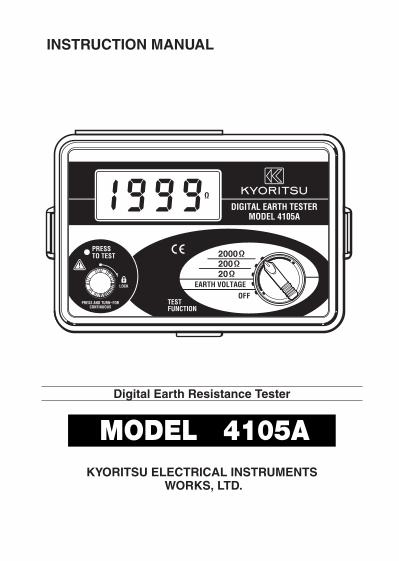
INSTRUCTION MANUAL
Digital Earth Resistance Tester
MODEL 4105AKYORITSU ELECTRICAL INSTRUMENTS
WORKS, LTD.
01-07 92-1494
KYORITSU ELECTRICAL INSTRUMENTSWORKS, LTD.No.5-20,Nakane 2-chome, Meguro-ku, Tokyo 152-0031 JapanPhone :(03) 3723-0131 Fax : (03) 3723-0152URL : http://www.kew-ltd.co.jpE-mail : [email protected] : Uwajima & Ehime
Kyoritsu reserves the rights to change specifications or designs described in
this manual without notice and without obligations.
DISTRIBUTOR
1. Safty Precautions
The instrument is designed, manufactured, tested and shipped in prime
condition in accordance with the following standards.
IEC 61010-1 Overvoltage CAT III 300V Pollution Degree 2IEC 61010-2-31IEC 61557-1,5IEC 60529 (IP54)
This instruction manual contains warnings and safety rules which must beobserved by the user to ensure safety operation of the instrument and toretain it in safe condition. Therefore, read through these instructions beforeusing the instrument.
WARNINGRead through and understand instructions contained in this manual
before using the instrument.Save and keep the manual handy to enable quick reference whenever
necessary.Be sure to use the instrument only in its intended applications and to
follow measurement procedures described in the manual.Be sure to understand and follow all safety instructions contained in the
manual.Be sure to observe the above rules strictly. Not following the instructionsmay cause injury or instrument damage.
The symbol on the instrument means that the user must refer to the
manual for safe operation of the instrument. There are three kinds of thesymbol . Read the instructions following each symbol carefully.
---- 1 ----
CONTENTS
1. Safety Precautions …………………………………………………………… 12. Features ………………………………………………………………………… 43. Specifications…………………………………………………………………… 54. Layout Diagram ………………………………………………………………… 85. Preparation for Measurement ………………………………………………… 9
5-1 Battery Voltage Check …………………………………………………… 95-2 Connecting Test Probes ………………………………………………… 9
6. Operating Instructions ………………………………………………………… 96-1 Principle of Measurement ……………………………………………… 96-2 Precise Measurement …………………………………………………… 106-3 Simplified Measurement ………………………………………………… 11
7. Battery Replacement ………………………………………………………… 148. Notes on Housing Case & Accessories …………………………………… 15
8-1 Case Lid…………………………………………………………………… 158-2 How to Fit Strap Belt …………………………………………………… 15
9. Before Sending for Service ………………………………………………… 1610. Service ……………………………………………………………………… 17
DANGER is reserved for conditions and actions that are likely to cause
serious or fatal injury.WARNING is reserved for conditions and actions that can cause
serious or fatal injury.CAUTION is reserved for conditions and actions that can cause minor
injury or instrument damage.
DANGERMake sure that the range selector switch is set to a desired position
before making measurement.Do not make measurement in the presence of flammable gasses.
Otherwise, the use of the instrument may cause sparkling, which leadsto an explosion.Never attempt to connect the test probe if the instrument or your hand is
wet.Do not apply an electrical quantity exceeding the allowable limit of a
measuring range.Never open the battery compartment cover while making measurement.
WARNINGNever attempt to make measurement, if any abnormal conditions are
noted, such as broken case, cracked test probe and exposed metalparts.Never turn the range selector switch with test probe connected to the
equipment under test.Do not install substitute parts or make any decomposition or
modification to the instrument. Return the instrument to Kyoritsu or yourdistributor for repair or re-calibration.Do not replace batteries when the surface of the instrument is wet.Always set the range switch to the OFF position before opening the
battery compartment cover for battery replacement.
CAUTIONMake sure that the test probe are securely connected to the terminal of
the instrument.Be sure to set the range selector switch to the OFF position after use.
When the instrument will not be in use for a long period of time, place itin storage after removing the batteries.Do not expose the instrument to the direct sun, extreme temperature
and humidity or dew fall.Use a damp cloth soaked in water or neutral detergent for cleaning the
instrument. Do not use abrasives or solvents.When the instrument is wet, make sure to let it dry before putting it in
storage.
---- 3 -------- 2 ----

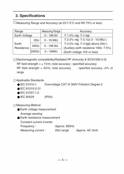
3. Specifications
Measuring Range and Accuracy (at 23 5°C and RH 75% or less)
Range Measuring Range AccuracyEarth Voltage 0 - 199.9V 1.0% rdg 4 dgt
20Ω 0 - 19.99Ω 2.0% rdg 0.1Ω( 0 - 19.99Ω )Earth 2.0% rdg 3 dgt( above 20Ω )Resistance
200Ω 0 - 199.9Ω(Auxiliary earth resistance 100Ω 5%)
2000Ω 0 - 1999Ω (Earth voltage 10V or less)
Electromagnetic compatibility(Radiated RF immunity & IEC61000-4-3)
RF field strength = ≤ 1V/m, total accuracy : specified accuracyRF field strength = 3V/m, total accuracy : specified accuracy +5% ofrange
Applicable StandardsIEC 61010-1 Overvoltage CAT III 300V Pollution Degree 2IEC 61010-2-31IEC 61557-1,5IEC 60529 (IP54)
Measuring MethodEarth voltage measurement
Average sensingEarth resistance measurement
Constant current inverterFrequency : Approx. 820HzMeasuring current : 20Ω range Approx. AC 3mA
---- 5 ----
2. Features
MODEL 4105A is an earth resistance tester for testing power distributionlines, in-house wiring system, electrical appliances etc. It also has an earthvoltage range for earth voltage measurement.
Designed to safety standard IEC 61557.
Dust and drip proof construction in conformity with IEC 60529 (IP54).
Measurement can be made even under adverse weather conditions.
Large, easy-to-read LCD digital display.
Simplified measurement probe has a structure that both the alligator clip
and the test bar are available.
Warns when earth resistance of auxiliary earth spikes exceeds the
permissible limit.
Convenient carrying soft bag for accessories etc.
---- 4 ----
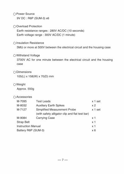
Power Source
9V DC : R6P (SUM-3) x6
Overload Protection
Earth resistance ranges : 280V AC/DC (10 seconds)Earth voltage range : 300V AC/DC (1 minute)
Insulation Resistance
5MΩ or more at 500V between the electrical circuit and the housing case
Withstand Voltage
3700V AC for one minute between the electrical circuit and the housingcase
Dimensions
105(L) x 158(W) x 70(D) mm
Weight
Approx. 550g
Accessories
M-7095 Test Leads x 1 setM-8032 Auxiliary Earth Spikes x 2 M-7127 Simplified Measurement Probe x 1 set
(with safety alligator clip and flat test bar)M-9084 Carrying Case x 1 Strap Belt x 1 Instruction Manual x 1Battery R6P (SUM-3) x 6
---- 7 ----
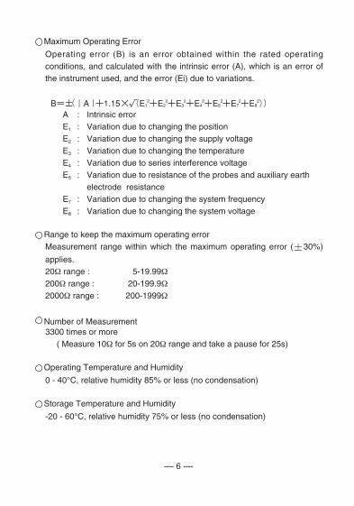
Maximum Operating Error
Operating error (B) is an error obtained within the rated operatingconditions, and calculated with the intrinsic error (A), which is an error ofthe instrument used, and the error (Ei) due to variations.
A : Intrinsic errorE1 : Variation due to changing the positionE2 : Variation due to changing the supply voltageE3 : Variation due to changing the temperatureE4 : Variation due to series interference voltageE5 : Variation due to resistance of the probes and auxiliary earth
electrode resistanceE7 : Variation due to changing the system frequencyE8 : Variation due to changing the system voltage
Range to keep the maximum operating errorMeasurement range within which the maximum operating error ( 30%)
applies.20Ω range : 5-19.99Ω200Ω range : 20-199.9Ω2000Ω range : 200-1999Ω
Number of Measurement3300 times or more
( Measure 10Ω for 5s on 20Ω range and take a pause for 25s)
Operating Temperature and Humidity
0 - 40°C, relative humidity 85% or less (no condensation)
Storage Temperature and Humidity
-20 - 60°C, relative humidity 75% or less (no condensation)
---- 6 ----
Power Source
9V DC : R6P (SUM-3) x6
Overload Protection
Earth resistance ranges : 280V AC/DC (10 seconds)Earth voltage range : 300V AC/DC (1 minute)
Insulation Resistance
5MΩ or more at 500V between the electrical circuit and the housing case
Withstand Voltage
3700V AC for one minute between the electrical circuit and the housingcase
Dimensions
105(L) x 158(W) x 70(D) mm
Weight
Approx. 550g
Accessories
M-7095 Test Leads x 1 setM-8032 Auxiliary Earth Spikes x 2 M-7127 Simplified Measurement Probe x 1 set
(with safety alligator clip and flat test bar)M-9084 Carrying Case x 1 Strap Belt x 1 Instruction Manual x 1Battery R6P (SUM-3) x 6
---- 7 ----
Maximum Operating Error
Operating error (B) is an error obtained within the rated operatingconditions, and calculated with the intrinsic error (A), which is an error ofthe instrument used, and the error (Ei) due to variations.
A : Intrinsic errorE1 : Variation due to changing the positionE2 : Variation due to changing the supply voltageE3 : Variation due to changing the temperatureE4 : Variation due to series interference voltageE5 : Variation due to resistance of the probes and auxiliary earth
electrode resistanceE7 : Variation due to changing the system frequencyE8 : Variation due to changing the system voltage
Range to keep the maximum operating errorMeasurement range within which the maximum operating error ( 30%)
applies.20Ω range : 5-19.99Ω200Ω range : 20-199.9Ω2000Ω range : 200-1999Ω
Number of Measurement3300 times or more
( Measure 10Ω for 5s on 20Ω range and take a pause for 25s)
Operating Temperature and Humidity
0 - 40°C, relative humidity 85% or less (no condensation)
Storage Temperature and Humidity
-20 - 60°C, relative humidity 75% or less (no condensation)
---- 6 ----
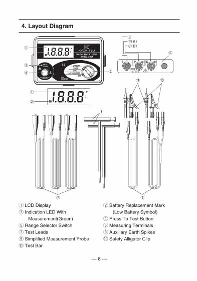
4. Layout Diagram
q LCD Display w Battery Replacement Marke Indication LED With qq(Low Battery Symbol)qqMeasurement(Green) r Press To Test Buttont Range Selector Switch y Measuring Terminalsu Test Leads i Auxiliary Earth Spikeso Simplified Measurement Probe !0 Safety Alligator Clip!1 Test Bar
---- 8 ----
5. Preparation for Measurement
5-1 Battery Voltage CheckTurn on the instrument. If the display is clear without low battery symbol" " showing, battery voltage is sufficient. If the display blanks or " " isindicated, replace the batteries according to section 7 for BatteryReplacement.
5-2 Connecting Test ProbeInsert the plug of the probe securely into the terminals of the instrument.Loose connection may result in inaccurate measurements.
6.Operating Instructions
DANGERThe instrument will produce a maximum voltage of about 50V between
terminals E-C in earth resistance function. Take enough caution toavoid electric shock hazard.When measuring earth voltage, do not apply voltage greater than 200V
between measuring terminals.When measuring earth resistance, do not apply voltage between
measuring terminals.
6-1 Principle of MeasurementThis instrument makes earth resistance measurement with fall-of-potential method, which is a method to obtain earth resistance value Rxby applying AC constant currentI between the measurementobject E (earth electrode) and C(current electrode), and findingout the potential difference Vbetween E and P (potentialelectrode).
Rx = V / I
---- 9 ----
---- 10 ----
20Ω when the earth resistance is low. This indicated value is the earthresistance of the earthed equipment under test.
Note : If the auxiliary earth resistance of auxiliary earth spike C is too
high to make measurement, the display reads ' . . . '. Recheck theconnection of test leads and the earth resistance of auxiliary earthspike.
CAUTIONIf measurement is made with the probes twisted or in touch with each
other, the reading of the instrument may be affected by induction. Whenconnecting the probes, make sure that they are separated.If earth resistance of auxiliary earth spikes is too large, it may result in
inaccurate measurement. Make sure to stick the auxiliary earth spike Pand C into the moist part of the earth carefully, and ensure sufficientconnections between the respective connections.
6-3 Simplified Measurement (with Test Probe M-7127)Use this method when the auxiliary earth spike cannot be stuck. In thismethod, an existing earth electrode with a low earth resistance, such asa metal water pipe, a common earth of a commercial power supply andan earth terminal of a building, can be used with two-terminal method(E,P).Use the simplified measurement probe attached which has a convenientstructure that both the safety alligator clip and the test bar are available.
q Wiring
Make connection as shown in the figure.
---- 11 ----
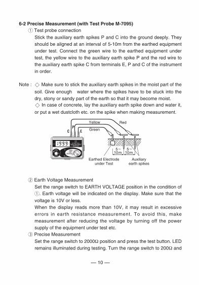
6-2 Precise Measurement (with Test Probe M-7095)q Test probe connection
Stick the auxiliary earth spikes P and C into the ground deeply. Theyshould be aligned at an interval of 5-10m from the earthed equipmentunder test. Connect the green wire to the earthed equipment undertest, the yellow wire to the auxiliary earth spike P and the red wire tothe auxiliary earth spike C from terminals E, P and C of the instrumentin order.
Note : Make sure to stick the auxiliary earth spikes in the moist part of the
soil. Give enough water where the spikes have to be stuck into thedry, stony or sandy part of the earth so that it may become moist.
In case of concrete, lay the auxiliary earth spike down and water it,
or put a wet dustcloth etc. on the spike when making measurement.
w Earth Voltage Measurement
Set the range switch to EARTH VOLTAGE position in the condition ofq. Earth voltage will be indicated on the display. Make sure that the
voltage is 10V or less.When the display reads more than 10V, it may result in excessiveerrors in earth resistance measurement. To avoid this, makemeasurement after reducing the voltage by turning off the powersupply of the equipment under test etc.
e Precise Measurement
Set the range switch to 2000Ω position and press the test button. LEDremains illuminated during testing. Turn the range switch to 200Ω and

---- 10 ----
20Ω when the earth resistance is low. This indicated value is the earthresistance of the earthed equipment under test.
Note : If the auxiliary earth resistance of auxiliary earth spike C is too
high to make measurement, the display reads ' . . . '. Recheck theconnection of test leads and the earth resistance of auxiliary earthspike.
CAUTIONIf measurement is made with the probes twisted or in touch with each
other, the reading of the instrument may be affected by induction. Whenconnecting the probes, make sure that they are separated.If earth resistance of auxiliary earth spikes is too large, it may result in
inaccurate measurement. Make sure to stick the auxiliary earth spike Pand C into the moist part of the earth carefully, and ensure sufficientconnections between the respective connections.
6-3 Simplified Measurement (with Test Probe M-7127)Use this method when the auxiliary earth spike cannot be stuck. In thismethod, an existing earth electrode with a low earth resistance, such asa metal water pipe, a common earth of a commercial power supply andan earth terminal of a building, can be used with two-terminal method(E,P).Use the simplified measurement probe attached which has a convenientstructure that both the safety alligator clip and the test bar are available.
q Wiring
Make connection as shown in the figure.
---- 11 ----
6-2 Precise Measurement (with Test Probe M-7095)q Test probe connection
Stick the auxiliary earth spikes P and C into the ground deeply. Theyshould be aligned at an interval of 5-10m from the earthed equipmentunder test. Connect the green wire to the earthed equipment undertest, the yellow wire to the auxiliary earth spike P and the red wire tothe auxiliary earth spike C from terminals E, P and C of the instrumentin order.
Note : Make sure to stick the auxiliary earth spikes in the moist part of the
soil. Give enough water where the spikes have to be stuck into thedry, stony or sandy part of the earth so that it may become moist.
In case of concrete, lay the auxiliary earth spike down and water it,
or put a wet dustcloth etc. on the spike when making measurement.
w Earth Voltage Measurement
Set the range switch to EARTH VOLTAGE position in the condition ofq. Earth voltage will be indicated on the display. Make sure that the
voltage is 10V or less.When the display reads more than 10V, it may result in excessiveerrors in earth resistance measurement. To avoid this, makemeasurement after reducing the voltage by turning off the powersupply of the equipment under test etc.
e Precise Measurement
Set the range switch to 2000Ω position and press the test button. LEDremains illuminated during testing. Turn the range switch to 200Ω and
w Earth Voltage Measurement
Set the range switch to EARTH VOLTAGE position in the condition ofq. Earth voltage will be indicated on the display. Make sure that the
voltage is 10V or less.When the display reads more than 10V, it may result in excessiveerrors in earth resistance measurement. To avoid this, makemeasurement after reducing the voltage by turning off the powersupply of the equipment under test etc.
e Simplified Measurement
Set the range switch to 2000Ω position and press the test button. LEDremains illuminated during testing. Turn the range switch to 200Ω and20Ω when the earth resistance is low. This indicated value is the earthresistance of the earthed equipment under test.
Note : If the auxiliary earth resistance of auxiliary earth spike C is too
high to make measurement, the display reads ' . . . '. Recheck theconnection of each test lead and the earth resistance of auxiliaryearth spike.
r Simplified Measurement Value
Two-terminal method is used for simplified measurement. In thismethod, earth resistance value re of earth electrode connected toterminal P is added to true earth resistance value Rx and shown asan indicated value Re.
Re = Rx + reIf the re is known beforehand, true earth resistance value Rx iscalculated as follows.
Rx = Re --- re
---- 13 ----
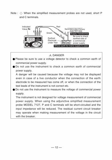
Note : When the simplified measurement probes are not used, short P
and C terminals.
DANGERPlease be sure to use a voltage detector to check a common earth of
commercial power supply.Do not use the instrument to check a common earth of commercial
power supply.A danger will be caused because the voltage may not be displayedeven in case of a live conductor when the connection of the earthelectrode to be measured has come off, or when the connection of thetest leads of the instrument is not correct etc.Do not use the instrument to measure the voltage of commercial power
supply.The instrument is not designed for voltage measurement of commercialpower supply. When using the adjunctive simplified measurementprobe MODEL 7127, P and C terminals will be short-circuited and the
input impedance will be reduced. The residual current circuit breakermay operate when making measurement of the voltage in the circuitwith the breaker.
---- 12 ----
w Earth Voltage Measurement
Set the range switch to EARTH VOLTAGE position in the condition ofq. Earth voltage will be indicated on the display. Make sure that the
voltage is 10V or less.When the display reads more than 10V, it may result in excessiveerrors in earth resistance measurement. To avoid this, makemeasurement after reducing the voltage by turning off the powersupply of the equipment under test etc.
e Simplified Measurement
Set the range switch to 2000Ω position and press the test button. LEDremains illuminated during testing. Turn the range switch to 200Ω and20Ω when the earth resistance is low. This indicated value is the earthresistance of the earthed equipment under test.
Note : If the auxiliary earth resistance of auxiliary earth spike C is too
high to make measurement, the display reads ' . . . '. Recheck theconnection of each test lead and the earth resistance of auxiliaryearth spike.
r Simplified Measurement Value
Two-terminal method is used for simplified measurement. In thismethod, earth resistance value re of earth electrode connected toterminal P is added to true earth resistance value Rx and shown asan indicated value Re.
Re = Rx + reIf the re is known beforehand, true earth resistance value Rx iscalculated as follows.
Rx = Re --- re
---- 13 ----
Note : When the simplified measurement probes are not used, short P
and C terminals.
DANGERPlease be sure to use a voltage detector to check a common earth of
commercial power supply.Do not use the instrument to check a common earth of commercial
power supply.A danger will be caused because the voltage may not be displayedeven in case of a live conductor when the connection of the earthelectrode to be measured has come off, or when the connection of thetest leads of the instrument is not correct etc.Do not use the instrument to measure the voltage of commercial power
supply.The instrument is not designed for voltage measurement of commercialpower supply. When using the adjunctive simplified measurementprobe MODEL 7127, P and C terminals will be short-circuited and the
input impedance will be reduced. The residual current circuit breakermay operate when making measurement of the voltage in the circuitwith the breaker.
---- 12 ----
---- 15 ----
7. Battery Replacement
DANGERNever attempt to open the battery compartment cover, if the outer
surface of the instrument is wet.Never attempt to replace batteries while making measurement. To avoid
shock hazard, turn the instrument off and disconnect the test leads andthe probes from the instrument before opening the battery compartmentcover.
CAUTIONDo not mix new and old batteries.Install batteries in the orientation as shown inside the battery
compartment, observing correct polarity.
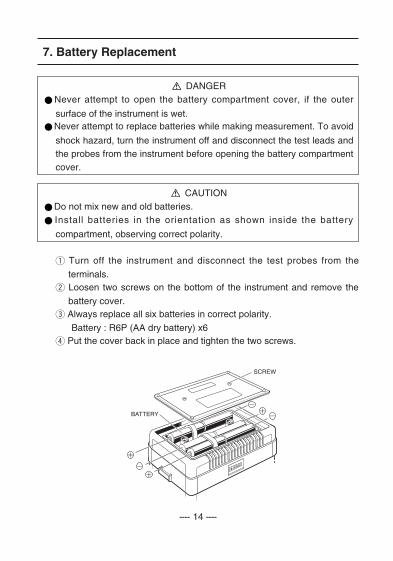
q Turn off the instrument and disconnect the test probes from the
terminals.w Loosen two screws on the bottom of the instrument and remove the
battery cover.e Always replace all six batteries in correct polarity.
Battery : R6P (AA dry battery) x6r Put the cover back in place and tighten the two screws.
---- 14 ----
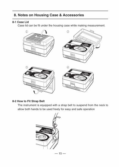
8. Notes on Housing Case & Accessories
8-1 Case LidCase lid can be fit under the housing case while making measurement.
8-2 How to Fit Strap BeltThe instrument is equipped with a strap belt to suspend from the neck toallow both hands to be used freely for easy and safe operation
---- 15 ----
7. Battery Replacement
DANGERNever attempt to open the battery compartment cover, if the outer
surface of the instrument is wet.Never attempt to replace batteries while making measurement. To avoid
shock hazard, turn the instrument off and disconnect the test leads andthe probes from the instrument before opening the battery compartmentcover.
CAUTIONDo not mix new and old batteries.Install batteries in the orientation as shown inside the battery
compartment, observing correct polarity.
q Turn off the instrument and disconnect the test probes from the
terminals.w Loosen two screws on the bottom of the instrument and remove the
battery cover.e Always replace all six batteries in correct polarity.
Battery : R6P (AA dry battery) x6r Put the cover back in place and tighten the two screws.
---- 14 ----
8. Notes on Housing Case & Accessories
8-1 Case LidCase lid can be fit under the housing case while making measurement.
8-2 How to Fit Strap BeltThe instrument is equipped with a strap belt to suspend from the neck toallow both hands to be used freely for easy and safe operation
---- 17 ----
9. Before Sending for Service
If this instrument should fail to operate correctly, return it to your nearestdistributor stating the exact nature of the fault. Before returning theinstrument follow the trouble-shooting guide shown below.
If the instrument does not turn on;
Check whether batteries are missing or they are installed incorrectpolarity. Note that batteries were not installed in the instrument at the timeof shipment.
If the display reads '1 . . . ' in earth voltage measurement;
A voltage exceeding 200V is being applied to the instrument.Halt the measurement immediately, otherwise the instrument may bedamaged.
If the display reads ' . . . ' in normal earth resistance measurement;
Stick the auxiliary earth spikes deeper into the earth, or stick them at otherlocations; orAdd moisture to the part of the earth where C auxiliary earth spike is stuck( connected with the red wire ); andShort the three test leads and check if the display indicates a value near ' 0.00 '. (See section 6 for details.)
If the display reads ' . . . ' in simplified earth resistance measurement;
Check if the connection to a metal water pipe, a common earth ofcommercial power supply, etc., is secure; orUse another metal water pipe, common earth of commercial powersupply, etc.
---- 16 ----
10. Service
If this instrument should fail to operate correctly, return to your nearestdistributors stating the exact nature of the fault.