model 61 ob - stanford university
TRANSCRIPT

OPERATOR'S MANUAL
MODEL 61 OB
COR-A.TROL
H IGH VOLTAG E SUPPLY/AMPLIFI ER/CONTROLLER
Paragraph
TABLE OF CONTENTS
Title Paqe
11 . 11 . 21 . 31 . 3 . 11 . 3 . 21 . 4
22 . 12 . 1 . 12 . 1 . 1 . 12 . 1 . 1 . 22 . 1 . 1 . 2 . 12 . 1 . 1 . 2 . 22 . 1 . 1 . 2 . 32 . 1 . 1 . 32 . 1 . 1 . 3 . 12 . 1 . 1 . 3 . 22 . 1 . 1 . 42 . 1 . 1 . 4 . 12 . 1 . 1 . 4 . 22 . 1 . 1 . 4 . 32 . 1 . 1 . 4 . 42 . 1 . 1 . 4 . 5
I INSTALLATION
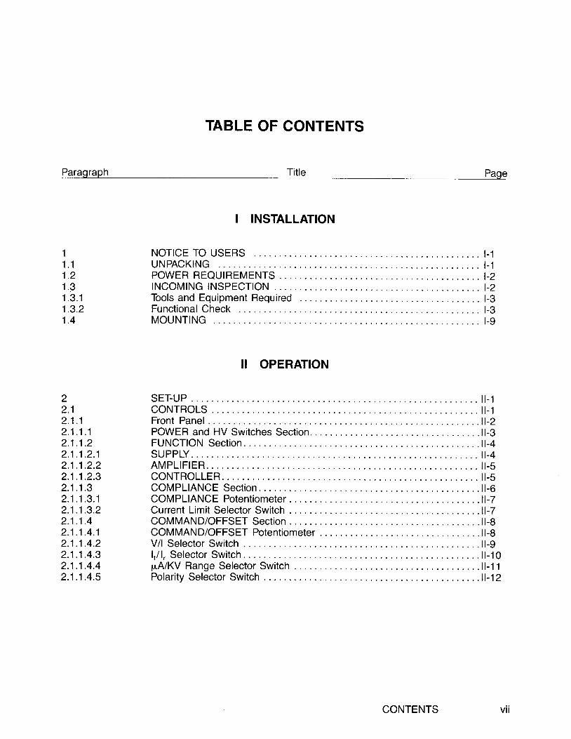
NOTICE TO USERS . . . I -1U N P A C K I N G . . . . I . 1P O W E R R E Q U I R E M E N T S . . . . I - 2T N C O M I N G T N S P E C T | O N . . . . . . . . . . . t - 2Too ls and Equ ipment Requ i red . . . . . . l -3Funct iona l Check . . . . . . l -3M O U N T T N G . . . . . t - 9
II OPERATION
SET-UP . . . i l - 1C o N T R O L S . . . . . . . . . , . i l - 1F r o n t P a n e l . . . . . . . . . . . . 1 1 - 2POWER and HV Switches Section. . . . l l -3F U N C T I O N S e c t i o n . . . . . 1 1 - 4SUPPLY . , . 11 -4A M P L I F I E R . . . . . . i l - sC O N T R O L L E R . . . . . . . . . i l - sC O M P L I A N C E S e c t i o n . . . . . . . . 1 1 - 6C O M P L I A N C E P o t e n t i o m e t e r . . , . . . . . 1 1 - 7C u r r e n t L i m i t S e l e c t o r S w i t c h . . . . . . . . ' 1 - 7C O M M A N D / O F F S E T S e c t i o n . . . . . . . . 1 1 - 8COMMAND/OFFSET Po ten t i ome te r . . . . . . . . l l - 8V / l Se lec to r Sw i t ch . . . . . 11 -9l , / 1 , . Se lec to r Sw i t ch . . . . . l l - 10p A / K V R a n g e S e l e c t o r S w i t c h . . . . . . . 1 1 - 1 1Po la r i t y Se lec to r Sw i t ch . . . . . . . 11 -12
CONTENTS vt l
P-eGgIeph
TABLE OF CONTENTS (Con't)
Title Ecg.-'
ll OPERATIONS (Con't)
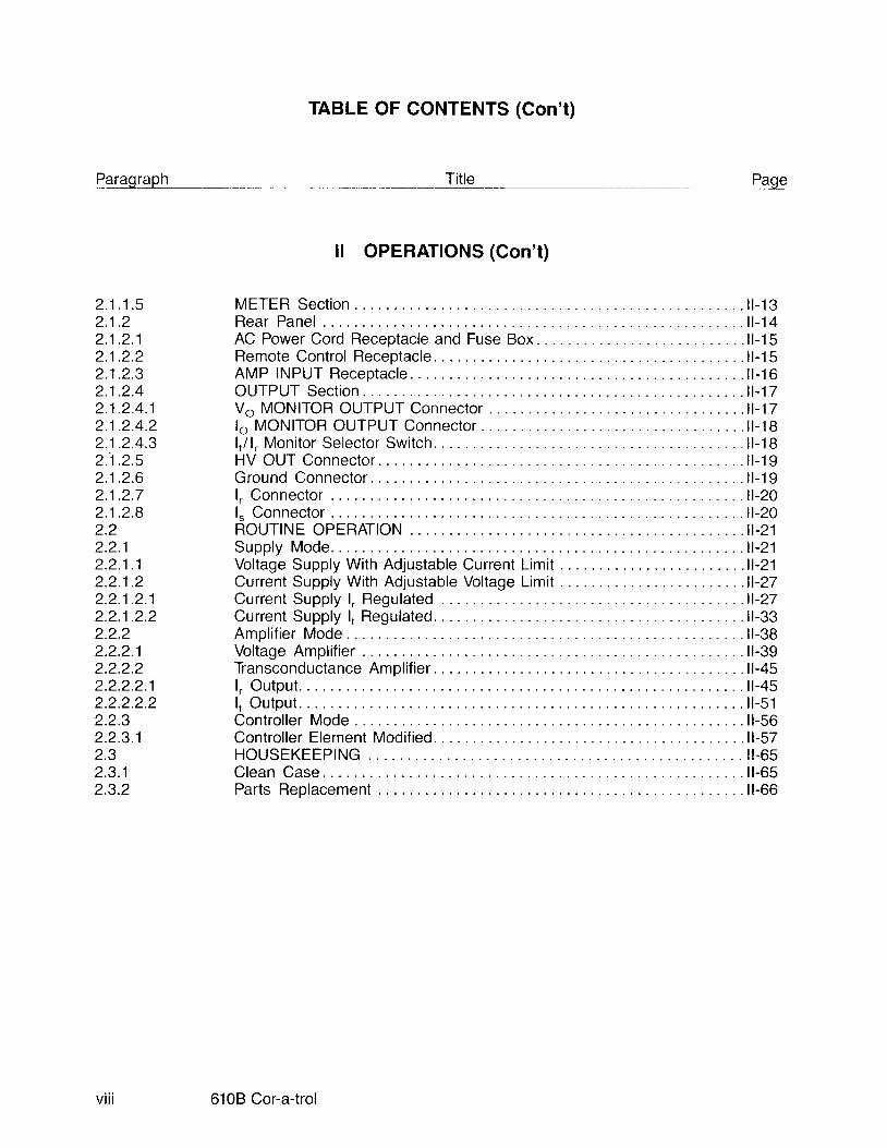
METER Sec t i on . . l l - 13R e a r P a n e l . . . . . . l l - 1 4A C P o w e r C o r d R e c e p t a c l e a n d F u s e B o x . . . . . . . . . 1 1 - 1 5Remote Contro l Receptac le . . . . l l -15A M P I N P U T R e c e p t a c l e . . . . l l - 1 6O U T P U T S e c t i o n . . . . . . . 1 1 - 1 7Vo MONITOR OUTPUT Connector . . .11-17lo MONITOR OUTPUT Connec to r . . . . 11 -18l , /1 , . Moni tor Selector Swi tch. . . l l -18HV OUT Connector . . l l -19Ground Connector . l l -19l , C o n n e c t o r . . . . . . . . . . 1 1 - 2 0l " C o n n e c t o r . . . . . l l - 2 0R O U T I N E O P E R A T T O N . . . . . . . n - 2 1Supp ly Mode . . . . . 11 -21Vol tage Supply Wi th Adjustable Current L imi t . . . . . .11-21Current Supply Wi th Adjustable Vol tage L imi t . . . . . .11-27C u r r e n t S u p p l y l , . R e g u l a t e d . . . . . . . . . 1 1 - 2 7C u r r e n t S u p p l y l , R e g u l a t e d . . . . . . . l l - 3 3Ampl i f ier Mode . l l -38V o l t a g e A m p l i f i e r . . . . . 1 1 - 3 9Tiansconductance Ampl i f ier . . .11-45l . Output . . . l l -45I , Ou tpu t . . . l l - 51Control ler Mode . . l l -56Con t ro l l e r E lemen t Mod i f i ed . . . . 11 -57H O U S E K E E P I N G . . . . . . I I - 6 5C l e a n C a s e . . . . . . 1 1 - 6 5P a r t s R e p l a c e m e n t . . l l - 6 6
2 . 1 . 1 . 52 . 1 . 22 . 1 . 2 . 12 . 1 . 2 . 22 . 1 . 2 . 32 . 1 . 2 . 42 . 1 . 2 . 4 . 12 . 1 . 2 . 4 . 22 . 1 . 2 . 4 . 32 . 1 . 2 . 52 . 1 . 2 . 62 . 1 . 2 . 72 . 1 . 2 . 82.22 .2 .12 . 2 . 1 . 12 . 2 . 1 . 22 . 2 . 1 . 2 . 12 . 2 . 1 . 2 . 22.2.22 .2 .2 .12 .2 .2 .22 .2 .2 .2 .12 .2 .2 .2 .22 .2 .32 .2 .3 .12 .32 .3 .12.3.2
v i i i 6108 Cor-a-trol
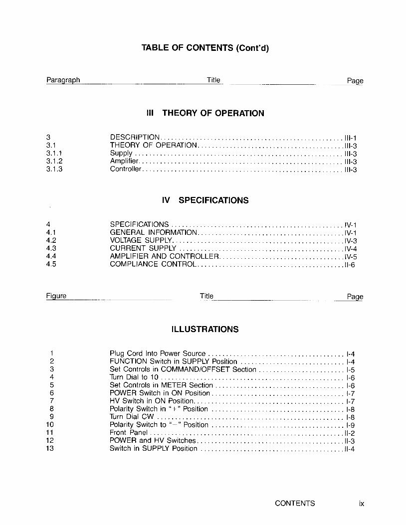
TABLE OF CONTENTS (Cont'd)
Paragraph Title Paqe
33 . 13 . 1 . 13 . 1 . 23 . 1 . 3
44 . 14 .24.34.44.5
Figure
II I THEORY OF OPERATION
D E S C R | P T | O N . . . . . . . . . i l t - 1T H E O R Y O F O P E R A T I O N . . . . . I I I - 3S u p p l y . . . . l t t - 3Amp l i f i e r . . . t t t - 3Contro l ler . . l l l -3
IV SPECIFICATIONS
S P E C I F I C A T I O N S . . . . . . I V - 1G E N E R A L I N F O R M A T I O N . . . . . I V - 1VOLTAGE SUPPLY. . . . IV-3C U R R E N T S U P P L Y . . . . I V - 4AMPLIF IER AND CONTROLLER. . . . . IV -sc o M P L t A N C E C O N T R O L . . . . . . . . . . i l - 6
Tit le Paqe
123456789
1 01 11 21 3
ILLUSTRATIONS
P l u g C o r d l n t o P o w e r S o u r c e . . . . . . . . 1 - 4FUNCTION Swi tch in SUPPLY Posi t ion . . . . .1-4Set Contro ls in COMMAND/OFFSET Sect ion . . . . . . l -5T u r n D i a l t o 1 0 . . . . . . . l - 6Set Contro ls in METER Sect ion . . . . . t -6P O W E R S w i t c h i n O N P o s i t i o n . . . . . . . l - ZH V S w i t c h i n O N P o s i t i o n . . . . . . l - 7P o l a r i t y S w i t c h i n " + " P o s i t i o n . . . . . . . l - 8T u r n D i a l C W . . . . . . . . . l - BPolar i ty Swi tch to " - " Posi t ion . . . . . l -gF r o n t P a n e l . . . . . . . . . . . . 1 i r - 2P O W E R a n d H V S w i t c h e s . . . . . 1 t - 3Swi tch in SUPPLY Posi t ion . . . . l l -4
IXCONTENTS

frgqre
1 41 51 61 71 B1 9202 12223242526z l2829303 13233343536373B394041424344454647484950515253
TABLE OF CONTENTS (Cont'd)
Tit le ___ Page
I LLUSTRATIONS (Cont'd)
S w i t c h i n A M P L I F I E R P o s i t i o n . . . . . . . l l - 5Swi tch in CONTROLLER Posi t ion . . . l l -6Amber LED. . . l l - 6C O M P L I A N C E P o t e n t i o m e t e r . . . . . . . . l l - 7C u r r e n t L i m i t S e l e c t o r S w i t c h . . . . . . . . l l - 7COMMAND/OFFSET Po ten t i ome te r . . . . . . . 11 -9V/l Selector Switch . l l-9l , / l , , S e l e c t o r S w i t c h . . . . 1 1 - 1 0p A / K V R a n g e S e l e c t o r S w i t c h . . . . . . . l l - 1 2Po la r i t y Se lec to r Sw i t ch . . . . . 11 -13METER Sect ion Contro ls . . l l -13R e a r P a n e l C o n t r o l s . . . . 1 1 - 1 4AC Power Cord Recep tac le and Fuse Box . . . . . . . 11 -15Remote Contro l Receptac le . . . . l l -15A M P I N P U T R e c e p t a c l e . . . . . . . l l - 1 6P in Connec t i ons . . . l l - 16Vo MONITOR OUTPUT Connector . . . .11-17lo MONITOR OUTPUT Connec to r . . . . 11 -18l,/1,, Monitor Selector Switch . . . l l -18H V O U T C o n n e c t o r . . . . . 1 1 - 1 9G r o u n d C o n n e c t o r . . . . . 1 1 - 1 9l , C o n n e c t o r . . . . . . . . 1 1 - 2 0l = C o n n e c t o r . . . . . . l l - 2 0POWER and HV Switches Set to OFF. . . . . . l l -21E x a m p l e o f R e a r P a n e l C o n n e c t i o n s . . . . . . . . l l - 2 2Plug Power Cord In to 6108 Receptac le . . . . . l l -23Plug Power Cord Into Power Source l l-23Examp le o f F ron t Pane l Se t t i ngs . . . . . l l - 24POWER Swi tch to ON . . l l -25HV Switch to ON l l-25POWER and HV Sw i t ches to OFF. . . . l l - 27S a m p l e R e a r P a n e l H o o k - u p l , R e g u l a t e d . . . . . . . . l l - 2 8Plug Power Cord Into 6108 Receptacle . . . . l l -29Plug Power Cord Into Power Source . . l l -29Example of Front Panel Sett ings . . . . .11-30POWER Swirch to ON .. l l -32H V S w i t c h t o O N . . . . . . . 1 1 - 3 2POWER and HV Switches to OFF. . . . l l -33S a m p l e R e a r P a n e l H o o k - u p l , R t , g u l a t e d . . . . . . . . . 1 1 - 3 4Plug Power Cord In to 6108 Receptac le . . . . . l l -35
6108 Cor-a-trol
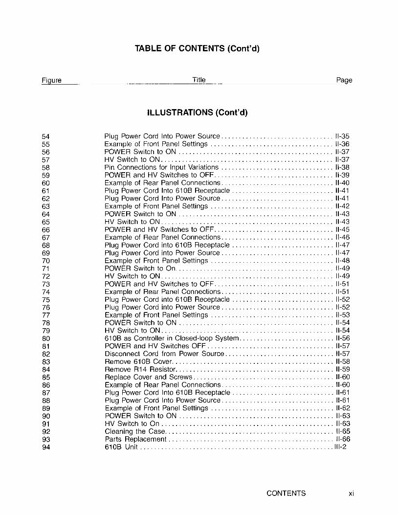
TABLE OF CONTENTS (Cont'd)
Fioure Title Paqe
54555b5758596061626364656667686970717273747576777879808182838485868788B9909 1929394
I L1-USTRAfIONS (Cont'd)
Plug Power Cord Into Power Source . . l l -35Example of Front Panel Sett ings . . l l -36POWER Swi t ch to ON . . l l - 37HV Sw i t ch to ON . l l - 37Pin Connections for Input Variat ions .. l l -38POWER and HV Switches to OFF. . . l l -39Examo le o f Rear Pane l Connec t i ons . . . . . . . . l l - 40P lug Power Cord In to 6108 Recep tac le . . . . . l l - 41Plug Power Cord Into Power Source . . l l -41Example of Front Panel Set t ings . . . . . l l -42POWER Swi tch to ON . . l l -43HV Switch to ON . l l -43POWEB and HV Swi tches to OFF. . . . l l -45Example of Rear Panel Connect ions. . . . . . l l -46P lug Power Cord i n to 6108 Recep tac le . . . . . l l - 47Plug Power Cord into Power Source . . ll-47Example of Front Panel Set t ings . . . . . l l -48POWER Swi tch to On. . . l l -49HV Switch to ON . l l -49POWER and HV Swi tches to OFF. . . . l l -51E x a m p l e o f R e a r P a n e l C o n n e c t i o n s . . . . . . . . l l - 5 1Plug Power Cord in to 6108 Receptac le . . . . . l l -52Plug Power Cord into Power Source .. l l -52Example of Front Panel Set t ings . . . . . l l -53POWER Switch to ON .. l l -54HV Switch to ON . l l -546108 as Contro l ler in Closed- loop System . . . l l -56P O W E R a n d H V S w i t c h e s O F F . . . . . . l l - 5 7Disconnect Cord from Power Source . ll-57R e m o v e 6 1 0 8 C o v e r . . . . . . . l l - 5 8Remove R14 Res is to r . . . . . . . . . l l - 59R e p l a c e C o v e r a n d S c r e w s . . . . . . . . . . l l - 6 0Examp le o f Rear Pane l Connec t i ons . . . . . . . . l l - 60P lug Power Cord In to 6108 Recep tac le . . . . . l l - 61Plug Power Cord lnto Power Source . . l l -61Example of Front Panel Set t ings . . . . . l l -62POWER Switch to ON .. l l -63HV Switch to On . l l -63C lean ing the Case . . . . . . l l - 65Par t s Rep lacemen t . . . . . l l - 666 1 0 8 U n i t . . . . . . . 1 1 1 - 2
xiCONTENTS

TABLE OF CONTENTS (Cont'd)
Letter -!cg.
APPENDICES
A G l o s s a r v o f T e r m s . . . . . . A - 1
Title
xii 6108 Cor-a-trol
1 .1
SECTION 1 INSTALLATION
NOTICE TO USERS
Warnings and Cautions are interspersed with instructions in this rnanual to make you aware of thehdzards you may encounter. Warnings are used to advise you of an action or actions which may causeharm to you, the operator. Cautions are used to advise you of an action or actions which may causeharm to the equipment.
UNPACKING
Upon receipt of the package from the shippel visually inspect the shipping container for any dents orother damage. Note any such irregularit ies and have the shipper verify the damage. Report thedamage to the appropriate insurance authority immediately.
l f no externaldamage has been found, then remove the instrument from the packing. Visually inspectthe casing for physical damage, i .e., dents, nicks, scratches, broken f i t t ings, loose wires, etc. In theevent of damage, notify the factory or your nearest Trek representative. Attempts to use a damagedinstrument may cause permanent damage to the unit.
Section I Installation l - 1
1.2 POWER REQUIREMENTS
The 6108 is equipped with a standard 3-prong plug providing a grounded chassis when the cord isused in a grounded power receptacle.
WARNING
Make no attempt to bypass the ground prongin the power cable. This is a safety feature andany attempt to negate i t can result in a painfulshock to the user and/or damage to theequipment .
Ensure that the power supply available in your area corresponds to the voltage requirements indicatedon the label at the back of the 6108. The 6108 operates from a standard 110 VAC, 50 to 60 Hz powersupply without alterations.
INCOMING INSPECTION
The 610B undergoes extensive checks and adjustments at the factory and should require no init ialcal ibration. As part of the incoming irrspection on equipment you may wish to perform a funcitonalcheck.
1 .3
l - 2 6108 Cor-a-trol

1.3.1 Tools and Equipment Required
No special tools or equipment are required to perform the functional check on the 610B.
1.3.2 Functional Check
Prior to start ing the functional check, read the descript ion on the 6108 controls. This proceduredesigned to verify only the basic operation of the instrument. To perform the functional check:
WARNINGTh is equ ipmen t genera tes h igh vo l tages .Read al l instructions and warnings before pro-ceeding. Use caut ion when operat ing theequipment .
CAUTIONMake no attempt to bypass the ground featurein the power cable. This is a safety feature andany attempt to negate it can result in a painfulshock to the user and/or damage to theequipment .
Section I lnstallation t - 3

Plug the 6108 power cord into a standard power source (see Figure 1). Do not plug in the high-voltage cable.
Figure 1. Plug Cord into Power Source
b. Set the FUNCTION switch to SUPPLY (see Figure 2).
FUNCTIONSWITCH
,a=\i r/r-\\\\I t \ ) l t t\ v/i
co)
D t 0o o@ ( o
Figure 2. FUNCTION Switch in SUPPLY Position
t - 4
@oar i)\_:J
@o@
SUP P LY
A M P L I F I E R
CONTROLLE R
6'10B Cor-a-trol

c. In the COMMAND/OFFSET Section:
(1) Set the selector switch to the "V" position (see Figure 3).
(2) Set the range selector switch to the "0-10 KV" position (refer to Figure 3).
(3) Adjust the potentiometer dial to zeroby turning the dial fully counterclockwise (CCW). You mayneed to unlock the dial by pushing up on the lever at the base of the dial (refer to Figure 3).
(4) Flip the polarity switch to the OFF position (refer to Figure 3).
Figure 3. Set Controls in COMMAND/OFFSET Section
AI
o o@ ( @
Section I Instal lat ion t - 5
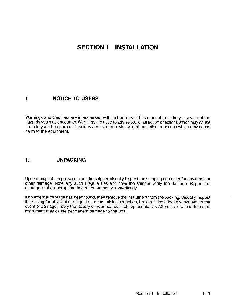
A Adjust the COMPLIANCE LEVEL potentiometer dial to "10" by turning the dial ful ly clockwise(CW) You may need to unlock the control by pushing up on the lever at the base of the dial to makethis adjustment. Reset the lock when the dial is set (see Figure 4).
Figure 4. Turn Dial to 10
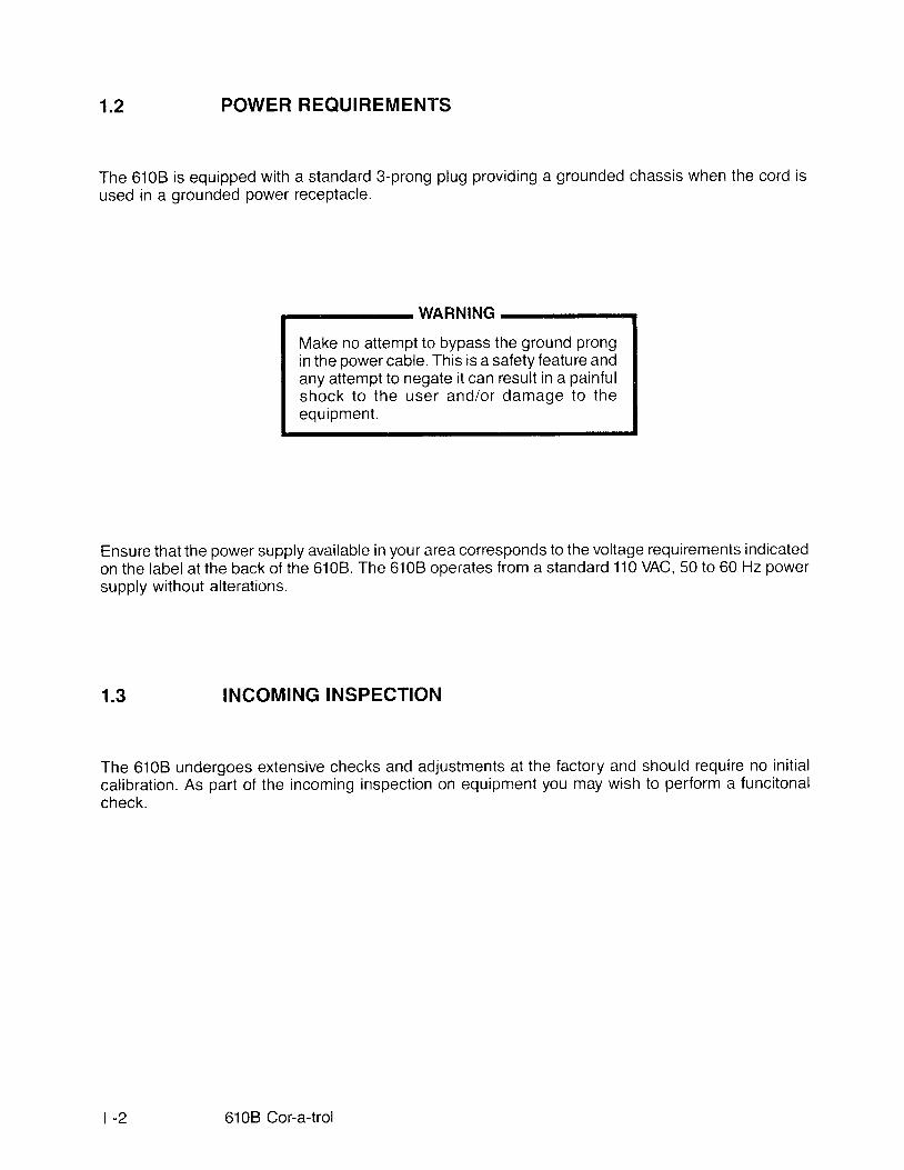
e. ln the METER Section (see Figure 5):
Fl ip the selector switch to the "V" posit ion.Fl ip the range switch to the "0-10 KV" posit ion
Figure 5. Set Controls in METER Section
( 1 )(2)
t - 6 6108 Cor-a-trol

@POWER
@
f. Flip the 6108 POWER switch to the ON posit ion (see Figure 6).
Figure 6. POWER Switch in ON Position
g. Wait thirty seconds and then f l ip the HV switch to the ON posit ion (see Figure 7).
Fioure 7. HV Switch in ON Position
l - 7Section I Instal lat ion
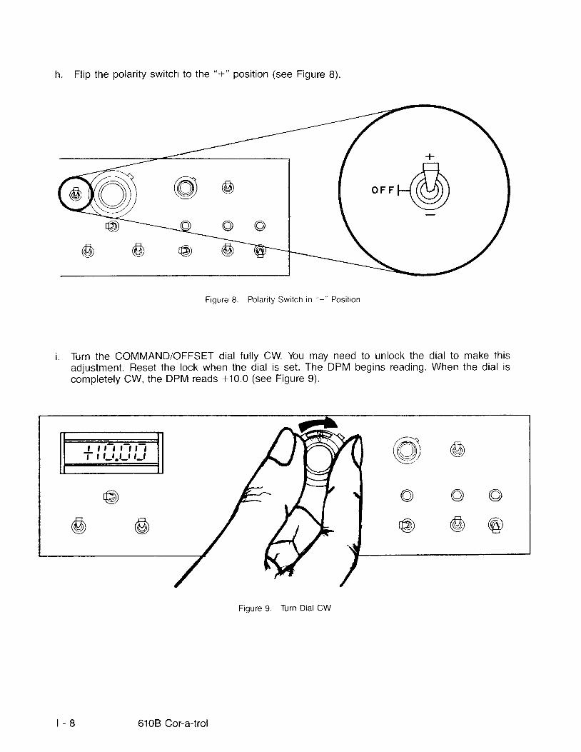
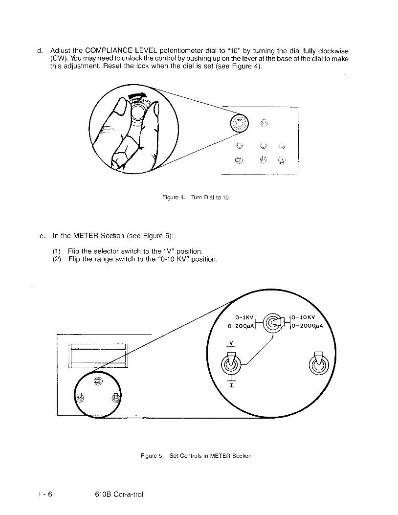
h. Fl ip the polarity switch to the "- l-" posit ion (see Figure B).
Figure 8. Polar i ty Swi tch in "+" Posi t ion
Turn the COMMAND/OFFSET dial ful ly CW. You may need to unlock the dial to make thisadjustment. Reset the lock when the dial is set. The DPM begins reading. When the dial iscompletely CW, the DPM reads +10.0 (see Figure 9).
I t t I t t , IT , t-,.t-, t-l
t - 8 610B Cor-a-trol
Fioure 9. Turn Dial CW
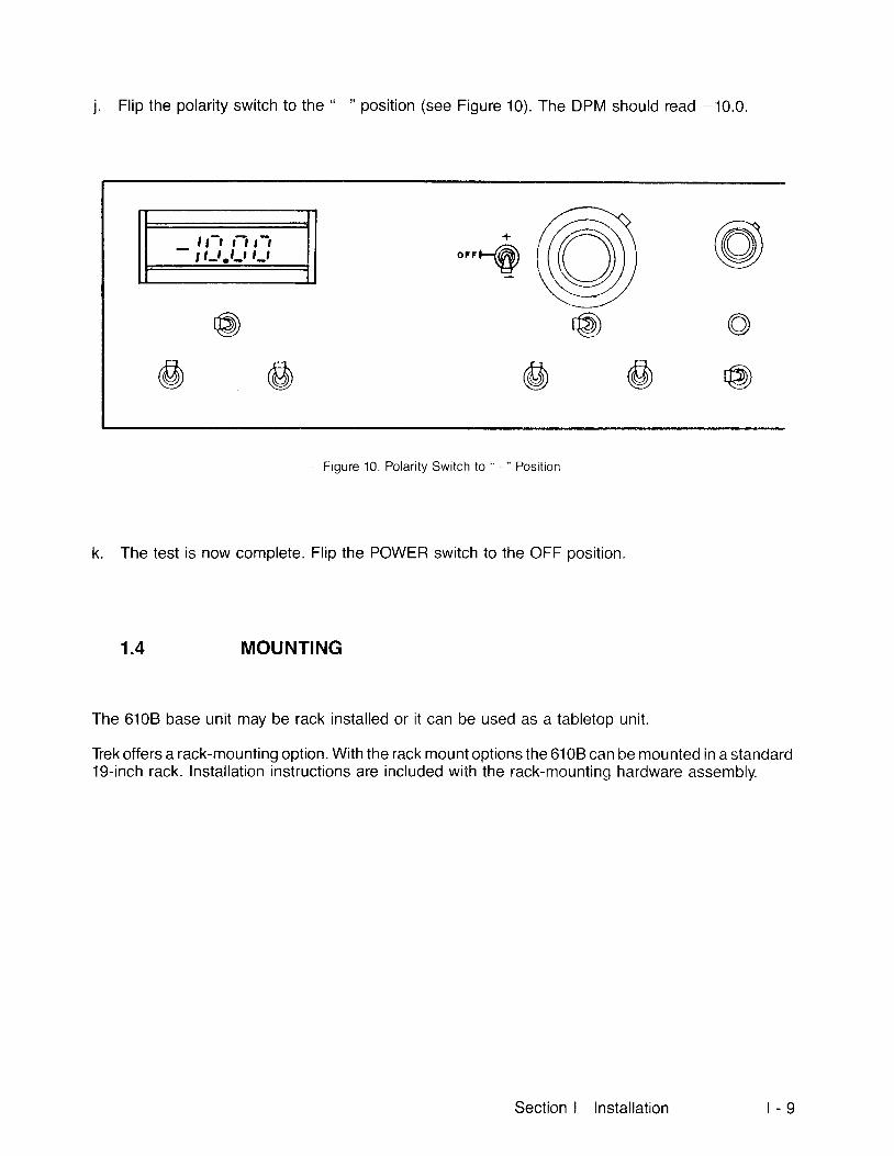
1. Fl ip the polarity switch to the "-" posit ion (see Figure 10). The DPM should read -10.0.
J l , , t t t- t l - t - t - t r- t o"r-@
Figure 10. Polarity Switch to " -" Position
k. The test is now complete.Fl ip the POWER switch to the OFF posit ion.
1 .4 MOUNTING
The 610B base unit may be rack instal led or i t can be used as a tabletop unit.
Tiek offers a rack-mounting option. With the rack mount options the 6108 can be mounted in a standard19-inch rack. Instal lat ion instructions are included with the rack-mounting hardware assembly.
Section I Instal lat ion t - 9
2
SECTION II OPERATION
SET UP
The 6108 is ready for use upon arrival. You may control it as a local unit or operate it in a remote mode.Use only a grounded power source. You may use it as a tabletop unit o4 with a l?ek conversion kit, youmay use it rackmounted.
CONTROLS
The controls on the 610B are fully visible and easy to operate. The receptacles are clearly labeled.
WARNING
This equipment generates high voltage. Readall instructions and warnings before proceed-ing . Use cau t i on when ope ra t i ng theequipment.
2.1
Section ll Operation i l - 1
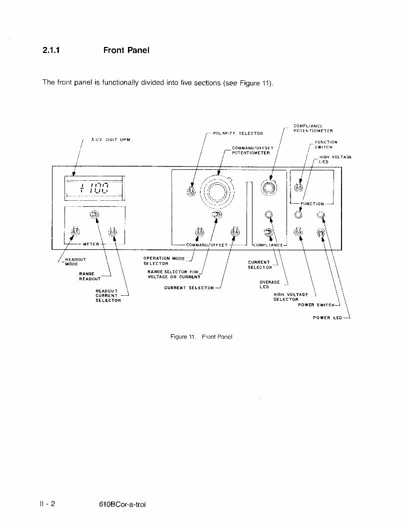
2.1.1 Front Panel
The front panel is functionally divided into f ive sections (see Figure 11).
P O L A R I T Y S E L E C T O R3 I l 2 D I G I T D P M
C O M M A N O / O F F S E TPOTENT IOM ETE R
C O M P L I A N C EP O T E N T I O M E T E R
F U N C T I O NS W I T C H
H I G H V O L T A G EL E D
@6)Y( 6 ) l
r lCOMMAND, /OFFSET
- F U NJC)
C T I O N
fa\)1@)\I \
M E T E R L I A N C E
O P E R A T I O N M O D ES E L E C T O R
RANGE SELEC' IOR FORVOLTAGE OR CURRENT
C U R R E N T S E L E C T O R
Figure 11. Front Panel
C U R R E N TS E L E C T O R
R A N G ER E A D O U T
OVERAG EL E D
R E A O O U TC U R R€ N TS E L E C T O R
H I G H V O L T A G ES E L E C T O R
P O W E R S W T T C I {
P O W E R L E D _ _
| - 2 610BCor-a-trol

2.1.1.1 POWER and HV Switches Section
The POWER switch is a two-posit ion switch, ON and OFE When the POWER switch is in the ONposit ion, the green LED above it is i l luminated indicating that power is applied to the controlcircuits andthe output regulator heater circuit (see Figure 12),
The HV control is a three-position switch (refer to Figure 12). In the ON position it activates the high-voltage power supplies. The red LED i l luminates when the switch is set to ON or when the unit is in theREMOTE mode and pins 3 and 6 of the EXT CONTROL connector are shorted, indicating that high-voltage may be present at the HV OUT connector.
NOTE
Wai t th i r ty seconds af ter act ivat ing thePOWER switch before activating the HVswitch.
@ @H V P O W E R
ffi-@*!}!orrf-
Figure 12. POWER and HV Switches
Section ll Operation i l - 3

2.1 .1 .2 FUNCTION Section
There are three function controls: SUPPLY AMPLIFIEFI, and CONTROLLER.
2 j .1 .2 .1 SUPPLY
In the SUPPI-Y posit ion, the 6108 functions as a precise, adjustable, high-voltage power supply with anadjLrstable current l imit; or as a precise, adjustable current supply with an adjustable voltage l imit (seeFigure 13) .
Fioure '13. Swi tch in SUPPLY Posi t ion
z' .-- '-.-.J
l i \ t ) ) ) t-',,,/
na\
r r { I)l t"!) rg)
@
r$
SUPPLY
AMPLIF IER
C O N T R O L L E R
| - 4 6108 Cor-a-trol

2.1.1.2.2 AMPLIFIER
In the AMPLIFIER mode, output voltage or output current are proportional to a voltage input signalcontrol applied to the 6108 through a rear panel mounted connector (see Figure 14).
FUNCT IONswrrcH
/;_-1((Or)\\\7//
@
@o@
@(Or+
(t)
F igure 14. Swi tch in AMPLIFIER Posi t ion
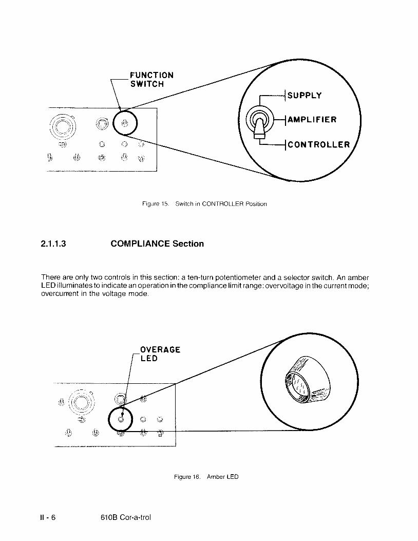
2.1:1.2.3 CONTROLLER
In the CONTROLLER mode, the input configuration is maintained as in the amplif ier mode, while theamplifier's input and feedback parameters are left uncommitted and available for user selection (referto Figure 15).
Terminals for the installation of resistor and/or capacitor elements provide the means for tailoring the610B gain characteristics to your particular requiremenls.
S U PPLY
A M P L I F I E R
CONTROLLER
Section ll Operation i l - 5
FUNCTIONsw tTc H
Figure 15. Swi tch in CONTROLLER Posi t ion
2 .1 .1 .3 COMPLIANCE Section
There are only two controls in this section: a ten-turn potentiometer and a selector switch. An amberLED i l luminates to indicate an operation in the compliance l imit range: overvoltage in the current mode;overcurrent in the voltaqe mode.
OVERAGEL E D
,^\(Jo@)
r6,il\\ \-' ///
t - - ' - - z
w)
+lI l.{l)
SU PPLY
A M P L I F I E R
C O N T R O L L E R
i l - 6 6108 Cor-a-trol
Figure '16. Amber LED

2.1.1.3.1 COM PLIANC E Potentiorneter
The ten-turn COMPLIANCE potentiometer is used to set the l imit value of load current (1, or l .) when theunit is in a voltage mode of operation or to set the l imit value of output voltage when the 6108 is in thecurrent mode of operation (see Figure 17). The dial has a lock at i ts base. To disengage the lock, pushupward, turn the dial to the desired posit ion, and then push downward to engage the lock.
C O M P L I A N C EP O T E N T I O M E T E R
().&, 'A)
Figure 17. COMPLIANCE Potentiometer
2 .1 .1.3.2 Current Limit Selector Switch
This switch determines which current, l , or 1,., is to be l imited when the unit is in a voltage mode (seeFigure 18). l , . is the current which f lows through the rear panel mounted l ' , terminal, while l , is the totalcurrent f lowing in the HV OUTPUT connector.
Figure 18. Current Limit Selector Switch
,,i;-:.t@,(((()))'.:-, :_,/
@) o@(!,)G)
@
C U R R E N TS E L E C T O R L I M I T
,m /rAtr\: \\\ ,/// /(t')
t-: ___nl l - - ' l il t _ - _ _ _ - t ll_--- l
@
Section ll Operation l l - 7

2 .1 .1 .4 COM MANDIOFFSET Section
The COMMAND/OFFSET section has four switches and one potentiometer dial.
2 .1"1.4.1 COM MAN D/OFFSET Potentiometer
This ten-turn potentiometer dial is used to (see Figure 19):
a. Command the ioad voltage when the unit is used as a voltage supply.
b. Command the load current, l , or 1.,, when the unit is used as a current supply.
c. Set the offset voltage when the unit is in the voltage amplif ier or voltage control ler modes.
d. Set the offset current, I , or 1,, when the unit is in the current amplif ier or current control ler modes.
This dial has a lock at i ts base. To disengage the lock, push upward, turn the dialto the desired posit ion,and then push downward to engage the lock.
When in the current supply mode or current amplif ier mode, the output current rs equalto two t imes thedial sett ing value.
EXAMPLE:
In the l , mode:
"*with the pA/KV range switchset to
0-200 pA
ful l potentiometer : 200 pA
"*with the pA/KV range switchset to
0-2000 pA
ful l potentiometer : 2000 pA
In the voltage mode, any value up to 1 KV can be directly selected by the potentiometer dial with thepA/KV range switch set to "0-1KV" and any value up to 10 KV can be directly selected by thepotentiometer dial with the pA/KV range switch set to "0-10KV".
l l - 8 6108Cor -a - t ro l
COMMAND/OFFSETPOTENTIOMETER
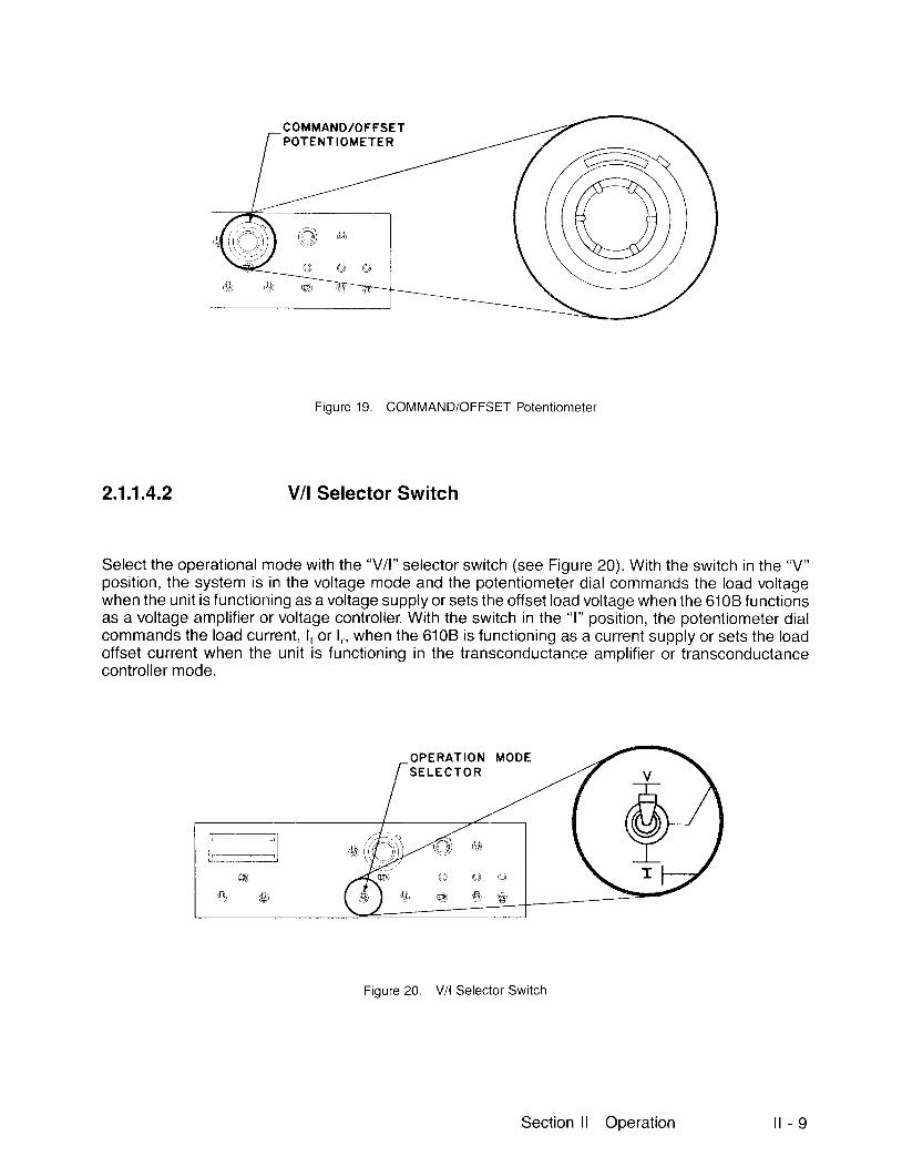
Figure 19. COMMAND/OFFSET Potentiometer
2 .1 .1.4.2 V/l Selector Switch
Select the operational mode with the "V/1" selector switch (see Figure 20). With the switch in the "V"posit ion, the system is in the voltage mode and the potentiometer dial commands the load voltagewhen the unit is f unctioning as a voltage supply or sets the offset load voltage when the 6108 f unctionsas a voltage amplif ier or voltage control ler. With the switch in the "1" posit ion, the potentiometer dialcommands the load current, l , or 1,., when the 6108 is functioning as a current supply or sets the loadoffset current when the unit is functioning in the transconductance amplif ier or transconductancecontrol ler mode.
Figure 20. Vil Selector Switch
OPERATIONS E L E C T O R
di
Q ' O
'.@1 ,,A)
o@
Section ll Operation i l - 9
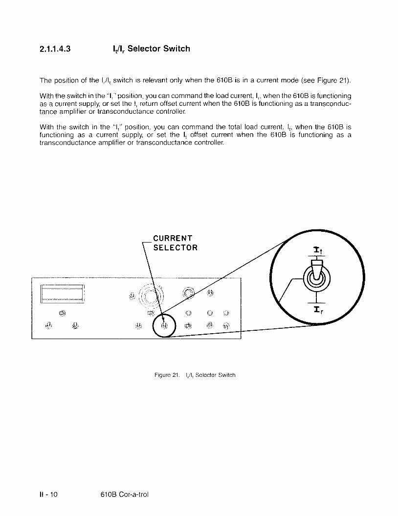
2.1.1.4.3 l,/1, Selector Switch
The posit ion of the l , . /1, switch is relevant only when the 6108 is in a current mode (see Figure 21).
With the switch in the "l ," posit ion, you can command the load current, 1,-, when the 6108 is functioningas a current supply, or set the l . return offset current when the 610B is functioning as a transconduc-tance amplif ier or transconductance control ler.
With the switch in the "1," posit ion, you can command the total load current, 1,, when the 6108functioning as a current supply, or set the l , offset current when the 6108 is functioning astransconductance amplif ier or transconductance control ler.
C U R R E N TS E L E C T O R
Figure 21 . l,/1, Selector Switch
iscL
_ll- - t lt i--_1J @
C I o@ ' o
i l - 1 0 6108 Cor-a-trol

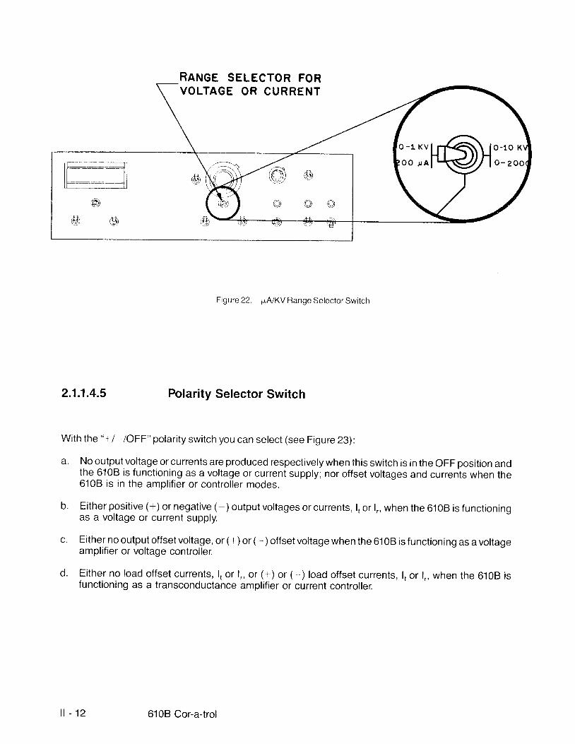
21.1.4.4 ILA/KV Range Selector Switch
The pA/KV range selector switch (see Figure 22):
a. Determines the maximum output voltage at 1 KV or 10 KV when the unit is functioning as a voltagesupply.
b. Selects the ful l scale load current, l , or 1'. , at 200 pA or 2,000 pA when the 6108 is functioning as acurrent supply.
c. Selects the amplif ier gain and the maximum output offset voltage when the 6108 is functioning as avoltage amplif ier:
1. "0 - 1 KV" posit ion equals 100 volts output per volt input.
2. "0 - 10 KV" posit ion equals 1,000 volts output pervolt input.
d. Determines the transconductance gain and the maximum load offset current, l , or 1,, when the unitis functioning as a transconductance amplif ier:
1. "0 - 200 pA" posit ion equals 20 pA output per volt input.
2. "0 - 2000 pA" posit ion equals 200 pA output per volt input.
e. Selects a 10 to 1 voltage scale factor of voltage gain and the maximum output offset voltage whenthe 6108 is functioning in the voltage control ler mode. Voltage control ler gain and maximumvoltage offsets are alterable by your component selection.
f. Selects a 10 to 1 scale factor of current gain and maximum output offset current when the 6108 isoperating in the transconductance control ler mode. Control ler transconductance and load offsetcurrents are alterable by your component selection.
Section l l Operation l l - 11
RANGE SELECTOR FORVOLTAGE OR CURRENT
Figure22. pA/KV Range Selector Switch
2 .1 .1.4.5 Polarity Selector Switch
With the "+l- laFF" polarity switch you can select (see Figure 23):
a. No outplt voltage or currents are produced respectively when this switch is in the OFF posit ion andthe 6108 is functioning as a voltage or current supply; nor offset voltages and currents when the6108 is in the amplif ier or control ler modes.
b. Either posit ive (+) or negative ( -) output voltages or currents, l , or 1., when the 610B is functioningas a voltage or current supply.
c. Either no output offset voltage, or (+) or (- ) offset voltage when the 6108 is functioning as a voltageannplifier or voltage controller.
d. Either no load offset currents, l , or 1,., or (+) or (-) load offset currents, l , or 1., when the 6108 isfunctioning as a transconductance amplif ier or current control ler.
o -1 KV t r*<\, \ lO-tO r<oo rAl - ' (SZ/ . / lo-z
@ e l@ @ o
| - 1 2 6108 Cor-a-trol
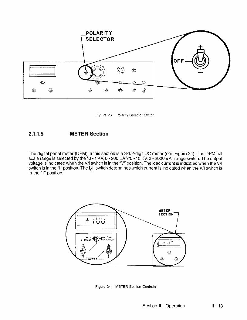
POLAR I TYSE LE CTO R
f:]tt_------lll t t l|-=------l
@
Figure 23. Polarity Selector Switch
2 .1 .1.5 METER Section
The digital panel meter (DPM) in this section is a 3-1/2-digit DC meter (see Figure 24).The DPM ful ls c a l e r a n g e i s s e l e c t e d b y t h e " 0 - 1 K V 0 - 2 0 0 p u A " l " O - 1 0 K V 0 - 2 0 0 0 p A " r a n g e s w i t c h . T h e o u t p u tvoltage is indicated when the V/l switch is in the "V" posit ion. The load current is indicated when the V/lswitch is in the "l" posit ion. The l, /1,- switch determines which current is indicated when the V/l switch isin the "1" posit ion.
Figure 24. METER Section Controls
M E T E RS E C T I O N
I t-t t-tt l_1 t_l
O - 1 K VO - z O O x A
Section ll Ooeration l l - 1 3
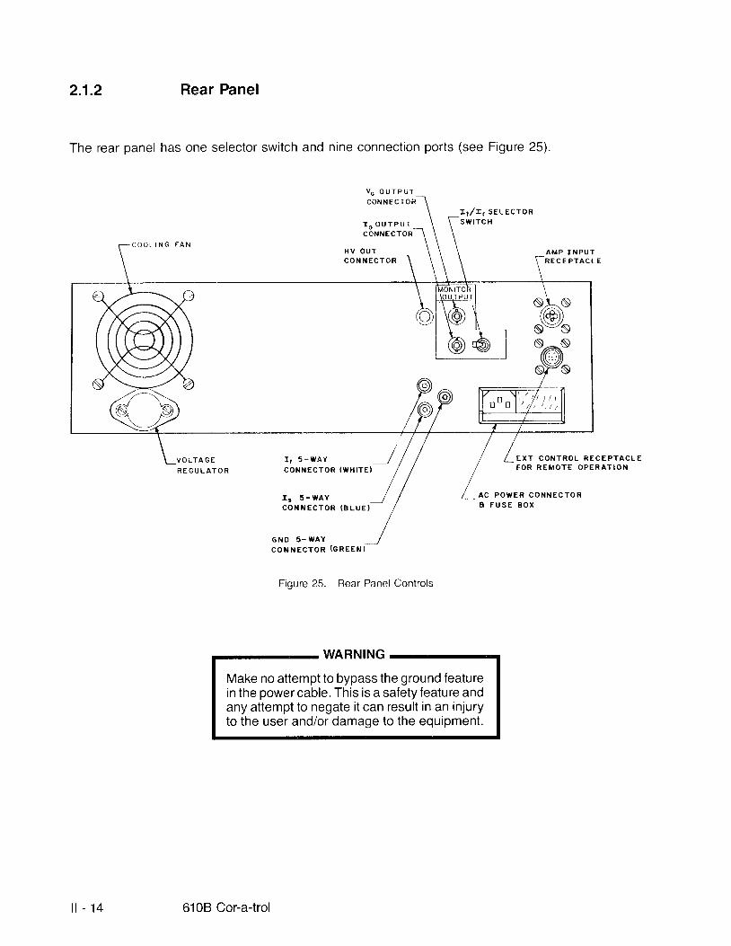
21.2 Rear Panel
The rear panel has one selector switch and nine connection ports (see Figure 25)
C O N N E C T O R
r o o U T P U TI r , / I r S E L E C T O Rs w t r c H
C O O L I N G
C O N N E C T O R
H V O U T
V O L T A G ER E G U L A T O R
C O I { N E C T O R
C O N N E C T O R ( c R E E N )
Figure 25. Rear Panel Controls
WARNING
Make no attempt to bypass the ground featurein the power cable. This is a safety feature andany attempt to negate it can result in an injuryto the user and/or damage to the equipment.
A M P I N P U TR E C E P T A C L
E X T C O N T R O L R E C E P T A C L EF O R R E M O T E O P E R A T I O N
A C P O W E R C O N N E C T O RA F U S E B O X
tl
v o o U T P U T
ST-N(@)N:S*6,*sYs
:j^:.'"""''1,I ' 5 - W A YC O N N E C T O R I W H I T E )
C O N N E C T O R ( B L U E }
G N D 5 - W A Y
1 4 610B Cor-a-trol
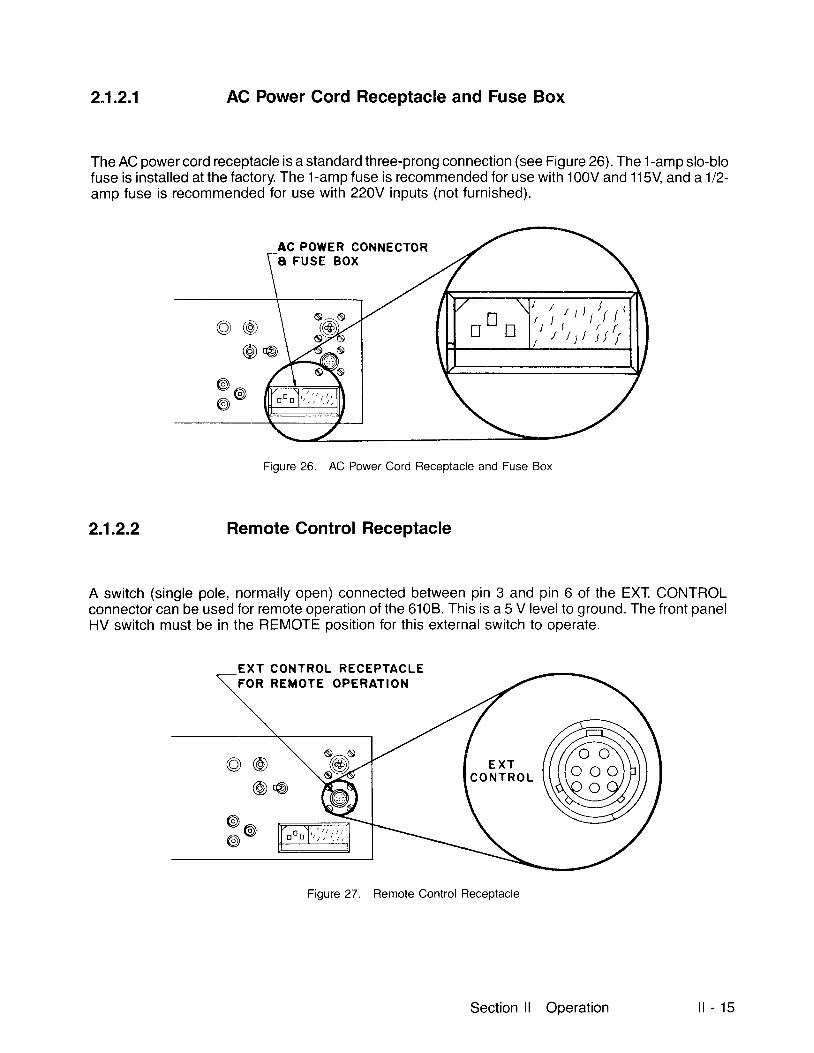
2"1.2.1 AC Power Cord Receptacle and Fuse Box
The AC power cord receptacle is a standard three-prong connection (see Figure 26). The 1-amp slo-blofuse is installed at the factory. The 1-amp fuse is recommended for use with 100V and'115V and a112-amp fuse is recommended for use with 220V inputs (not furnished).
Figure 26. AC Power Cord Receptacle and Fuse Box
2.1.2.2 Remote Control Receptacle
A switch (single pole, normally open) connected between pin 3 and pin 6 of the EXT CONTROLconnector can be used for remote operation of the 6108. This is a 5 V level to ground. The front panelHV switch must be in the REMOTE posit ion for this external switch to operate.
CONTROL RECEPTACLEREMOTE OPERATION
@ @@ o
Figure 27. Remote Control Receptacle
E X TFOR
AC POWER CONNECTORA FUSE BOX
/ ' r ' r ) t l t t t
Section ll Operation l l - 1 5

2.1.2.3 AMP INPUT Receptacle
The AMP INPUT receptacle is to connect an external signal to the 6108 (see Figure 28):
a. Noninvert ing operation - input signal to pin 1, common to pin 3, short pins 2 and 3.
b. Invert ing operation - input signal to pin 2, common to pin 3.
c. Differential operation - input signal between pins 1 and 2, common to pin 3.
A M P I N P U TR E C E P T A C L E
a) @r@ o
9 o€,
F igure 28. AMP INPUT Receptacle
Fiqure 29. Pin Connections
O ) N O N I N V E R T I N G I N P U T b } I N V E R T I N G I N P U T C ) D I F F E R E N T I A L I N P U T
l l - 1 6 6108 Cor-a-trol

2.1.2.4 OUTPUT Section
The OUTPUT section has two BNC receptacles, Vo and lo, and an l,/i,- selector switch. Thesereceptacles and switch are for your convenience in the use of other read-out equipment, i .e., printers.
2 j .2 .4 .1 Vo MONITOR OUTPUT Connector
The Vo MONITOR OUIPUT connector is a BNC outlet for monitoring t lre 6108 output voltage at a ratioof 1,000 to 1 (10 KV : 10 V) (see Figure 30).
vo oUTPUTCONNECTOR
s^N/,ai\\-dl/
S:Ns^s
Figure 30. Vo MONITOR OUTPUT Connector
Section l l Operation l l - 1 7

2.1.2.4.2 lo MONITOR OUTPUT Connector
The loMON|TOROUTPUTconnec to r i saBNCou t le t fo rmon i to r i ng l , l l , ( 2000pAequa ls10V FSo f l , o rl , current ) (see F igure 31) .
Figure 31 . lo MONITOR OU-TPUT Connector
2.1.2.4.3 l,/1, Monitor Selector Switch
The l, /1. switch selects which current, l , or 1., is to be monitored at the lo monitor connector (see Figure32) .
Figure 32. l,/1, Monitor Selector Switch
ro ouTPt TC O N N E C T O R
L t / T t S E L E C T O Rsw lTcH
*@.,
i l - 1 8 6108 Cor-a-trol
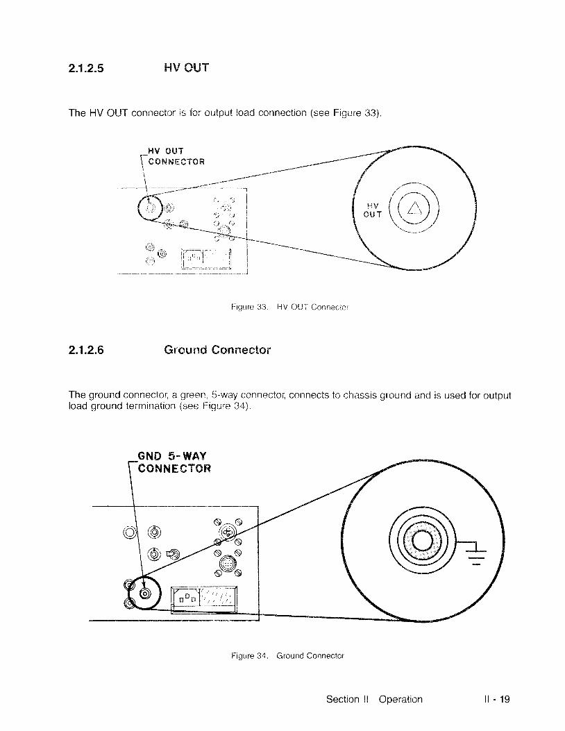
2.1.2.5 hIV CUT
The HV OI,JT connecior is for cutput ioad connection (see Figure 113)
H V O U T
fcorururcron
n r IO i ' , , , n '
,: l J l
FigLire 3i1. HV C)Ul- Connec;icr
2 .1.2.6 Ground eonnector
The ground connectol a green, S-way connector, connects to chassis ground and !s used for outprltload ground termination (see FigLire 3,1).
Figure 34. Ground Connector
GND 5.WAYCONNHCTOR
Section l l Operation l l - 1 9

2.1.2.7 l, Connector
The l, connector, a white, S-way connectot ' , is used for terminating the output load when operating the610B in the l . mode (see Figure 35) .
Figure 35. I, Connector
2.1.2.8 lu Connector
The l= connector, a blue, S-way connector, provides a termination for electrophotographic Coratronshielding electrodes connected to the 6108 (see Figure 36). When this connection is used, any currentf lowing to the l" connector is not measured and control led while operating in the l, mode. ln this mode, l ,becomes a true measure of electrophotographic surface current and can be control led to highaccuracy by the 6108, thereby providing electrophotographic surface current regulation into groundedsurfaces.
r r 5-WAYCONNECTOR
rs s-wAYCONNECTOR
@@ o
l l - 2 0 610B Cor-a-trol
Figure 36. lu Connector
2.2 ROUTINE OPERATION
The 6108 can operate in three modes with a great many variations within those three modes. Themodes are: SUPPLY AMPLIFIER, and CONTROLLER. Random control values were chosen toillustrate a routine operation in each mode, and are to be used as a guide only.
2.2.1 Supply Mode
In the SUPPLY posit ion, the 6108 can function either as a voltage supply with an adjustable currentl imit, or as a current supply with an adjustable voltage l imit.
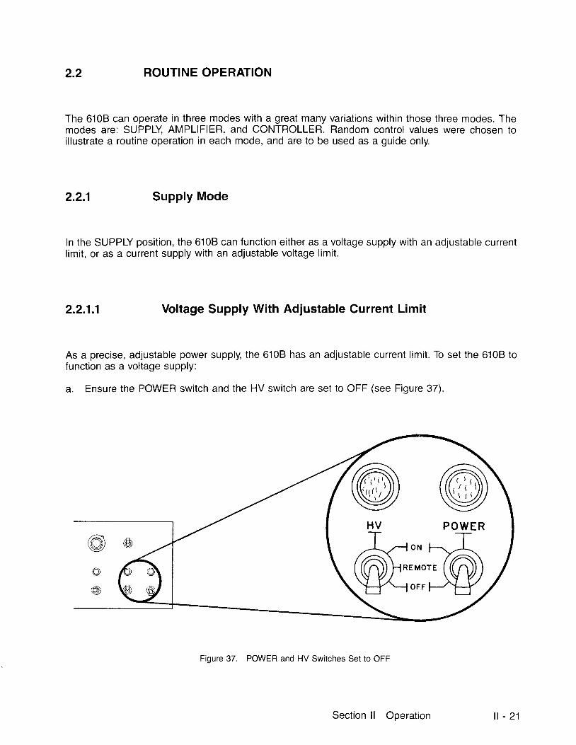
2 .2.1.1 Voltage Supply With Adjustable Current Limit
As a precise, adjustable power supply, the 610B has an adjustable current l imit. To set the 610B tofunction as a voltage supply:
a. Ensure the POWER switch and the HV switch are set to OFF (see Figure 37).
Figure 37. POWER and HV Switches Set to OFF
@ @HV POI,VER
Section l l Operation l t - 2 1
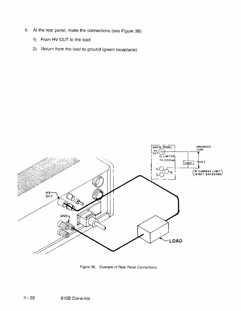
b . At the rear panel, make the connections (see Figure 3g):
1) From HV OUT to the load
2) Return from the load to ground (green receptacle)
Figure 38. Example of Rear Panel Connections
t rc
G R O U N O E DLOAD
/ t r cunnex r r - rn r r \\ t s NoT ExCEEDED, /
l l - 2 2 6108 Cor-a-trol
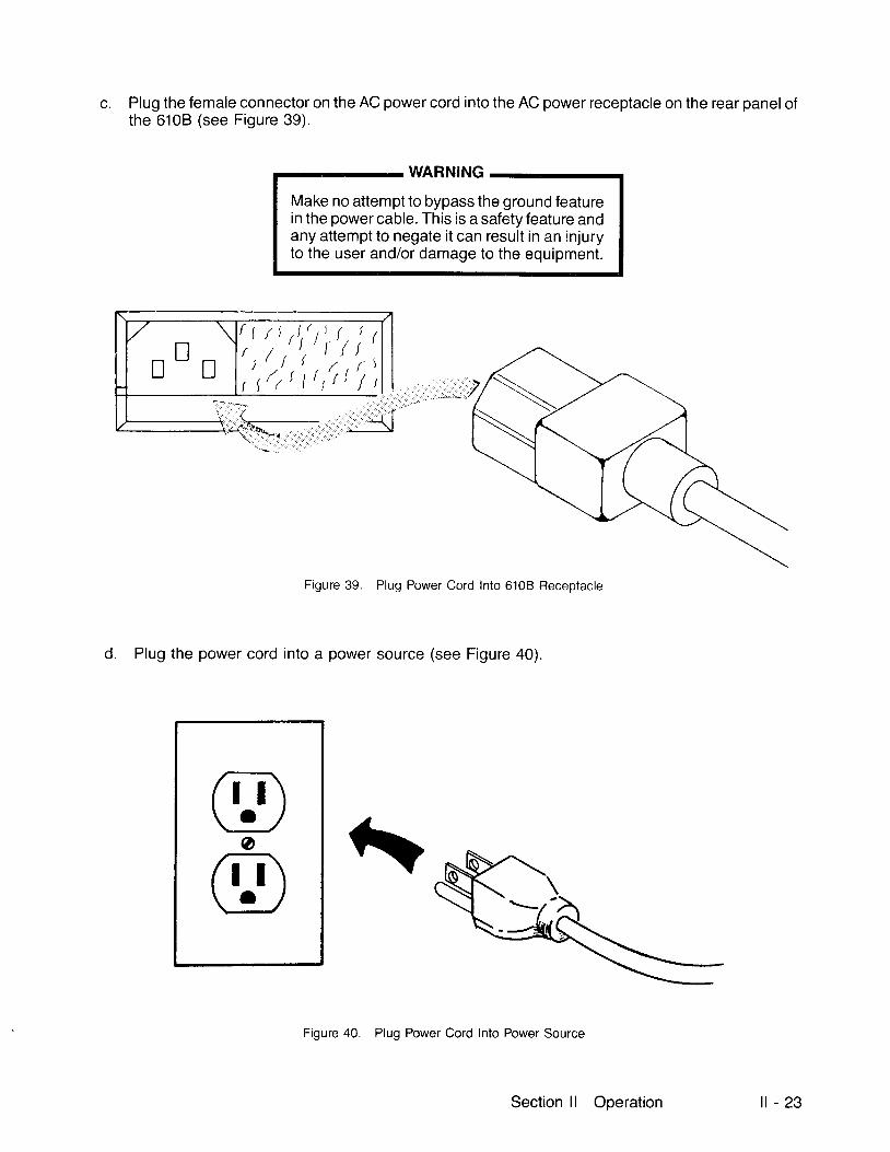
c. Plug the female connector on the AC power cord into the AC power receptacle on the rear panel ofthe 6108 (see Figure 39).
WARNINGMake no attempt to bypass the ground featurein the power cable. This is a safety feature andany attempt to negate it can result in an injuryto the user and/or damage to the equipment.
f 1
Jt \
t/t ,"','t r)t l,
/ r l l t , ' r l ' 1
,S*,.,,"-.,
Figure 39. Plug Power Cord Into 610B Receptacle
d. Plug the power cord into a power source (see Figure 40).
Figure 40. Plug Power Cord lnto Power Source
Section ll Operation i l - 2 3
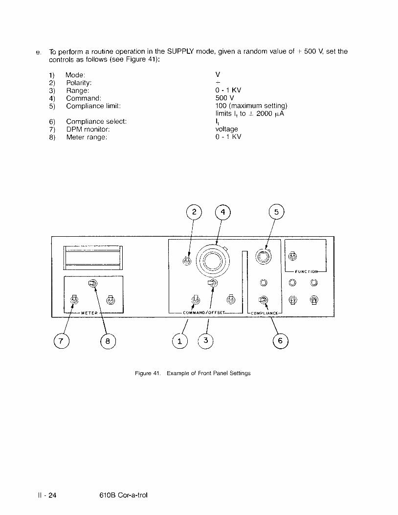
e. To perform a routine operation in the SUPPLY mode, given a random value of + 500 V set thecontrols as fol lows (see Figure 41):
1 )2)3)4)5)
ol7)B)
Mode:Polarity:Range:Command:Compl iance l imi t :
Compliance select:DPM monitor:Meter range:
Vf
O - 1 K V500 v100 (maximum set t ing)l imits l , to t 2000 p"AItvoltageO - 1 K V
Figure 41 . Example of Front Panel Settings
| - 2 4 6108 Cor-a-trol
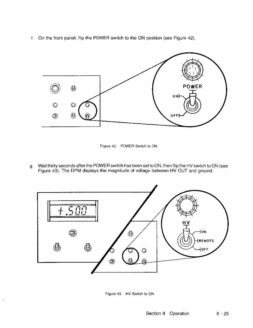
f . On the front panel, f l ip the POWER switch to the ON posit ion (see Figure 42).
Fioure 42. POWER Switch to ON
g. Wait thirty seconds after the POWER switch has been set to ON, then flip the HV switch to ON (seeFigure 43). The DPM displays the magnitude of voltage between HV OUT and ground.
Figure 43. HV Switch to ON
@POWER
@
A-t"-@U::,'.
II .:; tJt_l
Section l l Operation l l - 2 5
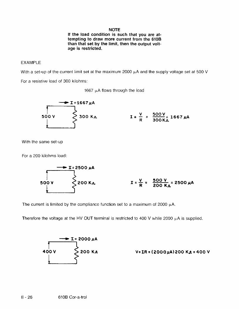
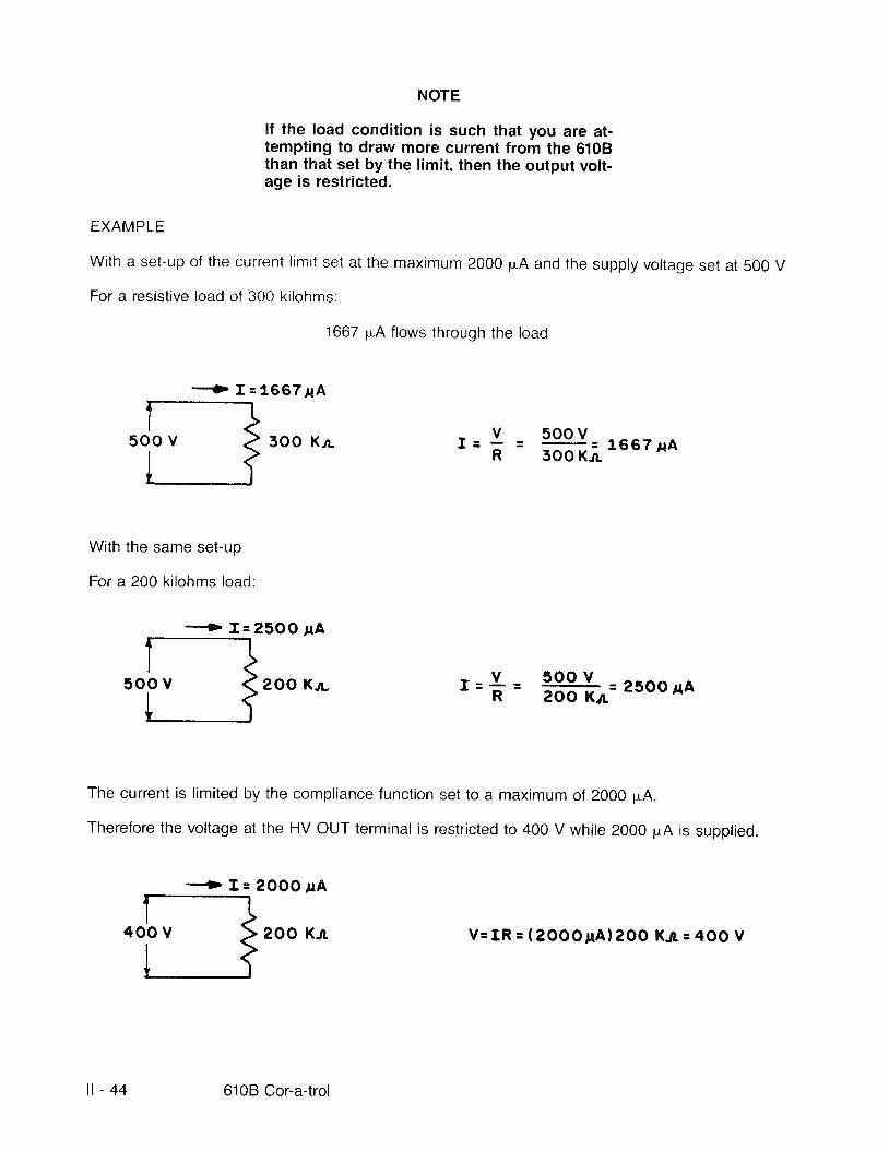
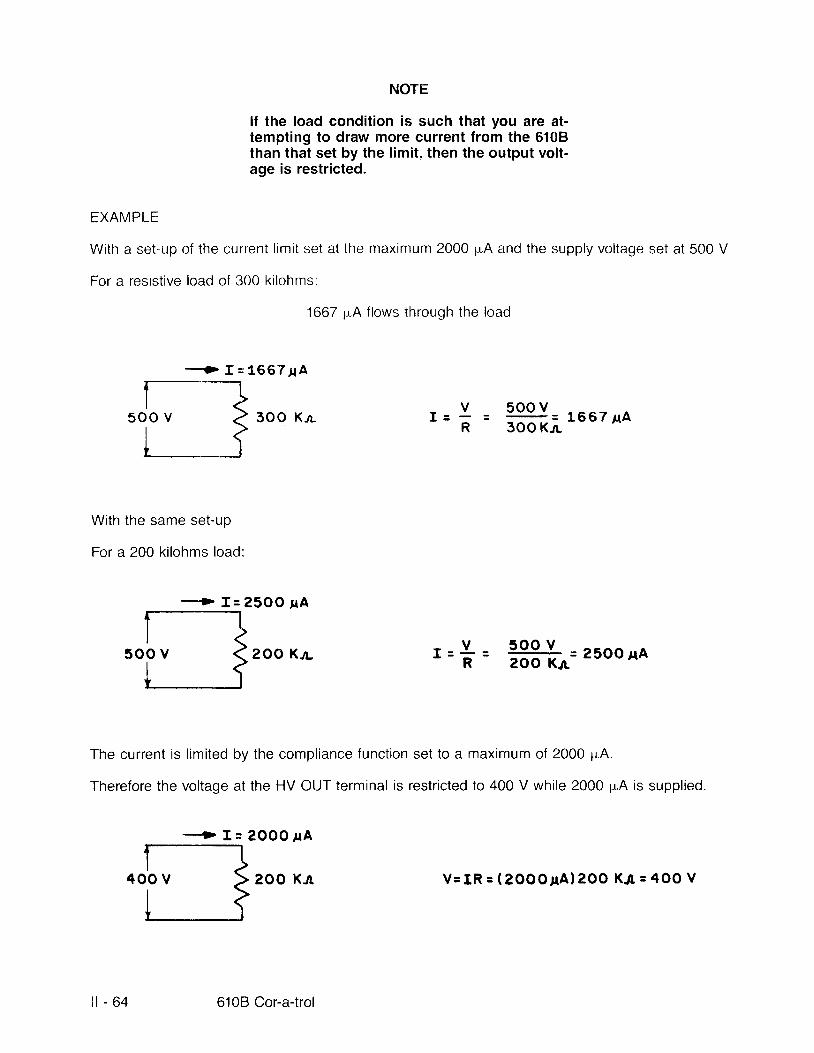
NOTElf the load condition is such that you are at-tempting to draw more current from the 6108than that set by the limit, then the output volt-age is restricted.
EXAMPLE
With a set-up of the current l imit set at the maximum 2000 pA and the supply voltage set at 500 V
For a resist ive load of 300 ki lohms:
1667 pA f lows through the load
- - - r I s1667 lA
3 O O K a I : 500 v3OO Kn
1 6 6 7 t A
With the same set-up
For a 200 ki lohms load:
- '> f :25OO rA
2OO K.n- 500 v = 2 5 O O n A2OO Krr
The current is l imited by the compliance function set to a maximum of 2000 pA.
Therefore the voltage at the HV OUT terminal is restricted to 400 V while 2000 pA is supplied.
+ I = 2 O O O I A
200 KJr
VR
, - - l L -4 - R
-
l l - 2 6 610B Cor-a-trol
V = I R : ( ? O O O I A ) 2 O O K 4 = 4 O O V

2.2.1.2 Current Supply With Adiustable Voltage Limit
ln the current SUPPLY mode, the control led current may be either the total output current measured atthe HV OUT terminal (1, total current), or the current returning to the l, terminal (returned current).
2.2.1.2.1 Current Supply l,. Regulated
Control of the l , is usefui i f you want to regulate a single, ungrounded current path in the presence ofmult iple loads on the output of the 6108. l f l . . is the control led quantity, this current must be returned intothe white l , terminal on the rear panel.
The setup for operation in this mode with a given set of random values is as fol lows:
a. Ensure the POWER switch and the HV switch are set to OFF (see Figure 44).
Figure 44. POWER and HV Switches to OFF
@ @H V P O W E R
Section ll OPeration | - 2 7

b. At the rear panel, make the connections (see Figure 45):
From the HV OUT receptacle to the load
Return the load to the l. receritacle.
LOAD
Figure 45. Sarnple Rear Panel Hook-up l , Regulated
c. Plug the female connector on the AC power cord into the AC power receptacle on the rear panelofthe 6108 (see Figure 46) .
WARNINGMake no attempt to bypass the ground featurein the power cable. This is a safety feature andany attempt to negate i t can result in an injuryto the user and/or damage to the equipment.
1 )
2 \
[sr\c Nl r u ( ,I O r l T \ '
NErlI
l l - 2 8 6108 Cor-a-trol
'rt ,':r: 1,,' ,l ,,,,
Figr-ire 46. Plug Power Ccrd Into 6108 Receptacle
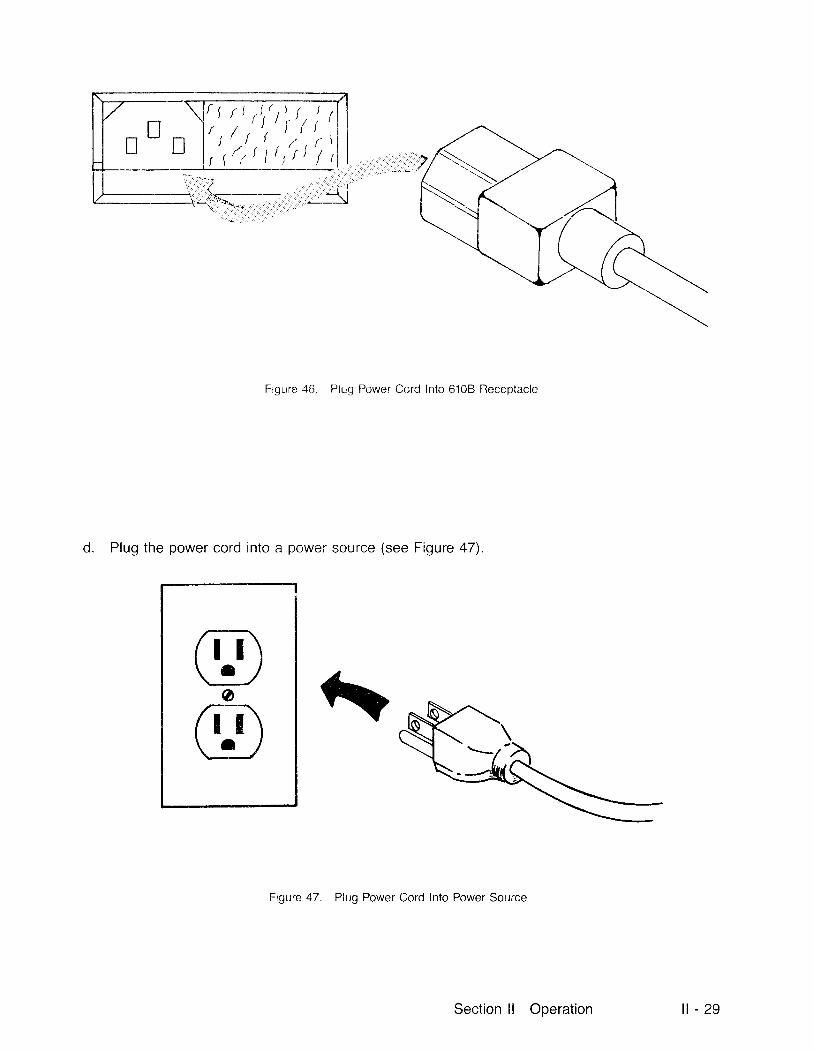
d. Plug the power cord into a power source (see Figure 47)"
Figure 47. Plug Power Cord Into Power Source
hrrr\\ " _ , /o6T\\_1-l
Section ll Operation l l - 2 9

A To perform a current operation in the l, , SUPPLY mode, given a random value of + 400 pA, set thecontrols as fol lows (see Figure 48):
1a) Contro l ledquant i ty :1 b )2) Polarity:3) Range:4) Command:5) Compl iance l imi t :
6a) DPM rnonitor.6b)7) Meter range:
Il ,+0 - 2000 pA20 (400 pA)B0 (18000 V, l imit ing the voltage output atthe HV OUT connector.)| (current) f lowing through 6bl , terminal0 - 2000 pA
t r l E T E R
Figure 48. Example of Front Panel Settings
i l - 3 0 6108 Cor-a-trol
EXAMPLE
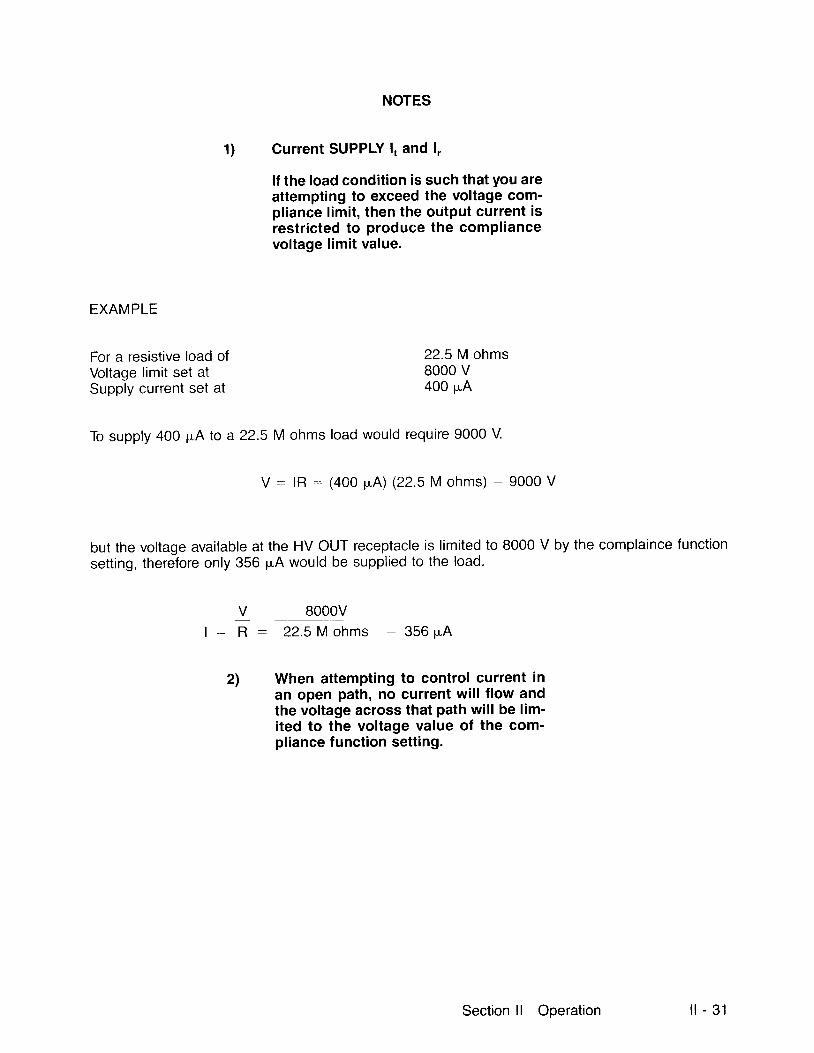
For a resistive load ofVoltage limit set atSupply current set at
NOTES
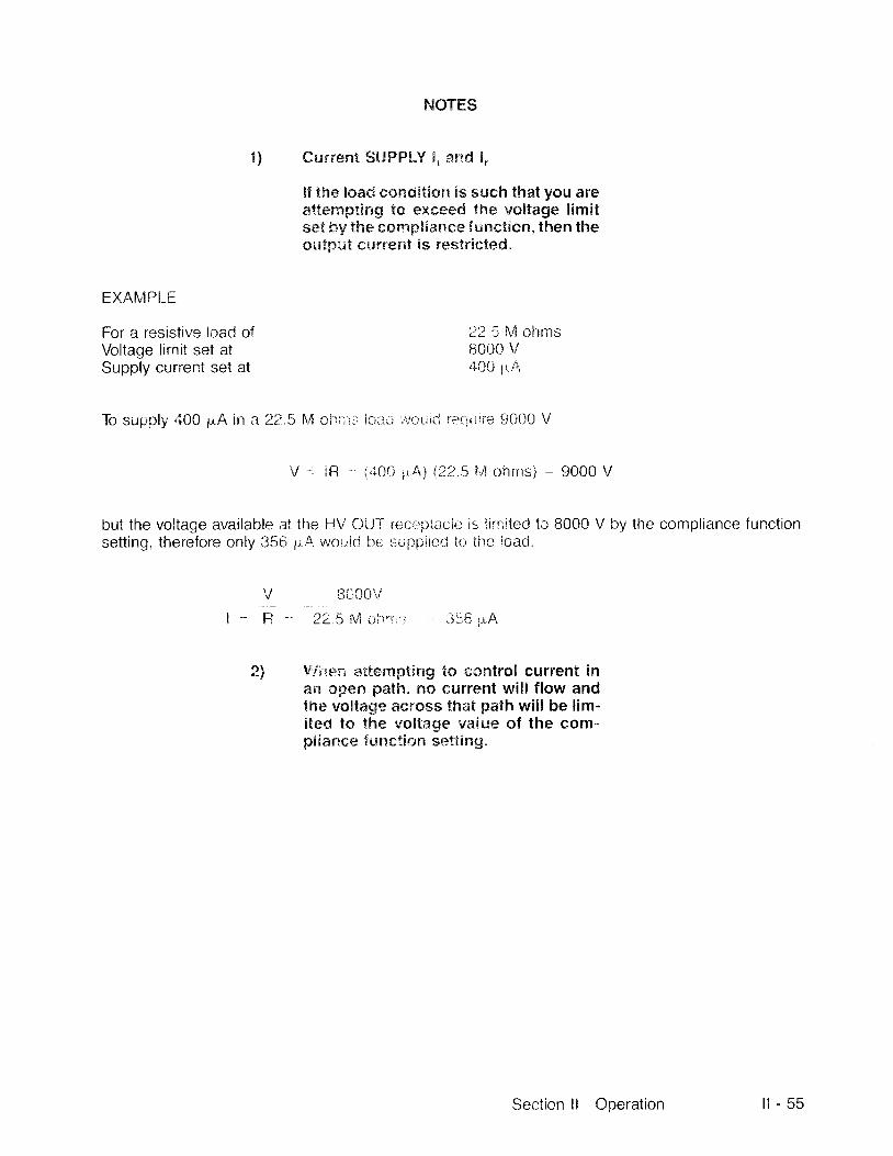
1) Current SUPPLY l, and l,
lf the load condition is such that you areattempting to exceed the voltage com-pliance limit, then the output current isrestricted to produce the compliancevoltage limit value.
22.5 M ohms8000 v400 p"A
To supply 400 pA to a 22.5 M ohms load would require 9000 V.
V : lR : (400 p.A) (22.5 M ohms) : 9000 V
but the voltage available at the HV OUT receptacle is limited to 8000 V by the complaince functionsett ing, therefore only 356 pA would be supplied to the load.
Y lqqoy_l : R 2 2 . 5 M o h m s - 3 5 6 u . A
2) When attempting to control current inan open path, no current wil l f low andthe voltage across that path will be lim-ited to the voltage value of the com-pliance function setting.
Section l l Operation l l - 31

f . On the front panel, f l ip the POWER switch to ON (see Figure 49).
Figure 49. POWER Switch to ON
g Wait thirty seconds after the POWER switch has been set to ON, then f l ip the HV switch to ON (seeFigure 50). The DPM displays the 400 pA f lowing in the external load if the 8000 V l imit is notexceeded.
@POWER
@
@H V
@, I l , - , f - l
T -t t_,,_t
| - 3 2 6108 Cor-a-trol
Figure 50. HV Switch to ON

2.2.1.2.2 Gurrent Supply l , Regulated
lf l , is control led, the load current can be returned to chassis ground or to the l, , terminal. The l. terminalon the rear panel al lows the return of an unmonitorecl current path when l, is the control led current. Thesetup for operation in this rnode with a qiven set of random values is as fol lows:
a. Ensure the FOWER switch and the HV switch are set to the OFF posit ion (see Figure 51).
Figure 51 . POWER and l-lV Switches to OFF
@H V
ffi@P O W E R
Section l l Operation i l - 3 3
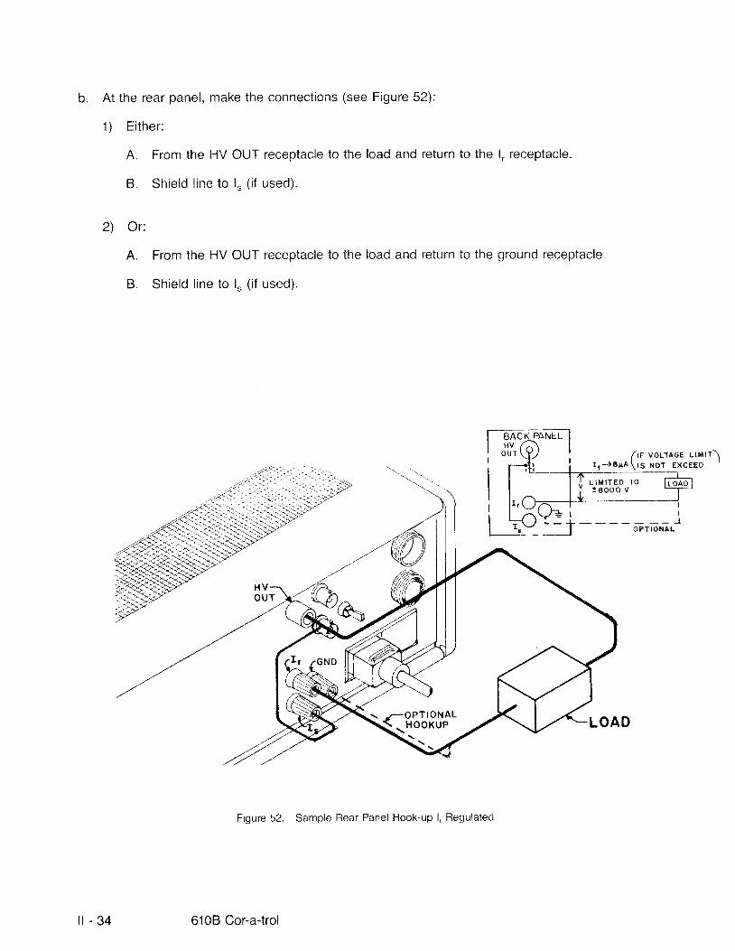
b. At the rear panel, make the connections (see Figure 52):
1) E i ther :
A. From the HV OUT receptacle to the load and return to the l, receptacle.
B. Shie ld l ine to l " ( i f used) .
2) Or:
A. From the HV OUT receptacle to the load and return to the ground receptacle.
B. Shield l ine to l " ( i f used).
\'i'
Figure 52. Sample Rear Panel Hook-up l, Regulated
frr vourrce l lt l t)I t - ) 6 rA \ rS xo t EXCEED
L I M I T E D T O: 8 0 0 0 v
{:g""l8,}l'
i l - 3 4 6108 Cor-a-trol
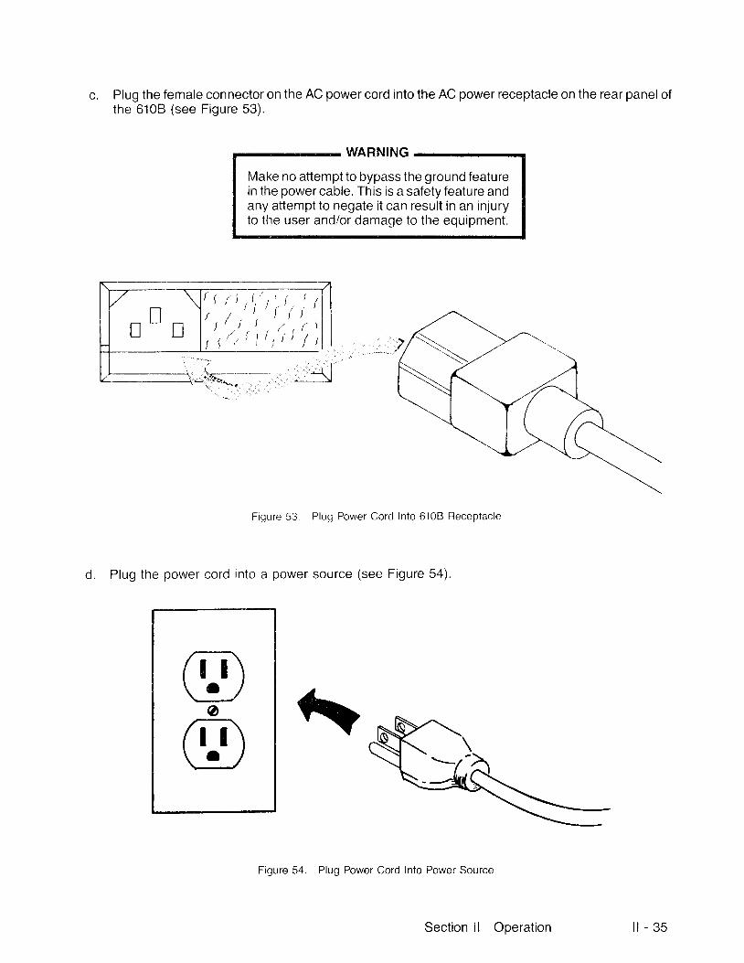
Plug the female connector on the AC power cord into the AC power receptacle on the rear panelofthe 6108 (see Figure 53) .
WARNING
Make no attempt to bypass the ground featurein the power cable. This is a safety feature andany attempt to negate i t can result in an injuryto the user and/or damage to the equipment.
t" ,t')r' |','
'
Figure 53. Pluq Power Cord Into 6108 Receptacle
d. Plug the power cord into a power source (see Figure 54).
Figure 54. Plug Power Cord Into Power Source
' i , '/ , r \i ) / r
frT\\!-/oatT\\-U
Section l l Operation i l - 3 5
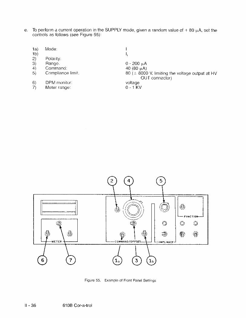
e. To perform a current operatron in the SUPPLY mode, given a random value of + B0 pA, set thecontrols as fol lows (see Figure 55):
1a) Mode:1 b )2) Polarity:3) Rang;e:4) Command:5) Cornpl iance l imi t :
6) DPM moni tor :7) Meter range"
II r+0 - 2 0 0 p A 0 (80 plA)B0 (t 8000 V l imit inq the voltage output at HV
OUT connector)voltage0 . 1 K V
Figure 55. Example of Front Panel Settings
l l - 3 6 6108 Cor-a-trol
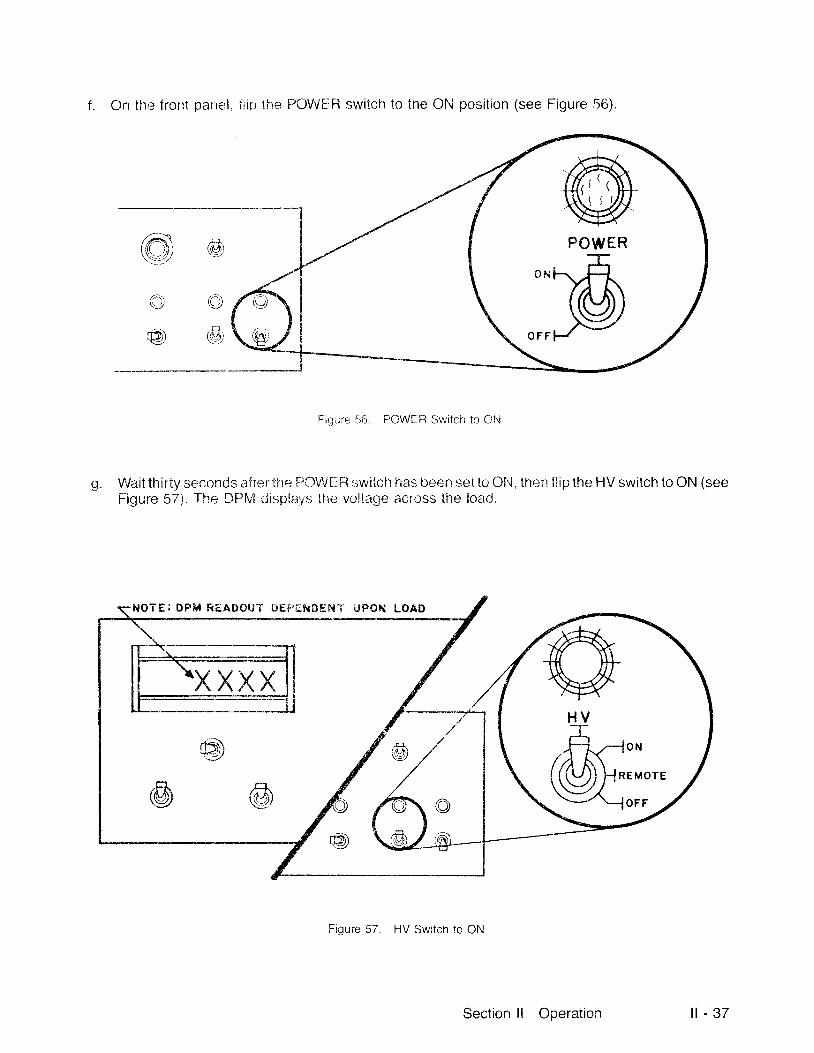
f . On the frorrt parrel, t i ip i . fre PCWE Fi switch to the ON posit ion (see Figure 56).
(,m\,r,\\ -r.J\::-_:/
r^:\t:rz
@)
rl1i\:.7
,cl.t'rt,f'l\:.:!4./
Fiqrre 516. POWER Switcir to 0N
g Wait thirty seconds af tel tne PO$i t ' :R switch has Lreen $et tcr Ohl, then f l ip the HV switch to ON (seeFigure 57). The DFlt ' ! r; ispl:rVS the voltage across the load.
TEI DPM READ€)I jT i lE$' i I${9EF{"t ' l . tPON I-OAD
Figure 57. HV Switch to ON
@POWER
I
/ t t \t ,tt f\ l I
ffir-t v.H-*.@h
Section l l Operation l l - 3 7

2.2,2 Ampli f ler Mode
In the Ah,aPL"lFlER rirodr*, the 6"1011 has,; i lher a :;electa.ble, f ixed voltage gain of 100VlV or 1000VA/, or i thas a selectable, f ixect tr; lrrscclnrjurctance gain c;f 20 pA outlV in or 200 uA outiV in. In the Al/PLIFIERmode, the COMMANDiOFFSF'l- potentiorneter dial functions .rs an offset ( r ). ( ) or OFF command tooffset the output voltage oi 'curre nl f rc;rn zerr:. The input coritroi signalthen varies the output around thisoffset value.
lf l , is the clntantity selei:terj . tht,: i-", treni rviu .t hr,r returned inlc tf ir : l , terrninal on the rearr panel. When l. isthe quantity selected anrJ the clrf foi l l paih ,Joesir ' t inclLrde the l, terrninai, the voltage appearing at theHV OUT terminal wil l Eo to merximurn clutp;irtr voltage set by tfre 66'11'p;lunce l imit. l f l , is the quantityselected, the current may be returned to chassis cl iound or the l, terrnirral.
Connect the input signal into the Al\4P iNlPiJl- receptacle on the rear panel (see Figure 58):
a. noninver t ing input - - input s ignal tc i p in 1. comrnon to p in 3, shor t p ins 2 and 3.
b. invert ing input __ input sigi ial t ' : pin 2, cornmorr to pin 3
c. differential input -- input signal lretwererr pins 1 and 2, cornrnon to pin 3.
Figure 58. Pin Oonnections for Inpul Variatrons
O ) N O N I N V E R " f I N G l t r f r t r T U l INVERT ' ! 1 , ,N$ C ) O I F F E R [ : N T I A I . " I N P U T
l l - 3 8 6108 Cor-a-trol

2.2.2.1 Voltage Amplifier
As a voltage amplif ier the gain is selectable and switch f ixed:
a. 100 VA/ when the range switch in the COMMAND/OFFSET section is in the "0 - 1 KV" posit ion,
b. 1000 V/V when the range switch in the COMMAND/OFFSET section is in the "0 - 10 KV" posit ion.
The output offset voltage is set by the potentiometer dial in the COMMAND/OFFSET section. Whenthe range is switched to "0 - 1 KV" then each division equals one volt. When the range is switched to"0-'10 KV" then each division equals 10 volts.
The potentiometer dial in the COMPLIANCE section lets you l imit either l , or l .- by sett ing that switch inthe desired posit ion and adjusting the ten-turn, 500-division potentiometer. Each division equals 4 pA,with a range of 20 pA to 2000 pA.
The setup for operation in this mode with a given set of random values is as fol lows:
a. Ensure the POWER switch and the HV switch are set to OFF (see Figure 59).
Figure 59. POWER and HV Switches to OFF
Rte,@@
@
@P O W E R
$@
H V
)-.,.(@uO N
E MO'
O F F
Section ll Operation i l - 3 9

b . At the rear panel, make the connections (see Figure 60):
1) From HV OUT to the load.
2) Return the load to ground (green receptacle).
t\"\ ' . .
\-
H V
NON I NVE RTI NG
LOA D
Figure 60. Example of Rear Panel Connections
I N P U T+ t v D c
C O M M O N
Vour
O U T /'}.,\2 0 0 v -
100 v-
o -R E F
7./
I N P U T
i l - 4 0 6108 Cor-a-trol
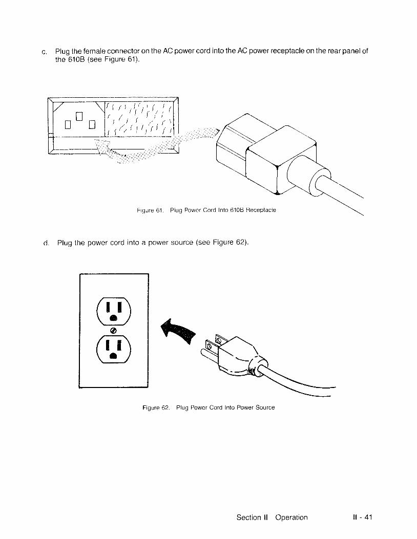
c. Plug the femaie connector on the AC power cord into the AC power receptacle on the rear panel ofthe 6108 (see Figure 61) .
' , ' , 'rt ,"', ' ",r \ / r t l r i
' t i 'i t l ' ,
Figure 61 . Plug Power Cord Into 6108 Receptacle
Plug the power cord into a power source (see Figure 62).
Figure 62. Plug Power Cord Into Power Source
Section l l Operation i l - 4 1

e. To perform a routine operation in the AMPLIFIER mode, given a random gain of 100 VA/, set thecontrols as follows (see Figure 63):'l234567B
Mode:Offset polarity:Range:Offset command:Compliance l imit:Compliance select:DPM monitor:Meter ranoe:
V-r0 - 1 KV (gain is 100 V/V)100 v50ItvoltageO - 1 K V
Figure 63. Example of Front Panel Settings
n - 4 2 6108 Cor-a-trol

POWER
f. On the front panei, t i in tne POiATEFI *witch lo elN is*:e r: igure 54!
Wait thirty seconds after the POWF:Fi switclr l iar- i har.;tr i ; ; i iu ON. the n t! iprthe l- lV switch to ON (seeFigure 65). The DPM cii l ;piays the maErritude r",f , , ' r ; i la$e belween F.l\ i CtJT and ground"
Figure 65. llV Sr,",,itch to 0N
Section l l Operation i l - 4 3
NOTE
lf the load condit ion is such that you are at-tempting to draw more current from the 6108than that set by the l imit, then the output volt-age is restricted.
EXAMPLE
With a set-Ltp of the current l imit set at the maximum 2000 pA and the supply voltage set at S00 V
For a resist ive load of 300 ki lohms:
1667 pA f lows through the load
- + I = t 6 6 7 l A
3OO Ka
With the same set-up
For a 200 ki lohms load:
- - + f = 2 5 O O l A
2OO Ka-
The current is l imited by the compliance function set to a
Therefore the voltage at the HV OUT terminal is restricted
maximum of 2000 pA.
to 400 V while 2000 pA is supplied.
I = IR
= #; 1667 pA
= ffi=Z5oo'{Ar = *
I = 2 O O O T A
2OO KJr
l l - 4 4 6108 Cor-a-trol
V= IR : (?OOOtrA)2OO K. l r = 4OO V
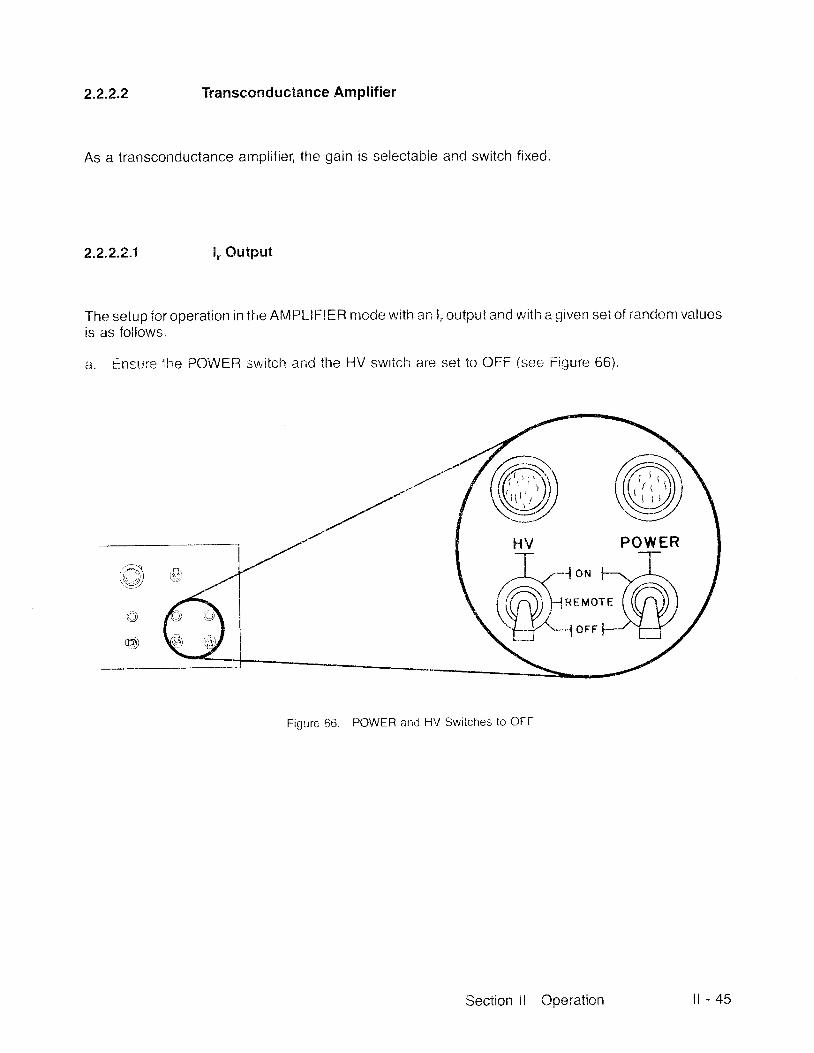
2.2.2.2 Transconductance Arnpli f ier
As a transconductance amplif ier, the gain is selectable and switch f ixed.
2.2"2.2"1 l , .Outpnt
The setup for operation in t lre Afr/ lPLlFlER mode with an l, outpui and wil lr a given set of randont valuesis as fol lows.
a. f insurs lhe POWER switch and the HV switch are set to OFF (see Figurer 66)"
Figure 66. POWER arrd HV Switches to OFF
P O W E RT
/)\/-1oN F-
i ( n ) l H R E M o T F -
Section ll Orleration i l - 4 5
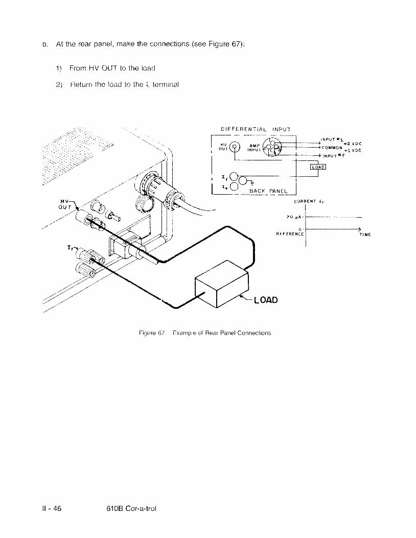
b. At the rear panel, rnake the connections (see Figure 67):
f:rorn HV OUT to the lcari
t leturn the lo;:d to the l, terminai
1 )
2 \
D I F F F . R E N T I A L I N P U T
LOAD
Figure 67. Example of Rear Panel Connections
C U R R E T I T I T
,O rO l-I*...*.n3,
|----
---'#',,,,
__i:,U
./r/'
-.r--.a' "ra'./".t'
'////'
HV1 . /o'-t-4^,
[-; ---lG;:]-
) ' |NPur *"'. uo.
I J 'r"( ' ! j ' i f , i 'k?ff i - i 'o 'uon *ruo., | \Efr---{---------J t*puT*?| ------J--;rl-I t l r -oao l, , ( - l - : l -I ',Orr----1L::-q:;* "irqlj
i l - 4 6 6108 Cor-a-trol
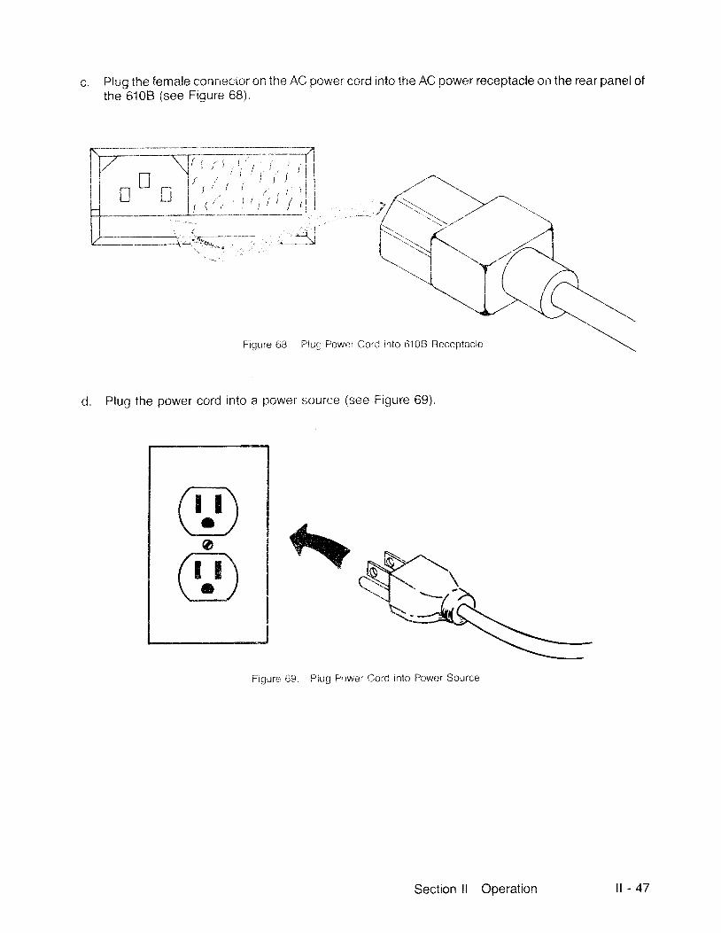
Piug the female connector c'n the AC power cord into the AC power receptacle on the rear panel ofthe 6'108 (see Figure 68).
Figure 68 Piug Fower Cord into 6108 Receptacle
d. Plug the power cord into a power source (see Figure 69).
Figure 69. Piug Pr:wer Cord into Power Source
ri-T\\-UofI-F\\g - l
Section l l Ooeration l l - 4 7

A To perform a routine operation in the l, . AMPLIFIERcontrols (see Figure 70):
1a) Mode:1 b )2) Offset polarity.3) Range:4) Offset magnitude:5) Compl iance d ia l :
6a) DPhl monitor:6b)7) Meter range:
mode, given a random gain of 20 p"AlV, set the
It',OFF0 - 200 pA (gain is 20 pA/KV)Don't Care50 (l imit ing voltage output at HV OUT con-nector to :"5,000 V)It ,0 - 200 1L"A
I /rN) \(QJi\ \--l,/\___,-
rA\r+e))
I@ \f \
OHTIAND/OFFSFE
Figure 70. Example of Front Panel Settings
l l - 4 8 6108 Cor-a-trol
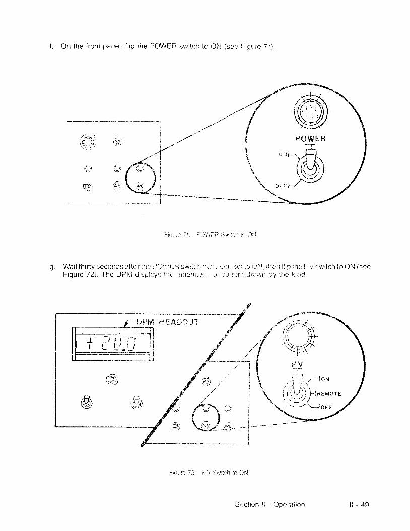
f . Cn the front panel, f i ip the FIOWEH s:witci 'r ic Old (sse f: igirre 71]
i r r ' t r r ' , ' 1 1 ; 1 , t 1 i i l j i v . r ; : h i , , - l l ' . 1
Wait thirty seconds after ther i ' i)i i i l-i-i swilc;h h.-iFigure 72). The Dlr l \ , { c l ispl i i l ts i i r r , r i tct t , i l r , -r . ,
' , . , l r r i sei l i - r f )hl i ; t r i r f i i l r the H'/ switch to ON (seerr uurterr i iJr i -rwlt hv t i re icad.
r'v=,\ / 1.(((- il,: (ti)
( Q oJ:t.rID_) (j)
'{chx*^-\"#r{".J
i-j ..'-- rox{ , ($ j , i?E, *o" 'H
,.a. .(*-"'\-' lOFF
PL /r,rlflllT
lji lcttcn ll Opcra{lr-rn i l - 4 9
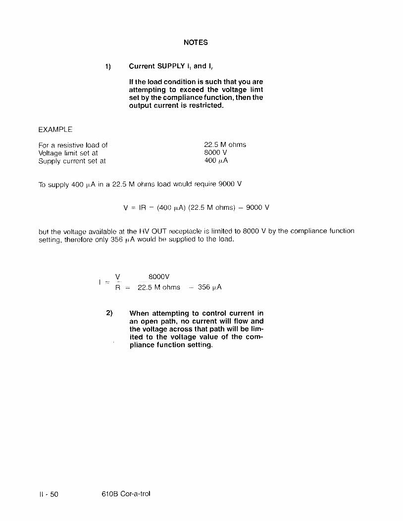
EXAMPI-E
For a resistive load ofVoltage limit set atSupply current set at
NOTES
1) Current SUPPLY l. and l,
l f the load condit ion is such that you areattempting to exceed the voltage limtset by the compliance function, then theoutput current is restricted.
22"5l \A ohms8000 v400 p,A
To supply 400 pA in a 22.5 M ofrrns load would require 9000 V
V - lR -, (400 p"A) (22.5 M ohms) : 9000 V
but the voltage available at the HV OUT receptacle is l imited to 8000 V by the compliance functionsettrng, therefore only 356 pA would be supplied to the load.
V BOOOVI
R 22.5 \A ohms 356 pA
2l When attempting to control current inan open path, no current wil l f low andthe voltage across that path wil l be l im-ited to the voltage value of the com-' pl iance function sett ing.
l l - 50 6108 Cor-a-trol

b .
2.2.2.2.2 l, Output
The setup for operation in the lt ,qh4PL if l f f i nrode and with ; l c; ivs11 set of random values is as fol lows:
a. Ensure the POWER s,,vitcl 'r and the 1""{V swrich are sei tr: OFF (see Figure 73).
i _..-.'n-."+-III
:1.--
Fiqure Tlt POWEFI an(l l lv l iv' i i tches to OF:F
At the rear panel, make the connections (see Figure Z4)
1) From HV OUT to the loerd.
2) With shield wire to l*
3) Fleturn the load to I.
I
( u R R i ! l l ,
to l
n t t r F l d a E I r r r ro r F s c l
I' c u c , n - l l - .
I_Br )c ra l ,_ -
Figurr: 74. Example ct Fear Fanel Connections
Section l l Operation i l - 5 1
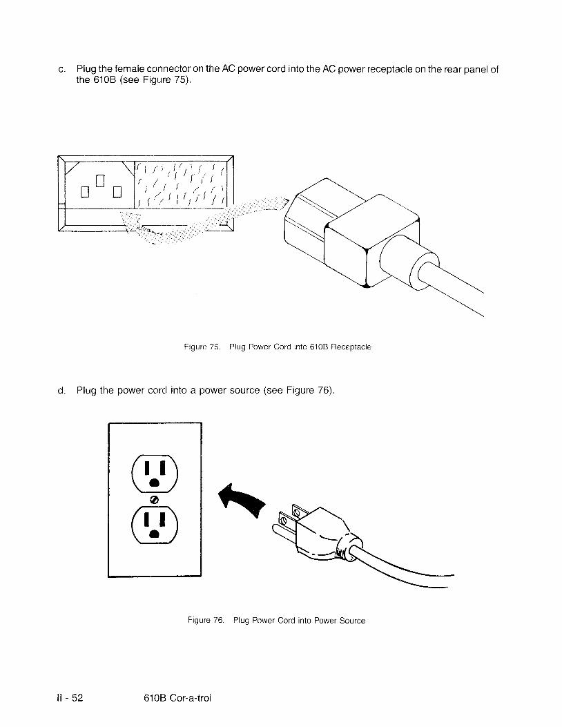
c. Plug the female connector on the AC power cord into the AC power receptacle on the rear panel ofthe 6108 (see Figure 75).
trt
,'rr: I,,, 1 ,
7 t ' / ' ,
I{
Figure 75. Plug Power Cord into 6108 Receptacle
d. Plug the power cord into a power source (see Figure 76).
Figure 76. Plug Power Cord into Power Source
atn\\_Uo[i\\-:J
l l - 5 2 610B Cor-a-trol
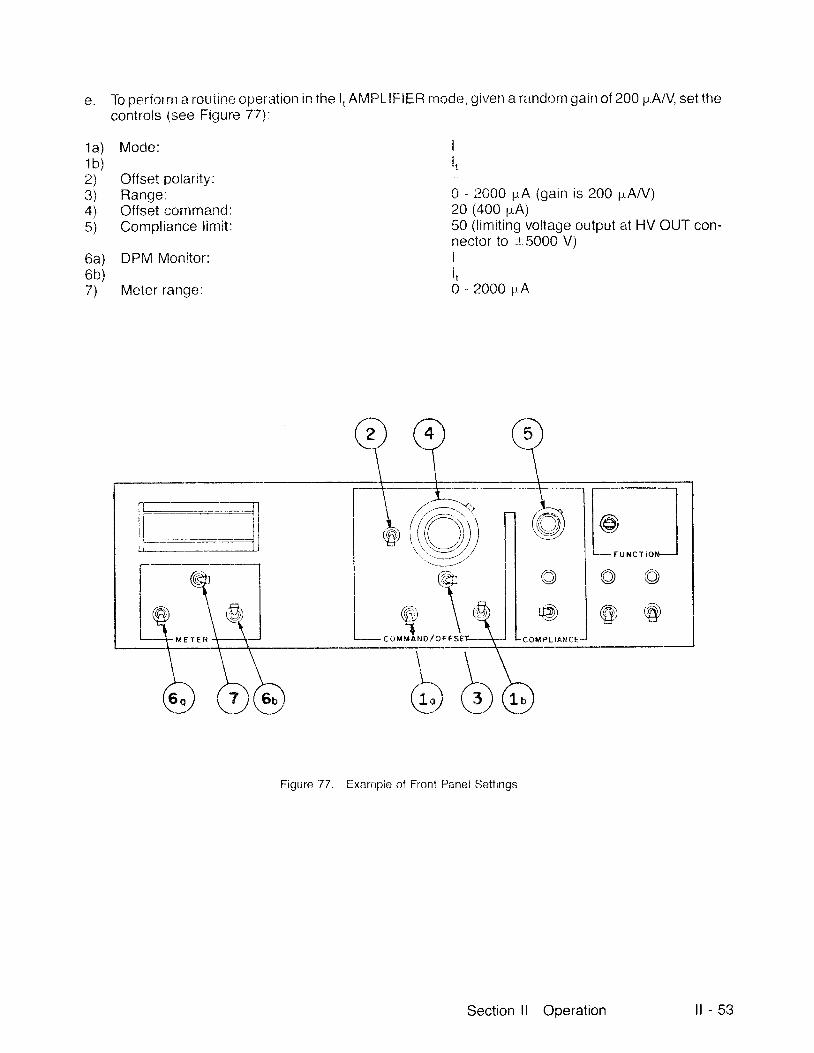
e. To perfor m a routrrre opreration in the l, AM PLIFIER rrrocle, given a randorn Eain of 200 p.A/V, set t irecontrols (see Figure 77):
1a) Mode:1 b )2) Offset polartty:3) Range:4) Offset command:5) Compl iance l imi t :
6a) DPM Monitor:6b)7) Meter ranqe:
It,
0 - 2000 pA (gain is 200 pA/V)20 (a00 pA)50 (l innit ing voltage output at HV OUT con-nector to :r5000 V)Ii t0 - 2000 pA
L iiFi\\I '.\''[ _,1,/it . - . _ ' / , t'''' '-. ',/
(.(gl1
i , {
Kii \ (tu"Jnoror.J-- COMPLIAI {CEM €T E R
Figure 77. Example of Front Panel Settings
Section l l Operation l l - 5 3

f . On the front panei, f l ip the POWER switch to ON (see Figure 78)
,',^^\{( r)fr-\t
rtpl
Fiqurr,; 78. POWF-U Switch to CIN
g Wait thirty seconds after the POWER switch has been set to ON, t l ' ien f l ip the HV s;witch to ON (seeFigure 79). The DPM clisplays the maEnitude of the current drawn by the load.
@P O W E R
@
READOUT
l l - 5 4 6108 Cor-a-trol
Figure 79 i ' lV Switch to ON
EX,AIVIPLf
For;r resist ive load ofVoltage l imit set atSupply current set at
NOTES
1) Gurrent $N"JPPLY i, anrl l ,
l f the load condit icln i$ such that you areattempting io exeeed the voltage l imitset hy the con' ipl ianee f unction, t lren theoutput current is restr ieted"
;i2 5 h"l ohnrs8000 v4 i l0 ; r "A
Tcr supply,*00 p"A irt a22.5 fil olr;':i;; I ' i i+,:-l ,.vttiit-i ri:){l{rirt} 9C00 V
V iR i. tr00 ir I \) {22.51.1 oirrns) -- 9000 V
but the voltage availah:k": at the HV OIJT relcnptacie rs l ir , . l i ted tc 8000 V by the compliance functionsett ing, therefore only 35ti 1rA woulc hc sup:tpi iet i t<r the ioatl .
V B(TJOV| .- fl 22 5 lvi cl.r'r' 'i ;i5fi uA
t) Vthen a'{tennpting tCI cCIntrol current inai l open patl" l" no current wil l f low andthe voltage acro$s that path wil l be l im-ited to the ,, ioltage value of the conn-pi iance functiq:n s*tt inq"
.$ection l l Operation l l - 55

2.2.3 Control ler Mode
In the CCNTROLLER posit ion, the 6108 is a high-voltage operational amplif ier. The amplif ier 's inputand feedback parameters are determined by the components you elect to attach to the internalterminals .
The front panelcontrols function exactly as when in the AMPLIFIER posit ion. The 610B as a control lerelement can function in a closed-loop control system (see Figure B0).
( H V r f r & I 1 )C O N T R O L
I N P U TC O N T R O L L E D
R E F E R E N C E V A R I A B L E O U T P U T
F E E D B A C K
Figure 80. 6108 as Controller in Closed-loop System
OUTPUTCONDIT ION
REFERENCECONDIT ION
V O L T A G EA T I N P U T
FEEDBACKSENSOR
i l - 5 6 6108 Cor-a-trol

2.2.3.1
The setup for operation as a
a. Ensure the PCWEH and
Control ler Element Modif ied
modif ie*d integratur with
l"iV swiiches etrc set to
a qiven set of random values is as fol lows:
OF[ : (see F igure 81) .
\,.,.)
LW)
Figure 81 POWER antl H\/ Svri lches OFF
b. l \r lake sure the power cord is discnntccted from any power source if you have connected this cord(see Figure 82) '
FigLire 82 Drscclnnect Cord frorn Power Source
n-T\\:-/ ar[il\_c_/
Section l i t)peration l l - 5 7
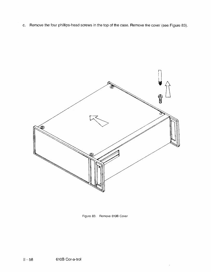
c. Remove the four phil l ips-head screws in the top of the case. Remove the cover (see Figure 83).
nU A/ \
e L _ jE
Figure 83. Remove 6108 Cover
l t - 5 8 6108 Cor-a-trol
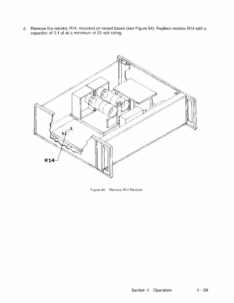
d. Remove the resistor, R14, mountecJ on raised bases (see Figure 84). Replace resistor R14 with acapacitor clf 0.1 uf at a minimurn of 25 volt rat ing.
.'t".a2'
r/t'
,/t <..a/
R14
,i.
.//);s
Figure 84. Remove ll14 Resistor
Section l l Operation i l - 5 9

e. Replace the 6108 cover and the four screws (see Figure 85):
-tt
Figure 85. Replace Cover and Screws
f At the rear panel, make the connections (see Figure 86):
1) From HV OUT to the load.2\ Return the load to ground (green receptacle).
LOAD
Figure 86. Example o{ Rear Panel Connections
6108 Cor-a-trol
u
Y+- 2 O O O A A
L I M I T
T R A N S F E R F U N C T I O N
i l - 6 0

g. Plug the fernalc {:c4n*rrtji ,:ir tl-rc .4{J pow*r ci.rrd inti: the A"C power receptacle on the rear panei ofihe i i iCB (se* [ : tgure S7) .
Plug the power cord into i i ro, l ieN'r ,{}r . r ic i , r (ssi .r Fiqure 88)
Frri l re 88. fr i , .rr l Powgr Ocrd into Power Source
r 1..;...
i.:-.? . .t - .i ' .
f; r'it\*-*9-,t'0
fn TtL9_.,',
Section l l Oneration l l - 6 1
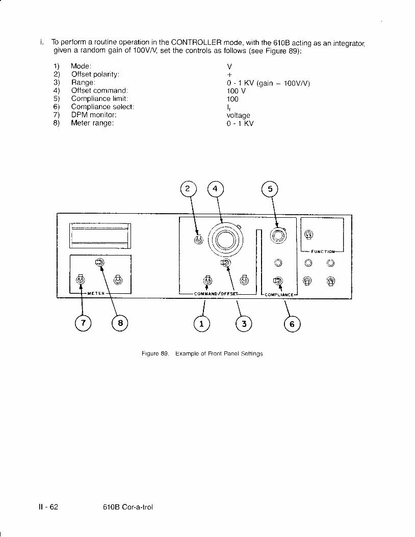
To perform a routine operation in the CONTROLLER mode, with the 6108 acting as an integrato6given a random gain of 100V/V set the controls as fol lows (see Figure Bg):
1 ) Mode :2) Offset polarity:3) Range:4) Offset command:5) Compl iance l imi t :6) Compliance select:7) DPM monitor:8) Meter range:
V+0 - 1 K V ( g a i n : 1 0 0 V 4 / )100 v100ItvoltageO . 1 K V
l oU N C T
HIin\v-//\ \ - / ,\ -\__,/,/
M E T E R
Figure 89. Example of Front Panel Settings
i l - 6 2 610B Cor-a-trol

@P O W E Rp
j On the front panel, f l ip the POWER switch to ON (see Figure 90).
[: iqLire 90. POWER Switch to ON
k. Wait thirty seconds after the POWER switch l ' ras been set to Ol'J, then f l ip the HV switch to ON (seeFiEure 91). The DPM displays the magnitude of voltage between HV OUT and ground.
Figure 91 . HV Switch to ON
ffi,fr.-,""@*::',
\ - N O T E : D P M R E A D O U T D E P E N D E N T U P O N L O A D A T I M E
: t' - l
l l - .xxxxl l /t- l
Sectron ll Operation i l - 6 3
NOTE
lf the load condition is such that you are at-tempting to draw more current from the 6108than that set by the l imit, then the output volt-age is restricted.
EXAMPLE
With a set-up of the current l imit set at the maximum 2000 pA and the supply voltage set at 500 V
For a resist ive load of 300 ki lohms:
1667 pA f lows through the load
- ? J = 1 5 6 7 1 A
With the same set-up
For a 200 ki lohms load:
3OO Kyu
- ' > f = 2 5 O O l A
ffi; 1667 AA
= ffi:25oonA
I o I =R
r = *2OO Ka-
The current is l imited by the compliance function set to a maximum of 2000 pA.
Therefore the voltage at the HV OUT terminal is restr icted to 400 V while 2000 pA is supplied.
-+ I= 2OOOrrA
2 0 0 K n
i l - 6 4 610B Cor-a-trol
V= IR = ( aOOOIA) 2OO KJ t = 4OO V
2.3 HOUSEKEEPING
The 610B is designed to keep frequent maintenance requirements to a minimum.
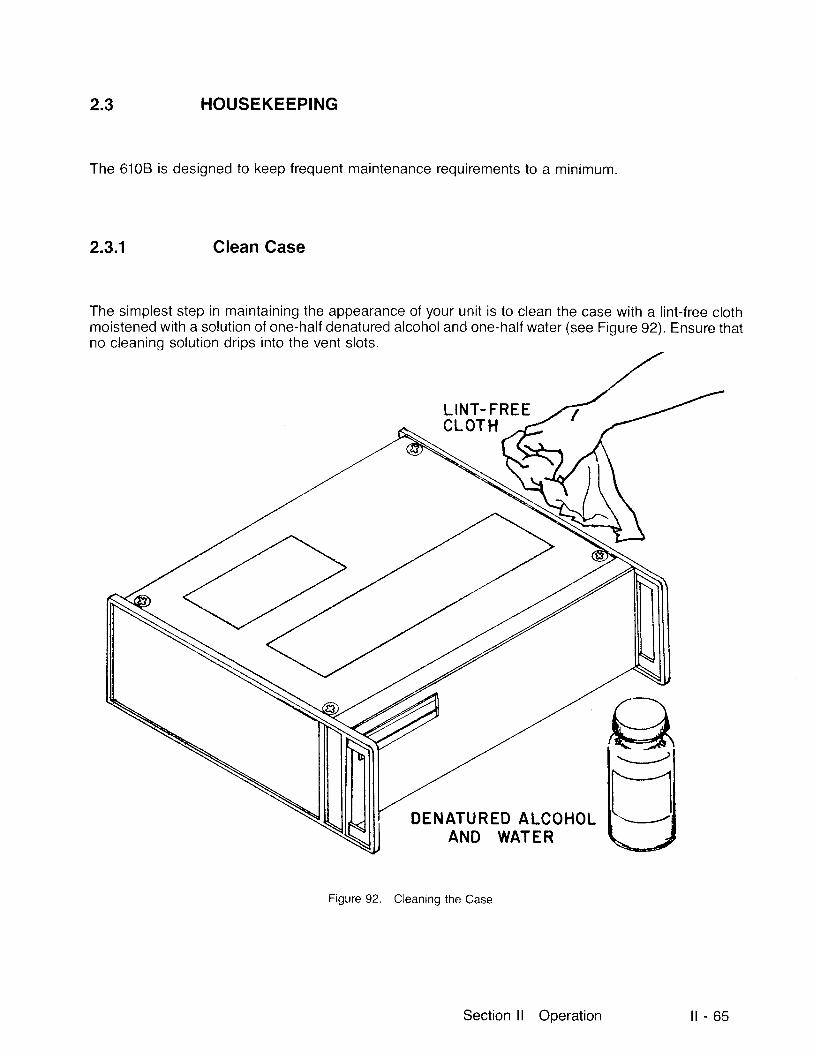
2.3.1 Clean Case
The simplest step in maintaining the appearance of your unit is to clean the case with a l int-free clothmoistened with a solution of one-half denatured alcohol and one-half water (see Figure 92). Ensure thatno cleaning solution drips into the vent slots.
L INT. FREECLOT H
DENATURED ALCOHOLAND WATER
Figure 92 Cleaning the Case
gU
Section ll Operation i l - 6 5
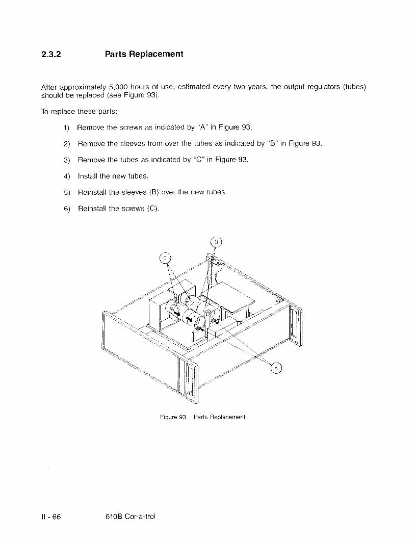
2.3.2 Parts Replacement
After approximately 5,000 hours of use, estimated every two years, the output regulators (tubes)should be replaced (see Figure 93).
To replace these parts:
1) Rernove the screws as indicated by "A" in Figure 93.
2) Remove the sleeves from over the tubes as indicated by "8" in Figure 93.
3) Remove the tubes as indicated by "C" in Figure 93.
4) Instal l the new tubes.
5) Fleinstal l the sleeves (B) over the new tubes.
6) Reinstal l the screws (C).
Figure 93. Parts Replacement
-ry
l t - 6 6 6108 Cor-a-trol

SECTION III THEORY OF OPERATION
3 DESCRIPTION
The 610B Cor-a-trol is a bipolar, four-quadrant, high-speed, high-voltage, operational amplif ier system.The 610B is self-contained (see Figure 94). l t is a versati le, analog inslrunrent. You have precisioncontrol of voltage and current at i ts output terminals.
To operate the 6108 you need only a standard AC power source. The internalvoltage supplies are thehigh-frequency, low stored energy type that reduces the potential shock hazard to users. The use ofovervoltage protection on the inputs and ultrafast output current l imit virtual ly el iminates the possibi l i tyof damage from input overvoltage and output short circuit condit ions.
WARNINGThis equipment is capable of generating volt-ages as high as 12,000 V. This voltage is gen-erated using high-frequency supplies to l imitthe available energy. Use caution in handlinqthe output of the 6108 to avoid injury.
Section l l l Theory of Operation l l l - 1
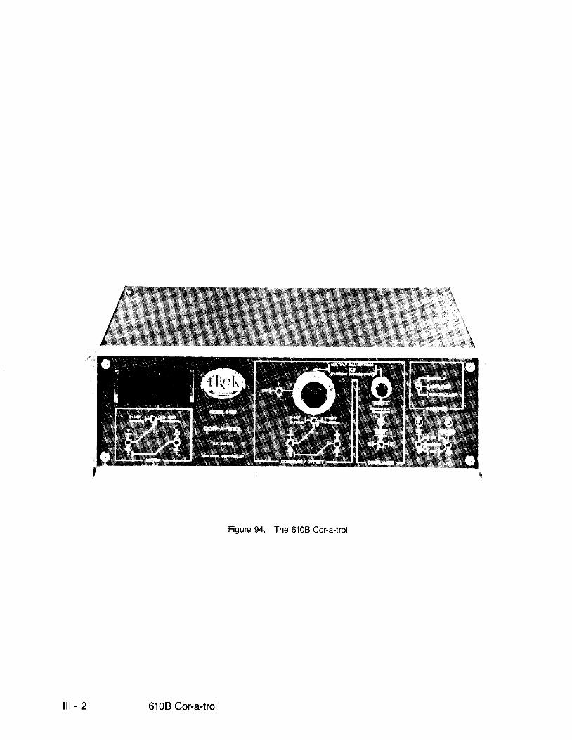
Figure 94. The 6108 Cor-a{rol
| t - 2 610B Cor-a-trol
3.1 THEORY OF OPERATION
The 6108 Cor-a- t ro lcan operate in three d i f ferent modes:SUPPLY AMPLIFIER and CONTROLLER.In al l modes, transconductance operation can be either from total output current, measured at the HVOUT terminal, 1,, or from the current return terminal, 1,. l f regulation of a single current path is desired inthe presence of mult iple loads on the output of the unit, then the abil i ty to regulate the l,- is useful. The I,terminal permits termination of an unmonitored current path in the I, mode.
3.1.1 Supply
When the 6108 Cor-a-trol is used as a supply, the input to the amplif ier is connected to an adjustable,precision voltage reference that al lows you to control and maintain the amplif ier 's output voltage orcurrent. The choice of output voltage or current is switch selectable.
3"1.2 Ampli f ier
In the amplif ier mode, the output (current or voltage) is selectable. You can select a f ixed voltage gain ora f ixed transconductance gain. The input conf iguration may be either single-ended, normal or inverted,+ or , or differential with good common mode rejection.
3.1.3 Control ler
In the control ler mode the input configuration is maintained just as in the amplif ier mode but theamplif iers input and feedback parameters are uncommitted. The adjustable reference is connected topermit setting of the output (voltage or current) at a pedistal or reference level.
Section l l l Theory of Operation i l t - 3
SECTION IV SPECIFICATIONS
4 SPECIFICATIONS
The 610B operates in three mocles: Supply, Amplif ier, and Control ler.
4.1 GENERAL INFORMATION
Digital Display
31/z digit DC voltmeter0.1"/" t l digit accuracy selectable to monitor output voltage or output current.
Controls
Power and high voltage ON/OFF on front panel"
HV remotely by EXI CONTROL connector on back panel
Section lV Specif ications lV - 1
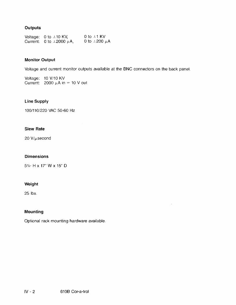
Outputs
Voltage: 0 to :r10 KV 0 to -+1 KVCurrent: 0 to :t2000 pA, 0 to t200 pA
Monitor Output
Voltage and current monitor outputs available at the BNC connectors on the back panel.
Voltage: 10 Vn0 KVCurrent: 2000 r"eA in : 10 V out
L ine Supply
100fi101220 VAC 50-60 Hz
Slew Rate
20 V/psecond
Dimensions
5 1 l q H x 1 7 " W x 1 5 " D
Weight
25 lbs.
Mounting
Optional rack mounting hardware available.
lV-2 6108Cor -a- t ro l

4.2 VOLTAGE SUPPLY
Resolution
Output voltage adjustable by ten-turn, 1,000 division potentiometer;
Each division equals 10 V for 10 KV range.Each division equals 1 V or 1 KV range.
Ranges
0 to ::10,000 V at - '-2000 pA maximum0 to +-1,000 V at :12000 pA maximum
Regulation
l ine: >.01 percent for a l ine change from .105V to 125 V.load: >.01 percent for a load change from 1 pA to 1,000 pA.
Stabil i ty
temperature: better than .01 percent/"C.time: better than .01 percent/day.
Noise and Ripple
.:0.7 V RMS +.001 percent per mA of load current.
Settl ing Time
<1.0 microsecond to 0.1 percent for a step change of 10 KV.
Slew Rate
Better than 20 V/psec.
Section lV Specifications lV - 3

4.3 CURRENT SUPPLY
Resolution
Output current adjustable by ten-turn, 1,000 division potentionneter:
each division .. 0.2 p,A on 200 pA range.,. 2.0 pA on 2,000 pA range
RanEes
0 to ,t2,000 pA at r:10 KV (maximum) covered in two ranges:
0 pA to t 200 p"A0 pA to t2,000 pA
Regulation
l ine: >.01 percent for a l ine change f rom 105 V to 125 V.load: , ' .01 percent for a load change from 10 V to 10,000 V.
Stabil i ty
temperature: better than .01 percent/.C.t ime: better than .01 percent/day.
Noise and Ripple
l, mode: -.<17 p"A RMS +.001 percent for each 10 KV change.
l, mode: -,.17 pA RMS r.001 percent for each 10 KV change.
Settl ing Time
l,. mode: .:1.0 ms to 0.1 percent for a 1,000 pA step change.
l, mode: <20 ms to 0.'1 percent for a 1,000 pA step change.
lV -4 6108Cor -a - t ro l

4.4 AMPLIFIER AND CONTROLLER
Input Offset
voltage: t2.0 V at the output.current: t50 oA rnaximum.
Input Bias Current
-* 100 pA maximum.
Input Voltage Range
t14 V max imum.
Voltage Gain
output to input: 1,000 V/V or 100 V/V (switch selectable)
Common Mode Rejection Ratio
60 dB at 60 Hz
Offset Voltage Temperature Coefficient
ambient temperature: 0'C to 50"C -- 6 mV per degree C
Offset Current Temperature Coefficient
ambient temperature: 0'C to 50'C : .02 mA per degree C
Output Swing
vol tage: *12 KV maximum.current: -+2,000 pA maximum.
Noise and Ripple
<0.7 V RMS +.001 oercent mA of load current.
Section lV Specifications lV - 5
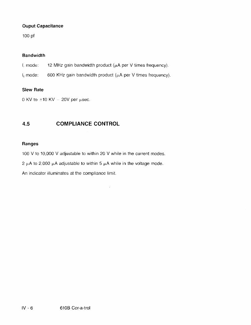
Ouput Capacitance
100 pf
Bandwidth
l, mode: 12 MHz gain bandwidth product (pA per V t imes frequency).
l , mode: 600 KHz gain bandwidth product (pA per V t imes frequency).
Slew Rate
0 KV to +10 KV : 20V per psec.
4.5 COMPLIANCE CONTROL
Ranges
100 V to 10,000 V adjustable to within 20 V while in the current modes.
2 pA to 2,000 pA adjustable to within 5 pA while in the voltage mode.
An indicator i l luminates at the compliance l imit.
lV -6 6108Cor -a- t ro l