model based hierarchical and distributed control of discrete event robotic systems using extended...
TRANSCRIPT

Genrsquoichi Yasuda
International Journal of Robotics and Automation (IJRA) Volume (2) Issue (1) 2011 27
Model Based Hierarchical and Distributed Control of Discrete Event Robotic Systems Using Extended Petri Nets
Genrsquoichi Yasuda yasudagenichigmailcom Department of Human and Computer Intelligence Nagasaki Institute of Applied Science Nagasaki 851-0193 Japan
Abstract
This paper presents a method of model based hierarchical and distributed control for discrete event robotic systems Based on the hierarchical approach the Petri net is translated into the detailed Petri net from the highest conceptual level to the lowest local control level A coordination algorithm through communication between the coordinator and the local controllers is specified and the overall distributed control system is implemented using multithread programming By the proposed method modeling simulation and control of large and complex robotic systems can be performed consistently using extended Petri nets Keywords Robotic Systems Model Based Design Distributed Control Petri Nets Implementation
1 INTRODUCTION Large and complex robotic systems such as flexible manufacturing systems are commonly decomposed into a hierarchy of abstraction levels planning scheduling coordination and local control Each level operates on a certain time horizon The planning level determines at which time each product will be introduced in the system The scheduling level produces a sequence of times for the execution of each operation on each machine or a total ordering of all the operations The coordination level updates the state representation of the system in real time supervises it and makes real-time decisions The local control level implements the real-time control of machines and devices etc interacting directly with the sensors and actuators All the emergency procedures are implemented at this level so real-time constraints may be very hard At each level any modeling has to be based on the concepts of discrete events and states where an event corresponds to a state change [1] A manufacturing cell is an elementary manufacturing system consisting of some flexible machines (machine tools assembly devices or any complex devices dedicated to complex manufacturing operations) some local storage facilities for tools and parts and some handling devices such as robots in order to transfer parts and tools Elementary manufacturing cells are called workstations At the local control level of manufacturing cells many different kinds of machines can be controlled and specific languages for different application domains are provided for example block diagrams for continuous process control and special purpose languages for CNC or robot programming For common sequential control of such machines special purpose real-time computers named Programmable Logic Controllers (PLCs) are used PLCs are replacements for relays but they incorporate many additional and complex functions such as supervisory and alarm functions and start-up and shut-down operations approaching the functionalities of general purpose process computers The most frequent programming languages are based on ladder or logic diagrams and boolean algebra However when the local control is of greater complexity the above kinds of languages may not be well adapted The development of industrial techniques makes sequential control for manufacturing cells more large and complicated one in which some subsystems operate concurrently and cooperatively Conventional representation methods based on flowcharts time diagrams state machine diagrams etc can not be used for such systems [2]
Genrsquoichi Yasuda
International Journal of Robotics and Automation (IJRA) Volume (2) Issue (1) 2011 28
To realize control systems for complex robotic systems such as flexible manufacturing cells it is necessary to provide effective tools for describing process specifications and developing control algorithms in a clear and consistent manner In the area of real-time control of discrete event systems the main problems that the system designer has to deal with are concurrency synchronization and resource sharing problems For this class of problems Petri nets have intrinsic favorable qualities and it is very easy to model sequences choices between alternatives rendez-vous and concurrent activities by means of Petri nets [2] When using Petri nets events are associated with transitions Activities are associated to the firing of transitions and to the marking of places which represents the state of the system The network model can describe the execution order of sequential and parallel tasks directly without ambiguity Moreover the formalism allowing a validation of the main properties of the Petri net control structure (liveness boundedness etc) guarantees that the control system will not fall immediately in a deadlocked situation In the field of flexible manufacturing cells the last aspect is essential because the sequences of control are complex and change very often [34] In addition to its graphic representation differentiating events and states Petri nets allows the modeling of true parallelism and the possibility of progressive modeling by using stepwise refinements or modular composition Libraries of well-tested subnets allow components reusability leading to significant reductions in the modeling effort The possibility of progressive modeling is absolutely necessary for large and complex systems because the refinement mechanism allows the building of hierarchically structured net models Furthermore a real-time implementation of the Petri net specification by software called a token player can avoid implementation errors because the specification is directly executed by the token player and the implementation of these control sequences preserves the properties of the model In this approach the Petri net model is stored in a database and the token player updates the state of the database according to the operation rules of the model For control purposes this solution is very well suited to the need of flexibility because when the control sequences change only the database needs to be changed Some techniques derived from Petri nets have been successfully introduced as an effective tool for describing control specifications and realizing the control in a uniform manner However in the field of flexible manufacturing cells the network model becomes complicated and it lacks of readability and comprehensibility [5] Therefore the flexibility and expandability are not satisfactory in order to deal with the specification change of the control system Despite the advantages offered by Petri nets the synthesis correction updating etc of the system model and programming of the controllers are not simple tasks The author proposes a Petri net based specification and real-time control method for large and complex robotic systems Based on the hierarchical and distributed structure of the system the specification procedure is a top-down approach from the conceptual level to the detailed level such that the macro representation of the system is broken down to generate the detailed Petri nets at the local machine control level Then the Petri nets are decomposed and assigned to the machine controllers to perform distributed control using Petri net based multitask processing An algorithm is proposed for coordination of machine controllers such that the behavior of the distributed control system is the same as that of the original system By the proposed method modeling simulation and control of large and complex robotic systems can be performed consistently using Petri nets
2 DISCRETE EVENT SYSTEM MODELING USING EXTENDED PETRI NETS From the viewpoint of discrete event process control an overall robotic system can be viewed as a set of distinct events and conditions mutually interrelated in a complex form An event is the start or end of an activity of a process executed by a subsystem A condition is a state in the process such as operation mode Considering the nature of discrete event systems which are characterized by the occurrence of events and changing conditions the condition-event net based specification method has been investigated The Petri net is one of the effective means to represent condition-event systems The specification method is a graphical model used as a tool to identify types of events conditions and their mutual interrelation
Genrsquoichi Yasuda
International Journal of Robotics and Automation (IJRA) Volume (2) Issue (1) 2011 29
In the condition-event systems bumping occurs when despite the holding of a condition the preceding event occurs This can result in the multiple holding of that condition and the Petri net is said to be unsafe When we consider not only the modeling but also the actual well-designed control of robotic systems the guarantee of safeness and the capability to represent input and output signals from and to the machines are required Thus the fundamental Petri net which is called the PlaceTransition net should be modified and extended in order to represent the activity contents and control strategies for the system control in detail The extended Petri net consists of the following six elements (1) Place (2) Transition (3) Directed arc (4) Token (5) Gate arc (6) Output signal arc [6] A place represents a condition of a system element or action A transition represents an event of the system A directed arc connects a place to a transition and vice versa and its direction shows the input and output relation between them thus places and transitions are alternately connected using directed arcs A token is placed in a place to indicate that the condition corresponding to the place is holding A gate arc connects a transition with a signal source and it either permits or inhibits the occurrence of the event which corresponds to the connected transition Gate arcs are classified as permissive or inhibitive and internal or external An output signal arc sends the signal from a place to an external machine The axioms for the extended Petri net execution are as follows A transition is firable or enabled if and only if it satisfies all the following firability conditions
(1) It does not have any output place filled with a token (2) It does not have any empty input place (3) It does not have any internal permissive arc signaling 0 (4) It does not have any internal inhibitive arc signaling 1
IAn enabled transition fires when it does not have any external permissive arc signaling 0 nor any external inhibitive arc signaling 1 It is considered that the time required for firing is infinitely small The firing of a transition removes a token from each input place and put a token in each output place connected to the transition In any initial marking there must not exist more than one token in a place According to these rules the number of tokens in a place never exceeds one thus the Petri net is essentially a safe graph the system is free from the bumping phenomenon The assignment of tokens into the places of a Petri net is called marking and it represents the system state The behavior of discrete event systems can be described in terms of system states and their changes In order to simulate the dynamic behavior of a system a state or marking in a Petri net is changed according to the transition firability conditions Figure 1 shows the place and gate variables used to decide the firing of a transition
FIGURE 1 Place and gate variables associated with transition firing
Formally the firability condition and external gate condition of a transition j are defined using the
logical variables in Figure 1 as follows
jt
M
N
Q R
U V
Input places
Output places
Internal gates
External gates
permissive inhibitive
∙ ∙ ∙ ∙ ∙ ∙ ∙ ∙ ∙
∙ ∙ ∙ ∙ ∙ ∙ ∙ ∙ ∙
Genrsquoichi Yasuda
International Journal of Robotics and Automation (IJRA) Volume (2) Issue (1) 2011 30
IIIIR
r
II
rj
Q
q
IP
qj
N
n
O
nj
M
m
I
mjjkgkgkpkpkt
1
1
1
1
)()()()()(
====
andandand= (1)
IIV
v
EI
vj
U
u
EP
uj
E
j kgkgkg1
1
)()()(==
and= (2)
where
M set of input places of transition j
)( kp I
mj state of input place m of transition j at time sequence k
N set of output places of transition j
)( kpO
nj state of output place n of transition j at time sequence k
Q set of internal permissive gate signals of transition j
)( kg IP
qj internal permissive gate signal variable q of transition j at time sequence k
R set of internal inhibitive gate signals of transition j
)( kg II
rj internal inhibitive gate signal variable r of transition j at time sequence k
U set of external permissive gate signals of transition j
)( kg EP
uj external permissive gate signal variable u of transition j at time sequence k
V set of external inhibitive gate signals of transition j
)( kg EI
vj external inhibitive gate signal variable v of transition j at time sequence k
The state (marking) change that is the addition or removal of a token of an input place and an output place is defined as follows
))()(()()1( kgktkpkpE
jj
I
mj
I
mj andand=+ (3)
))()(()()1( kgktkpkp E
jj
O
nj
O
nj andor=+ (4)
or
))()(()1( kgktRSTkp E
jj
I
mj and=+ (3rsquo)
))()(()1( kgktSETkp E
jj
O
nj and=+ (4rsquo)
where )(xRSTy = or )(xSET denotes that if 1=x then 0=y (reset) or 1=y (set)
respectively
Figure 2 shows Petri net representations of an elementary machine control process with machine activity For the extended Petri net it is proved that with the reversion of the existence of token in a place as well as the directions of input and output arcs of the place the firability condition of the transitions of the net is not changed So two Petri net representations in Figure 2(a) and (b) are equivalent The token in the place ldquoMachinerdquo indicates that the machine is free (Figure 2(a)) or the machine is operating (Figure 2(b)) Furthermore Figure 2(c) shows a hierarchical representation of a task the place ldquoMachine task Ardquo is the macro representation of the detailed representation composed of the subtasks 1 and 2 A task executed by a robot or an intelligent machine tool can be seen as some connection of more detailed subtasks For example transferring an object from a start position to a goal position is a sequence of the following subtasks moving the hand to the start position grasping the object moving to the goal position and putting it on the specified place
Genrsquoichi Yasuda
International Journal of Robotics and Automation (IJRA) Volume (2) Issue (1) 2011 31
Machine
subtask 1 subtask 2
Machine
subtask 1 subtask 2 Machine task A
(a) (b) (c)
FIGURE 2 Petri net representation of elementary process with machine activity (a) with loop net (b) with source and sink transitions (c) macro representation of robotic task
For the actual machine control output signal arcs are connected from associated places to the machine and external gate arcs are connected from the machine to the transitions to coordinate the succeeding subtasks as shown in Figure 3 When a token enters a place that represents a subtask the machine defined by the machine code is informed to execute a subtask with some control data that are defined as the place parameters
Machine
subtask 2 subtask 3 subtask 4 subtask 5 subtask 1
External machine
FIGURE 3 Petri net representation of manufacturing process control with output arcs and external gates
Two important system controls in discrete event robotic systems are (a) parallel control and (b) selective control Figure 4 shows the Petri net representation of parallel control In Figure 4 the parallel activities begin at the firing of transition t1 and end with transition t4 Transitions t2 and t3 are said to be concurrent if they are causally independent The subclass of Petri nets where each place has exactly one incoming arc and exactly one outgoing arc is known as marked graphs
FIGURE 4 Petri net representation of parallel control of robotic task
The subclass of Petri nets where each transition has exactly one incoming arc and exactly one outgoing arc is known as state machines Any finite state machine and its state diagram can be modeled with a state machine The structure of the place having two or more output transitions is referred to as a conflict State machines allow the representation of conflicts decisions or choices but not the synchronization of parallel activities When two or more transitions are firable only one transition should fire using gate arcs or some arbitration rule such as logical priority or specified order Figure 5 shows an example Petri net with corresponding arbiters
t1 t2
t3
t4
Genrsquoichi Yasuda
International Journal of Robotics and Automation (IJRA) Volume (2) Issue (1) 2011 32
FIGURE 5 Petri net representation of selective control of robotic task with arbiters
The Petri net described in detail with the above procedures can be used as a program for the system control while features of discrete event systems such as ordering parallelism asynchronism concurrency and conflict can be concretely described through the extended Petri net The extended Petri net is a tool for the study of condition-event systems and used to model condition-event systems through its graphical representation Analysis of the net reveals important information about the structure and the dynamic behavior of the modeled condition-event system This information can then be used to evaluate the system and suggest improvements or changes A Petri net model includes control algorithms and is used to control the real robotic process by coincidence of the behavior of the real system with the Petri net model
3 MODEL BASED HIERARCHICAL AND DISTRIBUTED CONTROL A specification procedure for discrete event robotic systems based on Petri nets is as follows First the conceptual level activities of the system are defined through a Petri net model considering the task specification corresponding to the aggregate discrete event process The places which represent the subtasks indicated as the task specification are connected by arcs via transitions in the specified order corresponding to the flow of subtasks and a workpiece The places representing the existence of machines used for the subtasks are also added to connect transitions which correspond to the beginning and ending of their subtasks Then the detailed Petri nets describing the subtasks are deduced based on activity specification and required control strategies for resources such as robots and other intelligent machines At each step of detailed specification places of the Petri net are substituted by a subnet in a manner which maintains the structural properties [7] Since in the large and complex systems the controllers are geographically distributed according to their physical (hardware) structure it is natural to implement a hierarchical and distributed control system where one controller is allocated to each control layer or block For robotic systems composed of robots machine tools and conveyors an example structure of hierarchical and distributed control is composed of one station or system controller and three machine or local controllers as shown in Figure 6 although each robot may be controlled by one robot controller The detailed Petri net is decomposed into subnets which are assigned to local controllers
Arbiter (a) Arbiter (b)
(a) (b)
Genrsquoichi Yasuda
International Journal of Robotics and Automation (IJRA) Volume (2) Issue (1) 2011 33
System controller
Robot controller
MC controller
Conveyor controller
Machining Center MC
Robot R1 Conveyor CV1
Robot R2 Conveyor CV2
FIGURE 6 Example of distributed control system
In the decomposition procedure a transition may be divided and distributed into different machine controllers as shown in Figure 7 The machine controllers should be coordinated so that these transitions fire simultaneously that is the aggregate behavior of decomposed subnets should be the same as that of the original Petri net Decomposed transitions are called global transitions and other transitions are called local transitions
t1 t2
t11 t21 t12 t22 t32 t42
decomposition
t11t12 t21t22 global transition t32t42 local transition
t3 t4
(Machine 1)
Machine 2 Machine 1
(Machine 2)
FIGURE 7 Decomposition of transitions
By the Petri net model the state of the discrete event system is represented as the marking of tokens and firing of any transition brings about change to the next state So the firability condition and state (marking) change before decomposition should be the same as those after
decomposition If transition j is divided into s transitions 1j 2j sj as shown in Figure 8 the
firability condition of a transition after decomposition is described as follows
FIGURE 8 Place and gate variables after decomposition of transition
IIIIRsub
r
II
rjsub
Qsub
q
IP
qjsub
Nsub
n
O
njsub
Msub
m
I
mjsubjsub kgkgkpkpkt1
1
1
1
)()()()()(
====
andandand= (5)
M 1 Q
1 R1
N 1 U 1 V 1
U S N S
V S
M S Q
S RS
t j1 t js
∙ ∙ ∙
Genrsquoichi Yasuda
International Journal of Robotics and Automation (IJRA) Volume (2) Issue (1) 2011 34
IIVsub
v
EI
vjsub
Usub
u
EP
ujsub
E
jsub kgkgkg1
1
)()()(==
and= (6)
From Eq (1) and Eq(5)
IS
sub
jsubj ktkt1
)()(=
= (7)
From Eq (2) and Eq (6)
)()(1
kgkgS
sub
E
jsub
E
j I=
= (8)
where
S total number of subnets
Msub set of input places of transition jsub of subnet sub
)( kp I
mjsub state of input place m of transition jsub of subnet sub at time sequence k
Nsub set of output places of transition jsub of subnet sub
)( kpO
njsub state of output place n of transition jsub of subnet sub at time sequence k
Qsub set of internal permissive gate signals of transition jsub of subnet sub
Rsub set of internal inhibitive gate signals of transition jsub of subnet sub
Usub set of external permissive gate signals of transition jsub of subnet sub
Vsub set of external inhibitive gate signals of transition jsub of subnet sub
The addition or removal of a token of a place connected to a decomposed transition is described as follows
))()(()()1( kgktkpkpE
jj
I
mjsub
I
mjsub andand=+ (9)
))()(()()1( kgktkpkp E
jj
O
njsub
O
njsub andor=+ (10)
Consequently it is proved that the firability condition of the original transition is equal to AND operation of firability conditions of decomposed transitions If and only if all of the decomposed transitions are firable then the global transitions are firable To utilize the above results the coordinator program has been introduced to coordinate the decomposed subnets so that the aggregate behavior of decomposed subnets is the same as that of the original Petri net In case that a transition in conflict with other transitions is decomposed these transitions should be coordinated by the system controller If arbitrations of the transitions are performed independently in separate subnets the results may be inconsistent with the original rule of arbitration Therefore the transitions should be arbitrated together as a group On the other hand arbitration of local transitions in conflict is performed by local machine controllers In the hierarchical and distributed control system composed of one system controller and several machine controllers the conceptual Petri net model is allocated to the Petri net based controller for management of the overall system while the detailed Petri net models are allocated to the Petri net based controllers in the machine controllers The control of the overall system is achieved by coordinating these Petri net based controllers System coordination is performed through communication between the coordinator in the system controller and the Petri net based controllers in the machine controllers [8]
Genrsquoichi Yasuda
International Journal of Robotics and Automation (IJRA) Volume (2) Issue (1) 2011 35
4 IMPLEMENTATION OF CONTROL SYSTEM The example robotic system has one or two robots one machining center and two conveyors where one is for carrying in and the other one is for carrying out as shown in Figure 9 The main execution of the system is indicated as the following task specification
(1) A workpiece is carried in by the conveyor CV1 (2) The workpiece is loaded to the machining center MC by the Robot (3) The workpiece is processed by the machining center MC (4) The workpiece is unloaded to the conveyor CV2 by the Robot (5) The workpiece is carried out by the conveyor CV2
FIGURE 9 Example of robotic system (a) with one robot (b) with two robots
At the conceptual level the discrete event processes of the robotic system are represented as shown in Figure 10 for the systems with one robot and with two robots respectively In this step if necessary control conditions such as the capacity of the system between the respective subtasks must be connected to regulate the execution of the manufacturing process For the system with one robot the place ldquoRobotrdquo has two input transitions and two output transitions but these transitions are not firable at the same time because a token is in the place ldquoMCrdquo so they are not in conflict for firing The firing of only one of these transitions is permitted using external gate arcs
Next each place representing a subtask at the conceptual level is translated into a detailed subnet Figure 11 shows the detailed Petri net representations of subtasks loading processing and unloading in Figure 10 While a Petri net at the conceptual level represents a flow of task-level commands they represent sequences of motion-level operations For registered subtasks the translation procedure is automatically executed by software
(a) (b)
FIGURE 10 Petri net representation of the example cell at the conceptual level (a) with one robot (b) with two robots
Conveyor CV1
Conveyor CV2
Machining center MC
Robot R
Conveyor CV1
Conveyor CV2
Machining center MC
Robot R1 Robot R2
Carrying in Loading Processing Unloading Carrying out
Robot R1
MC
Conveyor CV1 Conveyor CV2
Robot R2
1 4 6
2 5
3
Carrying in Loading Processing Unloading Carrying out
Robot
MC
Conveyor CV1 Conveyor CV2 1
2
3 4
5
6
(a) (b)
Genrsquoichi Yasuda
International Journal of Robotics and Automation (IJRA) Volume (2) Issue (1) 2011 36
FIGURE 11 Detailed Petri net representation of subtasks
The detailed Petri net representation of the example system is shown in Figure 12 where the detailed Petri net is not decomposed and the control system is centralized For the distributed control system shown in Figure 6 the Petri net representations assigned to the machine controllers are shown in Figure 13 External permissive gate arcs from sensors for detecting the completion of work handling are employed For example for grasping action of a robot the set of touch sensors on the fingers of the robot indicates whether the robot has or has not grasped a workpiece and for moving action of a robot the set of limit switch sensors for robot arm positioning indicates whether the robot has or has not reached a target position
FIGURE 12 Detailed Petri net representation of whole system task
Waiting
Grasp Moving
Waiting
Put on Moving
(MC)
(Robot R2)
(Conveyor CV2)
Backward Positioning Machining Forward Unfixing t3 t4
(a) Loading
(b) Processing
(c) Unloading
t9
t5
t4
Forward Waiting Fixing
Grasp Moving
Waiting
Put on Moving Waiting
(Conveyor CV1)
(Robot R1)
(MC)
t2
t3
t7
t8
t1
t2 t7
t8 t3
t4
t9
t5 t6
Forwar
Waitin
Fixin
Gras
Movin
Waitin
Put on Movin
Waiting
(Convey
C
1
(Rob
1
(MC Processi
Waitin
Grasp
Movin
Waitin
Put
Movin
(MC
(Rob
2
(Convey
2
Carrying
Carrying
Genrsquoichi Yasuda
International Journal of Robotics and Automation (IJRA) Volume (2) Issue (1) 2011 37
(a) Robot controller
(b) MC controller
Carrying in Waiting
(Conveyor CV1)
Carrying out Waiting
(Conveyor CV2)
(c) Conveyor controller
FIGURE 13 Detailed Petri net representation of machine controllers with external permissive gate arcs from
sensors for work handling
( global transition local transition permissive gate arc)
For the example robotic system a hierarchical and distributed control system has been realized using a set of PCs Each machine controller is implemented on a dedicated PC The system controller is implemented on another PC Communications among the controllers are performed using serial communication interfaces (RS-485) The names of global transitions and their conflict relations are loaded into the coordinator in the system controller The connection structure of a decomposed Petri net model and conflict relations among local transitions are loaded into the Petri net based controller in a machine controller Using the names of transitions in the subsystems global transitions are defined for example G2 t0-2 t1-21 t2-22 t3-23 indicates that the global transition G2 is composed of the transition no2 of System controller (subsystem no0) the transition no21 of Robot controller the transition no22 of MC controller (subsystem no2) and the transition no23 of Conveyor controller (subsystem no3) Then the coordinator information for the example distributed control system is as follows
G1 t0-1 t3-13 start of carring in G2 t0-2 t1-21 t2-22 t3-23 start of loading from CV1 G3 t1-71 t3-73 end of grasp on CV1 G4 t1-81 t2-82 end of putting on MC G5 t0-3 t1-31 t2-32 end of loading into MC G6 t0-4 t1-41 t2-42 t3-43 start of unloading from MC G7 t1-91 t2-92 end of grasp on MC G8 t0-5 t1-51 t3-53 end of putting on CV2 G9 t0-6 t3-63 end of carring out
Grasp Moving Put on Moving Waiting
(Robot R1)
Grasp Moving Put on Moving
(Robot R2)
Fixing Waiting Forward Waiting Processing
t21 t71 t81
t31
t41 t91 t51
t22 t82 t32
t42 t92
t13 t23
t73 t43 t53
t63
Genrsquoichi Yasuda
International Journal of Robotics and Automation (IJRA) Volume (2) Issue (1) 2011 38
By executing the coordinator and Petri net based controllers algorithms based on loaded information simulation experiments have been performed The robot controller executes robot motion control through the transmission of command The MC controller and the conveyor controller communicate with a dedicated PLC The Petri net simulator initiates the execution of the subtasks attached to the fired transitions through the serial interface to the robot or other external machines When a task ends its activity it informs the simulator to proceed with the next activations by the external permissive gate arc The detailed Petri net representation for real-time external machine control is shown in Figure 14
FIGURE 14 Detailed Petri net representation of external machine control
Experimental set up of the example of robotic system presented in this paper is shown in Figure 15 Control software on each PC is written using multithreaded programming [9] Petri net simulation and task execution program through serial interface are implemented as threads in each machine controller Real-time task execution using multithreaded programming is shown in Figure 16 In a multithreaded operating system a thread is an independent flow of execution in a process and all threads share the code data heap and system memory areas of that process So all threads in a process can access all global data Further because each thread has a separate CPU state and its own stack memory all local variables and function arguments are private to a specific thread Itrsquos easy for threads to interact with each other by the way of synchronization objects and intertask communications because they have some shared memory for communication as the processrsquos global data Context switching between threads involves simply saving the CPU state for the current thread and loading the CPU state for the new thread [10] In the control system both the Petri net simulation thread and the task execution thread access to the external gate variables as shared variables the task execution thread writes and the Petri net simulation thread reads Mutual exclusive access control was implemented as shown in Figure 16 so that while one thread accesses to the shared variables the other thread can not access to them The Petri net simulator thread waits for the external gate signal using an event object and after the task execution threads write the Petri net simulator thread reads and then the associated transition fires directly Control software using multithreaded programming was written in Visual C under OS Windows XP SP3 on general PCs The Petri net modeling thread is executed as the main thread to perform the Petri net modeling drawing and modification for task specification For the example system detailed Petri net models can be automatically generated using the database of robotic operations When the transformation of graphic data of the Petri net model into internal structural data is finished the Petri net simulation thread starts Experiments using a real robot show that the Petri net simulation thread and the task execution threads proceed concurrently with even priority and the values of external gate variables are changed successfully
t1 t2
detailed representation
External machine
t1 t2
reception report
unit operation
status
reception
working
command request
Genrsquoichi Yasuda
International Journal of Robotics and Automation (IJRA) Volume (2) Issue (1) 2011 39
FIGURE 15 View of experimental set up of robotic system
FIGURE 16 Real-time execution of subtasks using multithreaded programming
Experimental results show that the decomposed transitions fire simultaneously as the original transition of the detailed Petri net of the whole system task [11] The robots cooperated with the conveyors and the machining center and the example robotic system performed the task specification successfully Firing transitions and marking of tokens can be directly observed on the display at each time sequence using the simulator on each PC [12] as shown in Figure 17 During simulation and task execution it is judged by the simulator that whether it is in a deadlocked situation or not and the user can stop the task execution through the simulator at any time
Modeling thread
Simulation thread
Task execution thread
(machine 1)
Task specification and graphic drawing of Petri net models Control parameter setting associated with transition firing
Petri net execution based on transition firability and gate variables
Real-time task execution of each machine controller by command sending and status reception through serial interface
Machine controller 1
status
External gate variables (machine 1)
read
write
《shared variables》
command reception
statusreport
Activation of simulation thread through user interface
Activation of task execution thread in case of transition firing
command
Genrsquoichi Yasuda
International Journal of Robotics and Automation (IJRA) Volume (2) Issue (1) 2011 40
FIGURE 17 View of Petri net simulator
5 CONCLUSIONS A methodology of model based design and implementation using Petri nets to construct hierarchical and distributed control systems which correspond to the hardware structure of robotic systems has been proposed By introduction of the coordinator the Petri net based controllers are arranged according to the hierarchical and distributed nature of the overall system the coordination mechanism is implemented in each layer repeatedly The Petri net model in each Petri net based machine controller is not so large and easily manageable The overall control structure of the example robotic system was implemented on general PCs using multithreaded programming In accordance with the implementation using multithreaded programming hierarchical and distributed implementation under a real-time operating system on a network of microcomputers connected via a serial bus is also possible where each microcomputer is dedicated to the local Petri net model of a subsystem in the overall robotic system Local Petri net models are so simple that they can be implemented on general PLCs Thus modeling simulation and control of large and complex manufacturing systems can be performed consistently using Petri nets
6 REFERENCES 1 M Silva ldquoPetri nets and flexible manufacturingrdquo in Advances in Petri Nets 1989 Lecture Notes
in Computer Science vol 424 G Rozenberg Ed Berlin Springer-Verlag 1990 pp 374-417
Genrsquoichi Yasuda
International Journal of Robotics and Automation (IJRA) Volume (2) Issue (1) 2011 41
2 M Silva and S Velilla ldquoProgrammable logic controllers and Petri nets A comparative studyrdquo
in IFAC Software for Computer Control 1982 G Ferrate and EA Puente Eds Oxford UK Pergamon 1982 pp 83-88
3 W Reisig Petri Nets Berlin Springer-Verlag 1985 4 T Murata N Komoda K Matsumoto and KHaruna ldquoA Petri net based controller for flexible
and maintainable sequence control and its application in factory automationrdquo IEEE Trans Industrial Electronics vol 33(1) pp 1-8 1986
5 R David and H Alla Petri Nets and Grafcet Tools for Modelling Discrete Events Systems UK
Prentice-Hall International 1992 6 K Hasegawa K Takahashi R Masuda and H Ohno ldquoProposal of Mark Flow Graph for
discrete system controlrdquo Trans of SICE vol 20(2) pp 122-129 1984 7 PE Miyagi K Hasegawa and K Takahashi ldquoA programming language for discrete event
production systems based on Production Flow Schema and Mark Flow Graphrdquo Trans of SICE vol 24(2) pp 183-190 1988
8 G Yasuda ldquoImplementation of distributed control architecture for robotic manufacturing
systems using Petri netsrdquo in Proceedings of 2006 IMACS Multiconference on Computational Engineering in Systems Applications 2006 pp 1155-1160
9 G Yasuda ldquoA distributed control and communication structure for multiple cooperating robot
agentsrdquo in IFAC Artificial Intelligence in Real Time Control 2000 Oxford UK Pergamon 2000 pp 283-288
10 R Grehan R Moote and I Cyliax Real-time Programming A Guide to 32-bit Embedded
Development Reading Massachusetts Addison-Wesley 1998 11 G Yasuda ldquoImplementation of hierarchical and distributed control for discrete event robotic
manufacturing systemsrdquo in Proceedings of the 38th International Conference on Computers and Industrial Engineering 2008 pp 2580-2589
12 G Yasuda ldquoDesign and implementation of distributed control architecture for flexible
manufacturing systems based on Petri netsrdquo in Proceedings of the 10th Asia-Pacific Industrial Engineering and Management Systems Conference 2009 pp 2525-2534

Genrsquoichi Yasuda
International Journal of Robotics and Automation (IJRA) Volume (2) Issue (1) 2011 34
IIVsub
v
EI
vjsub
Usub
u
EP
ujsub
E
jsub kgkgkg1
1
)()()(==
and= (6)
From Eq (1) and Eq(5)
IS
sub
jsubj ktkt1
)()(=
= (7)
From Eq (2) and Eq (6)
)()(1
kgkgS
sub
E
jsub
E
j I=
= (8)
where
S total number of subnets
Msub set of input places of transition jsub of subnet sub
)( kp I
mjsub state of input place m of transition jsub of subnet sub at time sequence k
Nsub set of output places of transition jsub of subnet sub
)( kpO
njsub state of output place n of transition jsub of subnet sub at time sequence k
Qsub set of internal permissive gate signals of transition jsub of subnet sub
Rsub set of internal inhibitive gate signals of transition jsub of subnet sub
Usub set of external permissive gate signals of transition jsub of subnet sub
Vsub set of external inhibitive gate signals of transition jsub of subnet sub
The addition or removal of a token of a place connected to a decomposed transition is described as follows
))()(()()1( kgktkpkpE
jj
I
mjsub
I
mjsub andand=+ (9)
))()(()()1( kgktkpkp E
jj
O
njsub
O
njsub andor=+ (10)
Consequently it is proved that the firability condition of the original transition is equal to AND operation of firability conditions of decomposed transitions If and only if all of the decomposed transitions are firable then the global transitions are firable To utilize the above results the coordinator program has been introduced to coordinate the decomposed subnets so that the aggregate behavior of decomposed subnets is the same as that of the original Petri net In case that a transition in conflict with other transitions is decomposed these transitions should be coordinated by the system controller If arbitrations of the transitions are performed independently in separate subnets the results may be inconsistent with the original rule of arbitration Therefore the transitions should be arbitrated together as a group On the other hand arbitration of local transitions in conflict is performed by local machine controllers In the hierarchical and distributed control system composed of one system controller and several machine controllers the conceptual Petri net model is allocated to the Petri net based controller for management of the overall system while the detailed Petri net models are allocated to the Petri net based controllers in the machine controllers The control of the overall system is achieved by coordinating these Petri net based controllers System coordination is performed through communication between the coordinator in the system controller and the Petri net based controllers in the machine controllers [8]
Genrsquoichi Yasuda
International Journal of Robotics and Automation (IJRA) Volume (2) Issue (1) 2011 35
4 IMPLEMENTATION OF CONTROL SYSTEM The example robotic system has one or two robots one machining center and two conveyors where one is for carrying in and the other one is for carrying out as shown in Figure 9 The main execution of the system is indicated as the following task specification
(1) A workpiece is carried in by the conveyor CV1 (2) The workpiece is loaded to the machining center MC by the Robot (3) The workpiece is processed by the machining center MC (4) The workpiece is unloaded to the conveyor CV2 by the Robot (5) The workpiece is carried out by the conveyor CV2
FIGURE 9 Example of robotic system (a) with one robot (b) with two robots
At the conceptual level the discrete event processes of the robotic system are represented as shown in Figure 10 for the systems with one robot and with two robots respectively In this step if necessary control conditions such as the capacity of the system between the respective subtasks must be connected to regulate the execution of the manufacturing process For the system with one robot the place ldquoRobotrdquo has two input transitions and two output transitions but these transitions are not firable at the same time because a token is in the place ldquoMCrdquo so they are not in conflict for firing The firing of only one of these transitions is permitted using external gate arcs
Next each place representing a subtask at the conceptual level is translated into a detailed subnet Figure 11 shows the detailed Petri net representations of subtasks loading processing and unloading in Figure 10 While a Petri net at the conceptual level represents a flow of task-level commands they represent sequences of motion-level operations For registered subtasks the translation procedure is automatically executed by software
(a) (b)
FIGURE 10 Petri net representation of the example cell at the conceptual level (a) with one robot (b) with two robots
Conveyor CV1
Conveyor CV2
Machining center MC
Robot R
Conveyor CV1
Conveyor CV2
Machining center MC
Robot R1 Robot R2
Carrying in Loading Processing Unloading Carrying out
Robot R1
MC
Conveyor CV1 Conveyor CV2
Robot R2
1 4 6
2 5
3
Carrying in Loading Processing Unloading Carrying out
Robot
MC
Conveyor CV1 Conveyor CV2 1
2
3 4
5
6
(a) (b)
Genrsquoichi Yasuda
International Journal of Robotics and Automation (IJRA) Volume (2) Issue (1) 2011 36
FIGURE 11 Detailed Petri net representation of subtasks
The detailed Petri net representation of the example system is shown in Figure 12 where the detailed Petri net is not decomposed and the control system is centralized For the distributed control system shown in Figure 6 the Petri net representations assigned to the machine controllers are shown in Figure 13 External permissive gate arcs from sensors for detecting the completion of work handling are employed For example for grasping action of a robot the set of touch sensors on the fingers of the robot indicates whether the robot has or has not grasped a workpiece and for moving action of a robot the set of limit switch sensors for robot arm positioning indicates whether the robot has or has not reached a target position
FIGURE 12 Detailed Petri net representation of whole system task
Waiting
Grasp Moving
Waiting
Put on Moving
(MC)
(Robot R2)
(Conveyor CV2)
Backward Positioning Machining Forward Unfixing t3 t4
(a) Loading
(b) Processing
(c) Unloading
t9
t5
t4
Forward Waiting Fixing
Grasp Moving
Waiting
Put on Moving Waiting
(Conveyor CV1)
(Robot R1)
(MC)
t2
t3
t7
t8
t1
t2 t7
t8 t3
t4
t9
t5 t6
Forwar
Waitin
Fixin
Gras
Movin
Waitin
Put on Movin
Waiting
(Convey
C
1
(Rob
1
(MC Processi
Waitin
Grasp
Movin
Waitin
Put
Movin
(MC
(Rob
2
(Convey
2
Carrying
Carrying
Genrsquoichi Yasuda
International Journal of Robotics and Automation (IJRA) Volume (2) Issue (1) 2011 37
(a) Robot controller
(b) MC controller
Carrying in Waiting
(Conveyor CV1)
Carrying out Waiting
(Conveyor CV2)
(c) Conveyor controller
FIGURE 13 Detailed Petri net representation of machine controllers with external permissive gate arcs from
sensors for work handling
( global transition local transition permissive gate arc)
For the example robotic system a hierarchical and distributed control system has been realized using a set of PCs Each machine controller is implemented on a dedicated PC The system controller is implemented on another PC Communications among the controllers are performed using serial communication interfaces (RS-485) The names of global transitions and their conflict relations are loaded into the coordinator in the system controller The connection structure of a decomposed Petri net model and conflict relations among local transitions are loaded into the Petri net based controller in a machine controller Using the names of transitions in the subsystems global transitions are defined for example G2 t0-2 t1-21 t2-22 t3-23 indicates that the global transition G2 is composed of the transition no2 of System controller (subsystem no0) the transition no21 of Robot controller the transition no22 of MC controller (subsystem no2) and the transition no23 of Conveyor controller (subsystem no3) Then the coordinator information for the example distributed control system is as follows
G1 t0-1 t3-13 start of carring in G2 t0-2 t1-21 t2-22 t3-23 start of loading from CV1 G3 t1-71 t3-73 end of grasp on CV1 G4 t1-81 t2-82 end of putting on MC G5 t0-3 t1-31 t2-32 end of loading into MC G6 t0-4 t1-41 t2-42 t3-43 start of unloading from MC G7 t1-91 t2-92 end of grasp on MC G8 t0-5 t1-51 t3-53 end of putting on CV2 G9 t0-6 t3-63 end of carring out
Grasp Moving Put on Moving Waiting
(Robot R1)
Grasp Moving Put on Moving
(Robot R2)
Fixing Waiting Forward Waiting Processing
t21 t71 t81
t31
t41 t91 t51
t22 t82 t32
t42 t92
t13 t23
t73 t43 t53
t63
Genrsquoichi Yasuda
International Journal of Robotics and Automation (IJRA) Volume (2) Issue (1) 2011 38
By executing the coordinator and Petri net based controllers algorithms based on loaded information simulation experiments have been performed The robot controller executes robot motion control through the transmission of command The MC controller and the conveyor controller communicate with a dedicated PLC The Petri net simulator initiates the execution of the subtasks attached to the fired transitions through the serial interface to the robot or other external machines When a task ends its activity it informs the simulator to proceed with the next activations by the external permissive gate arc The detailed Petri net representation for real-time external machine control is shown in Figure 14
FIGURE 14 Detailed Petri net representation of external machine control
Experimental set up of the example of robotic system presented in this paper is shown in Figure 15 Control software on each PC is written using multithreaded programming [9] Petri net simulation and task execution program through serial interface are implemented as threads in each machine controller Real-time task execution using multithreaded programming is shown in Figure 16 In a multithreaded operating system a thread is an independent flow of execution in a process and all threads share the code data heap and system memory areas of that process So all threads in a process can access all global data Further because each thread has a separate CPU state and its own stack memory all local variables and function arguments are private to a specific thread Itrsquos easy for threads to interact with each other by the way of synchronization objects and intertask communications because they have some shared memory for communication as the processrsquos global data Context switching between threads involves simply saving the CPU state for the current thread and loading the CPU state for the new thread [10] In the control system both the Petri net simulation thread and the task execution thread access to the external gate variables as shared variables the task execution thread writes and the Petri net simulation thread reads Mutual exclusive access control was implemented as shown in Figure 16 so that while one thread accesses to the shared variables the other thread can not access to them The Petri net simulator thread waits for the external gate signal using an event object and after the task execution threads write the Petri net simulator thread reads and then the associated transition fires directly Control software using multithreaded programming was written in Visual C under OS Windows XP SP3 on general PCs The Petri net modeling thread is executed as the main thread to perform the Petri net modeling drawing and modification for task specification For the example system detailed Petri net models can be automatically generated using the database of robotic operations When the transformation of graphic data of the Petri net model into internal structural data is finished the Petri net simulation thread starts Experiments using a real robot show that the Petri net simulation thread and the task execution threads proceed concurrently with even priority and the values of external gate variables are changed successfully
t1 t2
detailed representation
External machine
t1 t2
reception report
unit operation
status
reception
working
command request
Genrsquoichi Yasuda
International Journal of Robotics and Automation (IJRA) Volume (2) Issue (1) 2011 39
FIGURE 15 View of experimental set up of robotic system
FIGURE 16 Real-time execution of subtasks using multithreaded programming
Experimental results show that the decomposed transitions fire simultaneously as the original transition of the detailed Petri net of the whole system task [11] The robots cooperated with the conveyors and the machining center and the example robotic system performed the task specification successfully Firing transitions and marking of tokens can be directly observed on the display at each time sequence using the simulator on each PC [12] as shown in Figure 17 During simulation and task execution it is judged by the simulator that whether it is in a deadlocked situation or not and the user can stop the task execution through the simulator at any time
Modeling thread
Simulation thread
Task execution thread
(machine 1)
Task specification and graphic drawing of Petri net models Control parameter setting associated with transition firing
Petri net execution based on transition firability and gate variables
Real-time task execution of each machine controller by command sending and status reception through serial interface
Machine controller 1
status
External gate variables (machine 1)
read
write
《shared variables》
command reception
statusreport
Activation of simulation thread through user interface
Activation of task execution thread in case of transition firing
command
Genrsquoichi Yasuda
International Journal of Robotics and Automation (IJRA) Volume (2) Issue (1) 2011 40
FIGURE 17 View of Petri net simulator
5 CONCLUSIONS A methodology of model based design and implementation using Petri nets to construct hierarchical and distributed control systems which correspond to the hardware structure of robotic systems has been proposed By introduction of the coordinator the Petri net based controllers are arranged according to the hierarchical and distributed nature of the overall system the coordination mechanism is implemented in each layer repeatedly The Petri net model in each Petri net based machine controller is not so large and easily manageable The overall control structure of the example robotic system was implemented on general PCs using multithreaded programming In accordance with the implementation using multithreaded programming hierarchical and distributed implementation under a real-time operating system on a network of microcomputers connected via a serial bus is also possible where each microcomputer is dedicated to the local Petri net model of a subsystem in the overall robotic system Local Petri net models are so simple that they can be implemented on general PLCs Thus modeling simulation and control of large and complex manufacturing systems can be performed consistently using Petri nets
6 REFERENCES 1 M Silva ldquoPetri nets and flexible manufacturingrdquo in Advances in Petri Nets 1989 Lecture Notes
in Computer Science vol 424 G Rozenberg Ed Berlin Springer-Verlag 1990 pp 374-417
Genrsquoichi Yasuda
International Journal of Robotics and Automation (IJRA) Volume (2) Issue (1) 2011 41
2 M Silva and S Velilla ldquoProgrammable logic controllers and Petri nets A comparative studyrdquo
in IFAC Software for Computer Control 1982 G Ferrate and EA Puente Eds Oxford UK Pergamon 1982 pp 83-88
3 W Reisig Petri Nets Berlin Springer-Verlag 1985 4 T Murata N Komoda K Matsumoto and KHaruna ldquoA Petri net based controller for flexible
and maintainable sequence control and its application in factory automationrdquo IEEE Trans Industrial Electronics vol 33(1) pp 1-8 1986
5 R David and H Alla Petri Nets and Grafcet Tools for Modelling Discrete Events Systems UK
Prentice-Hall International 1992 6 K Hasegawa K Takahashi R Masuda and H Ohno ldquoProposal of Mark Flow Graph for
discrete system controlrdquo Trans of SICE vol 20(2) pp 122-129 1984 7 PE Miyagi K Hasegawa and K Takahashi ldquoA programming language for discrete event
production systems based on Production Flow Schema and Mark Flow Graphrdquo Trans of SICE vol 24(2) pp 183-190 1988
8 G Yasuda ldquoImplementation of distributed control architecture for robotic manufacturing
systems using Petri netsrdquo in Proceedings of 2006 IMACS Multiconference on Computational Engineering in Systems Applications 2006 pp 1155-1160
9 G Yasuda ldquoA distributed control and communication structure for multiple cooperating robot
agentsrdquo in IFAC Artificial Intelligence in Real Time Control 2000 Oxford UK Pergamon 2000 pp 283-288
10 R Grehan R Moote and I Cyliax Real-time Programming A Guide to 32-bit Embedded
Development Reading Massachusetts Addison-Wesley 1998 11 G Yasuda ldquoImplementation of hierarchical and distributed control for discrete event robotic
manufacturing systemsrdquo in Proceedings of the 38th International Conference on Computers and Industrial Engineering 2008 pp 2580-2589
12 G Yasuda ldquoDesign and implementation of distributed control architecture for flexible
manufacturing systems based on Petri netsrdquo in Proceedings of the 10th Asia-Pacific Industrial Engineering and Management Systems Conference 2009 pp 2525-2534
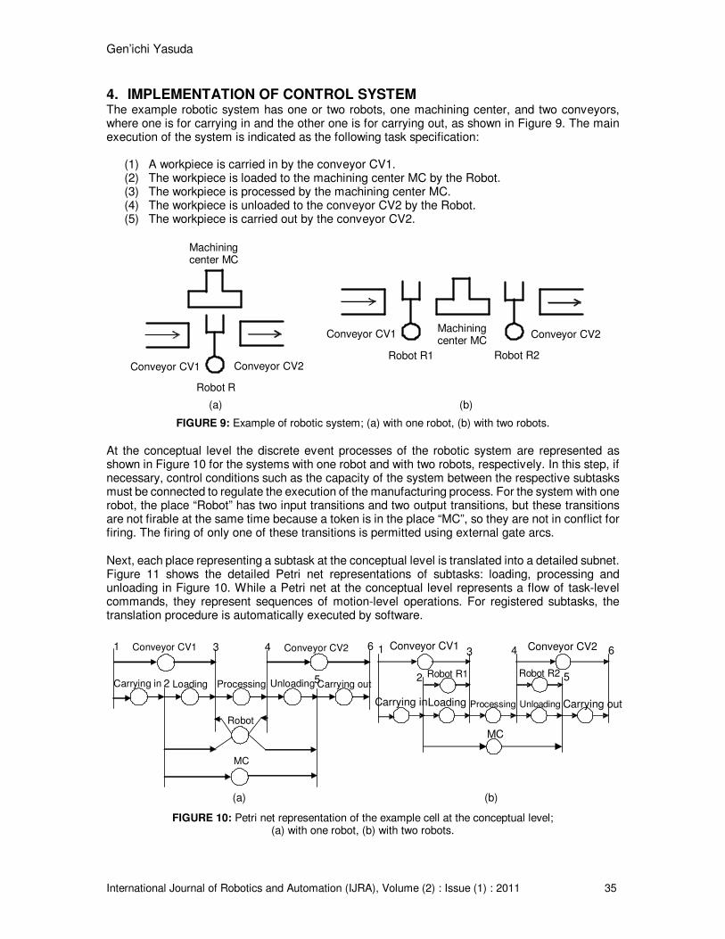
Genrsquoichi Yasuda
International Journal of Robotics and Automation (IJRA) Volume (2) Issue (1) 2011 41
2 M Silva and S Velilla ldquoProgrammable logic controllers and Petri nets A comparative studyrdquo
in IFAC Software for Computer Control 1982 G Ferrate and EA Puente Eds Oxford UK Pergamon 1982 pp 83-88
3 W Reisig Petri Nets Berlin Springer-Verlag 1985 4 T Murata N Komoda K Matsumoto and KHaruna ldquoA Petri net based controller for flexible
and maintainable sequence control and its application in factory automationrdquo IEEE Trans Industrial Electronics vol 33(1) pp 1-8 1986
5 R David and H Alla Petri Nets and Grafcet Tools for Modelling Discrete Events Systems UK
Prentice-Hall International 1992 6 K Hasegawa K Takahashi R Masuda and H Ohno ldquoProposal of Mark Flow Graph for
discrete system controlrdquo Trans of SICE vol 20(2) pp 122-129 1984 7 PE Miyagi K Hasegawa and K Takahashi ldquoA programming language for discrete event
production systems based on Production Flow Schema and Mark Flow Graphrdquo Trans of SICE vol 24(2) pp 183-190 1988
8 G Yasuda ldquoImplementation of distributed control architecture for robotic manufacturing
systems using Petri netsrdquo in Proceedings of 2006 IMACS Multiconference on Computational Engineering in Systems Applications 2006 pp 1155-1160
9 G Yasuda ldquoA distributed control and communication structure for multiple cooperating robot
agentsrdquo in IFAC Artificial Intelligence in Real Time Control 2000 Oxford UK Pergamon 2000 pp 283-288
10 R Grehan R Moote and I Cyliax Real-time Programming A Guide to 32-bit Embedded
Development Reading Massachusetts Addison-Wesley 1998 11 G Yasuda ldquoImplementation of hierarchical and distributed control for discrete event robotic
manufacturing systemsrdquo in Proceedings of the 38th International Conference on Computers and Industrial Engineering 2008 pp 2580-2589
12 G Yasuda ldquoDesign and implementation of distributed control architecture for flexible
manufacturing systems based on Petri netsrdquo in Proceedings of the 10th Asia-Pacific Industrial Engineering and Management Systems Conference 2009 pp 2525-2534