model cbr packaged boiler - waterloo …...manual part no. 750-225 4/07 model cbr packaged boiler...
TRANSCRIPT
Manual Part No. 750-2254/07
MODEL CBRPACKAGED BOILER
125 through 800 hpFuel: Light Oil, Heavy Oil, Gas or Combination
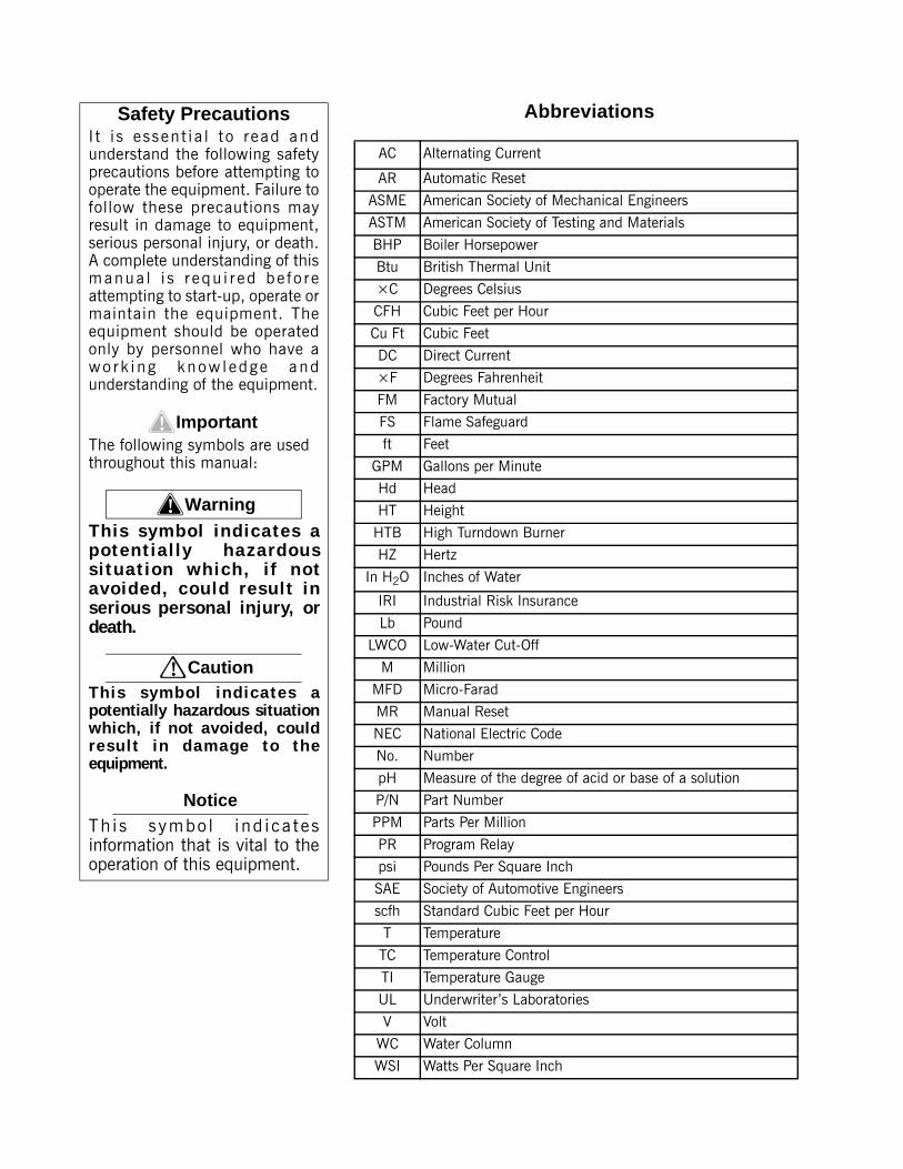
AbbreviationsSafety PrecautionsI t i s essent ia l to read andunderstand the following safetyprecautions before attempting tooperate the equipment. Failure tofollow these precautions mayresult in damage to equipment,serious personal injury, or death.A complete understanding of thismanua l i s r equ i r ed be fo r eattempting to start-up, operate ormaintain the equipment. Theequipment should be operatedonly by personnel who have awo rk i ng know ledge andunderstanding of the equipment.
Important!The following symbols are used throughout this manual:
! WarningThis symbol ind ica tes apo ten t ia l l y hazardouss i tua t ion wh ich , i f no tavo ided, cou ld resu l t inserious personal injury, ordeath.
! CautionTh is symbo l ind ica tes apotentially hazardous situationwhich, if not avoided, couldresu l t in damage to theequipment.
NoticeTh is symbo l ind i ca tesinformation that is vital to theoperation of this equipment.
AC Alternating Current
AR Automatic Reset
ASME American Society of Mechanical Engineers
ASTM American Society of Testing and Materials
BHP Boiler Horsepower
Btu British Thermal Unit
×C Degrees Celsius
CFH Cubic Feet per Hour
Cu Ft Cubic Feet
DC Direct Current
×F Degrees Fahrenheit
FM Factory Mutual
FS Flame Safeguard
ft Feet
GPM Gallons per Minute
Hd Head
HT Height
HTB High Turndown Burner
HZ Hertz
In H2O Inches of Water
IRI Industrial Risk Insurance
Lb Pound
LWCO Low-Water Cut-Off
M Million
MFD Micro-Farad
MR Manual Reset
NEC National Electric Code
No. Number
pH Measure of the degree of acid or base of a solution
P/N Part Number
PPM Parts Per Million
PR Program Relay
psi Pounds Per Square Inch
SAE Society of Automotive Engineers
scfh Standard Cubic Feet per Hour
T Temperature
TC Temperature Control
TI Temperature Gauge
UL Underwriter’s Laboratories
V Volt
WC Water Column
WSI Watts Per Square Inch

Manual Part No. 750-225 4-07
Printed in U.S.A.
© Cleaver-Brooks 2007
NOTE: If you have a CB-HAWK-ICS Boiler Management Control System, refer to CB-HAWK ICS Installation, Operating and Service Manual No. 750-229 during initial start up, and when referencing Chapters 5, 6, and 7 in this manual.
MODEL CBRPACKAGED BOILER
Operation, Service, and Parts Manual
125 through 800 hpFuel: Light Oil, Heavy Oil Gas or Combination
Please direct purchase orders for replacement manuals to your local Cleaver-Brooks authorized representative.

DO NOT OPERATE, SERVICE, OR REPAIR THIS EQUIPMENT UNLESS YOU FULLY UNDERSTAND ALL APPLI-CABLE SECTIONS OF THIS MANUAL.
DO NOT ALLOW OTHERS TO OPERATE, SERVICE, OR REPAIR THIS EQUIPMENT UNLESS THEY FULLY UN-DERSTAND ALL APPLICABLE SECTIONS OF THIS MANUAL.
FAILURE TO FOLLOW ALL APPLICABLE WARNINGS AND INSTRUCTIONS MAY RESULT IN SEVERE PER-SONAL INJURY OR DEATH.
! DANGERWARNING
TO: Owners, Operatrors, and/or Maintenance Personnel
This operating manual presents information that will help to properly operate and care for the equipment. Study its contents carefully. The unit will provide good service and continued operation if proper operating and maintenance instructions are fol-lowed. No attempt should be made to operate the unit until the principles of operation and all of the components are thoroughly understood. Failure to follow all applicable instructions and warnings may result in severe personal injury or death.
It is the responsibility of the owner to train and advise not only his or her personnel, but the contractors' personnel who are servicing, repairing or operating the equipment, in all safety aspects.
Cleaver-Brooks equipment is designed and engineered to give long life and excellent service on the job. The electrical and mechanical devices supplied as part of the unit were chosen because of their known ability to perform; however, proper oper-ating techniques and maintenance procedures must be followed at all times. Although these components afford a high degree of protection and safety, operation of equipment is not to be considered free from all dangers and hazards inherent in handling and firing of fuel.
Any “automatic” features included in the design do not relieve the attendant of any responsibility. Such features merely free him of certain repetitive chores and give him more time to devote to the proper upkeep of equipment.
It is solely the operator’s responsibility to properly operate and maintain the equipment. No amount of written instructions can replace intelligent thinking and reasoning and this manual is not intended to relieve the operating personnel of the responsibility for proper operation. On the other hand, a thorough understanding of this manual is required before attempting to operate, maintain, service, or repair this equipment.
Because of state, local, or other applicable codes, there are a variety of electric controls and safety devices which vary consid-erably from one boiler to another. This manual contains information designed to show how a basic burner operates.
Operating controls will normally function for long periods of time and we have found that some operators become lax in their daily or monthly testing, assuming that normal operation will continue indefinitely. Malfunctions of controls lead to uneco-nomical operation and damage and, in most cases, these conditions can be traced directly to carelessness and deficiencies in testing and maintenance.
It is recommended that a boiler room log or record be maintained. Recording of daily, weekly, monthly and yearly maintenance activities and recording of any unusual operation will serve as a valuable guide to any necessary investigation.
Most instances of major boiler damage are the result of operation with low water. We cannot emphasize too strongly the need for the operator to periodically check his low water controls and to follow good maintenance and testing practices. Cross-con-necting piping to low water devices must be internally inspected periodically to guard against any stoppages which could ob-struct the free flow of water to the low water devices. Float bowls of these controls must be inspected frequently to check for the presence of foreign substances that would impede float ball movement.
The waterside condition of the pressure vessel is of extreme importance. Waterside surfaces should be inspected frequently to check for the presence of any mud, sludge, scale or corrosion.
The services of a qualified water treating company or a water consultant to recommend the proper boiler water treating prac-tices are essential.
The operation of this equipment by the owner and his or her operating personnel must comply with all requirements or regu-lations of his insurance company and/or other authority having jurisdiction. In the event of any conflict or inconsistency be-tween such requirements and the warnings or instructions contained herein, please contact Cleaver-Brooks before proceeding.
i
TABLE OF CONTENTS
CHAPTER 1. BASICS OF FIRETUE OPERTIONA. GENERAL . . . . . . . . . . . . . . . . . . . . . . . . . . . . . . . . . . . . . . . . . . . . . . . . . . . . . .1-3B. THE BOILER . . . . . . . . . . . . . . . . . . . . . . . . . . . . . . . . . . . . . . . . . . . . . . . . . . . .1-3C. CONSTRUCTION . . . . . . . . . . . . . . . . . . . . . . . . . . . . . . . . . . . . . . . . . . . . . . . . .1-4D. STEAM CONTROLS (ALL FUELS) . . . . . . . . . . . . . . . . . . . . . . . . . . . . . . . . . . . . .1-5E. HOT WATER CONTROLS (ALL FUELS) . . . . . . . . . . . . . . . . . . . . . . . . . . . . . . . . . .1-6F. IFGR COMPONENTS . . . . . . . . . . . . . . . . . . . . . . . . . . . . . . . . . . . . . . . . . . . . . . .1-7
CHAPTER 2. BURNER OPERATION AND CONTROLA. THE BURNER . . . . . . . . . . . . . . . . . . . . . . . . . . . . . . . . . . . . . . . . . . . . . . . . . . .2-3B. CONTROL AND COMPONENT FUNCTION . . . . . . . . . . . . . . . . . . . . . . . . . . . . . . .2-4C. COMPONENTS COMMON TO ALL BOILERS . . . . . . . . . . . . . . . . . . . . . . . . . . . . . .2-4D. CONTROLS FOR GAS FIRING . . . . . . . . . . . . . . . . . . . . . . . . . . . . . . . . . . . . . . . .2-7E. CONTROLS COMMON TO OIL-FIRED BOILERS (INCLUDING COMBINATION) . . . . . . . . . . . . . . . . . . . . . . . . . . . . . . . . . . . . . . . . . .2-8F. ADDITIONAL CONTROLS FOR HEAVY OIL . . . . . . . . . . . . . . . . . . . . . . . . . . . . . .2-12G. CONTROLS FOR COMBINATION BURNERS ONLY . . . . . . . . . . . . . . . . . . . . . . . .2-15H. COMBUSTION AIR . . . . . . . . . . . . . . . . . . . . . . . . . . . . . . . . . . . . . . . . . . . . . .2-15I. AUTOMATIC IGNITION . . . . . . . . . . . . . . . . . . . . . . . . . . . . . . . . . . . . . . . . . . . .2-15J. ATOMIZING AIR . . . . . . . . . . . . . . . . . . . . . . . . . . . . . . . . . . . . . . . . . . . . . . . . .2-16K. OIL FUEL FLOW - LIGHT OIL . . . . . . . . . . . . . . . . . . . . . . . . . . . . . . . . . . . . . . .2-17LOIL FUEL FLOW - HEAVY OIL . . . . . . . . . . . . . . . . . . . . . . . . . . . . . . . . . . . . . . . .2-17M. GAS FUEL FLOW . . . . . . . . . . . . . . . . . . . . . . . . . . . . . . . . . . . . . . . . . . . . . . .2-20N. MODULATING FIRING . . . . . . . . . . . . . . . . . . . . . . . . . . . . . . . . . . . . . . . . . . . 2-21
CHAPTER 3. WATERSIDE CARE AND REQUIREMENTS
A. GENERAL . . . . . . . . . . . . . . . . . . . . . . . . . . . . . . . . . . . . . . . . . . . . . . . . . . . . . .3-3B. WATER REQUIREMENTS . . . . . . . . . . . . . . . . . . . . . . . . . . . . . . . . . . . . . . . . . . .3-3C. WATER TREATMENT . . . . . . . . . . . . . . . . . . . . . . . . . . . . . . . . . . . . . . . . . . . . . .3-8D.CLEANING . . . . . . . . . . . . . . . . . . . . . . . . . . . . . . . . . . . . . . . . . . . . . . . . . . . . . .3-8E. BOIL-OUT OF A NEW UNIT . . . . . . . . . . . . . . . . . . . . . . . . . . . . . . . . . . . . . . . . .3-9F. WASHING OUT . . . . . . . . . . . . . . . . . . . . . . . . . . . . . . . . . . . . . . . . . . . . . . . . .3-11G. BLOWDOWN STEAM BOILER . . . . . . . . . . . . . . . . . . . . . . . . . . . . . . . . . . . . . . .3-12H. PERIODIC INSPECTION . . . . . . . . . . . . . . . . . . . . . . . . . . . . . . . . . . . . . . . . . . .3-15I. PREPARATION FOR EXTENDED LAY-UP . . . . . . . . . . . . . . . . . . . . . . . . . . . . . . . .3-16
CHAPTER 4. SEQUENCE OF OPERATION
A. GENERAL . . . . . . . . . . . . . . . . . . . . . . . . . . . . . . . . . . . . . . . . . . . . . . . . . . . . . 4-3B. CIRCUIT AND INTERLOCK CONTROLS . . . . . . . . . . . . . . . . . . . . . . . . . . . . . . . . 4-3C. SEQUENCE OF OPERATION - OIL OR GAS . . . . . . . . . . . . . . . . . . . . . . . . . . . . . . 4-5D. FLAME LOSS SEQUENCE . . . . . . . . . . . . . . . . . . . . . . . . . . . . . . . . . . . . . . . . . . 4-7
ii

CHAPTER 5. STARTING AND OPERATING INSTRUCTIONS
A. GENERAL PREPARATION FOR START-UP, ALL FUELS . . . . . . . . . . . . . . . . . . . . . . . 5-3B. CONTROL SETTINGS - STEAM AND HOT WATER . . . . . . . . . . . . . . . . . . . . . . . . . . 5-4C. GAS PILOT . . . . . . . . . . . . . . . . . . . . . . . . . . . . . . . . . . . . . . . . . . . . . . . . . . . . . 5-5D. ATOMIZING AIR . . . . . . . . . . . . . . . . . . . . . . . . . . . . . . . . . . . . . . . . . . . . . . . . . 5-6E. FIRING PREPARATIONS FOR NO. 2 OIL (SERIES 100-200) . . . . . . . . . . . . . . . . . . 5-7F. FIRING PREPARATION FOR NO. 6 OIL (SERIES 400-600) . . . . . . . . . . . . . . . . . . . . 5-8G. FIRING PREPARATIONS FOR GAS (SERIES 200-400-700) . . . . . . . . . . . . . . . . . . 5-10H. IFGR SETUP . . . . . . . . . . . . . . . . . . . . . . . . . . . . . . . . . . . . . . . . . . . . . . . . . . . 5-11I. START-UP, OPERATING AND SHUTDOWN - ALL FUELS . . . . . . . . . . . . . . . . . . . . . 5-14J. CONTROL OPERATIONAL TEST AND CHECKS . . . . . . . . . . . . . . . . . . . . . . . . . . . 5-15
CHAPTER 6. ADJUSTMENT PROCEDURES
A. GENERAL . . . . . . . . . . . . . . . . . . . . . . . . . . . . . . . . . . . . . . . . . . . . . . . . . . . . . . . .6-3B. LINKAGE - MODULATING MOTOR AND AIR DAMPER . . . . . . . . . . . . . . . . . . . . . . . .6-3C. MODULATING MOTOR . . . . . . . . . . . . . . . . . . . . . . . . . . . . . . . . . . . . . . . . . . . . . .6-5D. MODULATING MOTOR SWITCHES - LOW FIRE AND HIGH FIRE . . . . . . . . . . . . . . . . .6-5E. BURNER OPERATING CONTROLS -GENERAL . . . . . . . . . . . . . . . . . . . . . . . . . . . . . .6-6F. MODULATING PRESSURE CONTROL (Steam) . . . . . . . . . . . . . . . . . . . . . . . . . . . . . . .6-9G. OPERATING LIMIT PRESSURE CONTROL (Steam) . . . . . . . . . . . . . . . . . . . . . . . . . . .6-9H. HIGH LIMIT PRESSURE CONTROL (Steam) . . . . . . . . . . . . . . . . . . . . . . . . . . . . . . . .6-9I. MODULATING TEMPERATURE CONTROL (Hot Water) . . . . . . . . . . . . . . . . . . . . . . . . .6-9J. OPERATING LIMIT TEMPERATURE CONTROL (Hot Water) . . . . . . . . . . . . . . . . . . . .6-10K. HIGH LIMIT TEMPERATURE CONTROL (Hot Water) . . . . . . . . . . . . . . . . . . . . . . . . .6-10L. LOW WATER CUTOFF DEVICES (Steam and Hot Water) . . . . . . . . . . . . . . . . . . . . . . .6-10M. COMBUSTION AIR PROVING SWITCH . . . . . . . . . . . . . . . . . . . . . . . . . . . . . . . . . .6-10N. ATOMIZING AIR PROVING SWITCH . . . . . . . . . . . . . . . . . . . . . . . . . . . . . . . . . . . .6-11O. GAS PILOT FLAME ADJUSTMENT . . . . . . . . . . . . . . . . . . . . . . . . . . . . . . . . . . . . . .6-11P. GAS PRESSURE AND FLOW INFORMATION . . . . . . . . . . . . . . . . . . . . . . . . . . . . . . .6-13Q. GAS FUEL CONSUMPTION ADJUSTMENT . . . . . . . . . . . . . . . . . . . . . . . . . . . . . . . .6-15R. LOW-GAS-PRESSURE SWITCH . . . . . . . . . . . . . . . . . . . . . . . . . . . . . . . . . . . . . . . .6-19S. HIGH-GAS-PRESSURE SWITCH . . . . . . . . . . . . . . . . . . . . . . . . . . . . . . . . . . . . . . .6-19T. FUEL OIL PRESSURE AND TEMPERATURE - GENERAL . . . . . . . . . . . . . . . . . . . . . .6-19U. FUEL OIL COMBUSTION ADJUSTMENT . . . . . . . . . . . . . . . . . . . . . . . . . . . . . . . . .6-20V. BURNER DRAWER ADJUSTMENT . . . . . . . . . . . . . . . . . . . . . . . . . . . . . . . . . . . . .6-24W. OIL DRAWER SWITCH . . . . . . . . . . . . . . . . . . . . . . . . . . . . . . . . . . . . . . . . . . . . .6-24X. LOW-OIL-TEMPERATURE SWITCH . . . . . . . . . . . . . . . . . . . . . . . . . . . . . . . . . . . . .6-24Y. HIGH OIL TEMPERATURE SWITCH (OPTIONAL) . . . . . . . . . . . . . . . . . . . . . . . . . . . .6-25Z. LOW OIL PRESSURE SWITCH (OPTIONAL) . . . . . . . . . . . . . . . . . . . . . . . . . . . . . . .6-25AA. ELECTRIC OIL HEATER THERMOSTAT (400 and 600 Series - Steam) . . . . . . . . . . . .6-25AB. STEAM OIL HEATER THERMOSTAT (No. 6 Oil) (400 and 600 Series - Steam) . . . . . .6-25AC. HOT WATER OIL HEATER THERMOSTAT (400 and 600 Series) . . . . . . . . . . . . . . . .6-25AD. STEAM HEATER PRESSURE REGULATOR (400 and 600 Series - Steam) . . . . . . . . .6-26
iii

CHAPTER 7. TROUBLE SHOOTING
CHAPTER 8. INSPECTION AND MAINTENANCE
A. GENERAL . . . . . . . . . . . . . . . . . . . . . . . . . . . . . . . . . . . . . . . . . . . . . . . . . . . . . . . . . . . . 8-3B. FIRESIDE CLEANING . . . . . . . . . . . . . . . . . . . . . . . . . . . . . . . . . . . . . . . . . . . . . . . . . . . . 8-4C. WATER LEVEL CONTROLS . . . . . . . . . . . . . . . . . . . . . . . . . . . . . . . . . . . . . . . . . . . . . . . . 8-4D. WATER GAUGE GLASS . . . . . . . . . . . . . . . . . . . . . . . . . . . . . . . . . . . . . . . . . . . . . . . . . . 8-5E. ELECTRICAL CONTROLS . . . . . . . . . . . . . . . . . . . . . . . . . . . . . . . . . . . . . . . . . . . . . . . . . 8-6F. FLAME SAFETY CONTROL . . . . . . . . . . . . . . . . . . . . . . . . . . . . . . . . . . . . . . . . . . . . . . . . 8-6G. OIL BURNER MAINTENANCE . . . . . . . . . . . . . . . . . . . . . . . . . . . . . . . . . . . . . . . . . . . . . . 8-9H. GAS BURNER MAINTENANCE . . . . . . . . . . . . . . . . . . . . . . . . . . . . . . . . . . . . . . . . . . . . 8-11I. MOTORIZED GAS VALVE . . . . . . . . . . . . . . . . . . . . . . . . . . . . . . . . . . . . . . . . . . . . . . . . . 8-11J. SOLENOID VALVES . . . . . . . . . . . . . . . . . . . . . . . . . . . . . . . . . . . . . . . . . . . . . . . . . . . . . 8-12K. AIR CONTROL DAMPER, LINKAGE AND CAM SPRING . . . . . . . . . . . . . . . . . . . . . . . . . . . 8-12L. FORCED DRAFT FAN . . . . . . . . . . . . . . . . . . . . . . . . . . . . . . . . . . . . . . . . . . . . . . . . . . . 8-13M. FAN/MOTOR CASSETTE REMOVAL . . . . . . . . . . . . . . . . . . . . . . . . . . . . . . . . . . . . . . . . . 8-13N. INSPECTION AND ADJUSTMENT . . . . . . . . . . . . . . . . . . . . . . . . . . . . . . . . . . . . . . . . . . 8-14O. AIRBOX GASKET INSTALLATION . . . . . . . . . . . . . . . . . . . . . . . . . . . . . . . . . . . . . . . . . . . 8-17P. FAN/MOTOR CASSETTE INSTALLATION . . . . . . . . . . . . . . . . . . . . . . . . . . . . . . . . . . . . . . 8-18Q. SAFETY VALVES . . . . . . . . . . . . . . . . . . . . . . . . . . . . . . . . . . . . . . . . . . . . . . . . . . . . . . 8-19R. FUEL OIL METERING VALVE, ADJUSTING AND RELIEF VALVES . . . . . . . . . . . . . . . . . . . . 8-19S. THE AIR PUMP AND LUBRICATING SYSTEM . . . . . . . . . . . . . . . . . . . . . . . . . . . . . . . . . . 8-24T. REFRACTORY . . . . . . . . . . . . . . . . . . . . . . . . . . . . . . . . . . . . . . . . . . . . . . . . . . . . . . . . 8-28U. OPENING AND CLOSING REAR DOOR . . . . . . . . . . . . . . . . . . . . . . . . . . . . . . . . . . . . . . 8-33V. LUBRICATION . . . . . . . . . . . . . . . . . . . . . . . . . . . . . . . . . . . . . . . . . . . . . . . . . . . . . . . . 8-35W. OIL HEATERS - ELECTRIC, STEAM, HOT WATER . . . . . . . . . . . . . . . . . . . . . . . . . . . . . . . 8-37X. COMBUSTION . . . . . . . . . . . . . . . . . . . . . . . . . . . . . . . . . . . . . . . . . . . . . . . . . . . . . . . . 8-38
CHAPTER 9. CUSTOMER SERVICE AND PARTS
iv

Notes
v
Milwaukee, Wisconsin
www.cleaver-brooks.com
Chapter 1Basics of Firetube Operation
Contents
A. GENERAL . . . . . . . . . . . . . . . . . . . . . . . . . . . . . . . . . . . . . . . . . . . . . . . . . . 1-3B. THE BOILER . . . . . . . . . . . . . . . . . . . . . . . . . . . . . . . . . . . . . . . . . . . . . . . . 1-3C. CONSTRUCTION . . . . . . . . . . . . . . . . . . . . . . . . . . . . . . . . . . . . . . . . . . . . . 1-5D. STEAM CONTROLS (ALL FUELS) . . . . . . . . . . . . . . . . . . . . . . . . . . . . . . . . . . 1-5E. HOT WATER CONTROLS (ALL FUELS) . . . . . . . . . . . . . . . . . . . . . . . . . . . . . . 1-6F. IFGR COMPONENTS . . . . . . . . . . . . . . . . . . . . . . . . . . . . . . . . . . . . . . . . . . . 1-7
Chapter 1 — Basics of Firetube Operation
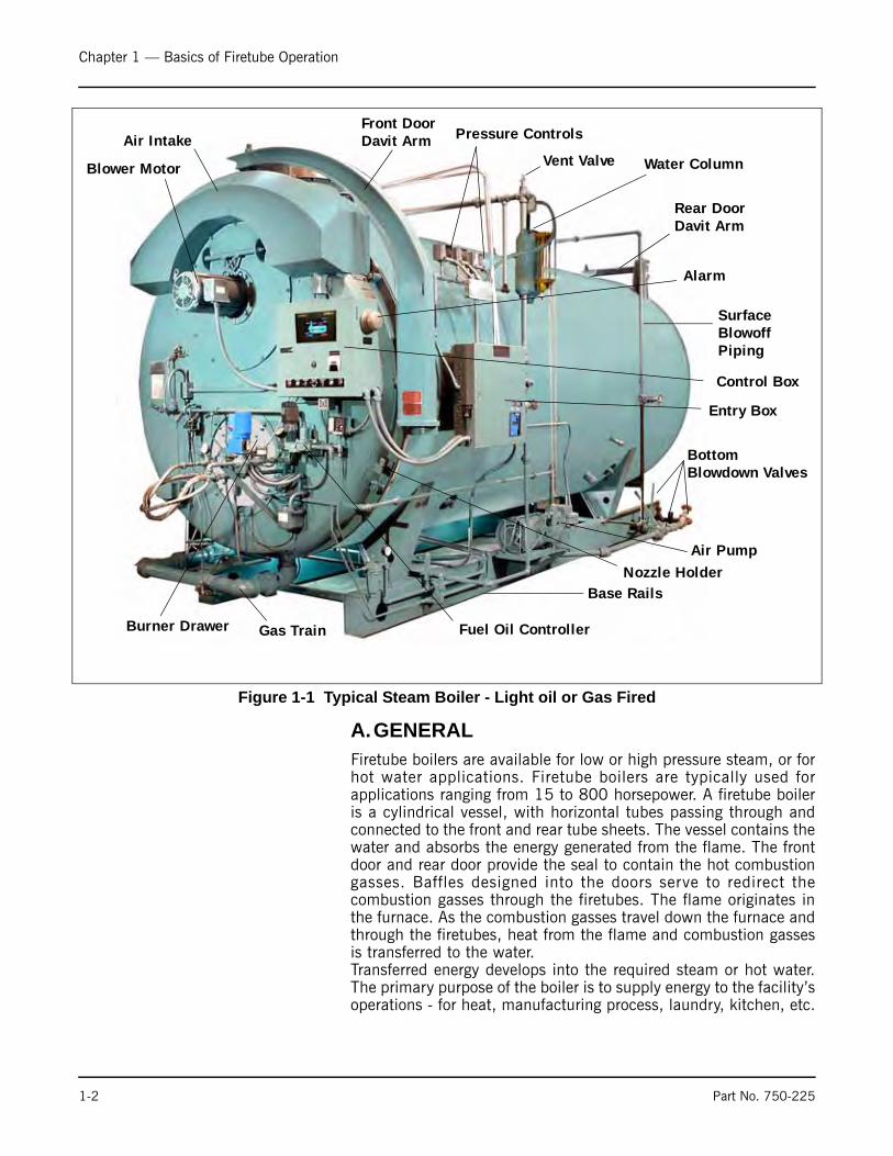
A.GENERALFiretube boilers are available for low or high pressure steam, or forhot water applications. Firetube boilers are typically used forapplications ranging from 15 to 800 horsepower. A firetube boileris a cylindrical vessel, with horizontal tubes passing through andconnected to the front and rear tube sheets. The vessel contains thewater and absorbs the energy generated from the flame. The frontdoor and rear door provide the seal to contain the hot combustiongasses. Baffles designed into the doors serve to redirect thecombustion gasses through the firetubes. The flame originates inthe furnace. As the combustion gasses travel down the furnace andthrough the firetubes, heat from the flame and combustion gassesis transferred to the water. Transferred energy develops into the required steam or hot water.The primary purpose of the boiler is to supply energy to the facility’soperations - for heat, manufacturing process, laundry, kitchen, etc.
Figure 1-1 Typical Steam Boiler - Light oil or Gas Fired
Front Door
Control Box
Blower Motor
Burner Drawer Gas Train
Pressure Controls
Water Column
Air Pump
Bottom
Vent Valve
Nozzle Holder
Fuel Oil Controller
Davit Arm
Rear Door Davit Arm
Blowdown Valves
Base Rails
SurfaceBlowoffPiping
Air Intake
Entry Box
Alarm
1-2 Part No. 750-225
Chapter 1 — Basics of Firetube Operation
The nature of the facility’s operation will dictate whether a steam orhot water boiler should be used.
The general information in this manual applies directly to Cleaver-Brooks Model CB Boilers in sizes ranging from 400 through 800boiler horsepower for the following fuels:
Series 100 Light Oil (No. 2) Series 200 Light Oil (No. 2) Or GasSeries 400 Heavy Oil (No. 6) Or GasSeries 600 Heavy Oil (No. 6) OnlySeries 700 Gas Only
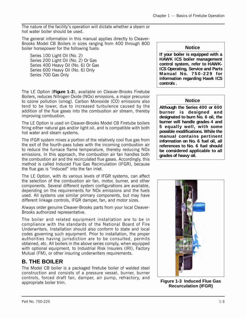
The LE Option (Figure 1-3), available on Cleaver-Brooks FiretubeBoilers, reduces Nitrogen Oxide (NOx) emissions, a major precursorto ozone pollution (smog). Carbon Monoxide (CO) emissions alsotend to be lower, due to increased turbulence caused by theaddition of the flue gases into the combustion air stream, therebyimproving combustion.
The LE Option is used on Cleaver-Brooks Model CB Firetube boilersfiring either natural gas and/or light oil, and is compatible with bothhot water and steam systems.
The IFGR system mixes a portion of the relatively cool flue gas fromthe exit of the fourth-pass tubes with the incoming combustion airto reduce the furnace flame temperature, thereby reducing NOxemissions. In this approach, the combustion air fan handles boththe combustion air and the recirculated flue gases. Accordingly, thismethod is called Induced Flue Gas Recirculation (IFGR), becausethe flue gas is “induced” into the fan inlet.
The LE Option, with its various levels of IFGR systems, can affectthe selection of the combustion air fan, motor, burner, and othercomponents. Several different system configurations are available,depending on the requirements for NOx emissions and the fuelsused. All systems use similar primary components, but may havedifferent linkage controls, IFGR damper, fan, and motor sizes.
Always order genuine Cleaver-Brooks parts from your local Cleaver-Brooks authorized representative.
The boiler and related equipment installation are to be incompliance with the standards of the National Board of FireUnderwriters. Installation should also conform to state and localcodes governing such equipment. Prior to installation, the properauthorities having jurisdiction are to be consulted, permitsobtained, etc. All boilers in the above series comply, when equippedwith optional equipment, to Industrial Risk Insurers (IRI), FactoryMutual (FM), or other insuring underwriters requirements.
B. THE BOILERThe Model CB boiler is a packaged firetube boiler of welded steelconstruction and consists of a pressure vessel, burner, burnercontrols, forced draft fan, damper, air pump, refractory, andappropriate boiler trim.
NoticeIf your boiler is equipped with aHAWK ICS boiler managementcontrol system, refer to HAWK-ICS Operating, Service and PartsManua l No . 750-229 f o rinformation regarding Hawk ICScontrols .
NoticeAlthough the Series 400 or 600burner i s des igned anddesignated to burn No. 6 oil, theburner will handle grades 4 and5 equal ly wel l , wi th somepossible modifications. While themanual conta ins per t inentinformation on No. 6 fuel oil, allreferences to No. 6 fuel shouldbe considered applicable to allgrades of heavy oil.
Figure 1-3 Induced Flue Gas Recurculation (IFGR)
Part No. 750-225 1-3
Chapter 1 — Basics of Firetube Operation
The horsepower rating of the boiler is indicated by the numbersfollowing the fuel series. Thus, CB700-600 indicates a gas-fired600 hp boiler.
The firetube construction provides some characteristics thatdifferentiate it from other boiler types. Because of its vessel size, thefiretube contains a large amount of water, allowing it to respond toload changes with minimum variation in steam pressure.
Firetube boilers are rated in boiler horsepower (BHP), which shouldnot be confused with other horsepower measurements.
Hot water is commonly used in heating applications with the boilersupplying water to the system at 180 °F to 220 °F. The operatingpressure for hot water heating systems usually is 30 psig to 125psig.
Steam boilers are designed for low pressure or high pressureapplications. Low pressure boilers are limited to 15 psig design, andare typically used for heating applications. High pressure boilers aretypically used for process loads and can have an design pressure of75 to 350psig.
Steam and hot water boilers are defined according to designpressure and operating pressure. Design pressure is the maximumpressure used in the design of the boiler for the purpose ofcalculating the minimum permissible thickness or physicalcharacteristics of the pressure vessel parts of the boiler. Typically,the safety valves are set at or below design pressure. Operatingpressure is the pressure of the boiler at which it normally operates.The operating pressure usually is maintained at a suitable levelbelow the setting of the pressure relieving valve(s) to prevent theirfrequent opening during normal operation.
The type of service that your boiler is required to provide has animportant bearing on the amount of waterside care it will require.
Feedwater equipment should be checked and ready for use. Be surethat all valves, piping, boiler feed pumps, and receivers are installedin accordance with prevailing codes and practices.
Water requirements for both steam and hot water boilers areessential to boiler life and length of service. Constant attention towater requirements will pay dividends in the form of longer life, lessdown-time, and prevention of costly repairs. Care taken in placingthe pressure vessel into initial service is vital. The waterside of newboilers and new or remodeled steam or hot water systems maycontain oil, grease or other foreign matter. A method of boiling outthe vessel to remove accumulations is described in Chapter 3.
The operator should be familiar with Chapter 3 before attempting toplace the unit into operation.
C. CONSTRUCTIONSteam boilers designed for 15 psig and hot water boilers designedfor 250°F at 160 psig or less are constructed in accordance withSection IV, Heating Boilers, of ASME Code.
! CautionWaters ide care i s o f p r imeimpor tance . Fo r spec i f i cinformation or assistance withyou r wa te r t r ea tmentrequi rements, contact yourCleaver-Brooks service and partsrepresentative. Failure to followthese instructions could result inequipment damage
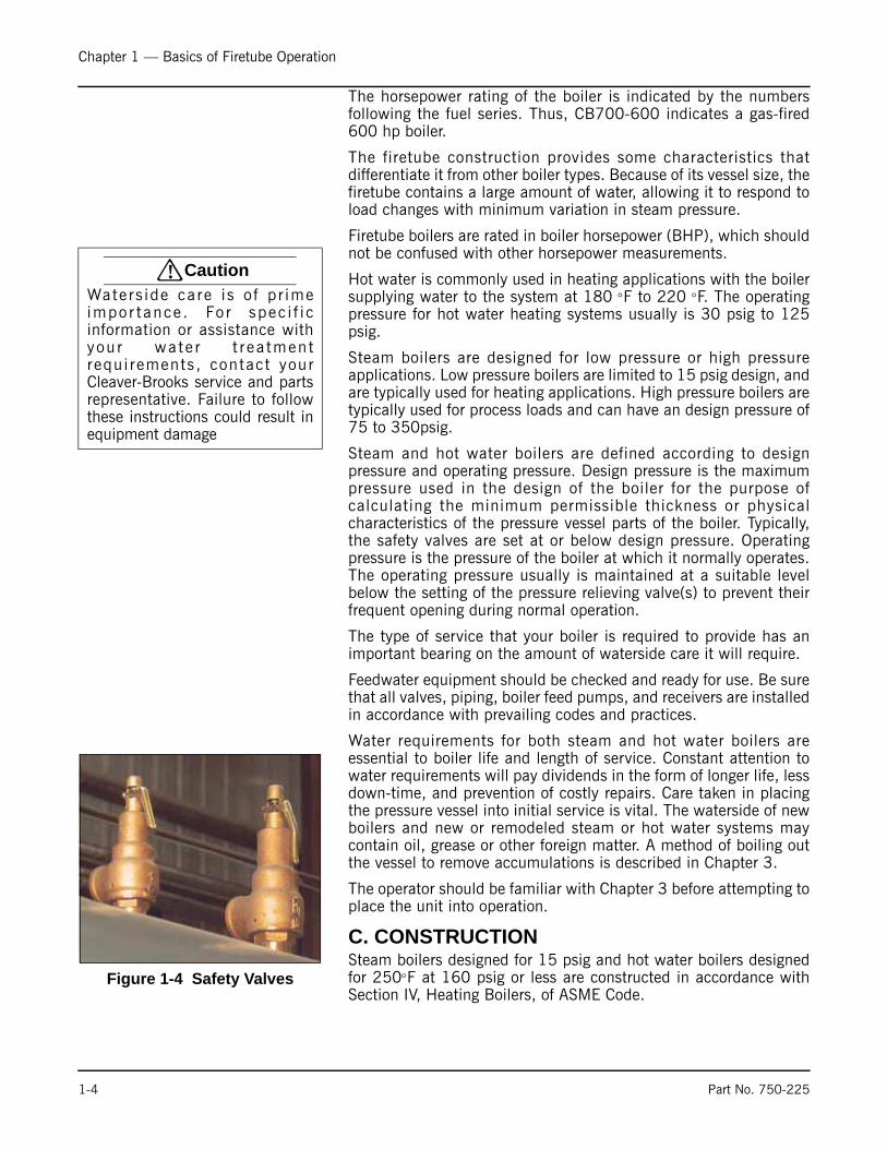
Figure 1-4 Safety Valves
1-4 Part No. 750-225

Chapter 1 — Basics of Firetube Operation
Steam boilers designed for operating pressures exceeding 15 psigare constructed in accordance with Section I, Power Boilers, of theASME Code. Hot water boilers designed for operating temperaturesabove 250×F or 160 psi are likewise built to ASME Code.
D. STEAM CONTROLS (ALL FUELS)1. Operating Limit Pressure Control (Figure 1-5): Breaks a circuit to
stop burner operation on a rise of boiler pressure at a selectedsetting. It is adjusted to stop or start the burner at a preselectedpressure setting.
2. High Limit Pressure Control (Figure 1-5): Breaks a circuit to stopburner operation on a rise of pressure above a selected setting. It isadjusted to stop the burner at a preselected pressure above theoperating limit control setting. The high limit pressure control isnormally equipped with a manual reset.
3. Modulating Pressure Control (Figure 1-5): Senses changing boilerpressures and transmits the information to the modulating motor tochange the burner firing rate when the manual-automatic switch isset on “automatic.”
4. Low-Water Cutoff and Pump Control (Figure 1-6): Float-operatedcontrol responds to the water level in the boiler. It performs twodistinct functions:
• Stops firing of the burner if water level lowers below the safe operating point. Energizes the low-water light in the control panel; also causes low-water alarm bell (optional equipment) to ring. Code requirements of some models require a manual reset type of low-water cutoff.
• Starts and stops the feedwater pump (if used) to maintain water at the proper operating level (Figure 1-6).
5. Water Column Assembly (Figure 1-6): Houses the low-water cutoffand pump control and includes the water gauge glass, gauge glassshutoff cocks.
6. Water Column Drain Valve (Figure 1-6): Provided so that the watercolumn and its piping can be flushed regularly to assist in maintainingcross-connecting piping and in keeping the float bowl clean and free ofsediment. A similar drain valve is furnished with auxiliary low-watercutoff for the same purpose.
7. Water Gauge Glass Drain Valve (Figure 1-6): Provided to flush thegauge glass.
8. Vent Valve (Figure 1-6): Allows the boiler to be vented during filling,and facilitates routine boiler inspection as required by ASME Code.
9. Stack Thermometer (not shown): Indicates stack internal temperature.
10. Safety Valve(s) (Figure 1-4): Prevent buildup over the design pressureof the pressure vessel. The size, rating and number of valves on aboiler is determined by the ASME Boiler Code. The safety valves andthe discharge piping are to be installed to conform to the ASME coderequirements. The installation of a valve is of primary importance to itsservice life. A valve must be mounted in a vertical position so thatdischarge piping and code-required drains can be properly piped toprevent buildup of back pressure and accumulation of foreign materialaround the valve seat area. Apply only a moderate amount of pipecompound to male threads and avoid overtightening, which can distortthe seats. Use only flat-jawed wrenches on the flats provided. Wheninstalling a flange-connected valve, use a new gasket and draw themounting bolts down evenly. Do not install or remove side outletvalves by using a pipe or wrench in the outlet.
Figure 1-5 Steam Controls
1. OPERATING CONTROL
2. HIGH LIMIT CONTROL
3. MODULATING CONTROL
1 2 3
! CautionDetermine that the main andauxiliary low water cutoffs andpump control are level af terinstallation and throughout theequipment ’s operat ing l i fe .Fa i lu re to fo l l ow theseinstruct ions could resul t inequipment damage.
Figure 1-6 Level Master Low Water Cut Off (LWCO)
Vent
Gauge
Drain
Gauge Glass
Valve
Glass
Valve
Valves
WaterColumnDrain
WaterColumnAssembly
Part No. 750-225 1-5
Chapter 1 — Basics of Firetube Operation
11. Auxiliary Low-water Cutoff: Breaks the circuit to stop burner operationin the event boiler water drops below the master low-water cutoffpoint. Manual reset type requires manual resetting in order to start theburner after a low-water condition.
E. HOT WATER CONTROLS (ALL FUELS)1. Water Temperature Gauge (Figure 1-8): Indicates the boiler water
temperature.
2. Operating Limit Temperature Control (Figure 1-9): Breaks a circuitto stop burner operation on a rise of boiler temperature at aselected setting. It is adjusted to stop or start the burner at apreselected operating temperature.
3. High Limit Temperature Control (Figure 1-9): Breaks a circuit tostop burner operation on a rise of temperature at a selected setting.It is adjusted to stop burner at a preselected temperature above theoperating control setting. The high limit temperature controlnormally is equipped with a manual reset.
4. Modulating Temperature Control (Figure 1-9): Senses changingboiler water temperature and transmits the information to themodulating motor to change the burner firing rate when themanual-automatic switch is set on “automatic.”
5. Low-Water Cutoff: Breaks the circuit to stop burner operation if thewater level in the boiler drops below safe operating point,activating low-water light and optional alarm bell if burner is soequipped.
6. Auxiliary Low-Water Cutoff (Not Shown) (Optional): Breaks thecircuit to stop burner operation if the water level in the boiler dropsbelow the master low-water cutoff point.
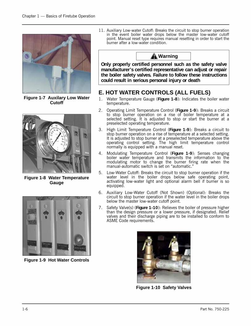
7. Safety Valve(s) (Figure 1-10): Relieves the boiler of pressure higherthan the design pressure or a lower pressure, if designated. Reliefvalves and their discharge piping are to be installed to conform toASME Code requirements.
Figure 1-7 Auxilary Low Water Cutoff
! WarningOnly properly certified personnel such as the safety valvemanufacturer’s certified representative can adjust or repairthe boiler safety valves. Failure to follow these instructionscould result in serious personal injury or death
Figure 1-8 Water Temperature Gauge
Figure 1-9 Hot Water Controls
Figure 1-10 Safety Valves
1-6 Part No. 750-225
Chapter 1 — Basics of Firetube Operation
F. IFGR COMPONENTS
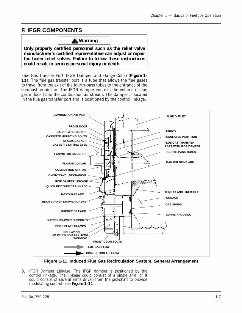
Flue Gas Transfer Port, IFGR Damper, and Flange Collar (Figure 1-11). The flue gas transfer port is a tube that allows the flue gasesto travel from the exit of the fourth-pass tubes to the entrance of thecombustion air fan. The IFGR damper controls the volume of fluegas induced into the combustion air stream. The damper is locatedin the flue gas transfer port and is positioned by the control linkage.
8. IFGR Damper Linkage. The IFGR damper is positioned by thecontrol linkage. The linkage could consist of a single arm, or itcould consist of several arms driven from the jackshaft to providemodulating control (see Figure 1-11).
! WarningOnly properly certified personnel such as the relief valvemanufacturer’s certified representative can adjust or repairthe boiler relief valves. Failure to follow these instructionscould result in serious personal injury or death.
Figure 1-11 Induced Flue Gas Recirculation System, General Arrangement
COMBUSTION AIR INLET
FRONT DOOR
CASSETTE MOUNTING BOLTS
AIRBOX GASKETCASSETTE LIFTING EYES
FAN/MOTOR CASSETTE
FLANGE COLLAR
COMBUSTION AIR FAN
OVER-TRAVEL MECHANISM
IFGR DAMPER LINKAGE
QUICK DISCONNECT LINKAGE
JACKSHAFT ARM
BURNER DRAWER
BURNER DRAWER SUPPORTS
INNER PLATE CLAMPS
FRONT DOOR BOLTS
FLUE OUTLET
AIRBOX
FLUE GAS TRANSFERPORT WITH IFGR DAMPER
FOURTH-PASS TUBES
DAMPER DRIVE ARM
THROAT AND LINER TILE
FURNACE
GAS SPUDS
BURNER HOUSING
FLUE GAS FLOW
COMBUSTION AIR FLOW
BACKPLATE GASKET
WINDBOX
INSULATED PARTITION
REAR BURNER DRAWER GASKET
INSULATION (20-30 PPM NOx SYSTEMS)
Part No. 750-225 1-7

Chapter 1 — Basics of Firetube Operation
9. Over-Travel Mechanism (Figure 1-12). The over-travel mechanismhas two functions. It allows the linkage to pass through the frontdoor, and it allows jackshaft rotation to exceed (over travel) IFGRlinkage movement. A set of springs allows the linkage to stay in afixed position while the jackshaft rotates.
10. Fuel Change-Over Linkage (Figure 1-12). When a boiler isequipped to fire either gas or oil (dual-fuel boilers), and therequired NOx levels are below 60 ppm on natural gas, a dual-linkage arrangement is used to provide the different recirculationrates required for each fuel. Two jackshaft drive arms are provided,one for oil and one for gas. The linkage is manually connected tothe appropriate arm, based on the fuel being used. On dual-fuelboilers with two jackshaft drive arms, as defined above, a proximityswitch is used to prove that the correct linkage connection is made.(Refer to the wiring diagram provided with the boiler.)
Fan/Motor Cassette (Figure 1-13). The fan and motor assembliesare designed as a cassette so that they can be removed from thefront of the boiler, without opening the front door. The front doordavit arm can be used to remove the assembly.
11. Burner Drawer (Figure 1-11). The gas spudding pattern for theIFGR system may be different than that of a non-IFGR, High-
Figure 1-12 Over Travel and Fuel Change-over Linkage
Figure 1-13 Fan / Motor Cassette
COME-ALONGOR
CHAIN
BACK PLATE GASKET
INLET GASKET
FAN/MOTOR CASSETTE
DAVIT ARM
HEAVY TURNBUCKLE
1-8 Part No. 750-225
Chapter 1 — Basics of Firetube Operation
Turndown CB Burner of the same horsepower (HP) modeldesignation.
12. Combustion Air Inlet (Figure 1-13). The combustion air inlets arelocated at the top of the front door. Air enters from the rear of theair inlet shrouds, which reduces the sound level and captures heatfrom the boiler and stack flue outlet.
13. Front Door Installation (Figure 1-13). If NOx emissions are below60 ppm, the front door is insulated inside to control temperaturebuild up. The insulation is held in place with wire mesh.
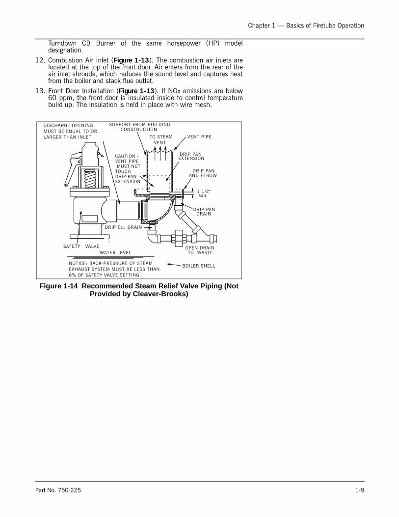
Figure 1-14 Recommended Steam Relief Valve Piping (Not Provided by Cleaver-Brooks)
DISCHARGE OPENING MUST BE EQUAL TO OR LARGER THAN INLET
CAUTION - VENT PIPE MUST NOT TOUCH DRIP PAN EXTENSION
SUPPORT FROM BUILDINGCONSTRUCTION
VENT
DRIP PANEXTENSION
DRIP PANAND ELBOW
DRIP PANDRAIN
VENT PIPE
OPEN DRAINTO WASTE
BOILER SHELL
SAFETY VALVE
DRIP ELL DRAIN
WATER LEVEL
NOTICE: BACK-PRESSURE OF STEAM EXHAUST SYSTEM MUST BE LESS THAN 6% OF SAFETY VALVE SETTING.
TO STEAM
1 1/2”MIN.
Part No. 750-225 1-9
Chapter 1 — Basics of Firetube Operation
Notes
1-10 Part No. 750-294

Milwaukee, Wisconsin
www.cleaver-brooks.com
Chapter 2Burner Operation and Control
ContentsA. THE BURNER . . . . . . . . . . . . . . . . . . . . . . . . . . . . . . . . . . . . . . 2-3B. CONTROL AND COMPONENT FUNCTION . . . . . . . . . . . . . . . . . . 2-4C. COMPONENTS COMMON TO ALL BOILERS . . . . . . . . . . . . . . . . . 2-4D. CONTROLS FOR GAS FIRING . . . . . . . . . . . . . . . . . . . . . . . . . . . 2-7E. CONTROLS COMMON TO OIL-FIRED BOILERS (INCLUDING COMBINATION) . . . . . . . . . . . . . . . . . . . . . . . . . . . . . 2-8F. ADDITIONAL CONTROLS FOR HEAVY OIL . . . . . . . . . . . . . . . . . . 2-12G. CONTROLS FOR COMBINATION BURNERS ONLY . . . . . . . . . . . 2-15H. COMBUSTION AIR . . . . . . . . . . . . . . . . . . . . . . . . . . . . . . . . . . 2-15I. AUTOMATIC IGNITION . . . . . . . . . . . . . . . . . . . . . . . . . . . . . . . 2-15J. ATOMIZING AIR . . . . . . . . . . . . . . . . . . . . . . . . . . . . . . . . . . . . 2-16K. OIL FUEL FLOW - LIGHT OIL . . . . . . . . . . . . . . . . . . . . . . . . . . 2-17L. OIL FUEL FLOW - HEAVY OIL . . . . . . . . . . . . . . . . . . . . . . . . . . 2-17M. GAS FUEL FLOW . . . . . . . . . . . . . . . . . . . . . . . . . . . . . . . . . . 2-20N. MODULATING FIRING . . . . . . . . . . . . . . . . . . . . . . . . . . . . . . . 2-21
Chapter 2 — Burner Operation and Control
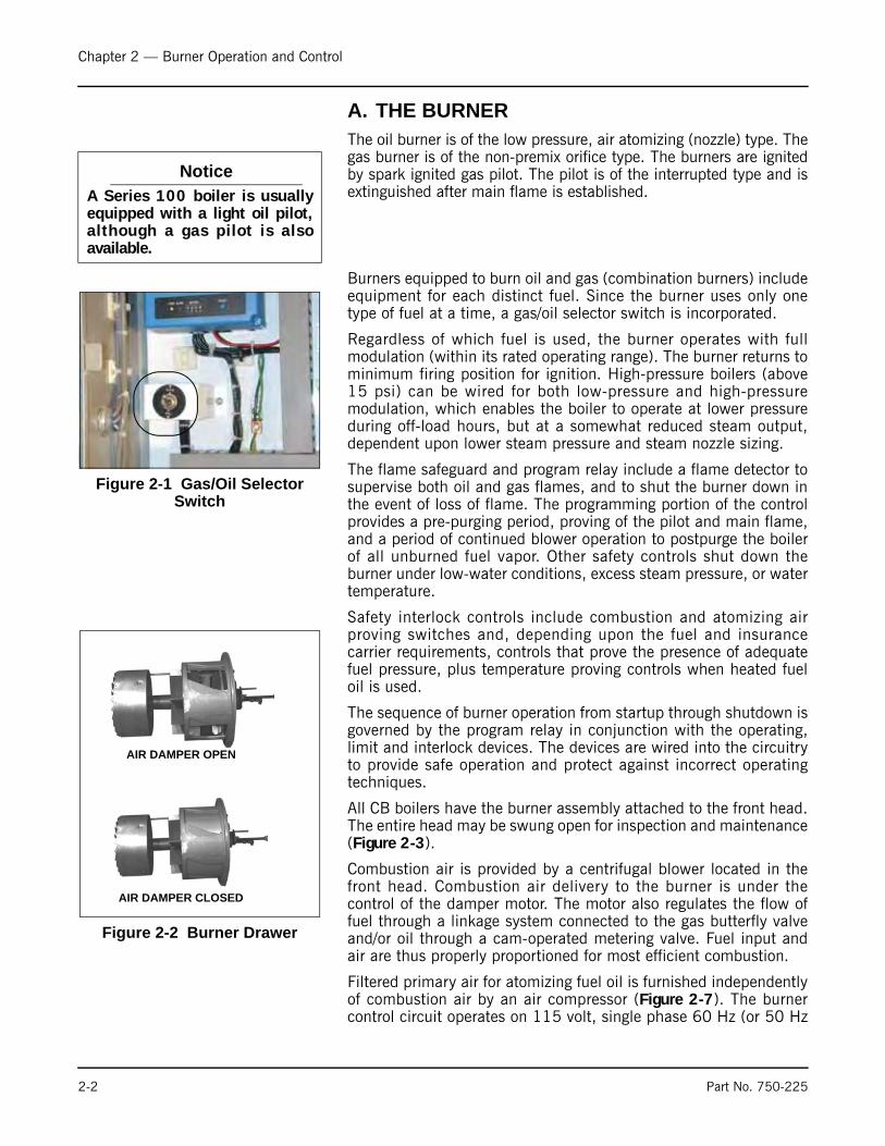
A. THE BURNER The oil burner is of the low pressure, air atomizing (nozzle) type. Thegas burner is of the non-premix orifice type. The burners are ignitedby spark ignited gas pilot. The pilot is of the interrupted type and isextinguished after main flame is established.
Burners equipped to burn oil and gas (combination burners) includeequipment for each distinct fuel. Since the burner uses only onetype of fuel at a time, a gas/oil selector switch is incorporated.
Regardless of which fuel is used, the burner operates with fullmodulation (within its rated operating range). The burner returns tominimum firing position for ignition. High-pressure boilers (above15 psi) can be wired for both low-pressure and high-pressuremodulation, which enables the boiler to operate at lower pressureduring off-load hours, but at a somewhat reduced steam output,dependent upon lower steam pressure and steam nozzle sizing.
The flame safeguard and program relay include a flame detector tosupervise both oil and gas flames, and to shut the burner down inthe event of loss of flame. The programming portion of the controlprovides a pre-purging period, proving of the pilot and main flame,and a period of continued blower operation to postpurge the boilerof all unburned fuel vapor. Other safety controls shut down theburner under low-water conditions, excess steam pressure, or watertemperature.
Safety interlock controls include combustion and atomizing airproving switches and, depending upon the fuel and insurancecarrier requirements, controls that prove the presence of adequatefuel pressure, plus temperature proving controls when heated fueloil is used.
The sequence of burner operation from startup through shutdown isgoverned by the program relay in conjunction with the operating,limit and interlock devices. The devices are wired into the circuitryto provide safe operation and protect against incorrect operatingtechniques.
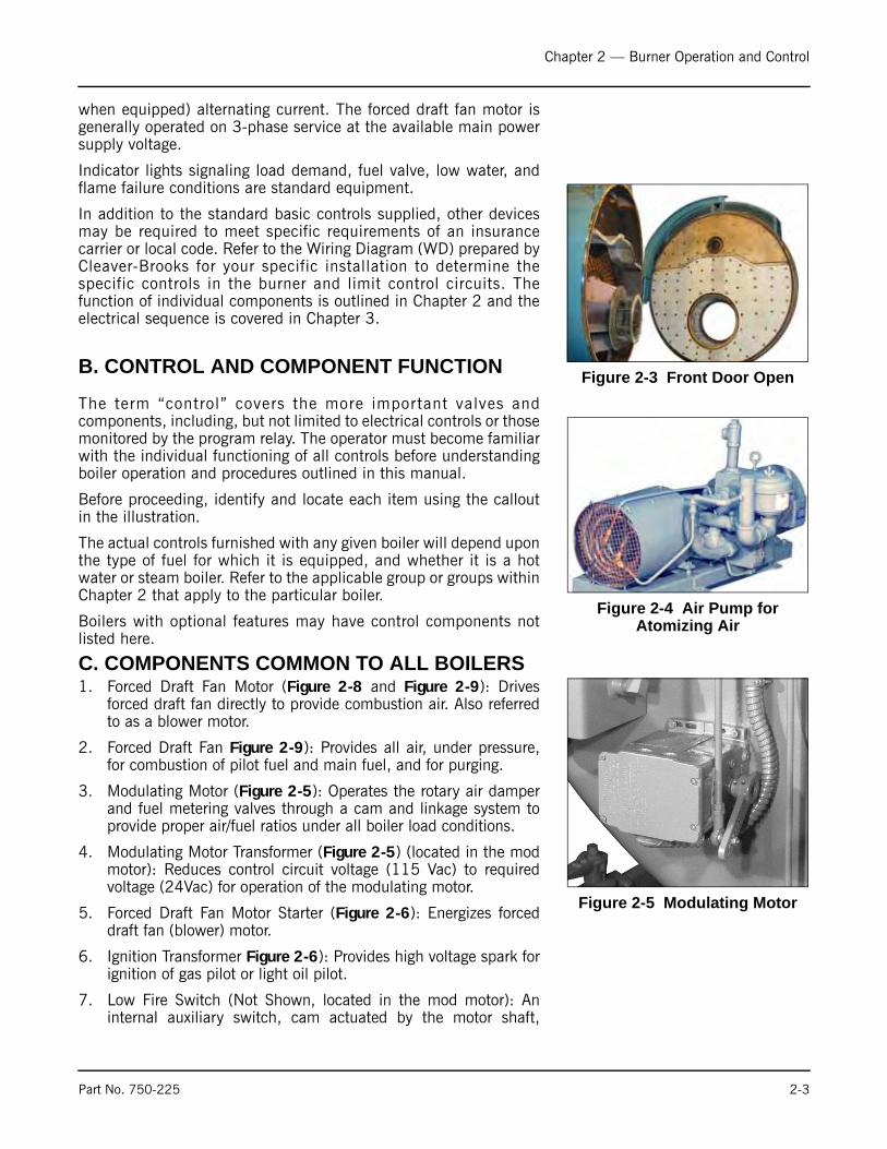
All CB boilers have the burner assembly attached to the front head.The entire head may be swung open for inspection and maintenance(Figure 2-3).
Combustion air is provided by a centrifugal blower located in thefront head. Combustion air delivery to the burner is under thecontrol of the damper motor. The motor also regulates the flow offuel through a linkage system connected to the gas butterfly valveand/or oil through a cam-operated metering valve. Fuel input andair are thus properly proportioned for most efficient combustion.
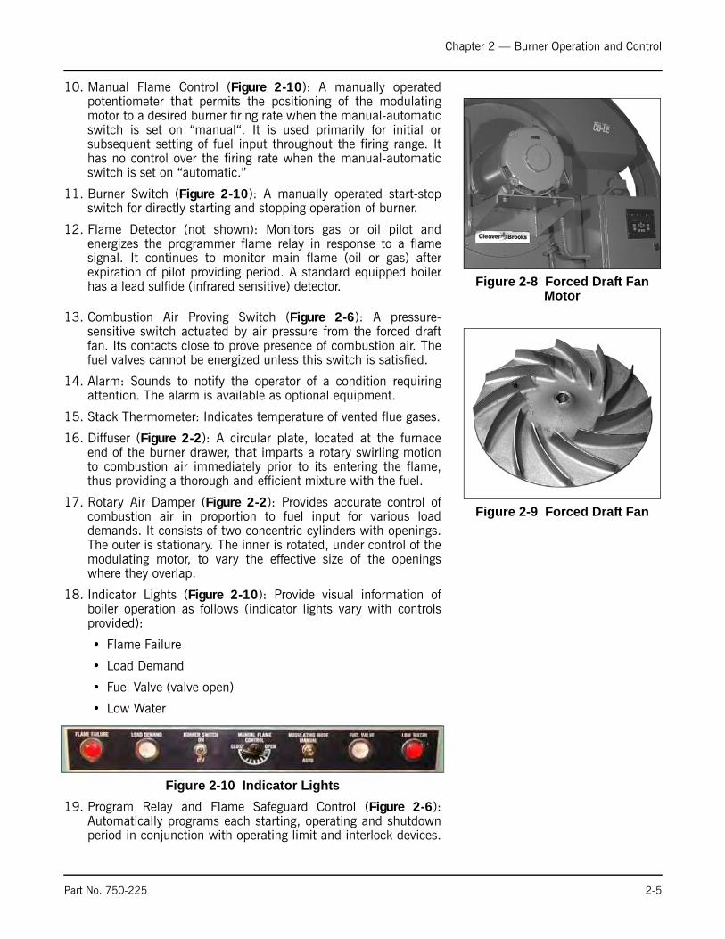
Filtered primary air for atomizing fuel oil is furnished independentlyof combustion air by an air compressor (Figure 2-7). The burnercontrol circuit operates on 115 volt, single phase 60 Hz (or 50 Hz
NoticeA Series 100 boiler is usuallyequipped with a light oil pilot,although a gas pilot is alsoavailable.
Figure 2-1 Gas/Oil Selector Switch
Figure 2-2 Burner Drawer
AIR DAMPER OPEN
AIR DAMPER CLOSED
2-2 Part No. 750-225
Chapter 2 — Burner Operation and Control
when equipped) alternating current. The forced draft fan motor isgenerally operated on 3-phase service at the available main powersupply voltage.
Indicator lights signaling load demand, fuel valve, low water, andflame failure conditions are standard equipment.
In addition to the standard basic controls supplied, other devicesmay be required to meet specific requirements of an insurancecarrier or local code. Refer to the Wiring Diagram (WD) prepared byCleaver-Brooks for your specific installation to determine thespecific controls in the burner and limit control circuits. Thefunction of individual components is outlined in Chapter 2 and theelectrical sequence is covered in Chapter 3.
B. CONTROL AND COMPONENT FUNCTION
The term “control” covers the more important valves andcomponents, including, but not limited to electrical controls or thosemonitored by the program relay. The operator must become familiarwith the individual functioning of all controls before understandingboiler operation and procedures outlined in this manual.
Before proceeding, identify and locate each item using the calloutin the illustration.
The actual controls furnished with any given boiler will depend uponthe type of fuel for which it is equipped, and whether it is a hotwater or steam boiler. Refer to the applicable group or groups withinChapter 2 that apply to the particular boiler.
Boilers with optional features may have control components notlisted here.
C. COMPONENTS COMMON TO ALL BOILERS1. Forced Draft Fan Motor (Figure 2-8 and Figure 2-9): Drives
forced draft fan directly to provide combustion air. Also referredto as a blower motor.
2. Forced Draft Fan Figure 2-9): Provides all air, under pressure,for combustion of pilot fuel and main fuel, and for purging.
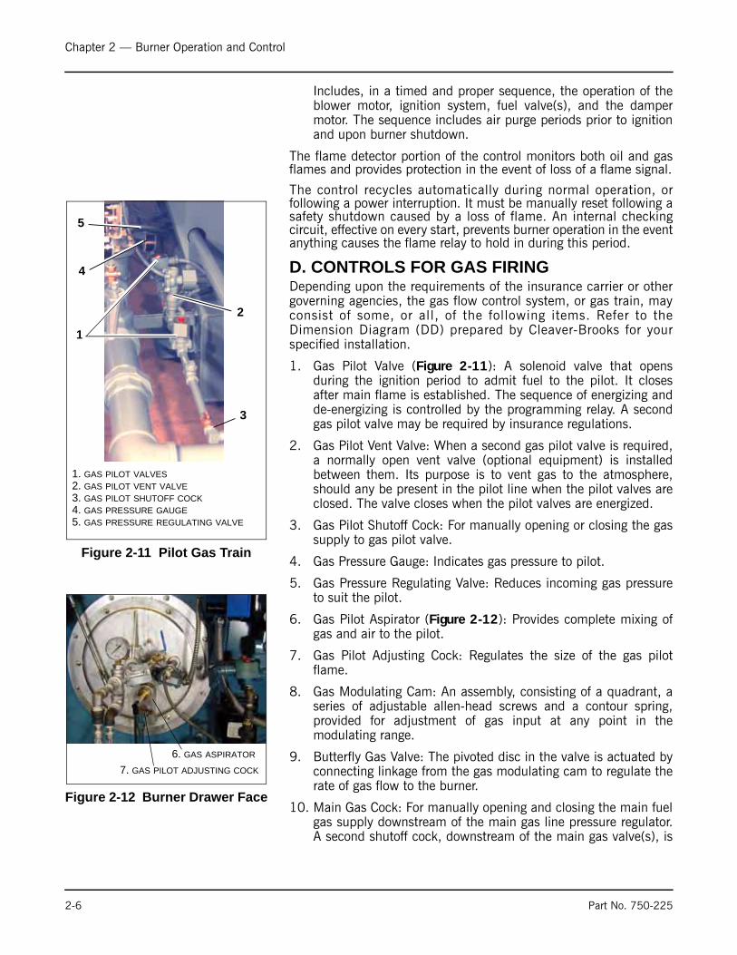
3. Modulating Motor (Figure 2-5): Operates the rotary air damperand fuel metering valves through a cam and linkage system toprovide proper air/fuel ratios under all boiler load conditions.
4. Modulating Motor Transformer (Figure 2-5) (located in the modmotor): Reduces control circuit voltage (115 Vac) to requiredvoltage (24Vac) for operation of the modulating motor.
5. Forced Draft Fan Motor Starter (Figure 2-6): Energizes forceddraft fan (blower) motor.
6. Ignition Transformer Figure 2-6): Provides high voltage spark forignition of gas pilot or light oil pilot.
7. Low Fire Switch (Not Shown, located in the mod motor): Aninternal auxiliary switch, cam actuated by the motor shaft,
Figure 2-3 Front Door Open
Figure 2-4 Air Pump for Atomizing Air
Figure 2-5 Modulating Motor
Part No. 750-225 2-3

Chapter 2 — Burner Operation and Control
which must be closed to indicate that the air damper and fuelmetering valve are in the low fire position before an ignitioncycle can occur.
8. Atomizing Air Proving Switch (Figure 2-6): A pressure-sensitiveswitch actuated by air pressure from the Air Pump. Its contactsclose to prove presence of atomizing air. The fuel valves cannotbe energized unless this switch is satisfied.
9. Manual-Automatic Switch (Figure 2-10): When set at“automatic,” subsequent operation is at the command of themodulating control, which governs the position of themodulating motor in accordance with load demand. When set at“manual,” the modulating motor, through the manual flamecontrol, can be positioned at a desired burner firing rate. Theprimary purpose of the manual position is for testing and settingthe air/fuel ratio through the entire firing range.
Figure 2-6 Components and Controls
Forced Draft Fan Motor
Modulating Motor
Motor Starter
FGR Linkage
AccuLinkJackshaft
Fuel OilController
Air PumpModule
ContinuousBlowdownPiping
BottomBlowdownValves
IgnitionTransformer
Atomized AirProving Switch
Figure 2-7 Air Compressor
2-4 Part No. 750-225
Chapter 2 — Burner Operation and Control
10. Manual Flame Control (Figure 2-10): A manually operatedpotentiometer that permits the positioning of the modulatingmotor to a desired burner firing rate when the manual-automaticswitch is set on “manual“. It is used primarily for initial orsubsequent setting of fuel input throughout the firing range. Ithas no control over the firing rate when the manual-automaticswitch is set on “automatic.”
11. Burner Switch (Figure 2-10): A manually operated start-stopswitch for directly starting and stopping operation of burner.
12. Flame Detector (not shown): Monitors gas or oil pilot andenergizes the programmer flame relay in response to a flamesignal. It continues to monitor main flame (oil or gas) afterexpiration of pilot providing period. A standard equipped boilerhas a lead sulfide (infrared sensitive) detector.
13. Combustion Air Proving Switch (Figure 2-6): A pressure-sensitive switch actuated by air pressure from the forced draftfan. Its contacts close to prove presence of combustion air. Thefuel valves cannot be energized unless this switch is satisfied.
14. Alarm: Sounds to notify the operator of a condition requiringattention. The alarm is available as optional equipment.
15. Stack Thermometer: Indicates temperature of vented flue gases.
16. Diffuser (Figure 2-2): A circular plate, located at the furnaceend of the burner drawer, that imparts a rotary swirling motionto combustion air immediately prior to its entering the flame,thus providing a thorough and efficient mixture with the fuel.
17. Rotary Air Damper (Figure 2-2): Provides accurate control ofcombustion air in proportion to fuel input for various loaddemands. It consists of two concentric cylinders with openings.The outer is stationary. The inner is rotated, under control of themodulating motor, to vary the effective size of the openingswhere they overlap.
18. Indicator Lights (Figure 2-10): Provide visual information ofboiler operation as follows (indicator lights vary with controlsprovided):
• Flame Failure
• Load Demand
• Fuel Valve (valve open)
• Low Water
19. Program Relay and Flame Safeguard Control (Figure 2-6):Automatically programs each starting, operating and shutdownperiod in conjunction with operating limit and interlock devices.
Figure 2-8 Forced Draft Fan Motor
Figure 2-9 Forced Draft Fan
Figure 2-10 Indicator Lights
Part No. 750-225 2-5
Chapter 2 — Burner Operation and Control
Includes, in a timed and proper sequence, the operation of theblower motor, ignition system, fuel valve(s), and the dampermotor. The sequence includes air purge periods prior to ignitionand upon burner shutdown.
The flame detector portion of the control monitors both oil and gasflames and provides protection in the event of loss of a flame signal.
The control recycles automatically during normal operation, orfollowing a power interruption. It must be manually reset following asafety shutdown caused by a loss of flame. An internal checkingcircuit, effective on every start, prevents burner operation in the eventanything causes the flame relay to hold in during this period.
D. CONTROLS FOR GAS FIRINGDepending upon the requirements of the insurance carrier or othergoverning agencies, the gas flow control system, or gas train, mayconsist of some, or all, of the following items. Refer to theDimension Diagram (DD) prepared by Cleaver-Brooks for yourspecified installation.
1. Gas Pilot Valve (Figure 2-11): A solenoid valve that opensduring the ignition period to admit fuel to the pilot. It closesafter main flame is established. The sequence of energizing andde-energizing is controlled by the programming relay. A secondgas pilot valve may be required by insurance regulations.
2. Gas Pilot Vent Valve: When a second gas pilot valve is required,a normally open vent valve (optional equipment) is installedbetween them. Its purpose is to vent gas to the atmosphere,should any be present in the pilot line when the pilot valves areclosed. The valve closes when the pilot valves are energized.
3. Gas Pilot Shutoff Cock: For manually opening or closing the gassupply to gas pilot valve.
4. Gas Pressure Gauge: Indicates gas pressure to pilot.
5. Gas Pressure Regulating Valve: Reduces incoming gas pressureto suit the pilot.
6. Gas Pilot Aspirator (Figure 2-12): Provides complete mixing ofgas and air to the pilot.
7. Gas Pilot Adjusting Cock: Regulates the size of the gas pilotflame.
8. Gas Modulating Cam: An assembly, consisting of a quadrant, aseries of adjustable allen-head screws and a contour spring,provided for adjustment of gas input at any point in themodulating range.
9. Butterfly Gas Valve: The pivoted disc in the valve is actuated byconnecting linkage from the gas modulating cam to regulate therate of gas flow to the burner.
10. Main Gas Cock: For manually opening and closing the main fuelgas supply downstream of the main gas line pressure regulator.A second shutoff cock, downstream of the main gas valve(s), is
Figure 2-11 Pilot Gas Train
1
3
1. GAS PILOT VALVES2. GAS PILOT VENT VALVE3. GAS PILOT SHUTOFF COCK4. GAS PRESSURE GAUGE5. GAS PRESSURE REGULATING VALVE
2
4
5
Figure 2-12 Burner Drawer Face
6. GAS ASPIRATOR
7. GAS PILOT ADJUSTING COCK
2-6 Part No. 750-225

Chapter 2 — Burner Operation and Control
installed to provide a means of shutting off the gas linewhenever a test is made for leakage across the main gas valve.
11. Main Gas Valves: Electrically actuated shutoff valves that opensimultaneously to admit gas to the burner. The downstreamvalve is equipped with a “proof of closure” switch that isconnected into the pre-ignition interlock circuit.
12. Main Gas Vent Valve: A normally open solenoid valve installedbetween the two main gas valves to vent gas to the atmosphereshould any be present in the main gas line when the gas valvesare deenergized. The vent valve closes when the gas valves areenergized.
13. Low Gas Pressure Switch: A pressure-actuated switch that isclosed whenever main gas line pressure is above a preselectedpressure. Should the pressure drop below the setting, the switchcontacts open a circuit causing the main gas valve(s) to close, orprevent the burner from starting. The switch is usually equippedwith a device that must be manually reset after being tripped.
14. High Gas Pressure Switch (Not Shown): A pressure actuated switch that is closed whenever main gas line pressure is below a preselected pressure. Should the pressure rise above the setting, the switch contacts will open a circuit causing the main gas valve(s) to close, or prevent the burner from starting. The switch is usually equipped with a device that must be manually reset after being tripped.
15. Leakage Connection (Not Shown): The body of the gas valve hasa plugged opening that is used whenever it is necessary toconduct a test for possible leakage across the closed valve.
E. CONTROLS COMMON TO OIL-FIRED BOILERS (INCLUDING COMBINATION)
The following items are applicable to all oil fired or gas and oil firedboilers. Additional controls for No. 6 oil are listed in Section I.
1. Oil Drawer Switch (Figure 2-15): Opens the limit circuit if oildrawer burner gun is not latched in the forward positionrequired for burning oil.
2. Atomizing Air Proving Switch (Figure 2-16): Pressure-actuatedswitch whose contacts are closed when sufficient atomizing airpressure from the air pump is present for oil firing. Oil valve(s)will not open, or will not remain open, unless switch contactsare closed.
Figure 2-13 Gas Modulating Cam, linkage and Butterfly Valve
8
9
Figure 2-14 Main Gas Train
Main Gas Valves
Main Gas Shutoff Cocks
Vent ValveLow Gas Pressure Switch10
11
1213
Figure 2-15 Oil Drawer Switch
Part No. 750-225 2-7
Chapter 2 — Burner Operation and Control
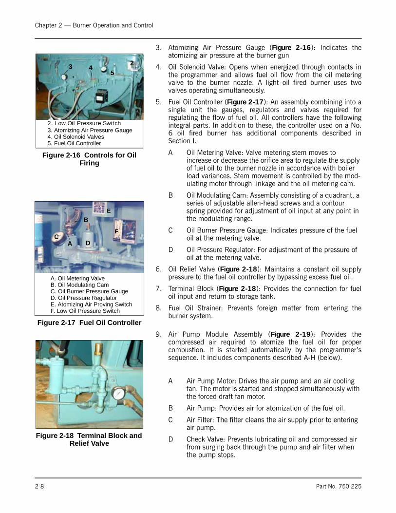
3. Atomizing Air Pressure Gauge (Figure 2-16): Indicates theatomizing air pressure at the burner gun
4. Oil Solenoid Valve: Opens when energized through contacts inthe programmer and allows fuel oil flow from the oil meteringvalve to the burner nozzle. A light oil fired burner uses twovalves operating simultaneously.
5. Fuel Oil Controller (Figure 2-17): An assembly combining into asingle unit the gauges, regulators and valves required forregulating the flow of fuel oil. All controllers have the followingintegral parts. In addition to these, the controller used on a No.6 oil fired burner has additional components described inSection I.
A Oil Metering Valve: Valve metering stem moves to increase or decrease the orifice area to regulate the supply of fuel oil to the burner nozzle in accordance with boiler load variances. Stem movement is controlled by the mod-ulating motor through linkage and the oil metering cam.
B Oil Modulating Cam: Assembly consisting of a quadrant, a series of adjustable allen-head screws and a contour spring provided for adjustment of oil input at any point in the modulating range.
C Oil Burner Pressure Gauge: Indicates pressure of the fuel oil at the metering valve.
D Oil Pressure Regulator: For adjustment of the pressure of oil at the metering valve.
6. Oil Relief Valve (Figure 2-18): Maintains a constant oil supplypressure to the fuel oil controller by bypassing excess fuel oil.
7. Terminal Block (Figure 2-18): Provides the connection for fueloil input and return to storage tank.
8. Fuel Oil Strainer: Prevents foreign matter from entering theburner system.
9. Air Pump Module Assembly (Figure 2-19): Provides thecompressed air required to atomize the fuel oil for propercombustion. It is started automatically by the programmer’ssequence. It includes components described A-H (below).
A Air Pump Motor: Drives the air pump and an air cooling fan. The motor is started and stopped simultaneously with the forced draft fan motor.
B Air Pump: Provides air for atomization of the fuel oil.
C Air Filter: The filter cleans the air supply prior to entering air pump.
D Check Valve: Prevents lubricating oil and compressed air from surging back through the pump and air filter when the pump stops.
Figure 2-16 Controls for Oil Firing
2. Low Oil Pressure Switch3. Atomizing Air Pressure Gauge4. Oil Solenoid Valves5. Fuel Oil Controller
23 45
Figure 2-17 Fuel Oil Controller
A. Oil Metering ValveB. Oil Modulating CamC. Oil Burner Pressure GaugeD. Oil Pressure Regulator
A
B
CD
E. Atomizing Air Proving SwitchF. Low Oil Pressure Switch
E
F
Figure 2-18 Terminal Block and Relief Valve
2-8 Part No. 750-225
Chapter 2 — Burner Operation and Control
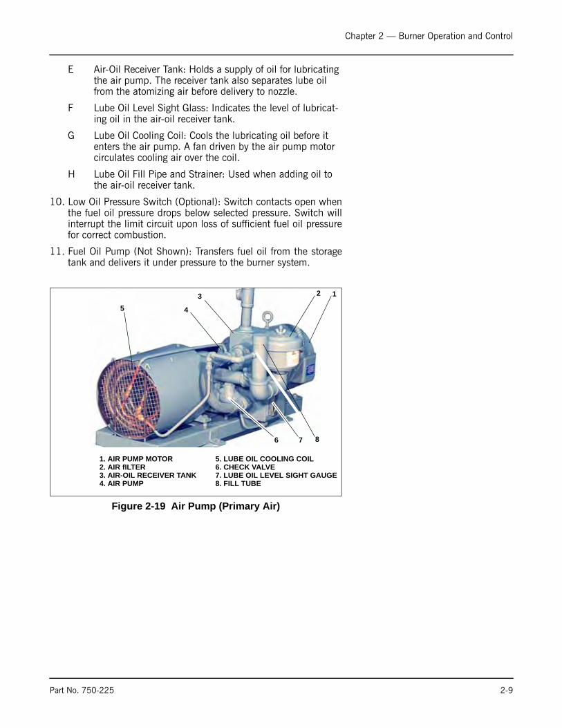
E Air-Oil Receiver Tank: Holds a supply of oil for lubricating the air pump. The receiver tank also separates lube oil from the atomizing air before delivery to nozzle.
F Lube Oil Level Sight Glass: Indicates the level of lubricat-ing oil in the air-oil receiver tank.
G Lube Oil Cooling Coil: Cools the lubricating oil before it enters the air pump. A fan driven by the air pump motor circulates cooling air over the coil.
H Lube Oil Fill Pipe and Strainer: Used when adding oil to the air-oil receiver tank.
10. Low Oil Pressure Switch (Optional): Switch contacts open whenthe fuel oil pressure drops below selected pressure. Switch willinterrupt the limit circuit upon loss of sufficient fuel oil pressurefor correct combustion.
11. Fuel Oil Pump (Not Shown): Transfers fuel oil from the storagetank and delivers it under pressure to the burner system.
Figure 2-19 Air Pump (Primary Air)
876
5 4
3 2 1
1. AIR PUMP MOTOR2. AIR fILTER3. AIR-OIL RECEIVER TANK4. AIR PUMP
5. LUBE OIL COOLING COIL6. CHECK VALVE7. LUBE OIL LEVEL SIGHT GAUGE8. FILL TUBE
Part No. 750-225 2-9

Chapter 2 — Burner Operation and Control
F. ADDITIONAL CONTROLS FOR HEAVY OILThe oil heater (Figure 2-20 Steam) is provided to heat heavy oil tothe point where it can be effectively atomized and burned. Mostheavy oil heaters utilize an electric heater to reduce the viscosity ofthe heavy oil until the point where either steam or hot water isavailable. Heavy oil heaters operating with hot water will haveadditional controls not represented in Figure 2-20.
Heater Switch (Not Shown): Manually provides power to the oilheater system.
1. Oil Heater (Electric): Used for heating sufficient fuel oil for low-fire flow during cold starts before steam or hot water is availablefor heating. The heater must be turned off during extendedboiler lay-up, or at any time the fuel oil transfer pump isstopped.
2. Electric Oil Heater Thermostat: Senses fuel oil temperature andenergizes or deenergizes the electric oil heater to maintainrequired temperature of the fuel oil.
3. Steam Oil Heater Thermostat: Senses fuel oil temperature andcontrols the opening and closing of the steam heater valve tomaintain the required temperature of the fuel oil.
Figure 2-20 Oil Heating Assembly (Steam)
1. OIL HEATER (ELECTRIC)2. OIL HEATER THERMOSTAT (STEAM)3. OIL HEATER THERMOSTAT (ELECTRIC)4. OIL HEATER SHELL5. OIL RETURN TO TANK6. OIL INLET FROM TANK7. CHECK VALVE8. STEAM TRAP9. CHECK VALVE
10. STEAM HEATER PRESSURE REGULATOR11. STEAM HEATER SOLENOID VALVE12. STEAM PRESSURE GAUGE13. OIL RELIEF VALVE14. LOW OIL TEMPERATURE SWITCH15. OIL SUPPLY PRESSURE GAUGE16. OIL RETURNED FROM FUEL OIL CONTROLLER17. HEATED OIL TO BURNER18. FUEL OIL STRAINER
1 2 4 576 8
9
10
11121314
3
15
18
2-10
Part No. 750-225
Chapter 2 — Burner Operation and Control
4. Oil Heater Shell (Steam/Hot Water): Heats fuel oil throughmedium of steam or hot water. Electric heater is housed in thesteam heater, but is housed separately on a hot water heater.Steam oil heaters on 15 psi boilers operate at boiler pressure.Steam oil heaters furnished on high pressure boilers are to beoperated at less than 15 psi. Operation is accomplished with asteam pressure regulator valve.
5. Oil Return To Tank: Excess oil returned to the heavy oils supplytank.
6. Oil Inlet From Supply Tank: Heavy oil inlet from the supply tank.
7. Steam Heater Check Valve: Prevents oil contamination of thewaterside of pressure vessel should any leakage occur in the oilheater.
8. Steam Trap: Drains condensate and prevents loss of steam fromthe steam oil heater. Condensate must be piped to a safe pointof discharge.
9. Check Valve (Steam Heater Discharge): Prevents air entryduring shutdown periods when cooling action may createvacuum within steam heater.
10. Steam Heater Pressure Regulator: Adjust to provide reduced(usually less than 15 psi) steam pressure to the heater toproperly maintain the required fuel oil temperature. Theregulator and the pressure gauge are not furnished on 15 psiunits.
11. Steam Heater Solenoid Valve: A normally open solenoid valveopened by the steam oil heater thermostat to allow flow ofsteam to the steam heater to maintain temperature of fuel oil.
12. Steam Pressure Gauge: Indicates steam pressure entering theheater.
13. Oil Relief Valve: Allows release of excessive pressure to thereturn side of the oil line piped to the tank.
14. Low-Oil-Temperature Switch: Thermostatic switch that preventsburner from starting, or stops burner firing if fuel oil temperatureis lower than required for oil burner operation.
15. Oil Supply Pressure Gauge: Indicates fuel oil pressure in the oilheater and supply pressure to the fuel oil controller’s pressureregulator.
In addition to the components of the fuel oil controller mentioned in Section E, the following are used with a heavy oil fired burner.
A High-Oil-Temperature Switch (Optional): Switch contacts open when fuel oil temperature raises above a selected temperature. Switch will interrupt the limit circuit in the event fuel oil temperature rises above the selected point.
Part No. 750-225 2-11

Chapter 2 — Burner Operation and Control
B Hot Water Oil Heater Thermostat: Used on a hot water boiler to sense fuel oil temperature and control the starting and stopping of the booster water pump.
C Booster Water Pump: Started and stopped by the hot water thermostat to regulate the flow of hot water through the hot water oil heater to maintain temperature of fuel oil.
D Fuel Oil Thermometer: Indicates temperature of fuel oil being supplied to the fuel oil controller.
E Back Pressure Valve: For adjustment of oil pressure on the downstream side of the metering valve. Also regulates rate of return oil flow.
F Oil Return Pressure Gauge: Indicates oil pressure on the return side of the fuel oil controller.
G Manual By-Pass Valve: Provided as a time saver in estab-lishing oil flow. When open, it permits circulation of oil through the supply and return lines. The valve must be closed prior to initial light off.
H Orifice Oil Control Valve: Valve may be opened prior to start-up to aid in establishing fuel oil flow through the controller. The valve must be closed prior to initial light off. Its disc has an orifice to permit a continuous circula-tion of hot fuel oil through the controller.
I Air Purge Valve: Solenoid valve opens simultaneously with closing of oil solenoid valve at burner shutdown, allowing compressed air to purge oil from the burner nozzle and adjacent piping. The oil is burned by the diminishing flame, which continues burning for approximately 4 sec-onds after the oil solenoid valve closes.
J Air Purge Orifice Nozzle: Limits purging air to proper quantity for expelling unburned oil at normal delivery rate.
K Air Purge Orifice Nozzle Filter: Filters the purging air of any particles that might plug the air purge orifice nozzle.
L Air Purge Check Valve: Valve check prevents fuel oil from entering the atomizing air line.
M Air Purge Relay: When energized, controls operation of air purge valve.
G. CONTROLS FOR COMBINATION BURNERS ONLY
(1) Gas-Oil Switch (Figure 2-21): Burners equipped to burn eitheroil or gas include equipment for each fuel. The selector switchengages the appropriate interlocks and controls for gas or oiloperation. Chapter 4 details the required mechanical functions ofeach fuel system.
2-12 Part No. 750-225
Chapter 2 — Burner Operation and Control
H. COMBUSTION AIRAir for combustion of fuel (often referred to as “secondary” air) isfurnished by the forced draft fan (Figure 2-23) mounted in the boilerhead. In operation, air pressure is built up in the entire head and isforced through a diffuser plate for a thorough mixture with the fuelfor proper combustion. The supply of secondary air to the burner isgoverned by automatically throttling the output of the fan byregulating the rotary air damper. The damper provides the properamount of air for correct ratio of air to fuel for efficient combustionat all firing rates.
I. AUTOMATIC IGNITIONOil or gas burners are ignited by an interrupted-type pilot. The pilotflame is ignited automatically by an electric spark.
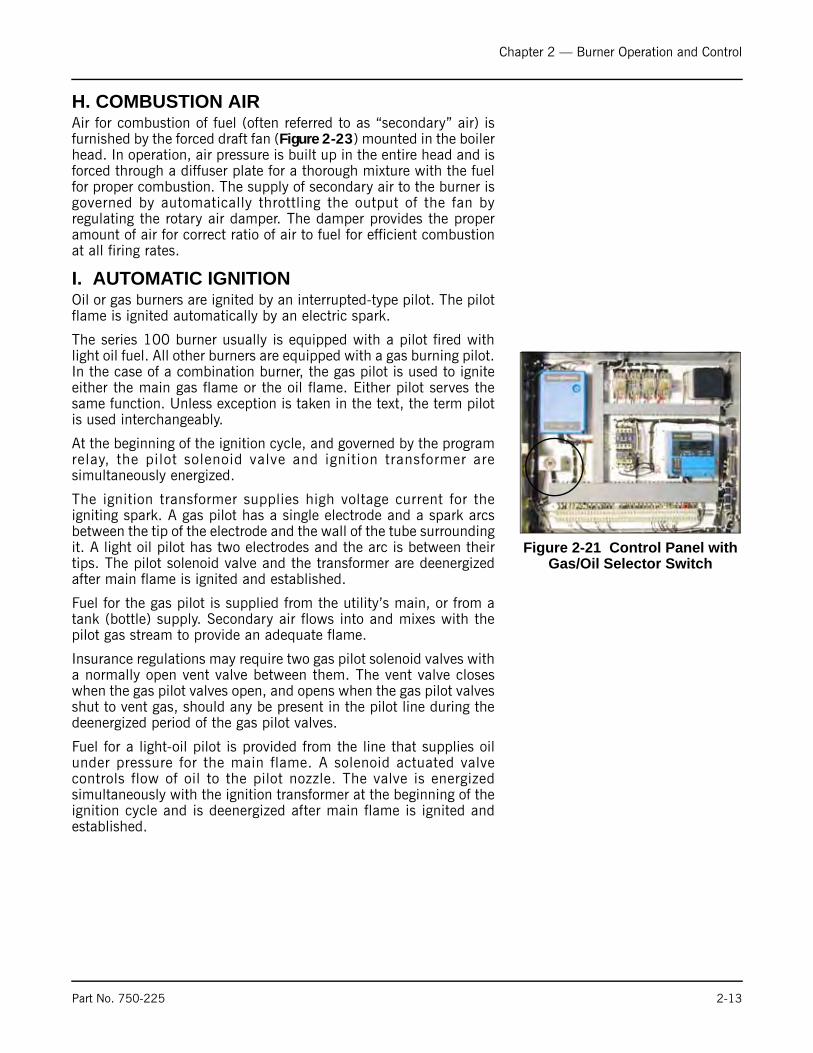
The series 100 burner usually is equipped with a pilot fired withlight oil fuel. All other burners are equipped with a gas burning pilot.In the case of a combination burner, the gas pilot is used to igniteeither the main gas flame or the oil flame. Either pilot serves thesame function. Unless exception is taken in the text, the term pilotis used interchangeably.
At the beginning of the ignition cycle, and governed by the programrelay, the pilot solenoid valve and ignition transformer aresimultaneously energized.
The ignition transformer supplies high voltage current for theigniting spark. A gas pilot has a single electrode and a spark arcsbetween the tip of the electrode and the wall of the tube surroundingit. A light oil pilot has two electrodes and the arc is between theirtips. The pilot solenoid valve and the transformer are deenergizedafter main flame is ignited and established.
Fuel for the gas pilot is supplied from the utility’s main, or from atank (bottle) supply. Secondary air flows into and mixes with thepilot gas stream to provide an adequate flame.
Insurance regulations may require two gas pilot solenoid valves witha normally open vent valve between them. The vent valve closeswhen the gas pilot valves open, and opens when the gas pilot valvesshut to vent gas, should any be present in the pilot line during thedeenergized period of the gas pilot valves.
Fuel for a light-oil pilot is provided from the line that supplies oilunder pressure for the main flame. A solenoid actuated valvecontrols flow of oil to the pilot nozzle. The valve is energizedsimultaneously with the ignition transformer at the beginning of theignition cycle and is deenergized after main flame is ignited andestablished.
Figure 2-21 Control Panel with Gas/Oil Selector Switch
Part No. 750-225 2-13

Chapter 2 — Burner Operation and Control
J. ATOMIZING AIRAir for atomizing the fuel oil (often referred to as “primary air”) ispumped by the air pump into the air-oil receiver tank and deliveredunder pressure through a manifold block to the oil burner nozzle.
The atomizing air mixes with the fuel oil just prior to the oil leavingthe nozzle.
Atomizing air pressure is indicated by the air pressure gauge on theburner gun.
Air pressure from the pump also forces sufficient oil from the tankto the pump bearings to lubricate them and also to provide a sealand lubrication for the pump vanes. As a result, the air delivered tothe tank contains some lube oil; however, most of it is recoveredthrough baffles and filters in the tank before the air passes to theburner.
Some of the primary air is also used to assist the oil pressureregulators of the fuel oil controller. Further explanation is given inchapter 5.
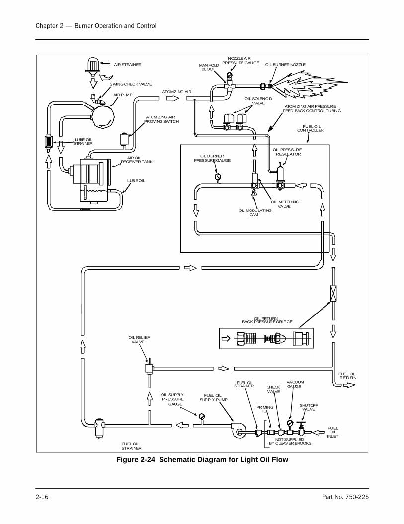
K. OIL FUEL FLOW - LIGHT OILThe oil fuel flow system schematic is shown in Figure 2-24. Oil flowis indicated by arrows and the pertinent controls are called out. Fueloil is delivered into the system by a supply pump which delivers partof its discharge to the oil burner. Excess oil is returned to the oilstorage tank through the fuel oil relief valve and oil return line.Normally the pump operates only while the burner is in operation,although a positioning switch is often provided so that eithercontinuous or automatic pump operation can be obtained.
The oil flows through a fuel oil strainer to prevent any foreignmaterial from flowing through the control valves and nozzle. Thefuel oil controller contains in a single unit, a metering valve, aregulator, and a gauge required to regulate the pressure and flow ofoil to the burner. The adjustable regulator controls the pressure. Toassist in the regulation, back pressure is created by an orifice nozzlelocated in the oil return line immediately downstream of the fuel oilcontroller.
Figure 2-22 Air-Oil Receiver Tank
AIR AND OILMIXTURE FROM
PUMPAIR TO NOZZLE
STEEL WOOLPADS (3)
(COARSE GRADE)
O-RING GASKET
SEPARATED OILLUBE OIL
LUBE OILTO COOLING COIL
AND PUMP
Figure 2-23 Secondary Air Flow Diagram
Cleaver Brooks
FIRING HEAD
STABILIZERROTARY
AIR DAMPER
GAS PILOTASSEMBLY
FORCEDDRAFT FAN
FAN MOTOR
INTAKE
NOTICE: FAN ROTATION ISCOUNTERCLOCKWISEWHEN VIEWED FROM
FRONT OF BOILER.
2-14 Part No. 750-225
Chapter 2 — Burner Operation and Control
The programming relay energizes or deenergizes the solenoid oilvalves to permit or cut off oil flow to the burner. Two valves,operating simultaneously, are used. The valves are closed whendeenergized. They cannot be opened (energized) unless thecombustion air proving switch and the atomizing air proving switchare closed. The two switches are satisfied, respectively, by sufficientcombustion air pressure from the forced draft fan and pressurizedair from the air pump.
The oil flow to the burner is controlled by the movement of themetering stem in the oil metering valve, which varies the flow tomeet load demands. The metering valve and the air damper arecontrolled simultaneously at all times by the modulating motor toproportion combustion air and fuel for changes in load demand.
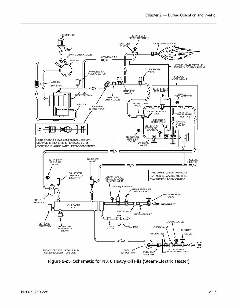
L. OIL FUEL FLOW - HEAVY OILThe oil fuel flow and circulating system is shown in schematicdiagram form in Figure 2-25. The pertinent controls are called outand the oil flow is indicated by arrows.
Fuel oil is delivered into the system by the fuel oil supply pumpwhich delivers part of its discharge to the oil heater. The remainderof the fuel oil returns to the oil storage tank through a fuel oil reliefvalve and oil return line.
The combination electric and steam oil preheater is controlled bythermostats. The electric oil heater thermostat energizes the electricheater, which is provided to supply heated oil on cold starts. Thesteam heater thermostat controls operation of the steam solenoidvalve to permit a flow of steam to the heater when steam isavailable.
A hot water boiler is equipped to heat the oil with hot water fromthe boiler, unless other preheating equipment is utilized. Theelectric heater, which is housed separately, is sized to provideheated oil on a cold start. The hot water thermostat controls the
Part No. 750-225 2-15
Chapter 2 — Burner Operation and Control
Figure 2-24 Schematic Diagram for Light Oil Flow
FUEL OILSTRAINER
OIL SUPPLYPRESSURE
GAUGE
OIL RELIEFVALVE
FUEL OILSUPPLY PUMP
FUEL OILSTRAINER
NOT SUPPLIEDBY CLEAVER BROOKS
TEE
VALVEGAUGE
SHUTOFFVALVE
REGULATOROIL PRESSURE
OIL MODULATINGCAM
PRESSURE GAUGEOIL BURNER
CONTROLLERFUEL OIL
VALVEOIL SOLENOID
BACK PRESSURE ORIFICEOIL RETURN
RECEIVER TANKAIR OIL
LUBE OIL
PROVING SWITCHATOMIZING AIR
LUBE OILSTRAINER
SWING CHECK VALVE
AIR STRAINER
ATOMIZING AIR
MANIFOLDBLOCK
PRESSURE GAUGENOZZLE AIR
OIL BURNER NOZZLE
INLETOIL
FUEL
AIR PUMP
RETURNFUEL OIL
VACUUMCHECK
PRIMING
VALVEOIL METERING
ATOMIZING AIR PRESSUREFEED BACK CONTROL TUBING
2-16 Part No. 750-225
Chapter 2 — Burner Operation and Control
Figure 2-25 Schematic for N0. 6 Heavy Oil Fils (Steam-Electric Heater)
OIL HEATER(ELECTRIC) OIL HEATER
THERMOSTAT(STEAM)
OIL HEATERSHELL
FUEL OILSTRAINER
OIL SUPPLYPRESSURE
GAUGE
OIL HEATERTHERMOSTAT(ELECTRIC)
OIL RELIEFVALVE
STEAM HEATERPRESSURE GAUGE
STEAM HEATER
SOLENOID VALVESTEAM PRESSURE
REGULATOR
CHECK VALVESTEAM STRAINER
STEAM SHUTOFFVALVE
CHECKVALVE STEAM TRAP
FUEL OILSUPPLY PUMP FUEL OIL
STRAINER
NOT SUPPLIEDBY CLEAVER BROOKS
PRIMING TEE
CHECK VALVE
VACUUM GAUGE
SHUTOFF
VALVE
NOTE: CONDENSATE FROM STEAMTRAP MUST BE WASTED AND PIPEDTO A SAFE POINT OF DISCHARGE.
CORRESPONDING HOT WATER HEATING COMPONENTS.STEAM GENERATORS. REFER TO FIGURE 1-2 FORNOTE: DIAGRAM SHOWS COMPONENTS USED WITH
BY-PASSMANUAL
VALVE
FUEL OILTHERMOMETER
REGULATOROIL PRESSURE
OIL MODULATINGCAM
PRESSURERELIEF VALVE
OIL RETURNPRESSURE
GAUGE
ORIFICEDVALVE
OIL BURNERPRESSURE
GAUGE
VALVEOIL METERING
SWITCHTEMPERATURE
LOW OIL
CONTROLLERFUEL OIL
VALVEOIL SOLENOID
VALVEAIR PURGE
CHECK VALVEAIR PURGE
CHECK VALVEAIR PURGE
RECEIVER TANKAIR OIL
LUBE OIL
PROVING SWITCHATOMIZING AIR
LUBE OIL
STRAINER
SWING CHECK VALVE
AIR STRAINER
ATOMIZING AIR
MANIFOLDBLOCK
PRESSURE GAUGENOZZLE AIR
OIL BURNER NOZZLE
* THESE ITEMS ARE USED ON HIGHPRESSURE GENERATORS ONLY
INLETOIL
FUEL
AIR PUMP
RETURNFUEL OIL
STEAM INLET
ATOMIZING AIR PRESSUREFEEDBACK CONTROL TUBING
Part No. 750-225 2-17

Chapter 2 — Burner Operation and Control
operation of a pump that supplies hot water to the oil heater whenhot water is available.
The heated oil flows through a fuel oil strainer to prevent any foreignmatter from entering the control valves and nozzle.
The fuel oil controller contains, in a single unit, the necessaryvalves, regulators and gauges to regulate the pressure and flow ofoil to the burner.
The program relay energizes or deenergizes the solenoid oil valve topermit or cut off oil flow to the burner. The oil solenoid is closedwhen deenergized. It cannot be opened (energized) unless thecombustion air proving switch, the atomizing air proving switch,and the low oil-temperature and any pressure switches are closed.They are satisfied, respectively, by sufficient combustion airpressure from the forced draft fan, pressurized air from the air pumpand sufficient oil temperature and pressure.
Oil flow to the burner is controlled by the movement of the meteringstem of the oil metering valve, which varies the flow to meet loaddemands. The metering valve and the air damper are controlledsimultaneously at all times by the modulating motor to proportioncombustion air and fuel for changes in load demand.
Oil is purged from the burner gun upon each burner shutdown. Theair purge solenoid valve opens as the fuel valve closes, divertingatomizing air through the oil line. The air assures a clean nozzle andline for subsequent restart.
M. GAS FUEL FLOWMetered gas from the utility flows through the pressure regulator ata reduced pressure suitable to burner requirements, through themain gas shutoff cock, main gas valve(s), and modulating butterflygas valve to the non- premix orifice-type burner.
The main gas valve is of the normally closed type, and is opened(energized) in proper sequence by the programming relay.
The butterfly gas valve modulates the flow of gas from low throughhigh fire settings. The position of the butterfly valve disc is governedby the gas modulating cam. The butterfly gas valve, and the aircontrol damper are controlled simultaneously by the modulatingmotor to proportion combustion air and fuel for changes in loaddemand.
The gas flow rate required for rated burner input depends upon theheating valve (Btu/cubic foot) of the gas supplied. The gas pressureregulator adjusts the gas pressure (flow rate) to the entrance of thegas train. The regulator is not always supplied with the burner, butmay be provided by others.
The main gas valves cannot be energized (opened) unless thecombustion air proving switch is closed to indicate a sufficientsupply of combustion air. The low gas pressure and high gaspressure switches must be closed to prove sufficient, but notexcessive, gas fuel pressure.
Figure 2-26 Main Gas Train
2-18 Part No. 750-225
Chapter 2 — Burner Operation and Control
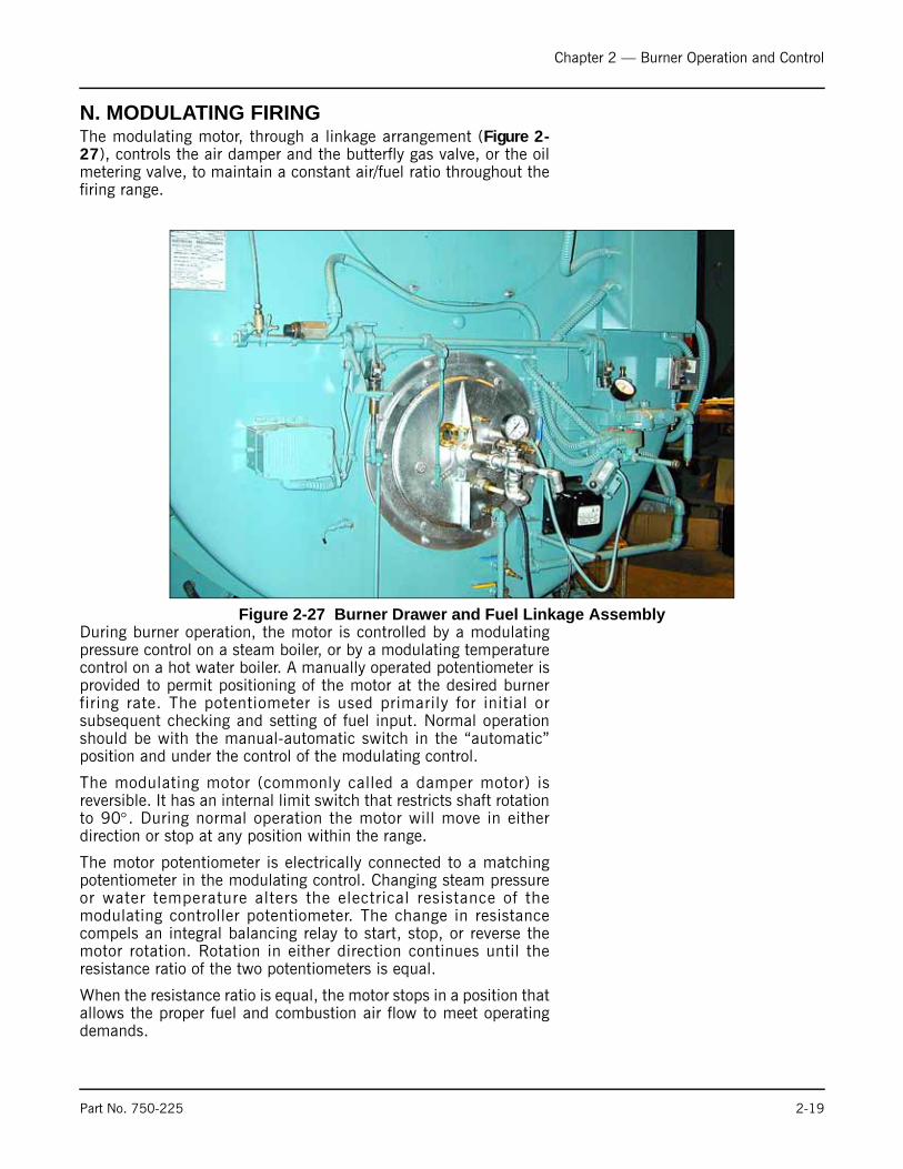
N. MODULATING FIRINGThe modulating motor, through a linkage arrangement (Figure 2-27), controls the air damper and the butterfly gas valve, or the oilmetering valve, to maintain a constant air/fuel ratio throughout thefiring range.
During burner operation, the motor is controlled by a modulatingpressure control on a steam boiler, or by a modulating temperaturecontrol on a hot water boiler. A manually operated potentiometer isprovided to permit positioning of the motor at the desired burnerfiring rate. The potentiometer is used primarily for initial orsubsequent checking and setting of fuel input. Normal operationshould be with the manual-automatic switch in the “automatic”position and under the control of the modulating control.
The modulating motor (commonly called a damper motor) isreversible. It has an internal limit switch that restricts shaft rotationto 90°. During normal operation the motor will move in eitherdirection or stop at any position within the range.
The motor potentiometer is electrically connected to a matchingpotentiometer in the modulating control. Changing steam pressureor water temperature alters the electrical resistance of themodulating controller potentiometer. The change in resistancecompels an integral balancing relay to start, stop, or reverse themotor rotation. Rotation in either direction continues until theresistance ratio of the two potentiometers is equal.
When the resistance ratio is equal, the motor stops in a position thatallows the proper fuel and combustion air flow to meet operatingdemands.
Figure 2-27 Burner Drawer and Fuel Linkage Assembly
Part No. 750-225 2-19

Chapter 2 — Burner Operation and Control
A feature designed into the circuitry maintains the modulating motorin the low-fire position during ignition and keeps it there until themain flame is established. A low-fire switch, integral to the motor,is actuated by the rotation of the motor. The switch must be closedto establish that the damper and fuel metering valves are in the low-fire position before the programmer commences into the ignitionperiod. During this time, neither the manual flame control nor themodulating control have any control over the damper motor,regardless of their setting.
An optionally equipped boiler uses a second integral switch toestablish that the motor has driven the damper to an open positionduring the pre-purge period. The second integral switch closes, ashigh fire position is approached, to complete an internal circuit inthe programmer to allow continuation of the programming cycle.
2-20 Part No. 750-225
Milwaukee, Wisconsin
www.cleaver-brooks.com
Chapter 3Waterside Care and Requirements
ContentsA. GENERAL . . . . . . . . . . . . . . . . . . . . . . . . . . . . . . . . . . . . . . 3-3B. WATER REQUIREMENTS . . . . . . . . . . . . . . . . . . . . . . . . . . . 3-3C. WATER TREATMENT . . . . . . . . . . . . . . . . . . . . . . . . . . . . . . 3-8D.CLEANING . . . . . . . . . . . . . . . . . . . . . . . . . . . . . . . . . . . . . . 3-8E. BOIL-OUT OF A NEW UNIT . . . . . . . . . . . . . . . . . . . . . . . . . . 3-9F. WASHING OUT . . . . . . . . . . . . . . . . . . . . . . . . . . . . . . . . . . 3-11G. BLOWDOWN STEAM BOILER . . . . . . . . . . . . . . . . . . . . . . . 3-12H. PERIODIC INSPECTION . . . . . . . . . . . . . . . . . . . . . . . . . . . 3-15I. PREPARATION FOR EXTENDED LAY-UP . . . . . . . . . . . . . . . . 3-16

Chapter 3 — Waterside Care and Requirements
A.GENERALThe operator should be familiar with Chapter 3 before attempting toplace the unit into operation.
Although it is of prime importance, the subject of water supply andtreatment cannot adequately be covered in this manual. For specificinformation or assistance with your water treatment requirements,contact your Cleaver-Brooks service and parts representative.
Feedwater equipment should be checked and ready for use. Be surethat all valves, piping, boiler feed pumps, and receivers are installedin accordance with prevailing codes and practices.
Water requirements for both steam and hot water boilers areessential to boiler life and length of service. It is vital care be takenin placing the pressure vessel into initial service. The waterside ofnew boilers and new or remodeled steam or hot water systems maycontain oil, grease or other foreign matter. A method of boiling outthe vessel to remove the accumulations is described later in Chapter3.
Boilers, as a part of a hot water system, require proper watercirculation. The system must be operated as intended by itsdesigner in order to avoid thermal shock or severe, possiblydamaging, stresses from occurring to the pressure vessel.
B. WATER REQUIREMENTS
1. HOT WATER BOILER
Air Removal
The hot water outlet includes a dip tube which extends 2 to 3 inchesinto the boiler. The dip tube reduces the possibility of air, whichmay be trapped at the top of the shell, from entering into thesystem. Oxygen or air released in the boiler will collect or be trappedat the top of the boiler shell.
The air vent tapping on the top center line of the boiler should bepiped into the expansion or compression tank. Air trapped at the topof the boiler will find its way out of the boiler through the tapping.
Minimum Water Temperature - The minimum recommended boilerwater temperature is 170°F. When water temperatures lower than170°F are used, the combustion gases are reduced in temperatureto a point where water vapor condenses, causing corrosion in theboiler and possible breeching.
Condensation is more severe on a unit that operates intermittentlyand which is greatly oversized for the actual load. Condensation canbe minimized by maintaining boiler water temperatures above170°F.
A temperature of 170°F is also recommended in order to provide asufficient “temperature head” when No. 6 fuel oil is to be heated tothe proper atomizing temperature by the boiler water in a safety-type oil preheater. (The electric preheater on the boiler must provide
NoticeThis manual only covers boilersusing water. Glycol solutionshave d i f f e ren t opera t ingrequirements, circulation ratesand temperatures, etc.
3-2 Part No. 750-225

Chapter 3 — Waterside Care and Requirements
additional heat to the oil if boiler water temperature is notmaintained above 200°F.)
Rapid Replacement of Boiler Water - The system layout andcontrols should be arranged to prevent the possibility of pumpinglarge quantities of cold water into a hot boiler, which will causeshock or thermal stresses. Water temperature in a boiler of 200°For 240°F cannot be completely replaced with 80°F water in a fewminutes time without causing thermal stress. The same fact appliesto periods of normal operation, as well as during initial start-up.
The circulating pumps should be interlocked with the burner so thatthe burner cannot operate unless the circulating pump is running inorder to avoid damage to the equipment.
When indiv idual zone ci rculat ing pumps are used, i t isrecommended that they be kept running-even though the heat usersdo not require hot water. The relief device or by-pass valve will thusallow continuous circulation through the boiler and can help preventrapid replacement of boiler water with cold zone water.
Continuous Flow Through the Boiler - The system should be pipedand the controls arranged to allow water circulation through theboiler under all operating conditions. The operation of three-wayvalves and system controls should be checked to be sure that theboiler will not be by-passed. Constant circulation through the boilereliminates the possibility of stratification within the unit and resultsin more even water temperatures to the system.
A rule of thumb of 3/4 to 1 gpm per boiler horsepower can be usedto determine the minimum continuous flow rate through the boilerunder all operating conditions. The operator should determine thata flow of water exists through the boiler before initial firing or refiringafter boiler has been drained.
Water Circulation
The chart in Table 3-1: shows the maximum gpm circulation rate ofboiler water in relation to full boiler output and system temperaturedrop.
Multiple Boiler Installations - When multiple boilers are used, caremust be taken to ensure adequate or proportional flow through theboilers. Proportional flow can best be accomplished by use ofbalancing valves and gauges in the supply line from each boiler. Ifbalancing valves or orifice plates are used, a significant pressuredrop (e.g., 3-5 psi) must be taken across the balancing device toaccomplish the purpose.
If care is not taken to ensure adequate or proportional flow throughthe boilers, wide variations in firing rates between the boilers canresult.
In extreme cases, one boiler may be in the high-fire position whilethe other boiler or boilers may be at low fire. The net result wouldbe that the common header water temperature to the system wouldnot be up to the desired point.
NoticeI f the ope ra t ing wate rtemperature going to the systemmust be lower than 170°F, theopera t ing bo i le r wate rtempera tu re shou ld be aminimum of 170°F (200°F ifused to preheat No. 6 oil) andmixing valves should be used toavoid damage to the equipment.
Part No. 750-225 3-3
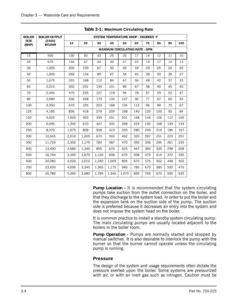
Chapter 3 — Waterside Care and Requirements
Table 3-1: Maximum Circulating Rate
Pump Location - It is recommended that the system circulatingpumps take suction from the outlet connection on the boiler, andthat they discharge to the system load. In order to put the boiler andthe expansion tank on the suction side of the pump. The suctionside is preferred because it decreases air entry into the system anddoes not impose the system head on the boiler.
It is common practice to install a standby system circulating pump.The main circulating pumps are usually located adjacent to theboilers in the boiler room.
Pump Operation - Pumps are normally started and stopped bymanual switches. It is also desirable to interlock the pump with theburner so that the burner cannot operate unless the circulatingpump is running.
Pressure
The design of the system and usage requirements often dictate thepressure exerted upon the boiler. Some systems are pressurizedwith air, or with an inert gas such as nitrogen. Caution must be
BOILER SIZE (BHP)
BOILER OUTPUT (1000) BTU/HR
SYSTEM TEMPERATURE DROP - DEGREES °F
10 20 30 40 50 60 70 80 90 100
MAXIMUM CIRCULATING RATE - GPM
15 500 100 50 33 25 20 17 14 12 11 10
20 670 134 67 45 33 27 22 19 17 15 13
30 1,005 200 100 67 50 40 33 29 25 22 20
40 1,340 268 134 89 67 54 45 38 33 30 27
50 1,675 335 168 112 84 67 56 48 42 37 33
60 2,010 402 201 134 101 80 67 58 50 45 40
70 2,345 470 235 157 118 94 78 67 59 52 47
80 2,680 536 268 179 134 107 90 77 67 60 54
100 3,350 670 335 223 168 134 112 96 84 75 67
125 4,185 836 418 279 209 168 140 120 105 93 84
150 5,025 1,005 503 335 251 201 168 144 126 112 100
200 6,695 1,340 670 447 335 268 224 192 168 149 134
250 8,370 1,675 838 558 419 335 280 240 210 186 167
300 10,045 2,010 1,005 670 503 402 335 287 251 223 201
350 11,720 2,350 1,175 784 587 470 392 336 294 261 235
400 13,400 2,680 1,340 895 670 535 447 383 335 298 268
500 16,740 3,350 1,675 1,120 838 670 558 479 419 372 335
600 20,080 4,020 2,010 1,340 1,005 805 670 575 502 448 402
700 23,430 4,690 2,345 1,565 1,175 940 785 670 585 520 470
800 26,780 5,360 2,680 1,785 1,340 1,075 895 765 670 595 535
3-4 Part No. 750-225

Chapter 3 — Waterside Care and Requirements
exercised to ensure that the proper relationship of pressure-to-temperature exists within the boiler so that all of the boiler’s internalsurfaces are fully wetted at all times. For this reason, the internalboiler pressure, as indicated on the water pressure gauge, must beheld to the level shown in Figure 3-1.
When initially firing a newly installed boiler, or when cutting anexisting boiler into an operating system, the boiler or boilers to becut into operation MUST be pressurized equal to the system and/orother boilers prior to opening the header valves.
It is advisable to have a thermometer installed in the return line toindicate return water temperature. Knowing the supply watertemperature, the boiler system differential can be established. Withknowledge of the pumping rate, the operator can easily detect anyexcessive load condition and take appropriate corrective action.
Special caution must be taken to guard against any condition, orcombination of conditions, that might lead to the transfer of coldwater to a hot boiler or hot water to a cold boiler. It cannot be over-emphasized that rapid changes in temperature within the boilercan, and sometimes do, cause damage.
Figure 3-1 Internal Boiler Pressure
Part No. 750-225 3-5

Chapter 3 — Waterside Care and Requirements
2. STEAM BOILER
Feed Pump Operation
BEFORE turning on the pump motor be certain that all valves in thewater feed line are open to prevent possible damage to the feedpump mechanism. After opening the valves, momentarily energizethe feed pump motor to establish correct pump rotation. With thecorrect rotation established, close the boiler feed pump entranceswitch. The pump should shut down when the water level reachesthe proper level shown in Figure 3-2.
Feedwater pumps must have adequate capacity to maintainrequired water level under all operating conditions. Check thefeedwater pumps periodically and maintain as necessary to preventunexpected breakdowns.
Water Feeder (optional) Operation
Water feeder operation is usually applicable to boilers operating at15 psi steam or less. It is only necessary to open the water supplyline valve and the water feeder discharge valve.
Figure 3-2 Low Water Cut Off Sight Gauge
A. NORMAL LEVEL OF WATER: FEED PUMP TURNS OFF AT THIS POINT. FILL PRESSURE VESSEL INI-TIALLY TO THIS HEIGHT.
B. PUMP TURNS ON WHEN WATER LEVEL REACHES B. DISTANCE A-B IS APPROXIMATELY3/4 INCH.
C. LOW WATER CUT-OFF POINT BURNER WILL SHUT OFF IF WATER LEVEL LOWERS TO THIS P[OINT.
D. FIRST VISIBLE POINT IN THE GAUGE GLASS.
TYPICAL LOW WATERCUT-OFF AND PUMP
CONTROL
ABCD
NoticePrior to operating the pump,carefully check the alignment ofthe flexible coupling, if one isused. A properly aligned couplingwill last a long time and providet roub le - f ree mechan ica loperation.
! WarningThe isolation valves and the water column piping must belocked open during operation. Failure to do so may result ina low water condition. Failure to follow these instructionscould result in serious personal injury or death
3-6 Part No. 750-225
Chapter 3 — Waterside Care and Requirements
C. WATER TREATMENTProperly treated boiler feed water, coupled with good engineeringand operating practices, lead to maximum effectiveness and longtrouble-free life of pressure vessels, at the lowest operating cost.Contact your local Cleaver-Brooks authorized representative forinformation on how to prevent the presence of unwanted solids andcorrosive gases.
Objectives of water treatment in general are:
• Prevent hard scale deposits or soft sludge deposits, which reduce heat transfer and can lead to overheated metal and costly downtime and repairs.
• Eliminate corrosive gases in the supply or boiler water.
• Prevent intercrystalline cracking or caustic embrittlement of boiler metal.
• Prevent carryover and foaming.
Accomplishment of the above objectives generally requires properfeedwater treatment before and after introduction of the water intothe boiler. The selection of pre-treatment processes depends uponthe water source, its chemical characteristics, amount of makeupwater needed, plant operating practices, etc. Treating methodsinclude filtering, softening, de-mineralizing, deaerating, andpreheating. After-treatment involves chemical treatment of theboiler water.
Because of the variables involved, no single boiler compound canbe considered a “cure-all” nor is it advisable to experiment withhomemade treating methods. Sound recommendations and theiremployment should be augmented by a periodic analysis of thefeedwater, boiler water, and condensate.
The internal or waterside surfaces of the pressure vessel should beinspected with enough frequency to determine the presence of anycontamination, accumulations of foreign matter, or corrosion, and/or pitting. If any of the conditions are detected, contact your localCleaver-Brooks authorized representative for advice on correctiveaction.
A properly sized water meter should be installed in the raw watermake-up line in order to accurately determine the amount of rawwater admitted to the boiler (steam or hot water) and to aid inmaintaining proper waterside conditions.
D. CLEANING
1. HOT WATER AND STEAM PIPINGSteam and water piping systems connected to the boiler maycontain oil, grease, or foreign matter. The impurities must beremoved in order to prevent damage to pressure vessel heatingsurfaces. On a steam system, the condensate should be wasteduntil tests show the elimination of undesirable impurities. Duringthe period that condensate is wasted, attention must be given to thetreatment of the raw water used as make-up so that an
NoticeIn the event that water columnisolation valves are provided orinstalled, it must be establishedthat the valves are open andseated or locked in the openpos i t ion. I f the va lves areinstalled, it is illegal to operatethe bo i l e r w i th c losed o runsealed open valves.
Part No. 750-225 3-7
Chapter 3 — Waterside Care and Requirements
accumulation of unwanted materials or corrosion does not occur.For more information, contact your local Cleaver-Brooks authorizedrepresentative.
On a hot water system, chemical cleaning is generally necessaryand the entire system should be drained after treatment. Consultyour local Cleaver-Brooks author ized representat ive forrecommendations, cleaning compounds, and applicationprocedures.
2. PRESSURE VESSELThe waterside of the pressure vessel must be kept clean fromgrease, sludge, and foreign material. Such deposits, if present, willshorten the life of the pressure vessel, will interfere with efficientoperation and functioning of control of safety devices, and quitepossibly cause unnecessary and expensive re-work, repairs, anddown-time.
The installation and operating conditions that the boiler will besubjected to should be considered and cleaning of the waterside ofthe pressure vessel should be provided during the course of initialstart-up.
The pressure vessel and the steam and return lines or hot waterpiping represent, in effect, a closed system. Although the steam andreturn (condensate) lines or the hot water piping system may havebeen previously cleaned, it is possible that:
• Cleaning has been inadequate.
• Partial or total old system is involved.
• Conditions may prevent adequate cleaning of piping.
The pressure vessel waterside should be inspected on a periodicbasis. An inspection will reveal true internal conditions and serve asa check against conditions indicated by chemical analysis of theboiler water. Inspection should be made three months after initialstarting and at regular 6-, 9-, or 12-month intervals thereafter. Thefrequency of further periodic inspections will depend upon theinternal conditions found.
If any unwanted conditions are observed, contact your local Cleaver-Brooks authorized representative for recommendations.
Any sludge, mud or sediment found will need to be flushed out. Ifexcessive mud of sludge is noticed during the blowdown thescheduling or frequency of blowdown may need to be revised. Theneed for periodic draining or washout will also be indicated.
Any oil or grease present on the heating surfaces should be removedpromptly by a boil-out with an alkaline detergent solution.
E. BOIL-OUT OF A NEW UNITThe internal surfaces of a newly installed boiler may have oil, greaseor other protective coatings used in manufacturing. Such coatingsmust be removed because they lower the heat transfer rate andcould cause over-heating of a tube. Before boiling out procedures
NoticeTemperature of initial fill of waterfor hydrostatic tests, boil-out, orfor normal operation should be asstated in the ASME Boiler Code.
3-8 Part No. 750-225

Chapter 3 — Waterside Care and Requirements
may begin, the operator must be familiar with the procedurediscussed under “Boiler Operation.”
Your local Cleaver-Brooks authorized representative will be able torecommend a cleaning or boil-out procedure. In the event suchservice is unavailable or is yet unscheduled, the followinginformation may be of assistance.
There are several chemicals suitable for boil-out. One combinationoften used is soda ash (sodium carbonate) and caustic soda(sodium hydroxide) at the rate of 3 to 5 pounds each per 1,000pounds of water, along with a small amount of laundry detergentadded as a wetting agent is.
The suggested general procedure for cleaning a boiler is as follows:
1. Refer to Table 3-2: to determine water capacity. Have sufficientcleaning material on hand to complete the job.
2. When dissolving chemicals, the following procedure issuggested. Warm water should be put into a suitable container.Slowly introduce the dry chemical into the water, stirring it at alltimes until the chemical is completely dissolved. Add thechemical slowly and in small amounts to prevent excessive heatand turbulence.
Table 3-2: Water Capacity and Weights
3. An over-flow pipe should be attached to one of the top boileropenings and routed to a safe point of discharge. A relief orsafety valve tapping is usually used.
4. Water relief valves and steam safety valves must be removedbefore adding the boil-out solution so that neither it nor thegrease which it may carry will contaminate the valves. Use carein removing and reinstalling the valves.
! WarningUse of a suitable face mask,goggles, rubber gloves, andpro tec t i ve ga rments i sstrongly recommended whenhandling or mixing causticchemicals. Do not permit thedr y mater ia l o r theconcentrated solution to comein contac t w i th sk in o rclothing. Failure to followthese instructions could resultin serious personal injury ordeath
BOILER HP WATER – GALLONS WATER - WEIGHT
NORMAL FLOODED NORMAL FLOODED
125 827.3 1295.0 6900 10800
150 827.3 1295.0 6900 10800
200 995.2 1564.7 8300 13050
250 1007.2 1408.9 8400 11750
300 1079.1 1528.8 9000 12750
350 1271.0 1798.6 10600 15000
400 1390.9 2026.4 11600 16900
500 1420.9 2056.4 11850 17150
600 1690.6 2458.0 14100 20500
700 1966.4 2871.7 16400 23950
800 1966.4 2871.7 16400 23950
Part No. 750-225 3-9
Chapter 3 — Waterside Care and Requirements
5. Refer to Chapter 8, Section M for valve installation instructions.
6. All valves in the piping leading to or from the system must beclosed to prevent the cleaning solution from getting into thesystem.
7. (Fill the pressure vessel with clean water until the top of thetubes are covered. Add the cleaning solution and then fill to thetop. The temperature of the water used in the initial fill shouldbe at ambient temperature.
8. The boiler should then be fired intermittently at a low ratesufficient to hold solution just at the boiling point. Boil the waterfor at least five hours. Do not produce steam pressure. (Allow asmall amount of fresh water to enter the boiler to create a slightoverflow that will carry off surface impurities.
9. Continue the boil and overflow process until the water clears.Shut the burner down.
10. Let the boiler cool to 120°F or less.
11. Remove handhole plates and wash the waterside surfacesthoroughly using a high pressure water stream.
12. After closing the handholes and reinstalling the safety or reliefvalves, fill the boiler and fire it until the water is heated to atleast 180°F to drive off any dissolved gases, which mightotherwise corrode the metal.
The above procedure may be omitted in the case of a unit previouslyused or known to be internally clean. However, consideration mustbe given to the possibility of contaminating materials entering theboiler from the system.
On a steam system, the condensate should be wasted until testsshow the elimination of undesirable impurities. During the periodthat condensate is wasted, be sure make-up water is treated toprevent an accumulation of unwanted materials or corrosion.
On a hot water system, chemical cleaning is generally necessaryand the entire system should be drained after treatment. Consultyour local Cleaver-Brooks author ized representat ive forrecommendations, cleaning compounds, and applicationprocedures.
F. WASHING OUT
1. HOT WATER BOILERIn theory, a hot water system and boiler that has been initiallycleaned, filled with raw water (and water treated), and with nomake-up water added, will require no further cleaning or treatment.However, since the system (new or old) can allow entrance of airand unnoticed or undetected leakage of water, introductions of rawwater make-up or air may lead to pitting, corrosion and formationof sludge, sediment, scale, etc., on the pressure vessel waterside.
If the operator is absolutely certain that the system is tight, then anannual waterside inspection may be sufficient. However, if there is
! WarningBe sure to drain the hot waterto a safe point of discharge toavoid scalding.Fai lure tofollow these instructions couldresult in serious personalinjury or death
3-10 Part No. 750-225
Chapter 3 — Waterside Care and Requirements
any doubt, the pressure vessel waterside should be inspected nolater than three months after initially placing the boiler intooperation, and periodically thereafter as indicated by conditionsobserved during inspections.
2. STEAM BOILERNo later than three months after initially placing the boiler intooperation and starting service, and thereafter as conditions warrant,the pressure vessel should be drained after being properly cooled tonear ambient temperature. Handhole covers should be removed andwaterside surfaces should be inspected for corrosion, pitting, orformation of deposits.
Flushing of Pressure Vessel Interior
Upon completion of the inspection, the pressure vessel interiorshould be flushed out, as required, with a high pressure hose. Ifdeposits are not fully removed by flushing, a consultation may berequired with your local Cleaver-Brooks authorized representative.In extreme cases, it may be necessary to resort to acid cleaning.Professional advice is recommended if acid cleaning is required.
The inspections will indicate the effectiveness of the feedwatertreatment. The effectiveness of treatment, the water conditions, andthe amount of fresh water make-up required are all factors to beconsidered in establishing frequency of future pressure vesselwashouts. Contact your local Cleaver-brooks authorizedrepresentative for more information.
G. BLOWDOWN STEAM BOILERBoiler water blowdown is the removal of some of the concentratedwater from the pressure vessel and its replacement with feedwaterso that the lowering of the concentration of solids in the boiler wateroccurs.
Solids are brought in by the feedwater even though the water istreated prior to use through external processes that are designed toremove unwanted substances which contribute to scale and depositformations. However, none of the processes can remove allsubstances. Regardless of their high efficiency, some solids will bepresent in the boiler feedwater.
Solids become less soluble in the high temperature of the boilerwater and tend to accumulate on heating surfaces. Thereforeblowdown and internal chemical treatment are required to preventthe solids from forming harmful scale and sludge.
Scale has a low heat transfer value and acts as an insulation barrier.Scale retards heat transfer, which not only results in lower operatingefficiency, and consequently higher fuel consumption, but moreimportantly, can cause overheating of boiler metal. Over heating ofboiler metal can result in tube failures or other pressure vessel metaldamage and lead to boiler down-time and costly repairs.
Scale is caused primarily by calcium and magnesium salts, silicaand oil. Any calcium and magnesium salts in the boiler water are
Part No. 750-225 3-11
Chapter 3 — Waterside Care and Requirements
generally precipitated by the use of sodium phosphate, along withorganic materials, to maintain the precipitates or “sludge” in a fluidform. The solids such as sodium salts and suspended dirt do notreadily form scale. But as the boiler water boils off as relatively puresteam, the remaining water is thickened with the solids. If theconcentration is permitted to accumulate, foaming and priming willoccur and the sludge can cause harmful deposits that bring aboutoverheating of the metal.
The lowering or removal of the concentration requires the use ofboiler water blowdown.
1. TYPES OF BLOWDOWNThere are two principal types of blowdown: intermittent manualblowdown, and continuous blowdown.
Intermittent Manual Blowdown
Manual or sludge blowdown is necessary for the operation of theboiler regardless of whether or not continuous blowdown isemployed.
The blowdown tappings are located at the bottom or lowest part ofthe boiler in order to lower the dissolved solids in the pressurevessel water, and to remove a portion of the sludge thataccumulates in the lower part of the vessel.
Equipment generally consists of a quick opening valve and a shut-off valve. The valves and necessary piping are not normallyfurnished with the boiler, but supplied by others. All piping must beto a safe point of discharge. Piping must be properly supported andfree to expand.
Continuous Blowdown
Continuous blowdown is used in conjunction with a surface blow-off tapping (furnished on units 60" diameter and larger) and is thecontinuous removal of concentrated water.
The surface blow-off opening, when furnished, is on the top centerline of the pressure vessel. It is provided with an internal collectingpipe terminating slightly below the working water level for thepurpose of skimming surface sediment, oil or other impurities fromthe surface of the pressure vessel water.
A controlled-orifice valve is used to allow a continual, yet controlled,flow of concentrated water.
Periodic adjustments are made to the valve setting to increase ordecrease the amount of blowdown in accordance with the testanalysis.
The flow control valve and piping are generally provided by others.All piping must be to a safe point of discharge.
3-12 Part No. 750-225
Chapter 3 — Waterside Care and Requirements
Frequency of Manual Blowdown
When continuous blowdown is utilized, manual blowdown isprimarily used to remove suspended solids or sludge. Thecontinuous blowdown removes sediment and oil from the surface ofthe water along with a prescribed amount of dissolved solids.
When surface or continuous blowdown is not utilized, manualblowdown is used to control the dissolved or suspended solids inaddition to the sludge.
In practice, the valve(s) of the bottom blowdown are openedperiodically in accordance with an operating schedule and/orchemical control tests. From the standpoint of control, economy andresults, frequent short blows are preferred to infrequent lengthyblows. The length and frequency of the blwdown is particularlyimportant when the suspended solids content of the water is high.With the use of frequent short blows a more uniform concentrationof the pressure vessel water is maintained.
In cases where the feedwater is exceptionally pure, or where thereis a high percentage of return condensate, blowdown may beemployed less frequently since less sludge accumulates in thepressure vessel. When dissolved and/or suspended solids approachor exceed predetermined limits, manual blowdown to lower theconcentrations is required.
It is generally recommended that a steam boiler be blown down atleast once in every eight-hour period, but frequency may varydepending upon water and operating conditions. The blowdownamounts and schedule should be recommended by your localCleaver-Brooks authorized representative.
A hot water boiler does not normally include openings for surfaceblowdown and bottom blowdown since blowdowns are seldompracticed. The need remains to be alert to system water losses andcorresponding amount of raw water make-up. A water meter isrecommended for water make-up lines.
Manual Blowdown Procedure
Blowdown is most effective at a point in time when the generationof steam is at the lowest rate and feedwater input is also low, thusproviding a minimum dilution of the boiler water with lowconcentration feedwater.
Be sure the blow-off piping and tank, if used, are in proper operatingcondition. Discharge vents should be clear of obstruction, and thewaste should be piped to a point of safe discharge.
Most blow-off lines are provided with two valves, generally a quickopening valve nearest the boiler and a slow opening globe type valvedownstream. Valves will vary depending upon pressure involved andmake or manufacturer. If seatless valves are installed, follow themanufacturer’s recommendations.
Part No. 750-225 3-13
Chapter 3 — Waterside Care and Requirements
If a quick opening valve and globe type of slow opening valve are incombination, the former is normally opened first and closed lastwith blow down accomplished with the globe or slow opening valve.
When opening the second or downstream valve, crack it slightly toallow the lines to warm, then continue opening slowly.
The length of each blow should be determined by actual wateranalysis. Lowering the water in the gauge glass approximately 1/2”is often acceptable as a guide to adequate blow. However, loweringthe water 1/2” should not be interpreted as a rule since wateranalysis procedures should prevail. If the glass cannot be viewed bythe party operating the valve, another operator should watch theglass and direct the valve operator.
Close the downstream (slow opening) valve first and as fast aspossible. Then close the valve next to the boiler. Slightly crack thedownstream valve and then close it tightly.
Under no circumstances should a blow-off valve be left open andthe operator should never leave until the blowdown operation iscompleted and the valves are closed.
H. PERIODIC INSPECTIONInsurance regulations or local laws will require a periodic inspectionof the pressure vessel by an authorized inspector. Sufficient noticeis generally given to permit removal of the boiler from service andpreparation for inspection.
When shutting down the boiler, the load should be reducedgradually and the pressure vessel cooled at a rate that avoidsdamaging temperature differential that can cause harmful stresses.Vessels should not normally be drained until all pressure is relieved- again to prevent uneven contraction and temperature differentialsthat can cause expanded tubes to leak. Draining the unit too quicklymay cause the baking of deposits that may be present on theheating surfaces. Some heat, however, may be desirable to dry outthe interior of the boiler.
If the internal inspection is being made at the request of anauthorized inspector, it is well to ask the inspector observe theconditions prior to cleaning or flushing of waterside surfaces.
Be certain that a supply of manhole and handhole gaskets isavailable, along with any other gaskets or items needed to place theunit back into operation after inspection.
Have available information on the boiler design, dimensions,generating capacity, operating pressure or temperature, time inservice, defects found previously, and any repairs or modifications.Also have available for reference records of previous inspections.
Be prepared to perform any testing required by the inspectorincluding a hydrostatic test.
After proper cooling and draining of the vessel, flush out thewaterside with a high pressure water hose. Remove any scale or
! CautionDo not pump the lever actionvalve open and closed, as waterhammer is apt to break the valvebodies or pipe fittings. failure tofollow these instructions couldcause damage to the equipment.
! WarningTo avo id the hazard o fe lec t r i ca l shock , werecommend the use of a lowvoltage flashlight during anin te rna l inspec t ion .Preferably, inspectors shouldwork in pairs. Failure to followthese instructions could resultin serious personal injury ordeath
3-14 Part No. 750-225
Chapter 3 — Waterside Care and Requirements
deposits from the waterside surfaces and check for internal orexternal corrosion and leakage.
The fireside surface should also be thoroughly cleaned so that metalsurfaces, welds, joints, tube ends, fittings and any previous repairscan be readily checked.
Be sure that steam valves, and valves to expansion tank (hot water),feedwater valves, blow-off valves, all fuel valves, valves toexpansion tank, and electrical switches are shut off prior to openinghandholes, manhole and front or rear doors. Adequately vent thepressure vessel prior to entry.
Clean out the low-water cutoff piping, the water level controls andcross-connecting pipes. Replace the water gauge glass and cleanout the water cocks. Also check and clean the drain and theblowdown valves and piping.
Check all water and steam piping and valves for leaks, wear,corrosion, and other damage. Replace or repair as required.
I. PREPARATION FOR EXTENDED LAY-UPMany boilers used for heating or seasonal loads or for stand-byservice may have extended periods of non-use. Special attentionmust be given to idle boilers so that neither waterside nor firesidesurfaces are allowed to deteriorate from corrosion.
Too many conditions exist to lay down definite rules. There are twomethods of storage: wet or dry. Your local Cleaver-Brooksauthorized representative can recommend the better methoddepending upon circumstances in the particular installation.
Whichever method is used, common sense dictates a periodicrecheck of fireside and waterside conditions during lay-up to allowvariations from the above methods for special area or job-siteconditions.
Swing open the boiler head at the stack end of the unit to preventflow of warm, moist air through the boiler tubes.
Although pollution control regulations may continue to limit thepermissible sulphur content of fuel oils, care must be taken to avoidcorrosion problems that sulphur can cause, especially in a boilerthat is seasonally shut town. Dormant periods, and even frequentshutdowns, expose the fireside surfaces to condensation below thedew point during cooling. Moisture and any sulphur residue canform an acid solution. Under certain conditions, and especially inareas with high humidity, the corrosive effect of the acid will beserious enough to eat through or severely damage boiler tubes orother metal heating surfaces during the time that a boiler is out ofservice.
The condition does not generally occur during normal firingoperation, because the high temperature of operation vaporizes anycondensation. However, proper boi ler operation must bemaintained, especially with a hot water boiler, to prevent the fluegases from falling below the dew point.
Part No. 750-225 3-15
Chapter 3 — Waterside Care and Requirements
At the start of lay-up, thoroughly clean the fireside by removing anysoot or other products of combustion from the tubes, tube sheetsand other fireside surfaces. Brushing will generally suffice. Sweepaway or vacuum any accumulation. The fireside surfaces may beflushed with water. However, all moisture must be eliminated afterflushing and the surface dried by blowing air or applying some formof heat. It is good practice to protect the cleaned surfaces by coatingthem with an anti-corrosive material to prevent rust.
To prevent condensation from forming in the control cabinet, keepthe control circuit energized. For extended lay-up periods, especiallywhere high humidity or large swings in ambient temperature occur,the control should be removed and stored in a dry atmosphere.
Dry storage is generally employed when the boiler will be out ofservice for a significant period of time, or where freezingtemperatures may exist. In the dry storage method the boiler mustbe thoroughly dried because any moisture would cause corrosion.Both fireside and waterside surfaces must be cleaned of all scale,deposits, soot, etc. Steps must be taken to eliminate moisture byplacing moisture-absorbing materials such as quick lime (at 2pounds for 3 cubic feet of volume) or silica gel (at 5 pounds for 30cubic feet of volume) on trays inside the vessel. Fireside surfacesmay be coated with an anti-corrosive material, or grease or tarpaint. Refractories should be brushed clean and wash-coated. Allopenings to the pressure vessel, such as manhole and handholes,should be shut tightly. Feedwater and steam valves should beclosed. Damper and vents should be closed to prevent air fromreaching fireside surfaces. Periodic inspection should be made andabsorption materials renewed.
Wet storage is generally used for a boiler held in stand-by conditionor in cases where dry storage is not practical. The possibility offreezing temperatures must be considered. Care must again betaken to protect metal surfaces. Variables preclude definiterecommendations. However, it is suggested that the pressure vesselbe drained, thoroughly cleaned internally, and re-filled tooverflowing with treated water. If deaerated water is not available,the unit should be fired to boil the water for a short period of time.Additional chemicals may be suggested by your local Cleaver-Brooks authorized representative to minimize corrosion. Internalwater pressure should be maintained at greater than atmosphericpressure. Nitrogen is often used to pressurize the vessel. Firesidesurfaces must be thoroughly cleaned and refractory should bewash-coated.
3-16 Part No. 750-225

Milwaukee, Wisconsin
www.cleaver-brooks.com
Chapter 4Sequence of Operation
ContentsA. GENERAL . . . . . . . . . . . . . . . . . . . . . . . . . . . . . . . . . . . . . . . . . 4-3B. CIRCUIT AND INTERLOCK CONTROLS . . . . . . . . . . . . . . . . . . . . 4-3C. SEQUENCE OF OPERATION - OIL OR GAS . . . . . . . . . . . . . . . . . . 4-5D. FLAME LOSS SEQUENCE . . . . . . . . . . . . . . . . . . . . . . . . . . . . . . 4-7
Chapter 4 — Sequence of Operation
A.GENERALChapter 4 outlines the electrical sequencing of various controlsthrough the pre-purge, ignition, run, and shutdown cycles of theburner.
The program relay establishes the sequence of operation and directsthe operation of all other controls and components to provide anoverall operating sequence.
Abbreviations for the various electrical components are listed inTable 4-1. The sequences outlined in Chapter 4 employ specificnomenclature to aid in applying the text to the wiring diagram.
The burner and control system are in starting condition when thefollowing conditions exist:
• Boiler water is up to the correct level, closing the low-water cutoff switch.
• The low-water light (panel) is off.
• The operating limit pressure control (steam boiler) or the operating limit temperature control (hot water boiler) and high limit pressure or temperature control are below their cutoff setting.
• All applicable limits are correct for burner operation.
• The load demand light glows.
All entrance switches are closed and power is present at the lineterminals of:
• Blower motor starter
• Air compressor motor starter (if provided)
• Oil heater relay (if provided)
• Oil pump motor starter (if provided).
The sequences do not attempt to correlate the action of the fuelsupply system or feedwater system except for the interlock controlsthat directly relate to the action of the program relay. Chapters 6and 7 contain operating instructions and specific information onsetting and adjusting the controls.
B. CIRCUIT AND INTERLOCK CONTROLSThe burner control circuit is a two-wire system designed for 115Vac, 60 Hz, single-phase power.
The electrical portion of the boiler is made up of individual circuitswith controls that are wired in a manner designed to provide a safeworkable system. The program relay provides connection points forthe interconnection of the various circuits.
The controls used vary depending upon the fuel oil or gas and thespecific requirement of applicable regulatory bodies. Refer to theboiler wiring diagram to determine the actual controls provided. Thecircuits and controls normally used in the circuits follow and arereferred to in the following sequence of operation.
NoticeThe make o r mode l o f theprogram relay provided will varydepend ing upon j obspecifications. The followingsequence applies regardless ofthe make or model. Please refer tothe Wi r ing D iag ram (WD)prepared by Cleaver-Brooks foryour specific installation.
4-2 Part No. 750-225
Chapter 4 — Sequence of Operation
Limit Circuit:
• Burner switch (BS)
• Operating limit control (OLC) - pressure or temperature
• High limit control (HLC) - pressure or temperature
• Low-water cutoff (LWCO)
• Gas-oil selector switch (GOS) - (Combination burner only)
• Oil drawer switch (ODS)-Oil burner
• Low oil temperature switch (LOTS) - (Nos. 5 and 6 oil only)
• Low gas pressures switch (LGPS)
• High gas pressure switch (HGPS)
• LE Proximity switch interlock
• Fuel valve interlock circuit
• Main gas valve auxiliary switch (MGVAS)
• Oil valve auxiliary switch (OVAS)
Blower Motor Starter Circuit
• Blower motor starter (BMS)
• Air compressor motor starter (ACMS) (if provided)
• Air purge valve (APV) (Nos. 5 or 6 oil only)
Running lnterlock Circuit
• Blower motor starter interlock (BMSI)
• Combustion air proving switch (CAPS)
• Atomizing air proving switch (AAPS) (if provided)
Low Fire Proving Circuit
• Low fire switch (LFS)
Pilot Ignition Circuit
• Gas pilot valve (GPV)
• Ignition transformer (IT)
• Gas pilot vent valve (GPVV) (if provided)
Flame Detector Circuit
• Flame detector (FD)
• Main fuel valve circuit
• Main gas valve (MGV)
• Main gas vent valve (MGVV) (if provided)
• Oil valve (OV)
• Main fuel valve light (FVL)
Firing Rate Circuit
Part No. 750-225 4-3
Chapter 4 — Sequence of Operation
• Damper motor transformer (DMT)
• Modulating damper motor (MDM)
• Manual-automatic switch (MAS)
• Manual flame control (MFC)
• Modulating control (MC)
To comply with requirements of insurance underwriters such asFactory Mutual (FM), Industrial Risk Insurers (IRI) or others,additional interlock devices may be used in addition to the circuitsmentioned in section B.
High Fire Proving Circuit
• High fire switch (HFS)
Running Interlock and Limit Circuit
• Low oil pressure switch (LOPS)
• High oil pressure switch (HOPS)
• High oil temperature switch (HOTS)
• Auxiliary low-water cutoff (ALWCO)
C. SEQUENCE OF OPERATION - OIL OR GASOn a combination fuel unit, the gas/oil switch must be set for theproper fuel.
The following sequence occurs with power present at the programrelay (PR) input terminals and with all other operating conditionssatisfied.
Pre-Purge Cycle - When the burner switch (BS) is turned “on,” andcontrols wired in the “limit” and “fuel valve interlock” circuits areclosed and no flame signal is present, the “blower motor startcircuit” is powered energizing the blower motor starter (BMS). Theload demand light (LDL) turns on. When firing oil, the aircompressor motor starter (ACMS) (if provided) is also powered. Airpurge valve (APV) (Nos. 5 and 6 oil only) remains deenergized.
At the same time, the program relay signals the modulating dampermotor (MDM) to open the air damper. The damper begins to openand drives to its full open or high fire position. Opening the dampermotor allows a flow of purging air through the boiler prior to theignition cycle.
On certain boilers the circuitry will include a high fire switch (HFS).The purpose of the switch is to prove that the modulating dampermotor (MDM) has driven the damper to the open position during thepre-purge cycle. In this instance, the “high fire proving circuit” isutilized.
The controls wired into the “running interlock circuit” must beclosed within 10 seconds after the start sequence. In the event anyof the controls are not closed at this time, or if they subsequentlyopen, the program relay will go into a safety shutdown.
4-4 Part No. 750-225
Chapter 4 — Sequence of Operation
At the completion of the high fire purge period, the program relaysignals the modulating damper motor (MDM) to drive the airdamper to its low fire position.
To assure that the system is in low fire position prior to ignition, thelow fire switch (LFS) must be closed to complete the “low fireproving circuit.” The sequence will stop and hold until themodulating damper motor (MDM) has returned to the low fireposition and the contacts of the low fire switch (LFS) are closed.Once the low fire switch is closed, the sequence is allowed tocontinue.
Ignition Cycle - The ignition transformer (IT) and gas pilot valve(GPV) are energized from the appropriate pilot ignition terminal.
.The pilot flame must be established and proven by the flamedetector (FD) within a 10 second period in order for the ignitioncycle to continue. If for any reason this does not happen, the systemwill shut down and safety lockout will occur.
With a proven pilot, the main fuel valve(s) (OV or MGV) is energizedand the main fuel valve light (FVL) in the panel is lighted. The mainflame is ignited and the trial period for proving the main flamebegins. It lasts 10 seconds for light oil and natural gas, and 15seconds for heavy oil. At the end of the proving period, if the flamedetector still detects main flame, the ignition transformer and pilotvalve are deenergized and pilot flame is extinguished.
Run Cycle - With main flame established, the program relayreleases the modulating damper motor (MDM) from its low fireposition to control by either the manual flame control (MFC) or themodulating control (MC), depending upon the position of themanual-automatic switch (MAS). This allows operation in rangesabove low fire.
With the manual-automatic switch (MAS) set at automatic,subsequent modulated firing will be at the command of themodulating control (MC), which governs the position of themodulating damper motor (MDM). The air damper and fuel valvesare actuated by the motor through a linkage and cam assembly toprovide modulated firing rates.
NoticeThe ignit ion tr ial cannot bestar ted i f f lame or a f lamesimulating condition is sensedduring the pre-purge period. Asafety shutdown will occur ifflame is sensed at this time.
NoticeAn o i l - f i red burner may beequipped with an oil pilot ratherthan a gas pilot. The ignitionsequence of both is identical.Notice
Depending upon the requirements of the regulatory body,insurer or fuel being burned, either the 10 or 15 secondpilot ignition terminal may be used. Both provide the samefunction but differ in time interval allowed for proving mainflame ignition. Refer to the boiler wiring diagram.
! CautionIf the main flame does not light, or stay lit, the fuel valve will close. The safety switch will trip to lock out the control. Refer to flame loss sequence (section D) for description of action.
! WarningThe cause for loss of flame orany other unusual conditionshould be investigated andcorrected before attempting torestart. Failure to follow theseinstructions could result inserious personal injury ordeath
Part No. 750-225 4-5
Chapter 4 — Sequence of Operation
The burner starting cycle is now complete. The (LDL) and (FVL)lights on the panel remain lit. Demand firing continues as requiredby load conditions.
Burner Shudown-Post Purge - The burner will fire until steampressure or water temperature in excess of demand is generated.With modulated firing, the modulating damper motor (MDM) shouldreturn to the low fire position before the operating limit control(OLC) opens. When the limit control circuit is opened, the followingsequence occurs:
The main fuel valve circuit is deenergized, causing the main fuelvalve (MGV) or (OV) to close. The flame is extinguished. The controlpanel lights (LDL) and (FVL) are turned off. The blower motorcontinues to run to force air through the boiler for the post purgeperiod.
On a No. 6 oil burner, the air purge valve (APV) is powered from theblower motor start circuit via the contacts of the air purge relay(APR) to provide an air purge of the oil nozzle. The damper motorreturns to the low fire position if it is not already in that position.
The blower motor start circuit is deenergized at the end of the postpurge cycle and the shutdown cycle is complete.
The program relay is now ready for subsequent recycling, and whensteam pressure or water temperature drops to close the contacts ofthe operating control, the burner again goes through its normalstarting and operating cycle.
D. FLAME LOSS SEQUENCEThe program relay will recycle automatically each time theoperating control closes, or after a power failure. It will lockoutfollowing a safety shutdown caused by failure to ignite the pilot, orthe main flame, or by loss of flame. Lockout will also occur if flameor flame simulating condition occurs during the prepurge period.
The control will prevent start-up or ignition if limit circuit controls orfuel valve interlocks are open. The control will lock out upon anyabnormal condition affecting air supervisory controls wired in therunning interlock circuit.
1. No pilot flame.
The pilot flame must be ignited and proven within a 10-second period after the ignition cycle begins. If not proven within this period, the main fuel valve circuit will not be powered and the fuel valve(s) will not be energized. The ignition circuit is immediately deenergized and the pilot valve closes, the reset switch lights and lockout occurs immediately.
The blower motor will continue to operate. The flame failure light and the alarm bell (optional) are energized 10 seconds later.
The blower motor will be deenergized. The lockout switch must be manually reset before operation can be resumed. (Refer to the previous caution.)
2. Pilot but no main flame.
NoticeNormal operation of the burnershould be with the switch in themanual-automatic position andunde r the d i r ec t i on o f themodulating control. The manualposition is provided for initialadjustment of the burner over theent ire f i r ing range. When ashutdown occurs while operatingin the manual position at otherthan low fire, the damper will notbe in a closed position, thusallowing more air than desired toflow through the boiler. Excess airflow subjects the pressure vesselmeta l and re f rac to r y t oundesirable condit ions. Theeffectiveness of nozzle purging islost on a No. 6 oil burner.
! CautionThe lockout switch must bemanually reset following a safetyshutdown. The cause for loss offlame or any unusual conditionshould be investigated andcorrected before attempting torestart. Failure to follow theseinstructions could cause damageto the equipment.
4-6 Part No. 750-225

Chapter 4 — Sequence of Operation
When the pilot flame is proven, the main fuel valve circuit is energized. Depending upon the length of the trial-for-ignition period, the pilot flame will be extinguished 10 or 15 seconds later. The flame detecting circuit will respond to deenergize the main fuel valve circuit within 2 to 4 seconds to stop the flow of fuel. The reset switch lights and lockout occurs immediately. The blower motor will continue to operate.
The flame failure light and alarm bell (optional) are energized 10 seconds later.
The blower motor will be deenergized. The lockout switch must be manually reset before operation can be resumed. (Refer to the previous caution.)
3. Loss of flame.
If a flame outage occurs during normal operation and/or the flame is no longer sensed by the detector, the flame relay will trip within 2 to 4 seconds to deenergize the fuel valve circuit and shut off the fuel flow. The reset switch lights and lockout occurs immediately. The blower motor continues operation. The flame failure light and alarm bell (optional) are energized 10 seconds later.
The blower motor will be deenergized. The lockout switch must be manually reset before operation can be resumed. (Refer to the previous caution.)
If the burner will not start, or upon a safety lockout, the trouble shooting section in the operating manual and the technical bulletin should be referred to for assistance in pinpointing problems that may not be readily apparent.
The program relay has the capability to self-diagnose and to display a code or message that indicates the failure condition. Refer to the control bulletin for specifics and suggested remedies. Familiarity with the program relay and other controls in the system can be obtained by studying the contents of the manual and this bulletin.
Knowledge of the system and its controls will make troubleshooting much easier. Costly down time or delays can be prevented by systematic checks of the actual operation against the normal sequence to determine the stage at which performance deviates from normal. Following a routine may possibly eliminate overlooking an obvious condition, often one that is relatively simple to correct.
Remember, a safety device, for the most part, is doing its job when it shuts down or refuses to operate. Never attempt to circumvent any of the safety features.
Preventive maintenance and scheduled inspection of all components should be followed. Periodic checking of the relay is recommended to see that a safety lockout will occur under conditions of failure to ignite either pilot or main flame, or from loss of flame.
Part No. 750-225 4-7
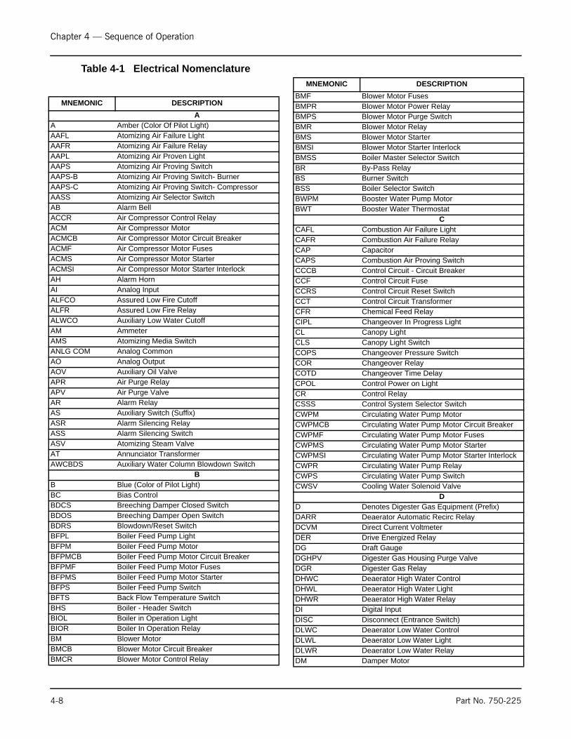
Chapter 4 — Sequence of Operation
Table 4-1 Electrical Nomenclature
MNEMONIC DESCRIPTION
AA Amber (Color Of Pilot Light)AAFL Atomizing Air Failure LightAAFR Atomizing Air Failure RelayAAPL Atomizing Air Proven LightAAPS Atomizing Air Proving SwitchAAPS-B Atomizing Air Proving Switch- BurnerAAPS-C Atomizing Air Proving Switch- CompressorAASS Atomizing Air Selector SwitchAB Alarm BellACCR Air Compressor Control RelayACM Air Compressor MotorACMCB Air Compressor Motor Circuit BreakerACMF Air Compressor Motor FusesACMS Air Compressor Motor StarterACMSI Air Compressor Motor Starter InterlockAH Alarm HornAI Analog InputALFCO Assured Low Fire CutoffALFR Assured Low Fire RelayALWCO Auxiliary Low Water CutoffAM AmmeterAMS Atomizing Media SwitchANLG COM Analog CommonAO Analog OutputAOV Auxiliary Oil ValveAPR Air Purge RelayAPV Air Purge ValveAR Alarm RelayAS Auxiliary Switch (Suffix)ASR Alarm Silencing RelayASS Alarm Silencing SwitchASV Atomizing Steam ValveAT Annunciator TransformerAWCBDS Auxiliary Water Column Blowdown Switch
BB Blue (Color of Pilot Light)BC Bias ControlBDCS Breeching Damper Closed SwitchBDOS Breeching Damper Open SwitchBDRS Blowdown/Reset SwitchBFPL Boiler Feed Pump LightBFPM Boiler Feed Pump MotorBFPMCB Boiler Feed Pump Motor Circuit BreakerBFPMF Boiler Feed Pump Motor FusesBFPMS Boiler Feed Pump Motor StarterBFPS Boiler Feed Pump SwitchBFTS Back Flow Temperature SwitchBHS Boiler - Header SwitchBIOL Boiler in Operation LightBIOR Boiler In Operation RelayBM Blower MotorBMCB Blower Motor Circuit BreakerBMCR Blower Motor Control Relay
4-8
BMF Blower Motor FusesBMPR Blower Motor Power RelayBMPS Blower Motor Purge SwitchBMR Blower Motor RelayBMS Blower Motor StarterBMSI Blower Motor Starter Interlock BMSS Boiler Master Selector SwitchBR By-Pass RelayBS Burner SwitchBSS Boiler Selector SwitchBWPM Booster Water Pump MotorBWT Booster Water Thermostat
CCAFL Combustion Air Failure LightCAFR Combustion Air Failure RelayCAP CapacitorCAPS Combustion Air Proving SwitchCCCB Control Circuit - Circuit BreakerCCF Control Circuit FuseCCRS Control Circuit Reset SwitchCCT Control Circuit TransformerCFR Chemical Feed RelayCIPL Changeover In Progress LightCL Canopy LightCLS Canopy Light SwitchCOPS Changeover Pressure SwitchCOR Changeover RelayCOTD Changeover Time DelayCPOL Control Power on LightCR Control RelayCSSS Control System Selector SwitchCWPM Circulating Water Pump MotorCWPMCB Circulating Water Pump Motor Circuit BreakerCWPMF Circulating Water Pump Motor FusesCWPMS Circulating Water Pump Motor StarterCWPMSI Circulating Water Pump Motor Starter InterlockCWPR Circulating Water Pump RelayCWPS Circulating Water Pump SwitchCWSV Cooling Water Solenoid Valve
DD Denotes Digester Gas Equipment (Prefix)DARR Deaerator Automatic Recirc RelayDCVM Direct Current VoltmeterDER Drive Energized RelayDG Draft GaugeDGHPV Digester Gas Housing Purge ValveDGR Digester Gas RelayDHWC Deaerator High Water ControlDHWL Deaerator High Water LightDHWR Deaerator High Water RelayDI Digital InputDISC Disconnect (Entrance Switch)DLWC Deaerator Low Water ControlDLWL Deaerator Low Water LightDLWR Deaerator Low Water RelayDM Damper Motor
MNEMONIC DESCRIPTION
Part No. 750-225
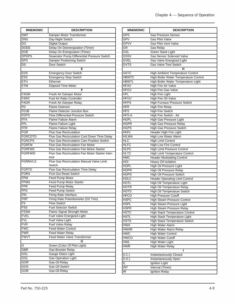
Chapter 4 — Sequence of Operation
DMT Damper Motor TransformerDNS Day-Night SwitchDO Digital OutputDODE Delay On Deenergization (Timer)DOE Delay On Energization (Timer)DPDPS Deaerator Pump Differential Pressure SwitchDPS Damper Positioning SwitchDS Door Switch
EEDS Emergency Door SwitchESS Emergency Stop SwitchETH EthernetETM Elapsed Time Meter
FFADM Fresh Air Damper MotorFARC Fuel Air Ratio ControllerFADR Fresh Air Damper RelayFD Flame DetectorFDJB Flame Detector Junction BoxFDPS Flow Differential Pressure SwitchFFA Flame Failure AlarmFFL Flame Failure LightFFR Flame Failure RelayFGR Flue Gas RecirculationFGRCDTD Flue Gas Recirculation Cool Down Time DelayFGRCPS Flue Gas Recirculation Cam Position SwitchFGRFM Flue Gas Recirculation Fan MotorFGRFMS Flue Gas Recirculation Fan Motor StarterFGRFMSI Flue Gas Recirculation Fan Motor Starter Inter-
lockFGRMVLS Flue Gas Recirculation Manual Valve Limit
SwitchFGRTD Flue Gas Recirculation Time DelayFORS First Out Reset SwitchFPM Feed Pump MotorFPMS Feed Pump Motor StarterFPR Feed Pump RelayFPS Feed Pump SwitchFRI Firing Rate InterfaceFRP Firing Rate Potentiometer (O2 Trim)FS Flow SwitchFSS Fuel Selector SwitchFSSM Flame Signal Strength MeterFVEL Fuel Valve Energized LightFVL Fuel Valve LightFVR Fuel Valve RelayFWC Feed Water ControlFWR Feed Water RelayFWVT Feed Water Valve Transformer
GG Green (Color Of Pilot Light)GBR Gas Booster RelayGGL Gauge Glass LightGOL Gas Operation LightGOR Gas-Oil RelayGOS Gas-Oil SwitchGOR Gas-Oil Relay
MNEMONIC DESCRIPTION
Part No. 750-225
GPS Gas Pressure SensorGPV Gas Pilot ValveGPVV Gas Pilot Vent ValveGR Gas RelayGSL Green Stack LightGSSV Gas Sensor Solenoid ValveGVEL Gas Valve Energized LightGVTS Gas Valve Test Switch
HHATC High Ambient Temperature ControlHBWTC High Boiler Water Temperature ControlHBWTL High Boiler Water Temperature LightHFAV High Fire Air ValveHFGV High Fire Gas ValveHFL High Fire LightHFOV High Fire Oil ValveHFPS High Furnace Pressure SwitchHFR High Fire RelayHFS High Fire SwitchHFS-A High Fire Switch - AirHGPL High Gas Pressure LightHGPR High Gas Pressure RelayHGPS High Gas Pressure SwitchHHFL Header High Fire LightH/LWA High Low Water AlarmHLC High Limit ControlHLFC High-Low Fire ControlHLPC High Limit Pressure ControlHLTC High Limit Temperature ControlHMC Header Modulating ControlHOI Heavy Oil IsolationHOPL High Oil Pressure LightHOPR High Oil Pressure RelayHOPS High Oil Pressure SwitchHOLC Header Operating Limit ControlHOTL High Oil Temperature LightHOTR High Oil Temperature RelayHOTS High Oil Temperature SwitchHPCO High Pressure CutoffHSPC High Steam Pressure ControlHSPL High Steam Pressure LightHSPR High Steam Pressure RelayHSTC High Stack Temperature ControlHSTL High Stack Temperature LightHSTS High Stack Temperature SwitchHWA High Water AlarmHWAR High Water Alarm RelayHWC High Water ControlHWCO High Water CutoffHWL High Water LightHWR High Water Relay
I(I.C.) Instantaneously Closed(I.O.) Instantaneously OpenIL Ignition LightINT Interval (Timer)IR Ignition Relay
MNEMONIC DESCRIPTION
4-9
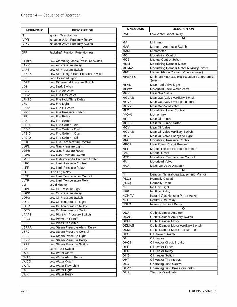
Chapter 4 — Sequence of Operation
IT Ignition TransformerIVPR Isolation Valve Proximity RelayIVPS Isolation Valve Proximity Switch
JJPP Jackshaft Position Potentiometer
LLAMPS Low Atomizing Media Pressure SwitchLAPR Low Air Pressure RelayLAPS Low Air Pressure SwitchLASPS Low Atomizing Steam Pressure SwitchLDL Load Demand LightLDPS Low Differential Pressure SwitchLDS Low Draft SwitchLFAV Low Fire Air ValveLFGV Low Fire Gas ValveLFHTD Low Fire Hold Time DelayLFL Low Fire LightLFOV Low Fire Oil ValveLFPS Low Fire Pressure SwitchLFR Low Fire RelayLFS Low Fire SwitchLFS-A Low Fire Switch - AirLFS-F Low Fire Switch - FuelLFS-G Low Fire Switch - GasLFS-O Low Fire Switch - OilLFTC Low Fire Temperature ControlLGPL Low Gas Pressure LightLGPR Low Gas Pressure RelayLGPS Low Gas Pressure SwitchLIAPS Low Instrument Air Pressure SwitchLLPC Low Limit Pressure ControlLLPR Low Limit Pressure RelayLLR Lead Lag RelayLLTC Low Limit Temperature ControlLLTR Low Limit Temperature RelayLM Level MasterLOPL Low Oil Pressure LightLOPR Low Oil Pressure RelayLOPS Low Oil Pressure SwitchLOTL Low Oil Temperature LightLOTR Low Oil Temperature RelayLOTS Low Oil Temperature SwitchLPAPS Low Plant Air Pressure SwitchLPCO Low Pressure CutoffLPS Low Pressure SwitchLSPAR Low Steam Pressure Alarm RelayLSPC Low Steam Pressure ControlLSPL Low Steam Pressure LightLSPR Low Steam Pressure RelayLSPS Low Steam Pressure SwitchLTS Lamp Test SwitchLWA Low Water AlarmLWAR Low Water Alarm RelayLWCO Low Water CutoffLWFL Low Water Flow LightLWL Low Water LightLWR Low Water Relay
MNEMONIC DESCRIPTION
4-10
LWRR Low Water Reset RelayM
MA Milli-ampMAS Manual - Automatic SwitchMAM MicrometerMC Modulating ControlMCS Manual Control SwitchMDM Modulating Damper MotorMDMAS Modulating Damper Motor Auxiliary SwitchMFC Manual Flame Control (Potentiometer)MFGRTS Minimum Flue Gas Recirculation Temperature
SwitchMFVL Main Fuel Valve LightMFWV Motorized Feed Water ValveMGV Main Gas ValveMGVAS Main Gas Valve Auxiliary SwitchMGVEL Main Gas Valve Energized LightMGVV Main Gas Vent ValveMLC Modulating Level Control(MOM) MomentaryMOP Main Oil PumpMOPS Main Oil Pump StarterMOV Main Oil ValveMOVAS Main Oil Valve Auxiliary SwitchMOVEL Main Oil Valve Energized LightMPC Modulating Pressure ControlMPCB Main Power Circuit BreakerMPP Manual Positioning Potentiometer(MR) Manual ResetMTC Modulating Temperature ControlMV Motorized ValveMVA Make-Up Valve Actuator
NN Denotes Natural Gas Equipment (Prefix)(N.C.) Normally Closed(N.O.) Normally OpenNFL No Flow LightNFR No Flow RelayNGHPV Natural Gas Housing Purge ValveNGR Natural Gas RelayNRLR Nonrecycle Limit Relay
OODA Outlet Damper ActuatorODAS Outlet Damper Auxiliary SwitchODM Outlet Damper MotorODMAS Outlet Damper Motor Auxiliary SwitchODMT Outlet Damper Motor TransformerODS Oil Drawer SwitchOH Oil HeaterOHCB Oil Heater Circuit BreakerOHF Oil Heater FusesOHR Oil Heater RelayOHS Oil Heater SwitchOHT Oil Heater ThermostatOLC Operating Limit ControlOLPC Operating Limit Pressure ControlOL’S Thermal Overloads
MNEMONIC DESCRIPTION
Part No. 750-225
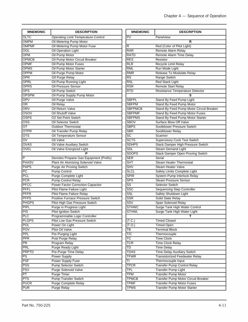
Chapter 4 — Sequence of Operation
OLTC Operating Limit Temperature ControlOMPM Oil Metering Pump MotorOMPMF Oil Metering Pump Motor FuseOOL Oil Operation LightOPM Oil Pump MotorOPMCB Oil Pump Motor Circuit BreakerOPMF Oil Pump Motor FusesOPMS Oil Pump Motor StarterOPPM Oil Purge Pump MotorOPR OIl Purge RelayOPRL Oil Pump Running LightOPRS Oil Pressure SensorOPS Oil Pump SwitchOPSPM Oil Pump Supply Pump MotorOPV Oil Purge ValveOR Oil RelayORV Oil Return ValveOSOV Oil Shutoff ValveOSPS O2 Set Point SwitchOSS Oil Selector SwitchOT Outdoor ThermostatOTPR Oil Transfer Pump RelayOTS Oil Temperature SensorOV Oil ValveOVAS Oil Valve Auxiliary SwitchOVEL Oil Valve Energized Light
PP Denotes Propane Gas Equipment (Prefix)PAASV Plant Air Atomizing Solenoid ValvePAPS Purge Air Proving SwitchPC Pump ControlPCL Purge Complete LightPCR Pump Control RelayPFCC Power Factor Correction CapacitorPFFL Pilot Flame Failure LightPFFR Pilot Flame Failure RelayPFPS Positive Furnace Pressure SwitchPHGPS Pilot High Gas Pressure SwitchPIPL Purge in Progress LightPIS Pilot Ignition SwitchPLC Programmable Logic ControllerPLGPS Pilot Low Gas Pressure SwitchPOL Power On LightPOV Pilot Oil ValvePPL Pre-Purging LightPPR Post Purge RelayPR Program RelayPRL Purge Ready LightPRPTD Pre-Purge Time DelayPS Power SupplyPSF Power Supply FusePSS Pump Selector SwitchPSV Purge Solenoid ValvePT Purge TimerPTS Pump Transfer SwitchPUCR Purge Complete RelayPUR Purge Relay
MNEMONIC DESCRIPTION
P
RRRRRRRRRRR
SSSSSSSSSSSSSSSSSSSSSSSSSS
(T(TTTTTTTTTTTTTTT
Part No. 750-225
V PanelviewR
Red (Color of Pilot Light)AR Remote Alarm RelayATD Remote Alarm Time DelayES ResistorLR Recycle Limit RelayML Run Mode LightMR Release To Modulate RelayS Range SwitchSL Red Stack LightSR Remote Start RelayTD Resistance Temperature Detector
SBFPL Stand By Feed Pump LightBFPM Stand By Feed Pump MotorBFPMCB Stand By Feed Pump Motor Circuit BreakerBFPMF Stand By Feed Pump Motor FusesBFPMS Stand By Feed Pump Motor StarterBOV Surface Blow Off ValveBPS Sootblower Pressure SwitchBR Sootblower RelayC ScannerCTS Supervisory Cock Test SwitchDHPS Stack Damper High Pressure SwitchDL Steam Demand LightDOPS Stack Damper Open Proving SwitchER SerialHT Steam Heater ThermostatHV Steam Heater ValveLCL Safety Limits Complete LightPIR System Pump Interlock RelayPS Steam Pressure SensorS Selector SwitchSC Sequencing Step ControllerSL Safety Shutdown LightSR Solid State RelaySV Span Solenoid RelayTHWC Surge Tank High Water ControlTHWL Surge Tank High Water Light
T.C.) Timed Closed.O.) Timed Open
B Terminal Block/C ThermocoupleC Time ClockCR Time Clock RelayD Time DelayDAS Time Delay Auxiliary SwitchFWR Transistorized Feedwater RelayI Thermocouple InputPCR Transfer Pump Control RelayPL Transfer Pump LightPM Transfer Pump MotorPMCB Transfer Pump Motor Circuit BreakerPMF Transfer Pump Motor FusesPMS Transfer Pump Motor Starter
MNEMONIC DESCRIPTION
4-11
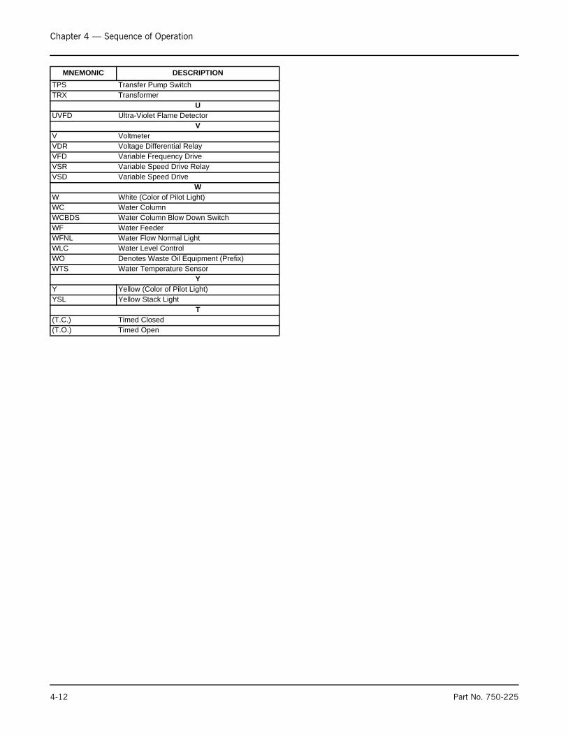
Chapter 4 — Sequence of Operation
TPS Transfer Pump SwitchTRX Transformer
UUVFD Ultra-Violet Flame Detector
VV VoltmeterVDR Voltage Differential RelayVFD Variable Frequency DriveVSR Variable Speed Drive RelayVSD Variable Speed Drive
WW White (Color of Pilot Light)WC Water ColumnWCBDS Water Column Blow Down SwitchWF Water FeederWFNL Water Flow Normal LightWLC Water Level ControlWO Denotes Waste Oil Equipment (Prefix)WTS Water Temperature Sensor
YY Yellow (Color of Pilot Light)YSL Yellow Stack Light
T(T.C.) Timed Closed(T.O.) Timed Open
MNEMONIC DESCRIPTION
4-12 Part No. 750-225
Milwaukee, Wisconsin
www.cleaver-brooks.com
Chapter 5Starting and Operating Instructions
Contents
A. GENERAL PREPARATION FOR START-UP, ALL FUELS . . . . . . . 5-3B. CONTROL SETTINGS - STEAM AND HOT WATER . . . . . . . . . . 5-4C. GAS PILOT . . . . . . . . . . . . . . . . . . . . . . . . . . . . . . . . . . . . . 5-5D. ATOMIZING AIR . . . . . . . . . . . . . . . . . . . . . . . . . . . . . . . . . 5-6E. FIRING PREPARATIONS FOR NO. 2 OIL (SERIES 100-200) . . 5-7F. FIRING PREPARATION FOR NO. 6 OIL (SERIES 400-600) . . . . 5-8G. FIRING PREPARATIONS FOR GAS (SERIES 200-400-700) . . 5-10H. IFGR SETUP . . . . . . . . . . . . . . . . . . . . . . . . . . . . . . . . . . . 5-11I. START-UP, OPERATING AND SHUTDOWN - ALL FUELS . . . . . 5-14J. CONTROL OPERATIONAL TEST AND CHECKS . . . . . . . . . . . 5-15

Chapter 5 — Starting and Operating Instructions
A.GENERAL PREPARATION FOR START-UP, ALL FUELS
Instructions in Chapter 5 are all based upon installation beingcomplete and all electrical, fuel, water and vent stack connectionsare made.
The operator should be familiar with the burner, boiler, and allcontrols and components. To quickly locate and identify the variouscontrols and components mentioned in the following paragraphs,refer to the illustrations and the contents of Chapters 1, 2 and 3.Instructions for adjusting major components are given in Chapter 6this should be reviewed prior to firing. The wiring diagram shouldalso have been studied, along with the firing sequence outlined inChapter 4.
Verify supply of fuel and proper voltage. Check for blown fuses,open circuit breakers, dropped out overloads, etc. Check reset of allstarters and controls having manual reset features. Check thelockout switch on the programmer and reset if necessary.
The boiler should be filled with water to the proper operating levelusing water of ambient temperature. Be sure that treated feedwateris available and used. In heating applications, the entire systemshould be filled and vented. Refer to Chapter 3 for waterrequirements. On a steam boiler, open the test valve (Chapter 1,Figure 1-7) to vent air displaced during filling. Leave the test valveopen until the escape of steam is noted after the burner is operating.
Check all linkage for full and free movement of the damper andmetering valves and cams. The check can be done by loosening thelinkage at the damper motor connecting arm and manipulating thelinkage by hand.
Check for rotation of all motors by momentarily closing the motorstarter or relay. The blower impeller rotation is counter-clockwisewhen viewed from the front of the boiler. The air pump rotation isclockwise when viewed from its drive end.
Before operating the boiler feed pump or oil supply pump, be sureall valves in the line are open or properly positioned.
For safety reasons, perform a final pre-startup inspection, especiallychecking for any loose or incomplete piping or wiring or any othersituations that might present a hazard.
NoticeIf your boiler is equipped with aCB -HAWK ICS bo i l e rmanagement control system, referto CB-HAWK ICS Operation,Servicing and Parts Manual No.750-197 for specific informationprocedures described in sectionA.
! WarningIt is recommended that thestarting instructions be readcompletely until they arethoroughly understood, beforeattempting to operate theboiler, rather than performingeach operation as it is read forthe first time. Failure to followthese instructions could resultin serious personal injury ordeath
! WarningPrior to firing a boiler, be surethat discharge piping fromsafety valves or relief valves,and discharge piping from allblowdown and drain valves, ispiped to a SAFE point ofdischarge, so that emission ofhot water or steam cannotpossibly cause injury. Failureto follow these instructionscou ld resu l t in se r iouspersonal injury or death
NoticeThe pressure vessel support legs are welded to mountingskids in front and secured by bolts at the rear of the pressurevessel. The bolts are tightened for shipment. When the boileris installed, and prior to initial firing, the bolts securing therear legs to the skid must be loosened to allow for expansionand contraction caused by differences in temperaturebetween pressure vessel and skids and to avoid damage tothe equipment.
5-2 Part No. 750-225

Chapter 5 — Starting and Operating Instructions
B. CONTROL SETTINGS - STEAM AND HOT WATER
See Chapter 6 for adjustment instructions for the following controls
.Inspect the operating limit control for proper setting.
1. The pressure control of a steam boiler should be set slightlyabove the highest desired steam pressure, but at least 10%lower than the setting of the safety valve.
2. The temperature control on a hot water boiler should be setslightly above the highest desired water temperature and withinthe limits of the pressure vessel.
Inspect the high limit control for proper setting.
3. On a high pressure steam boiler, the control should be setapproximately 10 psig above the operating limit pressure controlsetting, if feasible, or midway between the operating limitpressure and the safety valve setting. The setting on a lowpressure steam boiler may be 2 o r 3 psig above the operatinglimit setting, but must not exceed the safety valve setting.
4. On a hot water boiler, the high limit temperature control shouldbe 5-10°F above the operating limit temperature control settingbut within the limits of the design pressure of the pressurevessel.
Figure 5-1 Fan Motor
FAN MOTOR ROTATION COUNTERCLOCKWISE
Figure 5-2 Air Compressor
AIR COMPRESSOR ROTATION CLOCKWISE FROM DRIVE END
Figure 5-3 Hot Water Controls
Part No. 750-225 5-3
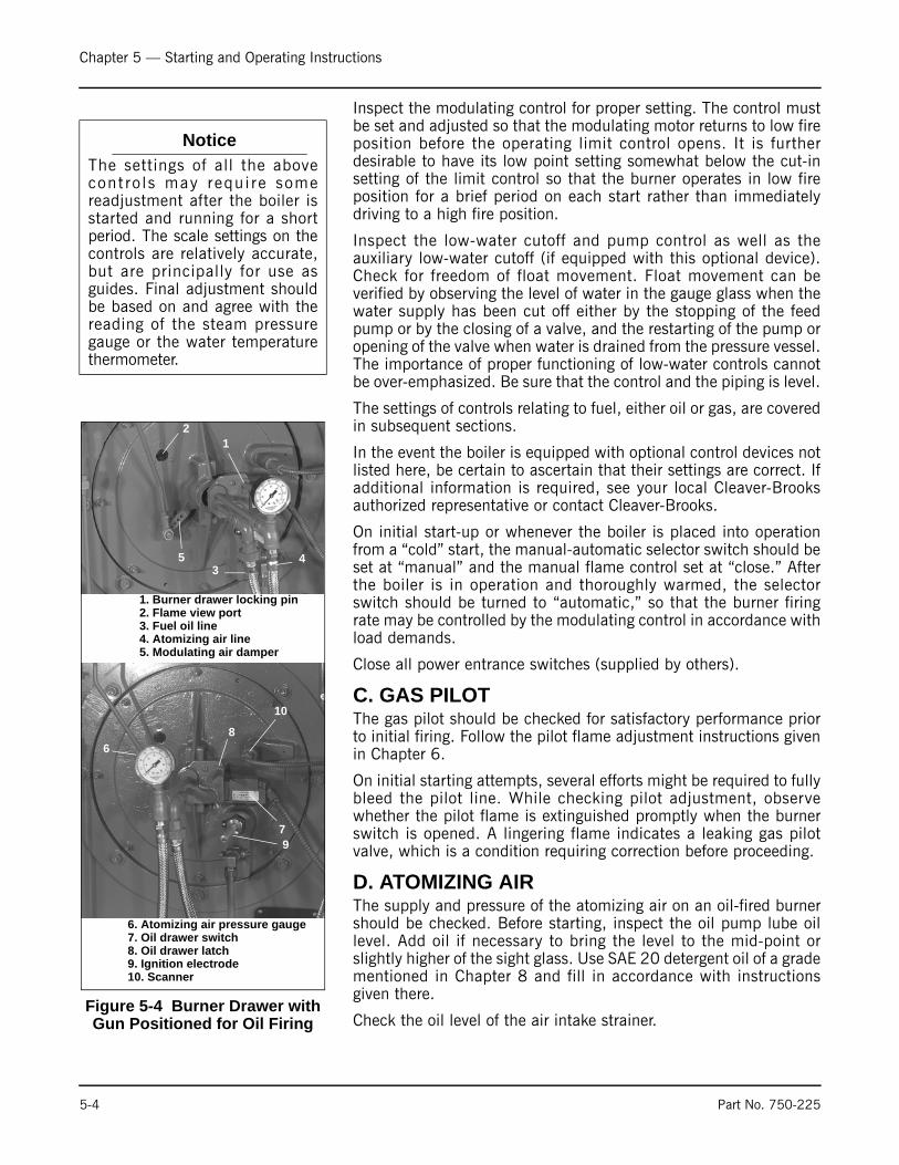
Chapter 5 — Starting and Operating Instructions
Inspect the modulating control for proper setting. The control mustbe set and adjusted so that the modulating motor returns to low fireposition before the operating limit control opens. It is furtherdesirable to have its low point setting somewhat below the cut-insetting of the limit control so that the burner operates in low fireposition for a brief period on each start rather than immediatelydriving to a high fire position.
Inspect the low-water cutoff and pump control as well as theauxiliary low-water cutoff (if equipped with this optional device).Check for freedom of float movement. Float movement can beverified by observing the level of water in the gauge glass when thewater supply has been cut off either by the stopping of the feedpump or by the closing of a valve, and the restarting of the pump oropening of the valve when water is drained from the pressure vessel.The importance of proper functioning of low-water controls cannotbe over-emphasized. Be sure that the control and the piping is level.
The settings of controls relating to fuel, either oil or gas, are coveredin subsequent sections.
In the event the boiler is equipped with optional control devices notlisted here, be certain to ascertain that their settings are correct. Ifadditional information is required, see your local Cleaver-Brooksauthorized representative or contact Cleaver-Brooks.
On initial start-up or whenever the boiler is placed into operationfrom a “cold” start, the manual-automatic selector switch should beset at “manual” and the manual flame control set at “close.” Afterthe boiler is in operation and thoroughly warmed, the selectorswitch should be turned to “automatic,” so that the burner firingrate may be controlled by the modulating control in accordance withload demands.
Close all power entrance switches (supplied by others).
C. GAS PILOTThe gas pilot should be checked for satisfactory performance priorto initial firing. Follow the pilot flame adjustment instructions givenin Chapter 6.
On initial starting attempts, several efforts might be required to fullybleed the pilot line. While checking pilot adjustment, observewhether the pilot flame is extinguished promptly when the burnerswitch is opened. A lingering flame indicates a leaking gas pilotvalve, which is a condition requiring correction before proceeding.
D. ATOMIZING AIRThe supply and pressure of the atomizing air on an oil-fired burnershould be checked. Before starting, inspect the oil pump lube oillevel. Add oil if necessary to bring the level to the mid-point orslightly higher of the sight glass. Use SAE 20 detergent oil of a gradementioned in Chapter 8 and fill in accordance with instructionsgiven there.
Check the oil level of the air intake strainer.
NoticeThe settings of all the abovecont ro ls may requ i re somereadjustment after the boiler isstarted and running for a shortperiod. The scale settings on thecontrols are relatively accurate,but are principally for use asguides. Final adjustment shouldbe based on and agree with thereading of the steam pressuregauge or the water temperaturethermometer.
Figure 5-4 Burner Drawer with Gun Positioned for Oil Firing
1. Burner drawer locking pin2. Flame view port3. Fuel oil line4. Atomizing air line5. Modulating air damper
6. Atomizing air pressure gauge7. Oil drawer switch8. Oil drawer latch9. Ignition electrode10. Scanner
12
345
6
7
8
9
10
5-4 Part No. 750-225
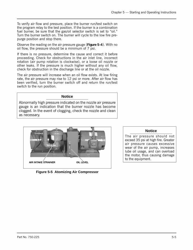
Chapter 5 — Starting and Operating Instructions
To verify air flow and pressure, place the burner run/test switch onthe program relay to the test position. If the burner is a combinationfuel burner, be sure that the gas/oil selector switch is set to “oil.”Turn the burner switch on. The burner will cycle to the low fire pre-purge position and stop there.
Observe the reading on the air pressure gauge (Figure 5-4). With nooil flow, the pressure should be a minimum of 7 psi.
If there is no pressure, determine the cause and correct it beforeproceeding. Check for obstructions in the air inlet line, incorrectrotation (air pump rotation is clockwise), or a loose oil nozzle orother leaks. If the pressure is much higher without any oil flow,check for obstruction in the discharge line or at the oil nozzle.
The air pressure will increase when an oil flow exists. At low firingrate, the air pressure may rise to 12 psi or more. After air flow hasbeen verified, turn the burner switch off and return the run/testswitch to the run position.
NoticeAbnormally high pressure indicated on the nozzle air pressuregauge is an indication that the burner nozzle has becomeclogged. In the event of clogging, check the nozzle and cleanas necessary.
NoticeThe air pressure should notexceed 35 psi at high fire. Greaterair pressure causes excessivewear of the air pump, increaseslube oil usage, and can overloadthe motor, thus causing damageto the equipment.
Figure 5-5 Atomizing Air Compressor
AIR INTAKE STRAINER OIL LEVEL
Part No. 750-225 5-5

Chapter 5 — Starting and Operating Instructions
E. FIRING PREPARATIONS FOR NO. 2 OIL (SERIES 100-200)
Prior to initial firing, oil flow and pressure should be established andverified. Atomizing air pressure should also be established asoutlined in Section D. The schematic flow diagram (Chapter 2,Figure 2-23) indicates the flow of fuel and atomizing air.
If the burner is a combination fuel model, be certain that the maingas shutoff cock is closed and set the gas/oil selector switch to “oil.”Insert the burner drawer gun into its most forward position and latchit in place (see Figure 5-7).
Oil Flow - Open all valves in the oil suction and oil return lines.
If the oil supply tank is located above the level of the pump and flowto the pump is by gravity, then it will usually be necessary to ventthe suction line to allow oil to fill the line. Venting the suction linecan generally be accomplished by cracking a union fitting, or byopening the cap of the oil strainer using care to prevent spillage ofoil. Tighten the fitting or the cap as soon as oil flow appears.
If the oil supply tank is below the level of the oil pump, it isMANDATORY that the suction line to the pump be completely filledwith oil prior to starting the pump to avoid the possibility of damageto the pump gears. Non-lubricating fluids such as kerosene shouldnot be used for priming.
Prior to priming the suction line and the initial start, check to makecertain that all plugs, connections, etc., have been securelytightened to prevent leaks.
If the fuel oil supply originates from a pressurized loop, it isassumed that the pressure of the loop will be at a minimum of 75psi. Under these conditions, the relief valve at the terminal blockshould be adjusted to the point where it becomes inoperative (orremoved and openings plugged). To render inoperative, turn theadjusting screw in as far as possible.
A standard equipped boiler has a selector switch incorporated in theoil pump motor starter. Momentarily energize the starter to checkfor proper pump rotation. With the rotation verified, operate thepump to determine that oil circulation exists. Observe the oil burnerpressure gauge for indication that flow is established. If no pressureshows on the gauge after a few moments, stop the oil pump and re-prime. If the supply tank is lower than the pump, it is possible thatthe initial priming of the suction line, followed by operation of thepump, will not establish oil flow. This might be caused byobstruction in the suction line, excessive lift, inadequate priming,suction line leaks, etc. If oil flow is not readily established, avoidprolonged operation of the pump to minimize risk of damage tointernal parts of the pump. If oil flow is not established after asecond or third priming attempt, a full investigation is required todetermine the cause.
A vacuum (or a compound pressure-vacuum) gauge should beinstalled at the suction port of the pump and its reading observed
Figure 5-6 Oil Piping
OIL BURNER PRESSURE GAUGE
Figure 5-7 Gun Locked In, Firing Oil
Figure 5-8 Oil Drawer Closed, Firing Oil
5-6 Part No. 750-225
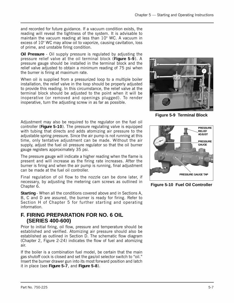
Chapter 5 — Starting and Operating Instructions
and recorded for future guidance. If a vacuum condition exists, thereading will reveal the tightness of the system. It is advisable tomaintain the vacuum reading at less than 10" WC. A vacuum inexcess of 10" WC may allow oil to vaporize, causing cavitation, lossof prime, and unstable firing condition.
Oil Pressure - Oil supply pressure is regulated by adjusting thepressure relief valve at the oil terminal block (Figure 5-9). Apressure gauge should be installed in the terminal block and therelief valve adjusted to obtain a minimum reading of 75 psi whenthe burner is firing at maximum rate.
When oil is supplied from a pressurized loop to a multiple boilerinstallation, the relief valve in the loop should be properly adjustedto provide this reading. In this circumstance, the relief valve at theterminal block should be adjusted to the point when it will beinoperative (or removed and openings plugged). To renderinoperative, turn the adjusting screw in as far as possible.
Adjustment may also be required to the regulator on the fuel oilcontroller (Figure 5-10). The pressure regulating valve is equippedwith tubing that directs and adds atomizing air pressure to theadjustable spring pressure. Since the air pump is not running at thistime, only tentative adjustment can be made. Without the airsupply, adjust the fuel oil pressure regulator so that the oil burnergauge registers approximately 35 psi.
The pressure gauge will indicate a higher reading when the flame ispresent and will increase as the firing rate increases. After theburner is firing and when the air pump is running, final adjustmentcan be made at the fuel oil controller.
Final regulation of oil flow to the nozzle can be done later, ifnecessary, by adjusting the metering cam screws as outlined inChapter 6.
Starting - When all the conditions covered above and in Sections A,B, C and D are assured, the burner is ready for firing. Refer toSection H of Chapter 5 for further starting and operatinginformation.
F. FIRING PREPARATION FOR NO. 6 OIL (SERIES 400-600)
Prior to initial firing, oil flow, pressure and temperature should beestablished and verified. Atomizing air pressure should also beestablished as outlined in Section D. The schematic flow diagram(Chapter 2, Figure 2-24) indicates the flow of fuel and atomizingair.
If the boiler is a combination fuel model, be certain that the maingas shutoff cock is closed and set the gas/oil selector switch to “oil.”Insert the burner drawer gun into its most forward position and latchit in place (see Figure 5-7, and Figure 5-8).
Figure 5-9 Terminal Block
Figure 5-10 Fuel Oil Controller
PRESSUREGAUGE
PRESSURERELIEFADJUST
PRESSURE GAUGE TAP
Part No. 750-225 5-7
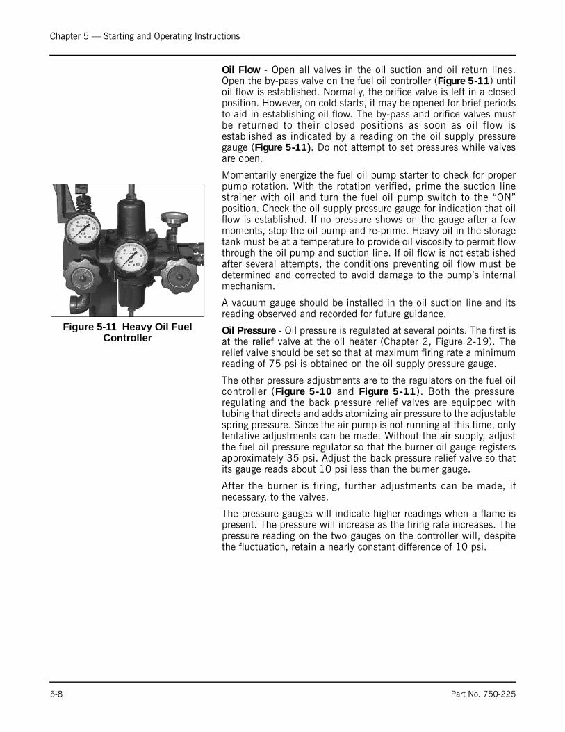
Chapter 5 — Starting and Operating Instructions
Oil Flow - Open all valves in the oil suction and oil return lines.Open the by-pass valve on the fuel oil controller (Figure 5-11) untiloil flow is established. Normally, the orifice valve is left in a closedposition. However, on cold starts, it may be opened for brief periodsto aid in establishing oil flow. The by-pass and orifice valves mustbe returned to their closed positions as soon as oil flow isestablished as indicated by a reading on the oil supply pressuregauge (Figure 5-11). Do not attempt to set pressures while valvesare open.
Momentarily energize the fuel oil pump starter to check for properpump rotation. With the rotation verified, prime the suction linestrainer with oil and turn the fuel oil pump switch to the “ON”position. Check the oil supply pressure gauge for indication that oilflow is established. If no pressure shows on the gauge after a fewmoments, stop the oil pump and re-prime. Heavy oil in the storagetank must be at a temperature to provide oil viscosity to permit flowthrough the oil pump and suction line. If oil flow is not establishedafter several attempts, the conditions preventing oil flow must bedetermined and corrected to avoid damage to the pump’s internalmechanism.
A vacuum gauge should be installed in the oil suction line and itsreading observed and recorded for future guidance.
Oil Pressure - Oil pressure is regulated at several points. The first isat the relief valve at the oil heater (Chapter 2, Figure 2-19). Therelief valve should be set so that at maximum firing rate a minimumreading of 75 psi is obtained on the oil supply pressure gauge.
The other pressure adjustments are to the regulators on the fuel oilcontroller (Figure 5-10 and Figure 5-11). Both the pressureregulating and the back pressure relief valves are equipped withtubing that directs and adds atomizing air pressure to the adjustablespring pressure. Since the air pump is not running at this time, onlytentative adjustments can be made. Without the air supply, adjustthe fuel oil pressure regulator so that the burner oil gauge registersapproximately 35 psi. Adjust the back pressure relief valve so thatits gauge reads about 10 psi less than the burner gauge.
After the burner is firing, further adjustments can be made, ifnecessary, to the valves.
The pressure gauges will indicate higher readings when a flame ispresent. The pressure will increase as the firing rate increases. Thepressure reading on the two gauges on the controller will, despitethe fluctuation, retain a nearly constant difference of 10 psi.
Figure 5-11 Heavy Oil Fuel Controller
5-8 Part No. 750-225
Chapter 5 — Starting and Operating Instructions
Final regulation of oil flow to the nozzle can be done, if necessary,by adjusting the metering cam screws as outlined in Chapter 6.
Oil Temperature -
After determining that the heater shell is filled and that fuel oilcirculation exists, turn the oil heater switch to “on.” Adjust theelectric oil heater thermostat (Chapter 2, Figure 2-19) to maintainoil temperature at approximately 200°F.
The electric heater on burners equipped for No. 6 fuel oil is sized sothat it is capable of supplying heated oil at a rate no greater thanthat required for low fire operation and is primarily supplied forconvenience on cold starts. Heating coils utilizing either steam orhot water are supplied to provide sufficient heat so that higher ratesof firing can be accomplished once steam pressure or hot water isavailable. In normal operation, the thermostat governing the electricheating element is kept at a lower setting than the thermostatgoverning admission of steam to the heater, or of hot watercirculation, so that heating is not performed electrically except whensteam or hot water is not available.
Set the steam thermostat (Chapter 2, Figure 2-19) or the hot waterthermostat (Chapter 2, Figure 2-19) to maintain an oil temperatureof 220-230°F. The electric heater will be turned off automaticallyas soon as steam or hot water provides heat.
Close the manual by-pass valve after the temperature rise on thefuel oil controller thermometer is noted. Be certain that hot oil ismoving through the controller. The orifice gate valve must also beclosed. If the temperature drops, open the orifice gate valve until arise is noted, then close it.
Once the correct setting of the heater thermostats has beenestablished, set the low oil temperature switch (Chapter 2, Figure2-19) at the point approximately 30°F lower than the normalburning temperature. If the system is equipped with a high oiltemperature switch, it should be set to open at 20 -30°F higherthan normal burning temperature.
Starting - When all the conditions covered above and in Sections A,B, C and D are assured, the burner is ready for firing. Refer toSection H of Chapter 5 for further starting and operatinginformation.
G. FIRING PREPARATIONS FOR GAS (SERIES 200-400-700)
• Prior to initial starting, check the linkage attached to the gas butterfly valve to assure that movement is free from binding.
• Verify the presence and availability of gas. On a new installation, representatives of the gas utility should be present when gas first flows into the system to supervise purging of the new gas line, unless they have already done so.
• Determine that the pilot is operating properly, as outlined in Section C, Chapter 5.
! CautionBefore turning on the electric oilheater switch, be certain that theheater shell is filled with fuel oiland the flow is established.Fa i lu re to f o l l ow theseinstructions could result inequipment damage.
NoticeThe temperatures l isted aretentative. The composition of thefuel oil in a given grade can vary,necessitating a higher or lowerpreheating temperature. Theviscosity of the oil at the nozzleshould be less than 300 SSU andpreferably less than 150 SSU.The actual temperature of the oila t the bu rne r shou ld bedetermined by flame appearanceand good combustion based on astack analysis. See Chapter 5 foradditional information.
Part No. 750-225 5-9

Chapter 5 — Starting and Operating Instructions
• Determine that sufficient pressure exists at the entrance to the gas train by installing a test gauge downstream of the regulator.
• The gas pressure regulator must be adjusted to the proper pressure level. Since the regulator is generally supplied by others, adjustment should proceed according to instructions supplied by its manufacturer.
It is necessary for the operator to know the burner requirements ingas quantity and pressure. The information can generally be foundon the Dimension Diagram (DD) supplied by Cleaver-Brooks for thespecific installation. Should the information not be readily available,consult the Cleaver-Brooks Service Department giving the boilerserial number. Chapter 6 contains additional information along withstandard gas flow and pressure requirements.
• If the burner is a combination fuel model, set the gas/oil switch to “gas.” Withdraw the oil burner gun and latch it in its rearward position (Figure 5-12).
• On initial start-up, it is recommended that the main gas shutoff cock (Chapter 2, Figure 2-14) remains closed until the programmer has cycled through prepurge and pilot sequences. When the fuel light on the control panel comes on, observe the action of the motorized gas valve stem to determine that it opens when energized. As soon as it is confirmed, turn the burner switch “OFF” and let programmer finish its cycle. Check that the gas valve has closed. Again, turn the burner “ON”. When the fuel valve light glows, slowly open the main gas cock. Main flame should ignite unless there is air present in the line. If the flame is not established within about 5 seconds, turn the burner switch “off” and allow the programmer to recycle normally for a new lighting trial. Several efforts may be necessary to “bleed” air from the line.
The burner and control system is designed to provide a “prepurge”period of fan operation prior to establishing ignition spark and pilotflame. Do not attempt to alter the system or to take any action thatmight circumvent the feature.
Once the main flame is established, turn the burner switch to the“OFF” position and observe that the flame is extinguished promptly.The flame may continue to burn for a second or two after normalshutdown due to the gas remaining downstream from the fuel valve.If the flame continues to burn for a longer period or during blowermotor spindown, it could indicate a main gas valve leak.Immediately turn the burner switch off and close the main gas cock.Investigate and correct the cause of the valve leakage beforerelighting the burner. The main gas valve should provide a tightseal, provided nothing prevents tight closure. Foreign material maybe present in either the new or renovated gas lines unless adequatecare is taken in cleaning and purging.
Figure 5-12 Oil Gun Locked in OUT Position
! WarningDo not repeat unsuccessfullighting attempts without re-checking the burner and pilotadjustments. Failure to followthese instructions could resultin serious personal injury ordeath
5-10 Part No. 750-225

Chapter 5 — Starting and Operating Instructions
When the conditions covered in Section G and in Sections A, B andC are assured, the burner is ready for firing. Refer to Section H,Chapter 5 for further starting and operating information.
H. IFGR SETUP It is recommended that the final “installed” settings as noted onFigure 5-13, Figure 5-14 and Figure 5-15 be recorded for futurereference. The settings should be marked on the linkage as well.
Normally, once the system has been set and adjusted, the settingsshould not be changed unless conditions (including boiler settings)change. In that case, it will be necessary to contact your localCleaver-Brooks authorized representative for assistance.
After the IFGR system is initially set up, it will start up with theboiler as an integrated boiler system. After shut down periods inwhich maintenance and /or adjustments have been performed onthe fuel cams, fuel and air linkages, or IFGR control linkages, therecommended approach to start-up is as follows:
1. Set all boiler components to their initial settings as discussed inthe appropriate chapters of this Operation and Maintenancemanual.
2. Check fan impeller and motor rotation. Correct rotation iscounter-clockwise when viewed from the front of the boiler.
3. Verify that all the IFGR components are set to the settingsrecorded on the Start Up report or in Figure 5-13, Figure 5-14and Figure 5-15 (as noted by the Cleaver-Brooks authorizedrepresentative during original set up). Be sure that all linkagesare secure.
4. Start and warm the boiler as described in this Operation andMaintenance manual.
5. Adjust the boiler components as described in this Operation andMaintenance manual to achieve proper boiler operation.
Refer to Chapter 8, Figure 8-8 for instructions on cassette removaland installation.
NoticeThe burner and control system is designed to provide a “prepurge” period of fan operation prior to establishing ignition spark and pilot flame. Do not attempt to alter the system or to take any action that might circumvent the feature.
NoticeInitial IFGR linkage settingsand adjustments must beestablished by a Cleaver-B rooks au tho r i zedrepresentative. Set up of the LEOption requires simultaneousconsideration of air-to-fuelratios and NOx levels. This canonly be accomplished withproper combustion emissionsmonitoring equipment withNOx, O2, CO, and smoke spotmeasuring capability.
Part No. 750-225 5-11
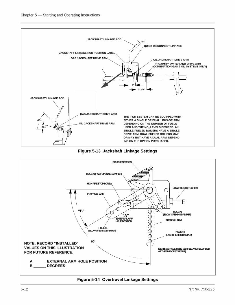
Chapter 5 — Starting and Operating Instructions
Figure 5-13 Jackshaft Linkage Settings
JACKSHAFT LINKAGE ROD
GAS JACKSHAFT DRIVE ARM
OIL JACKSHAFT DRIVE ARM40∞
20∞
THE IFGR SYSTEM CAN BE EQUIPPED WITH EITHER A SINGLE OR DUAL LINKAGE ARM, DEPENDING ON THE NUMBER OF FUELS USED AND THE NOX LEVELS DESIRED. ALL SINGLE-FUELED BOILERS HAVE A SINGLE DRIVE ARM. DUAL-FUELED BOILERS MAY OR MAY NOT HAVE A DUAL ARM, DEPEND-ING ON THE OPTION PURCHASED.
JACKSHAFT LINKAGE ROD
GAS JACKSHAFT DRIVE ARM
QUICK DISCONNECT LINKAGE
OIL JACKSHAFT DRIVE ARM
PROXIMITY SWITCH AND DRIVE ARM(COMBINATION GAS & OIL SYSTEMS ONLY)
2”
2-3/4”
JACKSHAFT LINKAGE ROD POSITION LABEL
Figure 5-14 Overtravel Linkage Settings
DOUBLE SPRINGS
HIGH-FIRE STOP SCREW
HOLE #1 (FAST OPENING DAMPER)
LOW-FIRE STOP SCREW
HOLE #1(SLOW -OPENING DAMPER)
HOLE #5
INTERNAL ARM
EXTERNAL ARM
HOLE # 8(FAST OPENING DAMPER)
(SETTINGS HAVE TO BE VERIFIED AND RECORDED
“A”“B”
HOLE POSITION
90°
(SLOW-OPENING DAMPER)
EXTERNAL ARM
NOTE: RECORD “INSTALLED”VALUES ON THIS ILLUSTRATIONFOR FUTURE REFERENCE.
A.______ EXTERNAL ARM HOLE POSITIONB.______ DEGREES
AT THE TIME OF START UP)
5-12 Part No. 750-225
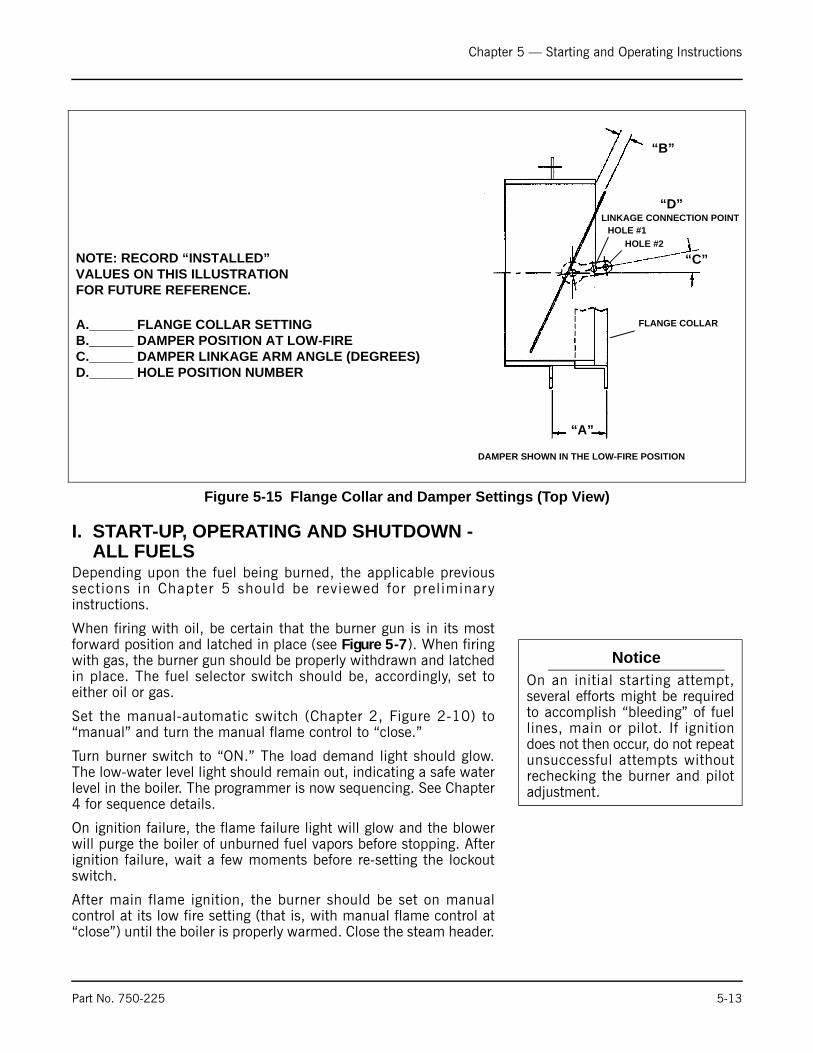
Chapter 5 — Starting and Operating Instructions
I. START-UP, OPERATING AND SHUTDOWN - ALL FUELS
Depending upon the fuel being burned, the applicable previoussections in Chapter 5 should be reviewed for preliminaryinstructions.
When firing with oil, be certain that the burner gun is in its mostforward position and latched in place (see Figure 5-7). When firingwith gas, the burner gun should be properly withdrawn and latchedin place. The fuel selector switch should be, accordingly, set toeither oil or gas.
Set the manual-automatic switch (Chapter 2, Figure 2-10) to“manual” and turn the manual flame control to “close.”
Turn burner switch to “ON.” The load demand light should glow.The low-water level light should remain out, indicating a safe waterlevel in the boiler. The programmer is now sequencing. See Chapter4 for sequence details.
On ignition failure, the flame failure light will glow and the blowerwill purge the boiler of unburned fuel vapors before stopping. Afterignition failure, wait a few moments before re-setting the lockoutswitch.
After main flame ignition, the burner should be set on manualcontrol at its low fire setting (that is, with manual flame control at“close”) until the boiler is properly warmed. Close the steam header.
Figure 5-15 Flange Collar and Damper Settings (Top View)
“A”
“D”
FLANGE COLLAR
HOLE #1HOLE #2
LINKAGE CONNECTION POINT
DAMPER SHOWN IN THE LOW-FIRE POSITION
“B”
“C”NOTE: RECORD “INSTALLED”VALUES ON THIS ILLUSTRATIONFOR FUTURE REFERENCE.
A.______ FLANGE COLLAR SETTINGB.______ DAMPER POSITION AT LOW-FIREC.______ DAMPER LINKAGE ARM ANGLE (DEGREES)D.______ HOLE POSITION NUMBER
NoticeOn an initial starting attempt,several efforts might be requiredto accomplish “bleeding” of fuellines, main or pilot. If ignitiondoes not then occur, do not repeatunsuccessful attempts withoutrechecking the burner and pilotadjustment.
Part No. 750-225 5-13

Chapter 5 — Starting and Operating Instructions
In the case of a steam boiler, CLOSE THE TEST VALVE when thesteam begins to appear.
A hot water boiler must have a continuous flow of system waterthrough the vessel during the warm-up period. The entire watercontent of the system and boiler must be warmed prior to increasingfuel input.
If the flame at low fire provides insufficient heat to reach normaloperating pressure or temperature after 30 minutes, graduallyincrease the firing rate by turning the manual flame control in onepoint increments to no higher than the third cam screw. Operate atthe increased fuel input rate for a period of time until an increase isnoted in pressure or temperature.
After the boiler is thoroughly warmed, turn the manual flame controlto high fire. At this point a combustion analysis should be made,with instruments, and fuel flow regulated as required. Refer to theadjustment procedures in Chapter 6. After making the high-fireadjustment, manually decrease the firing rate, stopping at each camscrew to analyze combustion gases, and adjust as required.
To properly perform the testing and adjusting, it is necessary thatthe burner be allowed to fire at a maximum rate long enough toachieve desired results.
Operating - Normal operation of the burner should be with theswitch in the automatic position and under the direction of themodulating control. The manual position is provided for initialadjustment of the burner over the entire firing range. When ashutdown occurs while operating in the manual position at otherthan low fire, the damper will not be in a closed position, thusallowing more air than desired to flow through the boiler. The hotflame to cool air cycling subjects the pressure vessel metal andrefractory to undesirables conditions.
With the switch set at “auto,” the burner will operate on amodulating basis according to the load demand.
The burner will continue to operate with modulated firing until theoperating limit pressure or temperature is reached, unless:
1. The burner is manually turned “off.”2. The low-water condition is detected by low-water level
control.3. The electrical or fuel supply is interrupted.4. The combustion air pressure or atomizing air pressure drops
below minimum level.
NoticeNote: There can be other reasons for shutdown such asmotor overload, flame outages, tripped circuit breakers,blown fuses, or through other interlock devices in thecircuitry.
5-14 Part No. 750-225
Chapter 5 — Starting and Operating Instructions
When the burner is shut down normally, by either the operatinglimit control or by manually switching the burner off, the loaddemand light no longer glows.
Shutdown through conditions causing safety or interlock controls toopen will actuate the flame failure light (and alarm if so equipped)and the load demand light will remain lit. The cause of this type ofshutdown will have to be located, investigated, and corrected beforeoperation can be resumed. Refer to the “trouble-shooting” sectionin Chapter 7.
Shutdown - When the operating limit control setting is reached toopen the circuit or if the burner switch is turned “off,” the followingsequence occurs.
The fuel valve is deenergized and the flame is extinguished. Thetimer begins operation and the blower motor continues running toforce air through the furnace in the post-purge period.
At the end of the programmed post-purge period, the blower motoris turned off. The air pump motor of an oil-fired burner is also turnedoff. The timer has returned to its original starting position and stops.The unit is ready to re-start.
! WarningIt is advisable to check for tight shut-off of fuel valves.Despite precautions and strainers, foreign material in eithernew or renovated fuel lines may lodge under a valve seatand prevent tight closure. The situation is especially true innew installations. Promptly correct any conditions causingleakage. Failure to follow these instructions could result inserious personal injury or death
J. CONTROL OPERATIONAL TEST AND CHECKS
Proper operation of the various controls should be verified andtested when the boiler is initially placed into service, or whenever acontrol is replaced. Periodic checks should be made thereafter inaccordance with a planned maintenance program.
The operating limit control may be checked by allowing steampressure or water temperature to increase until the burner shutsdown. Depending upon the load, it may be necessary to manuallyincrease the firing rate to raise steam pressure to the burner shut offpoint. If the load is heavy, the header valve can be closed orthrottled until the pressure increases. Observe the steam gauge tocheck the cut off pressure as the operating limit control shuts theburner down. Slowly open the header valve to release steampressure and check the cut-in setting as the burner restarts. Checkthe modulating control for the desired operating pressure range. SeeChapter 6 for instructions on the adjustment of controls.
The water temperature on a hot water boiler that may be operatingat less than full load may be raised by manually increasing the firingrate until the burner shuts down through the action of the operating
Part No. 750-225 5-15
Chapter 5 — Starting and Operating Instructions
limit control. Observe the thermometer to verify the desired settingsat the point of cut-out and again when the burner restarts. Returnthe manual automatic switch to “automatic” and check themodulating control for the desired temperature range. See Chapter6 for instructions on the adjustment of the controls.
Check the proper operation and setting of the low-water cutoff (andpump operating control, if used).
Proper operation of the flame failure device should be checked atstartup and at least once a week thereafter. Refer to Chapter 8 forinformation on flame safety checks. Check the program relay’sannunciation for any system failure. Observe the promptness ofignition of the pilot flame and the main flame.
Check for tight shut-off of all fuel valves. Despite precautions andstrainers, foreign material may lodge under a valve seat and preventtight closure. Promptly correct any conditions that cause leakage.
Refer to the adjustment procedures and maintenance instructionsgiven in Chapters 6 and 8.
5-16 Part No. 750-225

Milwaukee, Wisconsin
www.cleaver-brooks.com
Chapter 6Adjustment Procedures
ContentsA. GENERAL . . . . . . . . . . . . . . . . . . . . . . . . . . . . . . . . . . . . . . . . . . 6-3B. LINKAGE - MODULATING MOTOR AND AIR DAMPER . . . . . . . . . . 6-3C. MODULATING MOTOR . . . . . . . . . . . . . . . . . . . . . . . . . . . . . . . . 6-5D. MODULATING MOTOR SWITCHES - LOW FIRE AND HIGH FIRE . . . 6-5E. BURNER OPERATING CONTROLS -GENERAL . . . . . . . . . . . . . . . . 6-6F. MODULATING PRESSURE CONTROL (Steam) . . . . . . . . . . . . . . . . 6-9G. OPERATING LIMIT PRESSURE CONTROL (Steam) . . . . . . . . . . . . . 6-9H. HIGH LIMIT PRESSURE CONTROL (Steam) . . . . . . . . . . . . . . . . . . 6-9I. MODULATING TEMPERATURE CONTROL (Hot Water) . . . . . . . . . . . 6-9J. OPERATING LIMIT TEMPERATURE CONTROL (Hot Water) . . . . . . 6-10K. HIGH LIMIT TEMPERATURE CONTROL (Hot Water) . . . . . . . . . . . 6-10L. LOW WATER CUTOFF DEVICES (Steam and Hot Water) . . . . . . . . 6-10M. COMBUSTION AIR PROVING SWITCH . . . . . . . . . . . . . . . . . . . . 6-10N. ATOMIZING AIR PROVING SWITCH . . . . . . . . . . . . . . . . . . . . . . 6-11O. GAS PILOT FLAME ADJUSTMENT . . . . . . . . . . . . . . . . . . . . . . . 6-11P. GAS PRESSURE AND FLOW INFORMATION . . . . . . . . . . . . . . . . . 6-13Q. GAS FUEL CONSUMPTION ADJUSTMENT . . . . . . . . . . . . . . . . . 6-15R. LOW-GAS-PRESSURE SWITCH . . . . . . . . . . . . . . . . . . . . . . . . . . 6-19S. HIGH-GAS-PRESSURE SWITCH . . . . . . . . . . . . . . . . . . . . . . . . . 6-19T. FUEL OIL PRESSURE AND TEMPERATURE - GENERAL . . . . . . . . 6-19U. FUEL OIL COMBUSTION ADJUSTMENT . . . . . . . . . . . . . . . . . . . 6-20V. BURNER DRAWER ADJUSTMENT . . . . . . . . . . . . . . . . . . . . . . . 6-24W. OIL DRAWER SWITCH . . . . . . . . . . . . . . . . . . . . . . . . . . . . . . . 6-24X. LOW-OIL-TEMPERATURE SWITCH . . . . . . . . . . . . . . . . . . . . . . . 6-24Y. HIGH OIL TEMPERATURE SWITCH (OPTIONAL) . . . . . . . . . . . . . . 6-25Z. LOW OIL PRESSURE SWITCH (OPTIONAL) . . . . . . . . . . . . . . . . . 6-25AA. ELECTRIC OIL HEATER THERMOSTAT
(400 and 600 Series - Steam) . . . . . . . . . . . . . . . . . . . . . . . . . . . 6-25AB. STEAM OIL HEATER THERMOSTAT (No. 6 Oil)
(400 and 600 Series - Steam) . . . . . . . . . . . . . . . . . . . . . . . . . . . 6-25AC. HOT WATER OIL HEATER THERMOSTAT (400 and 600 Series) . . 6-25AD. STEAM HEATER PRESSURE REGULATOR
(400 and 600 Series - Steam) . . . . . . . . . . . . . . . . . . . . . . . . . . . 6-26
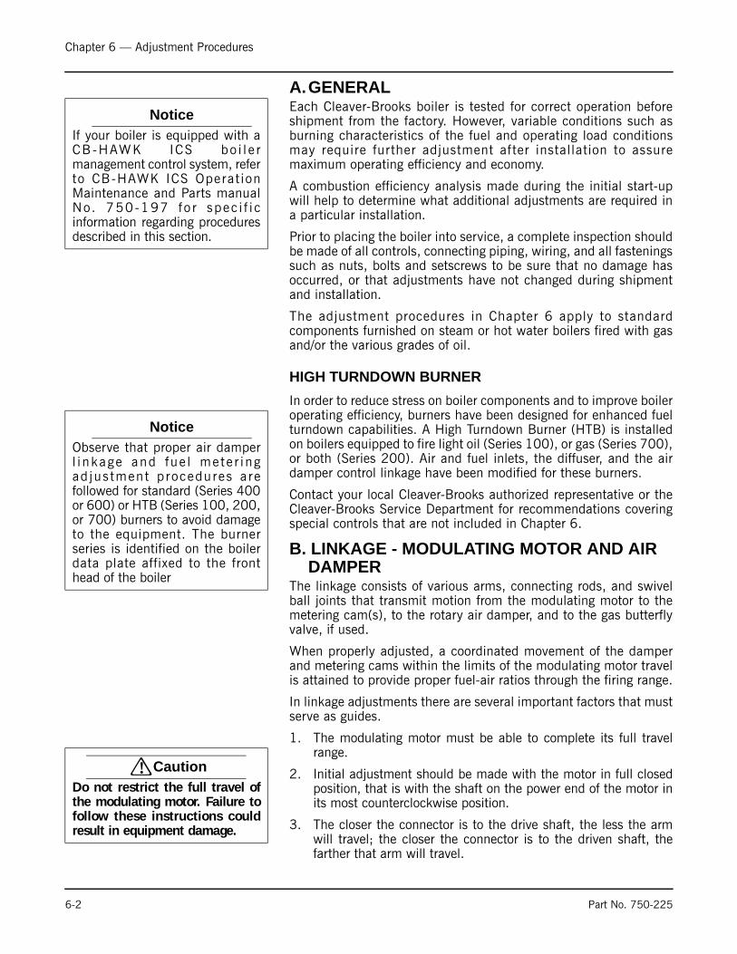
Chapter 6 — Adjustment Procedures
A.GENERALEach Cleaver-Brooks boiler is tested for correct operation beforeshipment from the factory. However, variable conditions such asburning characteristics of the fuel and operating load conditionsmay require further adjustment after installation to assuremaximum operating efficiency and economy.
A combustion efficiency analysis made during the initial start-upwill help to determine what additional adjustments are required ina particular installation.
Prior to placing the boiler into service, a complete inspection shouldbe made of all controls, connecting piping, wiring, and all fasteningssuch as nuts, bolts and setscrews to be sure that no damage hasoccurred, or that adjustments have not changed during shipmentand installation.
The adjustment procedures in Chapter 6 apply to standardcomponents furnished on steam or hot water boilers fired with gasand/or the various grades of oil.
HIGH TURNDOWN BURNER
In order to reduce stress on boiler components and to improve boileroperating efficiency, burners have been designed for enhanced fuelturndown capabilities. A High Turndown Burner (HTB) is installedon boilers equipped to fire light oil (Series 100), or gas (Series 700),or both (Series 200). Air and fuel inlets, the diffuser, and the airdamper control linkage have been modified for these burners.
Contact your local Cleaver-Brooks authorized representative or theCleaver-Brooks Service Department for recommendations coveringspecial controls that are not included in Chapter 6.
B. LINKAGE - MODULATING MOTOR AND AIR DAMPER
The linkage consists of various arms, connecting rods, and swivelball joints that transmit motion from the modulating motor to themetering cam(s), to the rotary air damper, and to the gas butterflyvalve, if used.
When properly adjusted, a coordinated movement of the damperand metering cams within the limits of the modulating motor travelis attained to provide proper fuel-air ratios through the firing range.
In linkage adjustments there are several important factors that mustserve as guides.
1. The modulating motor must be able to complete its full travelrange.
2. Initial adjustment should be made with the motor in full closedposition, that is with the shaft on the power end of the motor inits most counterclockwise position.
3. The closer the connector is to the drive shaft, the less the armwill travel; the closer the connector is to the driven shaft, thefarther that arm will travel.
NoticeIf your boiler is equipped with aCB -HAWK ICS bo i l e rmanagement control system, referto CB-HAWK ICS Operat ionMaintenance and Parts manualNo. 750-197 fo r spec i f i cinformation regarding proceduresdescribed in this section.
NoticeObserve that proper air damperl inkage and fue l mete r ingad jus tment p rocedures arefollowed for standard (Series 400or 600) or HTB (Series 100, 200,or 700) burners to avoid damageto the equipment. The burnerseries is identified on the boilerdata plate affixed to the fronthead of the boiler
! CautionDo not restrict the full travel ofthe modulating motor. Failure tofollow these instructions couldresult in equipment damage.
6-2 Part No. 750-225

Chapter 6 — Adjustment Procedures
4. Over-travel linkage, where used, should not be required in orderto extend its spring to the fullest stretch.
With the modulating motor in the low fire position, the arm on itsshaft should be at an angle of 45° below the horizontal. The drivenarm on the jack shaft should also be 45° below horizontal. Secureboth arms and fit the connecting linkage rod in place between them.Refer to Figure 6-1.
Position the oil and/or gas modulating cams on the jackshaft so thatthe cam follower assembly is between the first and second camadjusting screws (under the first adjusting screw for High TurndownBurners). In this position, fuel delivery is at low fire rate. Tighten theset screws to secure the cams on the jackshaft.
Refer to Figure 6-2. The stop screw in the rotary air damper limitsdamper travel at both closed (low fire) and fully opened (high fire)positions. The screw is provided so that it is possible to tell, even
Figure 6-1 Complete Linkage Assembly - Combination Gas and Oil
45
45
GAS MODULATING CAM
CAM ADJUSTING
SCREW
GAS MODULATING
CAM FOLLOWER
GAS METERING
VALVE
ROTARY AIR
DAMPER
ROD
MODULATING MOTOR
MOTOR
MODULATING
MOTOR ARMSPRING LOADED
BUTTERFLY GAS VALVE ARM
OVERTRAVEL LINKAGE
BUTTERFLY GAS VALVE
ROTARY AIR
DAMPER ARMFUEL OIL
CONTROLLER
NOTICE:
SETTINGS IN DIAGRAM
INDICATE LOW FIRE
SETTING OF LINKAGE.
ROTARY AIR
DAMPER SHAFT
OIL METERING VALVE
OIL MODULATING
CAM FOLLOWER
OIL MODULATING
CAM
CAM
ADJUSTING
SCREW
ROTARY AIR DAMPER
JACKSHAFT ARM
BUTTERFLY
GAS VALVE ROD
60
JACK SHAFT
DRIVING ARM
MODULATING
MOTOR ROD
60
The initial settings on a high turndown burner for the rotary air damper should be 57° and the connecting jackshaft arm should be set at 47 1/2°.
Part No. 750-225 6-3
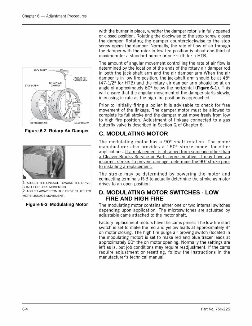
Chapter 6 — Adjustment Procedures
with the burner in place, whether the damper rotor is in fully openedor closed position. Rotating the clockwise to the stop screw closesthe damper. Rotating the damper counterclockwise to the stopscrew opens the damper. Normally, the rate of flow of air throughthe damper with the rotor in low fire position is about one-third ofmaximum for a standard burner or one-sixth for a HTB.
The amount of angular movement controlling the rate of air flow isdetermined by the location of the ends of the rotary air damper rodin both the jack shaft arm and the air damper arm.When the airdamper is in low fire position, the jackshaft arm should be at 45°(47-1/2° for HTB) and the rotary air damper arm should be at anangle of approximately 60° below the horizontal (Figure 6-1). Thiswill ensure that the angular movement of the damper starts slowly,increasing in rate as the high fire position is approached.
Prior to initially firing a boiler it is advisable to check for freemovement of the linkage. The damper motor must be allowed tocomplete its full stroke and the damper must move freely from lowto high fire position. Adjustment of linkage connected to a gasbutterfly valve is described in Section Q of Chapter 6.
C. MODULATING MOTOR The modulating motor has a 90° shaft rotation. The motormanufacturer also provides a 160° stroke model for otherapplications. If a replacement is obtained from someone other thana Cleaver-Brooks Service or Parts representative, it may have anincorrect stroke. To prevent damage, determine the 90° stroke priorto installing a replacement.
The stroke may be determined by powering the motor andconnecting terminals R-B to actually determine the stroke as motordrives to an open position.
D. MODULATING MOTOR SWITCHES - LOW FIRE AND HIGH FIRE
The modulating motor contains either one or two internal switchesdepending upon application. The microswitches are actuated byadjustable cams attached to the motor shaft.
Factory replacement motors have the cams preset. The low fire startswitch is set to make the red and yellow leads at approximately 8°on motor closing. The high fire purge air proving switch (located inthe modulating motor) is set to make red and blue tracer leads atapproximately 60° the on motor opening. Normally the settings areleft as is, but job conditions may require readjustment. If the camsrequire adjustment or resetting, follow the instructions in themanufacturer’s technical manual.
Figure 6-2 Rotary Air Damper
JACK SHAFT
ROTARY AIRDAMPER ARM
ROTARY AIRDAMPERSTOP SCREW
DIFFUSER PLATE DAMPER ARM
Figure 6-3 Modulating Motor
1. ADJUST THE LINKAGE TOWARD THE DRIVE SHAFT FOR LESS MOVEMENT. 2. ADJUST AWAY FROM THE DRIVE SHAFT FORMORE LINKAGE MOVEMENT.
6-4 Part No. 750-225
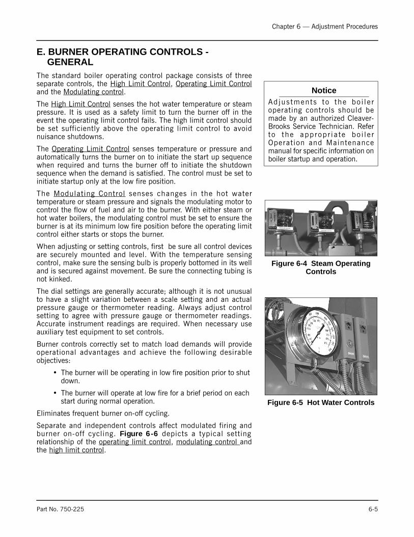
Chapter 6 — Adjustment Procedures
E. BURNER OPERATING CONTROLS -GENERAL
The standard boiler operating control package consists of threeseparate controls, the High Limit Control, Operating Limit Controland the Modulating control.
The High Limit Control senses the hot water temperature or steampressure. It is used as a safety limit to turn the burner off in theevent the operating limit control fails. The high limit control shouldbe set sufficiently above the operating limit control to avoidnuisance shutdowns.
The Operating Limit Control senses temperature or pressure andautomatically turns the burner on to initiate the start up sequencewhen required and turns the burner off to initiate the shutdownsequence when the demand is satisfied. The control must be set toinitiate startup only at the low fire position.
The Modulating Control senses changes in the hot watertemperature or steam pressure and signals the modulating motor tocontrol the flow of fuel and air to the burner. With either steam orhot water boilers, the modulating control must be set to ensure theburner is at its minimum low fire position before the operating limitcontrol either starts or stops the burner.
When adjusting or setting controls, first be sure all control devicesare securely mounted and level. With the temperature sensingcontrol, make sure the sensing bulb is properly bottomed in its welland is secured against movement. Be sure the connecting tubing isnot kinked.
The dial settings are generally accurate; although it is not unusualto have a slight variation between a scale setting and an actualpressure gauge or thermometer reading. Always adjust controlsetting to agree with pressure gauge or thermometer readings.Accurate instrument readings are required. When necessary useauxiliary test equipment to set controls.
Burner controls correctly set to match load demands will provideoperational advantages and achieve the following desirableobjectives:
• The burner will be operating in low fire position prior to shut down.
• The burner will operate at low fire for a brief period on each start during normal operation.
Eliminates frequent burner on-off cycling.
Separate and independent controls affect modulated firing andburner on-off cycling. Figure 6-6 depicts a typical settingrelationship of the operating limit control, modulating control andthe high limit control.
NoticeAd jus tments to the bo i l e roperating controls should bemade by an authorized Cleaver-Brooks Service Technician. Referto the approp r i a te bo i l e rOperat ion and Maintenancemanual for specific information onboiler startup and operation.
Figure 6-4 Steam Operating Controls
Figure 6-5 Hot Water Controls
Part No. 750-225 6-5
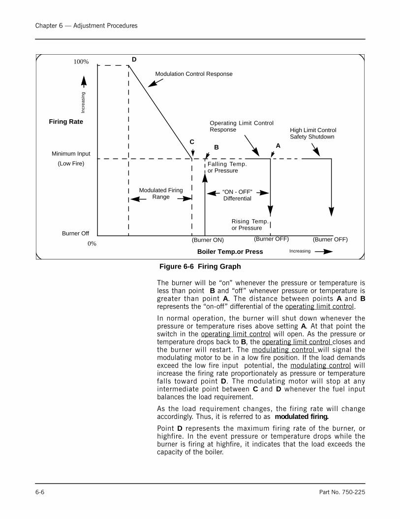
Chapter 6 — Adjustment Procedures
The burner will be “on” whenever the pressure or temperature isless than point B and “off” whenever pressure or temperature isgreater than point A. The distance between points A and Brepresents the “on-off” differential of the operating limit control.
In normal operation, the burner will shut down whenever thepressure or temperature rises above setting A. At that point theswitch in the operating limit control will open. As the pressure ortemperature drops back to B, the operating limit control closes andthe burner will restart. The modulating control will signal themodulating motor to be in a low fire position. If the load demandsexceed the low fire input potential, the modulating control willincrease the firing rate proportionately as pressure or temperaturefalls toward point D. The modulating motor will stop at anyintermediate point between C and D whenever the fuel inputbalances the load requirement.
As the load requirement changes, the firing rate will changeaccordingly. Thus, it is referred to as modulated firing.
Point D represents the maximum firing rate of the burner, orhighfire. In the event pressure or temperature drops while theburner is firing at highfire, it indicates that the load exceeds thecapacity of the boiler.
Figure 6-6 Firing Graph
Modulated Firing Range
Firing Rate
100%
0%
Minimum Input
(Low Fire)
Burner Off
Incr
easi
ng
Falling Temp.or Pressure
“ON - OFF” Differential
Rising Temp.or Pressure
Incr
easi
ng
Increasing
(Burner ON) (Burner OFF) (Burner OFF)
Boiler Temp.or Press
High Limit ControlSafety Shutdown
Operating Limit ControlResponse
Modulation Control Response
D
CB A
6-6 Part No. 750-225
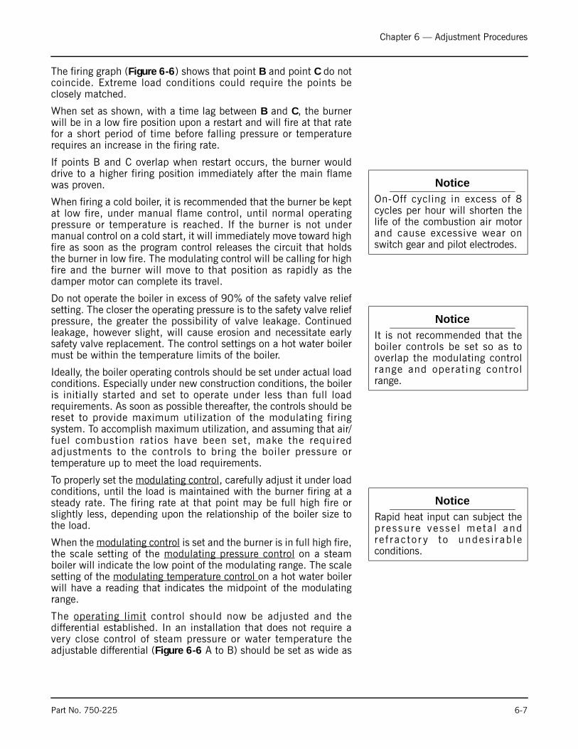
Chapter 6 — Adjustment Procedures
The firing graph (Figure 6-6) shows that point B and point C do notcoincide. Extreme load conditions could require the points beclosely matched.
When set as shown, with a time lag between B and C, the burnerwill be in a low fire position upon a restart and will fire at that ratefor a short period of time before falling pressure or temperaturerequires an increase in the firing rate.
If points B and C overlap when restart occurs, the burner woulddrive to a higher firing position immediately after the main flamewas proven.
When firing a cold boiler, it is recommended that the burner be keptat low fire, under manual flame control, until normal operatingpressure or temperature is reached. If the burner is not undermanual control on a cold start, it will immediately move toward highfire as soon as the program control releases the circuit that holdsthe burner in low fire. The modulating control will be calling for highfire and the burner will move to that position as rapidly as thedamper motor can complete its travel.
Do not operate the boiler in excess of 90% of the safety valve reliefsetting. The closer the operating pressure is to the safety valve reliefpressure, the greater the possibility of valve leakage. Continuedleakage, however slight, will cause erosion and necessitate earlysafety valve replacement. The control settings on a hot water boilermust be within the temperature limits of the boiler.
Ideally, the boiler operating controls should be set under actual loadconditions. Especially under new construction conditions, the boileris initially started and set to operate under less than full loadrequirements. As soon as possible thereafter, the controls should bereset to provide maximum utilization of the modulating firingsystem. To accomplish maximum utilization, and assuming that air/fuel combustion ratios have been set, make the requiredadjustments to the controls to bring the boiler pressure ortemperature up to meet the load requirements.
To properly set the modulating control, carefully adjust it under loadconditions, until the load is maintained with the burner firing at asteady rate. The firing rate at that point may be full high fire orslightly less, depending upon the relationship of the boiler size tothe load.
When the modulating control is set and the burner is in full high fire,the scale setting of the modulating pressure control on a steamboiler will indicate the low point of the modulating range. The scalesetting of the modulating temperature control on a hot water boilerwill have a reading that indicates the midpoint of the modulatingrange.
The operating limit control should now be adjusted and thedifferential established. In an installation that does not require avery close control of steam pressure or water temperature theadjustable differential (Figure 6-6 A to B) should be set as wide as
NoticeOn-Off cycling in excess of 8cycles per hour will shorten thelife of the combustion air motorand cause excessive wear onswitch gear and pilot electrodes.
NoticeIt is not recommended that theboiler controls be set so as tooverlap the modulating controlrange and operating controlrange.
NoticeRapid heat input can subject thep ressu re vesse l meta l andre f rac to r y to undes i rab leconditions.
Part No. 750-225 6-7

Chapter 6 — Adjustment Procedures
conditions permit, since a wide setting will provide less frequentburner cycling.
The high limit control provides a safety factor to shut the burner offin the event the operating limit control should fail. The setting of thecontrol should be sufficiently above the operating limit control toavoid nuisance shutdowns. The setting, however, must be withinthe limits of the safety valve settings and should not exceed 90% ofthe valve setting. The control requires manual resetting after it shutsoff the burner.
In the setting of the controls, consideration must be given to thetime required for a burner restart. Each start, requires a prepurgeperiod, plus the fixed time required for proving the pilot and mainflame. In addition, approximately one-half minute is required for thedamper motor to travel from low to high fire. The time lag may allowpressure or temperature to drop below desirable limits.
F. MODULATING PRESSURE CONTROL (STEAM)
Turn the adjusting screw until the indicator is opposite the low pointof the desired modulating range. Modulated firing will rangebetween the low point and a higher point equal to the modulatingrange of the particular control. In 0-15 psi controls the range is 1/2 lb; in 5-150 psi controls the range is 5 lbs; in 10-300 psi controlsthe range is 12 lbs.
G. OPERATING LIMIT PRESSURE CONTROL (STEAM)
Set the “cut-out” (burner-off) pressure on the main scale using thelarge adjusting screw. Set the differential on the short scale byturning the small adjusting screw until the indicator points to thedesired difference between cut-out and cut-in pressures. The “cut-in” (burner-on) pressure is the cut-out pressure MINUS thedifferential. The cut-out pressure should not exceed 90% of thesafety valve setting.
H. HIGH LIMIT PRESSURE CONTROL (STEAM) Set “cut-out” (burner off) pressure on the main scale using theadjusting screw. The control will break a circuit when pressurereaches this point. The setting should be sufficiently above theoperating limit pressure control to avoid shutdowns, and preferablynot exceed 90% of safety valve setting. The control requires manualresetting after tripping on a pressure increase. To reset, allowpressure to return to normal and then press the reset button.
I. MODULATING TEMPERATURE CONTROL (HOT WATER)
Turn the knob on the front of the case until the pointer indicates thedesired setpoint temperature. The desired set point is the centerpoint of a proportional range. The control has a 3 to 30° differentialand may be adjusted to vary the temperature range within which
Figure 6-7 Steam Operating Controls
! CautionTo prevent burner shutdown atother than low-fire sett ing,adjust the modulating pressurecontrol to modulate to low fireBEFORE the operating limitpressure control shuts off theburner. Failure to follow theseinstructions could result indamage to the equipment
6-8 Part No. 750-225

Chapter 6 — Adjustment Procedures
modulating action is desired. With the cover off, turn theadjustment wheel until pointer indicates desired range.
J. OPERATING LIMIT TEMPERATURE CONTROL (HOT WATER)
Set “cut-out” (burner off) temperature on the scale by inserting ascrewdriver through the cover opening to engage the slotted headadjusting screw. The “cut-in” (burner on) temperature is the cut-outtemperature MINUS the differential. The differential is adjustedfrom 5 to 30° F.
K. HIGH LIMIT TEMPERATURE CONTROL (HOT WATER)
Set the “cut-out” (burner off) temperature on scale using theadjusting screw. The control will break the circuit and lock out on arise in water temperature above the setting. The setting should besufficiently above the operating limit temperature to avoidunnecessary shutdowns. On a 30 psig hot water boiler, the settingis not to exceed 240° F. The control requires manual resetting aftertripping on a temperature increase. To reset, allow the watertemperature to drop below the cut-out setting less differential, andthen press the manual reset button.
L. LOW WATER CUTOFF DEVICES (STEAM AND HOT WATER)
No adjustment is required since LWCO controls are preset by theoriginal manufacturer. However, if the water level is not maintainedas shown in Chapter 3, Figure 3-2, inspect the devices immediatelyand replace as required.
M. COMBUSTION AIR PROVING SWITCH Air pressure against the diaphragm actuates the switch which,when made, completes a circuit to prove the presence ofcombustion air. Since the pressure of the combustion air is at itsminimum value when the damper is full open, the switch should beadjusted under that situation. It should be set slightly below theminimum pressure, but not too close to that point to cause nuisanceshutdowns.
Figure 6-8 Hot Water Controls
1. MODULATING TEMPERATURE CONTROL2. OPERATING TEMPERATURE CONTROL3. HIGH LIMIT TEMPERATURE CONTROL
! CautionTo prevent burner shutdown atother than low-fire setting, adjustthe modulating pressure controlto modulate to low fire BEFOREthe operating limit pressurecontrol shuts off the burner.Fa i lu re to f o l l ow theseinstructions could result indamage to the equipment
Part No. 750-225 6-9
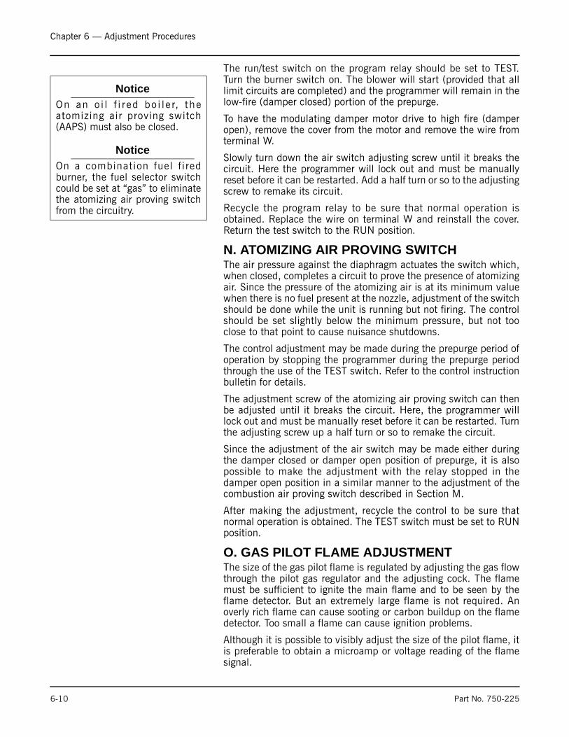
Chapter 6 — Adjustment Procedures
The run/test switch on the program relay should be set to TEST.Turn the burner switch on. The blower will start (provided that alllimit circuits are completed) and the programmer will remain in thelow-fire (damper closed) portion of the prepurge.
To have the modulating damper motor drive to high fire (damperopen), remove the cover from the motor and remove the wire fromterminal W.
Slowly turn down the air switch adjusting screw until it breaks thecircuit. Here the programmer will lock out and must be manuallyreset before it can be restarted. Add a half turn or so to the adjustingscrew to remake its circuit.
Recycle the program relay to be sure that normal operation isobtained. Replace the wire on terminal W and reinstall the cover.Return the test switch to the RUN position.
N. ATOMIZING AIR PROVING SWITCH The air pressure against the diaphragm actuates the switch which,when closed, completes a circuit to prove the presence of atomizingair. Since the pressure of the atomizing air is at its minimum valuewhen there is no fuel present at the nozzle, adjustment of the switchshould be done while the unit is running but not firing. The controlshould be set slightly below the minimum pressure, but not tooclose to that point to cause nuisance shutdowns.
The control adjustment may be made during the prepurge period ofoperation by stopping the programmer during the prepurge periodthrough the use of the TEST switch. Refer to the control instructionbulletin for details.
The adjustment screw of the atomizing air proving switch can thenbe adjusted until it breaks the circuit. Here, the programmer willlock out and must be manually reset before it can be restarted. Turnthe adjusting screw up a half turn or so to remake the circuit.
Since the adjustment of the air switch may be made either duringthe damper closed or damper open position of prepurge, it is alsopossible to make the adjustment with the relay stopped in thedamper open position in a similar manner to the adjustment of thecombustion air proving switch described in Section M.
After making the adjustment, recycle the control to be sure thatnormal operation is obtained. The TEST switch must be set to RUNposition.
O. GAS PILOT FLAME ADJUSTMENTThe size of the gas pilot flame is regulated by adjusting the gas flowthrough the pilot gas regulator and the adjusting cock. The flamemust be sufficient to ignite the main flame and to be seen by theflame detector. But an extremely large flame is not required. Anoverly rich flame can cause sooting or carbon buildup on the flamedetector. Too small a flame can cause ignition problems.
Although it is possible to visibly adjust the size of the pilot flame, itis preferable to obtain a microamp or voltage reading of the flamesignal.
NoticeOn an o i l f i r ed bo i l e r, theatomizing air proving switch(AAPS) must also be closed.
NoticeOn a combination fuel f i redburner, the fuel selector switchcould be set at “gas” to eliminatethe atomizing air proving switchfrom the circuitry.
6-10 Part No. 750-225
Chapter 6 — Adjustment Procedures
The correct voltage or microamp readings can be found in theinformation supplied with the flame safeguard system.
The program relay used may be of the type that provides messageinformation that includes a constant flame signal of dc voltage. Inthis case a separate dc voltmeter is not required.
To Measure and Adjust Pilot:
1. When making a pilot adjustment, turn the manual-automaticswitch to “manual” and the manual flame control to “close.”Open both the pilot cutoff cock and the pilot adjusting cock. Themain gas cock should remain closed.
The regulator in the pilot line, if provided, is to reduce the gas pressure to suit the pilot's requirement of between 5 to 10" WC. Regulator adjustment is not critical; however, with a lower pressure the final adjustment of the pilot flame with adjusting cock is less sensitive.
2. Connect the micro-ammeter as outlined earlier.
3. Turn the burner switch on. Let the burner go through the normalprepurge cycle. When the ignition trial period is signaled, set thetest switch to the TEST position to stop the sequence.
4. If the pilot flame is not established within 10 seconds, turn offthe burner switch. Repeat the lighting attempt.
5. When the pilot flame is established, and with the pilot adjustingcock wide open, remove the flame detector from the burnerplate. The pilot flame can then be observed through thisopening.
6. To make the final adjustment, slowly close the gas pilotadjusting cock until the flame can no longer be seen through thesight tube. Then slowly open the cock until a flame providingfull sight tube coverage is observed.
The adjustment must be accomplished within the time limit of the safety switch or approximately 30 seconds after the detector is removed. If the control shuts down, manually reset it. Replace the detector and repeat the process from step 5.
7. When a suitable flame as indicated in paragraph 6 is obtained,replace the detector. Observe the reading on the micro-ammeter. The reading should be between 2-1/4 and 5microamps when using a lead sulfide detector and a standardamplifier. See the flame signal table in the manufacturer'sbulletin for values of other combinations.
The flame signal indicated on the annunciator type relay should not be less than 10 Vdc, and may be as high as 20 Vdc or greater.
The reading must be steady. If the reading fluctuates, recheck the adjustment. Be sure that the flame detector is properly seated and that the lens is clean.
8. Return the test switch to the RUN position.
9. If main flame has not been previously established, proceed to doso in accordance with instructions elsewhere in the manual.
NoticeOn an initial starting attempt,portions of the fuel lines may beempty and require “bleeding”time. It is better to accomplishthis with repeated short lightingtrial periods with interveningpurge pe r iods than to r i skprolonged fuel introduction. If thepilot does not light after severalattempts, check all componentsof the pilot system
! WarningWear a protective shield orsuitable glasses and keep eyessufficiently away from thesight tube opening to avoidserious personal injury ordeath. Never remove theflame detector while the mainburner is firing. Failure tofollow these instructions couldresult in serious personalinjury or death
! WarningWhen checking the pilot flame,be aware the e l ec t rode i senergized. Failure to followthese instructions could result inserious personal injury
Part No. 750-225 6-11

Chapter 6 — Adjustment Procedures
10. The reading of the main flame signal should also be checked.Observe the flame signal for pilot alone, pilot and main burnerflame together and the main burner flame at high, low, andintermediate firing rate positions. Readings should be steadyand in the range indicated in paragraph 7. If there are anydeviations, refer to the trouble shooting section in the technicalbulletin.
P. GAS PRESSURE AND FLOW INFORMATIONBecause of variables in both the properties of gas and the supplysystem, it will be necessary to regulate the pressure of the gas to alevel that produces a steady, dependable flame that yields highestcombustion efficiency at rated performance yet prevents overfiring.Once the optimum pressure has been established, it should berecorded and periodic checks made to verify that the regulator isholding the pressure at this level. Occasional modification in fuelcomposition or pressure by the supplier may, at times, requirereadjustment to return the burner to peak efficiency. Since the gaspressure regulator itself is usually furnished by others, detailedadjustment instructions and adjusting procedures recommended bythe manufacturer should be followed.
Table 6-1 Minimum Required Gas Pressure at Entrance to
Standard, FM and IRI Gas Trains (Downstream of Gas Pressure
Regulator)
Pressure
The gas supplied must provide not only the quantity of gasdemanded by the unit, but must also be at a pressure high enoughto overcome the pressure-loss due to the frictional resistanceimposed by the burner system and the control valves.
The pressure required at the entrance to the burner gas train forrated boiler output is termed “net regulated pressure.” The gaspressure regulator must be adjusted to achieve the pressure toassure full input.
The pressure requirement varies with boiler size, altitude, and typeof gas train. Refer to Table 6-1 for pressure require-ments.
The pressures listed are based on 1000 Btu/cu-ft natural gas atelevations up to 700 feet above sea level. For installation at higheraltitudes, multiply the selected pressure by the proper factor fromTable 6-2.
BOILER HPSTD Pipe Size
(Inches)
Pressure Requires (“WC)
125 2-1/2 9
150 2-1/2 11.5
200 2-1/2 16.5
250 3 28
300 3 39
350 3 52
400 4 24
500 4 38
600 4 48
700 4 64
800 4 85
6-12 Part No. 750-225
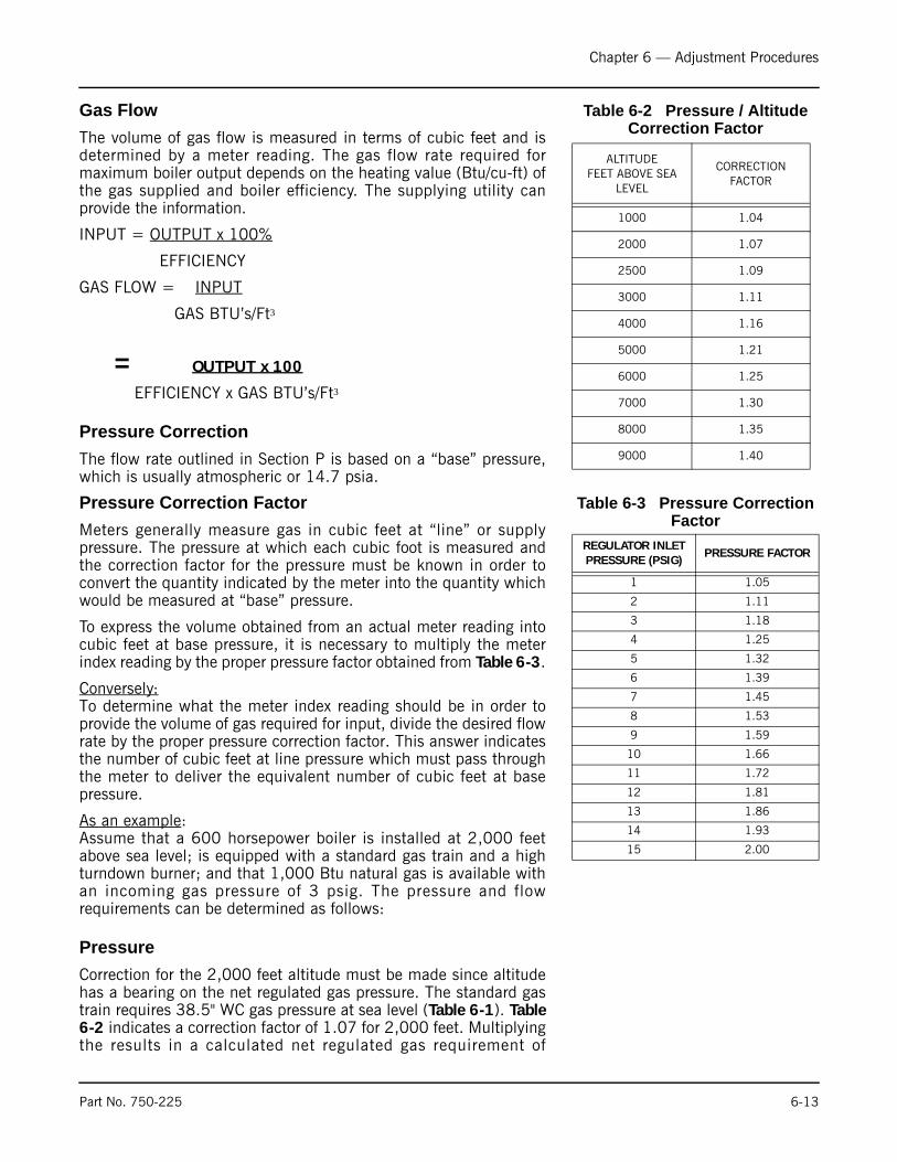
Chapter 6 — Adjustment Procedures
Table 6-2 Pressure / Altitude Correction Factor
Gas Flow
The volume of gas flow is measured in terms of cubic feet and isdetermined by a meter reading. The gas flow rate required formaximum boiler output depends on the heating value (Btu/cu-ft) ofthe gas supplied and boiler efficiency. The supplying utility canprovide the information.
INPUT = OUTPUT x 100%
EFFICIENCY
GAS FLOW = INPUT
GAS BTU’s/Ft3
= OUTPUT x 100
EFFICIENCY x GAS BTU’s/Ft3
Pressure Correction
The flow rate outlined in Section P is based on a “base” pressure,which is usually atmospheric or 14.7 psia.
Table 6-3 Pressure Correction Factor
Pressure Correction Factor
Meters generally measure gas in cubic feet at “line” or supplypressure. The pressure at which each cubic foot is measured andthe correction factor for the pressure must be known in order toconvert the quantity indicated by the meter into the quantity whichwould be measured at “base” pressure.
To express the volume obtained from an actual meter reading intocubic feet at base pressure, it is necessary to multiply the meterindex reading by the proper pressure factor obtained from Table 6-3.
Conversely: To determine what the meter index reading should be in order toprovide the volume of gas required for input, divide the desired flowrate by the proper pressure correction factor. This answer indicatesthe number of cubic feet at line pressure which must pass throughthe meter to deliver the equivalent number of cubic feet at basepressure.
As an example:Assume that a 600 horsepower boiler is installed at 2,000 feetabove sea level; is equipped with a standard gas train and a highturndown burner; and that 1,000 Btu natural gas is available withan incoming gas pressure of 3 psig. The pressure and flowrequirements can be determined as follows:
Pressure
Correction for the 2,000 feet altitude must be made since altitudehas a bearing on the net regulated gas pressure. The standard gastrain requires 38.5" WC gas pressure at sea level (Table 6-1). Table6-2 indicates a correction factor of 1.07 for 2,000 feet. Multiplyingthe results in a calculated net regulated gas requirement of
ALTITUDEFEET ABOVE SEA
LEVEL
CORRECTION FACTOR
1000 1.04
2000 1.07
2500 1.09
3000 1.11
4000 1.16
5000 1.21
6000 1.25
7000 1.30
8000 1.35
9000 1.40
REGULATOR INLETPRESSURE (PSIG)
PRESSURE FACTOR
1 1.05
2 1.11
3 1.18
4 1.25
5 1.32
6 1.39
7 1.45
8 1.53
9 1.59
10 1.66
11 1.72
12 1.81
13 1.86
14 1.93
15 2.00
Part No. 750-225 6-13
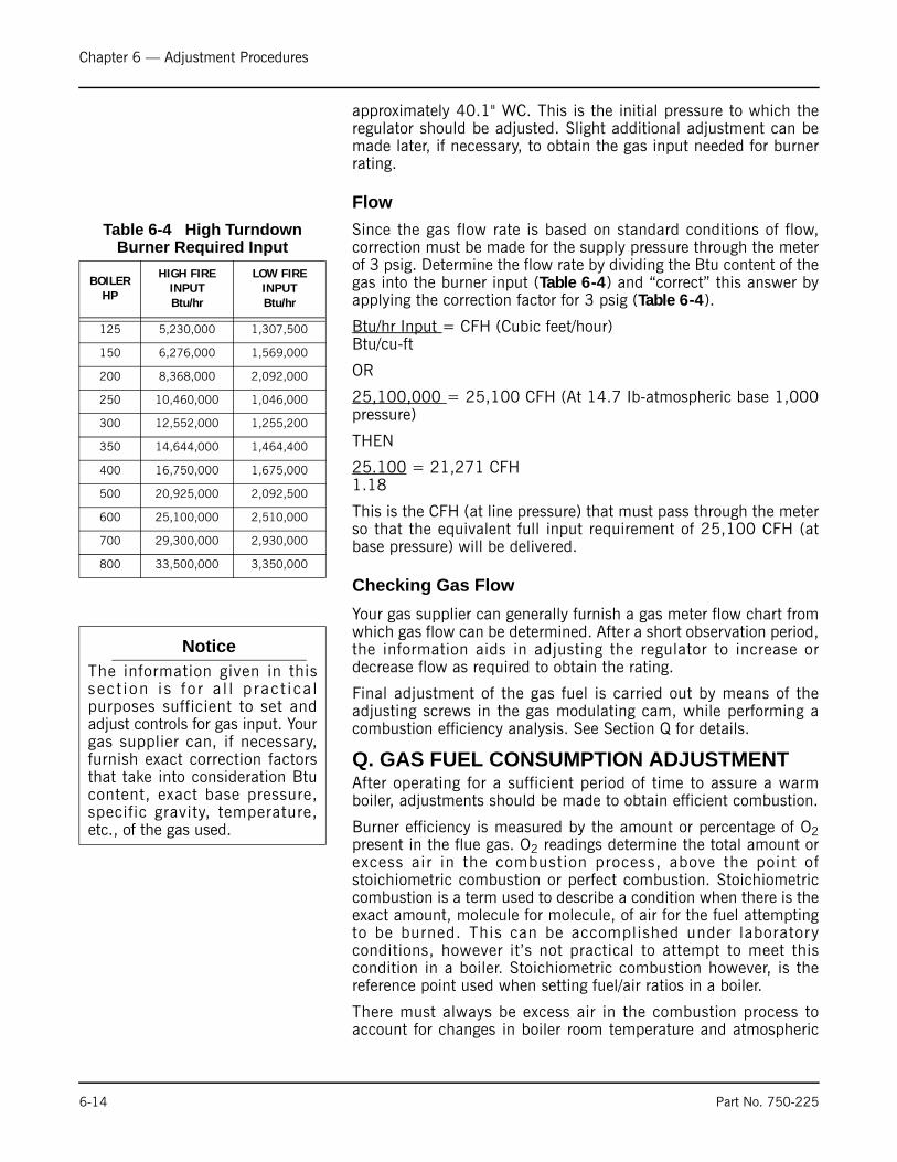
Chapter 6 — Adjustment Procedures
approximately 40.1" WC. This is the initial pressure to which theregulator should be adjusted. Slight additional adjustment can bemade later, if necessary, to obtain the gas input needed for burnerrating.
Flow
Table 6-4 High Turndown Burner Required Input
Since the gas flow rate is based on standard conditions of flow,correction must be made for the supply pressure through the meterof 3 psig. Determine the flow rate by dividing the Btu content of thegas into the burner input (Table 6-4) and “correct” this answer byapplying the correction factor for 3 psig (Table 6-4).
Btu/hr Input = CFH (Cubic feet/hour) Btu/cu-ft
OR
25,100,000 = 25,100 CFH (At 14.7 Ib-atmospheric base 1,000pressure)
THEN
25.100 = 21,271 CFH 1.18
This is the CFH (at line pressure) that must pass through the meterso that the equivalent full input requirement of 25,100 CFH (atbase pressure) will be delivered.
Checking Gas Flow
Your gas supplier can generally furnish a gas meter flow chart fromwhich gas flow can be determined. After a short observation period,the information aids in adjusting the regulator to increase ordecrease flow as required to obtain the rating.
Final adjustment of the gas fuel is carried out by means of theadjusting screws in the gas modulating cam, while performing acombustion efficiency analysis. See Section Q for details.
Q. GAS FUEL CONSUMPTION ADJUSTMENTAfter operating for a sufficient period of time to assure a warmboiler, adjustments should be made to obtain efficient combustion.
Burner efficiency is measured by the amount or percentage of O2present in the flue gas. O2 readings determine the total amount orexcess air in the combustion process, above the point ofstoichiometric combustion or perfect combustion. Stoichiometriccombustion is a term used to describe a condition when there is theexact amount, molecule for molecule, of air for the fuel attemptingto be burned. This can be accomplished under laboratoryconditions, however it’s not practical to attempt to meet thiscondition in a boiler. Stoichiometric combustion however, is thereference point used when setting fuel/air ratios in a boiler.
There must always be excess air in the combustion process toaccount for changes in boiler room temperature and atmospheric
BOILER HP
HIGH FIRE INPUTBtu/hr
LOW FIRE INPUTBtu/hr
125 5,230,000 1,307,500
150 6,276,000 1,569,000
200 8,368,000 2,092,000
250 10,460,000 1,046,000
300 12,552,000 1,255,200
350 14,644,000 1,464,400
400 16,750,000 1,675,000
500 20,925,000 2,092,500
600 25,100,000 2,510,000
700 29,300,000 2,930,000
800 33,500,000 3,350,000
NoticeThe information given in thissec t i on i s f o r a l l p rac t i ca lpurposes sufficient to set andadjust controls for gas input. Yourgas supplier can, if necessary,furnish exact correction factorsthat take into consideration Btucontent, exact base pressure,specific gravity, temperature,etc., of the gas used.
6-14 Part No. 750-225
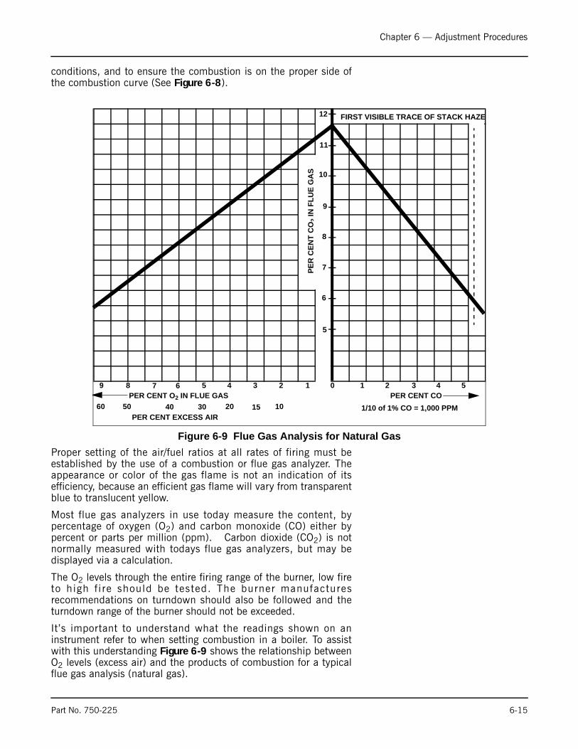
Chapter 6 — Adjustment Procedures
conditions, and to ensure the combustion is on the proper side ofthe combustion curve (See Figure 6-8).
Proper setting of the air/fuel ratios at all rates of firing must beestablished by the use of a combustion or flue gas analyzer. Theappearance or color of the gas flame is not an indication of itsefficiency, because an efficient gas flame will vary from transparentblue to translucent yellow.
Most flue gas analyzers in use today measure the content, bypercentage of oxygen (O2) and carbon monoxide (CO) either bypercent or parts per million (ppm). Carbon dioxide (CO2) is notnormally measured with todays flue gas analyzers, but may bedisplayed via a calculation.
The O2 levels through the entire firing range of the burner, low fireto high f i re should be tested. The burner manufacturesrecommendations on turndown should also be followed and theturndown range of the burner should not be exceeded.
It’s important to understand what the readings shown on aninstrument refer to when setting combustion in a boiler. To assistwith this understanding Figure 6-9 shows the relationship betweenO2 levels (excess air) and the products of combustion for a typicalflue gas analysis (natural gas).
Figure 6-9 Flue Gas Analysis for Natural Gas
PER CENT O2 IN FLUE GAS PER CENT CO
PER CENT EXCESS AIR102030405060
5
6
7
8
9
10
11
12
11 22 33 44 556789 0
PE
R C
EN
T C
O2
IN F
LU
E G
AS
FIRST VISIBLE TRACE OF STACK HAZE
1/10 of 1% CO = 1,000 PPM15
Part No. 750-225 6-15

Chapter 6 — Adjustment Procedures
One of the products of combustion is CO2 (Carbon Dioxide). This isshown in percentage.
Another product of combustion is CO (carbon monoxide) and isshown in both percentage and parts per million (ppm). Themaximum CO level standardly allowed is less than 400 ppm.However, this may change subject to local regulations.
The percent O2 recorded on an instrument equates to percentexcess air, I.E. 3% O2 is approximately 15% excess air and 4% O2is approximately 20% excess air. The exact percentage of excess airis a mathematical calculation based on an ultimate fuel analysis ofthe fuel being fired.
It is generally recommended that O2 readings of between 3% to 4%be attained with less than 400 ppm CO, at high fire.
Using information from Section P of Chapter 6, determine thestandard conditions of gas pressure and flow for the size boiler andthe gas train on it. Calculate the actual pressure and flow throughthe use of correction factors that compensate for incoming gaspressure and altitude.
Basically, gas adjustments are made with a gas pressure regulator,which controls the pressure and with the butterfly gas valve (Figure6-10) which directly controls the rate of flow.
In initially setting the linkage, back off the low fire stop screw on thebutterfly valve so that the valve is closed. Then run the screw out totouch the arm, and give it two complete turns. Adjust theconnecting rod so that the override tension is released and so thatthe arm is now just touching the stop screw. Tighten the locknutson all ball joints. See Figure 6-10.
The low fire setting should be regarded as tentative until the propergas pressure for high fire operation is established.
To reach the high fire rate, turn the manual flame control switchtoward “OPEN” in minor increments while monitoring combustionfor overly rich or lean conditions.
At high fire, the gas butterfly valve should be open as wide asindicated by the slot on the end of the shaft. Set and lock the highfire stop screw so that it is just touching the valve arm.
Determine the actual gas flow from a meter reading. (See section Pof Chapter 6.) With the butterfly valve open and with regulated gaspressure set at the calculated pressure, the actual flow rate shouldbe close to the required input. If corrections are necessary, increaseor decrease the gas pressure by adjusting the gas pressureregulator, following the manufacturer's directions for regulatoradjustment.
When proper gas flow is obtained, take a flue gas reading. The O2should be between 3% and 4% at high fire.
If the fuel input is correct, but the O2 values do not fall within thisrange, the air damper travel may need to be adjusted. Adjustmentof the air damper linkage is described in Section B of Chapter 6.
Figure 6-10 Butterfly Gas Valve
TO FOLLOWER OFGAS MODULATING CAM
HIGHFIRE
LOWFIRE
BUTTERFLY GASVALVE ROD
OVERRIDESPRINGS BUTTERFLY GAS
VALVE ARM
LOW FIRESTOP SCREW
HIGH FIRESTOP SCREW
6-16 Part No. 750-225

Chapter 6 — Adjustment Procedures
With the high-fire air/fuel ratio established, the gas pressureregulator needs no further adjusting.
After being certain that the air control damper and its linkage arecorrectly adjusted to provide the proper amount of secondary air,and after adjusting the gas pressure regulator, final adjustment canbe made, if necessary, to the gas modulating cam to obtain aconstant air/fuel ratio throughout the entire firing range.
Since the input of combustion air is ordinarily fixed at any givenpoint in the modulating cycle, the flue gas reading is determined byvarying the input of gas fuel at that setting. The adjustment is madeto the metering cam by means of adjusting screws, which are turnedoutward (counterclockwise from the hex-socket end) to increase theflow of fuel, and inward (clockwise from the hex-socket end) todecrease it. Flow rate is highest when the cam follower assembly isclosest to jackshaft. See Figure 6-11.
Through the manual flame control switch, position the cam so thatthe adjusting screw adjacent to the end or high fire screw contactsthe cam follower. Perform a combustion analysis at this point. If anadjustment is necessary, turn the adjustment screw accordingly toincrease or decrease fuel flow. Take a combustion reading to verifyinput. Repeat as necessary until the desired flow is obtained.Repeat the process, stopping at each adjusting screw, until the lowfire adjusting screw is reached.
Standard Burner Low Fire Adjustment
The fuel input should be adjusted using the low fire cam screw, toapproximately 25% of that at high fire (Table 6-3). At low fire theO2 flue gas reading should be between 6-7%.
It may be necessary to readjust the setting of the low fire stop screwto obtain the proper air/fuel ratio at the low fire rate. To ensure thatthe low fire position of the gas butterfly valve is always the same,allow one turn of the stop screw for overtravel.
If the air damper needs to be adjusted in order to provide the correctlow fire air/fuel ratio, combustion must be rechecked at higher firingrates and adjusted as required.
If all cam screws are properly adjusted, none will deviate from thegeneral overall contour of the cam face.
Figure 6-11 Fuel Modulating Cam
LOW FIRE
HIGH FIRE
ADJUSTINGSCREWS
AND DOGS
DECREASEFLOW
INCREASEFLOW
CAM FOLLOWERASSEMBLY
NoticeDo not use any lubricant on theadjusting setscrews. The setscrews have a nylon lockinginsert intended to provide lockingto rque and res i s tance toloosening and a lubricant coulddamage equipment.
Part No. 750-225 6-17

Chapter 6 — Adjustment Procedures
High Turndown Burner Low Fire Adjustment
The fuel input should be adjusted using the low fire cam screw, toapproximately 10% of that at high fire (Table 6-4). At low fire theO2 flue gas reading should be between 9.5-11%.
It may be necessary to readjust the setting of the low fire stop screwin order to obtain the proper air/fuel ratio at low fire. To ensure thatthe low fire position of the gas butterfly valve is always the same,allow a half turn of the stop screw for overtravel.
If the air damper must be reset to meet the low fire air/fuelrequirements. combustion at higher firing rates must be rechecked.
The second cam adjusting screw may need to be adjusted in orderto maintain a smooth cam profile. If all screws are properlyadjusted, none will deviate from the general overall contour of thecam face.
R. LOW-GAS-PRESSURE SWITCHAdjust the scale setting to slightly below the normal burningpressure. The control circuit will be broken when pressure fallsbelow this point. Since gas line distribution pressure may decreaseunder some conditions, shutdowns may result if the setting is tooclose to normal. However, regulations require that the setting maynot be less than 50% of the rated pressure downstream of theregulator.
Manual resetting is necessary after a pressure drop. Press the resetlever after pressure is restored. Be sure that the switch equippedcontrol is level.
S. HIGH-GAS-PRESSURE SWITCHAdjust the scale setting to slightly above the normal burningpressure. The control circuit will be broken when pressure exceedsthe normal operating pressure. Unnecessary shutdowns may resultif the setting is too close to normal; however, regulations requirethat the setting may not be greater than 150% of rated pressure.
Manual resetting is necessary after a pressure rise. Press the resetlever after pressure falls. Be sure that the switch equipped controlis level.
T. FUEL OIL PRESSURE AND TEMPERATURE - GENERAL
Variations in burning characteristics of the fuel oil may occasionallyrequire adjustments to assure highest combustion efficiency. Thehandling and burning characteristics may vary from one delivery ofoil to another. Therefore, it is recommended that the oil system beinspected from time to time to verify that pressures and viscosity areat the proper operating levels.
Because of variation in oils, including chemical content, source,blends, and viscosity characteristics, the temperatures andpressures listed in Chapter 5, and mentioned in the adjusting of thecontrols in the following paragraphs, will vary and thus may be
Figure 6-12 Gas Train Pressure Switches
1 3
2
1. HIGH GAS PRESSURE SWITCH2. LOW GAS PRESSURE SWITCH3. MAIN GAS VALVES
6-18 Part No. 750-225
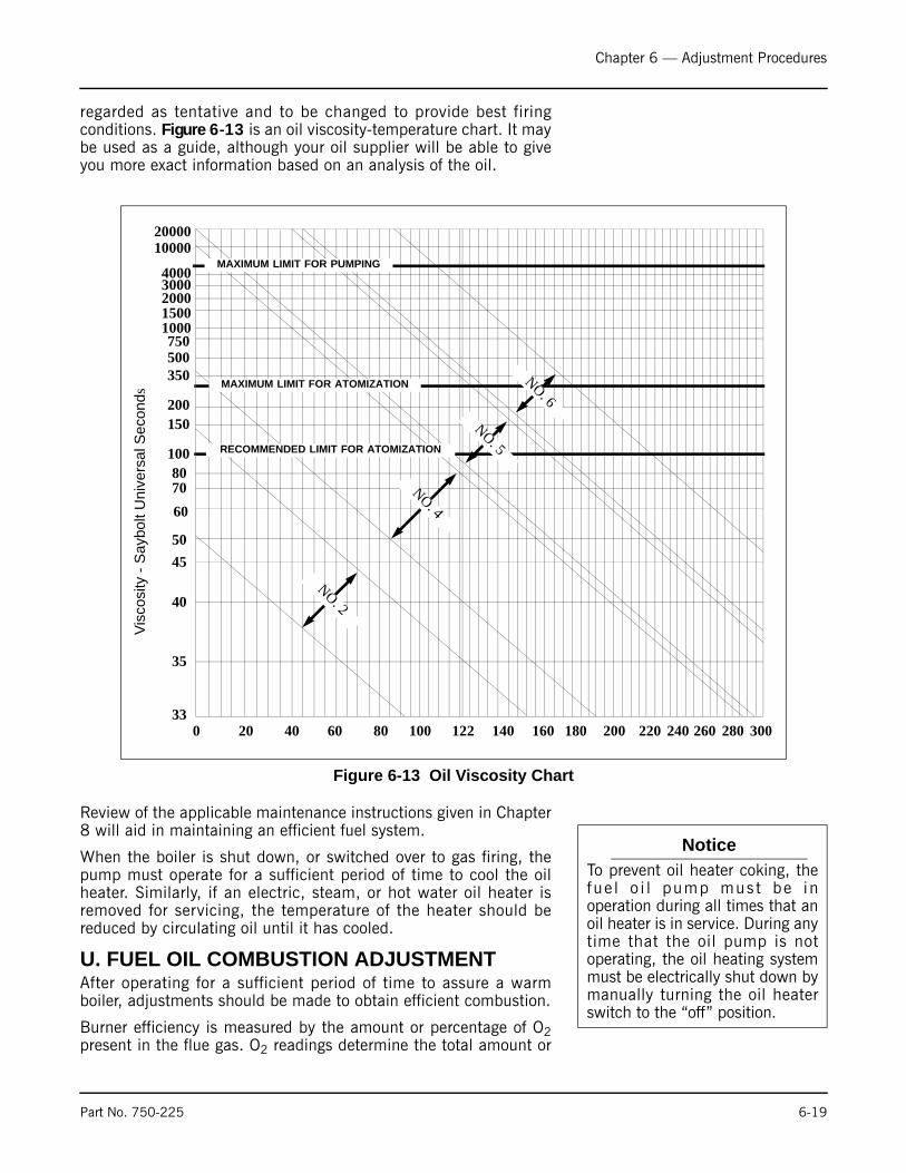
Chapter 6 — Adjustment Procedures
regarded as tentative and to be changed to provide best firingconditions. Figure 6-13 is an oil viscosity-temperature chart. It maybe used as a guide, although your oil supplier will be able to giveyou more exact information based on an analysis of the oil.
Review of the applicable maintenance instructions given in Chapter8 will aid in maintaining an efficient fuel system.
When the boiler is shut down, or switched over to gas firing, thepump must operate for a sufficient period of time to cool the oilheater. Similarly, if an electric, steam, or hot water oil heater isremoved for servicing, the temperature of the heater should bereduced by circulating oil until it has cooled.
U. FUEL OIL COMBUSTION ADJUSTMENTAfter operating for a sufficient period of time to assure a warmboiler, adjustments should be made to obtain efficient combustion.
Burner efficiency is measured by the amount or percentage of O2present in the flue gas. O2 readings determine the total amount or
Figure 6-13 Oil Viscosity Chart
33
35
40
4550
607080
100
150200
350500750
10001500200030004000
1000020000
0 20 40 60 80 100 122 140 160 180 200 220 240 260 280 300
MAXIMUM LIMIT FOR PUMPING
MAXIMUM LIMIT FOR ATOMIZATION
RECOMMENDED LIMIT FOR ATOMIZATION
NO. 2
NO. 4
NO. 5
NO. 6
Visc
osity
- S
aybo
lt U
nive
rsal
Sec
onds
NoticeTo prevent oil heater coking, thefue l o i l pump mus t be inoperation during all times that anoil heater is in service. During anytime that the oil pump is notoperating, the oil heating systemmust be electrically shut down bymanually turning the oil heaterswitch to the “off” position.
Part No. 750-225 6-19

Chapter 6 — Adjustment Procedures
excess air in the combustion process, above the point ofstoichiometric combustion or perfect combustion. Stoichiometriccombustion however, is the reference point used when setting fuel/air ratios in a boiler.
There must always be excess air in the combustion process toaccount for changes in boiler room conditions and to ensure thecombustion is on the proper side of the combustion curve (SeeFigure 6-9).
Proper setting of the air/fuel ratios at all rates of firing must beestablished by the use of a combustion gas analyzer. Efficientcombustion cannot be solely judged by flame condition or color,although they may be used in making approximate settings.Combustion settings should be done so that there is a bright sharpflame with no visible haze.
Figure 6-14 Electrode Setting - Oil Pilot
1/4Ó
3/16Ó 3/16Ó
Figure 6-15 Burner Drawer with Gas Pilot
6-20 Part No. 750-225
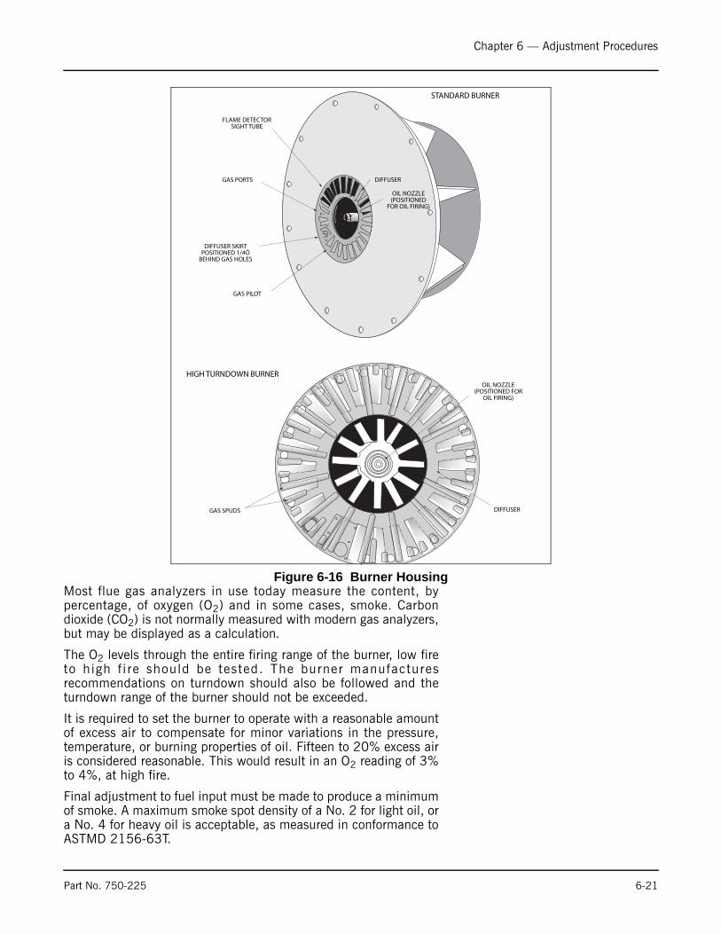
Chapter 6 — Adjustment Procedures
Most flue gas analyzers in use today measure the content, bypercentage, of oxygen (O2) and in some cases, smoke. Carbondioxide (CO2) is not normally measured with modern gas analyzers,but may be displayed as a calculation.
The O2 levels through the entire firing range of the burner, low fireto high f i re should be tested. The burner manufacturesrecommendations on turndown should also be followed and theturndown range of the burner should not be exceeded.
It is required to set the burner to operate with a reasonable amountof excess air to compensate for minor variations in the pressure,temperature, or burning properties of oil. Fifteen to 20% excess airis considered reasonable. This would result in an O2 reading of 3%to 4%, at high fire.
Final adjustment to fuel input must be made to produce a minimumof smoke. A maximum smoke spot density of a No. 2 for light oil, ora No. 4 for heavy oil is acceptable, as measured in conformance toASTMD 2156-63T.
Figure 6-16 Burner Housing
STANDARD BURNER
FLAME DETECTORSIGHT TUBE
GAS PORTS
DIFFUSER SKIRTPOSITIONED 1/4Ó
BEHIND GAS HOLES
GAS PILOT
OIL NOZZLE(POSITIONED
FOR OIL FIRING)
DIFFUSER
HIGH TURNDOWN BURNEROIL NOZZLE
(POSITIONED FOROIL FIRING)
DIFFUSERGAS SPUDS
Part No. 750-225 6-21

Chapter 6 — Adjustment Procedures
Through the use of the manual flame control, slowly bring the unitto high fire by stages while monitoring combustion for overly rich orlean conditions. At the high fire position, the air damper should befully opened and the air and oil pressure readings should be on theorder of the readings given in Chapter 5.
Take a flue gas analysis reading. If necessary, adjust the fuel oilcontroller to increase or decrease oil pressure. Adjustments to thepressure should be done before attempting to adjust the screws inthe metering cam. Ideally, the cam profile spring should be as closeto the cam casting as practical. It is more desirable to lower the oilpressure to reduce flow, if necessary, than to extend the adjustingscrews to an extreme position in an effort to cut back flow.
After being certain that the air control damper and its linkage areoperating properly, final adjustment can be made, if necessary, tothe oil modulating cam to obtain a constant fuel/air ratio throughthe entire firing range.
Since the input of combustion air is ordinarily fixed at any givenpoint in the modulating cycle, the flue gas reading is determined byvarying the input of fuel at that setting. The adjustment is made tothe metering cam by means of adjusting screws, which are turnedout (counterclockwise from hex-socket end) to increase the flow offuel and in (clockwise from hex-socket end) to decrease it. Flow rateis highest when the cam follower assembly is closest to thejackshaft. See Figure 6-11.
If oil pressure, primary air pressure, and linkages are properlyadjusted, the metering cam should require minimal adjustment.
Using the flame control switch, position the cam so that theadjusting screw adjacent to the end, high-fire screw, contacts thecam follower. Make a combustion analysis at this point.
If an adjustment is necessary, turn the adjustment screwaccordingly to increase or decrease fuel flow. Take a combustionreading to verify input. Repeat as necessary until the desired flow isobtained. Continue this procedure, stopping at each adjustingscrew, until the low fire position is reached.
Standard Burner Low Fire Adjustment (Heavy Oil)
The fuel input should be adjusted with the low fire cam screw, toapproximately 25% of that at high fire. At low fire the O2 flue gasreading should be between 7- 8%.
High Turndown Burner Low Fire Adjustment (Light Oil)
Fuel input at low fire should be approximately 12.5% of that at highfire. The low fire screw should be adjusted to obtain the necessaryinput for the fuel turndown required. At low fire the O2 flue gasreading should be between 7 - 9%. The second cam adjusting screwmay need to be adjusted in order to maintain a smooth cam profile.
NoticeDo not use any lubricant on theadjusting setscrews. These have anylon locking insert intended toprov ide lock ing torque andresistance to loosening and alubricant could damage theequipment.
6-22 Part No. 750-225
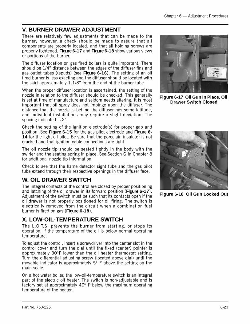
Chapter 6 — Adjustment Procedures
V. BURNER DRAWER ADJUSTMENTThere are relatively few adjustments that can be made to theburner; however, a check should be made to assure that allcomponents are properly located, and that all holding screws areproperly tightened. Figure 6-17 and Figure 6-18 show various viewsor portions of the burner.
The diffuser location on gas fired boilers is quite important. Thereshould be 1/4” distance between the edges of the diffuser fins andgas outlet tubes ((spuds) (see Figure 6-16). The setting of an oilfired burner is less exacting and the diffuser should be located withthe skirt approximately 1-1/8” from the end of the burner tube.
When the proper diffuser location is ascertained, the setting of thenozzle in relation to the diffuser should be checked. This generallyis set at time of manufacture and seldom needs altering. It is mostimportant that oil spray does not impinge upon the diffuser. Thedistance that the nozzle is behind the diffuser has some latitude,and individual installations may require a slight deviation. Thespacing indicated is 2".
Check the setting of the ignition electrode(s) for proper gap andposition. See Figure 6-15 for the gas pilot electrode and Figure 6-14 for the light oil pilot. Be sure that the porcelain insulator is notcracked and that ignition cable connections are tight.
The oil nozzle tip should be seated tightly in the body with theswirler and the seating spring in place. See Section G in Chapter 8for additional nozzle tip information.
Check to see that the flame detector sight tube and the gas pilottube extend through their respective openings in the diffuser face.
W. OIL DRAWER SWITCHThe integral contacts of the control are closed by proper positioningand latching of the oil drawer in its forward position (Figure 6-17).Adjustment of the switch must be such that its contacts open if theoil drawer is not properly positioned for oil firing. The switch iselectrically removed from the circuit when a combination fuelburner is fired on gas (Figure 6-18).
X. LOW-OIL-TEMPERATURE SWITCHThe L.O.T.S. prevents the burner from starting, or stops itsoperation, if the temperature of the oil is below normal operatingtemperature.
To adjust the control, insert a screwdriver into the center slot in thecontrol cover and turn the dial until the fixed (center) pointer isapproximately 30°F lower than the oil heater thermostat setting.Turn the differential adjusting screw (located above dial) until themovable indicator is approximately 5° F above the setting on themain scale.
On a hot water boiler, the low-oil-temperature switch is an integralpart of the electric oil heater. The switch is non-adjustable and isfactory set at approximately 40° F below the maximum operatingtemperature of the heater.
Figure 6-17 Oil Gun In Place, Oil Drawer Switch Closed
Figure 6-18 Oil Gun Locked Out
Part No. 750-225 6-23
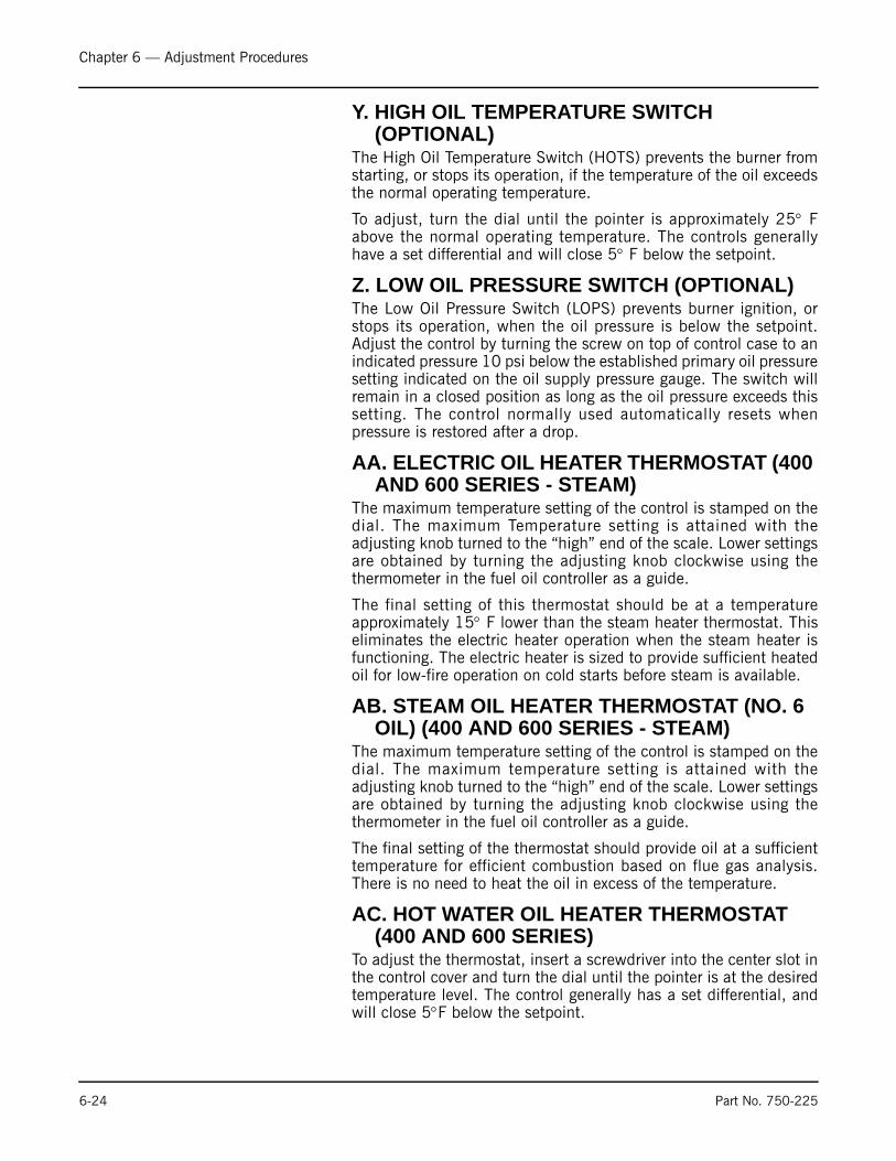
Chapter 6 — Adjustment Procedures
Y. HIGH OIL TEMPERATURE SWITCH (OPTIONAL)
The High Oil Temperature Switch (HOTS) prevents the burner fromstarting, or stops its operation, if the temperature of the oil exceedsthe normal operating temperature.
To adjust, turn the dial until the pointer is approximately 25° Fabove the normal operating temperature. The controls generallyhave a set differential and will close 5° F below the setpoint.
Z. LOW OIL PRESSURE SWITCH (OPTIONAL)The Low Oil Pressure Switch (LOPS) prevents burner ignition, orstops its operation, when the oil pressure is below the setpoint.Adjust the control by turning the screw on top of control case to anindicated pressure 10 psi below the established primary oil pressuresetting indicated on the oil supply pressure gauge. The switch willremain in a closed position as long as the oil pressure exceeds thissetting. The control normally used automatically resets whenpressure is restored after a drop.
AA. ELECTRIC OIL HEATER THERMOSTAT (400 AND 600 SERIES - STEAM)
The maximum temperature setting of the control is stamped on thedial. The maximum Temperature setting is attained with theadjusting knob turned to the “high” end of the scale. Lower settingsare obtained by turning the adjusting knob clockwise using thethermometer in the fuel oil controller as a guide.
The final setting of this thermostat should be at a temperatureapproximately 15° F lower than the steam heater thermostat. Thiseliminates the electric heater operation when the steam heater isfunctioning. The electric heater is sized to provide sufficient heatedoil for low-fire operation on cold starts before steam is available.
AB. STEAM OIL HEATER THERMOSTAT (NO. 6 OIL) (400 AND 600 SERIES - STEAM)
The maximum temperature setting of the control is stamped on thedial. The maximum temperature setting is attained with theadjusting knob turned to the “high” end of the scale. Lower settingsare obtained by turning the adjusting knob clockwise using thethermometer in the fuel oil controller as a guide.
The final setting of the thermostat should provide oil at a sufficienttemperature for efficient combustion based on flue gas analysis.There is no need to heat the oil in excess of the temperature.
AC. HOT WATER OIL HEATER THERMOSTAT (400 AND 600 SERIES)
To adjust the thermostat, insert a screwdriver into the center slot inthe control cover and turn the dial until the pointer is at the desiredtemperature level. The control generally has a set differential, andwill close 5°F below the setpoint.
6-24 Part No. 750-225
Chapter 6 — Adjustment Procedures
The thermostat contacts close to energize the booster water pump,which pumps water from the boiler through the heater. On coldstarts, it is normal practice to manually close the valve in the pumpdischarge line until the boiler water temperature exceeds thetemperature of fuel oil entering the heater.
The electric oil heater on a hot water boiler burning No. 6 oil andequipped with a hot water oil heater has a built-in adjustablethermostat. The maximum temperature setting is stamped on itsdial. The desired temperature can be obtained by turning theadjusting screw. The thermostat should be set at a temperatureapproximately 15 degrees lower than the hot water heaterthermostat. Such a temperature prevents the electric heater fromoperation when the water heater is functioning. The electric heateris sized to provide sufficient heated oil for low-fire operation on coldstarts before hot water is available.
AD. STEAM HEATER PRESSURE REGULATOR (400 AND 600 SERIES - STEAM)
The regulator is provided on a boiler designed to operate atpressures above 15 psi and reduces boiler steam pressure to thelevel necessary for proper operation of the steam oil heater. Thepressure should be reduced to a point that permits sufficienttemperature to heat the oil, while allowing as continuous a steamflow as possible. Pressure that is too high will result in frequentcycling of the steam solenoid valve.
It is best to adjust the regulator under typical flow conditions. To doso, it is suggested that the globe valve in the steam supply line beclosed so that there is no pressure on the regulator. Turn out theadjusting screw fully to relieve compression on the regulator spring,thus closing the regulator. With steam at normal pressure, open theglobe valve and then set the secondary pressure by turning theadjusting screw or handle until the downstream gauge shows thedesired pressure.
Part No. 750-225 6-25
Chapter 6 — Adjustment Procedures
6-26 Part No. 750-94
Notes
Milwaukee, Wisconsin
www.cleaver-brooks.com
Chapter 7Trouble Shooting
Chapter 7 assumes that the unit has been properly installed and adjusted, andthat it has been running for some time. It is further assumed that the operatorhas become thoroughly familiar with both burner and manual by this time. Thepoints under each heading are set down briefly as possible causes, suggestionsor clues to simplify locating the source of trouble. Methods of correcting thetrouble, once it has been identified, may be found elsewhere in this manual.
If the burner will not start or operate properly, the trouble shooting Chaptershould be referred to for assistance in pinpointing problems that may not bereadily apparent.
!WarningTrouble shooting should be performed only by personnel who arefamiliar with the equipment and who have read and understand thecontents of this manual. Failure to follow these instructions could resultin serious personal injury or death
! WarningDisconnect and lock out the main power supply in order to avoid thehazard of electrical shock.Failure to follow these instructions could
result in serious personal injury or death
NoticeIf your boiler is equipped with a CB-HAWK™ boiler management controlsystem, refer to CB-HAWK Installation, Operating and Servicing ManualNo. 750-133 for specific information regarding procedures described inthis section
!

Chapter 7 — Trouble Shooting
7-2 Part No. 750-225
The program relay has the capability to self-diagnose and to display a code ormessage that indicates the failure condition. Refer to the control bulletin forspecifics and suggested remedies.
Familiarity with the programmer and other controls in the system may beobtained by studying the contents of this manual. Knowledge of the system andits controls will make trouble shooting much easier. Costly down-time or delayscan be prevented by systematic checks of actual operation against the normalsequence to determine the stage at which performance deviates from normal.Following a routine may possibly eliminate overlooking an obvious condition,often one that is relatively simple to correct.
If an obvious condition is not apparent, check the continuity of the circuits witha voltmeter or test lamp. Each circuit can be checked and the fault isolated andcorrected. Most circuitry checking can be done between appropriate terminalson the terminal boards in the control cabinet or the entrance box. Refer to theschematic wiring diagram for terminal identification.

Chapter 7 — Trouble Shooting
Part No. 750-225 7-3
PROBLEM SOLUTION
BURNER DOES NOT START
1. No voltage at program relay power input terminals.
A. Main disconnect switch open.
B.Blown control circuit fuse.
C. Loose or broken electrical connection.
2. Program relay safety switch requires resetting.
3. Limit circuit not completed—no voltage at end of limit circuit program relay terminal.
A. Pressure or temperature is above setting of operation control. (Load demand light willnot glow.)
B.Water below required level.
1). Low-water light (and alarm horn)should indicate this condition.
2). Check manual reset button, if provided,on low-water control.
C. Fuel pressure must be within settings of low pressure and high pressure switches.
D.Oil fired unit - burner gun must be in full forward position to close oil drawer switch.
E. ) Heavy oil fired unit - oil temperature below minimum settings.
4. Fuel valve interlock circuit not completed.
A. Fuel valve auxiliary switch not enclosed.
NO IGNITION 1. Lack of spark.
A. Electrode grounded or porcelain cracked.
B. Improper electrode setting.
C. Loose terminal on ignition cable; cable shorted.
D.Inoperative ignition transformer.
E. Insufficient or no voltage at pilot ignition circuit terminal.
2. Spark but no flame.
A. Lack of fuel - no gas pressure, closed valve, empty tank, broken line, etc.
B. Inoperative pilot solenoid.
C. Insufficient or no voltage at pilot ignition circuit terminal.
D.Too much air.
3. Low fire switch open in low fire proving circuit.
A. Damper motor not closed, slipped cam, defective switch.
B.Damper jammed or linkage binding.
4. Running interlock circuit not completed.
A. Combustion or atomizing air proving switches defective or not properly set.
B.Motor starter interlock contact not closed.
5. Flame detector defective, sight tube obstructed, or lens dirty.

Chapter 7 — Trouble Shooting
7-4 Part No. 750-225
PROBLEM SOLUTION
PILOT FLAME, BUT NO MAIN FLAME
1. Insufficient pilot flame.
2. Gas Fired Unit.
A. Manual gas cock closed.
B.Main gas valve inoperative.
C. Gas pressure regulator inoperative.
3. Oil fired unit.
A. Oil supply cut off by obstruction, closed valve, or loss of suction.
B.Supply pump inoperative.
C. No fuel.
D.Main oil valve inoperative.
E. Check oil nozzle, gun and lines.
4. Flame detector defective, sight tube obstructed or lens dirty.
5. Insufficient or no voltage at main fuel valve circuit terminal.
BURNER STAYS IN LOW FIRE
1. Pressure or temperature above modulating control setting.
2. Manual-automatic switch in wrong position.
3. Inoperative modulating motor (see Section F).
4. Defective modulating control.
5. Binding or loose linkage, cams, setscrews, etc.
SHUTDOWN OCCURS DURING FIRING
1. Loss or stoppage of fuel supply.
2. Defective fuel valve; loose electrical connection.
3. Flame detector weak or defective.
4. Lens dirty or sight tube obstructed.
5. If the programmer lockout switch has not tripped, check the limit circuit for anopened safety control.
6. If the programmer lockout switch has tripped:
A. Check fuel lines and valves.
B.Check flame detector.
C. Check for open circuit in running interlock circuit.
D.The flame failure light is energized by ignition failure, main flame failure,inadequate flame signal, or open control in the running interlock circuit.
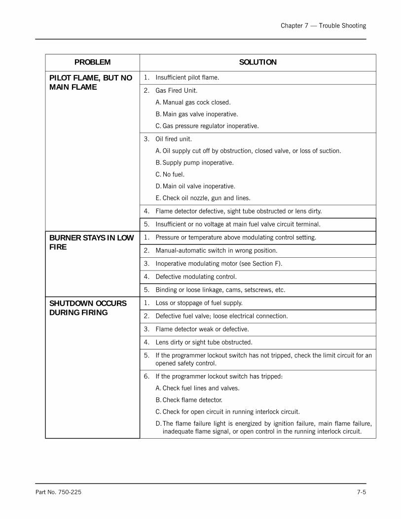
Chapter 7 — Trouble Shooting
Part No. 750-225 7-5
PROBLEM SOLUTION
PILOT FLAME, BUT NO MAIN FLAME
1. Insufficient pilot flame.
2. Gas Fired Unit.
A. Manual gas cock closed.
B.Main gas valve inoperative.
C. Gas pressure regulator inoperative.
3. Oil fired unit.
A. Oil supply cut off by obstruction, closed valve, or loss of suction.
B.Supply pump inoperative.
C. No fuel.
D.Main oil valve inoperative.
E. Check oil nozzle, gun and lines.
4. Flame detector defective, sight tube obstructed or lens dirty.
5. Insufficient or no voltage at main fuel valve circuit terminal.
BURNER STAYS IN LOW FIRE
1. Pressure or temperature above modulating control setting.
2. Manual-automatic switch in wrong position.
3. Inoperative modulating motor (see Section F).
4. Defective modulating control.
5. Binding or loose linkage, cams, setscrews, etc.
SHUTDOWN OCCURS DURING FIRING
1. Loss or stoppage of fuel supply.
2. Defective fuel valve; loose electrical connection.
3. Flame detector weak or defective.
4. Lens dirty or sight tube obstructed.
5. If the programmer lockout switch has not tripped, check the limit circuit for anopened safety control.
6. If the programmer lockout switch has tripped:
A. Check fuel lines and valves.
B.Check flame detector.
C. Check for open circuit in running interlock circuit.
D.The flame failure light is energized by ignition failure, main flame failure,inadequate flame signal, or open control in the running interlock circuit.
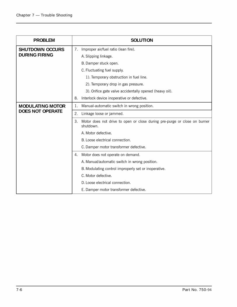
Chapter 7 — Trouble Shooting
7-6 Part No. 750-94
PROBLEM SOLUTION
SHUTDOWN OCCURS DURING FIRING
7. Improper air/fuel ratio (lean fire).
A. Slipping linkage.
B.Damper stuck open.
C. Fluctuating fuel supply.
1). Temporary obstruction in fuel line.
2). Temporary drop in gas pressure.
3). Orifice gate valve accidentally opened (heavy oil).
8. Interlock device inoperative or defective.
MODULATING MOTOR DOES NOT OPERATE
1. Manual-automatic switch in wrong position.
2. Linkage loose or jammed.
3. Motor does not drive to open or close during pre-purge or close on burnershutdown.
A. Motor defective.
B.Loose electrical connection.
C. Damper motor transformer defective.
4. Motor does not operate on demand.
A. Manual/automatic switch in wrong position.
B.Modulating control improperly set or inoperative.
C. Motor defective.
D.Loose electrical connection.
E. Damper motor transformer defective.

Milwaukee, Wisconsin
www.cleaver-brooks.com
Chapter 8
Inspection and Maintenance
ContentsA. GENERAL . . . . . . . . . . . . . . . . . . . . . . . . . . . . . . . . . . . . . . . . . . . . . . . . . . . . . . . . . . . . 8-3B. FIRESIDE CLEANING . . . . . . . . . . . . . . . . . . . . . . . . . . . . . . . . . . . . . . . . . . . . . . . . . . . . 8-4C. WATER LEVEL CONTROLS . . . . . . . . . . . . . . . . . . . . . . . . . . . . . . . . . . . . . . . . . . . . . . . . 8-4D. WATER GAUGE GLASS . . . . . . . . . . . . . . . . . . . . . . . . . . . . . . . . . . . . . . . . . . . . . . . . . . . 8-5E. ELECTRICAL CONTROLS . . . . . . . . . . . . . . . . . . . . . . . . . . . . . . . . . . . . . . . . . . . . . . . . . 8-6F. FLAME SAFETY CONTROL . . . . . . . . . . . . . . . . . . . . . . . . . . . . . . . . . . . . . . . . . . . . . . . . . 8-6G. OIL BURNER MAINTENANCE . . . . . . . . . . . . . . . . . . . . . . . . . . . . . . . . . . . . . . . . . . . . . . 8-9H. GAS BURNER MAINTENANCE . . . . . . . . . . . . . . . . . . . . . . . . . . . . . . . . . . . . . . . . . . . . 8-11I. MOTORIZED GAS VALVE . . . . . . . . . . . . . . . . . . . . . . . . . . . . . . . . . . . . . . . . . . . . . . . . . 8-11J. SOLENOID VALVES . . . . . . . . . . . . . . . . . . . . . . . . . . . . . . . . . . . . . . . . . . . . . . . . . . . . . 8-12K. AIR CONTROL DAMPER, LINKAGE AND CAM SPRING . . . . . . . . . . . . . . . . . . . . . . . . . . . 8-12L. FORCED DRAFT FAN . . . . . . . . . . . . . . . . . . . . . . . . . . . . . . . . . . . . . . . . . . . . . . . . . . . 8-13M. FAN/MOTOR CASSETTE REMOVAL . . . . . . . . . . . . . . . . . . . . . . . . . . . . . . . . . . . . . . . . . 8-13N. INSPECTION AND ADJUSTMENT . . . . . . . . . . . . . . . . . . . . . . . . . . . . . . . . . . . . . . . . . . 8-14O. AIRBOX GASKET INSTALLATION . . . . . . . . . . . . . . . . . . . . . . . . . . . . . . . . . . . . . . . . . . . 8-17P. FAN/MOTOR CASSETTE INSTALLATION . . . . . . . . . . . . . . . . . . . . . . . . . . . . . . . . . . . . . . 8-18Q. SAFETY VALVES . . . . . . . . . . . . . . . . . . . . . . . . . . . . . . . . . . . . . . . . . . . . . . . . . . . . . . 8-19R. FUEL OIL METERING VALVE, ADJUSTING AND RELIEF VALVES . . . . . . . . . . . . . . . . . . . . 8-19S. THE AIR PUMP AND LUBRICATING SYSTEM . . . . . . . . . . . . . . . . . . . . . . . . . . . . . . . . . . 8-24T. REFRACTORY . . . . . . . . . . . . . . . . . . . . . . . . . . . . . . . . . . . . . . . . . . . . . . . . . . . . . . . . 8-28U. OPENING AND CLOSING REAR DOOR . . . . . . . . . . . . . . . . . . . . . . . . . . . . . . . . . . . . . . 8-33V. LUBRICATION . . . . . . . . . . . . . . . . . . . . . . . . . . . . . . . . . . . . . . . . . . . . . . . . . . . . . . . . 8-35W. OIL HEATERS - ELECTRIC, STEAM, HOT WATER . . . . . . . . . . . . . . . . . . . . . . . . . . . . . . . 8-37X. COMBUSTION . . . . . . . . . . . . . . . . . . . . . . . . . . . . . . . . . . . . . . . . . . . . . . . . . . . . . . . . 8-38
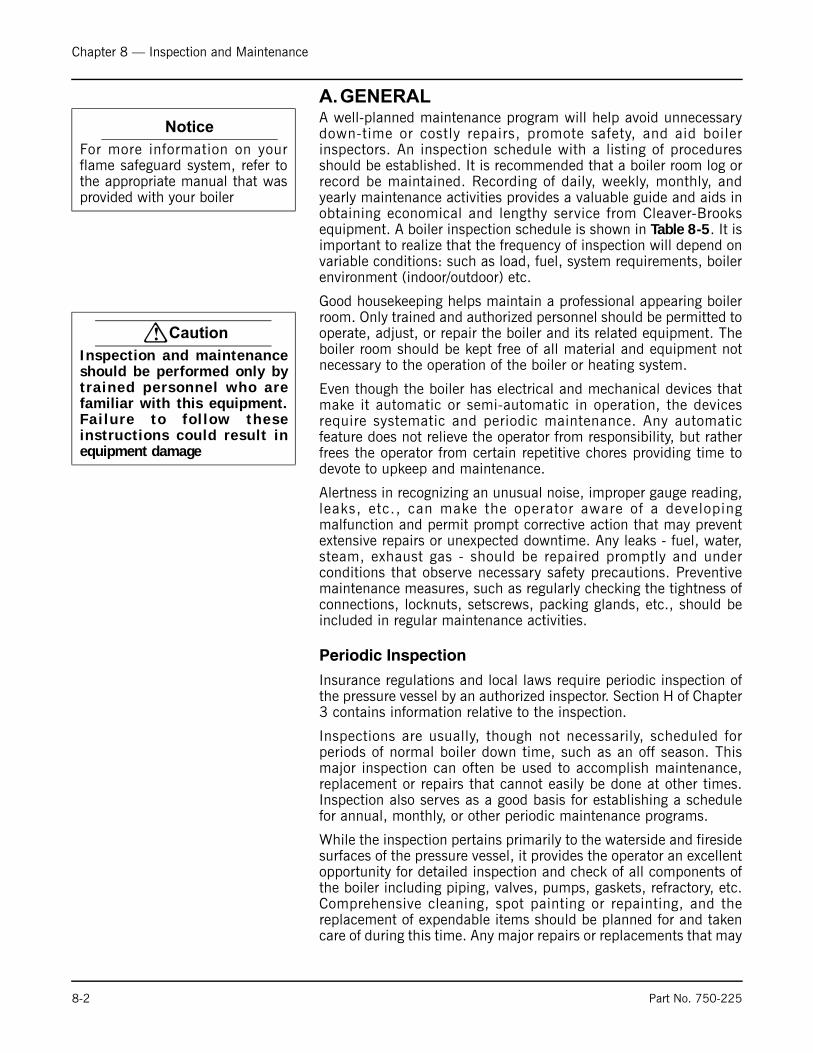
Chapter 8 — Inspection and Maintenance
A.GENERALA well-planned maintenance program will help avoid unnecessarydown-time or costly repairs, promote safety, and aid boilerinspectors. An inspection schedule with a listing of proceduresshould be established. It is recommended that a boiler room log orrecord be maintained. Recording of daily, weekly, monthly, andyearly maintenance activities provides a valuable guide and aids inobtaining economical and lengthy service from Cleaver-Brooksequipment. A boiler inspection schedule is shown in Table 8-5. It isimportant to realize that the frequency of inspection will depend onvariable conditions: such as load, fuel, system requirements, boilerenvironment (indoor/outdoor) etc.
Good housekeeping helps maintain a professional appearing boilerroom. Only trained and authorized personnel should be permitted tooperate, adjust, or repair the boiler and its related equipment. Theboiler room should be kept free of all material and equipment notnecessary to the operation of the boiler or heating system.
Even though the boiler has electrical and mechanical devices thatmake it automatic or semi-automatic in operation, the devicesrequire systematic and periodic maintenance. Any automaticfeature does not relieve the operator from responsibility, but ratherfrees the operator from certain repetitive chores providing time todevote to upkeep and maintenance.
Alertness in recognizing an unusual noise, improper gauge reading,leaks, etc., can make the operator aware of a developingmalfunction and permit prompt corrective action that may preventextensive repairs or unexpected downtime. Any leaks - fuel, water,steam, exhaust gas - should be repaired promptly and underconditions that observe necessary safety precautions. Preventivemaintenance measures, such as regularly checking the tightness ofconnections, locknuts, setscrews, packing glands, etc., should beincluded in regular maintenance activities.
Periodic Inspection
Insurance regulations and local laws require periodic inspection ofthe pressure vessel by an authorized inspector. Section H of Chapter3 contains information relative to the inspection.
Inspections are usually, though not necessarily, scheduled forperiods of normal boiler down time, such as an off season. Thismajor inspection can often be used to accomplish maintenance,replacement or repairs that cannot easily be done at other times.Inspection also serves as a good basis for establishing a schedulefor annual, monthly, or other periodic maintenance programs.
While the inspection pertains primarily to the waterside and firesidesurfaces of the pressure vessel, it provides the operator an excellentopportunity for detailed inspection and check of all components ofthe boiler including piping, valves, pumps, gaskets, refractory, etc.Comprehensive cleaning, spot painting or repainting, and thereplacement of expendable items should be planned for and takencare of during this time. Any major repairs or replacements that may
Notice
For more information on yourflame safeguard system, refer tothe appropriate manual that wasprovided with your boiler
! Caution
Inspection and maintenanceshould be performed only byt ra ined personnel who arefamiliar with this equipment.Fa i lu re to f o l l ow theseinstructions could result inequipment damage
8-2 Part No. 750-225

Chapter 8 — Inspection and Maintenance
be required should also, if possible, be coordinated with the periodof boiler shutdown.
Replacement spare parts, if not on hand, should be orderedsufficiently prior to shutdown.
Cleaver-Brooks boilers are designed, engineered, and built to provide long life and excellent service. Good operating practices and conscientious maintenance and care will assure efficiency and economy from their operation, and will contribute to many years of performance.
A total protection plan includes a Planned Maintenance Program that covers many of the items included in this chapter.
For information regarding a total protection plan, contact your local Cleaver-Brooks authorized representative.
B. FIRESIDE CLEANINGSoot and non-combustibles are effective insulators, and, if allowedto accumulate, will reduce heat transfer to the water and increasefuel consumption. Soot and other deposits can be very moisture-absorbent, and may attract moisture to form corrosive acids thatwill deteriorate fireside metal.
Clean-out should be performed at regular and frequent intervals,depending upon load, type, and quality of fuel, internal boilertemperature, and combustion efficiency. A stack temperaturethermometer can be used as a guide to clean-out intervals since anaccumulation of soot deposits will raise the flue gas temperature.
Tube cleaning is accomplished by opening the front and rear doors.Tubes may be brushed from either end. All loose soot andaccumulations should be removed. Any soot, or other deposits,should be removed from the furnace and tube sheets.
Refer to Section U of Chapter 8 for instructions on properly closingrear heads.
The flue gas outlet and stack should be inspected annually andcleaned as necessary. Commercial firms are available to perform thework. The stack should be inspected for damage and repaired asrequired.
The fireside should be thoroughly cleaned prior to any extended lay-up of the boiler. Depending upon circumstances, a protectivecoating may be required. See Section I in Chapter 3.
C. WATER LEVEL CONTROLS The need to periodically check water level controls and thewaterside of the pressure vessel cannot be overemphasized. Mostinstances of major boiler damage are the result of operating withlow water, or the use of untreated (or incorrectly) treated water.
Always be sure of the boiler water level. On steam boilers, the watercolumn should be blown down daily. Check samples of boiler waterand condensate in accordance with procedures recommended by
Notice
Cleaver-Brooks genuine partsshould be used to ensure properoperation.Contact your localCleaver-Brooks representative forparts information and ordering
Part No. 750-225 8-3
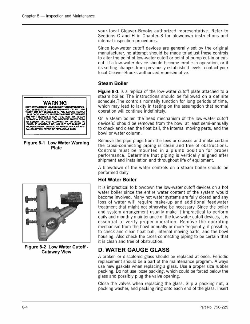
Chapter 8 — Inspection and Maintenance
your local Cleaver-Brooks authorized representative. Refer toSections G and H in Chapter 3 for blowdown instructions andinternal inspection procedures.
Since low-water cutoff devices are generally set by the originalmanufacturer, no attempt should be made to adjust these controlsto alter the point of low-water cutoff or point of pump cut-in or cut-out. If a low-water device should become erratic in operation, or ifits setting changes from previously established levels, contact yourlocal Cleaver-Brooks authorized representative.
Steam Boiler
Figure 8-1 is a replica of the low-water cutoff plate attached to asteam boiler. The instructions should be followed on a definiteschedule.The controls normally function for long periods of time,which may lead to laxity in testing on the assumption that normaloperation will continue indefinitely.
On a steam boiler, the head mechanism of the low-water cutoffdevice(s) should be removed from the bowl at least semi-annuallyto check and clean the float ball, the internal moving parts, and thebowl or water column.
Remove the pipe plugs from the tees or crosses and make certainthe cross-connecting piping is clean and free of obstructions.Controls must be mounted in a plumb position for properperformance. Determine that piping is vertically aligned aftershipment and installation and throughout life of equipment.
A blowdown of the water controls on a steam boiler should beperformed daily
Hot Water Boiler
It is impractical to blowdown the low-water cutoff devices on a hotwater boiler since the entire water content of the system wouldbecome involved. Many hot water systems are fully closed and anyloss of water will require make-up and additional feedwatertreatment that might not otherwise be necessary. Since the boilerand system arrangement usually make it impractical to performdaily and monthly maintenance of the low-water cutoff devices, it isessential to verify proper operation. Remove the operatingmechanism from the bowl annually or more frequently, if possible,to check and clean float ball, internal moving parts, and the bowlhousing. Also check the cross-connecting piping to be certain thatit is clean and free of obstruction.
D. WATER GAUGE GLASSA broken or discolored glass should be replaced at once. Periodicreplacement should be a part of the maintenance program. Alwaysuse new gaskets when replacing a glass. Use a proper size rubberpacking. Do not use loose packing, which could be forced below theglass and possibly plug the valve opening.
Close the valves when replacing the glass. Slip a packing nut, apacking washer, and packing ring onto each end of the glass. Insert
Figure 8-1 Low Water Warning Plate
Figure 8-2 Low Water Cutoff - Cutaway View
8-4 Part No. 750-225
Chapter 8 — Inspection and Maintenance
one end of the glass into the upper gauge valve body far enough toallow the lower end to be dropped into the lower body. Slide thepacking nuts onto each valve and tighten.
It is recommended that the boiler is off and cool when the glass isreplaced. However if the glass is replaced while the boiler is inservice, open the blowdown and slowly bring the glass to operatingtemperature by opening the gauge valves slightly. After glass iswarmed up, close the blowdown valve and open the gauge valvescompletely.
Check try-cocks and gauge cocks for freedom of operation and cleanas required. It is imperative that the gauge cocks are mounted inexact alignment. If they are not, the glass will be strained and mayfail prematurely.
E. ELECTRICAL CONTROLSThe operating controls should be inspected monthly. Examinetightness of electrical connections and keep the controls clean.Remove any dust that accumulates in the interior of the controlusing a low pressure air. Take care not to damage the mechanism.
Examine any mercury tube switches for damage or cracks. Darkscum over the normally bright surface of the mercury, may lead toerratic switching action. Be certain that controls are correctlyleveled. The piping leading to the pressure control actuators shouldbe cleaned, if necessary. Covers should be left on controls at alltimes.
Dust and dirt can cause excessive wear and overheating of motorstarter and relay contacts. Use a burnishing tool or a hard surfacepaper to clean and polish contacts. Starter contacts are plated withsilver and are not harmed by discoloration and slight pitting.Replacement of the contacts is necessary only if the silver has wornthin.
Thermal relay units (overloads) are of the melting-alloy type and,when tripped, the alloy must be given time to re-solidify before relaycan be reset. If the overloads trip out repeatedly when the motorcurrent is normal, replace them with new overloads. If the conditioncontinues after replacement, it will be necessary to determine thecause of excessive current draw at the overloads.
Power supply to the boiler must be protected with dual elementfuses (fusetrons) or circuit breakers. Similar fuses should be used inbranch circuits. Standard one-shot fuses are not recommended.Information given in Figure 8-1 is included for guidance to fuserequirements.
F. FLAME SAFETY CONTROLThe microprocessor based control requires minimal maintenancebecause the safety and logic timings are inaccessible. There also arenot any accessible contacts. Check to see that the retaining screwis securely holding the chassis to the mounting base. Also check tosee that the amplifier and the program module are tightly inserted.
! Warning
Do not attempt to change thegauge glass while the boiler isin service. Failure to followthese instructions could resultin serious personal injury ordeath
! Caution
Do not use files or abrasivematerials such as sandpaper onthe contact points. Failure tofollow these instructions couldresult in equipment damage.
Part No. 750-225 8-5

Chapter 8 — Inspection and Maintenance
Table 8-1 Recommended Maximum “Fusetron” Fuse Sizes
The relay's self-diagnostic ability includes advising when it or itsplug-in modules are at fault and require replacement.
Your spare control should be stored in a dry atmosphere andwrapped in plastic. During an extended shutdown (e.g., seasonal),the active control should be removed and stored. Moisture cancause problems with control operation.
It is recommended that service be rotated between the active and aspare control to assure a working replacement is available.
Be sure the connecting contacts on the control and its base are notbent out of position.
The flame detector lens should be cleaned as often as operatingconditions demand. Use a soft cloth moistened with detergent toclean the lens.
SECONDARY FUSE
550-600
440-480
346-416
220-240
200-208
110-120
15 KW HEATER
10 KW HEATER
7-1/2 KW HEATER
5 KW HEATER
3 KW HEATER
2 KW HEATER
200 HP MOTOR
150 HP MOTOR
125 HP MOTOR
100 HP MOTOR
75 HP MOTOR
60 HP MOTOR
50 HP MOTOR
40 HP MOTOR
30 HP MOTOR
25 HP MOTOR
20 HP MOTOR
15 HP MOTOR
10 HP MOTOR
7-1/2 HP MOTOR
5 HP MOTOR
3 HP MOTOR
2 HP MOTOR
1-1/2 HP MOTOR
1 HP MOTOR
3/4 HP MOTOR
1/2 HP MOTOR
1/3 HP MOTOR
1/4 HP MOTOR
FRN-5-6/10
FRS-2
FRS-2-1/2
FRS-2-8/10
FRN-3-1/2
FRN-4
FRN-7
FRN-50
FRN-30
FRN-20
FRN-40
FRN-30
FRN-25
FRN-20
FRN-17-1/2
FRN-12
FRN-9
FRN-8
FRN-12
FRS-3-1/2
FRS-3-1/2
FRS-4
FRN-7
FRN-8
FRN-15
FRN-25
FRN-15
FRN-12
FRN-60
FRN-50
FRN-35
FRN-20
FRN-15
FRN-12
FRN-10
FRN-9
FRN-6-1/4
FRN-4-1/2
FRN-4-1/2
FRN-15
FRS-4-1/2
FRS-5-6/10
FRS-6-1/4
FRN-10
FRN-12
FRN-17-1/2
FRN-45
FRN-30
FRN-25
FRN-15
FRN-10
FRN-7
FRN-450
FRN-350
FRN-250
FRN-200
FRN-175
FRN-150
FRN-100
FRN-90
FRN-70
FRN-60
FRN-40
FRN-30
FRN-20
FRN-12
FRN-9
FRN-7
FRN-5
FRN-4-1/2
FRN-2-8/10
FRN-1-8/10
FRN-1-8/10
FRN-20
FRS-5-6/10
FRS-7
FRS-8
FRN-12
FRN-15
FRN-25
FRN-45
FRN-30
FRN-25
FRN-15
FRN-10
FRN-7
FRN-600
FRN-4-1/2
FRN-2-8/10
FRN-1-8/10
FRN-1-8/10
FRS-35
FRS-25
FRS-15
FRS-10
FRS-6-1/4
FRS-150
FRS-125
FRS-100
FRS-80
FRS-60
FRS-50
FRS-40
FRS-30
FRS-20
FRS-17-1/2
FRS-12
FRS-8
FRS-5-6/10
FRS-4
FRS-3-2/10
FRS-2-1/4
FRS-1-8/10
FRS-25
FRS-17-1/2
FRS-12
FRS-8
FRS-5-6/10
FRS-4-1/2
FRS-300
FRS-225
FRS-200
FRS-150
FRS-125
FRS-100
FRS-80
FRS-70
FRS-50
FRS-40
FRS-35
FRS-25
FRS-17-1/2
FRS-15
FRS-10
FRS-6-1/4
FRS-4-1/2
FRS-3-2/10
FRS-2-1/4
FRS-1-8/10
FRS-1-4/10
FRS-1
FRS-1
FRS-20
FRS-12
FRS-10
FRS-6-1/4
FRS-4-1/2
FRS-3-2/10
FRS-250
FRS-200
FRS-150
FRS-125
FRS-100
FRS-80
FRS-70
FRS-50
FRS-40
FRS-35
FRS-25
FRS-20
FRS-15
FRS-12
FRS-8
FRS-5
FRS-3-1/2
FRS-2-1/2
FRS-1-8/10
FRS-1-4/10
FRS-1
FRS-8/10
FRS-8/10
ELECTRICAL LOAD110-120 V
SINGLE PHASE 50/60 HERTZ
220-240 V 200-208 V 220-240 V
THREE PHASE 50/60 HERTZ
346-416 V 440-480 V 550-660 V
RECOMMENDED MAXIMUM "FUSETRON" FUSE SIZES
FRN-500 FRN-450
FRN-5
FRN-7
FRN-9
FRN-12
FRN-20
FRN-30
FRN-35
FRN-50
FRN-70
FRN-80
FRN-100
FRN-150
FRN-175
FRN-200
FRN-250
FRN-300
FRN-400
1/2 KVA. 1 KVA. 1-1/2 KVA. 2 KVA.CONTROL CIRCUIT
XFMR VOLTAGE
CONSULT CLEAVER-BROOKS ELECTRICAL ENGINEERING DEPT. FOR "FUSETRON" FUSE SIZE
FOR POWER SYSTEMS WITH VOLTAGE, FREQUENCY OR PHASE NOT MENTIONED ABOVE.
MOTOR, OIL HEATER, & CCT FUSE SIZING
! Warning
When replacing a control, besure to lock out the mainpower supply switch since thecontrol is “hot” even thoughthe burner switch is of f.Fa i lu re to fo l l ow theseinstructions could result inserious personal injury ordeath.
8-6 Part No. 750-225
Chapter 8 — Inspection and Maintenance
A safety check procedure should be established to test the completesafeguard system at least once a month, or more often. Tests shouldverify safety shutdown and a safety lockout upon failure to ignite thepilot, upon failure to ignite the main flame, and upon loss of flame.Each of the conditions should be checked on a scheduled basis.
The following tests should be used to test the complete safeguardsystem. If the sequence of events is not as described, then aproblem may exist. Contact your local Cleaver-Brooks authorizedrepresentative for assistance.
Checking Pilot Flame Failure
Close the gas pilot shutoff cock Chapter 2, Figure 2-11). Also shutoff the main fuel supply. Turn the burner switch “on.”
The pilot ignition circuit will be energized at the end of the pre-purgeperiod. There should be an ignition spark, but no flame. Since thereis no flame to be detected, the program relay will signal thecondition. The ignition circuit will deenergize and the control willlock out on a safety shutdown. The flame failure light (and optionalalarm) will be activated. The blower motor will run through the post-purge and stop.
Turn the burner switch off. Reset the safety switch. Reopen the gaspilot shutoff cock and re-establish main fuel supply.
Checking Failure to Light Main Flame
Leave the gas pilot shutoff cock open. Shut off the main burner fuelsupply. Turn the burner switch on. The pilot will light uponcompletion of the pre-purge period. The main fuel valve(s) will beenergized, but there should be no main flame.
The fuel valve(s) deenergize within 4 seconds after the main burnerignition trial ends. The control will lock out on a safety shutdown.The flame failure light (and optional alarm) will be activated. Theblower motor will run through the post-purge and stop.
Turn the burner switch off. Reset the safety switch. Re-establishmain fuel supply.
Checking Loss of Flame
With the burner in normal operation, shut off the main burner fuelsupply to extinguish main flame.
The fuel valve(s) will be deenergized and the relay will signal thecondition within 4 seconds. The control will then lock out on asafety shutdown. The flame failure light (and optional alarm) will beactivated. The blower motor will run through the post-purge andstop.
Turn the burner switch off. Reset the safety switch. Re-establishmain fuel supply.
Part No. 750-225 8-7

Chapter 8 — Inspection and Maintenance
The flame detector lens should be cleaned as often as operatingconditions demand. Use a soft cloth moistened with detergent ifnecessary.
G. OIL BURNER MAINTENANCEThe burner should be inspected for evidence of damage due toimproperly adjusted combustion. Any soot buildup on the diffuser orthe oil nozzle should be removed. The setting of the oil nozzle inrelation to the diffuser and other components is important for properfiring and should be checked. See Section T in Chapter 6.
Oil Strainers
Oil strainers should be cleaned frequently to maintain a free and fullflow of fuel.
Light Oil Strainers
The fuel oil strainer screen must be removed and cleaned at regularintervals. It is advisable to remove the screen each month and cleanthoroughly by immersing it in solvent and blowing it dry withcompressed air. To remove, loosen the cover cap screw, beingcareful not to lose the copper gasket. If necessary, tap the strainercover gently to loosen. Check the cover gasket for damage andreplace if necessary. Slip pliers into the cross on the top of thestrainer and twist counter-clockwise to remove the basket.Reassemble in reverse order.
Heavy Oil Strainers
Keep the cartridge of the oil strainer clear by regularly giving theexterior handle one complete turn in either direction. Do so thisoften until experience indicates cleaning frequency necessary tomaintain optimum conditions of flow. If the handle turns hard,rotate the handle back and forward until it can be turned through acomplete revolution. Do not force it with a wrench or other tool.
Drain the sump as often as experience indicates the necessity.Remove the sump, or the head and cartridge assembly, for thoroughcleaning and inspection at frequent intervals. Exercise care not todamage the cartridge discs or the cleaner blades. Wash thecartridge in solvents. Do not attempt to disassemble the cartridge.
Cleaning Oil Nozzle
The design of the burner, together with the oil purge system on aheavy oil burner, make it unnecessary to clean the oil nozzle duringperiods of operation. A routine check and any necessary cleaningshould be made during off periods or when the burner is firing ongas.
If at any time the burner flame appears “stringy” or “lazy,” it ispossible that the nozzle tip or swirler has become partially cloggedor worn. Any blockage within the tip will cause the air pressuregauge to increase above its normal value.
8-8 Part No. 750-225

Chapter 8 — Inspection and Maintenance
Disassemble with the power off by unlatching and withdrawing theburner gun. Insert the nozzle body into the hanger vice and use thespanner wrench to remove the tip. Carefully remove the swirler andseating spring being careful not to drop or damage any parts. SeeFigure 8-3 and Figure 8-4.
Perform any necessary cleaning with a suitable solvent. Use a softfiber brush or pointed piece of soft wood for cleaning. Do not usewire or a sharp metallic object, which could scratch or deform theorifices as well as the precision ground surfaces of the swirler andtip. Inspect for scratches or signs of wear or erosion, which maymake the nozzle unfit for further use. Take the necessaryprecautions in working with solvents.
The tip and swirler are a matched set, which are precision lappedat the time of assembly. The close fit of the lapped surfaces mustbe maintained in order to provide optimum performance. Additionallapping may be required to provide better atomization for moreefficient combustion. Do not interchange parts if a spare is kept. Inreassembling, be certain that the seating spring is in place and thatit is holding the swirler tightly against the tip. The swirler isstationary and does not rotate, but rather imparts a swirling motionto the oil.
See that the plugged hole is at the bottom of the nozzle body whenthe gun is installed.
Cleaning Air Purge Nozzle (No. 6 Oil) and Back Pressure Orifice Nozzle (No. 2 Oil)
The air purge nozzle and its strainer should be inspectedperiodically and cleaned. The nozzle consists of a tip and internalcore. Clean all internal surfaces of the tip and the slotted parts ofthe core using a wood splinter to avoid damage from scratching.Replace the core, setting it tightly but not excessively so.
Clean the strainer screen carefully to remove any foreign matter.Use suitable solvents in cleaning. Extremely hot water at highvelocity is also helpful in cleaning. Replace strainer by screwing itinto the nozzle body only finger tight. Do not use an orifice of a sizeother than originally installed.
Ignition System
For best results, maintain the proper gap and dimensions of theignition electrode(s). Figures 6-14 and 6-15 (Chapter 6) show theproper settings.
Inspect the electrode tip for signs of pitting or combustion depositsand dress as required with a fine file. Inspect the porcelain insulator(s) for any cracks that might be present. If there are cracks, replacethe electrode since they can cause grounding of the ignition voltage.Since carbon is an electrical conductor, it is necessary to keep theinsulating portion of electrode(s) wiped clean if any carbon ispresent. Ammonia will aid in removing carbon or soot.
Figure 8-3 Standard Burner Nozzle Components
NOZZLE BODY
SPRING
STANDARD NOZZLE
SPANNER WRENCH
TIP
SWIRLER
Figure 8-4 High Turndown Burner Nozzle Components
NOZZLE BODY
SPRING
SWIRLER
SPANNER WRENCH
HIGH TURNDOWN
NOZZLE TIIP
Part No. 750-225 8-9
Chapter 8 — Inspection and Maintenance
Check ignition cables for cracks in the insulation. Also see that allconnections between the transformer and the electrodes are tight.
Periodically remove the access plug from the gas pilot aspirator(Chapter 6, Figure 6-15) and clean out any accumulated lint orother foreign material.
H. GAS BURNER MAINTENANCEThe gas burner components should be inspected for evidence ofdamage due to improperly adjusted combustion. Combustionadjustments should be checked monthly. See Section T in Chapter6.
Check periodically for a proper seal between the end of the burnerhousing and boiler refractory. Any deterioration of the seal shouldbe corrected, as an improper or poor seal allows air leaks, whichcan cause overheating or burning of the burner housing.
Whenever the burner is removed, the diffuser, gas housing and gasspuds (HTB model only) should be checked for any deterioration.Verify that the diffuser skirt conforms to the bore of the burnerhousing so as to minimize the amount of combustion air whichbypasses the diffuser. If the burner is a high turndown burner (HTB)model, check to see that the diffuser is properly located in referenceto the gas spuds. There should be 1/4” between the edge of thediffuser fins and the gas spuds when the burner is installed. Checkto see that the diffuser fins do not interfere with the gas ports or gasspuds in the burner housing (see Chapter 6, Figure 6-14). SeeSection V in Chapter 6 for more information.
Check the electrode setting for any cracks that might be present onthe porcelain insulator. Replace the electrode if cracking is evident,since cracking can cause grounding of the ignition voltage. Inspectthe tip of the electrode for signs of pitting, combustion deposits andwear, and dress as required with a fine file. See Chapter 6, Figure6-14 & 6-15 for electrode settings.
Periodically remove the access plug from the gas pilot aspirator (seeChapter 6, Figure 6-16) and clean out any accumulated lint or otherforeign material.
Check the ignition cables for cracks in the insulation. Verify that allconnections between the transformer and the electrode are tight.
I. MOTORIZED GAS VALVEThe motorized gas valve (Hydramotor) operating mechanism iscompletely immersed in oil and little maintenance is requiredbecause of the sealed design. However, proper operation should bechecked on a routine periodic basis.
Keep outer parts of the valve clean, especially the stem between theoperator and the valve. A nicked, scored or otherwise damagedvalve stem can cause leakage. Do not remove dust covers ifinstalled.
8-10 Part No. 750-225

Chapter 8 — Inspection and Maintenance
The packing gland is of the O-ring type. If oil is noticed around theoperator base or if leakage occurs, repair by replacing any leakingO-rings and refilling the actuator with oil.
If the actuator is sluggish or fails to operate, even after the oil levelis checked, replace the entire operator portion.
J. SOLENOID VALVESForeign matter between the valve seat and seat disc can causeleakage. Valves are readily disassembled; however, care must beused during disassembly to be sure that internal parts are notdamaged during the removal and that reassembly is in proper order.
A low hum or buzzing will normally be audible when the coil isenergized. If the valve develops a loud buzzing or chattering noise,check for proper voltage and clean the plunger assembly andinterior plunger tube thoroughly. Do not use any oil. Be sure that theplunger tube and solenoid are tight when reassembled. Take carenot to nick, dent, or damage the plunger tube.
Coils may be replaced without removing the valve from the line.
Check coil position and make sure that any insulating washers orretaining springs are reinstalled in proper order.
K. AIR CONTROL DAMPER, LINKAGE AND CAM SPRING
The burner air control damper should be checked for free movementas a part of the monthly inspection. With the burner off and thejackshaft damper control rod disconnected, the air control dampershould rotate freely through its entire range of movement. Anyresistance to movement or excessive play in the support bearingshould be investigated and corrected before the burner is put backin operation.
The overall tightness of the linkage assembly should be checkedmonthly. If necessary, tighten the setscrews and the connections atthe uniballs. Check the uniballs for wear and replace if necessary.
The linkage assembly should be tight but should not bind. If thelinkage assembly is binding, determine the cause of the binding andcorrect as necessary.
Linkage rod end attachment points should be marked on thevariable displacement linkage arms as an aid in subsequentreassembly.
Inspection of the air damper and linkage bearings should beperformed on a more frequent basis if the boiler is operating in adirty environment.
The fuel cam profile spring should be inspected monthly for wear,scoring or distortion. If any of the questionable conditions are found,the spring must be replaced immediately to avoid the possibility ofbreakage in service. Use care to avoid damaging the cam or springduring installation.
Lubricate occasionally with a non-gumming, dripless, high-temperature lubricant such as graphite or a silicone derivative.
! Warning
Be sure to turn off power tothe valve in order to avoidelectrical shock. Failure tofollow these instructions couldresult in serious personalinjury or death.
! Caution
Combustion should be checkedand readjusted as requiredwhenever the burner is removedor any cont ro l l i nkage i sdisturbed. Failure to follow theseinstructions could result inequipment damage.
Part No. 750-225 8-11
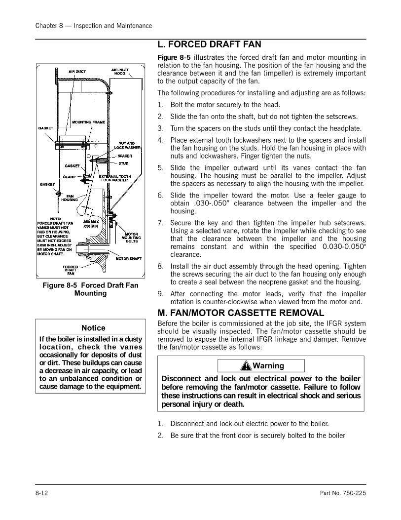
Chapter 8 — Inspection and Maintenance
L. FORCED DRAFT FAN
Figure 8-5 illustrates the forced draft fan and motor mounting inrelation to the fan housing. The position of the fan housing and theclearance between it and the fan (impeller) is extremely importantto the output capacity of the fan.
The following procedures for installing and adjusting are as follows:
1. Bolt the motor securely to the head.
2. Slide the fan onto the shaft, but do not tighten the setscrews.
3. Turn the spacers on the studs until they contact the headplate.
4. Place external tooth lockwashers next to the spacers and installthe fan housing on the studs. Hold the fan housing in place withnuts and lockwashers. Finger tighten the nuts.
5. Slide the impeller outward until its vanes contact the fanhousing. The housing must be parallel to the impeller. Adjustthe spacers as necessary to align the housing with the impeller.
6. Slide the impeller toward the motor. Use a feeler gauge toobtain .030-.050” clearance between the impeller and thehousing.
7. Secure the key and then tighten the impeller hub setscrews.Using a selected vane, rotate the impeller while checking to seethat the clearance between the impeller and the housingremains constant and within the specified 0.030-0.050"clearance.
8. Install the air duct assembly through the head opening. Tightenthe screws securing the air duct to the fan housing only enoughto create a seal between the neoprene gasket and the housing.
9. After connecting the motor leads, verify that the impellerrotation is counter-clockwise when viewed from the motor end.
M. FAN/MOTOR CASSETTE REMOVAL Before the boiler is commissioned at the job site, the IFGR systemshould be visually inspected. The fan/motor cassette should beremoved to expose the internal IFGR linkage and damper. Removethe fan/motor cassette as follows:
1. Disconnect and lock out electric power to the boiler.
2. Be sure that the front door is securely bolted to the boiler
Figure 8-5 Forced Draft Fan Mounting
Notice
If the boiler is installed in a dustyloca t i on , check the vanesoccasionally for deposits of dustor dirt. These buildups can causea decrease in air capacity, or leadto an unbalanced condition orcause damage to the equipment.
! Warning
Disconnect and lock out electrical power to the boilerbefore removing the fan/motor cassette. Failure to followthese instructions can result in electrical shock and seriouspersonal injury or death.
8-12 Part No. 750-225
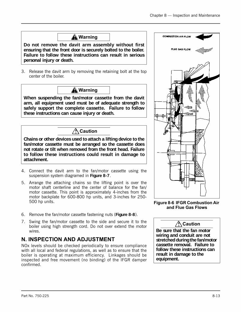
Chapter 8 — Inspection and Maintenance
3. Release the davit arm by removing the retaining bolt at the topcenter of the boiler.
4. Connect the davit arm to the fan/motor cassette using thesuspension system diagramed in Figure 8-7.
5. Arrange the attaching chains so the lifting point is over themotor shaft centerline and the center of balance for the fan/motor cassette. This point is approximately 4-inches from themotor backplate for 600-800 hp units, and 3-inches for 250-500 hp units.
6. Remove the fan/motor cassette fastening nuts (Figure 8-8).
7. Swing the fan/motor cassette to the side and secure it to theboiler using high strength cord. Do not over extend the motorwires.
N. INSPECTION AND ADJUSTMENTNOx levels should be checked periodically to ensure compliancewith all local and federal regulations, as well as to ensure that theboiler is operating at maximum efficiency. Linkages should beinspected and free movement (no binding) of the IFGR damperconfirmed.
Figure 8-6 IFGR Combustion Air and Flue Gas Flows
! Warning
Do not remove the davit arm assembly without firstensuring that the front door is securely bolted to the boiler.Failure to follow these instructions can result in seriouspersonal injury or death.
! Warning
When suspending the fan/motor cassette from the davitarm, all equipment used must be of adequate strength tosafely support the complete cassette. Failure to followthese instructions can cause injury or death.
! Caution
Chains or other devices used to attach a lifting device to thefan/motor cassette must be arranged so the cassette doesnot rotate or tilt when removed from the front head. Failureto follow these instructions could result in damage toattachment.
! Caution
Be sure that the fan motor wiring and conduit are not stretched during the fan/motor cassette removal. Failure to follow these instructions can result in damage to the equipment.
Part No. 750-225 8-13

Chapter 8 — Inspection and Maintenance
Increasing or decreasing NOx levels could indicate incorrect damperpositioning, loose linkages, an improper air-to-fuel ratio, or stackdraft changes. If adjustment is required, or if problems persist,contact your local Cleaver-Brooks authorized representative forfurther assistance.
As ash and products of combustion pass through the IFGR damper,there will be some accumulation on the damper, windbox, and otherparts of the IFGR system and burner.
To ensure proper operation of the IFGR system and burner,inspection and cleaning should be performed at regular intervals,depending on the load, type of fuel, and combustion temperatures.
1. With the IFGR damper exposed, inspect the internal linkages forsecure connections, and check for free movement of the linkagearms and the IFGR damper assembly. To check for freemovement of the linkage separate the external linkage from thejackshaft drive arm(s) and cycling the exterior linkage throughits range of movement.
2. The clearance between the impeller and backplate should bechecked, and adjusted, if required. Impeller clearances must beas shown in Figure 8-2.
3. The impeller clearance is checked by inserting a long feelergauge of the proper thickness between the impeller and theimpeller housing. Impeller clearances should be checked at thehighest fin on the impeller (that fin which is closest to theimpeller housing), and must be checked at each point where thehousing is attached to the motor backplate.
4. If the impeller clearance is not correct at all points, makeadjustments as follows:
A Loosen the retaining nuts on both sides of the impeller housing.
B Adjust the retainers for the correct impeller clearance at two housing attachment points 180° apart.
Figure 8-7 Fan / Motor Cassette
COME-ALONGOR
CHAIN BACK PLATE GASKET
INLET GASKET
FAN/MOTOR CASSETTE
DAVIT ARM
NOTE: 96” (400-800 HP) RECOMENDSUSING A 3-POINT DAVIT ATTACHMENT FROM THE DAVIT ARM TO THE FAM / MOTOR CASSETTE
HEAVY TURNBUCKLE
8-14 Part No. 750-225
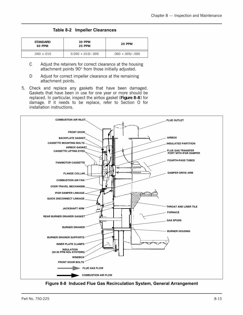
Chapter 8 — Inspection and Maintenance
Table 8-2 Impeller Clearances
C Adjust the retainers for correct clearance at the housing attachment points 90° from those initially adjusted.
D Adjust for correct impeller clearance at the remaining attachment points.
5. Check and replace any gaskets that have been damaged.Gaskets that have been in use for one year or more should bereplaced. In particular, inspect the airbox gasket (Figure 8-8) fordamage. If it needs to be replace, refer to Section O forinstallation instructions.
STANDARD60 PPM
30 PPM25 PPM
20 PPM
.040 ±.010 0.050 +.010/–.005 .060 +.005/–.000
Figure 8-8 Induced Flue Gas Recirculation System, General Arrangement
COMBUSTION AIR INLET
FRONT DOOR
CASSETTE MOUNTING BOLTS
AIRBOX GASKET
CASSETTE LIFTING EYES
FAN/MOTOR CASSETTE
FLANGE COLLAR
COMBUSTION AIR FAN
OVER-TRAVEL MECHANISM
IFGR DAMPER LINKAGE
QUICK DISCONNECT LINKAGE
JACKSHAFT ARM
BURNER DRAWER
BURNER DRAWER SUPPORTS
INNER PLATE CLAMPS
FRONT DOOR BOLTS
FLUE OUTLET
AIRBOX
FLUE GAS TRANSFERPORT WITH IFGR DAMPER
FOURTH-PASS TUBES
DAMPER DRIVE ARM
THROAT AND LINER TILE
FURNACE
GAS SPUDS
BURNER HOUSING
FLUE GAS FLOW
COMBUSTION AIR FLOW
BACKPLATE GASKET
WINDBOX
INSULATED PARTITION
REAR BURNER DRAWER GASKET
INSULATION (20-30 PPM NOx SYSTEMS)
Part No. 750-225 8-15
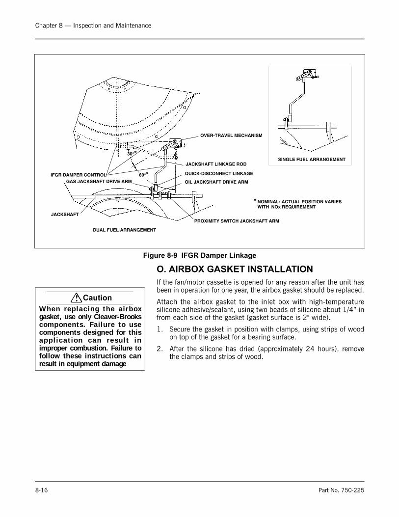
Chapter 8 — Inspection and Maintenance
O. AIRBOX GASKET INSTALLATION
If the fan/motor cassette is opened for any reason after the unit hasbeen in operation for one year, the airbox gasket should be replaced.
Attach the airbox gasket to the inlet box with high-temperaturesilicone adhesive/sealant, using two beads of silicone about 1/4” infrom each side of the gasket (gasket surface is 2" wide).
1. Secure the gasket in position with clamps, using strips of woodon top of the gasket for a bearing surface.
2. After the silicone has dried (approximately 24 hours), removethe clamps and strips of wood.
Figure 8-9 IFGR Damper Linkage
SINGLE FUEL ARRANGEMENT
IFGR DAMPER CONTROL
JACKSHAFT
GAS JACKSHAFT DRIVE ARM
DUAL FUEL ARRANGEMENT
30°*
60°*
OVER-TRAVEL MECHANISM
JACKSHAFT LINKAGE ROD
QUICK-DISCONNECT LINKAGE
OIL JACKSHAFT DRIVE ARM
PROXIMITY SWITCH JACKSHAFT ARM
* NOMINAL: ACTUAL POSITION VARIES NOx REQUIREMENTWITH
! Caution
When replac ing the a i rboxgasket, use only Cleaver-Brookscomponents. Failure to usecomponents designed for thisapp l i ca t i on can resu l t inimproper combustion. Failure tofollow these instructions canresult in equipment damage
8-16 Part No. 750-225

Chapter 8 — Inspection and Maintenance
P. FAN/MOTOR CASSETTE INSTALLATION
The fan/motor cassette can be closed as follows:
1. Check that all adjustment screws are tight, and check thelinkage and IFGR damper for free movement before closing theunit.
2. Position the cassette into the front door.
3. Slide the cassette into position until it begins to contact the inletgasket (Figure 8-8) then measure the clearance between thecassette flange and the front door mounting face. There must beclearance of at least 1/4" to provide adequate gasketcompression when the cassette is mounted tightly to the door.
4. Secure the cassette with the fastening nuts.
5. After the cassette has been secured to the front head, reconnectthe davit to the front door by screwing in the retaining bolt at thetop centerline.
Figure 8-10 Fan / Motor Cassette
Figure 8-11 Jackshaft Linkage Settings
JACKSHAFT LINKAGE ROD
GAS JACKSHAFT DRIVE ARM
QUICK DISCONNECT LINKAGE
OIL JACKSHAFT DRIVE ARM
PROXIMITY SWITCH AND DRIVE ARM(COMBINATION GAS & OIL SYSTEMS ONLY)
2”2-3/4”
GAS JACKSHAFT DRIVE ARM
OIL JACKSHAFT DRIVE ARM
40°
20°
THE IFGR SYSTEM CAN BE EQUIPPED WITH
EITHER A SINGLE OR DUAL LINKAGE ARM,
DEPENDING ON THE NUMBER OF FUELS
USED AND THE NOX LEVELS DESIRED. ALL
SINGLE-FUELED BOILERS HAVE A SINGLE
DRIVE ARM/ DUAL-FUELED BOILERS MAY OR
MAY NOT HAVE A DUAL ARM, DEPENDING ON
JACKSHAFT LINKAGE ROD POSITION LABEL
JACKSHAFT LINKAGE ROD
! Warning
Do not remove the davit arm assembly from the motor/fancassette without first verifying that the cassette is securelybolted to the boiler. Failure to follow these instructions canresult in serious personal injury or death.
Part No. 750-225 8-17
Chapter 8 — Inspection and Maintenance
Check occasionally that the fan is securely tightened to the motorshaft. Check the clearance between the fan vanes and housing asoutlined above.
Q. SAFETY VALVESThe safety valve is a very important safety device and deservesattention accordingly.
Follow the recommendations of your boiler inspector regardingvalve inspection and testing. The frequency of testing, either by theuse of the lifting lever or by raising the steam pressure, should bebased on the recommendation of your boiler inspector and/or thevalve manufacturer, and in accordance with sections VI and VII ofthe ASME Boiler and Pressure Vessel Code.
Avoid excessive operation of the safety valve; even one opening canprovide a means of leakage. Safety valves should be operated onlyoften enough to assure that they are in good working order. When apop test is required, raise the operating pressure to the set pressureof the safety valve, allowing it to open and reseat as it would innormal service.
Do not hand operate the valve with less than 75% of the stampedset pressure exerted on the underside of the disc. When handoperating, be sure to hold the valve in an open position long enoughto purge accumulated foreign material from the seat area and thenallow the valve to snap shut.
Frequent usage of the safety valve will cause the seat and disc tobecome wire drawn or steam cut. This will cause the valve to leakand necessitate down time of the boiler for valve repair orreplacement. Repair of a valve must be done only by themanufacturer or his authorized representative.
Avoid having the operating pressure too near the safety valve setpressure. A 10% differential is recommended. An even greaterdifferential is desirable and will assure better seat tightness andvalve longevity.
R. FUEL OIL METERING VALVE, ADJUSTING AND RELIEF VALVES
In the event that a leak occurs in the packing of the metering valve,the packing nut should be snugged gradually to stop the leak.
If replacement of the metering valve packing is necessary, procurekit P/N 880-370 and install in accordance with the followingprocedure.
1. Shut off the oil flow. Be sure no pressure shows on the gauge.
2. Match-mark the cam hub and drive shaft. Match marking willenable replacement of the cam in its original position and resultin a minimum of cam adjustment when the burner is refired.
3. Clamp or hold the metering stem in the down position.
! Caution
Do not over tighten the metering valve packing nut. Excessive tightening of the packing nut prevents free movement of the metering stem. Failure to follow these instructions can cause damage to the equipment.
8-18 Part No. 750-225
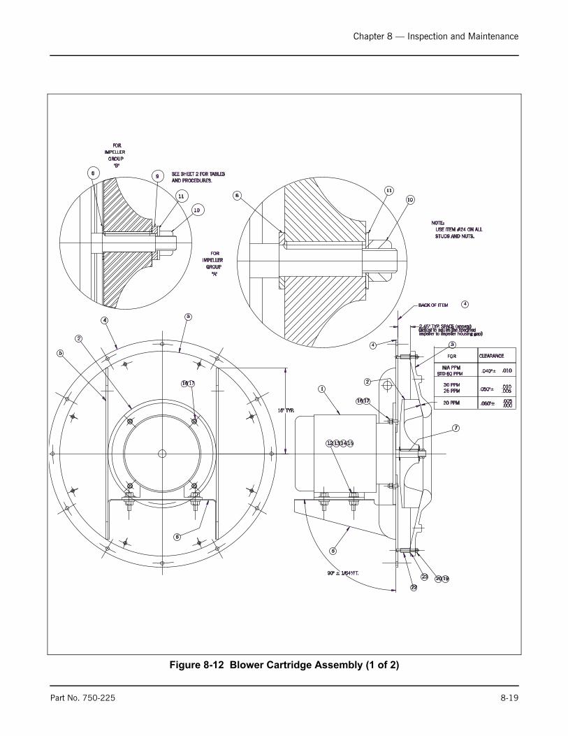
Chapter 8 — Inspection and Maintenance
Figure 8-12 Blower Cartridge Assembly (1 of 2)
5
2
43
15" TYP.
1716
6
4
BACK OF ITEM 4
2
17
12 13 14 15
6
22
20 19
3
7
FGR CLEARANCE
16
1
90° ± 1/64"/FT.
2.45" TYP. SPACE (approx)
23
811
10
SEE SHEET 2 FOR TABLESAND PROCEDURES.
.050"±
.040"±
25 PPM30 PPM
STD 60 PPMN/A PPM
.010
.010
.005
(adjust to aquire the specifiedimpeller to impeller housing gap)
20 PPM .005.000.060"±
NOTE: USE ITEM #24 ON ALL STUDS AND NUTS.
10
11
98
FORIMPELLER
GROUP"B"
"A"
GROUPIMPELLER
FOR
Part No. 750-225 8-19

Chapter 8 — Inspection and Maintenance
3
2 IMPELLER - OPEN TYPE
1
DESCRIPTIONPART NO.QTYITEM
4
5
8
6
BLOWER MOTER
HOUSING - IMPELLER
TABLE
40-C-6021
1
10
10
869-00180
12
12
11
1 869-00177
868-95
NUT,JAMB-RH. SELF LOCK.(1-1/4"-12 UNF)
869-00030 NUT, HEX, 3/8"-16
LOCKWASHER, 3/8"952-00093
19
20
019-01398
952-176
WASHER, (1-1/4" ID X 2" OD)
CAPSCREW, HEX, HD. 1/2"-13
1 TABLE
8
8
1
4
4
1
8
8
1
WASHER, FLAT, 3/8" SAE TYPE
NUT, COUPLING, 3/8"-16 X 1-3/4" LG
952-00106
869-00101
003-1277 BASE ASSY, MOUNTING-"LE"
23
22
USED ON
- - -
1 085-03120 SUPPORT, MOTOR (085-03120)
SPACER- 1/2 THK. (077-B-00432) 077-001021 10-30 MTR H.P.
30-40 ODP MTR H.P.
NUT,JAMB-RH. SELF LOCK.(1-3/8"-12 UNF)
10-30 MTR H.P.
40-75 MTR H.P.
50-75 ODP MTR H.P.SUPPORT, MOTOR085-0312116
30-40 MTR H.P.(D.P.)
30 MTR H.P. (TEFC)
50-75 MTR H.P. (D.P.)
40-75 MTR H.P. (TEFC)
40-75 MTR H.P. (TEFC)
50-75 MTR H.P. (D.P.)
30 MTR H.P. (TEFC)
30-40 MTR H.P.(D.P.)
4
4 NUT, HEX, 1/2"-13869-00015
NUT, HEX, 5/8"-11869-00017
13
13
CAPSCREW, HEX, HD. 5/8"-11
14
14
952-00101 WASHER, 5/8"
952-00108 WASHER, 1/2"4
4
30-40 MTR H.P.(D.P.)
30 MTR H.P. (TEFC)
50-75 MTR H.P. (D.P.)40-75 MTR H.P. (TEFC)
40-75 MTR H.P. (TEFC)
50-75 MTR H.P. (D.P.)
30 MTR H.P. (TEFC)
30-40 MTR H.P.(D.P.)
4
4 LOCKWASHER, 1/2"952-00094
LOCKWASHER, 5/8"952-00084
15
15
16
16
869-00018 NUT, HEX, 3/4"
869-00015 NUT, HEX, 1/2"4
4
0-15 MTR H.P.(D.P.)
0-10 MTR H.P. (TEFC)
20-75 MTR H.P. (D.P.)
15-75 MTR H.P. (TEFC)
15-75 MTR H.P. (TEFC)
20-75 MTR H.P. (D.P.)
0-10 MTR H.P. (TEFC)
0-15 MTR H.P.(D.P.)
4
4 LOCKWASHER, 1/2"952-00094
LOCKWASHERS, 3/4"952-00095
17
17
-
-
-
-
-
-
-
-
BASE ASSY, MOUNTING-"LE" 003-B-127614
BASE ASSY, MOUNTING-"LE" 003-127814
7.5-15 MTR H.P.(D.P.)
7.5-10 MTR H.P. (TEFC)
15-30 MTR H.P. (TEFC)
20-40 MTR H.P.(D.P.)
50-75 MTR H.P.(D.P.)
40-75 MTR H.P. (TEFC)
-24 887-27 LUBRICANT, RUST PREVENTATIVE5oz
KEY (5/16" SQ. X 2-1/2" LG.)841-0110517 10-75 MTR H.P.
40-75 MTR H.P.
10-30 MTR H.P.
SPACER- 5/16" THK. (077-B-00432)
1 077-00479 SPACER- 5/16" THK. (077-B-00432)
077-004801
8
8GROUP "B"
FOR IMPELLER
FOR IMPELLER
GROUP "A"
OPTION
A7IA
ICIG
IGICIAA7
SUPPORT, MOTOR (085-03144)085-031446 1 60-75 TEFC MTR H.P.
40-50 TEFC MTR H.P.
SPACER- 5/16" THK. (077-B-00432)
SPACER- 5/16" THK. (077-B-00432)
FOR IMPELLER
GROUP "B" 952-004809 1
077-004799 1
40-75 MTR H.P.
10-30 MTR H.P.
30 TEFC MTR H.P.
11 1 019-01362
10-30 MTR H.P.
WASHER, (1-3/8" ID X 2.4" OD) 40-75 MTR H.P.
4 1 003-2077 BASE ASSY, MOUNTING-"CBR"
BASE ASSY, MOUNTING-"CBR" 003-207814
BASE ASSY, MOUNTING-"CBR" 003-200014
7.5-15 MTR H.P.(D.P.)
7.5-10 MTR H.P. (TEFC)
15-30 MTR H.P. (TEFC)
20-40 MTR H.P.(D.P.)
50-75 MTR H.P.(D.P.)
40-75 MTR H.P. (TEFC)
Figure 8-12. Blower Cartridge Assembly (2 of 2)
8-20 Part No. 750-225

Chapter 8 — Inspection and Maintenance
Figure 8-13 Flange Collar and Damper Settings (Top View)
Figure 8-14 Overtravel Linkage Settings
D._____ HOLE POSITION NUMBER
“A”
“D”
FLANGE COLLAR
HOLE #1
HOLE #2
LINKAGE CONNECTION POINT
DAMPERSHOWN IN THE LOW-FIRE POSITION
“B”
“C”NOTE: RECORD “INSTALLED”VALUES ON THIS ILLUSTRATIONFOR FUTURE REFERENCE.
A._____ FLANGE COLLAR SETTINGB._____ DAMPER POSITION AT LOW-FIREC._____ DAMPER LINKAGE ARE ANGLE (DEGREES)
LOW-FIRE STOP SCREW
DOUBLE SPRINGS
HOLE #1 (FAST OPENING DAMPER)
HIGH-FIRE STOP SCREW
EXTERNAL ARM
(SLOW-OPENING DAMPER)HOLE #5 (SLOW -OPENING DAMPER)
HOLE #1
INTERNAL ARM
90°HOLE # 8
(FAST OPENING DAMPER)
(FACTORY SETTING AND RECOMMENDEDINITIAL SETTING FOR INTERNAL ARM
“A”
“B”
HOLE POSITION
IN ALL CASES)
EXTERNAL ARM
NOTE: RECORD “INSTALLED”VALUES ON THIS ILLUSTRATIONFOR FUTURE REFERENCE.
A._____ EXTERNAL ARM HOLE POSITIONB._____ DEGREES
Part No. 750-225 8-21
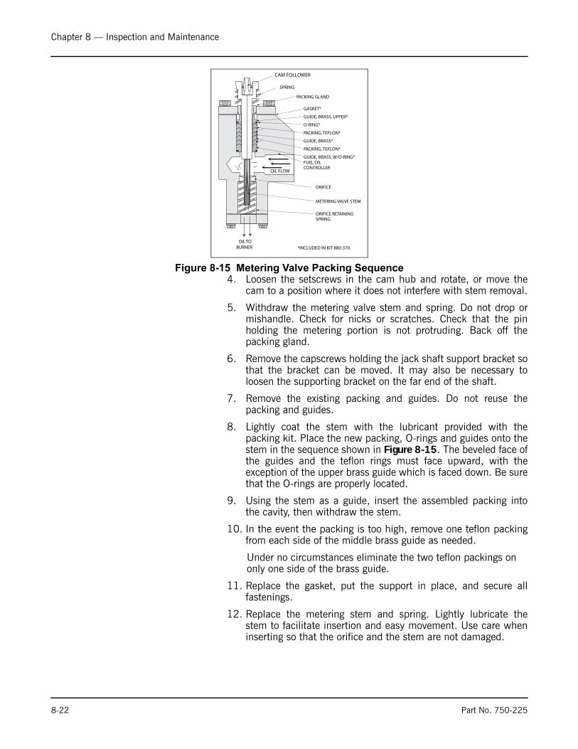
Chapter 8 — Inspection and Maintenance
4. Loosen the setscrews in the cam hub and rotate, or move thecam to a position where it does not interfere with stem removal.
5. Withdraw the metering valve stem and spring. Do not drop ormishandle. Check for nicks or scratches. Check that the pinholding the metering portion is not protruding. Back off thepacking gland.
6. Remove the capscrews holding the jack shaft support bracket sothat the bracket can be moved. It may also be necessary toloosen the supporting bracket on the far end of the shaft.
7. Remove the existing packing and guides. Do not reuse thepacking and guides.
8. Lightly coat the stem with the lubricant provided with thepacking kit. Place the new packing, O-rings and guides onto thestem in the sequence shown in Figure 8-15. The beveled face ofthe guides and the teflon rings must face upward, with theexception of the upper brass guide which is faced down. Be surethat the O-rings are properly located.
9. Using the stem as a guide, insert the assembled packing intothe cavity, then withdraw the stem.
10. In the event the packing is too high, remove one teflon packingfrom each side of the middle brass guide as needed.
Under no circumstances eliminate the two teflon packings on only one side of the brass guide.
11. Replace the gasket, put the support in place, and secure allfastenings.
12. Replace the metering stem and spring. Lightly lubricate thestem to facilitate insertion and easy movement. Use care wheninserting so that the orifice and the stem are not damaged.
Figure 8-15 Metering Valve Packing Sequence
OIL TOBURNER
CAM FOLLOWER
SPRING
PACKING GLAND
GASKET*
GUIDE, BRASS, UPPER*
O-RING*
PACKING, TEFLON*
GUIDE, BRASS*
PACKING, TEFLON*
GUIDE, BRASS, W/O-RING*FUEL OILCONTROLLER
ORIFICE
METERING VALVE STEM
ORIFICE RETAININGSPRING
*INCLUDED IN KIT 880-370
OIL FLOW
8-22 Part No. 750-225

Chapter 8 — Inspection and Maintenance
13. Snug the packing gland, but only sufficiently to place slighttension on the packing. The stem must move freely from theforce of the spring.
14. Work the stem up and down several times to ensure that it ismoves freely.
15. Depress the valve stem and replace the cam. Mate the match-marks and secure the setscrews. Be sure the cam spring iscentered in the roller.
16. Restore oil flow. Test fire the burner at various firing rates beingcertain that the metering stem freely follows the cam.
17. Tighten the packing gland after a period of operation, ifnecessary, to maintain proper tension on the packing. Do notovertighten.
If there are indications that the oil metering valve has becomeclogged at its orifice, it will be necessary to disassemble the controlto remove the obstruction. Clean the slotted stem of the oil meteringvalve with suitable solvent and blow-dry with an air line. Follow theprocedure outlined above when removing or reinstalling themetering valve stem. Also check all fuel line strainers.
Should a pressure adjusting or relief valve become clogged,disassemble by releasing the locknut and backing off the screw torelieve tension on diaphragm. Remove the valve cover and thediaphragm to expose any dirt or foreign material which may haveentered the valves. Clean out carefully and reassemble. It isrecommended that the diaphragms be replaced annually.
S. THE AIR PUMP AND LUBRICATING SYSTEM
Air Compressor
The air pump itself requires little maintenance. However, the life ofthe pump is dependent upon a sufficient supply of clean coollubricating oil. The oil level in the air-oil tank must be observedclosely. Lack of oil will damage the pump making replacementnecessary. Disassembly or field repairs to the pump are notrecommended.
Lubricating Oil
Lubricating oil must be visible in the gauge glass at all times. Thereis no specific level required as long as oil is visible. Do not operateif oil is not visible.
Figure 8-16 Air Compressor Module
Part No. 750-225 8-23

Chapter 8 — Inspection and Maintenance
Oil with proper viscosity must be used. SAE 20 detergent isrecommended, although SAE 10 detergent is also permissible.
When adding oil:
Remove the cover from the fill pipe and add oil through the conicalstrainer in the pipe with the unit running.
The oil and its container should be clean. Although there is astrainer in the lube oil line, its purpose is to remove any unwantedmaterials rather than to act as a filter for unclean oil.
Lubricating Oil Strainer and Cooling Coil
Air pressure from the pump forces lubricating oil from the tankthrough a cooling coil to the pump. The oil lubricates the pumpbearings and also provides a seal and lubrication for the pumpvanes.
The cooled oil flows to the pump through the strainer in the fillerpipe. It is possible to visually verify oil flow during operation byremoving the filler cap and checking the flow. If necessary, thestrainer may be cleaned during operation.
In the event it is necessary to clean the strainer during operation,clean it and replace immediately. It can be cleaned by immersing insolvent and blowing it dry with compressed air. Do not operatewithout the strainer any longer than necessary, and never add newoil unless it is in place. A spare strainer basket can be obtained, ifdesired, and used on a rotating basis while the other is serviced.
Air Cleaner
Never operate the air pump without the air cleaner in place. Thecleaner itself must be periodically checked and its element flushedand cleaned semi-annually.
Air-Oil Tank
Pads of steel wool are used in the air to oil tank as a filteringmedium to separate the lube oil from the compressed air. Figure 8-17 shows a cross-section of a tank and the location of the steelwool.
! Caution
Oil must NEVER be added unlessthe pump is in operation and thestrainer screen is in place.Fa i lu re to f o l l ow theseinstructions can cause damage tothe equipment.
8-24 Part No. 750-225

Chapter 8 — Inspection and Maintenance
The pads play a very important role and should be replaced semi-annually. It is also important that a proper grade of steel wool beused. Only No. 3 coarse grade American steel wool or equal(CB919-124) should be used. Three pads are required. Whenreplacing the wool, insert two pads into the cylinder. Alternate thegrain of the pads. Install the spacer with its stub end toward theopening and fit one pad over the stub. Be careful not to overlycompress the wool and be sure that it is fluffed out to fill allavailable space. Improper packing can cause high oil consumptionAfter the last pad is in place, slip the retainer screen onto thecylinder. Be sure to fit an O-ring gasket under the cover so that atight seal is obtained.
Follow previous instructions for oil replacement.
Lube Oil Cooling Coil
The fins on the tubing must be kept clean and free of any dust ordirt that would resist air flow and cause overheating. Use an airhose to blow away debris. Internal cleaning of the tubes is seldomrequired if a good quality lube oil is used.
Flexible Coupling Alignment
Alignment of the pump and motor through the flexible coupling isextremely important for trouble-free operation. Check the couplingalignment semi-annually and replace the coupling insert asrequired. Keep the coupling guard in place.
The most commonly used tools for checking alignment are a smallstraightedge and a thickness gauge (Figure 8-18).
The coupling must be checked for both parallel (offset) alignmentand angular (gap) alignment. Parallel misalignment exists whenshaft axes are parallel but not concentric (see Figure 8-18). Angularmisalignment is the reverse situation - shaft axes concentric, but notparallel.
Checking parallel alignment, both horizontal and vertical can beaccomplished, by laying a straightedge across the coupling halvesand checking with a thickness gauge to obtain the amount ofmisalignment. The check should be done on the top of the couplingand at 90 degrees. A useful hint is to hold a flashlight behind thestraightedge so that any gap can readily be seen.
Shim stock of appropriate thickness and area is then used undereither the feet of the pump or the motor to establish parallelalignment. A tolerance of .008" is a permissible limit.
After parallel alignment is established, check for angular alignment,which is done by checking the gap between coupling halves. Thecoupling should have a minimum gap of 1/16" and a maximum of3/32".
Set the spacing between the halves at one point by using athickness gauge and then rotate the coupling slowly to be sure thatclearance at that point remains the same through 360 degrees ofrotation. Adjust to obtain proper gap by loosening the hold-downbolts and shifting either the pump or the motor as required.
Figure 8-17 Air Oil Receiver Tank
AIR AND OILMIXTURE FROM
PUMPAIR TO NOZZLE
STEEL WOOLPADS (3)
(COARSE GRADE)
O-RING GASKET
SEPARATED OILLUBE OIL
LUBE OILTO COOLING COIL
AND PUMP
Figure 8-18 Coupling Alignment
OFFSETMISALIGNMENT
ANGULARMISALIGNMENT
Part No. 750-225 8-25
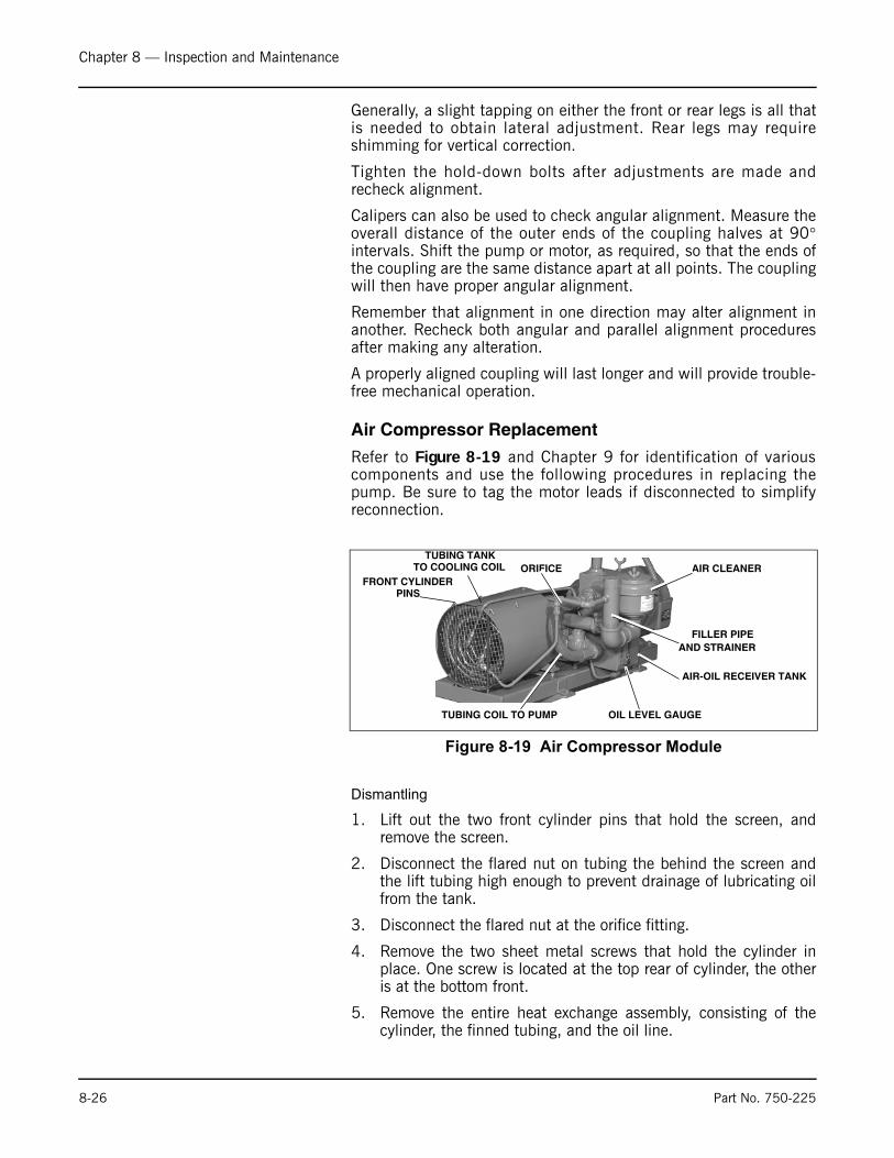
Chapter 8 — Inspection and Maintenance
Generally, a slight tapping on either the front or rear legs is all thatis needed to obtain lateral adjustment. Rear legs may requireshimming for vertical correction.
Tighten the hold-down bolts after adjustments are made andrecheck alignment.
Calipers can also be used to check angular alignment. Measure theoverall distance of the outer ends of the coupling halves at 90°intervals. Shift the pump or motor, as required, so that the ends ofthe coupling are the same distance apart at all points. The couplingwill then have proper angular alignment.
Remember that alignment in one direction may alter alignment inanother. Recheck both angular and parallel alignment proceduresafter making any alteration.
A properly aligned coupling will last longer and will provide trouble-free mechanical operation.
Air Compressor Replacement
Refer to Figure 8-19 and Chapter 9 for identification of variouscomponents and use the following procedures in replacing thepump. Be sure to tag the motor leads if disconnected to simplifyreconnection.
Dismantling
1. Lift out the two front cylinder pins that hold the screen, andremove the screen.
2. Disconnect the flared nut on tubing the behind the screen andthe lift tubing high enough to prevent drainage of lubricating oilfrom the tank.
3. Disconnect the flared nut at the orifice fitting.
4. Remove the two sheet metal screws that hold the cylinder inplace. One screw is located at the top rear of cylinder, the otheris at the bottom front.
5. Remove the entire heat exchange assembly, consisting of thecylinder, the finned tubing, and the oil line.
Figure 8-19 Air Compressor Module
FRONT CYLINDER PINS
TUBING TANKTO COOLING COIL ORIFICE AIR CLEANER
FILLER PIPE
AND STRAINER
AIR-OIL RECEIVER TANK
TUBING COIL TO PUMP OIL LEVEL GAUGE
8-26 Part No. 750-225

Chapter 8 — Inspection and Maintenance
6. Remove the fan from the air pump.
7. Disconnect the flexible air line from the lube tank.
8. Remove the coupling guard by pushing in on both sides until itclears the clamp.
9. Loosen the clamp at the rear of the tank and remove the tankwith copper tubing attached.
10. Leave the rear pump bracket (coupling end) in place to aid inrealignment of the replacement pump. Do this by removing thetwo capscrews that extend through the bracket into the pumphousing. Temporarily leave the front bracket attached to thepump.
11. Remove screws holding the front bracket to the base and lift offthe pump with its attachments. Note the location of the pipefittings and brackets prior to removing for installation on thereplacement pump. If piping is dismantled, be sure that thecheck valve is reinstalled so that the gate swings towards thepump.
Reassembly
Reassembly in reverse order of disassembly. With the rear pumpbracket left in place, realignment and spacing between the pumpshaft and the motor shaft is greatly simplified.
There should be approximately 7/8” space between the two shafts.Place the coupling insert between the coupling halves prior toreassembly. Check that both shafts rotate freely.
Refer to the previous section on coupling alignment instructions.
If shims were used originally under either pump brackets or motorfeet, be sure that they are correctly reinstalled.
When reinstalling the fan, slide the hub on the pump shaft so thatit is bottomed. Tighten the setscrew and cap screws. If the fanblades were removed from the hub, be sure that the side of theblade marked “Blower” faces the hub when reassembling. Whentightening the coupling halves or the fan hub, tighten the setscrewsagainst the key first, then tighten the setscrew against the shaft.Clean or remove any dust or grime from the blades prior toreinstalling.
When replacing the retainer screen, a slight force may be requiredto push the cooling coil into the air cylinder so that the pins may befitted into place.
Be sure that all piping connections are tight.
If the motor was replaced or if motor leads were disconnected, besure that pump rotation is proper before starting operation. The airpump should rotate in a clockwise direction, as viewed from thedrive shaft end.
Part No. 750-225 8-27

Chapter 8 — Inspection and Maintenance
General
Keep the motor and other components free from dust and dirt toprevent overheating and damage. Motor lubrication should followmanufacturer’s recommendations.
T. REFRACTORYThe boiler is shipped with completely installed refractory. Therefractory consists of the rear head (Figure 8-24), the inner door,and the furnace liner (Figure 8-25). Normal maintenance requireslittle time and expense, and prolongs the operating life of therefractory.
Preventive maintenance through periodic inspection will keep theoperator informed of the condition of the refractory, and will guardagainst unexpected and unwanted downtime and major repairs.
Frequent wash coating of the refractory surfaces is recom-mended.High-temperature-bonding, air-dry type mortar, diluted with waterto the consistency of light cream, is used for wash coating.Recoating intervals will vary with operating loads and are bestdetermined by the operator when the boiler is opened for inspection.
Furnace Liner
Maintenance consists of occasional wash coating of the entire liner.Face all joints or cracks by applying high temperature bondingmortar with a trowel or fingertips. Wash coating should be done assoon as cracks are detected.
Should segments of the liner burn away or fall out, replace the entirerefractory. Any refractory that may break out should be removed assoon as detected so that it will not fuse to the bottom of the furnaceand obstruct the flame.
If replacement is necessary, refer to Chapter 9 and order properreplacement materials. Remove existing refractory. Thoroughlyclean the furnace to remove all old refractory cement or otherforeign material to ensure the new liner seats firmly against thesteel. Inspect the furnace metal.
Depending upon the design pressure of the boiler, the furnace maybe of the corrugated type. It is necessary to fill in the corrugationvalleys under the furnace liner tile from 4 o’clock to 8 o’clock withinsulating cement. The liner tile should be fitted tightly against thecrown of the corrugation.
Figure 8-20 Throat Tile
Figure 8-21 Liner Tile
8-28 Part No. 750-225

Chapter 8 — Inspection and Maintenance
Throat Tile and Liner Installation
The furnace lining is shown in Figure 8-21. The throat tile (Figure8-20) must be installed to maintain an approximately 16” insidediameter, and be centered in the furnace. Since the thickness of thefurnace metal varies with the boiler design pressure, a shim ofappropriate thickness must be used to compensate for the variance.A layer or two of insulating board or equal, or a bed of refractorymaterial, may be used to center the ring.
The liner tile can be fitted tightly against the furnace, since thefinished diameter is not critical.
It is recommended that the tile be dry-fitted, match-marked,removed, and then reinstalled with the proper amount of refractorycement. Thin joints (less than 1/16”) are desirable. Generally, it willbe necessary to shave a portion from one or more tiles to obtain afit. If a fill piece is required, cut it to fit and install the piece at thebottom of the furnace.When installing the housing, or the tileagainst the housing, liberally coat the surface with refractorycement. Remove any cement that is squeezed out.
Allow refractory to air dry as long as possible. If immediate use isrequired, fire intermittently at a low rate for several hours tothoroughly dry the refractory.
For detailed information, request Bulletin C10-5921 from your localCleaver-Brooks Representative.
Installation Procedures
The following procedure is typical for all standard 96" diameterboilers with the exception of Items #6, 7, and 8, not used for any
Notice
The area between the burnerhousing and the throat tilerequi res a good seal . Animproper or poor seal allowsa i r l eaks that can causeoverheating and burning of theburner housing metal. The areashould be inspected semi-annually. Contact you localCleaver-Brooks representativefor information and service
Figure 8-22 Furnace Liner Refractory - 400 to 800 hp
FURNACE
BURNERHOUSING
BOILER SHELL
COAT OR FILL THIS AREAWITH MOTOR ANDINSULATING CEMENT
GASKETFURNACE(32-981)
USE 1/4" "CERAFORM" OR EQUALAS A FILLER TO OBTAIN 16" ± 1/8"ID OF THROAT TILE
FURNACE LINER TILE(94-205)
Part No. 750-225 8-29
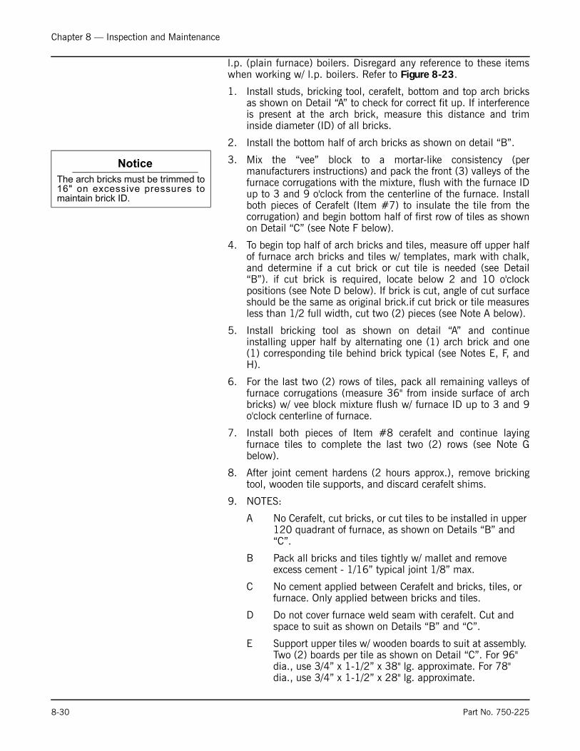
Chapter 8 — Inspection and Maintenance
l.p. (plain furnace) boilers. Disregard any reference to these itemswhen working w/ l.p. boilers. Refer to Figure 8-23.
1. Install studs, bricking tool, cerafelt, bottom and top arch bricksas shown on Detail “A” to check for correct fit up. If interferenceis present at the arch brick, measure this distance and triminside diameter (ID) of all bricks.
2. Install the bottom half of arch bricks as shown on detail “B”.
3. Mix the “vee” block to a mortar-like consistency (permanufacturers instructions) and pack the front (3) valleys of thefurnace corrugations with the mixture, flush with the furnace IDup to 3 and 9 o'clock from the centerline of the furnace. Installboth pieces of Cerafelt (Item #7) to insulate the tile from thecorrugation) and begin bottom half of first row of tiles as shownon Detail “C” (see Note F below).
4. To begin top half of arch bricks and tiles, measure off upper halfof furnace arch bricks and tiles w/ templates, mark with chalk,and determine if a cut brick or cut tile is needed (see Detail“B”). if cut brick is required, locate below 2 and 10 o'clockpositions (see Note D below). If brick is cut, angle of cut surfaceshould be the same as original brick.if cut brick or tile measuresless than 1/2 full width, cut two (2) pieces (see Note A below).
5. Install bricking tool as shown on detail “A” and continueinstalling upper half by alternating one (1) arch brick and one(1) corresponding tile behind brick typical (see Notes E, F, andH).
6. For the last two (2) rows of tiles, pack all remaining valleys offurnace corrugations (measure 36" from inside surface of archbricks) w/ vee block mixture flush w/ furnace ID up to 3 and 9o'clock centerline of furnace.
7. Install both pieces of Item #8 cerafelt and continue layingfurnace tiles to complete the last two (2) rows (see Note Gbelow).
8. After joint cement hardens (2 hours approx.), remove brickingtool, wooden tile supports, and discard cerafelt shims.
9. NOTES:
A No Cerafelt, cut bricks, or cut tiles to be installed in upper 120 quadrant of furnace, as shown on Details “B” and “C”.
B Pack all bricks and tiles tightly w/ mallet and remove excess cement - 1/16” typical joint 1/8” max.
C No cement applied between Cerafelt and bricks, tiles, or furnace. Only applied between bricks and tiles.
D Do not cover furnace weld seam with cerafelt. Cut and space to suit as shown on Details “B” and “C”.
E Support upper tiles w/ wooden boards to suit at assembly. Two (2) boards per tile as shown on Detail “C”. For 96" dia., use 3/4” x 1-1/2” x 38" lg. approximate. For 78" dia., use 3/4” x 1-1/2” x 28" lg. approximate.
Notice
The arch bricks must be trimmed to16" on excessive pressures tomaintain brick ID.
8-30 Part No. 750-225
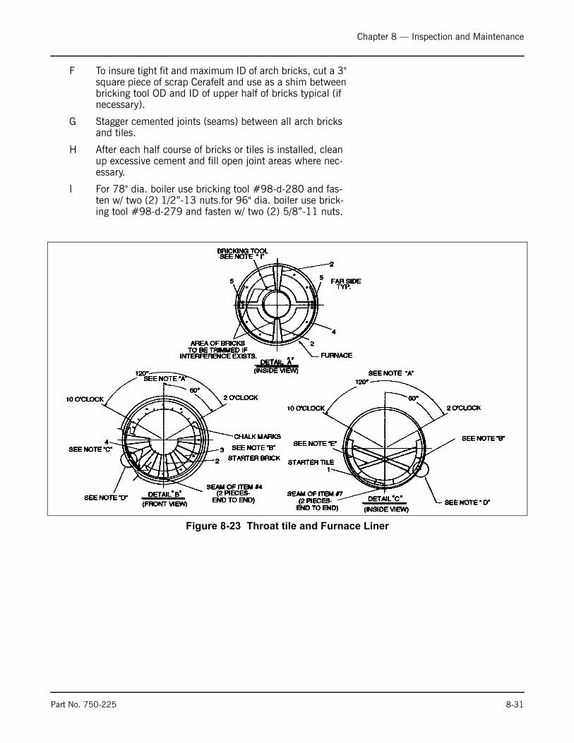
Chapter 8 — Inspection and Maintenance
F To insure tight fit and maximum ID of arch bricks, cut a 3" square piece of scrap Cerafelt and use as a shim between bricking tool OD and ID of upper half of bricks typical (if necessary).
G Stagger cemented joints (seams) between all arch bricks and tiles.
H After each half course of bricks or tiles is installed, clean up excessive cement and fill open joint areas where nec-essary.
I For 78" dia. boiler use bricking tool #98-d-280 and fas-ten w/ two (2) 1/2”-13 nuts.for 96" dia. boiler use brick-ing tool #98-d-279 and fasten w/ two (2) 5/8”-11 nuts.
Figure 8-23 Throat tile and Furnace Liner
Part No. 750-225 8-31
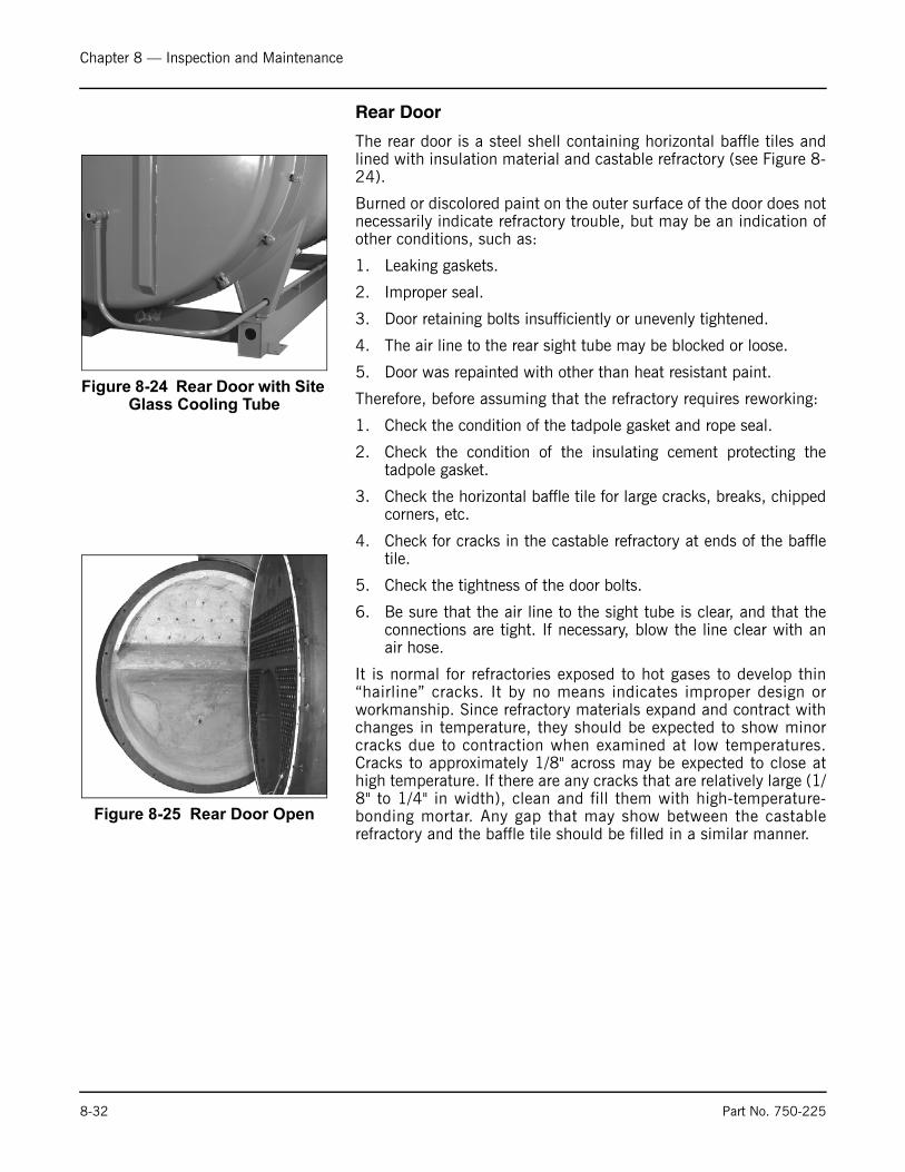
Chapter 8 — Inspection and Maintenance
Rear Door
The rear door is a steel shell containing horizontal baffle tiles andlined with insulation material and castable refractory (see Figure 8-24).
Burned or discolored paint on the outer surface of the door does notnecessarily indicate refractory trouble, but may be an indication ofother conditions, such as:
1. Leaking gaskets.
2. Improper seal.
3. Door retaining bolts insufficiently or unevenly tightened.
4. The air line to the rear sight tube may be blocked or loose.
5. Door was repainted with other than heat resistant paint.
Therefore, before assuming that the refractory requires reworking:
1. Check the condition of the tadpole gasket and rope seal.
2. Check the condition of the insulating cement protecting thetadpole gasket.
3. Check the horizontal baffle tile for large cracks, breaks, chippedcorners, etc.
4. Check for cracks in the castable refractory at ends of the baffletile.
5. Check the tightness of the door bolts.
6. Be sure that the air line to the sight tube is clear, and that theconnections are tight. If necessary, blow the line clear with anair hose.
It is normal for refractories exposed to hot gases to develop thin“hairline” cracks. It by no means indicates improper design orworkmanship. Since refractory materials expand and contract withchanges in temperature, they should be expected to show minorcracks due to contraction when examined at low temperatures.Cracks to approximately 1/8" across may be expected to close athigh temperature. If there are any cracks that are relatively large (1/8" to 1/4" in width), clean and fill them with high-temperature-bonding mortar. Any gap that may show between the castablerefractory and the baffle tile should be filled in a similar manner.
Figure 8-24 Rear Door with Site Glass Cooling Tube
Figure 8-25 Rear Door Open
8-32 Part No. 750-225
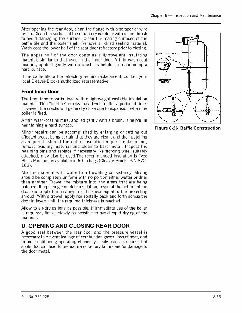
Chapter 8 — Inspection and Maintenance
After opening the rear door, clean the flange with a scraper or wirebrush. Clean the surface of the refractory carefully with a fiber brushto avoid damaging the surface. Clean the mating surfaces of thebaffle tile and the boiler shell. Remove all dried sealing material.Wash-coat the lower half of the rear door refractory prior to closing.
The upper half of the door contains a lightweight insulatingmaterial, similar to that used in the inner door. A thin wash-coatmixture, applied gently with a brush, is helpful in maintaining ahard surface.
If the baffle tile or the refractory require replacement, contact yourlocal Cleaver-Brooks authorized representative.
Front Inner Door
The front inner door is lined with a lightweight castable insulationmaterial. Thin “hairline” cracks may develop after a period of time.However, the cracks will generally close due to expansion when theboiler is fired.
A thin wash-coat mixture, applied gently with a brush, is helpful inmaintaining a hard surface.
Minor repairs can be accomplished by enlarging or cutting outaffected areas, being certain that they are clean, and then patchingas required. Should the entire insulation require replacement,remove existing material and clean to bare metal. Inspect theretaining pins and replace if necessary. Reinforcing wire, suitablyattached, may also be used.The recommended insulation is “VeeBlock Mix” and is available in 50 lb bags (Cleaver-Brooks P/N 872-162).
Mix the material with water to a troweling consistency. Mixingshould be completely uniform with no portion either wetter or drierthan another. Trowel the mixture into any areas that are beingpatched. If replacing complete insulation, begin at the bottom of thedoor and apply the mixture to a thickness equal to the protectingshroud. With a trowel, apply horizontally back and forth across thedoor in layers until the required thickness is reached.
Allow to air-dry as long as possible. If immediate use of the boileris required, fire as slowly as possible to avoid rapid drying of thematerial.
U. OPENING AND CLOSING REAR DOOR A good seal between the rear door and the pressure vessel isnecessary to prevent leakage of combustion gases, loss of heat, andto aid in obtaining operating efficiency. Leaks can also cause hotspots that can lead to premature refractory failure and/or damage tothe door metal.
Figure 8-26 Baffle Construction
Part No. 750-225 8-33
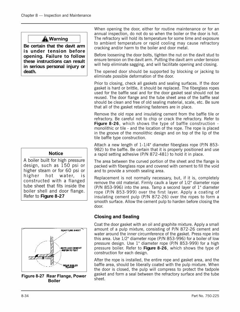
Chapter 8 — Inspection and Maintenance
When opening the door, either for routine maintenance or for anannual inspection, do not do so when the boiler or the door is hot.The refractory will hold its temperature for some time and exposureto ambient temperature or rapid cooling may cause refractorycracking and/or harm to the boiler and door metal.
Before loosening the door bolts, tighten the nut on the davit stud toensure tension on the davit arm. Putting the davit arm under tensionwill help eliminate sagging, and will facilitate opening and closing.
The opened door should be supported by blocking or jacking toeliminate possible deformation of the door.
Prior to closing, check all gaskets and sealing surfaces. If the doorgasket is hard or brittle, it should be replaced. The fiberglass ropesused for the baffle seal and for the door gasket seal should not bereused. The door flange and the tube sheet area of the baffle sealshould be clean and free of old sealing material, scale, etc. Be surethat all of the gasket retaining fasteners are in place.
Remove the old rope and insulating cement from the baffle tile orrefractory. Be careful not to chip or crack the refractory. Refer toFigure 8-26, which shows the type of baffle construction -monolithic or tile - and the location of the rope. The rope is placedin the groove of the monolithic design and on top of the lip of thetile baffle type construction.
Attach a new length of 1-1/4" diameter fiberglass rope (P/N 853-982) to the baffle. Be certain that it is properly positioned and usea rapid setting adhesive (P/N 872-481) to hold it in place.
The area between the curved portion of the sheet and the flange ispacked with fiberglass rope and covered with cement to fill the voidand to provide a smooth sealing area.
Replacement is not normally necessary, but, if it is, completelyremove the old material. Firmly caulk a layer of 1/2" diameter rope(P/N 853-996) into the area. Tamp a second layer of 1" diameterrope (P/N 853-999) over the first layer. Apply a coating ofinsulating cement pulp (P/N 872-26) over the ropes to form asmooth surface. Allow the cement pulp to harden before closing thedoor.
Closing and Sealing
Coat the door gasket with an oil and graphite mixture. Apply a smallamount of a pulp mixture, consisting of P/N 872-26 cement andwater around the inner circumference of the gasket. Press rope intothis area. Use 1/2" diameter rope (P/N 853-996) for a boiler of lowpressure design. Use 1" diameter rope (P/N 853-999) for a highpressure boiler. Refer to Figure 8-26, which shows the type ofconstruction for each design.
After the rope is installed, the entire rope and gasket area, and thebaffle area, should be liberally coated with the pulp mixture. Whenthe door is closed, the pulp will compress to protect the tadpolegasket and form a seal between the refractory surface and the tubesheet.
! Warning
Be certain that the davit armis under tens ion be fo reopening. Failure to followthese instructions can resultin serious personal injury ordeath.
Notice
A boiler built for high pressuredesign, such as 150 psi orhigher steam or for 60 psi orh ighe r ho t wa te r, i sconstructed with a flangedtube sheet that fits inside theboiler shell and door flange.Refer to Figure 8-27
Figure 8-27 Rear Flange, Power Boiler
8-34 Part No. 750-225

Chapter 8 — Inspection and Maintenance
Door bolts should be run in snug and tightened evenly to avoidcocking the door and damaging the gasket. Start tightening at topcenter and alternate between the top and bottom bolts until both aretight. Do not overtighten. Tighten alternate bolts until the door issecured and gas tight. After the boiler is back in operation, retightenthe bolts to compensate for any expansion. Loosen the nut on thedavit stud to release tension from the davit arm.
V. LUBRICATION
Electric Motors
Manufacturers of electric motors vary in their specifications forlubr ica t ion and care o f moto r bear ings ; the i r spec i f i crecommendations should be followed.
Ball-bearing-equipped motors are pre-lubricated. The length of timea bearing can run without having grease added will depend uponmany factors, including the rating of the motor, type of motorenclosure, duty, atmospheric conditions, humidity, and ambienttemperatures.
Figure 8-28 Rear Door Sealing
Part No. 750-225 8-35
Chapter 8 — Inspection and Maintenance
Complete renewal of grease, when necessary, can be accomplishedby forcing out the old grease with the new grease. Thoroughly wipethose portions of the housing around the filler and drain plugs(above and below bearings). Remove the drain plug (bottom) andfree the drain hole of any hardened grease which may haveaccumulated. With the motor not running, add new grease throughthe filler hole until clear grease starts to come out of the drain hole.Before replacing the drain plug, run the motor for 10 to 20 minutesto expel any excess grease.The filler and drain plugs should bethoroughly cleaned before they are replaced.
The lubricant used should be clean and equal to one of the goodcommercial grades of grease locally available. Some lubricants thatare distributed nationally are (See also Figure 8-3):
• Gulf Oil - Precision Grease No. 2
• Humble Oil - Andok B
• Texaco - Multifak No. 2
• Phillips - 1B + RB No.2
• Fiske Bros. - Ball Bearing Lubricant
• Standard/Mobil - Mobilux No. 2
Control Linkage
Apply a non-gumming, dripless, high temperature lubricant, such asgraphite or a silicone derivative to all pivot points and moving parts.Work lubricant in well and wipe excess. Repeat application atrequired intervals to maintain freedom of motion of parts.
Solenoid and Motorized Valves
Solenoid valves and motorized valves require no lubrication.
IFGR Lubrication
Motors should be lightly lubricated at startup, using the greasespecified below or equivalent. Lubricate the motor as follows:
Table 8-3 IFGR Maintenance Check List
Daily • Check visually for free movement of IFGR linkage.
Quarterly • Manually check for free movement of IFGR linkage.• Inspect and clean IFGR damper (oil-fueled system). • Inspect and clean fan and burner (oil-fueled system). • Grease fan motor.
Semi-Annual • Inspect and clean IFGR damper (gas-fueled system). • Inspect and clean fan and burner (gas-fueled sys-tem).• Open motor/fan cassette to check for free movement of IFGR linkage and damper assembly.
8-36 Part No. 750-225
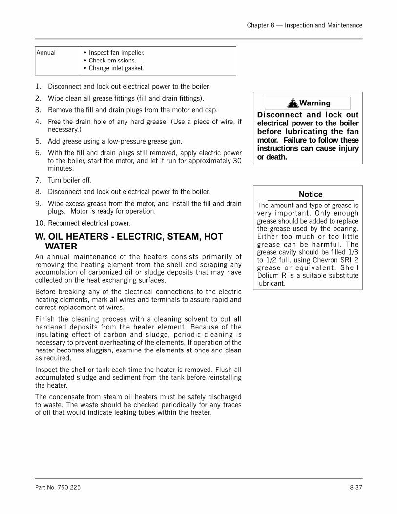
Chapter 8 — Inspection and Maintenance
1. Disconnect and lock out electrical power to the boiler.
2. Wipe clean all grease fittings (fill and drain fittings).
3. Remove the fill and drain plugs from the motor end cap.
4. Free the drain hole of any hard grease. (Use a piece of wire, ifnecessary.)
5. Add grease using a low-pressure grease gun.
6. With the fill and drain plugs still removed, apply electric powerto the boiler, start the motor, and let it run for approximately 30minutes.
7. Turn boiler off.
8. Disconnect and lock out electrical power to the boiler.
9. Wipe excess grease from the motor, and install the fill and drainplugs. Motor is ready for operation.
10. Reconnect electrical power.
W. OIL HEATERS - ELECTRIC, STEAM, HOT WATER
An annual maintenance of the heaters consists primarily ofremoving the heating element from the shell and scraping anyaccumulation of carbonized oil or sludge deposits that may havecollected on the heat exchanging surfaces.
Before breaking any of the electrical connections to the electricheating elements, mark all wires and terminals to assure rapid andcorrect replacement of wires.
Finish the cleaning process with a cleaning solvent to cut allhardened deposits from the heater element. Because of theinsulating effect of carbon and sludge, periodic cleaning isnecessary to prevent overheating of the elements. If operation of theheater becomes sluggish, examine the elements at once and cleanas required.
Inspect the shell or tank each time the heater is removed. Flush allaccumulated sludge and sediment from the tank before reinstallingthe heater.
The condensate from steam oil heaters must be safely dischargedto waste. The waste should be checked periodically for any tracesof oil that would indicate leaking tubes within the heater.
Annual • Inspect fan impeller. • Check emissions.• Change inlet gasket.
! Warning
Disconnect and lock outelectrical power to the boilerbefore lubricating the fanmotor. Failure to follow theseinstructions can cause injuryor death.
Notice
The amount and type of grease isvery important. Only enoughgrease should be added to replacethe grease used by the bearing.Either too much or too littlegrease can be harmful. Thegrease cavity should be filled 1/3to 1/2 full, using Chevron SRI 2grease or equiva lent . Shel lDolium R is a suitable substitutelubricant.
Part No. 750-225 8-37

Chapter 8 — Inspection and Maintenance
The hot water oil heater (Figure 8-29) contains a heat transfersolution. Oil flows through an inner tube while boiler watersurrounds the outer tube. The space between the two tubes is filledwith the heat transfer solution and is connected to an expansionchamber on the rear of the heater. A visual indicator on the chamberreveals the presence of any oil if an oil leak occurs.
A 50/50 solution of permanent antifreeze and water is generallyused as the heat transfer solution. If there is no danger of freezing,plain water may be used as a replenishment if necessary to refill.
Evidence of oil in either the steam heater condensate or in the waterheater indicator demands prompt repairs.
Table 8-4 Typical Windbox Temperature for Natural Gas
X. COMBUSTIONThe frequency of burner adjustments depends upon several factor,including; type of burner, type of fuel, load conditions, ambienttemperature, climatic variables, and general maintenance practices.
The air-fuel ratio should be checked monthly in order to alert theoperator to losses in efficiency, which do not produce visible flamechange. Any time maintenance is performed on the burner linkage,the air-fuel ratio should be checked. Readjustment of the burnermay be required due to variations in fuel composition. A combustionanalyzer should be used to adjust air-fuel ratio for maximumoperating efficiency. If your burner requires adjustments, contactyour local Cleaver-Brooks authorized representative for assistance.
Figure 8-29 Circuit Layout of Hot Water Oil Heater
60 PPM 130°-140° F
30 PPM 160°-175° F
25 PPM 185°-195° F
20 PPM 195°-210° F
8-38 Part No. 750-225

Chapter 8 — Inspection and Maintenance
Notes
Table 8-5 Recommended Boiler Inspection Schedule
DAILY MONTHLY SEMI-ANNUALLY ANNUALY
• Check water level
• Check combustion visually
• Blow down boiler
• Blow down watercolumn
• Record feedwater pressure/temperature
• Record flue gastemperature
• Record oil pressure and temperature
• Record gas pressure
• Treat water according to the established program
• Record atomizing air pres-sure
• Inspect burner
• Inspect for flue gas leak
• Inspect for hot spots
• Check cams
• Check for tight closing of fuel valve
• Check fuel and air linkage
• Check indicating lights and alarms
• Check operating and limitcontrols
• Check safety and interlockcontrols
• Check for leaks, noise, vibra-tion, unusual conditions, etc.
• Check low water cutoff oper-ation
• Clean low water cutoff
• Clean oil pump strainer, fil-ter
• Clean air cleaner and air/oil separator
• Inspect refractory
• Remove and clean oil pre-heater
• Check air pump coupling alignment
• Inspect / repair burner hous-ing to refractory seal
• Clean fireside surfaces
• Clean breeching
• Inspect waterside sur-faces
• Check operation of safety valves
8-39 Part No. 750-94
Chapter 8 — Inspection and Maintenance
8-40 Part No. 750-94
Notes
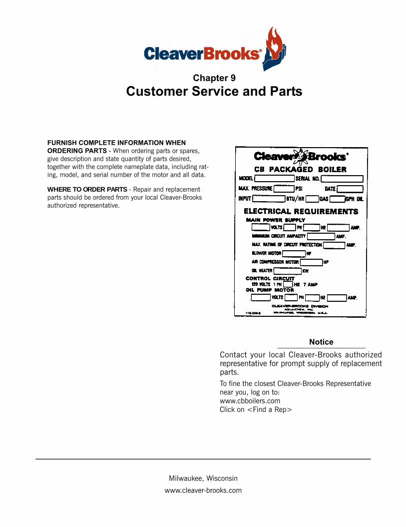
Chapter 9
Customer Service and Parts
Notice
Contact your local Cleaver-Brooks authorizedrepresentative for prompt supply of replacementparts.To fine the closest Cleaver-Brooks Representative near you, log on to:www.cbboilers.comClick on <Find a Rep>
FURNISH COMPLETE INFORMATION WHEN
ORDERING PARTS - When ordering parts or spares, give description and state quantity of parts desired, together with the complete nameplate data, including rat-ing, model, and serial number of the motor and all data.
WHERE TO ORDER PARTS - Repair and replacement parts should be ordered from your local Cleaver-Brooks authorized representative.
Milwaukee, Wisconsin
www.cleaver-brooks.com
Chapter 9 — Customer Service and Parts
9-2 Part No. 750-225
Table Of Contents
AIR COMPRESSOR AND PIPING . . . . . . . . . . . . . . . . . . . . . . . . . . . 9-3AIR COMP. PIPING 50HZ - BELT DRIVE CB . . . . . . . . . . . . . . . . . . . . 9-4AIR LINE PIPING . . . . . . . . . . . . . . . . . . . . . . . . . . . . . . . . . . . . . . 9-5ALSTROM HEATER H/O HW CB,CB-LE . . . . . . . . . . . . . . . . . . . . . . . 9-6ALSTROM HEATER H/O HW CB,CB-LE . . . . . . . . . . . . . . . . . . . . . . . 9-7CONTROL PANEL - CB,CB-LE . . . . . . . . . . . . . . . . . . . . . . . . . . . . . . 9-8CONTROL PANEL - CB,CB-LE . . . . . . . . . . . . . . . . . . . . . . . . . . . . . 9-9ENTRANCE BOX CB,CB-LE . . . . . . . . . . . . . . . . . . . . . . . . . . . . . . 9-10ENTRANCE BOX - CB,CB-LE,CBW,CBH . . . . . . . . . . . . . . . . . . . . . . 9-11FRONT HEAD LINKAGE . . . . . . . . . . . . . . . . . . . . . . . . . . . . . . . . . 9-12FRONT HEAD (ELECTRICAL) . . . . . . . . . . . . . . . . . . . . . . . . . . . . . 9-13FRONT HEAD (ELECTRICAL) . . . . . . . . . . . . . . . . . . . . . . . . . . . . . 9-14GAS TRAIN EQUIPMENT - CB,CB-LE . . . . . . . . . . . . . . . . . . . . . . . 9-15GAS TRAIN EQUIPMENT CB,CB--LE . . . . . . . . . . . . . . . . . . . . . . . 9-16HEAVY OIL PIPING STEAM CB,CB-LE . . . . . . . . . . . . . . . . . . . . . . . 9-17HEAVY OIL PIPING STEAM CB,CB-LE,CBW . . . . . . . . . . . . . . . . . . . 9-18STANDARD IMPELLER, IMPELLER HOUSING & AIR INTAKE . . . . . . . 9-19PRESSURE CONTROLS . . . . . . . . . . . . . . . . . . . . . . . . . . . . . . . . . 9-20LIGHT OIL PIPING . . . . . . . . . . . . . . . . . . . . . . . . . . . . . . . . . . . . 9-21OIL/AIR PIPING-FRONT HEAD (LIGHT OIL) . . . . . . . . . . . . . . . . . . 9-22OIL/AIR PIPING-FRONT HEAD (LIGHT OIL) . . . . . . . . . . . . . . . . . . . 9-23TEMPERATURE CONTROLS . . . . . . . . . . . . . . . . . . . . . . . . . . . . . . 9-24W.C.-MAIN & AUX. CB . . . . . . . . . . . . . . . . . . . . . . . . . . . . . . . . . . 9-25W.C.-MAIN & AUX. CB . . . . . . . . . . . . . . . . . . . . . . . . . . . . . . . . . . 9-26
Notes
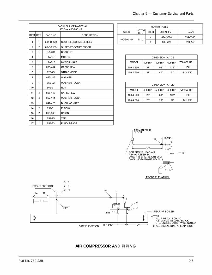
Chapter 9 — Customer Service and Parts
Part No. 750-225 9-3
3-3/4"
3-3/4"
505-D-120
NOTES:
FRONT ELEVATION
30"
85-B-2183
8-A-815
847-426
859-81
928-45
868-404
952-92
952-145
868-143
869-21
952-11412 WASHER - LOCK
10 NUT
11 CAPSCREW
8 WASHER
9 WASHER - LOCK
6 CAPSCREW
7 STRAP - PIPE
14 ELBOW
13 BUSHING - RED
16-13/16" "A"
REAR OF BOILER3/16"
2
1
SIDE ELEVATION
FRONT SUPPORT
6
8
10
7
9
13
1211
MODEL
150"
113-1/2"
119"
91"
92"
40"
37"
37"
100 & 200
400 & 600
DIMENSION "A" CB
700-800 HP600 HP500 HP400 HP
BASIC BILL OF MATERIAL
BRACKET13
SUPPORT COMPRESSOR22
COMPRESSOR ASSEMBLY11
DESCRIPTIONPART NO.QTYITEM
96" DIA. 400-800 HP
1
2
1
1
1
1
4
4
1
AIR MANIFOLDBLOCK
3
4
4 1 TABLE MOTOR
5 1 TABLE MOTOR HALF
5
MOTOR TABLE
H.P.MOTOR
ITEM 200-460 V 575 VUSED
1. ALL PIPE 3/4" SCH. 40ASTM A120 WELDED BLACK
FOR FRONT HEAD AIRPIPING REFER TO DWG. 146-C-107 (LIGHT OIL)
STL. UNLESS OTHERWISE NOTED.
2. ALL DIMENSIONS ARE APPROX.
1/8"
11"
DWG. 146-D-126 (HEAVY OIL)
2
1
UNION15
TEE859-25
859-339
16
17 858-83 PLUG, BRASS1
1415
15
14
400-800 HP 7-1/24
5
894-3384
819-227 819-227
894-3386
400 HP 500 HP 600 HP 700-800 HP
DIMENSION "A" LE
400 & 600
100 & 200
25"
25"
28"
80"
79"
107"
101-1/2"
138"
MODEL
AIR COMPRESSOR AND PIPING

Chapter 9 — Customer Service and Parts
9-4 Part No. 750-225
FRONT ELEVATION
94
12
11
13
FRONT SUPPORT
9
REAR
SIDE ELEVATION
14
7 10 16
6
869-364 NUT HEX
858-965 UNION ELBOW
847-431 BUSHING
928-45
868-404 CAPSCREW
STRAP, PIPE
BILL OF MATERIAL
1
ITEM QTY PART No. DESCRIPTION
COMPRESSOR ASSEMBLY
BRACKET, COMPRESSOR MTG. (SEE DET. IT. 2)2
BRACKET, COMPRESSOR MTG. (SEE DET. IT. 3)3
BRACKET4
LOCKWASHER952-114
WASHER952-133
CAPSCREW 4 868-144
1
1
8-A-815
8-2730
8-2727
505-D-121
NUT HEX.869-21
WASHER"952-145
LOCKWASHER 952-92
8
7
6
5
12
11
10
9
15
14
13
8
23
1
AIR MANIFOLDBLOCK
1
1
4
4
2
1
1
1
1
1
1
16
MOTOR 200/380 VOLT (IF REQUIRED)SEE TABLE1
5
1-3/8"7-1/2 HP220/380 VOLT
MOTOR TABLE
RATING BOREUSED ON
400-800 HP
17 1 SEE TABLE SHEAVE
3 PHASE
ITEM 5
894-3390
ITEM 17
921-506
17
15
AIR COMP. PIPING 50HZ - BELT DRIVE CB
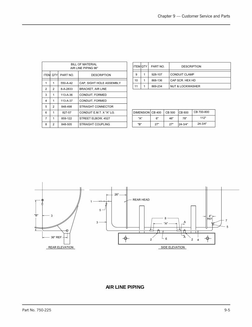
Chapter 9 — Customer Service and Parts
Part No. 750-225 9-5
SIDE ELEVATION
26"
REAR HEAD
3
3
2
"B"
36" REF.
"A"
1
A
A
4
4"REF.
2
8-A-2833
113-A-36
113-A-374 1 CONDUIT, FORMED
BILL OF MATERIAL
CONDUIT, FORMED13
BRACKET, AIR LINE22
CAP, SIGHT HOLE ASSEMBLY11
DESCRIPTIONPART NO.QTYITEM
AIR LINE PIPING 96"
550-A-42
CB 400 CB 500 CB 600 CB 700-800DIMENSION
6" 46" 78" 112""A"
"B" 24-3/4"24-3/4"27"27"
REAR ELEVATION
848-4985 STRAIGHT CONNECTOR
6 CONDUIT E.M.T. X "A" LG.
7 STREET ELBOW, 4527
STRAIGHT COUPLING8 848-505
859-122
827-57
928-107
ITEM QTY PART NO. DESCRIPTION
9 CONDUIT CLAMP
10 CAP SCR. HEX HD
11 NUT & LOCKWASHER869-234
868-136
5
8
6
7
5
2
1
1
2
1
1
1
AIR LINE PIPING
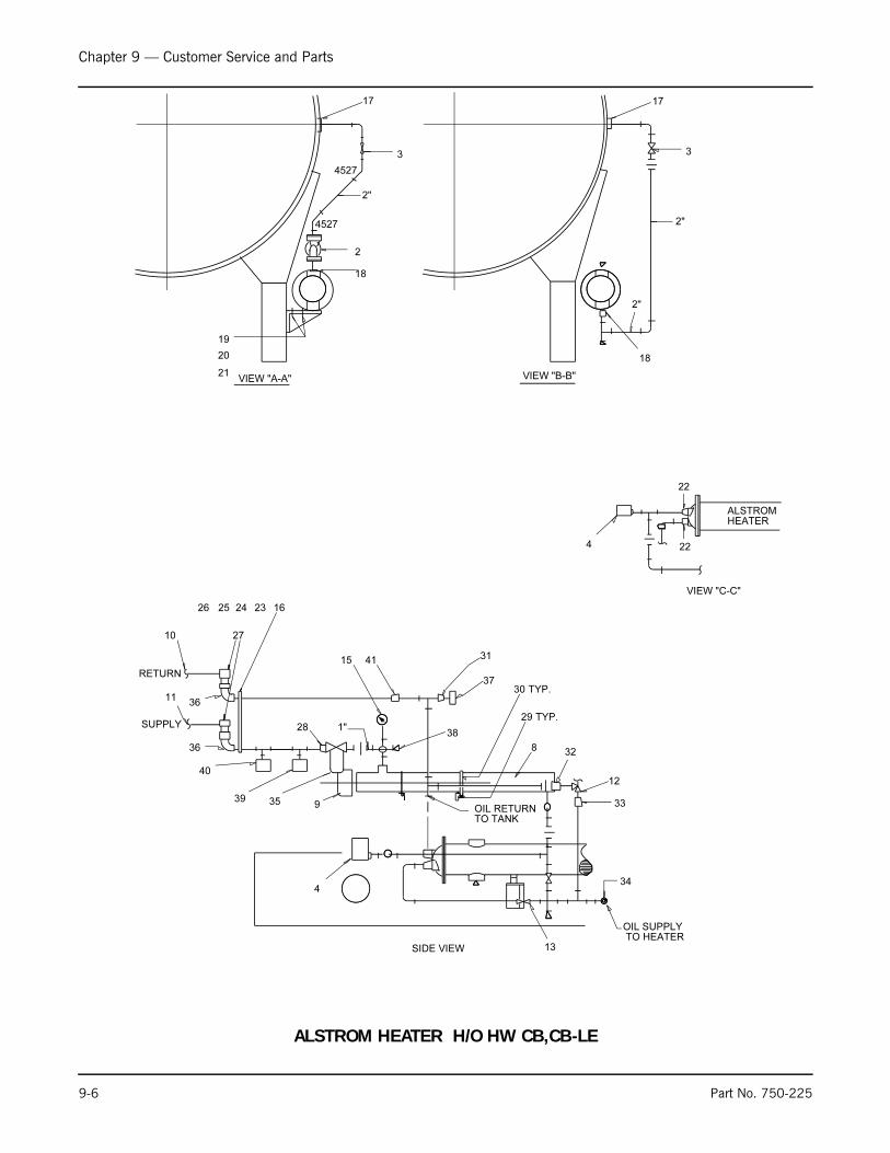
Chapter 9 — Customer Service and Parts
9-6 Part No. 750-225
34
33
32
TYP.
TYP.30
29
27
26 25 24 23
22
22
21
20
19
4527
4527
18
17 17
18
16
1"
TO HEATEROIL SUPPLY
OIL RETURNTO TANK
12
SUPPLY
RETURN
8
10
ALSTROMHEATER
4
VIEW "C-C"
2"
2"
VIEW "A-A" VIEW "B-B"
2
3 3
2"
35 9
3611
36
38
13
4
15
37
28
39
40
41 31
SIDE VIEW
ALSTROM HEATER H/O HW CB,CB-LE
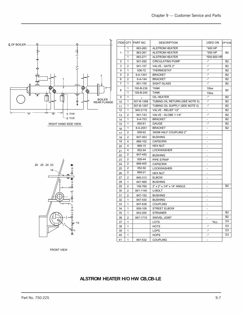
Chapter 9 — Customer Service and Parts
Part No. 750-225 9-7
-STREET ELBOW 859-10934
31
32
33
847-430
847-638 COUPLING
BUSHING
-
-
-
-
-
-
-
-
-CAPSCRW
LOCKWASHER
HEX NUT
ELBOW
BUSHING
2" x 2" x 1/4" x 14" ANGLE
26
149-769
847-468
845-313
869-21
952-92
868-405
29
28
27
25
24
30 841-1140 U-BOLT -
-
-
-
-
-
-3000# HALF COUPLING 2"
BUSHING
CAPSCRW
HEX NUT
LOCKWASHER
BUSHING
19
847-442
952-94
869-15
868-102
847-453
858-62
22
21
20
18
17
23 928-44 PIPE STRAP -
26 25 24 23
REAR FLANGEBOILER
-BRACKET8-A-255116
13
14
OF BOILERLC
TYP.
TYP.6
5
RIGHT HAND SIDE VIEW
"A" "B"
17
BRACKET
ALSTROM HEATER
OIL HEATER
ALSTROM HEATER
10
11
13
14
15
*400 HP
-*
-*
-*
-*
-*
-*
*500 HP
507-B-1268
507-B-1267
940-2116
941-143
8-A-753
850-61
*
195-B-239
8-A-144
8-A-1301
836-72
941-157
901-292
863-271
863-261
863-260
851-155 SIGHT GLASS
12
7
ITEM QTY PART NO. DESCRIPTION
ALSTROM HEATER
1
2 CIRCULATING PUMP
3 VALVE - GATE 2"
4 THERMOSTAT
5 BRACKET
6
TANK
GAUGE
BRACKET
VALVE - GLOBE 1-1/4"
VALVE - RELIEF 1/2"
TUBING OIL SUPPLY (SEE NOTE 5)
TUBING OIL RETURN (SEE NOTE 5)
10kw
-*
-*
-
-*
-
-*
USED ON
1
1
1
1
2
1
2
2
1
1
1
1
1
1
2
1
1
1
1 15kwTANK195-B-2408
2
2
4
4
4
2
2
2
2
2
2
1
2
2
1
1
1
2
1 -STRAINER843-25535
36 847-1715 SWIVEL JOINT -
*ALLLOTS37 1
-*9
2 847-152 BUSHING
-COUPLING847-53241
40 HOPS1
1
1
1 HOTS38
39 LOPS
OPTION
B2
B2
B2
B2
B2
B2
B2
B2
B2
B2
B2
B2
B2
B2
B2
B2
B2
-*
-*
-*
B2
B2
D3
D3
D3
D3
FRONT VIEW
*600-800 HP
ALSTROM HEATER H/O HW CB,CB-LE
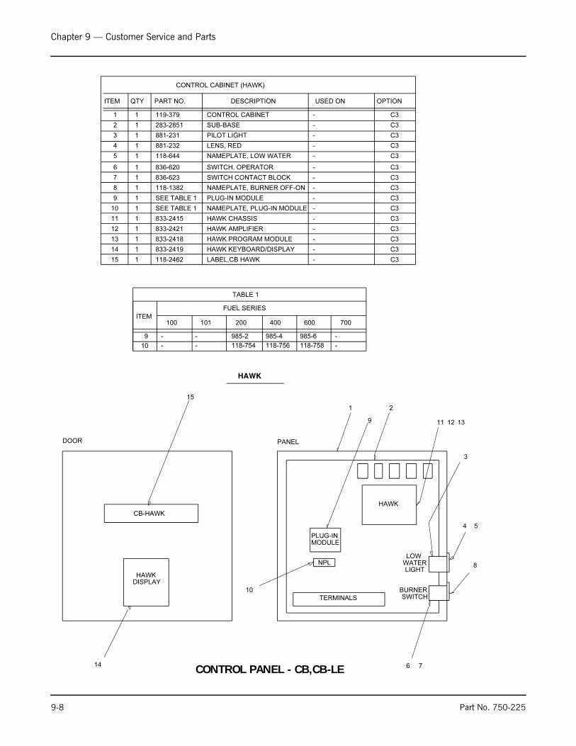
Chapter 9 — Customer Service and Parts
9-8 Part No. 750-225
HAWK AMPLIFIER
HAWK CHASSIS
NAMEPLATE, PLUG-IN MODULE
PLUG-IN MODULE
NAMEPLATE, BURNER OFF-ON
SWITCH CONTACT BLOCK
SWITCH, OPERATOR
NAMEPLATE, LOW WATER
LENS, RED
PILOT LIGHT
SUB-BASE
CONTROL CABINET1 1 119-379 -
2 1 283-2851 -
-881-23113
-881-23214
-118-64415
-836-62016
-836-62317
-118-138218
-SEE TABLE 119
-SEE TABLE 1110
-833-2415111
12 1 833-2421 -
13
CONTROL CABINET (HAWK)
ITEM QTY DESCRIPTION USED ONPART NO.
-833-2419114
-833-24181 HAWK PROGRAM MODULE
HAWK KEYBOARD/DISPLAY
700
-
-
600
118-758
985-6
400
118-756
985-4
200
118-754
985-2
101
-
--
-
100ITEM
9
FUEL SERIES
HAWK
DOOR PANEL
14
1 2
9 11
10
3
4
8
6
12 13
5
7
TABLE 1
HAWKDISPLAY
NPL
PLUG-INMODULE
LOWWATERLIGHT
BURNERSWITCH
HAWK
TERMINALS
LABEL,CB HAWK15 1 118-2462 -
OPTION
C3
CB-HAWK
15
C3
C3
C3
C3
C3
C3
C3
C3
C3
C3
C3
C3
C3
C3
10
CONTROL PANEL - CB,CB-LE

Chapter 9 — Customer Service and Parts
Part No. 750-225 9-9
NUT, SELF-LOCKING
SCREW, SELF-TAPPING
SCREW, SELF-TAPPING
BASE
RELAY
NAMEPLATE FOR MODULE "B"
PLUG-IN MODULE "B"
NAMEPLATE FOR MODULE "A"
PLUG-IN MODULE "A"
STARTER (SEE NOTE 2)
PROGRAMMER-FLAME DETEC
PROGRAMMER-FLAME DETEC
PROGRAMMER-MODULE
PROGRAMMER-AMPLIFIER
PROGRAMMER-AMPLIFIER
PROGRAMMER-CHASSIS
SWITCH LEDGE
SWITCH LEDGE
SWITCH LEDGE
SWITCH LEDGE
SUB-BASE
SUB-BASE
CONTROL CABINET (LESS LEDGE)
PART NO. USED ONDESCRIPTIONQTYITEM
1 1 119-313 -
2
1 283-D-2880 CB70 FUEL 100,101,200,700
CB70 FUEL 400,600283-D-28051
STANDARD283-1701
3ANNUNCIATOR283-26091
HIGH STACK TEMP. CONT.283-29651
HIGH STACK TEMP. CONT.283-29661
4
CB100833-25821
CB70833-22041
5 E100833-23841
61 833-2383 E100
71 817-1742 CB70
1 817-1933 E100
8 1 -
9 1 -
10 1 -
11 1 SEE TABLE 2 -
12 1 -
13 1 -
14 1 -
15 2 841-1483 WITH ITEM 14
16 3 841-801 WITH ITEM 8
17 4 841-89 -
CONTROL CABINET (NON-HAWK)
TABLE 2
-
9
ITEM100
13
12
11
10
-
-
-
-
- -
-
-
-
-
101
-
-
-
985-2
118-754
833-2261
200
833-2263
985-8
118-760
985-4
118-756
833-2261
400
833-2263
985-8
118-760
985-6
118-758
-
600
-
-
-
-
-
-
700
-
3
5
7-1/2
10
15
200-208VBM HP
2
TABLE 1 - ITEM 8
220-240V 346-416V 440-480V 575-600V
20
30
40
50
NOTE 160
NOTE 1
NOTE 1
NOTE 1
833-1197
833-1197
833-1886
833-1885
833-1885
833-1884
833-1884
NOTE 1
NOTE 1
NOTE 1
833-1197
833-1197
833-1886
833-1886
833-1885
833-1885
833-1884
833-1884
NOTE 1
833-1197
833-1197
833-1197
833-1886
833-1886
833-1885
833-1885
833-1884
833-1884
833-1884
NOTE 1
833-1197
833-1197
833-1197
833-1886
833-1886
833-1885
833-1885
833-1884
833-1884
833-1884
NOTE 1
833-1197
833-1197
833-1197
833-1886
833-1886
833-1885
833-1885
833-1884
833-1884
833-1884
NOTES: 1. STARTER IS IN OWN ENCL. MOUNTED ON THE FR0NT HEAD.
2. OVERLOADS ARE TO BE SUPPLIED BASED ON MOTOR NAMEPLATE
AMP. RATING.
1
9
16
3
10
11
12
13,2
4,
17
NON-HAWK
14,15
5,6,
7
8, STARTERMODULE "A"
MODULE "B"
NPL
PROGRAMMER
TERMINALS
NPL
FLAMEFAILURE
LOADDEMAND
BURNERSWITCH
FLAMECONTROL
MANUAL-AUTO
FUELVALVE
LOWWATER
MANUALR W W R
& ANNUNCIATOR
VOLTAGE
FUEL SERIES
PLUG-IN
PLUG-IN
SEE TABLE 1
3. FOR NON-HAWK PANEL, MAXIMUM QUANTITY OF RELAYS, TIMERS,OR COMBINATION OF BOTH IS 8. FOR HAWK PANEL THE MAXIMUMQUANTITY IS 5.
1 283-D-2881 SUB-BASE CB100 FUEL 100,101,200,700
1 833-2292 CB70PROGRAMMER-CHASSIS
1 833-2382 PROGRAMMER-CHASSIS E100
1 833-2584 PROGRAMMER-AMPLIFIER CB100
1 833-2583 PROGRAMMER-MODULE CB100
1 817-2261 PROGRAMMER-FLAME DETEC CB100
E100 FUEL 400,600SUB-BASE1 283-D-2804
1 283-2882 E100 FUEL 100,101,200,700
CB100 FUEL 400,600283-28721 SUB-BASE (283-D-2804)
SUB-BASE (283-D-2881)
OPTION
D3
D4
D4
D0
D0
D5
D5
C4
C5
C6
C7
D4
D5
D0
D3
D3
D3
D3
D3
D3
D3
D0
D5
D4
D0
D0
D5
D5
D4
-
-
-
14
SEE NOTE 3
CONTROL PANEL - CB,CB-LE

Chapter 9 — Customer Service and Parts
9-10 Part No. 750-225
400
350
300250
225
200
175
150
125110
100
80
70
6050
45
40
35
30
2520
17.5
15
12
109
8
7
6.25
5.6
54.5
4.25
4
3.5
3.22.8
2.5
2.25
2
1.8
1.41
.8
RATINGAMP
832-1036
832-1035
832-1034832-621
832-1025
832-490
832-478
832-489832-488
832-476
832-477
832-140
832-574832-487
832-139
832-653
832-138
832-627
832-461832-298
832-137
832-347
832-481
832-136832-486
832-636
832-402
832-135
832-421
832-485832-299
832-152
832-662
832-484
832-483832-460
832-482
832-279
832-480
832-1211
BUSSMAN FRN
832-1041832-444
832-1033
832-1040
832-1104
832-1026
832-1002832-443
832-847
832-502
832-501
832-1115832-500
832-622
832-499
832-149
832-626
832-148832-147
832-448
832-146
832-471
832-145832-366
832-332
832-144
832-498
832-472
832-143832-442
832-441
832-433
832-142832-416
832-495
832-494
832-497
832-493
832-492832-141
832-491
BUSSMAN FRS
832-1037
832-1038
832-1039
450
500
600
-
833-1360833-970
833-929
833-1029833-1023
833-2178*
833-1884
833-1886
833-2098
-
STARTERSIZE
00
01
2
34
5
SQ-DOPEN TYPE
833-1197
833-1885
833-2570
NEMA 1 ENCL NEMA 1 ENCL
-
833-1363
833-1544
OPEN TYPEA-B
-
833-1298
833-1447
833-1362
-
833-1623833-1626
833-1838
833-1904833-1979
-
THREE-PHASE, 120 VAC CONTROL COIL
STARTER PART NO.S
* FULL VOLTAGE 200 V COIL
250
125
70
30
AMPS
832-964
832-782
832-781
832-780
PART NO.
BLOCK PART NO.S
SECONDARY FUSE
550-600
440-480
346-416
220-240
200-208110-120
15 KW HEATER
10 KW HEATER7-1/2 KW HEATER
5 KW HEATER
3 KW HEATER
2 KW HEATER
200 HP MOTOR150 HP MOTOR
125 HP MOTOR
100 HP MOTOR
75 HP MOTOR
60 HP MOTOR50 HP MOTOR
40 HP MOTOR
30 HP MOTOR
25 HP MOTOR
20 HP MOTOR
15 HP MOTOR10 HP MOTOR
7-1/2 HP MOTOR
5 HP MOTOR
3 HP MOTOR
2 HP MOTOR1-1/2 HP MOTOR
1 HP MOTOR
3/4 HP MOTOR
1/2 HP MOTOR
1/3 HP MOTOR
1/4 HP MOTOR
FRN-5-6/10
FRS-2
FRS-2-1/2
FRS-2-8/10
FRN-3-1/2
FRN-4FRN-7
FRN-50
FRN-30
FRN-20
FRN-40
FRN-30FRN-25
FRN-20
FRN-17-1/2
FRN-12
FRN-9
FRN-8
FRN-12
FRS-3-1/2
FRS-3-1/2
FRS-4
FRN-7
FRN-8FRN-15
FRN-25
FRN-15
FRN-12
FRN-60
FRN-50
FRN-35
FRN-20
FRN-15FRN-12
FRN-10
FRN-9
FRN-6-1/4
FRN-4-1/2
FRN-4-1/2
FRN-15
FRS-4-1/2
FRS-5-6/10
FRS-6-1/4
FRN-10
FRN-12FRN-17-1/2
FRN-45
FRN-30FRN-25
FRN-15
FRN-10
FRN-7
FRN-450
FRN-350
FRN-250
FRN-200FRN-175
FRN-150
FRN-100
FRN-90
FRN-70
FRN-60FRN-40
FRN-30
FRN-20
FRN-12
FRN-9FRN-7
FRN-5
FRN-4-1/2
FRN-2-8/10
FRN-1-8/10
FRN-1-8/10
FRN-20
FRS-5-6/10
FRS-7
FRS-8
FRN-12
FRN-15FRN-25
FRN-45
FRN-30FRN-25
FRN-15
FRN-10
FRN-7
FRN-600
FRN-4-1/2
FRN-2-8/10
FRN-1-8/10
FRN-1-8/10
FRS-35
FRS-25FRS-15
FRS-10
FRS-6-1/4
FRS-150
FRS-125FRS-100
FRS-80
FRS-60
FRS-50
FRS-40
FRS-30FRS-20
FRS-17-1/2
FRS-12
FRS-8
FRS-5-6/10FRS-4
FRS-3-2/10
FRS-2-1/4
FRS-1-8/10
FRS-25
FRS-17-1/2FRS-12
FRS-8
FRS-5-6/10
FRS-4-1/2
FRS-300FRS-225
FRS-200
FRS-150
FRS-125
FRS-100FRS-80
FRS-70
FRS-50
FRS-40
FRS-35
FRS-25FRS-17-1/2
FRS-15
FRS-10
FRS-6-1/4
FRS-4-1/2FRS-3-2/10
FRS-2-1/4
FRS-1-8/10
FRS-1-4/10
FRS-1
FRS-1
FRS-20
FRS-12FRS-10
FRS-6-1/4
FRS-4-1/2
FRS-3-2/10
FRS-250FRS-200
FRS-150
FRS-125
FRS-100
FRS-80FRS-70
FRS-50
FRS-40
FRS-35
FRS-25
FRS-20FRS-15
FRS-12
FRS-8
FRS-5
FRS-3-1/2FRS-2-1/2
FRS-1-8/10
FRS-1-4/10
FRS-1
FRS-8/10
FRS-8/10
ELECTRICAL LOAD110-120 V
SINGLE PHASE 50/60 HERTZ
220-240 V 200-208 V 220-240 V
THREE PHASE 50/60 HERTZ
346-416 V 440-480 V 550-660 V
RECOMMENDED MAXIMUM "FUSETRON" FUSE SIZES
FRN-500 FRN-450
FRN-5
FRN-7FRN-9
FRN-12
FRN-20
FRN-30
FRN-35FRN-50
FRN-70
FRN-80
FRN-100
FRN-150
FRN-175FRN-200
FRN-250
FRN-300
FRN-400
1/2 KVA. 1 KVA. 1-1/2 KVA. 2 KVA.CONTROL CIRCUIT
XFMR VOLTAGE
CONSULT CLEAVER-BROOKS ELECTRICAL ENGINEERING DEPT. FOR "FUSETRON" FUSE SIZE
FOR POWER SYSTEMS WITH VOLTAGE, FREQUENCY OR PHASE NOT MENTIONED ABOVE.
MOTOR, OIL HEATER, & CCT FUSE SIZING
5
32
1-1/2
1
3/41/2
1/3
1/41/6
POWERHORSE-
56
3424
20
16
13.89.8
7.2
5.84.4
AMPS
1
1
0
00
00
0000
STARTER
115
30.8
18.713.2
11
8.8
7.65.4
4
3.22.4
AMPS
2
10
0
0
0000
00
0000
STARTER
200
28
1712
10
8
6.94.9
3.6
2.92.2
AMPS
2
10
0
00
0000
00
0000
STARTER
230
VOLTAGE-SINGLE PHASE
MOTOR AMP DRAWS & STARTER SIZINGAMP DRAWS BASED ON NEC TABLE 430-148.
AMP DRAWS BASED ON NEC TABLE 430-150.MOTOR AMP DRAWS & STARTER SIZING
VOLTAGE-THREE PHASE
380
STARTER
00
0000
00
00
00
1
12
AMPS
1.2
1.72.1
3.1
4.1
5.89.2
13.3
25.4
230
STARTER
00
0000
00
0
01
1
22
AMPS
2
33.5
5
7
9.515
22
2842
200
STARTER
00
0000
00
0
01
1
AMPS
2.5
3.54.0
5.5
7.5
1117
24
3146
HORSE-
POWER
1/2
3/41
1-1/2
2
35
7-1/2
1015 21
14
11
7.55
3.5
2.5
21.5
1
AMPS
21
1
00
00
00
0000
00
STARTER
460
1711
9
64
3
2
1.51
1
AMPS
21
1
00
00
00
0000
00
STARTER
600
2
2
33
3
22
27
3241
52
2
2
33
3
27
34
4052
6550
4030
25
20
143
11488
75
59
4
3
3
130
10480
68
54
4
43
3
3
78.6
62.948.4
41.1
32.6
3
33
2
2
32
4
5
5 493.2515416960 77 4 62 4
16.9
107-1/2
5
3
RATING
KW
27.820.8
13.9
8.3
200
VOLTAGE-THREE PHASE
25.118.8
12.6
7.5
230
15.211.4
7.6
4.6
380
12.69.4
6.3
3.8
460
107.5
5
3
600
OIL HEATER AMP DRAWS
CONTROL CIRCUIT TRANSFORMER AMP DRAWS
575
0.9
1.7
2.6
3.5
460
1.3
2.1
3.3
4.3
380
1.1
2.6
3.9
5.3
230
2.2
4.3
6.5
8.7
VOLTAGE-THREE PHASE
208
2.4
5
7.5
10
KVA
1/2
1
1-1/2
2
WHEN SIZING TOTAL BOILER AMP DRAW USE 125%OF THE LARGEST LOAD.
MAIN POWER TERMINAL
FUSE PART NO.S
2
3
832-496
ENTRANCE BOX CB,CB-LE

Chapter 9 — Customer Service and Parts
Part No. 750-225 9-11
18
17
16
15
14
13
12
11
10
9
8
7
6
5
4
3
2
1
ITEM
1
1
*
3
1
1
*
3
*
3
1
1
1
1
1
1
1
1
1
1
QTY PART NO.
434-61
118-1865
884-78
848-223
118-297
832-347
848-338
848-375
SEE TABLE
SEE TABLE
SEE TABLE
SEE TABLE
SEE TABLE
SEE TABLE
118-1667
SEE TABLE
SEE TABLE
833-2197
118-299 OIL HEATER EMBLEM
OIL HEATER CONTACTOR
OIL HEATER FUSE BLOCK
OIL HEATER FUSE
AIR COMPRESSOR EMBLEM
AIR COMPRESSOR MOTOR STARTER
AIR COMPRESSOR MOTOR FUSE BLOCK
AIR COMPRESSOR MOTOR FUSE
BLOWER MOTOR FUSE BLOCK
BLOWER MOTOR FUSE
MAIN POWER TERMINAL BLOCK
ENT. BOX (24 X 24 X 6) (NEMA 1)
ENT. BOX (24 X 18 X 6) (NEMA 1)
ENT. BOX (18 X 15 X 6) (NEMA 1)
FUSE, FRN-15
NAMEPLATE, DECAL CONTROL CIRCUIT
FUSE BLOCK, CONTROL CIRCUIT
GROUND LUG
PLATE, I.D. FOR TERM. STRIP
TERMINAL STRIP, 25 TERMS
DESCRIPTION USED ON
-
FUEL 700
FUEL 100, 101, & 200
FUEL 400 & 600 & "LE"
DETERMINED BY TOTAL AMP LOAD
-
-
-
-
-
W/ ITEMS 11, 12, & 13
-
-
W/ ITEMS 15 & 16
W/ ITEMS 15, 16, & 17
848-1083
BILL OF MATERIAL FOR ENT. BOX
QTY 1 ON VOLTAGE 240,=
QTY 3 OTHERWISE* <
8 3 2
10
12 16
17
6
5
18
1 11 15
4
9
7
96"BRACKET, 36" X 30" BOX8-B-3163
8-B-3164
8-B-3165
8-B-31871
1
1
1
19
19
BRACKET, 30" X 30" BOX
BRACKET, 24" X 24" BOX
BRACKET, 18" X 24" BOX
96"
96"
96"
14
13
22
FRONT FLANGE
SIDE VIEW
C OF 96" BOILERL
FRONT VIEW
19
7
20
ENTRANCE
CABINET
1 8-3186 BRACKET, E-BOX 78"
20
FOR 96" BOILERS
96"BRACKET, E-BOX8-31141 BOILERS, LE
BOILERS
BOILERS, NON-LE1 8-3190 BRACKET, E-BOX 96"
OPTION
BLOWER MOTORS CALLED FOR ON FRONT HEAD (ELECTRICAL)
AIR COMPRESSOR MOTORS CALLED FOR ON AIR COMPRESSOR ASSY
OIL HEATERS AND OIL PUMPS CALLED FOR ON OIL PIPING ASSY
NOTE:
C8
C8
C8
C8
C8
C8
C8
C8
C8
C8
C8
C8
C8
C8
C8
C8
C8
C8
C8
C8
ENTRANCE BOX - CB,CB-LE,CBW,CBH
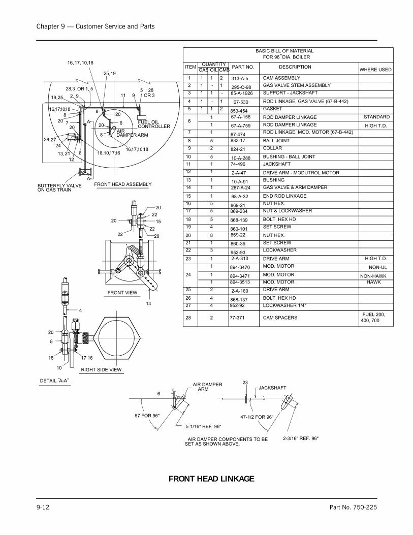
Chapter 9 — Customer Service and Parts
9-12 Part No. 750-225
5-1/16" REF. 96"
6
AIR DAMPER COMPONENTS TO BESET AS SHOWN ABOVE.
RIGHT SIDE VIEW
14
20
22
15
22
22
20
20
4
20
8
18 17
10
FRONT VIEW
DETAIL A-A
57 FOR 96" 47-1/2 FOR 96"
23JACKSHAFT
AIR DAMPERARM
2-3/16" REF. 96"
16
" "
BUTTERFLY VALVEON GAS TRAIN
6
8
20
8
17,10,18,
207
8
20
17,10,
2
18
19,25 9
17, 18 10,
25, 19
11 39 1
CONTROLLERFUEL OIL
20
3 5
A
A
8
OR
AIRDAMPER ARM
12
13,21
24
51,OR
2726,
2828,
16
16,
16,
FRONT HEAD ASSEMBLY
16, 10,1817,
19 SET SCREW
BOLT, HEX HD
NUT & LOCKWASHER869-234
868-139
860-101
GAS VALVE & ARM DAMPER287-A-24
END ROD LINKAGE68-A-32
NUT HEX. 869-21
10-A-288 BUSHING - BALL JOINT
824-21 COLLAR
883-17 BALL JOINT
10-A-91
2-A-47
74-496 JACKSHAFT
DRIVE ARM - MODUTROL MOTOR
BUSHING
BASIC BILL OF MATERIAL
FOR 96 DIA. BOILER
1
ITEMQUANTITY
PART NO. DESCRIPTION
CAM ASSEMBLY
GAS VALVE STEM ASSEMBLY2
SUPPORT - JACKSHAFT3
ROD LINKAGE, GAS VALVE (67-B-442)4
GASKET853-454
ROD DAMPER LINKAGE 67-A-156
ROD LINKAGE, MOD. MOTOR (67-B-442)67-474
2
1
-
1 67-530
85-A-1926
295-C-98
313-A-5
GAS OIL CMB
-
1
-
1
1
1
1
1
5
2
5
1
5
5
1
1
5
4
1
1
1
1
8
7
6
5
12
11
10
9
16
15
14
13
18
17
20
21
3
1
8
952-93
860-39
869-22 NUT HEX.
SET SCREW
LOCKWASHER 22
1 67-A-759 ROD DAMPER LINKAGE
24
23
1
1
1
1
894-3470 MOD. MOTOR
2-A-310 DRIVE ARM
894-3513
894-3471 MOD. MOTOR
MOD. MOTOR
WHERE USED
STANDARD
HIGH T.D.
HAWK
NON-HAWK
NON-UL
HIGH T.D.
25 2 2-A-160 DRIVE ARM
1 1 2
BOLT, HEX HD 868-137426
LOCKWASHER 1/4"952-92427
28 2 77-371 CAM SPACERSFUEL 200,
400, 700
"
FRONT HEAD LINKAGE
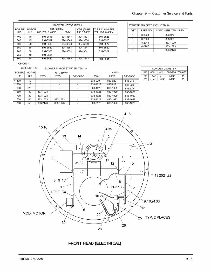
Chapter 9 — Customer Service and Parts
Part No. 750-225 9-13
1615
11
3231
1098
30
7
1/2" FLEX
6MOD. MOTOR
13 14 1
34
2
35
4 5
3
19,20,21,22
1712 11
12
18
23
9,10, 3324,
12
25
2710
TYP. 2 PLACES
26
29
28
"A" 1-1/4" 2"
750-800 600-700 H.P.
CONDUIT DIAMETER
700
650
600
500
400
BOILER
894-3520
200, 230, & 460V 600V
894-3520
894-3518
894-3517
894-3516
894-3551
894-3551
894-3549
894-3548
894-3547
BLOWER MOTOR ITEM 1
-
894-3553
894-3521
894-3522
750
800
H.P. H.P.MOTOR
50
40
10
15
20
30
30
ODP (60 HZ) ODP (50 HZ)
894-3543
-
894-3537
894-3538
894-3539
894-3541
230 & 380V
894-3541 894-3529
200, 230, & 460V
894-3529
894-3527
894-3526
894-3525
-
894-3531
T.E.F.C. & HI-EFF.
833-1029
833-970
833-929
833-929
833-1029
833-1029
HAWK
380-600V
NON-HAWK
30
30
20
15
10
40
50
MOTOR
H.P.H.P.
800
750
833-2178
833-1023
833-1023
833-1023
BLOWER MOTOR STARTER ITEM 15
833-1023
833-1023
BOILER
400
500
600
650
700
230V200V 200V
833-1023
833-1023
833-1029
833-1029
833-929
833-1029
833-1029
833-1029
833-929
833-929
833-1023
833-1023
833-1023
833-2178
-
-
-
-
--
-
-
833-1029
8-2938
8-2939
8-2943
8-2707
833-970
833-929
833-1029
833-1023
STARTER BRACKET ASSY. ITEM 16
PART NO.QTY
1
1
1
1
USED WITH ITEM 15 P/N.
1 - 833-2178
2" 1-1/4" "B"
230V
-
-
-
-
-
380-600V
-
-
(SEE NOTE #4)
383736
*
*
* CB ONLY.
500 400
3/4”
1-1/4”1”
1-1/4”
FRONT HEAD (ELECTRICAL)
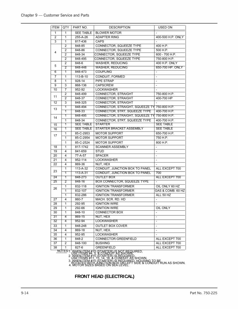
Chapter 9 — Customer Service and Parts
9-14 Part No. 750-225
NOTES:
2. WHEN ITEM #15 (STARTER) IS REQUIRED,USE ITEMS #11, 13, 14, 16, & CONDUIT AS SHOWN.
32 4 952-94 -
-869-15431
-848-10130
OIL ONLY292-66129
-292-951
-860-7427
GAS & COMB. 60 HZ832-1071
OIL ONLY 60 HZ832-118126
-848-16225
ALL EXCEPT 700848-273124
ALL EXCEPT 700113-A-32123
-869-36422
-952-114421
-77-A-57420
-841-659419
-817-1742118
800 H.P.85-C-25241
650-700 H.P. 85-C-2953117
SEE TABLE116
SEE TABLESEE TABLE115
848-341
848-495114
400-700 H.P. 848-331
750-800 H.P. 848-494113
-848-325312
400-700 HP 848-372
750-800 H.P. 848-499211
-952-92710
-868-13639
8 1 928-14 -
7 1 113-B-10 -
6 1 848-473 -
2 848-448 650-700 HP. ONLY5
2 848-6 400 H.P. ONLY
848-34 600 - 700 H.P.4
2 848-86 500 H.P.
848-85 400 H.P.
3 1 817-436 -
400-500 H.P. ONLY255-A-2612
-SEE TABLE11
ITEM QTY DESCRIPTION USED ONPART NO.
BLOWER MOTOR
ADAPTER RING
CAPS
CONNECTOR, SQUEEZE TYPE
WASHER, REDUCING
WASHER, REDUCING
COUPLING
CONDUIT, FORMED
PIPE STRAP
CAPSCREW
LOCKWASHER
CONNECTOR, STRAIGHT
CONNECTOR, STRAIGHT
CONNECTOR, STRAIGHT
CONNECTOR, STRAIGHT, SQUEEZE TY
CONNECTOR, STRT, SQUEEZE TYPE
STARTER
MOTOR SUPPORT
MOTOR SUPPORT
SCANNER ASSEMBLY
STUD
SPACER
LOCKWASHER
NUT, HEX
CONDUIT, JUNCTION BOX TO PANEL
OUTLET BOX
BOX CONNECTOR, SQUEEZE TYPE
IGNITION TRANSFORMER
IGNITION TRANSFORMER
MACH. SCR. RD. HD
IGNITION WIRE
IGNITION WIRE
CONNECTOR BOX
NUT, HEX
CONNECTOR, SQUEEZE TYPE
CONNECTOR, SQUEEZE TYPE
2
2
CONNECTOR, STRT, SQUEEZE TYPE
CONNECTOR, STRAIGHT, SQUEEZE TY 750-800 H.P.
400-700 H.P.
STARTER BRACKET ASSEMBLY SEE TABLE
OUTLET BOX COVER -848-248133
NUT, HEX. -869-18434
LOCKWASHER -952-95435
LOCKWASHER
1. WHEN ITEM #15 (STARTER) IS NOT REQUIRED,USE ITEMS #4, 5, & CONDUIT AS SHOWN.
ROTATED WITH JUNCTION BOX ON LEFT SIDE & CONDUIT RUN AS SHOWN.3. WHEN ITEM #15 (STARTER) IS REQUIRED, HOUSING TO BE
4. MOTOR SIZES BASED ON SEA LEVEL.
2 CONNECTOR, SQUEEZE TYPE 750-800 H.P.848-495
38 1 827-6 ALL EXCEPT 700GREENFIELD
37 2 848-100 ALL EXCEPT 700BUSHING
36 1 848-2 ALL EXCEPT 700CONNECTOR-GREENFIELD
CONDUIT, JUNCTION BOX TO PANEL1 113-A-31 700
IGNITION TRANSFORMER1 832-286 ALL 50 HZ
28
1 85-C-2954 MOTOR SUPPORT 750 H.P.
FRONT HEAD (ELECTRICAL)

Chapter 9 — Customer Service and Parts
Part No. 750-225 9-15
OVERALL LENGTH
A
A
SEE TABLE 1
37 3839 40
TYP
4 PLACES
TYPTYP
3"
M2
34
88
TYPTYP6
TYP 7
1553
45
14
11
42
31
9
9
1 12 2
4231
M5
11
M4
10"M3
M110"10"
MAIN GAS TRAIN
M6
9
3 3
4 4
11
4 PLACESTYP
40393837
A
A
GAS TRAIN EQUIPMENT - CB,CB-LE
2 8-1002 BRACKET 2", 2-1/2", 3" GTS
12 4" GTS BRACKET8-10023
1 940-165 BUTERFLY VALVE 4" 4" GTS 1 940-134 BUTERFLY VALVE 3" 150-800 HP 1 940-133 BUTERFLY VALVE 2-1/2" 100-125,125A HP
1 845-194 ELBOW 125-800 HP 22 1 845-313 ELBOW 50-125A HP 21 SCHEM. 825-30 PILOT GAS COCKS - 20 1 850-109 PILOT GAUGE - 1 507-1299 PILOT TUBING 400-800 HP 1 507-1015 PILOT TUBING 250-350 HP 1 507-1348 PILOT TUBING 125-200 HP 19 1 507-593 PILOT TUBING 50-125A HP 18 1 918-356 PILOT REGULATOR -
17 TABLE 1 948-2 PILOT VENT VALVE -
16 TABLE 1 948-197 PILOT VALVE - 1 858-171 UNION 3" GTS 1 858-170 UNION 2-1/2" GTS 15 1 858-169 UNION 2" GTS 1 919-99 CAPLUG 3" GTS 1 919-105 CAPLUG 2-1/2" GTS 14 1 919-104 CAPLUG 2" GTS
157-631 S.O. NIPPLE 4" GTS, 2" VVS 157-470 S.O. NIPPLE 4" GTS, 3/4" VVS 157-1041 S.O. NIPPLE 3" GTS, 1-1/4" VVS 157-1040 S.O. NIPPLE 3" GTS, 3/4" VVS 157-1042 S.O. NIPPLE 2-1/2" GTS, 1-1/4" VVS 11 TABLE 1 157-1043 S.O. NIPPLE 2" GTS, 1" VVS 10 NOT USED NOT USED 948-55 MAIN VENT VALVE 2" VVS 948-54 MAIN VENT VALVE 1-1/4" VVS 948-53 MAIN VENT VALVE 1" VVS 9 TABLE 1 948-2 MAIN VENT VALVE 3/4" VVS - (NOTE 4) S.O. NIPPLE ALL HP (HAWK) 2 157-469 S.O. NIPPLE 1/2" 4" GTS (STD) 2 157-1039 S.O. NIPPLE 1/2" 3" GTS (STD) 2 157-1723 S.O. NIPPLE 1/4" 2-1/2" GTS (STD) 8 2 157-1722 S.O. NIPPLE 1/4" 2" GTS (STD) - (NOTE 4) HIGH GAS PRESS. SWITCH ALL HP (HAWK) 1 817-752 HIGH GAS PRESS. SWITCH 300-800 HP (STD) 7 1 817-1935 HIGH GAS PRESS. SWITCH 50-250 HP (STD) 1 507-6786 GAS PRESS. SENSOR 600-800 HP (HAWK) 1 507-6785 GAS PRESS. SENSOR 200-500 HP (HAWK) 1 507-6784 GAS PRESS. SENSOR 50-175 HP (HAWK) 1 817-751 LOW GAS PRESS. SWITCH 300, 350, 500-800 HP (STD) 1 817-789 LOW GAS PRESS. SWITCH 400 HP (STD) 6 1 817-774 LOW GAS PRESS. SWITCH 50-250 HP (STD) 2 941-131 LUBRICATED PLUG VALVE 4" GTS 2 941-130 LUBRICATED PLUG VALVE 3" GTS 2 941-129 LUBRICATED PLUG VALVE 2-1/2" GTS 5 2 941-1947 LUBRICATED PLUG VALVE 2" GTS 945-151 ACTUATOR (POC) 4" GTS 4 945-143 ACTUATOR (POC) 2",2-1/2",3" GTS 940-4451 VALVE (POC) 4" GTS
940-4546 VALVE (POC) 3" GTS 250-800 HP 940-4545 VALVE (POC) 2-1/2" GTS 3 940-4544 VALVE (POC) 2" GTS 945-149 ACTUATOR (STD) 4" GTS
2 945-139 ACTUATOR (STD) 2",2-1/2",3" GTS 50-350 HP 940-4409 VALVE (STD) 4" GTS
940-4541 VALVE (STD) 3" GTS 250-350 HP
940-4540 VALVE (STD) 2-1/2" GTS 1 TABLE 1 940-4539 VALVE (STD) 2" GTS
ITEM QTY P/N DESCRIPTION USED ON
949-385 VALVE STD W/ ACTUATOR 3" GTS 400-800 HP*
*
949-384 VALVE POC W/ ACTUATOR 3" GTS 400-800 HP*
* NOTE: ITEM #2 IS NOT REQUIRED FOR 3" GAS TRAINS 400-800 HP.THE ACTUATORS ARE INCLUDED W/ ITEMS #1 & 3 GAS VALVES.
3 8-1159 BRACKET MAXON 4" GTS MAXON 2", 2-1/2", 3" GTS BRACKET8-11592
OPTION
B3
B3
B3
B3
B3
B3
C3
B3
B3
B3
B3
B3
B3B3B3
B3
B3B3
B3
13 NOT USED NOT USED
23
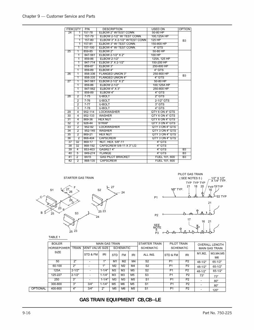
Chapter 9 — Customer Service and Parts
9-16 Part No. 750-225
4" GTS
4" GTS
4" GTS
4" GTS
FLANGE
GASKET 4"
CAPSCREW 5/8-11 X 3" LG
NUT, HEX. 5/8"-11
849-274
853-403
868-192
869-17
5
4
32
3237
38
39
40
E
D
F
120"-
80"-
80"-
73"73"
65-1/2"48-1/2"
65-1/2"48-1/2"
65-1/2"48-1/2"
M3,M4,M5M1,M2,
MAIN GAS TRAIN
OVERALL LENGTH
TABLE 1
400-800 4" 3/4" 2" M5 M6 M5 S1 P1 P2
300-800 3" 3/4" 1-1/4" M5 M6 M5 S1 P1 P2
250 3" - 1-1/4" M3 M3 M5 S1 P1 P2
125-227 2-1/2" - 1-1/4" M3 M3 M5 S3 P1 P2
125A 2-1/2" - 1-1/4" M3 M3 M5 S2 P1 P2
60-100 2" - 1" M2 M2 M4 S2 P1 P2
50 2" - 1" M1 M2 M4 S2 P1 P2
SIZE
HORSEPOWER TRAIN VENT VALVE SIZE SCHEMATIC SCHEMATIC SCHEMATIC
BOILER MAIN GAS TRAIN STARTER TRAIN PILOT TRAIN
ITEM QTY P/N DESCRIPTION USED ON
36 2 868-404 CAPSCREW QTY 3 ON 4" GTS
35 2 869-21 HEX NUT QTY 3 ON 4" GTS
34 2 952-145 WASHER QTY 3 ON 4" GTS
33 2 952-92 LOCKWASHER QTY 3 ON 4" GTS
32 2 928-44 STRAP QTY 3 ON 4" GTS
31 4 869-36 HEX NUT QTY 6 ON 4" GTS
30 4 952-133 WASHER QTY 6 ON 4" GTS
29 4 952-114 LOCKWASHER QTY 6 ON 4" GTS
3 7-78 U-BOLT 4" GTS
2 7-77 U-BOLT 3" GTS
2 7-76 U-BOLT 2-1/2" GTS
28 2 7-75 U-BOLT 2" GTS
1 859-89 ELBOW 4" 4" GTS
1 847-562 ELBOW 4" X 3" 250-800 HP
1 859-86 ELBOW 2-1/2" 100,125A HP
27 1 847-561 ELBOW 2-1/2" X 2" 50-80 HP
1 858-335 FLANGED UNION 4" 4" GTS
26 1 858-336 FLANGED UNION 3" 250-800 HP
1 859-89 ELBOW 4" 4" GTS
1 859-87 ELBOW 3" 250-800 HP
1 847-714 ELBOW 3" X 2-1/2" 150-200 HP
1 859-86 ELBOW 2-1/2" 125A, 125 HP
1 847-561 ELBOW 2-1/2" X 2" 100 HP
25 1 859-85 ELBOW 2" 50-80 HP
1 157-100 ELBOW 4" W/ TEST CONN. 4" GTS
1 157-81 ELBOW 3" W/ TEST CONN. 150-800 HP
1 157-80 ELBOW 3" X 2-1/2" W/TEST CONN 125 HP
1 157-79 ELBOW 2-1/2" W/ TEST CONN. 100,125A HP
24 1 157-78 ELBOW 2" W/TEST CONN. 50-80 HP
27
25
25
2726
25
1/2" TYP.
TYP22
24
24
23
1716
TYP19
16
TYP
201821
23
24
S2
S3
TYP TYP
C
A
B
23
S1
STARTER GAS TRAIN
PILOT GAS TRAIN
P1
P2
P3
42
41 2
2
8A15
868-135
GAS PILOT BRACKET
CAPSCREW
FUEL 101, 600
FUEL 101, 600
( SEE NOTES 5 ) 1/2" X 1/2"
M6
X 1/4" TYP.
TYP
21
21
OPTIONAL
SEENOTE
6
OPTION
B3
B3
B3
B3
B3
STD & FM IRI STD FM IRI STD & FM IRIALL INS.
GAS TRAIN EQUIPMENT CB,CB--LE

Chapter 9 — Customer Service and Parts
Part No. 750-225 9-17
6
23
22
4
3
21
5
43
17
14 15
18
39
14 19 15
20 21
42
16-300 PSI
0-15 PSI
3/4"
OIL SUPPLY TO HEATER
HEATEROUTLET
1-1/4" x 3/4" x 1-1/4"
3/4"
TO TANKOIL RETURN
14-1/4"
3/4"
WELD TO LEG
SUPPLY
RETURN
A
A
HINGEWELD TO
29"
5-1/2"
12"=CB 30-3/4"
X
DETAIL "D"
3/4"
SECTION "C-C"
SECTION "A-A"
7
SECTION "B-B"
TIGHTEN NUTS ONLY ENOUGHSO THAT CONTACT IS MADEBETWEEN ELEMENT FLANGE AND
10
9
11
11
10
3/4" x 1/2" x 3/4"
3/4"
24
25
FLAT GASKET.
1-1/4"
CONTINUED AT SECTION "C-C"
37
35 36
38
37363534
1-1/4"
26 32
4140
17
1/2"x1/2"x1/4"
4139 40
27
33
36
31
29
8
28
303/4" x 1/2"
1/2"
1/2"
34
3/4"
12
12
13
B
B
CC
1/4" TYP.
4445
3/4" X 3/4" X 1/4"
46
SEENOTE 4
26 SEE NOTE 7
1" X 3/4" X 3/4"
SEENOTE 2
12
6
6
12
43 SEE NOTE 4
1" X 3/4"" X 3/4"1"
1"
MIN.
6
LC OF HINGE PIN
1/2"=CBLE
8-1/2"
8-1/2"
SIDE VIEWSTEAM PIPING TO HEATER SHALL BE -
0 - 15 PSI, 3/4" SCH. 4016 - 200 PSI, 1/2" SCH. 40201 -300 PSI, 1/2" SCH. 80
HEAVY OIL PIPING STEAM CB,CB-LE

Chapter 9 — Customer Service and Parts
9-18 Part No. 750-225
USED ON
16
7"
1"
16-300#
201-300#
16-200#
0-15#
201-300#
16-200#
0-15#
16-300#
0-15#
-
-
GLOBE VALVE 1/2"1
REGULATOR, STEAM 1/2"1
REGULATOR, STEAM 1/2"1
REGULATOR, STEAM 1/2"1
STEAM GAUGE1
1 VALVE 3/4"
1 VALVE 1/2"
1 CHECK VALVE 3/4"
1 CHECK VALVE 1/2"
1 CHECK VALVE 1/2"
1 GLOBE VALVE 3/4"
1 GLOBE VALVE 1/2"
STRAINER
CAPACITOR2
THERMOSTAT (OHT & SHT)2
18
RELIEF VALVE17
BARCO JOINTS26
BRACKET15
BRACKET14
OIL HEATER13
BRACKETS22
HEATER TANK11
DESCRIPTIONPART NO.QTYITEM
9
10
11
12
13
14
15
16
17
18
1 OIL PRESSURE GAUGE
1 BRACKET -
19
8-A-661
850-61
652-B-24
8-A-650
8-A-2551
8-A-753
847-1715
940-2296
843-255
836-A-320
832-311
941-40
941-142
940-458
940-135
940-142
948-273
948-227
850-3
817-260
817-330
918-12
941-605
16-150#
151-250#
251-300#
-
-
-
-
-
-
-
-
-
STEAM PIPING TO HEATER SHALL BE -
NOTES:1. UNLESS OTHERWISE NOTED, ALL OIL PIPE TO BE
SCH. 40 ASTM A120 WELDED BLACK STL. AND ALL
2. SWIVEL JOINTS SHOULD BE LINED UP EVENWITH FLANGE RING.
3. ALL DIMENSIONS ARE APPROX.
REAR VIEW
16 - 300#
-
-
-
-
-
-
-
-
-
869-234
858-311
952-94
868-136
869-21
952-145
928-44
868-405
841-1458
952-92
841-1142
847-466
853-692
32-A-2394
507-B-1267
507-B-1268
934-256
940-142
847-426
928-45 -PIPE CLAMP 3/4"
BUSHING, 1" x 3/4"
41
39
36
32
31
30
29
28
20 CHECK VALVE 3/4"
21 STEAM TRAP 3/4"
22 TUBING OIL RETURN
23 TUBING OIL SUPPLY
24 GASKET
25 GASKET, 0-RING
26 BUSHING 3/4" X 1/2"
27
LOCKWASHER 1/4"
STUD
U-BOLT
STRAP 1/2"
FLATWASHER 1/4"
HEX NUT 1/4-20
CAPSCRW. HEX HD. 1/4-20 x 3/4"
LOCKWASHER 1/2"
FULL COUPLING 1/4" NPT
NUT LOCKWASHER COMB. 1/4"
-
-
-
-
-
-
-
-
-
-40
33
37
35
34
38
-
CAPSCRW. HEX HD. 1/4-20 x 7/8"
REDUCING COUPLING 1" x 3/4"
REDUCING COUPLING 1-1/4" x 3/4"
847-533
847-641
2
1
3
3
4
1
2
*3
1
1
1
1
1
1
1
8
1
8
1
11
1
2
HOTS
ALL* LOTS
0 - 15 PSI, 3/4" SCH. 4016 - 200 PSI, 1/2" SCH. 40201 -300 PSI, 1/2" SCH. 80
42
2 845-313 ELBOW 1/2" ODC X 1/2" NPT -
FITTINGS TO BE 150# M.I..
MAT'L.: ASME SA106
43
1 854-11 SIPHON
46
45
44
1
HOPS
BUSHING, 1" X 1/2" -
LOPS
847-468
4. FOR IRI OR F & I INSURANCE SUPPLY ITEM 43.FOR KEMPER SUPPLY ITEMS 43 & 26.
(SEE NOTE 5)
(SEE NOTE 5)
5. FOR HAWK DO NOT USE ITEM #23,USE QTY 2 OF ITEM # 22.
GR. B SMLS.
16 - 300#
6. ITEMS 42, 43, 44, & 45 ARE USED FOR NON-HAWKONLY. FOR HAWK USE SOLID STATE SENSOR
7. FOR IRI, F & I, OR FM SUPPLY ITEM 42.FOR NO INSURANCE,OR KEMPER SUPPLY ITEMS 42 & 26.
B2
OPTION
B2
B2
B2
B2
B2
B2
B2
B2
B2
B2
D3
D3
B2
B2
B2
B2
B2
B2
D3
B2
B2
B2
B2
B2
B2
D3
B2
*
*
*
*
1
1
1
1
12
6
12
6
FRONT VIEW
LC OF HINGE PIN
38
3635
37
4
HEAVY OIL PIPING STEAM CB,CB-LE,CBW
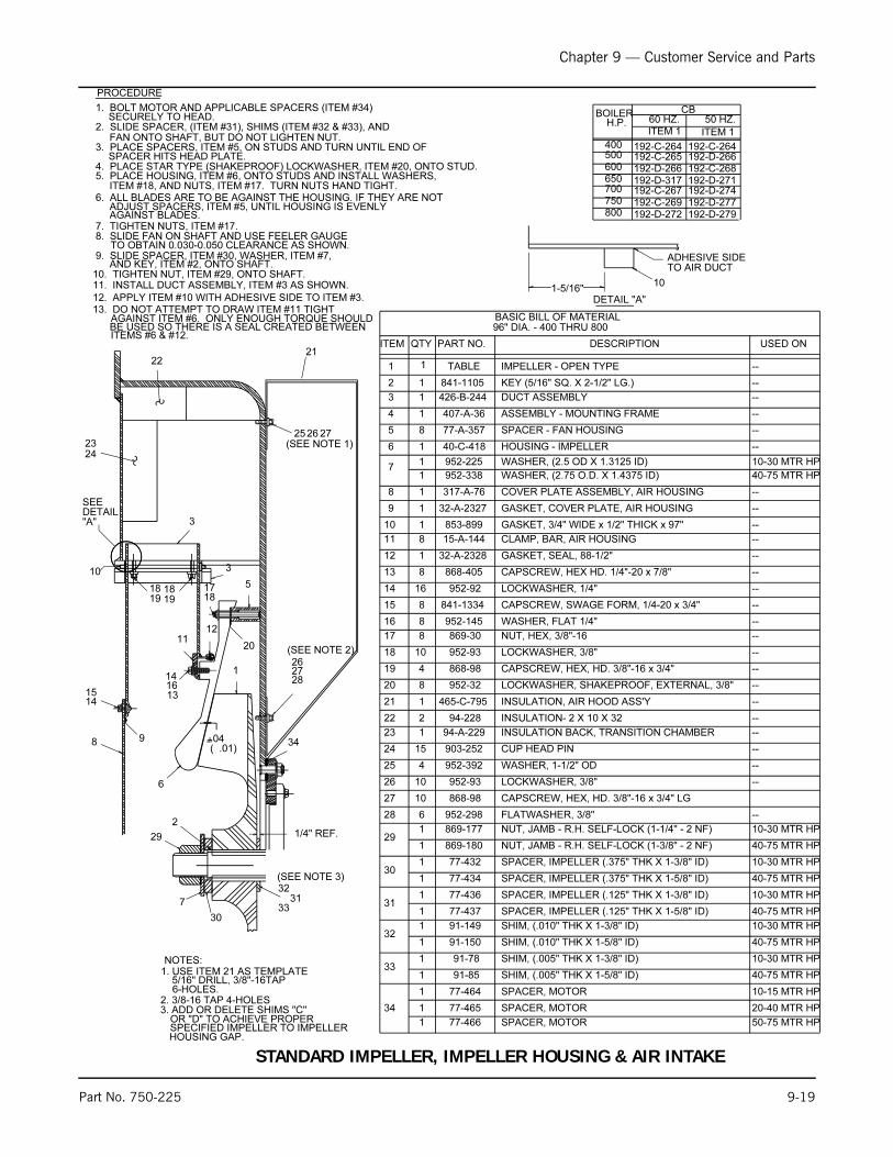
Chapter 9 — Customer Service and Parts
Part No. 750-225 9-19
BASIC BILL OF MATERIAL
13
2
IMPELLER - OPEN TYPE1
DESCRIPTIONPART NO.QTYITEM
96" DIA. - 400 THRU 800
426-B-244
KEY (5/16" SQ. X 2-1/2" LG.)
DUCT ASSEMBLY
SPACER - FAN HOUSING
ASSEMBLY - MOUNTING FRAME
77-A-357
407-A-364 1
5 8
9
8
6
7
1
1 317-A-76
32-A-2327
COVER PLATE ASSEMBLY, AIR HOUSING
GASKET, COVER PLATE, AIR HOUSING
WASHER, (2.75 O.D. X 1.4375 ID)
HOUSING - IMPELLER
952-338
40-C-4181
1
13
12
10
11
868-405 CAPSCREW, HEX HD. 1/4"-20 x 7/8"
17
16
14
15
1 32-A-2328
869-30
GASKET, SEAL, 88-1/2"
NUT, HEX, 3/8"-16
CLAMP, BAR, AIR HOUSING
GASKET, 3/4" WIDE x 1/2" THICK x 97"
15-A-144
853-8991
8
952-93 LOCKWASHER, 3/8"
LOCKWASHER, SHAKEPROOF, EXTERNAL, 3/8"
CAPSCREW, HEX, HD. 3/8"-16 x 3/4"
952-32
868-98
18
19
20
3
1819 19
18
10
1415
8 9
11
141613
12
1
5
20
17
21/4" REF.
.04 -
+
1-5/16"10
ADHESIVE SIDETO AIR DUCT
SEE
DETAIL "A"
952-92
841-1334
952-145
LOCKWASHER, 1/4"
CAPSCREW, SWAGE FORM, 1/4-20 x 3/4"
WASHER, FLAT 1/4"
1
1 841-1105
TABLE
4
10
8
8
16
8
8
8
PROCEDURE
800750700650600500400
192-D-272192-C-269192-C-267192-D-317192-D-266192-C-265192-C-264
192-D-279192-D-277192-D-274192-D-271192-C-268192-D-266192-C-264
ITEM 1ITEM 150 HZ.60 HZ.
CBBOILERH.P.
NOTES:1. USE ITEM 21 AS TEMPLATE
5/16" DRILL, 3/8"-16TAP6-HOLES.
2. 3/8-16 TAP 4-HOLES
1
4
15
2
1
6
10
10
CUP HEAD PIN
INSULATION BACK, TRANSITION CHAMBER
INSULATION- 2 X 10 X 32
903-252
94-A-229
94-228
28
27
26
868-98
952-298
CAPSCREW, HEX, HD. 3/8"-16 x 3/4" LG
FLATWASHER, 3/8"
LOCKWASHER, 3/8"952-93
WASHER, 1-1/2" OD952-392
23
22
24
25
INSULATION, AIR HOOD ASS'Y465-C-79521
2526 27(SEE NOTE 1)
282726
(SEE NOTE 2)
2122
23
1. BOLT MOTOR AND APPLICABLE SPACERS (ITEM #34)SECURELY TO HEAD.
2. SLIDE SPACER, (ITEM #31), SHIMS (ITEM #32 & #33), ANDFAN ONTO SHAFT, BUT DO NOT LIGHTEN NUT.
3. PLACE SPACERS, ITEM #5, ON STUDS AND TURN UNTIL END OFSPACER HITS HEAD PLATE.
4. PLACE STAR TYPE (SHAKEPROOF) LOCKWASHER, ITEM #20, ONTO STUD.5. PLACE HOUSING, ITEM #6, ONTO STUDS AND INSTALL WASHERS,
ITEM #18, AND NUTS, ITEM #17. TURN NUTS HAND TIGHT.6. ALL BLADES ARE TO BE AGAINST THE HOUSING. IF THEY ARE NOT
ADJUST SPACERS, ITEM #5, UNTIL HOUSING IS EVENLY AGAINST BLADES.
7. TIGHTEN NUTS, ITEM #17.8. SLIDE FAN ON SHAFT AND USE FEELER GAUGE
TO OBTAIN 0.030-0.050 CLEARANCE AS SHOWN.9. SLIDE SPACER, ITEM #30, WASHER, ITEM #7,
AND KEY, ITEM #2, ONTO SHAFT.10. TIGHTEN NUT, ITEM #29, ONTO SHAFT.11. INSTALL DUCT ASSEMBLY, ITEM #3 AS SHOWN.
12. APPLY ITEM #10 WITH ADHESIVE SIDE TO ITEM #3.13. DO NOT ATTEMPT TO DRAW ITEM #11 TIGHT
AGAINST ITEM #6. ONLY ENOUGH TORQUE SHOULDBE USED SO THERE IS A SEAL CREATED BETWEENITEMS #6 & #12.
USED ON
--
--
--
--
--
--
--
--
--
--
--
--
--
--
--
--
--
--
--
--
--
--
--
--
--
--
40-75 MTR HP
40-75 MTR HP
10-30 MTR HP
10-30 MTR HP
40-75 MTR HP
10-30 MTR HP
40-75 MTR HP
10-30 MTR HP
10-15 MTR HP
40-75 MTR HP
10-30 MTR HP
20-40 MTR HP
40-75 MTR HP91-150 SHIM, (.010" THK X 1-5/8" ID)
77-465 SPACER, MOTOR
91-78
91-85
77-464
SHIM, (.005" THK X 1-3/8" ID)
SHIM, (.005" THK X 1-5/8" ID)1
1
1
1
1
1
1
1
1
1
1
1
SPACER, IMPELLER (.375" THK X 1-3/8" ID)
NUT, JAMB - R.H. SELF-LOCK (1-3/8" - 2 NF)
NUT, JAMB - R.H. SELF-LOCK (1-1/4" - 2 NF)
77-432
869-180
869-177
77-437
91-149
SPACER, IMPELLER (.125" THK X 1-5/8" ID)
SHIM, (.010" THK X 1-3/8" ID)
SPACER, IMPELLER (.125" THK X 1-3/8" ID)77-436
SPACER, IMPELLER (.375" THK X 1-5/8" ID)77-434
29
SPACER, MOTOR
30
10-30 MTR HP1 952-225 WASHER, (2.5 OD X 1.3125 ID)
31
32
33
34
1 SPACER, MOTOR77-466 50-75 MTR HP
3. ADD OR DELETE SHIMS "C"OR "D" TO ACHIEVE PROPERSPECIFIED IMPELLER TO IMPELLERHOUSING GAP.
29
7
30
3231
(SEE NOTE 3)
34
33
18
3
24
( .01)
DETAIL "A"
6
STANDARD IMPELLER, IMPELLER HOUSING & AIR INTAKE
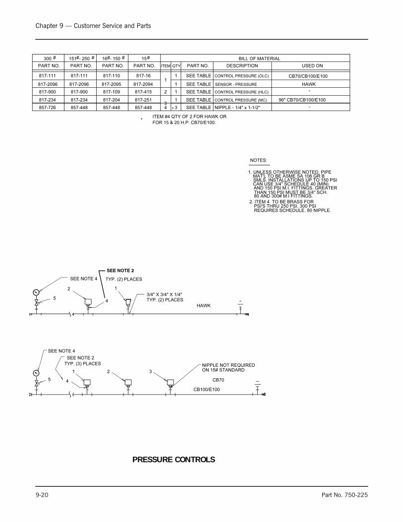
Chapter 9 — Customer Service and Parts
9-20 Part No. 750-225
TYP. (3) PLACES
1
4
2 3
CONTROL PRESSURE (MC)
CONTROL PRESSURE (HLC)
SEE TABLE
SEE TABLE
817-16817-110817-111
4
817-111
PART NO.
300
PART NO.
151 - 250
PART NO.
16 - 150 15
PART NO.
SEE TABLE
ITEM QTY PART NO. DESCRIPTION
11 CONTROL PRESSURE (OLC)
2
31
BILL OF MATERIAL
NOTES:
SMLS. INSTALLATIONS UP TO 150 PSICAN USE 3/4" SCHEDULE 40 (MIN) AND 150 PSI M.I. FITTINGS. GREATER THAN 150 PSI MUST BE 3/4" SCH.80 AND 300# M.I FITTINGS.
2. ITEM 4 TO BE BRASS FORPSI'S THRU 250 PSI. 300 PSIREQUIRES SCHEDULE. 80 NIPPLE.
817-234
817-900 817-900
817-234 817-204
817-109
817-251
817-415 1
NIPPLE NOT REQUIREDON 15# STANDARD
SEE NOTE 2
817-2094817-2095817-2096
1
TYP. (2) PLACES
2
817-2096 SEE TABLE SENSOR - PRESSURE1
HAWK
CB100/E100
3/4" X 3/4" X 1/4" TYP. (2) PLACES
USED ON
CB70/CB100/E100
HAWK
-
96" CB70/CB100/E100
1. UNLESS OTHERWISE NOTED, PIPE MAT'L TO BE ASME SA 106 GR B
# # # # # #
SEE NOTE 4
4
SEE NOTE 4
5
5
ITEM #4 QTY OF 2 FOR HAWK OR
-3857-726 NIPPLE - 1/4" x 1-1/2" 857-448 857-448 857-448 SEE TABLE
*FOR 15 & 20 H.P. CB70/E100.
*
CB70
SEE NOTE 2
PRESSURE CONTROLS
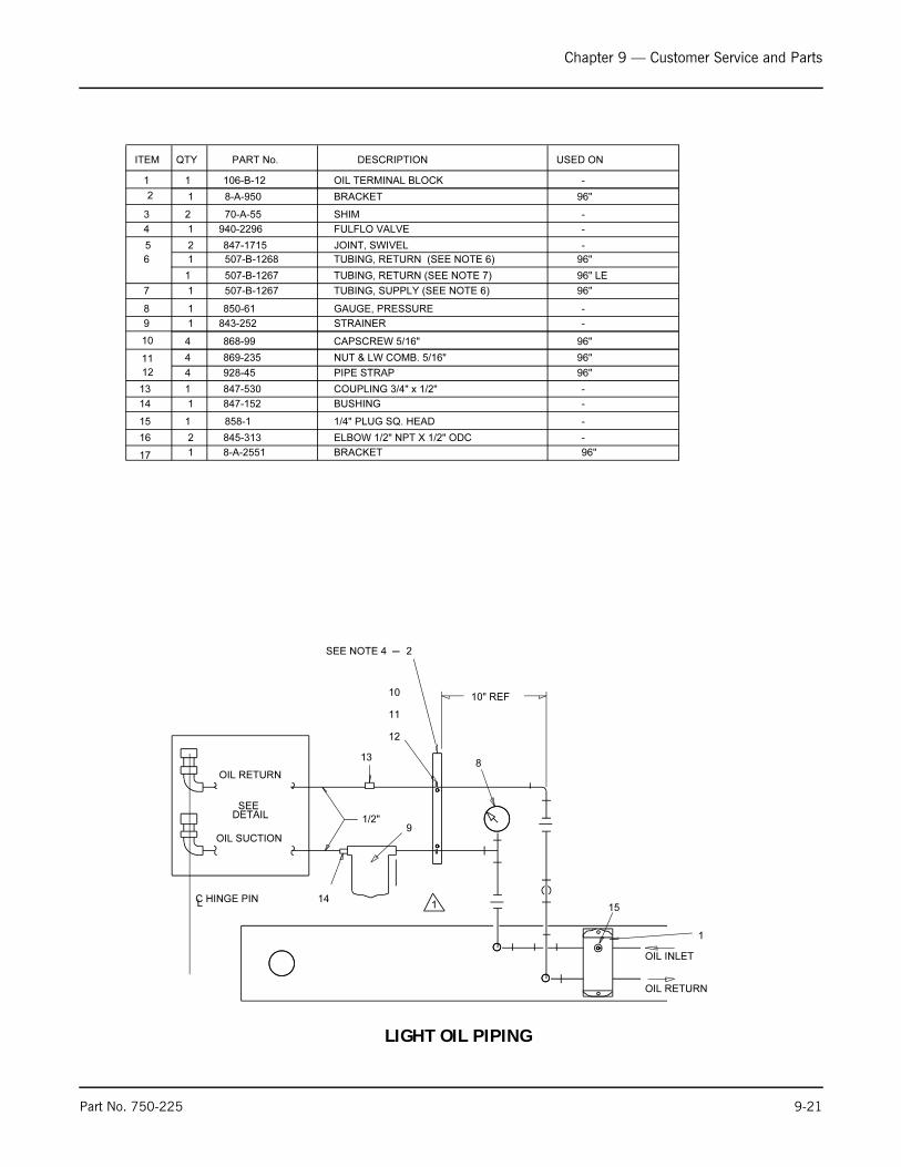
Chapter 9 — Customer Service and Parts
Part No. 750-225 9-21
OIL RETURN
OIL INLET
8
1
1/2"DETAILSEE
OIL TERMINAL BLOCK106-B-1211
DESCRIPTIONPART No.QTYITEM
OIL SUCTION
OIL RETURN
1415
2
3 2 70-A-55 SHIM
4 1 940-2296 FULFLO VALVE
5 2 847-1715 JOINT, SWIVEL
6
7
8 1 850-61 GAUGE, PRESSURE
9 1 843-252 STRAINER
10
11
12 928-45 PIPE STRAP
13 847-530 COUPLING 3/4" x 1/2"
1/4" PLUG SQ. HEAD858-115
BUSHING847-15214
1
1
1
4
13
1 507-B-1268
507-B-12671 TUBING, SUPPLY (SEE NOTE 6)
TUBING, RETURN (SEE NOTE 6)
USED ON
-
-
-
96"
-
-
96"
96"
-
-
-
-
1 8-A-950 96"BRACKET
-216 845-313 ELBOW 1/2" NPT X 1/2" ODC
C HINGE PINL
BRACKET8-A-255117 1 96"
96"
96"
4
4 NUT & LW COMB. 5/16"869-235
CAPSCREW 5/16"868-99
2
12
10
11
10" REF
SEE NOTE 4
9
1
96" LETUBING, RETURN (SEE NOTE 7)507-B-12671
LIGHT OIL PIPING

Chapter 9 — Customer Service and Parts
9-22 Part No. 750-225
9
10
8
8
192
111718
1
1/8" NPT21
20
11
22
37
3/4" x 1/2" x 1/2"
33-1/2" TO VERTICAL C
OF HEAD (REF.)
L
3/4" NPT
1/2" PLUG
CONTROLLERFUEL OIL
UNION 1/2" NPT
32
1/4" NPT
15
30
TO PILOT
35 4 5
SEE NOTE 5
29
HAWK REQUIRMENT
3-1/2"
9"
FRONT HEAD
SUPPLY
RETURN
SEE NOTE 6
15
3334
15
63627
TO BURNER
3837,TO PILOT
OIL/AIR PIPING-FRONT HEAD (LIGHT OIL)

Chapter 9 — Customer Service and Parts
Part No. 750-225 9-23
1
1
1
30 SENSOR - PRESSURE
CAM BODY GUIDE31
BUSHING - 1/2" x 1/4"32 847-419
36-A-26
817-2098
8
7
6
5
4
3
24-87
24-88
24-89
739-74
948-153 VALVE - SOLENOID 1/4"
739-79 VALVE ASSEMBLY (739-D-73)
VALVE ASSEMBLY (739-D-73)
VALVE STEM (24-A-81)
1 VALVE STEM (24-A-81)
VALVE STEM (24-A-81)
DESCRIPTIONPART NO.
QTY
ITEM
MODELS FOR 100 & 200 CB400-800
BASIC BILL OF MATERIAL
BUSHING - ARMORED CABLE 3/8"
848-16
CONNECTOR MALE - 1/4" NPT x 1/4" ODC845-7
TUBING - ASSEMBLY
8-B-22041
ELBOW - 1/4" ODC x 1/8" NPT
1 858-113 COUPLING 1/8"
1 507-A-2845
1
859-1151
COUPLING - FULL 1/2"
1
1 845-42
507-A-2847
82-B-83
ELBOW - STREET 1/8" x 4527
SPRING - COMPRESSION
TUBING - ASSEMBLY
17
18
20
21
23
15
14
11
9
GREENFIELD - 3/8" (CUT TO FIT)
848-100
827-6
948-1551
ORIFICE BLOCK106-A-491
CONNECTOR - MALE 1/4" ODC x 1/8" NPT845-4292
2
1 858-360
845-313
VALVE - SOLENOID 1/2"
ELBOW - MALE 1/2" NPT x 1/2" ODC
16
BRACKET
U-BOLT WITH NUTS
952-92
841-11191
425
24
26
1
868-1362
WASHER
1 861-439
861-436
CAPSCREW
21
1
1
1
1
1
1
CONNECTOR - SQUEEZE TYPE 3/8" x 9027
USED ON
FLEXIBLE HOSE
FLEXIBLE HOSE -
-
ADD QTY. 2 IF FM INS.
-
-
-
-
-
-
-
ADD QTY. 1 IF FM INS.
-
-
-
-
-
-
-
MODEL 100; STD/FM INS.
ADD QTY. 2 IF FM INS.
500-700 HP
800 HP
400-700 HP
800 HP
MODEL 100
400 HP
1 949-183 HYDROMOTOR VALVE 1/2" (SEE NOTE 10) FM/IRI INSURANCE
ALL EXCEPT FM INS.
-ATOMIZING AIR SWITCH507-A-20721
-AIR MANIFOLD BLOCK106-A-118
OIL COM
1
1
1
1
6 4
4
23
6
MODEL 100; IRI ONLY
MODEL 100; IRI ONLY
MODEL 100; IRI INS.
VALVE - SOLENOID 1/4"948-153
VALVE - GATE 1/4"941-914
ELBOW 1/4"NPT X 1/4"ODC845-9
NO INSURANCE948-1551 VALVE - SOLENOID 1/2"
HAWK ONLY
-
HAWK ONLY
33
34
1 817-1264 LOPS (SEE NOTE 8) -
1 817-922 HOPS (SEE NOTE 8) KEM. ONLY
-PIPE, 3/4" X 20-1/2" LG. T.B.E.57-50501
MODEL 100TUBING, OIL TO PILOT507-B-15711
36
37
38
1 845-7 CONNECTOR 1/4" NPT X 1/4" ODC. MODEL 100
1 507-A-1309 TUBING, AIR TO PILOT MODEL 100
-COUPLING, STEEL, 1/2" NPT157-A-2011
-NOZZLE, 30, H.V.MON. #F-80, 24 GPH.899-511
41
40
39 1 899-14 STRAINER, MONARCH #F-80 -
**
35
31
DETAIL "A-A"
18
1
SEE NOTE 9
403912
DETAIL B-B " "
3. ALL DIMENSIONS ARE APPROX.
PROVIDE OIL PILOT PIPING AS SHOWN.
2. IF MODEL 100, REMOVE PLUG AND
RETURN LINE PIPING DOES NOT CHANGE.
32), AND PIPE PER HAWK REQUIRMENT.
HAWK COMPONENTS (ITEMS 30 AND
OIL SUPPLY PIPING BY ADDING
1. WHEN HAWK IS REQUIRED CHANGE
NOTES:
4. USED ONLY ON FM INSURANCE.
5. USED ONLY ON IRI INSURANCE.
6. FOR SUPPLY & RETURN PIPING,
7. FOR AIR COMPRESSOR PIPING TO AIR
MANIFOLD BLOCK
8. ITEMS #33 & 34 ARE NOT USED WITH HAWK.
9. STAMP NOZZLE SIZE ON FLAT SIDE OF ITEM 12.ITEMS 12, 39, 40, & 41 STOCKED AS: 277-121
10. FM INSURANCE REQUIRES 2 MOTORIZED VALVES
W/POC ITEM 14.
*
10
10
9
8
8
25 26
23
2524
1/2" NPT
1/2" NPT
17 11
16
13
FRONT HEAD
TO BURNER
28
SEE NOTE 2
14
9
SEE NOTE 4
98 10
TYP. (2)PLACES
1-1/2"
OIL/AIR PIPING-FRONT HEAD (LIGHT OIL)
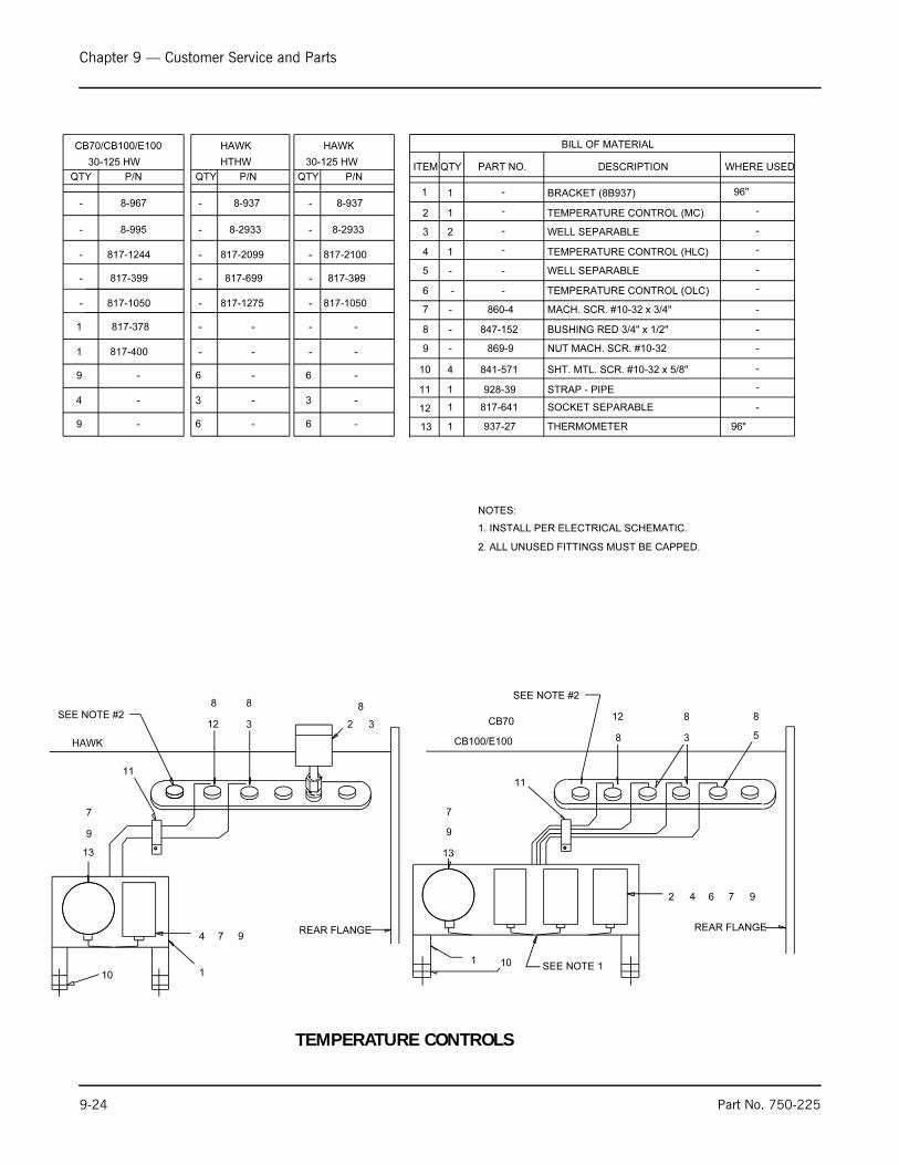
Chapter 9 — Customer Service and Parts
9-24 Part No. 750-225
5
8
3
12
8
REAR FLANGE
SEE NOTE 1
97642
7
9
13
1. INSTALL PER ELECTRICAL SCHEMATIC.
NOTES:
WELL SEPARABLE
847-152 BUSHING RED 3/4" x 1/2"
817-1050
4 1
8
9
10 841-571
869-9
860-4
928-39
817-399
12
2
11
TEMPERATURE CONTROL (HLC)
MACH. SCR. #10-32 x 3/4"
NUT MACH. SCR. #10-32
SHT. MTL. SCR. #10-32 x 5/8"
STRAP - PIPE
7
1 SOCKET SEPARABLE
TEMPERATURE CONTROL (OLC)
1
6
817-400
817-641
817-1244
817-378
5
1
WELL SEPARABLE
BILL OF MATERIAL
TEMPERATURE CONTROL (MC)1
3
2
1
DESCRIPTIONPART NO.QTYITEM
-
-
1
4
-
8
312
8
1
974
7
9
13
P/N
817-2099
817-1275
P/N
2 3
817-699
HTHW 30-125 HW
817-2100
817-1050
817-399
8-29338-2933
1 10
REAR FLANGE
HAWK CB100/E100
10
CB70/CB100/E100
P/N
-
-
-
---
- - -
- - -
--
QTY QTY QTY
-
-
-
-
9
9
4 3
6
6
-
-
-
-
-
-
3
6
6
-
-
-
-
-
HAWKHAWK
8-995
-
-
-
-
-
-
-
-
1111
30-125 HW
88SEE NOTE #2
SEE NOTE #2
2. ALL UNUSED FITTINGS MUST BE CAPPED.
-
-
-
-
-
-
-
-
-
-
-
WHERE USED
96"1 THERMOMETER937-2713
96"-1 BRACKET (8B937)8-967 --- 8-937 8-937
CB70
TEMPERATURE CONTROLS

Chapter 9 — Customer Service and Parts
Part No. 750-225 9-25
PRESSURE GAUGE
TEMPERATURE GAUGE
LOW WATER CUT-OFF
CONTROL, WATER LEVEL PROBE TYPE, MDL. 750
VALVE, GLOBE, 1/4"
COCK, UNION, BRASS
PRESSURE GAUGE
LOW WATER CUT-OFF
USED ON
15 ST
150-200 ST/150 HTHW
250 ST
15 ST
150 ST
200-250 ST
ABOVE 250F HW
15-200 ST1 941-1790 VALVE, BALL 3/4"
10
7
3
4
5
6
250-300 ST
15-200 ST
78" & 96" CB,CBW,CEW
15-250 ST
ALL HW
1 851-44 GAUGE, GLASS
81 825-352 SET, GAUGE GLASS
1 941-55 VALVE, BALL 1/4"
1 941-318
817-2348
BRACKET, STEAM GAUGE8-A-17281
825-311
COCK, UNION, BRASS825-312
1
817-3041
817-941
2
LOW WATER CUT-OFF 817-951
1
850-1501
850-1041
1
PRESSURE GAUGE850-2641
DESCRIPTIONPART NO.
QTYITEM
17
14
5
1"
6"
"C"
"A"
PRESSURE CB 96"
** "C"
"B"
"D" ALL
ALL
ALL
150-300# ST
15# ST 0"*
28-1/2"
27-1/2"
3
15
16
4
13
SEE NOTE 3
ALL HW
1 850-103 125 HWTEMPERATURE GAUGE
850-101 30 HW
26
27
1" @ 150#
2328
LC
LC LC
VIEW A - A
"A"
MEASURE FROM TOP OF
1ST. VIS. POINT:
"E"A.L.W.C.O.
CASTING MARK
"E" 150-250# ST
15# ST 1/2"
1"
SEE NOTE 8
25
A.L.W.C.O. M D. M.
A.L.W.C.O. MAGNETROL
25
OR LESS
OR LESS
1" @ 150#
DETAIL B - B
A.L.W.C.O.
SEE DETAIL B - B
6"
L.W.C.O.
SEE DETAIL
1
27
1"
1" ABOVE
15#
1 850-172 300 STPRESSURE GAUGE
817-163
817-163
1 300 ST
VALVE, GLOBE 3/4"941-4012 300 ST
2 941-318 300 STVALVE, GLOBE 1/4", BRASS
M D. M. MAGNETROL
817-1962
817-163
LOW WATER CUT-OFF
851-38 15-150 ST
15-250 ST
200-250 ST
300 ST
GAUGE, GLASS
SET, GAUGE GLASS
851-321
825-3571
1
3"
3-1/2"
11 1 8-A-868 BRACKET, PRESS. CONTROL
12 * CHAIN SASH 830-28
CASTING MARKL.W.C.O.
L.W.C.O. CASTING MARK:
WASHINGTON D.C. CODE
15# ST AND HW
150#-300# ST
@
@@
1"
1-1/4" X 1-1/4" X 1"1" "A"
"A"
"F"
54"
ALL HW 27"
200-300# ST 27-5/8"
150# ST 28-3/8"
15# ST 24"
C-C
"F"
"B"
L.W.C.O. CASTING MARK
1
851-199
GAUGE, GLASS 300 ST
4 912-34 912-34 ROD, GAUGE GLASS 15-150 ST ONLY
200-250 ST ONLYROD, GAUGE GLASS912-34912-854
15-300 ST
15-300 ST
851-38
+ 1/4"- 0" (TOLERANCE)
(TOLERANCE)- 0"+ 1/4"
1"ALL HW
(1 @ FINAL ASSY.)
*
250 ST1 941-401 VALVE, GLOBE 3/4"
""
""
""
" "
REF.
HIGHEST ROW OF TUBES
TOP OF CB
REF.
REMOTE SENSOR, PROBE HOLDER, MDL. 750
817-2305
ONLY
LOW WATER CUT-OFF (850-M PROBE)
817-2306
PROBE EXT., 24"LG, FOR REMOTE SENSOR, MDL. 750817-2307
1
1
1
0-160 PSI.(UP TO 250F) HW
2ABOVE 250F HW ONLY
2ABOVE
47-3/8"ALL"C"
CBLE 96"PRESSURE
1 8-A-3172 BRACKET, STEAM GAUGE LH MOUNTING 78" & 96" LE
** FOR LE USE DIM "C" TABLE BELOW.
8-31811 BRACKET, STEAM GAUGE RH MOUNTING 78" & 96" LE
1
250F HW ONLY
W.C.-MAIN & AUX. CB
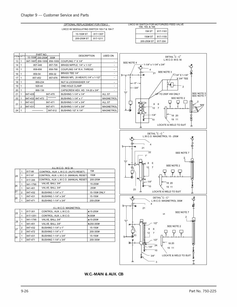
Chapter 9 — Customer Service and Parts
9-26 Part No. 750-225
-
-
-
ITEM QTYPART NO.
DESCRIPTION
857-452
859-54
858-856
857-44814 BRASS NIPPLE, 1/4" x 1-1/2"
COUPLING 1/4" R.H. THREAD
BRASS TEE 1/4"
17 BRASS NPL. (X-HEAVY) 1/4" x 1-1/2"
13 COUPLING 1" X 1/4"
-
15
16
22
21
-
-
-
ONE-HOLE CLAMP928-4419
BUSHING 1-1/4" x 1/4"
CAPSCREW HEX. HD. 1/4-20 x 3/4"20 868-136
847-428
18 NUT & LOCKWASHER 1/4"869-234
ALL ST
USED ON
1
1
1
1
1
1
1
1
1
2
1
1
15-150# ONLY
15-200#
847-432
941-1790
817-9725 CONTROL, AUX. L.W.C.O. (MANUAL RESET)
VALVE, BALL 3/4"
BUSHING 1-1/4" x 1"
150#
26
27
A.L.W.C.O. M D. M.
1 ALL ST847-431 BUSHING 1-1/4" x 3/4"23
28BUSHING 1-1/4" x 3/4"847-431 15-150# 1
200-250#817-3061
1 941-401 VALVE, BALL 3/4"
CONTROL, AUX. L.W.C.O. (MANUAL RESET)
SEE NOTE 5
L.W.C.O. MAGNETROL 300#
1/4"
12
8
7
6
"D"
21
4
1-1/4" x 1-1/4" x 3/4"
5"
3/4"
SEE NOTE 2
6
SEE NOTE 7
10
1/4"
7
8
12
L.W.C.O. M D. M.
2
SEE NOTE 3
SEE NOTE 4
21
4
"D"
SEE NOTE 2
18
19
20
11
LOCATE & WELD TO SUIT
2
10
DETAIL C - C
DETAIL C - C
23
22
1"
23
10
2
SEE NOTE 2
"D"
4
21
6
7
8
12
1/4"
L.W.C.O. MAGNETROL 15 - 250#
1/2"
1/2"
24
3/4"
3
CONTROL, AUX. L.W.C.O. 1 817-1251 300#
1 817-301 CONTROL, AUX. L.W.C.O. 15-250#
250-300#941-4011
1 847-431 BUSHING 1-1/4" x 3/4"28
A.L.W.C.O. MAGNETROL
27BUSHING 1-1/4" x 1"
25
941-1790
847-472
15-200#
200-300#
1
2
2 15-150#847-432 BUSHING 1-1/4" x 1"
15-150# 200-250# 300#
858-1009
847-470
847-471
857-726
858-768
859-32
857-676
SEE NOTE 7
SEE NOTE 7
BUSHING 1-1/4" x 1" MAGNETROL847-472847-4321
2 847-431 847-471 BUSHING 1-1/4" x 3/4" MAGNETROL
1 200-250# 847-471 BUSHING 1-1/4" x 3/4"
BUSHING 1-1/4" x 3/4"847-4711
15-150#
200-300#
MAGNETROLBUSHING 1/2" X 1/4"847-612124
-
LOCATE & WELD TO SUIT
11
20
19
18
LOCATE & WELD TO SUIT
11
20
19
18
VALVE, BALL 3/4"
VALVE, BALL 3/4"
847-1687 858-1009
15#CONTROL, AUX. L.W.C.O. (AUTO RESET) 817-981
DETAIL C - C
OPTIONAL REPLACEMENT FOR ITEM 2
LWCO W/ MODULATING SWITCH 193-7 & 194-7
15-150# ST 817-1307
200-250# ST 817-1211
LWCO W/ SWITCH FOR MOTORIZED FEED VALVE 158, 193, & 194
15# ST 817-1161
150# ST 817-1155
200-250# ST 817-304
1-1/4" X 1-1/4"
2
UP TO 250F HW ONLY
X 3/4" TEE
" "
""
" "
250#
26
W.C.-MAIN & AUX. CB