model cvs303 - the home depot regulations must be followed on all installations of this type. 1 102...
TRANSCRIPT
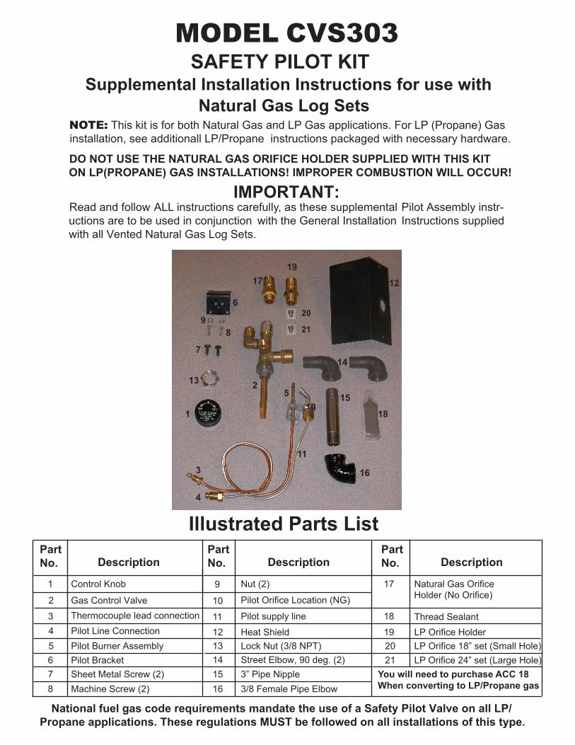
MODEL CVS303
Supplemental Installation Instructions for use with Natural Gas Log Sets
NOTE: This kit is for both Natural Gas and LP Gas applications. For LP (Propane) Gas installation, see additionall LP/Propane instructions packaged with necessary hardware.
DO NOT USE THE NATURAL GAS ORIFICE HOLDER SUPPLIED WITH THIS KIT ON LP(PROPANE) GAS INSTALLATIONS! IMPROPER COMBUSTION WILL OCCUR!
IMPORTANT:Read and follow ALL instructions carefully, as these supplemental Pilot Assembly instr-
uctions are to be used in conjunction with the General Installation Instructions supplied with all Vented Natural Gas Log Sets.
National fuel gas code requirements mandate the use of a Safety Pilot Valve on all LP/Propane applications. These regulations MUST be followed on all installations of this type.
1
2
3
6
PartNo. Description
45
78
PartNo.
PartNo.Description Description
Gas Control ValveThermocouple lead connectionPilot Line ConnectionPilot Burner AssemblyPilot Bracket
9
10
1112
141516
Sheet Metal Screw (2)Machine Screw (2)
Nut (2)
Pilot Orifice Location (NG)
Heat ShieldLock Nut (3/8 NPT)Street Elbow, 90 deg. (2)
17
18
Natural Gas Orifice Holder (No Orifice)
2021
SAFETY PILOT KIT
Thread Sealant
Illustrated Parts List
19
Control Knob
Pilot supply line
3” Pipe Nipple3/8 Female Pipe Elbow
LP Orifice Holder
1
2
3
4
5
6
7
89
10
11
12
13
14
15
16
17
18
19
13
20
LP Orifice 18” set (Small Hole)LP Orifice 24” set (Large Hole)
You will need to purchase ACC 18 When converting to LP/Propane gas
21
INSTALLATION ON DUAL BURNER SYSTEMS
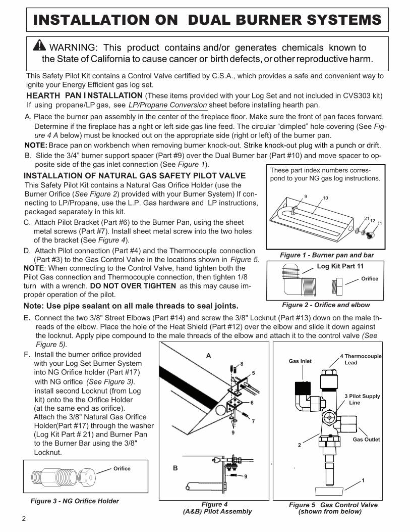
D. Attach Pilot connection (Part #4) and the Thermocouple connection (Part #3) to the Gas Control Valve in the locations shown in Figure 5.
Figure 5Figure 4(A&B) Pilot Assembly
A
5
7
9
9B
2
2
4 Thermocouple Lead
3 Pilot Supply Line6
8
1
Gas Control Valve(shown from below)
Gas Inlet
Gas Outlet
WARNING: This product contains and/or generates chemicals known to the State of California to cause cancer or birth defects, or other reproductive harm.
HEARTH PAN I NSTALLATION (These items provided with your Log Set and not included in CVS303 kit)If using propane/LP gas, seeA. Place the burner pan assembly in the center of the fireplace floor. Make sure the front of pan faces forward.
LP/Propane Conversion sheet before installing hearth pan.
Determine if the fireplace has a right or left side gas line feed. The circular “dimpled” hole covering (See Fig-ure 4 A below) must be knocked out on the appropriate side (right or left) of the burner pan.
Brace pan on workbench when removing burner knock-out. Strike knock-out plug with a punch or drift.NOTE:
9 10
112112
B. Slide the 3/4” burner support spacer (Part #9) over the Dual Burner bar (Part #10) and move spacer to op- posite side of the gas inlet connection (See Figure 1).INSTALLATION OF NATURAL GAS SAFETY PILOT VALVE
This Safety Pilot Kit contains a Control Valve certified by C.S.A., which provides a safe and convenient way to ignite your Energy Efficient gas log set.
Figure 1 - Burner pan and bar
Figure 2 - Orifice and elbow
This Safety Pilot Kit contains a Natural Gas Orifice Holder (use the Burner Orifice (See Figure 2) provided with your Burner System) If con-necting to LP/Propane, use the L.P. Gas hardware and LP instructions,packaged separately in this kit. C. Attach Pilot Bracket (Part #6) to the Burner Pan, using the sheet metal screws (Part #7). Install sheet metal screw into the two holes of the bracket (See Figure 4).
NOTE: When connecting to the Control Valve, hand tighten both the Pilot Gas connection and Thermocouple connection, then tighten 1/8 turn with a wrench. DO NOT OVER TIGHTEN as this may cause im-
E. Connect the two 3/8" Street Elbows (Part #14) and screw the 3/8" Locknut (Part #13) down on the male th- reads of the elbow. Place the hole of the Heat Shield (Part #12) over the elbow and slide it down against the locknut. Apply pipe compound to the male threads of the elbow and attach it to the control valve (See Figure 5).F. Install the burner orifice provided with your Log Set Burner System into NG Orifice holder (Part #17) with NG orifice (See Figure 3)..
Attach the 3/8" Natural Gas Orifice Holder(Part #17) through the washer (Log Kit Part # 21) and Burner Pan to the Burner Bar using the 3/8" Locknut.
Note: Use pipe sealant on all male threads to seal joints.
Figure 3 - NG Orifice Holder
Orifice
These part index numbers corres-pond to your NG gas log instructions.
proper operation of the pilot.
install second Locknut (from Logkit) onto the the Orifice Holder (at the same end as orifice).
Orifice
Log Kit Part 11
G.
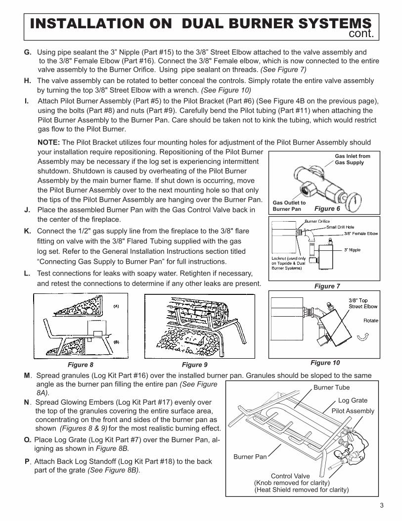
(See Figure 7) H. The valve assembly can be rotated to better conceal the controls. Simply rotate the entire valve assembly
by turning the top 3/8" Street Elbow with a wrench. (See Figure 10)I. Attach Pilot Burner Assembly (Part #5) to the Pilot Bracket (Part #6) (See Figure 4B on the previous page),
using the bolts (Part #8) and nuts (Part #9). Carefully bend the Pilot tubing (Part #11) when attaching the Pilot Burner Assembly to the Burner Pan. Care should be taken not to kink the tubing, which would restrict
NOTE: The Pilot Bracket utilizes four mounting holes for adjustment of the Pilot Burner Assembly should your installation require repositioning. Repositioning of the Pilot Burner Assembly may be necessary if the log set is experiencing intermittent shutdown. Shutdown is caused by overheating of the Pilot Burner Assembly by the main burner flame. If shut down is occurring, move the Pilot Burner Assembly over to the next mounting hole so that only the tips of the Pilot Burner Assembly are hanging over the Burner Pan.
J. noC saG eht htiw naP renruB delbmessa eht ecalP trol Valve back in the center of the fireplace.
K. Connect the 1/2" gas supply line from the fireplace to the 3/8" flare fitting on valve with the 3/8" Flared Tubing supplied with the gas log set. Refer to the General Installation Instructions section titled “Connecting Gas Supply to Burner Pan” for full instructions.
L. Test connections for leaks with soapy water. Retighten if necessary,and retest the connections to determine if any other leaks are present.
Figure 8
Figure 7
cont.
3
Using pipe sealant the 3” Nipple (Part #15) to the 3/8” Street Elbow attached to the valve assembly and to the 3/8" Female Elbow (Part #16). Connect the 3/8" Female elbow, which is now connected to the entire
Using pipe sealant on threads.
Gas Inlet from Gas Supply
Gas Outlet to Burner Pan Figure 6
INSTALLATION ON DUAL BURNER SYSTEMS
Burner Tube
(Heat Shield removed for clarity)
Control Valve(Knob removed for clarity)
Burner Pan
Log GratePilot Assembly
Figure 10Figure 9
N . Spread Glowing Embers (Log Kit Part #17) evenly over the top of the granules covering the entire surface area, concentrating on the front and sides of the burner pan as shown for the most realistic burning effect. (Figures 8 & 9)
.
P.
. Place Log Grate (Log Kit Part #7) over the Burner Pan, al- igning as shown in Figure 8B.
O.
Attach Back Log Standoff (Log Kit Part #18) to the back part of the grate (See Figure 8B).
M. Spread granules (Log Kit Part #16) over the installed burner pan. Granules should be sloped to the same angle as the burner pan filling the entire pan (See Figure 8A).
valve assembly to the Burner Orifice.
gas flow to the Pilot Burner.
4
LIGHTING YOUR GAS LOGS WITH THE SAFETY PILOT KIT1. Light Pilot
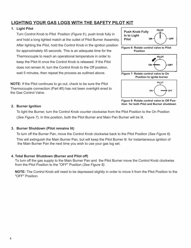
Turn Control Knob to Pilot Position (Figure 6 ), push knob fully in and hold a long lighted match at the outlet of Pilot Burner Assembly.After lighting the Pilot, hold the Control Knob in the ignition position for approximately 45 seconds. This is an adequate time for the Thermocouple to reach an operational temperature in order to keep the Pilot lit once the Control Knob is released. If the Pilot does not remain lit, turn the Control Knob to the Off position, wait 5 minutes, then repeat the process as outlined above.
NOTE: If the Pilot continues to go out, check to be sure the Pilot Thermocouple connection (Part #5) has not been overtight ened to the Gas Control Valve.
2. Burner IgnitionTo light the Burner, turn the Control Knob counter clockwise from the Pilot Position to the On Position (See Figure 7). In this position, both the Pilot Burner and Main Pan Burner will be lit.
3. Burner Shutdown (Pilot remains lit)To turn off the Burner Pan, move the Control Knob clockwise back to the Pilot Position (See Figure 6).This will extinguish the Main Burner Pan, but will keep the Pilot Burner lit for instantaneous ignition of the Main Burner Pan the next time you wish to use your gas log set.
4. Total Burner Shutdown (Burner and Pilot off)To turn off the gas supply to the Main Burner Pan and the Pilot Burner move the Control Knob clockwise from the Pilot Position to the "OFF" Position (See Figure 8).
NOTE: The Control Knob will need to be depressed slightly in order to move it from the Pilot Position to the "OFF" Position.
Figure 6- Rotate control valve to Pilot Position
Figure 7- Rotate control valve to On Position to ignite burner
Figure 8- Rotate control valve to Off Pos-ition for both Pilot and Burner shutdown
PILOT
ON OFF
Push Knob Fully In to Light Pilot
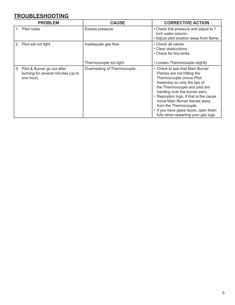
TROUBLESHOOTINGPROBLEM CAUSE CORRECTIVE ACTION
1. Pilot noise Excess pressure • 7 ot tsujda dna erusserp enil kcehC inch water column.
• Adjust pilot location away from flame.2. Pilot will not light Inadequate gas flow
Thermocouple too tight
• Check all valves• Clear obstructions• Check for line kinks
• Loosen Thermocouple slightly3. retfa tuo og renruB & toliP
burning for several minutes (up to one hour)
Overheating of Thermocouple • renruB niaM taht ees ot kcehC Flames are not hitting the Thermocouple (move Pilot Assembly so only the tips of the Thermocouple and pilot are handing over the burner pan).
• ,esuac eht si taht fi ,sgol noitisopeR move Main Burner flames away from the Thermocouple.
• meht nepo ,srood ssalg evah uoy fI fully when opearting your gas logs.
5
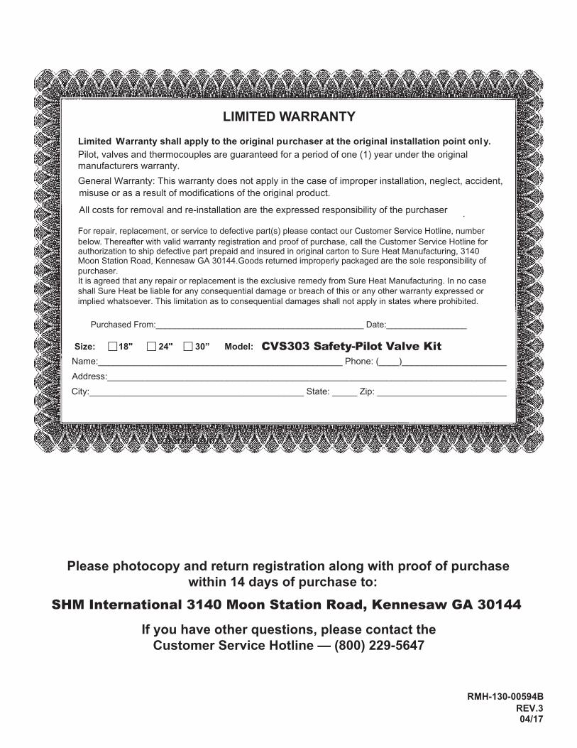
LIMITED WARRANTYLimited Warranty shall apply to the original purchaser at the original installation point only.Pilot, valves and thermocouples are guaranteed for a period of one (1) year under the original manufacturers warranty. General Warranty: This warranty does not apply in the case of improper installation, neglect, accident, misuse or as a result of modifications of the original product.
All costs for removal and re-installation are the expressed responsibility of the purchaser .
For repair, replacement, or service to defective part(s) please contact our Customer Service Hotline, number below. Thereafter with valid warranty registration and proof of purchase, call the Customer Service Hotline for authorization to ship defective part prepaid and insured in original carton to Sure Heat Manufacturing, 3140 Moon Station Road, Kennesaw GA 30144.Goods returned improperly packaged are the sole responsibility of purchaser. It is agreed that any repair or replacement is the exclusive remedy from Sure Heat Manufacturing. In no case shall Sure Heat be liable for any consequential damage or breach of this or any other warranty expressed or implied whatsoever. This limitation as to consequential damages shall not apply in states where prohibited.
Purchased From:____________________________________________ Date:_________________
Size: 18" 24" 30” Model:Name:_________________________________________________ Phone: (____)_____________________Address:________________________________________________________________________________City:___________________________________________ State: _____ Zip: __________________________
Please photocopy and return registration along with proof of purchasewithin 14 days of purchase to:
SHM International 3140 Moon Station Road, Kennesaw GA 30144
If you have other questions, please contact the Customer Service Hotline — (800) 229-5647
RMH-130-00594B
04/17REV.3
CVS303 Safety-Pilot Valve Kit
Lorem ipsum