model da8 - cashco.s3.amazonaws.comcashco.s3.amazonaws.com/2016/03/14/16/49/59/308/da8.pdf · sizes...
TRANSCRIPT

MODEL DA8DO-ALL SERIES VIII
DIFFERENTIAL BACK PRESSURE REGULATOR
Spring Operated: 1/2" – 4" (DN15 - 100)
The Model DA8 is a differential back pressure regulators used to maintain a constant pressure differential between a fluid loading pressure (PLOAD) piped to the spring chamber and the regulator’s inlet pressure (P1). In the Model DA8 the P1 pressure is higher than the PLOAD (Positive Bias). The amount of bias or differential pressure (∆PDiff) is controlled by the user adjustable setting of the range spring in the spring chamber.
The regulator uses a flow-to-open, cage balanced trim. The diaphragm is isolated from the fluid flow path by a balanc-ing piston, which allows the user to specify either internal or external sensing of the P1 pressure.
FEATURES
Versatile: Four basic materials and multiple trim ma te ri al combinations to select from.
Tight Shutoff: Multiple composition materials pro vide Class IV or VI inboard leak age rates. Designed as a soft-seat ed valve.
Capacity: Highest in the industry. Allows small er body sizes than competitors in ma jor i ty of applications.
Pressure Drop: Highest in the industry when cou pled with high flow capacity.
Trim Design: “DO-ALL” trim design provides FTO and pressure balancing for higher in let pres sure. Results in unmatched sensitiv-ity and stability. Internals are cage-con-
tained within easily re mov able quick change trim.
Rangeability: Basic valve gives outstanding range-ability due to close tolerances, balanced trim, and a broad range of elastomeric diaphragms and soft seats. Can be as high as 1000:1.
Heavy-Duty Both top and bottom guided to maintainGuiding: stability and increased di a phragm life.
Failure Position: DA8 fails closed on loss of P1 pressure.
TECHNICAL BULLETIN DA8-TB03-16
APPLICATIONS
The “DO-ALL” design allows application of all types of clean fluids. Designed primarily for gaseous and liquid ser vice applications where ex ces sive cavitation is absent. Ex cel lent for at mo spher ic in dus tri al gases – GN2, GOX, Ar, He, H2, CO2 – as well as a natural gas regulator. Used as a utilities – air, oil, water, steam – regulator. Non-corrosive chemical services – gas or liquid – are possible with broad materials range.
MODEL DA8
CAUTION
In the event of diaphragm failure, the process fluid will mix with the loading fluid.
ISO Registered Company
2 DA8-TB
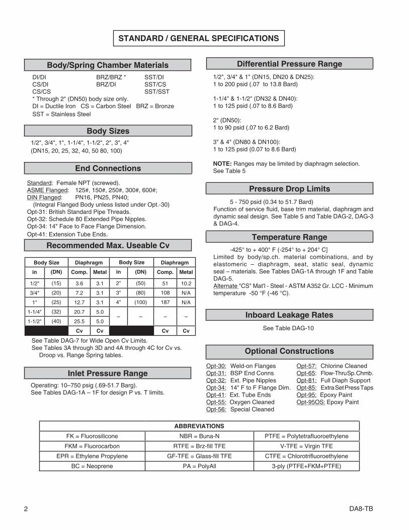
STANDARD / GENERAL SPECIFICATIONS
DI/DI BRZ/BRZ * SST/DI CS/DI BRZ/DI SST/CS CS/CS SST/SST * Through 2" (DN50) body size only. DI = Ductile Iron CS = Carbon Steel BRZ = Bronze SST = Stainless Steel
1/2", 3/4", 1", 1-1/4", 1-1/2", 2", 3", 4" (DN15, 20, 25, 32, 40, 50 80, 100)
Body Size Diaphragm Body Size Diaphragm
in (DN) Comp. Metal in (DN) Comp. Metal
1/2" (15) 3.6 3.1 2" (50) 51 10.2
3/4" (20) 7.2 3.1 3" (80) 108 N/A
1" (25) 12.7 3.1 4" (100) 187 N/A
1-1/4" (32) 20.7 5.0– – – –
1-1/2" (40) 25.5 5.0
Cv Cv Cv Cv
See Table DAG-7 for Wide Open Cv Limits.See Tables 3A through 3D and 4A through 4C for Cv vs.
Droop vs. Range Spring tables.
Operating: 10–750 psig (.69-51.7 Barg). See Tables DAG-1A – 1F for design P vs. T limits.
Differential Pressure RangeBody/Spring Chamber Materials
Body Sizes
End Connections
Recommended Max. Useable Cv
Inlet Pressure Range
1/2", 3/4" & 1" (DN15, DN20 & DN25):1 to 200 psid (.07 to 13.8 Bard)
1-1/4" & 1-1/2" (DN32 & DN40):1 to 125 psid (.07 to 8.6 Bard)
2" (DN50):1 to 90 psid (.07 to 6.2 Bard)
3" & 4" (DN80 & DN100):1 to 125 psid (0.07 to 8.6 Bard)
NOTE: Ranges may be limited by diaphragm se lec tion.See Table 5
Temperature Range
5 - 750 psid (0.34 to 51.7 Bard)Function of service fluid, base trim material, diaphragm and dynamic seal design. See Table 5 and Table DAG-2, DAG-3 & DAG-4.
Pressure Drop Limits
Inboard Leakage Rates
Optional Constructions
Opt-30: Weld-on Flanges Opt-57: Chlorine CleanedOpt-31: BSP End Conns Opt-65: Flow-Thru Sp. Chmb.Opt-32: Ext. Pipe Nipples Opt-81: Full Diaph SupportOpt-34: 14" F to F Flange Dim. Opt-85: Extra Set Press TapsOpt-41: Ext. Tube Ends Opt-95: Epoxy PaintOpt-55: Oxygen Cleaned Opt-95OS: Epoxy PaintOpt-56: Special Cleaned
-425° to + 400° F (-254° to + 204° C]Limited by body/sp.ch. material combinations, and by elas to mer ic – diaphragm, seat, static seal, dynamicseal – materials. See Tables DAG-1A through 1F and Table DAG-5.Alternate "CS" Mat'l - Steel - ASTM A352 Gr. LCC - Minimum temperature -50 °F (-46 °C).
ABBREVIATIONS
FK = Fluorosilicone NBR = Buna-N PTFE = Polytetrafl uoroethylene
FKM = Fluorocarbon RTFE = Brz-fi ll TFE V-TFE = Virgin TFE
EPR = Ethylene Propylene GF-TFE = Glass-fi ll TFE CTFE = Chlorotrifl uoroethylene
BC = Neoprene PA = PolyAll 3-ply (PTFE+FKM+PTFE)
Standard: Female NPT (screwed). ASME Flanged: 125#, 150#, 250#, 300#, 600#;DIN Flanged: PN16, PN25, PN40; (Integral Flanged Body unless listed under Opt.-30)Opt-31: British Standard Pipe Threads.Opt-32: Schedule 80 Extended Pipe Nipples.Opt-34: 14" Face to Face Flange Dimension.Opt-41: Extension Tube Ends.
See Table DAG-10

DA8-TB 3
Dynamic & Stat ic Seals
MATERIAL SPECIFICATIONS
Body
DI – ASTM A395 CS – ASTM A216, Grade WCB. Alternate ASTM A352 Gr. LCC BRZ – ASTM B62, Alloy 83600, SST – ASTM A351, Grade CF3M.
See DAG-1A through DAG-1F for material specs.
Spring Chamber
DI – ASTM A395 CS – Sizes 1/2" - 2" ASTM A216 Gr. WCB; Alternate ASTM A352 Gr. LCC Sizes 3" & 4" ASTM A516 Gr. 55, A106 Gr. B; BRZ – ASTM B62, Alloy 83600. SST – Sizes 1/2" - 2" ASTM A351 Gr. CF3M; Sizes 3" & 4" ASTM A479 Gr. 316L, A312 Gr. 316L;
Diaphragm *
Elastomeric – BC, EPR, FKM, FK, NBR, FKM+TFE,
3-ply(PTFE+FKM+PTFE).
Metallic – Be-Cu. (only 1/2" - 2" sizes)
Metallic Trim * 17-4PH SST, 316L SST, Nickel-Copper Alloy (Monel).
See Table 2.
Seat *
PolyAll, V-TFE, GF-TFE, CTFE, FKM
Static Seals (See Fig. DAG-F1) *RTFE, NBR, FKM, FK, EPR, (All Sizes)SST/TFE (1/2" - 2") (DN15 - 50)V-TFE (3" - 4") (DN80 - 100)
Dynamic Seals (See Fig. DAG-F1) *Type CP – TFE cap+ NBR, FKM, EPR o-ring seal.Type UC – V-TFE u-cup seal with 316L SST energizer.Type PR – GF-TFE piston ring assembly seal with 17-7PH SST energizer.
Painting
Standard: All non-corrosion resistant portions to be painted with corrosion resistant epoxy paint per Cashco Spec #S-1606.Alternate: See Opt-95 or Opt-95OS.
* See Product Coder for acceptable combinations MonelTM, and Inconel® are registered trade names: MonelTM is a mark owned by International Nickel Co. Inconel® is a mark owned by International Nickel Co.
Reverse Flow Direction Composition DiaphragmFTO – Flow-to-Open Balanced at Outlet
Trim Balanced to Outlet Presure Variations
FIGURE 1

4 DA8-TB
OPT-30: WELDED FLANGED CONNECTIONS. CS, SST or HC body materials only. 1/2"–2" (DN15–50) body sizes only (no 1-1/4" (DN32) size). Welded-on flange of same gen er al chem is try as body.
NOTES: 1. The body P vs. T ratings are the limiting variables for flanged end con-nections, unless fur ther restricted by ASME B16.5.
2. No post-weld stress relieving performed.
OPT-31: BSP END CONNECTIONS. British Stan dard Pipe threads per ISO 7/1; used as an al ter nate to NPT ends. 1/2" – 2" (DN15–50) sizes only.
OPT-32: EXTENDED PIPE NIPPLES. Sch. 80 ex ten- sion pipe nipples available for CS and SST bodies; for body sizes 1/2" – 2" (DN15–50) only.
OPT-34: SPECIAL 14" FACE TO FACE DIMEN-SION FOR FLANGED END CON NEC- TIONS. Sizes 1/2" - 1" & 1-1/2" only. See Opt.-30 for standard face to face dimension.
OPT-41: EXTENDED TUBE END CONN. SST body material only. Body sizes 1/2"–1" (DN15–25),
1-1/2" & 2" (DN40–50) only. SST ex ten- sion tubes are weld ed to body, ending in tube di am e ters with 0.065 inch (1.65 mm) wall thick ness. NOT FOR HIGH PU RI TY REQUIREMENTS.
OPT-55: SPE CIAL CLEAN ING - GOX. BRZ or SST body ma te ri als only. Cleaning, assembly and pack ag ing per Cashco Spec #S-1134, making unit suitable for Oxygen Service. NOTE: Design Pressure Rating shall not ex ceed 375 psig (25.8 Barg) when
body/top works material is SST and pro-cess medium is oxygen.
OPTION SPECIFICATIONS
OPT-56: SPECIAL CLEANING. Cleaning per Cashco Spec. #S-1542 for all body & spring chamber materials. Higher cleaning level than standard commercial cleaning. NOT suitable for Oxygen Service.
OPT-57: SPECIAL CLEANING - Chlorine. CS or SST ma-terials only. Cleaning per Cashco Spec. #S-1589. For chlorine gas/liquid service.
OPT-65: FLOW-THRU SPRING CHAMBER. Spring cham-ber provided with two female NPT connections on spring chamber, allowing loading pressurizing fluid to be recirculated. Recommended for heavy oils with high paraffin content. CS spring chamber only. Tapped connection sizes dependent on body size.
OPT-81: FULL DIAPHRAGM SUPPORT CONSTRUCTION. Incorporates top & bottom diaphragm support that allows reaching higher fluid pressures on the underside and topside of diaphragm. Sizes 1/2"-2" (DN15-50) only. See Table 5.
OPT-85: PRESSURE TAPS. Provides second set of inlet and outlet 1/4" (DN8) - FNPT taps with plugs (same ba sic ma te ri al as body) on back side of body. In cludes second external sensing port tap. See page 21 for details on tap location for both STD. and Opt -85.
OPT-95: EPOXY PAINT. Special epoxy painting of all non-corrosion resistant external surfaces per Cashco Spec #S-1547. Utilized in harsh atmospheric conditions.
OPT-95OS: EPOXY PAINT. Special epoxy painting of all non-corrosion resistant external surfaces per Cashco Spec #S-1687. Utilized in OFFSHORE atmospheric conditions
Weld-On Flanges
Sizes Body Material ASME Pressure Class
1/2" - 3/4" CS, SST 150, 300, 600
1" CS, SST 600
Sizes Body Material ISO Pressure Class
DN15-50 CS, SST PN40 RF
DN80-100 CS, SST PN16, 25, 40 RF^ For 1/2" - 2" sizes, CS & SST, metal diaphragm only

DA8-TB 5
TECHNICAL SPECIFICATIONS
TABLE 1RANGE SPRINGS
* Composition diaphragm construction ONLY. ** Metal diaphragm for set point pressure ≥ 5 psid (.34 Bard).
METRIC CONVERSION: psid / 14.5 = Bard
TABLE 2METALLIC TRIM MATERIAL COMBINATIONS
PARTTRIM DESIGNATION
S P M T
Plug / Guide Bearing 316L SST 17-4 PH SST Monel† 17-4 PH SST
Cage 316L SST 316L SST Monel† Monel†
Body Bushing Monel† 17-4 PH SST Monel† Monel†
† See Page 3 for registered trade name information.
Body Sizein. (DN)
Spring Rangepsid
Body Sizein. (DN)
Spring Rangepsid
1/2" (15)3/4" (20)1" (25)
1-5*1-10**
2" (50)
1-5*1-10**
5-2010-3520-80
30-15070-200
5-1510-3015-5030-90
1-1/4" (32)1-1/2" (40)
1-5*1-10**
3" (80)4" (100)
1-10
5-2015-4510-70
40-175
5-2010-4010-70
40-125

6 DA8-TB
TABLE 3AFULL PORT FLOW CAPACITY – Cv
COMPOSITION DIAPHRAGMFL = 0.90
Differential Pressure ∆P Diff (psid)
COMPOSITION DIAPHRAGM
BODY SIZE - 1/2” (DN15) BODY SIZE - 3/4” (DN20) BODY SIZE - 1” (DN25) Range Spring psid10% 20% 30% 40% 50% 10% 20% 30% 40% 50% 10% 20% 30% 40% 50%
1 1.15 1.75 2.38 2.97 3.53 1.15 1.75 2.38 2.97 3.53 1.28 2.34 3.40 4.40 5.34
1-53 2.67 2.77 2.91 3.03 3.16 3.44 3.95 4.85 5.70 6.50 3.83 5.27 6.93 8.49 9.95
5 3.52 3.54 3.56 3.58 3.60 4.97 7.14 7.16 7.18 7.20 5.53 9.60 12.70 12.73 12.75
1 0.56 0.86 1.15 1.42 1.67 0.56 0.86 1.15 1.42 1.67 0.60 1.11 1.72 2.29 2.83
1-105 2.64 3.54 3.56 3.58 3.60 2.80 4.90 6.50 7.18 7.20 3.66 5.10 6.67 8.15 9.54
10 3.52 3.54 3.56 3.58 3.60 4.76 7.14 7.16 7.18 7.20 5.23 9.15 12.10 12.73 12.75
5 2.30 3.54 3.56 3.58 3.60 2.30 4.00 5.30 6.30 7.05 2.55 4.08 5.23 6.31 7.32
5-2010 3.52 3.54 3.56 3.58 3.60 3.64 6.40 7.16 7.18 7.20 4.04 6.59 8.67 10.60 12.50
15 3.52 3.54 3.56 3.58 3.60 4.40 7.14 7.16 7.18 7.20 4.89 9.10 11.30 12.73 12.75
20 3.52 3.54 3.56 3.58 3.60 6.39 7.14 7.16 7.18 7.20 7.10 12.40 12.70 12.73 12.75
10 1.11 1.79 2.53 3.24 3.60 1.11 1.79 2.53 3.24 3.90 1.23 2.38 3.61 4.77 5.86
10-3520 1.96 2.68 3.05 3.40 3.60 2.45 3.83 5.09 6.28 7.20 2.72 5.10 7.27 9.30 11.20
30 3.18 3.54 3.56 3.58 3.60 3.98 5.87 7.16 7.18 7.20 4.42 7.82 10.30 12.10 12.75
35 3.40 3.54 3.56 3.58 3.60 4.59 6.90 7.16 7.18 7.20 5.10 8.50 11.10 12.73 12.75
20 0.84 1.40 1.94 2.44 2.91 0.84 1.40 1.94 2.44 2.91 0.94 1.87 2.76 3.60 4.39
20-8040 1.42 2.62 3.56 3.58 3.60 1.42 2.62 3.87 5.04 6.15 1.57 3.49 5.53 7.44 9.25
60 2.39 3.24 3.56 3.58 3.60 2.98 4.62 6.07 7.18 7.20 3.32 6.16 8.67 11.00 12.17
80 3.33 3.54 3.56 3.58 3.60 4.17 5.50 6.50 7.18 7.20 4.63 8.10 10.70 12.60 12.75
METRIC CONVERSION FACTORS: psid / 14.5 = Bard; Cv / 1.16 = kv
30 0.77 1.28 1.79 2.26 2.72 0.77 1.28 1.79 2.26 2.72 0.85 1.70 2.55 3.35 4.10
30-150
50 1.34 2.24 2.98 3.58 3.60 1.34 2.24 2.98 3.67 4.32 1.49 2.98 4.25 5.45 6.58
75 2.30 3.51 3.56 3.58 3.60 2.30 3.51 4.58 5.59 6.53 2.55 4.68 6.55 8.30 9.96
100 2.91 3.51 3.56 3.58 3.60 2.91 4.46 5.65 6.77 7.20 3.23 5.95 8.08 10.10 12.00
125 3.06 3.54 3.56 3.58 3.60 3.83 5.58 6.80 7.18 7.20 4.25 7.44 9.80 11.60 12.75
150 3.52 3.54 3.56 3.58 3.60 4.21 6.20 7.16 7.18 7.20 5.10 8.90 11.70 12.73 12.75
70 0.58 1.44 2.32 3.15 3.60 0.58 1.44 2.32 3.15 3.93 1.00 2.00 3.00 4.00 5.00
70-200
100 1.84 3.03 3.56 3.58 3.60 1.84 3.03 4.02 4.96 5.83 2.04 4.04 5.74 7.34 8.84
125 2.49 3.52 3.56 3.58 3.60 2.49 3.89 5.06 6.15 6.80 2.76 5.19 7.23 9.14 10.90
150 2.91 3.54 3.56 3.58 3.60 2.91 4.59 5.53 6.42 7.20 3.23 6.12 7.91 9.58 11.20
175 3.52 3.54 3.56 3.58 3.60 3.56 5.68 6.74 7.18 7.20 3.95 7.57 10.30 12.34 12.75
200 3.52 3.54 3.56 3.58 3.60 4.28 7.14 7.16 7.18 7.20 4.30 7.60 10.30 12.30 12.75

DA8-TB 7
TABLE 3BFULL PORT FLOW CAPACITY – Cv
COMPOSITION DIAPHRAGM FL = 0.90
TABLE 3CFULL PORT FLOW CAPACITY – Cv
COMPOSITION DIAPHRAGM FL = 0.90
METRIC CONVERSION FACTORS: psid / 14.5 = Bard; Cv / 1.16 = kv
Differential Pressure ∆P Diff (psid)
COMPOSITION DIAPHRAGMRange Spring psid
BODY SIZE - 1 1/4” (DN32) BODY SIZE - 1 1/2” (DN40)
10% 20% 30% 40% 50% 10% 20% 30% 40% 50%
1 1.78 2.91 3.83 4.69 5.50 1.87 3.23 4.51 5.70 6.83
1-105 3.91 6.67 9.27 11.70 14.00 4.12 7.40 11.00 14.30 17.50
10 6.16 13.30 18.50 20.00 20.70 6.72 14.00 19.00 24.00 25.50
5 2.26 4.05 5.59 7.04 8.40 2.38 4.51 6.59 8.55 10.40
5-2010 4.85 8.67 11.50 14.10 16.60 5.10 9.69 13.50 17.10 20.50
15 7.30 13.00 17.00 19.60 20.70 8.00 16.80 22.80 25.00 25.50
20 9.70 17.30 20.00 20.30 20.70 10.00 18.00 24.50 25.00 25.50
15 3.79 6.89 9.10 11.20 13.10 4.00 7.65 10.70 13.60 16.30
15-4525 6.30 11.10 14.90 18.40 19.60 6.63 12.40 17.50 22.30 25.50
35 8.76 15.20 19.60 19.60 0.00 9.27 16.90 23.40 25.00 25.50
45 11.40 19.80 20.00 20.30 20.70 12.80 21.00 24.50 25.00 25.50
15 1.80 3.00 4.20 5.30 6.30 1.95 3.20 4.50 5.75 7.10
10-7030 3.63 6.35 8.67 10.90 12.90 3.83 7.06 10.20 13.20 15.90
50 6.26 10.70 14.00 17.10 19.60 6.59 12.00 16.60 20.90 24.90
70 8.50 14.80 20.00 20.30 20.70 9.00 15.00 23.00 25.00 25.50
40 2.18 4.36 5.99 7.53 8.97 2.30 4.85 7.06 9.13 11.10
40-125
50 3.23 5.66 7.58 9.39 11.10 3.40 6.29 8.93 11.40 13.70
75 4.44 7.73 10.50 13.00 15.40 4.68 8.59 12.30 15.80 19.10
100 5.85 9.95 13.10 16.00 18.80 6.16 11.10 15.50 19.50 23.40
125 7.27 12.40 16.40 20.00 20.70 7.65 13.90 19.30 24.40 25.50
Differential Pressure
∆P Diff (psid)
COMPOSITION DIAPHRAGMRange Spring psid
BODY SIZE - 2” (DN50)
10% 20% 30% 40% 50%
1 4.25 10.60 14.90 18.90 22.60
1-105 13.90 25.70 38.30 50.00 51.00
10 22.10 41.00 49.00 50.00 51.00
5 7.23 12.80 18.30 23.50 28.40
5-1510 12.30 24.70 37.00 48.60 51.00
15 19.00 36.00 49.00 50.00 51.00
10 4.17 8.50 12.80 16.70 20.50
10-3020 10.00 17.00 27.70 37.80 47.20
30 15.00 25.00 38.00 50.00 51.00
15 2.55 5.95 9.35 12.50 15.60
15-5025 5.10 9.78 14.60 19.20 23.50
35 7.40 15.10 22.50 29.50 36.00
50 10.60 19.00 29.00 38.00 47.00
30 3.40 5.87 8.93 11.80 14.50
30-9060 6.97 12.80 18.70 24.30 29.60
90 10.20 19.00 28.00 36.00 44.00

8 DA8-TB
METRIC CONVERSION FACTORS: psid / 14.5 = Bard; Cv / 1.16 = kv
TABLE 3DFULL PORT FLOW CAPACITY – Cv
COMPOSITION DIAPHRAGM FL = 0.90
Differential Pressure ∆P Diff (psid)
COMPOSITION DIAPHRAGMRange Spring psid
BODY SIZE - 3” (DN80) BODY SIZE - 4” (DN100)
10% 20% 30% 40% 50% 10% 20% 30% 40% 50%
1 12.80 20.00 27.00 33.00 38.00 12.80 20.00 27.00 33.00 38.00
1-103 17.00 34.00 51.00 64.00 77.00 17.00 34.00 51.00 67.00 82.00
5 24.70 45.10 63.00 80.00 95.00 29.80 60.00 89.00 117.00 144.00
10 53.00 90.00 102.00 105.00 108.00 64.00 110.00 150.00 185.00 187.00
5 20.80 36.50 52.00 70.00 83.00 25.50 42.50 61.00 79.00 95.00
5-2010 38.00 74.00 98.00 104.00 108.00 40.80 78.00 102.00 124.00 145.00
15 56.00 99.00 102.00 105.00 108.00 64.00 106.00 136.00 164.00 187.00
20 77.00 100.00 102.00 105.00 108.00 85.00 150.00 180.00 184.00 187.00
10 20.00 39.60 56.00 70.00 83.00 21.30 40.80 57.00 72.00 86.00
10-4020 41.00 51.00 68.00 84.00 99.00 43.40 86.00 116.00 114.00 170.00
30 56.00 74.00 96.00 102.00 108.00 60.00 108.00 145.00 179.00 187.00
40 81.00 94.00 102.00 105.00 108.00 89.00 150.00 180.00 184.00 187.00
10 10.30 19.80 29.50 37.70 47.00 10.50 20.00 29.80 38.00 47.00
10-7030 22.00 43.00 63.00 81.00 95.00 23.40 45.10 66.00 86.00 105.00
50 37.00 72.00 100.00 104.00 108.00 41.20 80.00 112.00 143.00 171.00
70 51.00 96.00 100.00 104.00 108.00 55.00 102.00 142.00 170.00 187.00
40 19.60 35.20 46.00 57.50 68.00 21.30 36.10 48.00 60.00 71.00
40-125
50 24.40 43.20 57.00 71.00 85.00 25.10 40.80 57.00 72.00 86.00
75 33.00 55.00 75.00 94.50 108.00 34.00 57.00 78.00 98.00 117.00
100 38.00 71.00 96.00 105.00 108.00 40.80 71.00 97.00 122.00 145.00
125 47.00 89.00 102.00 105.00 108.00 48.50 90.00 126.00 158.00 186.00

DA8-TB 9
TABLE 4AFULL PORT FLOW CAPACITY – Cv
METAL DIAPHRAGM FL = 0.90
METRIC CONVERSION FACTORS: psid / 14.5 = Bard; Cv / 1.16 = kv
Differential Pressure ∆P Diff (psid)
Cv Capacity @ % DroopRange Spring psid
BODY SIZE - 1/2” (DN15) BODY SIZE - 3/4” (DN20) BODY SIZE - 1” (DN25)
10% 20% 30% 40% 50% 10% 20% 30% 40% 50% 10% 20% 30% 40% 50%
5 1.00 1.88 2.75 2.95 3.00 1.00 1.88 2.75 2.95 3.00 1.00 1.88 2.75 2.95 3.00
5-2010 1.60 2.80 2.85 2.95 3.00 1.60 2.80 2.85 2.95 3.00 1.60 2.80 2.85 2.95 3.00
15 2.00 2.80 2.85 2.95 3.00 2.00 2.80 2.85 2.95 3.00 2.00 2.80 2.85 2.95 3.00
20 2.50 2.80 2.85 2.95 3.00 2.50 2.80 2.85 2.95 3.00 2.50 2.80 2.85 2.95 3.00
10 0.55 1.03 1.51 1.99 2.45 0.55 1.03 1.51 1.99 2.45 0.55 1.03 1.51 1.99 2.45
10-3520 1.05 1.97 2.89 2.95 3.00 1.05 1.97 2.89 2.95 3.00 1.05 1.97 2.89 2.95 3.00
30 1.55 2.80 2.85 2.95 3.00 1.55 2.80 2.85 2.95 3.00 1.55 2.80 2.85 2.95 3.00
35 1.93 2.80 2.85 2.95 3.00 1.93 2.80 2.85 2.95 3.00 1.93 2.80 2.85 2.95 3.00
20 0.40 0.75 1.10 1.44 1.78 0.40 0.75 1.10 1.44 1.78 0.40 0.75 1.10 1.44 1.78
20-8040 0.80 1.50 2.20 2.89 3.00 0.80 1.50 2.20 2.89 3.00 0.80 1.50 2.20 2.89 3.00
60 1.10 2.07 2.85 2.95 3.00 1.10 2.07 2.85 2.95 3.00 1.10 2.07 2.85 2.95 3.00
80 1.50 2.80 2.85 2.95 3.00 1.50 2.80 2.85 2.95 3.00 1.50 2.80 2.85 2.95 3.00
30 0.30 0.56 0.83 1.08 1.34 0.30 0.56 0.83 1.08 1.34 0.30 0.56 0.83 1.08 1.34
30-150
50 0.50 0.94 1.38 1.81 2.23 0.50 0.94 1.38 1.81 2.23 0.50 0.94 1.38 1.81 2.23
75 0.70 1.32 1.93 2.53 3.00 0.70 1.32 1.93 2.53 3.00 0.70 1.32 1.93 2.53 3.00
100 0.95 1.79 2.61 2.95 3.00 0.95 1.79 2.61 2.95 3.00 0.95 1.79 2.61 2.95 3.00
125 1.20 2.26 2.85 2.95 3.00 1.20 2.26 2.85 2.95 3.00 1.20 2.26 2.85 2.95 3.00
150 1.40 2.63 2.85 2.95 3.00 1.40 2.63 2.85 2.95 3.00 1.40 2.63 2.85 2.95 3.00
70 0.50 0.94 1.38 1.81 2.23 0.50 0.94 1.38 1.81 2.23 0.50 0.94 1.38 1.81 2.23
70-200
100 0.80 1.50 2.20 2.89 3.00 0.80 1.50 2.20 2.89 3.00 0.80 1.50 2.20 2.89 3.00
125 1.10 2.07 2.85 2.95 3.00 1.10 2.07 2.85 2.95 3.00 1.10 2.07 2.85 2.95 3.00
150 1.30 2.44 2.85 2.95 3.00 1.30 2.44 2.85 2.95 3.00 1.30 2.44 2.85 2.95 3.00
175 1.45 2.73 2.85 2.95 3.00 1.45 2.73 2.85 2.95 3.00 1.45 2.73 2.85 2.95 3.00
200 1.60 2.80 2.85 2.95 3.00 1.60 2.80 2.85 2.95 3.00 1.60 2.80 2.85 2.95 3.00
10 DA8-TB
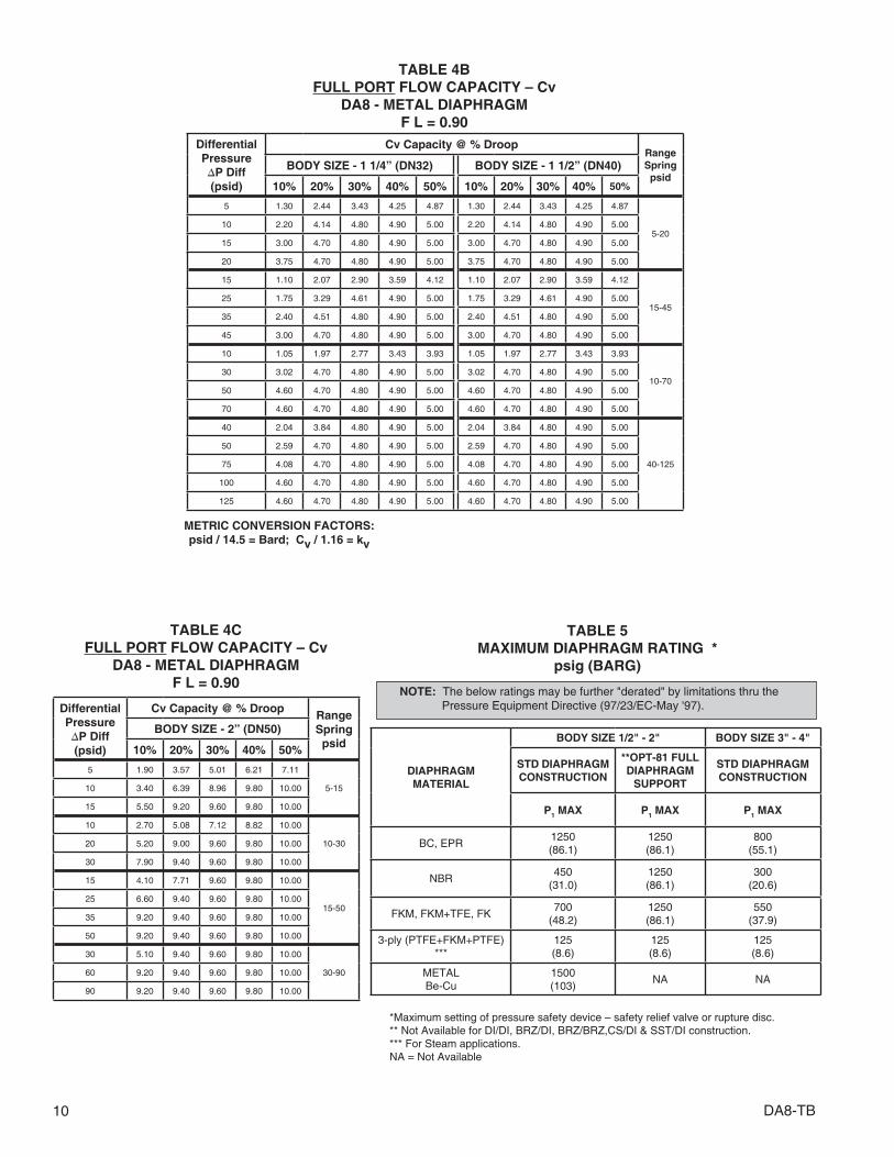
TABLE 4BFULL PORT FLOW CAPACITY – Cv
DA8 - METAL DIAPHRAGMF L = 0.90
TABLE 4CFULL PORT FLOW CAPACITY – Cv
DA8 - METAL DIAPHRAGMF L = 0.90
METRIC CONVERSION FACTORS: psid / 14.5 = Bard; Cv / 1.16 = kv
TABLE 5 MAXIMUM DIAPHRAGM RATING *
psig (BARG)
*Maximum setting of pressure safety device – safety relief valve or rupture disc.** Not Available for DI/DI, BRZ/DI, BRZ/BRZ,CS/DI & SST/DI construction.*** For Steam applications.NA = Not Available
NOTE: The below ratings may be further "derated" by limitations thru the Pressure Equipment Directive (97/23/EC-May '97).
DIAPHRAGMMATERIAL
BODY SIZE 1/2" - 2" BODY SIZE 3" - 4"
STD DIAPHRAGM CONSTRUCTION
**OPT-81 FULL DIAPHRAGM
SUPPORT
STD DIAPHRAGM CONSTRUCTION
P1 MAX P1 MAX P1 MAX
BC, EPR1250(86.1)
1250(86.1)
800(55.1)
NBR450
(31.0)1250(86.1)
300(20.6)
FKM, FKM+TFE, FK700
(48.2)1250(86.1)
550(37.9)
3-ply (PTFE+FKM+PTFE)***
125(8.6)
125(8.6)
125(8.6)
METALBe-Cu
1500(103)
NA NA
Differential Pressure ∆P Diff (psid)
Cv Capacity @ % DroopRange Spring psid
BODY SIZE - 1 1/4” (DN32) BODY SIZE - 1 1/2” (DN40)
10% 20% 30% 40% 50% 10% 20% 30% 40% 50%
5 1.30 2.44 3.43 4.25 4.87 1.30 2.44 3.43 4.25 4.87
5-2010 2.20 4.14 4.80 4.90 5.00 2.20 4.14 4.80 4.90 5.00
15 3.00 4.70 4.80 4.90 5.00 3.00 4.70 4.80 4.90 5.00
20 3.75 4.70 4.80 4.90 5.00 3.75 4.70 4.80 4.90 5.00
15 1.10 2.07 2.90 3.59 4.12 1.10 2.07 2.90 3.59 4.12
15-4525 1.75 3.29 4.61 4.90 5.00 1.75 3.29 4.61 4.90 5.00
35 2.40 4.51 4.80 4.90 5.00 2.40 4.51 4.80 4.90 5.00
45 3.00 4.70 4.80 4.90 5.00 3.00 4.70 4.80 4.90 5.00
10 1.05 1.97 2.77 3.43 3.93 1.05 1.97 2.77 3.43 3.93
10-7030 3.02 4.70 4.80 4.90 5.00 3.02 4.70 4.80 4.90 5.00
50 4.60 4.70 4.80 4.90 5.00 4.60 4.70 4.80 4.90 5.00
70 4.60 4.70 4.80 4.90 5.00 4.60 4.70 4.80 4.90 5.00
40 2.04 3.84 4.80 4.90 5.00 2.04 3.84 4.80 4.90 5.00
40-125
50 2.59 4.70 4.80 4.90 5.00 2.59 4.70 4.80 4.90 5.00
75 4.08 4.70 4.80 4.90 5.00 4.08 4.70 4.80 4.90 5.00
100 4.60 4.70 4.80 4.90 5.00 4.60 4.70 4.80 4.90 5.00
125 4.60 4.70 4.80 4.90 5.00 4.60 4.70 4.80 4.90 5.00
Differential Pressure ∆P Diff (psid)
Cv Capacity @ % DroopRange Spring psid
BODY SIZE - 2” (DN50)
10% 20% 30% 40% 50%
5 1.90 3.57 5.01 6.21 7.11
5-1510 3.40 6.39 8.96 9.80 10.00
15 5.50 9.20 9.60 9.80 10.00
10 2.70 5.08 7.12 8.82 10.00
10-3020 5.20 9.00 9.60 9.80 10.00
30 7.90 9.40 9.60 9.80 10.00
15 4.10 7.71 9.60 9.80 10.00
15-5025 6.60 9.40 9.60 9.80 10.00
35 9.20 9.40 9.60 9.80 10.00
50 9.20 9.40 9.60 9.80 10.00
30 5.10 9.40 9.60 9.80 10.00
30-9060 9.20 9.40 9.60 9.80 10.00
90 9.20 9.40 9.60 9.80 10.00

DA8-TB 11
TABLE TITLE PAGE
DAG-1A ......... DI – Press vs Temp vs End Conn Ratings ......................................12 DAG-1B ..........BRZ – Press vs Temp vs End Conn Ratings ..................................13 DAG-1D ............CS – Design Inlet/Outlet - DA8 .....................................................14 DAG-1F............SST – Design Inlet/Outlet - DA8......................................................14 DAG-2 .....................Max Pressure Drop - Comp Seat ............................................15 DAG-3 .....................Max Pressure Drop - Dynamic Seal Design ............................15 DAG-4 .....................Max Pressure Drop - Basic Trim Mat'ls ...................................15 DAG-5 .....................Temperature Limits – Elastomer Mat'ls. ..................................16 DAG-7 .....................Back Pressure Max Capacity - Plug Wide Open .....................17 DAG-10 ...................Inboard Leakage Ratings ........................................................17 DAG-12 ...................Back Press Recommended Velocity Limits .............................17 DAG-14 ...................Recommended Internal Materials - Liquids .............................18 DAG-14 ...................Recommended Internal Materials - Gases ..............................18 DAG-14 ...................Supplement - Chemical Resistance ........................................19
FIGURE TITLE PAGE
DAG-F1 ...................Dynamic/Static Seals ..............................................................20 DAG-F2 ...................Location of Body/Spring Chamber Taps .................................21
DAG TECHNICAL APPENDIX INDEX

12 DA8-TB
Material Specifi cations(Body / Topworks)
End Connection – Inlet & Outlet
Temperature °F
Working Pressure – psig
Description(Abbr.)
ASTMNo.
End Connection – Pressure Class
NPT 125# FF 250# RF
DI/DI(Note 1)
A395/A395
-20° to +150° 400 200 500
200° 370 190 460
225° 355 180 440
250° 340 175 415
300° 310 165 375
350° 300 150 335
400° 250 140 290
406° 250 140 290
400 WOG, 250 S 225 WOG, 125 S 400 WOG, 250 S
Temperature °C
Working Pressure – Barg
End Connection – Pressure Class
NPT 125# FF 250# RF
-29° to +65° 27.6 13.8 34 .5
107 24.5 12.5 30.2
120° 23.4 12.1 28.7
150° 21.2 11.2 25.7
177° 19.2 10.6 23.8
204° 17.5 9.6 20.3
TABLE DAG-1ADI – DUCTILE IRON
BODY / TOPWORKS MATERIAL SPECIFICATIONSDESIGN PRESSURE vs. TEMPERATURE vs. END CONNECTION RATINGS(To ASME B16.1 for Flanged and B16.4 for NPT Connections per Cast Iron Rating)
NOTE 1: Whenever body and topworks materials are mixed, the P vs. T ratings that should be applied are those which are lowest of the two materials.
Example: CS body, DI topworks; NPT end connections, 200°F temperature. Because the topworks is not “end fl anged”, use the DI limits of "400 PSIG CWP 370/200F" from above to com-
pare to CS limits from DAG-1C values. The DI limits are lower, so ratings from DAG-1A MUST be used as the limits.
NOTE 2: Unless stated otherwise, design pressure is Maximum Allowable Working Pressure (MAWP) for Inlet and Outlet.

DA8-TB 13
Material Specifi cations(Body / Topworks)
End Connection – Inlet & Outlet (Note 2)
Description (Abbr.) ASTM No. Temperature °F
Working Pressure –psig
End Connection – Pressure Class
NPT 150# FF 300# FF
BRZ/BRZ(Note 1)
B62,Alloy C83600/B62,
Alloy C83600
-325° to +150° * 500 225 500
175° 390 220 480
200° 385 210 465
225° 375 205 445
250° 365 195 425
300° 335 180 390
350° 300 165 350
400° 250 150 315
406° 250 150 315
Temperature °C
Working Pressure – Barg
End Connection – Pressure Class
NPT 150# FF 300# FF
-198° to +65° * 34.5 15.5 34.5
107° 25.8 14.0 30.8
120° 25.1 13.5 29.5
150° 23.0 12.4 26.8
177° 20.4 11.3 24.0
204° 17.8 10.3 21.4
TABLE DAG-1BBRZ – BRONZE
BODY / TOPWORKS MATERIAL SPECIFICATIONS
DESIGN PRESSURE vs. TEMPERATURE vs. END CONNECTION RATINGS(Per ASME B16.24 for Flanged and B16.15 for NPT Connections)
NOTE 1: Whenever body and topworks materials are mixed, the P vs. T ratings that should be applied are those which are lowest of the two materials.
Example: BRZ body, DI topworks; NPT end connections, ambient temperature. Because the topworks is not “end fl anged”, use the DI limits of "400 PSIG CWP 370/200F" from DAG-1A to
compare to above DAG-1B values. The DI limits are lower, so ratings from DAG-1A MUST be used as the limits.
NOTE 2: Unless stated otherwise, design pressure is Maximum Allowable Working Pressure (MAWP) for Inlet and Outlet.
* See Minimum Temperature Ratings Table below.
Regulator FunctionMaterial Specifi cations
(Body / Topworks - Connections)Description (Abbr.)
Pressure at Min. Temperature
Back Pressure Relief
BRZ/BRZInlet - 500 psig CWP to -325°F (-198°C)
Outlet - 500 psig CWP to -325°F (-198°C)
SST/SST - NPT, BSP, Ext. Nipples,Tube Ends and 600# Flgs
Inlet - 625 psig CWP to -425°F (-254°C)
Outlet - 625 psig CWP to -425°F (-254°C)
DESIGN PRESSURE RATINGAT MIN. TEMPERATURE
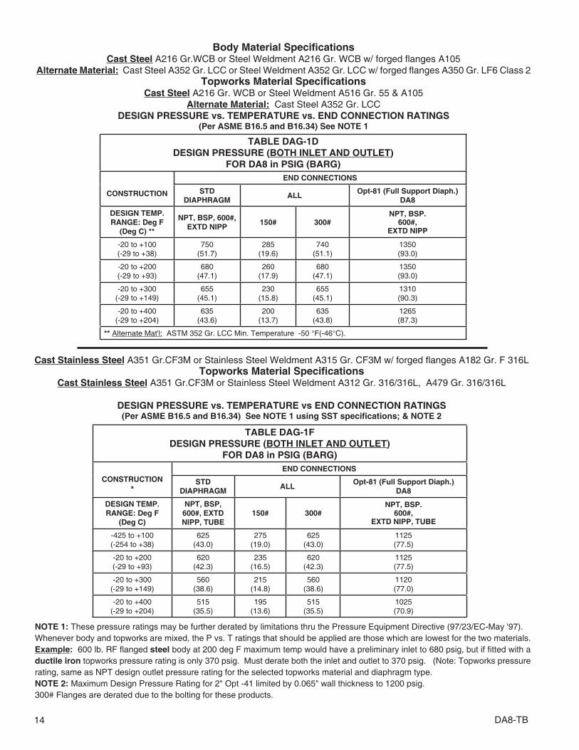
14 DA8-TB
TABLE DAG-1DDESIGN PRESSURE (BOTH INLET AND OUTLET)
FOR DA8 in PSIG (BARG)
CONSTRUCTION
END CONNECTIONS
STDDIAPHRAGM
ALLOpt-81 (Full Support Diaph.)
DA8
DESIGN TEMP. RANGE: Deg F
(Deg C) **
NPT, BSP, 600#,EXTD NIPP
150# 300#NPT, BSP.
600#,EXTD NIPP
-20 to +100(-29 to +38)
750(51.7)
285(19.6)
740(51.1)
1350(93.0)
-20 to +200(-29 to +93)
680(47.1)
260(17.9)
680(47.1)
1350(93.0)
-20 to +300(-29 to +149)
655(45.1)
230(15.8)
655(45.1)
1310(90.3)
-20 to +400(-29 to +204)
635(43.6)
200(13.7)
635(43.8)
1265(87.3)
** Alternate Mat'l: ASTM 352 Gr. LCC Min. Temperature -50 °F(-46°C).
Body Material Specifi cations Cast Steel A216 Gr.WCB or Steel Weldment A216 Gr. WCB w/ forged fl anges A105
Alternate Material: Cast Steel A352 Gr. LCC or Steel Weldment A352 Gr. LCC w/ forged fl anges A350 Gr. LF6 Class 2Topworks Material Specifi cations
Cast Steel A216 Gr. WCB or Steel Weldment A516 Gr. 55 & A105Alternate Material: Cast Steel A352 Gr. LCC
DESIGN PRESSURE vs. TEMPERATURE vs. END CONNECTION RATINGS(Per ASME B16.5 and B16.34) See NOTE 1
NOTE 1: These pressure ratings may be further derated by limitations thru the Pressure Equipment Directive (97/23/EC-May '97).Whenever body and topworks are mixed, the P vs. T ratings that should be applied are those which are lowest for the two materials.Example: 600 lb. RF fl anged steel body at 200 deg F maximum temp would have a preliminary inlet to 680 psig, but if fi tted with a ductile iron topworks pressure rating is only 370 psig. Must derate both the inlet and outlet to 370 psig. (Note: Topworks pressure rating, same as NPT design outlet pressure rating for the selected topworks material and diaphragm type.NOTE 2: Maximum Design Pressure Rating for 2" Opt -41 limited by 0.065" wall thickness to 1200 psig.300# Flanges are derated due to the bolting for these products.
Cast Stainless Steel A351 Gr.CF3M or Stainless Steel Weldment A315 Gr. CF3M w/ forged fl anges A182 Gr. F 316LTopworks Material Specifi cations
Cast Stainless Steel A351 Gr.CF3M or Stainless Steel Weldment A312 Gr. 316/316L, A479 Gr. 316/316L
DESIGN PRESSURE vs. TEMPERATURE vs END CONNECTION RATINGS(Per ASME B16.5 and B16.34) See NOTE 1 using SST specifi cations; & NOTE 2
TABLE DAG-1FDESIGN PRESSURE (BOTH INLET AND OUTLET)
FOR DA8 in PSIG (BARG)
CONSTRUCTION
*
END CONNECTIONS
STDDIAPHRAGM
ALLOpt-81 (Full Support Diaph.)
DA8
DESIGN TEMP. RANGE: Deg F
(Deg C)
NPT, BSP, 600#, EXTD NIPP, TUBE
150# 300#NPT, BSP.
600#,EXTD NIPP, TUBE
-425 to +100(-254 to +38)
625(43.0)
275(19.0)
625(43.0)
1125(77.5)
-20 to +200(-29 to +93)
620(42.3)
235(16.5)
620(42.3)
1125(77.5)
-20 to +300(-29 to +149)
560(38.6)
215(14.8)
560(38.6)
1120(77.0)
-20 to +400(-29 to +204)
515(35.5)
195(13.6)
515(35.5)
1025(70.9)

DA8-TB 15
TABLE DAG-2MAXIMUM PRESSURE DROP FOR
COMPOSITION SEATS
Body SizeMax. Pressure Drop - psid (Bard)
Seat Material
in (DN)POLYALL * GF-TFE
Liquid * Gas Steam Liquid * Gas Steam √
1/2" – 1" (15-25) 600 (41.3) 750 (51.7) DNA 450 (31.0) 1000 (68.9) 150/125 (10.3/8.6)
1-1/4" – 1-1/2"
(32-40) 600 (41.3) 600 (41.3) DNA 450 (31.0) 900 (62.0) 150/125 (10.3/8.6)
2" (50) 600 (41.3) 600 (41.3) DNA 450 (31.0) 750 (51.7) 150/125 (10.3/8.6)
3" – 4" (80-100) 500 (34.4) 600 (41.3) DNA 450 (31.0) 750 (51.7) 125 (8.6)
V-TFE CTFE
1/2" – 1" (15-25) 300 (20.7) 600 (41.3) 125 (8.6) 600 (41.3) 3000 (206.9) DNA
1-1/4" – 1-1/2"
(32-40) 300 (20.7) 600 (41.3) 125 (8.6) 600 (41.3) 3000 (206.9) DNA
2" (50) 300 (20.7) 600 (41.3) 125 (8.6) 600 (41.3) 2000 (137.9) DNA
3" – 4" (80-100) 300 (20.7) 450 (31.0) 125 (8.6) 500 (34.4) 1500 (103.4) DNA
* Only seat material to be applied in liquid “partially cavitating” service is PolyAll.√ Steam Service: metal diaphragm/composition diaphragm.N/A = Not AvailableDNA = Do Not Apply
Body SizeMax. Pressure Drop - psid (Bard)
Dynamic Seal Design
in (DN)"OR" – O-RING * "CP" – TFE CAP "CW" – TFE CAP w/WIPER
Liquid * Gas * Steam Liquid Gas Steam Liquid Gas Steam
1/2" – 1"
(15-25)
600 (41.3) 750 (51.7) DNA 600 (41.3) 600 (41.3) DNA 450 (31.0) 600 (41.3) DNA
1-1/4" –
1-1/2"
(32-40)
600 (41.3) 750 (51.7) DNA 600 (41.3) 600 (41.3) DNA 450 (31.0) 600 (41.3) DNA
2" (50) 600 (41.3) 750 (51.7) DNA 600 (41.3) 600 (41.3) DNA 450 (31.0) 600 (41.3) DNA
3" – 4"
(80-100)
600 (41.3) 750 (51.7) DNA 600 (41.3) 600 (41.3) DNA 450 (31.0) 600 (41.3) DNA
"PR" – PISTON RING ASSY."PW" – PISTON RING ASSY.
w/WIPER"UC" – U-CUP
1/2" – 1"
(15-25)
DNA DNA√
150/125(10.3/8.6) DNA DNA
√ 150/125
(10.3/8.6) 600 (41.3) 3000 (206.9) DNA
1-1/4" –
1-1/2"
(32-40)
DNA DNA√
150/125(10.3/8.6) DNA DNA
√ 150/125
(10.3/8.6) 600 (41.3) 3000 (206.9) DNA
2" (50) DNA DNA√
150/125(10.3/8.6) DNA DNA
√ 150/125
(10.3/8.6) 600 (41.3) 3000 (206.9) DNA
3" – 4"
(80-100)
DNA DNA 125 (8.6) DNA DNA 125 (8.6) 600 (41.3) 3000 (206.9) DNA
* Only seat material to be applied in liquid “partially cavitating” or “fl ashing” service is PolyAll.√ Steam Service: metal diaphragm/composition diaphragm.N/A = Not Available DNA = Do Not Apply wo/ = without w/ = with
TABLE DAG-3MAXIMUM PRESSURE DROP FOR
DYNAMIC SEAL DESIGNS
Body Size Max Pressure Drop - psid (Bard)
Basic Trim Materialin (DN) "P" – 17-4PH SST "S" – 316L SST "M" – Monel "T" – Hybrid *
1/2" – 2" (15-50) 3000 (206.9) 800 (55.1) 1500 (103.4) 3000 (206.9)
3" – 4" (80-100) 3000 (206.9) 800 (55.1) 1500 (103.4) 3000 (206.9)
* 17-4PH SST plug & piston, Monel cage.
TABLE DAG-4MAXIMUM PRESSURE DROP FOR
BASIC TRIM MATERIAL

16 DA8-TB
Elastomer T Maximum T MinimumS
eats
ID Description °F (°C) °F (°C)PolyAll Proprietary Polyurethane Derivative 225° (107°) -60° (-51°)
GF-TFE Glass-fi lled Polytetrafl uorethylene 425° (218°) -325° (-198°)
V-TFE Virgin TFE 400° (205°) -325° (-198°)
CTFE Chlorotrifl uoroethylene TFE 300° (148°) -325° (-198°)
FKM Fluorocarbon Elastomer 400° (205°) 0° (-17°)
Di a
ph
rag
ms
3-Ply 3-Ply TFE/FKM/TFE 400° (205°) 0° (-17°)
BC Neoprene (Polychloroprene) 250° (121°) -65° (-53°)
EPR Ethylene Propylene 300° (148°) -40° (-40°)
FK Fluorosilicone 350° (177°) -65° (-54°)
FKM Fluorocarbon Elastomer 400° (205°) 0° (-17°)
NBR Buna-N (Nitrile) 250° (121°) -70° (-56°)
FKM+TFE Fluorocarbon Elastomer + TFE 400° (205°) 0° (-17°)
Sta
tic
Sea
ls
RTFE Bronze-fi lled TFE 425° (218°) 70° (21°)
V-TFE Virgin TFE 400° (205°) -325° (-198°)
EPR Ethylene Propylene 300° (148°) -40° (-40°)
FK Fluorosilicone 350° (177°) -65° (-54°)
FKM Fluorocarbon Elastomer 400° (205°) -20° (-28°)
NBR Buna-N 212° (100°) -40° (-40°)
SST/TFE 301/302 SST U-cup / TFE 400° (205°) -325° (-198°)
HC/TFE Hastelloy C U-cup / TFE 400° (205°) -325° (-198°)
Dyn
amic
Sea
ls
"PR" Piston Ring Assy, GF-TFE / SST 425° (218°) -40° (-40°)
"PW" PRA* w/Wiper, GF-TFE / SST / GF-TFE 425° (218°) 70° (21°)
"CW" – EPR/TFE TFE Cap Seal, EPR O-ring, GF-TFE Wiper 300° (148°) -40° (-40°)
"CW" – NBR/TFE TFE Cap Seal, NBR O-ring, GF-TFE Wiper 212° (100°) -40° (-40°)
"CW" – FK/TFE TFE Cap Seal, FK O-ring, GF-TFE Wiper 350° (177°) -40° (-40°)
"CW" – FKM/TFE TFE Cap Seal, FKM O-ring, GF-TFE Wiper 400° (205°) -20° (-28°)
"CP" – EPR/TFE TFE Cap Seal, EPR O-ring 300° (148°) -40° (-40°)
"CP" – NBR/TFE TFE Cap Seal, NBR O-ring 212° (100°) -40° (-40°)
"CP" – FK/TFE TFE Cap Seal, FK O-ring 350° (177°) -10° (-23°)
"CP" – FKM/TFE TFE Cap Seal, FKM O-ring 400° (205°) -20° (-28°)
SST/TFE 301/302 SST U-cup / TFE 400° (205°) -325° (-198°)
HC/TFE Hastelloy C U-cup / TFE 400° (205°) -325° (-198°)
ELG/TFE Elgiloy / TFE U-cup 400° (205°) -325° (-198°)
* PRA - Piston Ring Assembly
TABLE DAG-5TEMPERATURE LIMITS
FOR ELASTOMERIC MATERIALS
ABBREVIATIONS
FK = Fluorosilicone NBR = Buna-N PTFE = Polytetrafl uoroethylene PRA = GF-TFE/SST
FKM = Fluorocarbon Elastomer RTFE = Brz-fi ll TFE V-TFE = Virgin TFE BC = Neoprene
EPR = Ethylene Propylene GF-TFE = Glass-fi ll TFE CTFE = Chlorotrifl uoroethylene TFE ELG = Elgiloy
Metal Diaphragm T Maximum T MinimumID Description °F (°C) °F (°C)
BE-CU Beryllium Copper 400° (205°) -325° (-198°)

DA8-TB 17
TABLE DAG-7BACK PRESSURE MAXIMUM CAPACITY WITH PLUG WIDE-OPEN
Body Size Full PortMax Capacity
Full PortMax Capacity
in (DN) Cv Kv Cv Kv
1/2" (15) 4.0 2.9 3.0 2.6
3/4" (20) 8.0 5.9 3.0 2.6
1" (25) 12.8 11.0 3.0 2.6
1-1/4" (32) 23 20 5.1 4.4
1-1/2" (40) 26 22 5.1 4.4
2" (50) 51 44 10.2 8.8
3" (80) 120 104
4" (100) 187 161
Diaphragm Composition Metal
NOTE: The above Cv factors may be used for sizing of safety relief valves or rupture discs.
TABLE DAG-10INBOARD LEAKAGE RATINGS *
Per ANSI/FCI 70-2
Seat Material
Dynamic Seal
O-RingDynamic Seals Except
O-Ring
CTFE, GF-TFE, and V-TFE
IV IV
PolyAll, FKM VI IV
*Inboard leak rates are the composite leakage of the seat leakage + dynamic seal leakage, considered as a single inboard leakage value.
ApplicationFluid
Valve UpstreamPipe
Valve BodyDownstream
PipeUnits
TypeSize Range Inlet (1-Phase)
Outletin (DN) Recommend Max. Recommend Max.
LiquidBPV
1/2"–4" (15-100) 5-8 16 15 20See
Notes 1 & 2Below
SeeNotes 3 & 4
BelowFt/Sec6" (150) 7–12 20 15 24
8"–12" (200-300) 9–14 24 – –
GasBPV
1/2"–1"1-1/4"–2"
(15-25)(32-50)
0.150.20
0.300.30
0.150.20
0.250.30
<1.00 <0.8 Mach #2-1/2"–6" (65-150) 0.22 0.30 0.25 0.35
8"–12" (200-300) 0.25 0.30 – –
SteamBPV
1/2"–1"1-1/4"–2"2-1/2"–6"
(15-25)(32-50)(65-150)
0.100.120.15 0.30
0.200.220.25
0.30<0.8 <0.65 Mach #
8"–12" (200-300) 0.20 – –
NOTES: 1. Liquids experiencing no 2-phase fl ow at valve outlet will have same valve body outlet velocity as inlet velocity. 2. Liquids experiencing 2-phase fl ow at valve outlet should have average velocity less than 150-200 ft/sec. 3. Liquids experiencing 2-phase fl ow at outlet pipe should have average velocity less than 20-50 ft/sec. 4. If valve outlet exceeds recommended limits, then can use external sensing to reach maximum limits. 5. On gas service, a pilot operated prv can work with a outlet Mach = 0.75.
TABLE DAG-12BACK PRESSURE RECOMMENDED VELOCITY LIMITS

18 DA8-TB
LIQUIDS
LIQ
UID
S
LIQ
UID
S
L
IQU
IDS
FluidTmax
°FTmin
°FMetalTrim
Industrial Water –Cold
180° 32° P2
Hot 225° 32° PJ
DI, DM225° 32° PJ
250° 32° PL
Seawater 180° -20° MH
Fuel Oils –Diesel, #1,#2‡
180° -40° P6
Bunker C,#3 - #6‡
180° -40° P6
400° 0° PD
Jet Fuel JP3, JP4, JP5, JP6‡ 400° 0° PD
Kerosene‡ 400° 0° PD
Crude Oils –Sweet‡
225° 0° PB
400° 0° PD
Sour‡ 225° 0° CF *
Heat Transfer Oils –Dowtherm, Therminol,
Mobil-Therm, Silvatherm400° 0° PD
Misc. Oils –Lube Oil‡
180° -40° P6
Naptha‡ 400° 0° PD
Turbine Oil‡ 225° 0° PB
Edible Oils –Vegetable Oil‡
180° -30° PH
Animal Fats‡ 180° -30° PH
Seed Oils‡ 180° -30° PH
Inorganic Acids –Acetic - 5%
100° 0° SL
Acetic - 30% 100° 0° SL
Sulfuric - conc. 100° 0° CF *
Sulfuric - dilute 100° 0° CF *
Nitric - conc. 140° 0° SL
Nitric - dilute 140° 0° SL
Hydrofl uoric(air free) -
dilute, concentrate100° 0° CF *
Hydrobromic 140° 0° CF *
Phosphoric - dilute, concentrate
150° 0° SL
Misc. Liquids –Gasoline‡
150° -40° P6
Benzene (C6H6)‡ 150° 0° SL
Chlorine (Cl2) 150° 0° ML
Bromine (Br2) 150° 0° CF *
Ammonia (NH3) 140° 0° SL
Hydrogen Peroxide (H2O2) 125° 0° SL
Hydrogen Chloride (HCl) 125° 0° ML
Hydrogen Bromide (HBr) 125° 0° SL
Cane Sugar Liquor 180° 0° PH
‡ In accordance with ASME B31.3 "Process Piping", do not use Ductile Iron Body for hydrocarbon or flammable service with inlet pressures greater than 150 psig (10.3 Barg) or temperatures greater than 300 deg F (149 deg C).* CF = Consult Factory
TABLE DAG-14RECOMMENDED INTERNAL MATERIALS
For Pmax, Reference Individual Technical Bulletins
GASES
Atm
osp
her
ic G
ases
FluidTmax
°FTmin
°FTrim
Atmospheric Gases – O2 (GOX)
225° -60° M7
350° -65° M9
350° -325° TN
N2 (GN2),Air, Argon
180° -60° P2
350° -65° P8
CO2 (dry) 180° -40° P6
CO2 (wet) 180° -40° P6
Pro
cess
Gas
es
Process Gases –Nat. Gas (Sweet)
180° -65° P9
Nat. Gas (Sour) 180° -40° CF *
LPG (propane) 180° -40° PH
Ammonia 120° -40° CF *
Hydrogen 180° -325° SN
Helium 180° -325° SN
Chlorine (dry) 200° 0° ME
Hydrogen Chloride (dry) 120° -40° SJ
Hydrogen Bromide (dry) 120° 0° PE
Hydrogen Fluoride (dry) 120° 0° PE
Hydrogen Sulfi de (dry) 140° 0° CF *
Hydrogen Sulfi de (wet) 140° 0° CF *
Sulfur Dioxide (dry) 120° 0° PE
ST
EA
M
P1≤ 125 psig 350° — PG

DA8-TB 19
General Statement: Statements located within this tech ni cal bulletin concerning suitability of fluids with TFE ma te ri als are general statements, and should not be construed as rec om men da tions. Any statements of suita bil ity are the result of a com pi la tion of various sources of information based on experience, tests, and published technical literature. No guarantee or warranty is in anyway implied for a given particular service or application.Additional Reference: For an inclusive listing cov er ing a broad er range of service application fluids, reference “Handbook of Corrosion Resistant Piping”, P.A. Schweitzer, Industrial Press or “Compass Corrosion Guide”, 2nd Edition, K.M. Pruett, Compass Publications. This pub li ca tion will include in for ma tion based on the fol low ing fluid variables:
1. Solution concentration 2. Pressure 3. Temperature
DAG-14 SUPPLEMENTCHEMICAL RESISTANCE

20 DA8-TB
O-RING DYNAMIC SEAL TFE CAP DYNAMIC SEAL TFE CAP DYNAMIC SEAL + WIPER
PRA DYNAMIC SEAL
PRA DYNAMIC SEAL + WIPER
U-CUPDYNAMIC SEAL

DA8-TB 21
Location Description Opt. No. NPT - Size Sp. Ch. Mat'l.
7 Spring Ch. – Inlet Side STD 1/4" ALL
7 & 8
Double Spring Ch. 65A 1/4" ALL
Double Spring Ch. 65B 1/2"
CS ONLYDouble Spring Ch. 65C 3/4"
Double Spring Ch. 65D 1"
FIGURE DAG-F2Location of BODY / SPRING CHAMBER TAPS
Location Description Opt. No. NPT - Size Body Mat'l.
1 & 2 Inlet & Outlet – Right STD 1/4" DI, CS & SST
1, 2 & 3 Inlet & Outlet – Right STD 1/4" BRZ
5 External Sensing – Right STD 1/4" ALL
1, 2,3 & 4
Inlet & Outlet – RightInlet & Outlet – Left
85 1/4" ALL
5 & 6 Double External Sensing 85 1/4" ALL
Body
Flow To Open Direction

22 DA8-TB
ENGLISH UNITS (in) (lbs) METRIC UNITS (mm) (kg)
DIMEN.END
CONN.BODYMAT'L
BODY SIZE
1/2", 3/4
& 1"
1-1/4" &
1-1/2"2" 3" 4"
A NPTDI, BRZ 6.00 9.88 9.88 – –
CS, SST 8.25 9.88 9.75 – –
B
125# FF DI – – – 11.75 13.88
250# RF DI – – – 12.50 14.50
150# FF BRZ ** 9.63 11.50 √ 11.50 11.75 13.88
300# FF BRZ ** 9.63 11.50 √ 11.50 12.15 14.50
150# RF CS, SST 10.75 12.38 √ 10.00 11.75 13.88
150# RF ‡ CS, SST 14.00 14.00 √ 14.00 – –
300# RF CS, SST 10.75 12.38 √ 10.50 12.15 14.50
300# RF ‡ CS, SST 14.00 14.00 √ 14.00 – –
600# RF CS, SST 10.75 12.38 √ 11.25 13.25 15.50
600# RF ‡ CS, SST 14.00 14.00 √ 14.00 – –
C
OPT-32EXT NIPS
CS, SST 14.00 15.75 15.75 – –
OPT-41 SST 11.00 15.25 15.50 – –
E ALL ALL 2.84 3.69 4.00 5.75 7.00
G ALL ALL 6.00 7.00 8.00 11.00 11.13
HALL BRZ/DI † 5.00 5.44 5.80 8.50 8.50
ALL CS/SST † 6.10 6.36 6.91 10.50 10.50
J ALL ALL 10.13 12.63 13.00 23.00 23.50
WEIGHT
wo/ Flanges
ALL 23 33 39 – –
w/Flanges ALL 28 43 52 175 190
END CONN.
BODYMAT'L
BODY SIZE
DN15, DN20
& DN25
DN32 &
DN40DN50 DN80 DN100
NPTDI, BRZ 152 251 251 – –
CS, SST 209 251 248 – –
125# FF DI – – – 298 352
250# RF DI – – – 318 368
150# FF BRZ ** 246 292 √ 292 298 352
300# FF BRZ ** 246 292 √ 292 309 368
150# RF CS, SST 273 314 √ 254 298 352
150# RF ‡ CS, SST 356 356 √ 356 – –
300# RF CS, SST 273 314 √ 267 309 368
300# RF ‡ CS, SST 356 356 √ 356 – –
600# RF CS, SST 273 314 √ 286 336 394
600# RF ‡ CS, SST 356 356 √ 356 – –
OPT-32EXT NIPS
CS, SST 356 400 400 – –
OPT-41 SST 279 387 394 – –
ALL ALL 72 94 102 146 178
ALL ALL 152 178 203 279 283
ALL BRZ/DI † 127 138 147 216 216
ALL CS/SST † 155 161 175 267 267
ALL ALL 257 321 330 584 597
wo/ Flanges
ALL 11 16 18 – –
w/Flanges ALL 13 20 24 79 86
** Flanged BRZ bodies available in sizes 1", 1-1/2", 2", 3", & 4" ONLY.† Spring Chamber material.√ Flange Connections not available for 1-1/4" body size.‡ Opt-34: Special 14" F to F Flange dimensions, CS and SST body material only.Consult Factory for dimensions of ISO DIN Flanged units. (PN16, PN25, PN40)
DIMENSION and WEIGHTS

DA8-TB 23
NOTES
The contents of this publication are presented for informational purposes only, and while every effort has been made to ensure their accuracy, they are not to be con-strued as warranties or guarantees, express or implied, regarding the products or services described herein or their use or applicability. We reserve the right to modify or improve the designs or specifi cations of such product at any time without notice.Cashco, Inc. does not assume responsibility for the selection, use or maintenance of any product. Responsibility for proper selection, use and maintenance of any Cashco, Inc. product remains solely with the purchaser.

24 DA8-TB
MODEL DA8 PRODUCT CODER 03/14/16
E0DPOSITION 3
SIZES & DIAPHRAGM CONSTRUCTION
Body SizeDiaphragm
Support
in (DN)STD OPT-81
CODE CODE1/2" (15) 4 J3/4" (20) 5 K1" (25) 6 L
1-1/4" (32) 7 M1-1/2" (40) 8 N
2" (50) 9 P3" ^ (80) B NA4" ^ (100) C NA
^ Not available with metal diaphragms.NA Not Available
POSITION 14 - SPRING CHAMBER OPTIONS
Description Option CODEStd Flow-thru connections 1/4" -64A F
Flow-thru Spring Chamber, 1/2" NPT CS Material ONLY. -65B GFlow-thru Spring Chamber, 3/4" NPT CS Material ONLY. -65C HFlow-thru Spring Chamber, 1" NPT CS Material ONLY. -65D K
POSITION 15 - BODY OPTIONS
Description Option CODENo Option – 0
Second "SET"of 1/4" (DN8) FNPT Pressure Taps & Plugs. -85 T
POSITION 16 - CERTIFICATE OPTIONS
Description Option CODENo Option – 0
SPECIAL CLEANING: Per Cashco Spec #S-1134. W/ properly selected mat'ls. Suitable for Oxygen Service.
BRZ or SST body material.-55 M
SPECIAL CLEANING: Per Cashco Spec.#S-1542. -56 N
SPECIAL CLEANING: Per Cashco Spec #S-1589 Cl2 Service. -57 P
POSITION 17 - PAINT OPTIONS
Description Option CODENo Option – 0
Epoxy Painted Per Cashco Spec #S-1547. -95 WEpoxy Painted Per Cashco Spec #S-1687 OFFSHORE Applic. -95OS Y
POSITION 11 - RANGE SPRINGS
BodySize
Pressure RangeCODE
BodySize
Pressure RangeCODE
psid bard psid bard
1/2"3/4"1"
(DN15,20
& 25)
1-5 ^ .07-.34 1
2"(DN50)
1-5 ^ .07-.34 11-10 * .07-.68 S 1-10 * .07-.68 S5-20 .34-1.3 A 5-15 .34-1.0 M10-35 .68-2.4 B 10-30 .68-2.0 N20-80 1.3-5.5 C 15-50 1.0-3.4 P
30-150 2.0-10.3 D 30-90 2.0-6.2 Q70-200 4.8-13.7 E
3" & 4"(DN80 &
100)
1-10 .07-.68 S
1-1/4"1-1/2"(DN3& 40)
1-5 ^ .07-.34 1 5-20 .34-1.3 A1-10 * .07-.68 S 10-40 .68-2.7 T5-20 .34-1.3 A 10-70 .68-4.8 J
15-45 1.0-3.1 H 40-125 2.7-8.6 K10-70 .68-4.8 J ^ Composition diaphragm construction ONLY
* Metal Diaphragm for Psp ≥ 5 psid. (.34Bard)40-175 2.7-12.0 2
POSITION 6 & 7 - DIAPHRAGM AND SEAT MATERIALS
Trim MaterialO-ring/Seal
CODESeat Diaphragm Static Dynamic
17-4PH SST"P"
PA BC NBR SST/TFE u-cup P2CTFE BC NBR SST/TFE u-cup P3
PA NBR NBR SST/TFE u-cup P6 PA FK FK SST/TFE u-cup P7 ‡
GF-TFE FK FK SST/TFE u-cup P8 ‡V-TFE FK FK SST/TFE u-cup P9 ‡
PA FKM FKM SST/TFE u-cup PBGF-TFE FKM FKM SST/TFE u-cup PDV-TFE FKM + TFE SST/TFE u-cup SST/TFE u-cup √ PE
GF-TFE 3-ply RTFE SST/TFE u-cup $ PFGF-TFE 3-ply RTFE PRA $ PG
PA NBR NBR TFE+NBR CP PHPA EPR EPR TFE+EPR CP PJPA FK FK TFE+FK CP PK
GF-TFE FKM FKM TFE+FKM CP PLFKM FKM FKM SST/TFE u-cup PZ
Monel"M"
PA FK FK SST/TFE u-cup ‡‡ M7 ‡V-TFE FK FK SST/TFE u-cup M9 ‡V-TFE FKM-TFE SST/TFE u-cup SST/TFE u-cup √ ME
PA NBR NBR TFE+NBR CP MHPA EPR EPR TFE+EPR CP MJPA FK FK TFE+FK CP MK
GF-TFE FKM FKM TFE+FKM CP MLFKM FKM FKM SST/TFE u-cup MZ
316L SST"S"
PA FK FK SST/TFE u-cup S7 ‡V-TFE FK FK SST/TFE u-cup S9 ‡
PA BE-CU * SST/TFE u-cup SST/TFE u-cup SMV-TFE BE-CU * SST/TFE u-cup SST/TFE u-cup SN
PA NBR NBR TFE+NBR CP SHPA EPR EPR TFE+EPR CP SJPA FK FK TFE+FK CP SK
GF-TFE FKM FKM TFE+FKM CP SL
17-4PH/Monel/17-4PH
"T"
PA FK FK SST/TFE u-cup ‡‡ T7 ‡V-TFE FK FK SST/TFE u-cup T9 ‡
PA BE-CU * SST/TFE u-cup SST/TFE u-cup TMV-TFE BE-CU * SST/TFE u-cup SST/TFE u-cup TN
PA NBR NBR TFE+NBR CP THPA EPR EPR TFE+EPR CP TJPA FK FK TFE+FK CP TK
GF-TFE FKM FKM TFE+FKM CP TL
* 3" - 4" sizes are not available with metal diaphragm.
‡ For Low Ambient Temperatures (See DAG for Min. Temperatures)‡‡ For GOX service, PA seats allowed in BRZ Bodies only.√ Sizes 3"-4" use V-TFE static seal.$ For Steam applications Max Press < 125 psig. Abbreviations defined on page 2
8POSITION 5
BODY & SPRING CHAMBER MATERIALS
Materials CODE Materials CODEDI/DI 1 LCC/LCC * / ** 6
BRZ/DI 2 LCC/SST * 8BRZ/BRZ ‡‡ B SST/DI 7
CS/DI 4 SST/CS * √ 9CS/CS * √ 5 SST/SST * A
* For Opt-81 Select CS , LCC or SST Spring
Chamber Material except in Canada, use SST.
See Table 1. NOTE: (CS Spg Chmb Mat'l in
Sizes 3"-4" not registered for shipment into
Canada.)
**LCC Mat'l not available in 3" - 4".
‡‡ Sizes 1/2" - 2"
POSITION 8 - Product Classifi cationUnder European"Pressure Equipment Directive"
PRODUCT DESTINATION HAZARD CATEGORY CODE
Anywhere except Europe N/A 7
EuropeanCountries * (CE Mark does not apply
to DN25 and below)
Sound Engineering Practice (SEP)
S
CE Marked Hazard Cat I or II E
* For products to be placed in service in Europe - Ref to Directive 97/23/EC. Forward Completed "EU" Application Recorder prior to quotation. (Without Recorder- Processing of Purchase Order will be delayed). Contact Cashco for Assistance.
POSITION 10 - END CONNECTIONS / ASME
Size Material Method End Conn CODE End Conn CODE End
Conn CODE
1/2" - 2" ALL – NPT 1 – – – –2-1/2" - 4" DI Integral 125#FF 2 250#RF 3 – –
1", 1-1/2" - 4" BRZ Integral 150#FF 6 300#FF 7 – –1/2" - 3/4" CS,SST Opt-30
150#RF 4 300#RF 5 600# RF** 8
1" - 4" CS-SST Integral *1/2" - 2" ALL Opt-31 BSP P – – – –1/2" - 2" CS, SST Opt-32 Extended Nipples E
1/2" - 2" (14" F to F) CS, SST Opt-34 * 150#RF V 300#RF W 600#RF Y1/2" - 1", 1-1/2" - 2 SST Opt-41 Non-High Purity Tube Ends T – –
END CONNECTIONS FOR ISO DIN FLANGESDN15-25, 40, 50
BRZ IntegralPN40 FF - will mate with PN16, 25 and 40 J
DN65-100 PN16 FF K PN25 FF L PN40 FF M
DN15-25, 40, 50 CS, SST Opt-30 PN40 RF - will mate with PN16, 25 and 40 DDN80-100 CS, SST Integral PN16 RF A PN25 RF C PN40 RF G
* Flanges Not Available for 1-1/4" (DN32) size.** 1" size w/ 600# RF CS,or SST has weld-on fl anges Opt-30.
POSITION 12 - SENSING FLOW DIRECTION
OptionFlow To Open
CODEInternal 1External 2
Large Internal 4
For Special ConstructionContact Cashco for Special Code
X
An “X” in POS 12 followed by a 5-digit control num ber over rides remaining selections.
POS3
POS8
POS5
POS10
POS11
POS12
POS14
POS15
POS16
POS17
POS6 & 7

Cashco, Inc.P.O. Box 6 Ellsworth, KS 67439-0006PH (785) 472-4461Fax. # (785) 472-3539www.cashco.comemail: [email protected] in U.S.A. DA8-TB
Cashco do Brasil, Ltda.Al.Venus, 340Indaiatuba - Sao Paulo, BrazilPH +55 11 99677 7177Fax. No. www.cashco.comemail: [email protected]
Cashco GmbHHandwerkerstrasse 1515366 Hoppegarten, GermanyPH +49 3342 30968 0Fax. No. +49 3342 30968 29www.cashco.comemail: [email protected]