model easy-plus emergency alert system encoder/decoder
TRANSCRIPT

EASy-PLUS® User Manual – 1
TRILITHIC Rev 1.02
Model EASy-PLUS®
Emergency Alert SystemEncoder/Decoder
User’s Manual
P/N 0010224001

EASy-PLUS® User Manual2 –
TRILITHICRev 1.02
Trilithic Incorporated’s latest innovation for your Emergency Alert System is the EASy-PLUS ® Encoder/Decoder. The fully featured E.A.S system, highlighted by the EASy-PLUS ® Encoder/Decoder was designed with thesmallest of cable systems in mind, and can handle a system serving 100 subscribers as well as systems handling over2,000,000 subscribers. With Trilithic’s embedded DSP technology and manufacturing, standard features such asFLASH BIOS will guarantee that your EASy-PLUS ® platform will never go out of style. Periodic updates to theplatform are handled with the ease of a simple download from our WEB site. No more disassembly just to changeproms or software. With Trilithic’s EASy-NET® option, a simple phone call from your desktop PC to any one ofyour remote headends, allows you to retrieve the last 100 E.A.S. events from nonvolatile memory for logging andprinting at your office. You’ll never miss your FCC required logging because of printer failures, paper jams or lackof paper. Innovations such as built-in AM/FM/NOAA selectable tuners, automatically generated and programmableFCC weekly testing, remote hub-site transmitter, and complete Motorola® digital platform compliance, truly makesthis your Emergency Alert System of choice.
The EASy-PLUS ® has the following standard and built-in, features and benefits:
§ EASy-PLUS ® enables parsing of F.I.P.S. codesThe new Trilithic EASy-PLUS ® encoder/decoder distributes individual analog E.A.S. messages structuredfor, or earmarked for, one specific community or up to sixteen (16) communities located within multi-trunkoutput headends.
§ Flash BIOSTrilithic’s new EASy-PLUS ® encoder/decoder eliminates the need to remove the unit from the rack, pull thecover or lid and change or upgrade chipsets and proms. Government-regulation modifications or changes,new programming, additional advancements, and many other new features, can easily be handled through asimple upload via the WEB.
§ Programmable RWT (Required Weekly Test) for Automatic TriggeringThis feature allows your E.A.S. system to automatically generate a random RWT event, once, within eachseven (7) day window, satisfying the FCC requirement for cable systems generating and logging their ownweekly test.
§ Stores the most recent 100 emergency alertsA nonvolatile Emergency Alert Storage System eliminates the need for attaching a printer at the headends’encoder/decoder to view the most current alerts or events. A continuous update of the last 100 E.A.S.events triggered through Trilithic’s EASy-PLUS ® encoder/decoder can be downloaded via a PC at theheadend, or through the optional EASy-NET® telephone interface anywhere in the country.E.A.S. events can easily be archived and/or printed on an external dot-matrix printer at the customer’sconvenience.Logfile is word-processor compatible.
§ Two (2) internal radios that are each tunable as AM, FM, or NOAA radiosThis means you will not have to purchase any additional radios to meet the FCC requirement of LP-1 andLP-2 monitoring stations. Simply tune each of the two radio receivers to either AM or FM, to match thedesignated LP-1 and LP-2 stations assigned for your area, or the NOAA frequencies if so needed.Dual cards can be installed giving four (4) internal radio selections.
§ Four (4) external radio inputs for added monitoring capabilitiesThis feature allows you to meet the requirements dictated by some State Emergency Management Plans thatmay require a possible third, fourth or more monitoring selections.
§ Remote hub-site insertion transmitter is included as standard equipmentAn internal AFSK TX transmitter is included as standard equipment in the new EASy-PLUS ® encoder/decoder. This transmitter eliminates all external remote TX components of earlier E.A.S. systems.

EASy-PLUS® User Manual – 3
TRILITHIC Rev 1.02
The AFSK TX transmitter is self-contained, and includes audio switching capabilities for “tune-to” audiodistribution and remote hub-site support via Trilithic’s Virtual Controller.
§ Three (3) Programmable dry-contact-closure relaysThese programmable relays can be conveniently used for directly driving comb generators, Motorola® OM-1000(s) for digital E.A.S., and multi-vendors distribution switches.
§ Audio D/A outputsFour (4) outputs are included on the EASy-PLUS ® encoder/decoder allowing for simple audio distributionutilizing all technologies of switching.
§ Latest DSP TechnologyTrilithic’s use of Digital Signal Processing provides the most current engineering and manufacturingprocesses available.
§ EASy-Plus Setup ProgramThe simple, user-friendly setup program walks you through the entire system setup easily, upon initializa-tion. No guess work involved.
§ EASy-Plus Standard FeaturesThe EASy-PLUS ® encoder/decoder has a built-in Character Generator, a Microphone for generating yourown messages, front-panel Speaker, TTL control lines, front panel Keypad entry, and an Audio DistributionAmplifier.
§ Trilithic, Inc. is an ISO-9001 Certified company.
§ Trilithic, Inc., has a dedicated Marketing, Sales and Engineering in Indiana, New York and NorthCarolina committed solely to YOUR current E.A.S. needs and your future E.A.S. support.

EASy-PLUS® User Manual4 –
TRILITHICRev 1.02
CONTENTS
SECTION 1GENERAL INFORMATION..................................................................................................................................................61.1 Introduction1.2 Specifications1.3 FCC Certification 71.4 Warranty 81.5 Claims for Damage in Shipment1.6 Technical Support
SECTION 2UNDERSTANDING THE EASy-PLUS® SYSTEM.................................................................................................................92.1 Introduction2.2 Unpacking and Inspection2.3 Front Panel2.4 Back Panel 102.5 Terminal Connections
SECTION 3PRE-INSTALLATION SYSTEM CHECK...............................................................................................................................113.1 Initial Power Application3.2 Self-Testing the Encoder/Decoder3.3 Testing the Parallel Printer Port3.4 Testing the Digital Voice Recorder3.5 Testing the Internal Character Generator
SECTION 4BASIC PROGRAMMING OF THE EASy-PLUS ENCODER/DECODER...............................................................................124.1 Introduction4.2 Accessing Front Panel Setup Menu4.3 Front Panel Menu Items
SECTION 5ADVANCED PROGRAMING OF THE EASy-PLUS ENCODER/DECODER..........................................................................135.1 Introduction5.2 Loading Setup Program onto your PC or Laptop5.3 EASy-PLUS Software Setup Program
SystemCountiesEventsEncoderEAS LogsAudio InAudio CFGCGsHubsI/O CFG
SECTION 6EASY-PLUS® ENCODER/DECODER INSTALLATION AND WIRING...................................................................................206.1 Introduction Single (Composite) I.F. Replacement6.2 Selecting a “Designated E.A.S. Channel” at I.F.6.3 LS-16P Lossless Splitter Placement and Connection6.4 Auxiliary I.F. Switch Installation (SW-4)6.5 Single (Composite) I.F. Source Modulator Installation (IFS-3)6.6 Precision I.F. Level Alignment of the LS-16P Lossless Splitter6.7 Procedure for precision I.F. Alignment
SECTION 7I.F. (COMPOSITE I.F., AUX. I.F., SINGLE I.F.) INTERFACE AND INSTALLATION...............................................................227.1 Introduction Single (Composite) I.F. Replacement7.2 Selecting a “Designated E.A.S. Channel” at I.F.7.3 LS-16P Lossless Splitter Placement and Connection7.4 Auxiliary I.F. Switch Installation (SW-4)7.5 Single (Composite) I.F. Source Modulator Installation (IFS-3)

EASy-PLUS® User Manual – 5
TRILITHIC Rev 1.02
7.6 Precision I.F. Level Alignment of the LS-16P Lossless Splitter7.7 Procedure for precision I.F. Alignment
SECTION 8COMB GENERATOR INTERFACE and INSTALLATION.....................................................................................................288.1 Introduction8.2 S8.3 L8.4 A8.5 S8.6 P8.7

EASy-PLUS® User Manual6 –
TRILITHICRev 1.02
SECTION 1
GENERAL INFORMATION
1.1 INTRODUCTIONThe EASy-PLUS® encoder/decoder is a third generation product from Trilithic, Inc. The encoder/decoder is a fully self-contained system, which includes a NTSC video character generator output, multiple balanced audio outputs, audio andvideo switching, 100 message queue, speaker and microphone, two internal AM/FM/NOAA radios and four program-mable contact closures used for such things as OM-1000 digital switching.
The EASy-PLUS® E.A.S. Encoder/Decoder is a two-U rack mounted control center capable of performing manual or auto-mated EAS messaging for cable Headends and Hub sites, in accordance with CFR 47 part 11 FCC regulations, and theEAS Cable Handbook.
The EASy-PLUS® receives E.A.S. messages from up to six audio sources (internal or external), decodes the message, andoperates Cable System equipment to replay the message for subscribers. In addition, messages can be originated by theuser via local or remote control of the EASy-PLUS®. The E.A.S. audio sources for the EASy-PLUS® include internal AM/FM/NOAA radios and external audio inputs that can be connected to any known E.A.S. audio source. E.A.S. audio isdecoded by the internal AFSK circuitry, sorted, and then interpreted to determine the type of emergency or test. Thelocations codes for which the emergency applies, and other information supplied in the E.A.S. header are also decoded. Ifa voice message is contained in the E.A.S. message, it is recorded for playback to subscribers. E.A.S. messages thenpass through a series of tests to determine if the message matches predefined, user configurable filters and parameters foryour location. E.A.S. activation of the cable system then automatically occurs. To play an E.A.S. message to your subscrib-ers, the EASy-PLUS® activates TTL drivers and Contact Closures, as well as sending commands via RS-485 and HighData Rate AFSK. The EASy-PLUS® also supplies pertinent video and re-encodes and plays the E.A.S. FSK header andrecorded audio. The TTL drivers, Contact Closures, and RS-485 commands activate your interface equipment (i.e. I.F.switching, comb generator, baseband character generators) throughout the headend to provide the emergency audio andvideo to all channels of the cable system. In addition to the E.A.S. messaging capabilities, the EASy-PLUS® logs allreceived and transmitted messages to a printer, the LCD display, and it’s internal log storage area.
The EASy-PLUS® has an optional dial-in telephone interface and a unique remote feature using EASy-NET® optionalsoftware for remote control of the entire system. Using the EASy-NET® software, the operator can generate any eventcode and header by simply clicking on the list of events. Prerecorded, or live audio can also be added to the event.
FLASH-BIOS is used to update the EASy-PLUS® nonvolatile memory, programming, and FCC event codes list.
The EASy-PLUS® encoder/decoder has the ability to parse FIPS codes out to individual counties or areas in conjunctionwith the appropriate wiring architecture of the cable headend. This keeps the interruptions to a minimum for customersnot affected by the alerted area.
Trilithic’s unique AFSK transmitter card comes standard in the system. The AFSK signal alerts Trilithic’s downstreamVirtual Controllers to perform channel insertions at remote hubs, OTNs, and headends for channels not originating at themaster headend.
The EASy-PLUS® encoder/decoder can handle cross-county applications as well as cross-state-line scenarios. Multiplestates and counties can easily be added with a click-of-the-mouse.
1.2 UNPACKING AND INSPECTIONWhen your system arrives, immediately inspect its shipping container and contents for visible damage. Keep all packingmaterials until equipment performance has been confirmed. If any of the equipment is damaged or fails to operateproperly due to transportation damage, file an immediate claim with the transportation company or, if insured separately,with the insurance company.
The EASy-PLUS® encoder/decoder may, or may not, arrive in a single shipping container. If it arrives in its owncontainer, the EASy-PLUS® is a completely self contained system. However, the following is a list of componentsassociated with the EASy-PLUS® that will ship in the same container:
One (1) 3 1/2” diskette or a CD which contains the Windows based software setup programOne (1) null-modem 9-pin serial data cableOne (1) AC power cord
1.3 SPECIFICATIONSFront Panel
Protocol FCC EAS codes, baud rate of 520.83 bits per second, 2083.3 Hz and 1562.5 Hz mark andspace frequencies, respectively.

EASy-PLUS® User Manual – 7
TRILITHIC Rev 1.02
Attention Signal Dual tone, 853 Hz and 960 Hz. Programmable between 8 and 25 seconds.Password Protected Menus and tests are enable using a programmable 4 digital front panel code.Front panel menu Used for localized setup and enabling a Required Weekly Test.Front panel display Indicates user activity
Message display for active messagesRadio signal input actives.
GENERAL SPECIFICATIONSE.A.S. Encoder/Decoder compliant with all requirements defined in Part 11 of the FCC rules.E.A.S. Encoder supports NWS SAME protocol decoding, including 1050 Hz tone detection.
Operating Temperature: 0 to +50 CMax. Operating Humidity: 95%Supply Voltage: 117 VAC +/- 15%
MECHANICAL SPECIFICATIONSChassis: 2U x 19” x 11” Rackmount EnclosureBack Panel: Two RS-232C Serial ports available on DB-9 connectors
RS-485 Serial port available on a RJ-12 connectorParallel port available on a DB-25 connectorI/O and Audio ports are available on modular terminal blocksVideo ports are available on 75 ohm BNC connectorsAntenna inputs are available on 75 ohm “F” connectors
Display: 20 characters by 4 row alphanumeric LCD matrixLED Back lightedSuper-twist LCD
Controls: 4 x 4 Keypad (16 keys)Conductive Rubber, Tactile KeysNumbers 0-9 (and letters A—Z)X (cancel) keyCheckmark (enter) keyUp, Down, Left, and Right arrowsSerial Interface:RS-232C compliant interface to standard PC or Laptop PC running Trilithic Setup/controlsoftware (in window’s)
E.A.S. Monitoring:Monitors up to 6 inputs simultaneously, including;Two Internal Programmable radios (on internal expansion port #1)Two Receivers per Radio Board each receiver is selectable as AM, FM, or NOAA Band,frequency, and amplitude of each receiver is configurable from the Front Panel.75 ohm “F” connectors for the antenna inputs.Two External Audio inputs (600 Ohm Balanced)External input 2 can be configured for an external microphoneTwo optional radios or audio inputs on internal expansion port #2
Audio inputs:Inputs described in E.A.S. Monitoring SectionInternal Microphone (available on Front Panel)Telephone Input (optional)Note: All Inputs have Automatic Gain Control (AGC)
Audio Outputs:All digital audio generation/recording from codes operating at 48 KhzFour Monaural, Balanced Audio OutputsInternal SpeakerTelephone Audio Output to the Telephone Access Board (optional)FSK Audio Switch: Stereo, Balanced Audio Switch to insert FSK onto Audio ChannelVolume Control provided for each Output (Balanced Outputs, Speaker, Telephone, AFSK)Virtual Controller AFSK GeneratorInternal AFSK Encoder for Communicating with Virtual Controllers Internal stereo balancedaudio switch is provided to insert AFSK onto an Audio Channel
CONTROL AND COMMUNICATION INPUTS/OUTPUTS:Ten TTL Output PortsEach output can drive a minimum of 2 loadsTwo TTL’s Dedicated to E.A.S. Channel, Eight TTL’s are User ProgrammableFour Contact ClosuresEach relay is capable of switching 2A @ 12 Vdc

EASy-PLUS® User Manual8 –
TRILITHICRev 1.02
All Contact Closures are User ProgrammableTwo RS-232C Serial Ports (input and output communications)One RS-485 Serial Port for communications with Trilithic Devices (CG’s, Hubs, etc.)One Standard Parallel Port for Printing ASCII text (IEE1284 compliant)
INTERNAL CHARACTER GENERATOR:Includes a stereo audio switch to replace Program audio with the E.A.S. Audio MessageGen-locks to a video source or creates stand-alone video (RS-170 NTSC)Capable of providing a Full-Page replacement, static text, and crawlsInitial Release includes a Mini-Messenger, Color CC Option that will be available in the future
MEMORY AND CONTROLLER:Firmware upgrades are accomplished via a Serial Port (from a Windows PC)Up to 64 Event Records and 64 FIPS Codes can be programmedMaintains a Log of the last 100 E.A.S. Alerts or MessagesTwo Minutes, nonvolatile audio storage for E.A.S. audio messagesOne Minute, nonvolatile audio storage for a Tune-To (prerecorded) message
EXPANSION PORTS:One TTL Expansion port allows up to 48 additional TTL’s or Contact Closures to be addedAdditional IO can be configured for Location Routing or Headend EquipmentOne Audio Expansion port allows two additional internal radio receivers or two audio portsOne Bus Expansion port provides the ability to add one of the following optional devices:Telephone Access BoardMODEM Board (with voice - for Telephone Access capability)COM Expander (additional RS-232, RS-485, or Parallel COM Ports)Note: Unit comes with two radios on one of two audio expansion ports. These can be removedto allow an additional expansion port.
1.4 FCC CERTIFICATIONThe Trilithic EASyPlus (model EASyPLUS-1) is certified to complywith part 11 of the FCC rules for EAS Encoders and Decoders and isregistered with the FCC under Identification number P4V-EASYPLUS-1.
Changes or modifications to the EASyPLUS not expressly approved byTrilithic Inc. may void the users authority to operate this equipment.
This equipment has been tested and found to comply with the limits for a Class A digital device,pursuant to part 15 of the FCC Rules. These limits are designed to provide reasonableprotection against harmful interference when the equipment is operated in a commercialenvironment. This equipment generates, uses, and can radiate radio frequency energy and, ifnot installed and used in accordance with the instruction manual, may cause harmful interfer-ence to radio communications. Operation of this equipment in a residential area is likely tocause harmful interference in which case the user will be required to correct the interference athis own expense.
1.5 WARRANTY INFORMATIONFollowing is the Warranty and limitations to Warranty policy of the emergency alert systems equipmentmanufactured by Trilithic, Inc.
Trilithic, Inc. warrants the EASy-PLUS® encoder/decoder to meet or exceed all published specifications setforth in this document and will be free from defects in material and workmanship for a period of two years fromdate of shipment of unit. Trilithic, Inc. will repair or replace, at its expense, all parts which are defective fromfaulty material or workmanship. This Warranty does not cover equipment which has been misused and/oraltered by the user. Units which become defective during the Warranty period shall be returned to Trilithic, Inc.with shipping charges prepaid by the USER/BUYER. Replacement or repair shall be the sole remedy of theSELLER with respect to any nonconforming equipment and/or parts, and shall be in lieu of any other remedyavailable by applicable law. All returns to the factory must be authorized by Trilithic, Inc. and in advance of theshipment. Shipping charges for the EASy-PLUS® unit found to be defective within the first thirty days of theWarranty period will be paid both ways by Trilithic, inc. NO OTHER WARRANTY IS EXPRESSED ORIMPLIED. TRILITHIC, INC. IS NOT LIABLE FOR ANY CONSEQUENTIAL DAMAGES THROUGH THE USEOF THIS EQUIPMENT.
1.6 CLAIMS FOR DAMAGE IN SHIPMENTClaims for shipping damage should be directed towards the shipping and/or freight delivery service used.Claims should be made within seven (7) days to insure prompt handling of the claim.

EASy-PLUS® User Manual – 9
TRILITHIC Rev 1.02
1.7 TECHNICAL SUPPORTTechnical support is handled first, through the supplier of your equipment. If your supplier does not meet yourservice or repair needs, you may contact the manufacturer directly.
Before any Trilithic Emergency Alert System equipment is returned for repair, the supplier, and/or Trilithic willissue an RMA# (Return Material Authorization). NO EQUIPMENT WILL BE ACCEPTED THAT DOES NOTHAVE THIS RMA NUMBER PROMINENTLY DISPLAYED ON THE OUTSIDE SHIPPING CARTON AND ONTHE LABEL. A complete and full description, in writing, regarding the service issues with the equipment mustbe supplied inside the shipping container with each piece of equipment for which an RMA# has been issued.
The supplier of the EASy-PLUS® system is: The manufacturer and design group is:
TVC Communications Trilithic, Inc.800 Airport Road 9710 Park Davis DriveAnnville, PA 17003 Indianapolis, IN 46235Contact: Ron MountainTechnical Support ManagerPh (800) 233-7600 extension 134

EASy-PLUS® User Manual10 –
TRILITHICRev 1.02
SECTION 2
UNDERSTANDING THE EASy-PLUS® SYSTEM
2.1 INTRODUCTIONThis section includes an overview and description of the EASy-PLUS® equipment including front and rear panel controls,connectors and displays. The EASy-PLUS® encoder/decoder is the device which, when radio station signals aresupplied to its internal radios, decodes Emergency Alert System header information when monitoring your (local primary)LP-1 and LP-2 stations, and optionally, your National Weather Service radio signals (on NOAA frequencies 162.400 MHz(WX2), 162.425 (WX4), 162.450 (WX5), 162.475 (WX3), 162.500 (WX6), 162.525 (WX7), 162.550 (WX1).Your LP-1 (local primary one) and your LP-2 (local primary two) radios are usually an FM and AM radio station, respec-tively. These radio stations are assigned in your state emergency plans, usually available on the home WEB site for yourstate. Your state plan should detail how your entire state emergency alerting system functions, including your assigned(SP) state primary frequencies and transmitter locations. Your LP-1 and LP-2 broadcasters typically have the obligationto pass through to your encoder/decoder the EAN (that’s the Emergency Action Notification-the presidential message)and the RMT (the Required Monthly Test). You will also receive RWT (Required Weekly Tests), which you may, or maynot, be required to pass on to your cable system headend. You are required to perform your own locally generated RWT,which can be done from the front keypad, remotely via a telephone, or by using the random RWT generator built intoyour EASy-PLUS® system.
Your EASy-PLUS® encoder/decoder is the first piece of equipment to receive the alert from your monitoring stations. Itwill decode the signal, format the message into an NTSC video signal (standard analog format) and present this video toits output port (CG VIDEO OUT). Depending on whether you’ve looped your “designated E.A.S. channel” video throughthe CG VIDEO IN, your E.A.S. will either crawl over incoming video, or crawl over an internally generated full-screenE.A.S. page.
The E.A.S. alert audio associated with the message is also available at the rear connector and is distributed to eitheryour I.F. switching interface or your comb generator, just as the video output is distributed to these same interfaces.For remote hub site channel insertions downstream, your EASy-PLUS® has a built-in AFSK in-band data generator forsignally Trilithic’s remote headend/hub site Virtual Controller. The V.C. is used for multiple applications at remote hubsites for performing channel insertions, remote OM-1000 control for force-tuning Motorola settops during an E.A.S. alertas well as many other off-site applications.
The FCC requires logging of all incoming E.A.S. events and tests. This is accomplished by applying a customer-supplied parallel printer (non-Windows driver based) to the DB-25 parallel printer port at the rear of the EASy-PLUS®system.
Visit WWW.TRILITHIC.COM and click on EAS DIVISION to view or download manuals on all of Trilithic’s E.A.S.products.
2.2 FRONT PANELThe EASy-PLUS® front panel contains four items.
Perforated holes for the internal microphone.Perforated area for the internal speaker.LCD display16 button keypad
The keypad is used for rudimentary setup at the cable headend and for initiating the Required Weekly Test. Most setupfeatures are programmed using the SETUP program provided with each EASy-PLUS® encoder/decoder.
ENCODERInitiating E.A.S. events (other than the RMT and RWT) is accomplished using the SETUP software. Activation of eventswill be covered in the software setup section of this manual.
DECODERThe decoder is an automated mechanism used to decode incoming E.A.S. messages via the baseband radio inputsignals to the microprocessor.
2.3 BACK PANELRS-232 COM1 Used for uploading setup data from PC or Laptop.
COM2 Future Use.
PARALLEL PORT: Used for connecting a standard (EPSON emulation) parallel printer for FCC mandatory logging of allincoming E.A.S. events and tests.
CG VIDEO: IN: Connect “designated E.A.S. channel” video, (your tune-to channel), to CG VIDEO IN, if and only

EASy-PLUS® User Manual – 11
TRILITHIC Rev 1.02
if, you plan to use a video distribution amplifier at the CG VIDEO OUT to distribute the video back toyour tune-to modulator as well as to your comb generator. NOTE: This is done only if you plan touse a “tune-to” video and audio message supplied to your comb generator prior to running the alerton your “designated E.A.S. channel”. This will be explained further in the applications section of thismanual.
OUT: Connect CG VIDEO OUT to the input of your I.F. source modulator or to your comb generator.If you are using an external video D/A, connect to input of D/A and then connect one output to yourcomb generator and one output to your “designated E.A.S. channel” video input.
AUDIO EXPANSION 1:Ch 1: AM or FM or NOAA radio antenna input.Ch 2: AM or FM or NOAA radio antenna input.
AUDIO EXPANSION 2:Ch 3: AM or FM or NOAA radio antenna input.Ch 4: AM or FM or NOAA radio antenna input.
RS-485: For use with Trilithic external character generators, remote Virtual Controllers.
2.4 TERMINAL CONNECTOR:TTL OUTPUTS: The individual programmable outputs which switch between TTL levels of 0 and 5 vdc. Each output
is programmable for switching with full system substitution timing, “designated E.A.S. channel”substitution timing or “designated E.A.S. channel” audio-only switch timing. These outputs aregenerally attached to the I.F. switching component (the LS-16P) or the baseband switching compo-nent (the SW-8). This will be explained in more detail in the headend applications section.
CONTACT CLOSURES:Used to connect such devices as a comb generator activation and Motorola OM-1000 Red/Blackterminals for digital settop force-tuning.
AUDIO OUTPUTS: E.A.S. alert audio is presented at all four audio outputs. Use these outputs to connect to E.A.S.distribution equipment such as I.F. source modulator or comb generator.
AUDIO INPUTS: One extra set of baseband audio inputs used as audio input source #5 & #6 for monitoring stations.
AFSK SWITCH: Loop through baseband audio path from a modulator (usually your “designated E.A.S. channel) tosend AFSK tones downstream to the remote hub site Virtual Controllers.
AUDIO SWITCH: Input - Route the “designated E.A.S. channel” audio through for baseband control of “tune-to”channel. Used usually in conjunction with an external video D/A. See applications section for furtherinformation.
Output - Route the “designated E.A.S. channel” audio through for baseband control of “tune-to”channel. Used usually in conjunction with an external video D/A. See applications section for furtherinformation.
The INPUT/OUTPUT switch timing correlates to the E.A.S. channel substitution.

EASy-PLUS® User Manual12 –
TRILITHICRev 1.02
SECTION 3
PRE-INSTALLATION SYSTEM CHECK
3.1 INITIAL POWER APPLICATIONWhen 120 VAC power is applied to encoder/decoder, the system will perform an internal self-check. If thesystem suffers from any internal failures, an error message or code will most likely be displayed on the LCDreadout.
3.2 SELF-TESTING THE ENCODER/DECODERPress the button labeled with a ?Scroll down to Required Weekly Test (RWT) and initiate.You should hear the header tones and the Required Weekly Test video should appear at the CG OUTPUT. Toverify, connect VIDEO OUT to a monitory source or to the input of a modulator and view the television screenfor confirmation.
3.3 TESTING THE PARALLEL PRINTER PORTAttach a standard parallel printer, either dot-matrix, laserjet, or inkjet printer. Make sure the printer does notrequire a Microsoft Windows® print-driver. The printer should emulate the standard EPSON® mode for parallelprinters.
THE EASy-PLUS® ENCODER/DECODER CANNOT LOAD A WINDOWS PRINT-DRIVER. USE ONLY ANEPSON EMULATION (or equivalent) PARALLEL PRINTER.
To test the printer, move through the front panel MENU using the check key and the UP/DOWN ARROWS andmove to the PRINT MEMORY CONTENTS section. Press (Print Function) to see if printer works.
3.4 TESTING THE DIGITAL VOICE RECORDERRecord audio using the front panel microphone.Playback audio using the menu item for audio playback.
3.5 TESTING THE INTERNAL CHARACTER GENERATORInitiate a RWT test and view CG OUTPUT at rear of EASy-PLUS® unit.
3.6 WIRING RECOMMENDATIONS DURING INSTALLATION.
Shielded audio wires for all TTL and audio connections.Shielded RS-232 and Printer cables.Shielded (coaxial) video cables.Shielded RS-485 data cable connected to the EASyPLUS.

EASy-PLUS® User Manual – 13
TRILITHIC Rev 1.02
SECTION 4
BASIC PROGRAMMING OF THE EASy-PLUS® ENCODER/DECODER
4.1 INTRODUCTIONYou may skip the BASIC PROGRAMMING in Section 4 and proceed directly to Section 5 to program the entireEASy-PLUS® encoder/decoder’s nonvolatile memory and storage. The following procedure will require a PC orLaptop computer running Microsoft Windows 95 or later.
The encoder/decoder does not need its setup software to be programmed. The basic functionality of thesystem can programmed from the front panel keypad to make the system functional for your headend. Basicfunctions include setup items such as radio station channels to monitor, record and playback of “tune-to” audiotrack, selecting manual or automatic mode, two-tone duration, time and date, selection of county/FIPS code,and sending an RWT message and EOM.
4.2 ACCESSING FRONT PANEL SETUP MENUTo access the menuing system, press the button labeled with the (?) check mark and then enter the factorydefault passcode of 2179. The letters EASy = 2179 for the passcode.Using the UP/DOWN ARROWS to navigate you will have access to the following menu items:
4.3 FRONT PANEL MENU ITEMSSETUP MONITORING
Select which channels are to be monitored (channels 1-6 at the rear panel inputs)Select which channel is assigned to LP-1, and LP-2 respectivelySelect which channel is assigned the NOAA frequency (WX1 - WX7) (Optional)
TONE CALIBRATIONSetup the 853 Hz, 960 Hz dual tone amplitudes and setup the 1560 Hz and 2083 Hz mark and spaceamplitudes.
Select frequency, the tone is played on the speaker and audio outputs
AUDIO VOLUMESSelect speaker or master audio output levelsSelect to play an attention tone or route a channel to the speaker/audio outputAllow user to change speaker/audio output volume
PLAYBACK AUDIOPlay recorded E.A.S. message or prerecorded (tune-to) audio track
SETUP AUDIO SOURCESelect speaker or audio outputSelect channels one through six, or NONE
SETUP MANUAL OR AUTOMATIC MODEMessages are automatically forwarded or require a user to manually resend messages.
SETUP ATTENTION TONE DURATIONDuration of tone specified between 8 and 25 seconds.
SETUP TIME AND DATEEnter HH:MM:SS for TimeEnter MM/DD/YY for Date
Encoder MessageSelect to send a RWT, EOM, or allow PC to upload a message to encodeAfter selection, will send RWT/EOM or will wait for E.A.S. header from serial port

EASy-PLUS® User Manual14 –
TRILITHICRev 1.02
SECTION 5
ADVANCED PROGRAMMING OF THE EASy-PLUS® ENCODER/DECODER
5.1 INTRODUCTION
A null-modem serial cable supplied with the EASy-PLUS unit should be connected between a serial port a thePC or Laptop and COM1 at the rear of the EASy-PLUS unit. NOTE: Use only the serial cable supplied withthe system.
The advance setup software has been included in the shipping carton with the EASy-PLUS® encoder/decoder.It will be either a diskette or a CD. The setup software allows you to setup the encoder/decoder for yourheadend for functions such as remote hub site management and channel insertions, FIPS code parsing forsegmented I.F. switching or comb generators, when using a local Virtual Controller and SM-16 Trunk Multi-plexor (optional), standalone character generators, and much more.
5.2 LOADING SETUP PROGRAM ONTO YOUR PC OR LAPTOP
Load the EASy-PLUS® SETUP program diskette onto your PC or Laptop, using the standard Window’s-basedloading procedure for software, and then run SETUP.EXE for the EASy-PLUS® system.
5.3 EASy-PLUS® SOFTWARE SETUP PROGRAMSYSTEM tabDouble-click on your EASy-PLUS® desktop ICON or start EASy-PLUS® using the START/PROGRAMS buttonfrom Windows. The program will open with the SYSTEM tab pre-selectedFrom the SYSTEM tab, select the appropriate COM port you are using to connect with the EASy-PLUSsystem. The default is COM1 and this is normally the port you will be need.Select 9600 BAUD rate (factory default).
The following listed steps are the only ones needed to bring the EASy-PLUS encoder/decoder on-line and withits proper identity for you headend:1. Select all pertinent information on SYSTEM tab.2. Select STATE/COUNTIES/ADD DELETE on COUNTIES tab.3. Select the EVENTS you would like to pass-through to the cable system on the EVENTS tab.4. Go back to SYSTEM tab and select UPLOAD CONFIGURATION.

EASy-PLUS® User Manual – 15
TRILITHIC Rev 1.02
ENTERING SYSTEM INFORMATION
From the SYSTEM tab, make the appropriate selections for the following:
SYSTEM NAMEEnter your cable system name.CALL LETTERSEnter up to an eight character abbreviation for your cable system name in the CALL LETTERS box.ORIGINATORSelect EAS Broadcast Station or Cable SystemTIME ZONESelect the time zone which your headend resides in.ENABLE DAYLIGHT SAVINGSSelect if your system headend is in a county/parish which adheres to Daylight Savings Time in April.MANUAL MODE/SLAVE MODE/SYSTEM CONTROLLER MODESelect Encoder/Decoder and System Controller button by left-clicking on it.Slave mode enables the EASy-PLUS® system to be a slave tied directly to Trilithic’s PSC-901A or PSC-902rackmount computer. Currently, the only way to interface with Scientific-Atlanta’s DNCS server to run digitalEAS on Explorer or Voyager settops is through the use of the PSC-902 networkable controller.UPLOAD PC TIME AND DATE (to EASy-PLUS memory)To set time and date on the EASy-PLUS® system, check for correct DATE, TIME, and TIMEZONE on PC, thenclick on the Upload PC Time And Date button.UPLOAD CONFIGURATION (to EASy-PLUS memory)After all data selections are made and all fields are filled in using the EASy-PLUS® setup software, come backto the SYSTEM tab press left-click on the Upload Configuration button.

EASy-PLUS® User Manual16 –
TRILITHICRev 1.02
SELECTING COUNTIES
COUNTIES tabSelect the state your headend is in by pulling down the Select a State menu and then left-clicking on theappropriate states. You may select more than one state.
Scrolling down the list of counties, first select your county that the E.A.S. headend system is located.Click on the County of Licence button.
Then select the rest of the counties with which you feed cable or fiber to or which you have subscriberscurrently residing.
You may select outlying counties which you do not have subscribers in so that TORNADO WARNINGS willalert your subscriber base ahead of time on severe weather activities in adjacent counties.

EASy-PLUS® User Manual – 17
TRILITHIC Rev 1.02
SELECTING EVENTS
EVENTS tabOn the EVENTS tab you will check each event desired, and then Enable Selected Event.
To configure for each, click on the Configuration tab. Select EAS Channel, Tune To, or Full Screen for thedisplay type of each event.
If remote hub site channel insertions take place, enable the AFSK option by clicking on its button.
Select Valid Originators for the Event enables which type of incoming radio transmission is valid for eachevent.
EVENTS CountiesFor each event enabled you must attach the COUNTIES to that event. Click on the Counties tab and checkeach appropriate county for that event.

EASy-PLUS® User Manual18 –
TRILITHICRev 1.02
SELECTING CONTACT-CLOSURES
EVENTS Contact ClosuresTypical headend components which need a contact-closure to operate are a comb generator or Motorola’s OM-1000 data modulator.
During the enabling and configuration of each event, there will normally be a contact-closure paired with theevent. The relay contacts are found at the rear of the EASy-PLUS® system.
Enable the necessary number of contact-closures at the rear terminal strip of the EASy-PLUS® unit by clickingon the Enable buttons. There are four (4) available.
SELECTING TTL OUTPUTS
EVENTS TTL OutputsMake sure to enable each of the TTL Outputs you intend to use for each event selected. The timing for eachindividual TTL output will be set using the I/O CFG tab.
Enabling TOO many outputs is not a problem. Just make sure the outputs you ARE using are enabled.
EASy-PLUS® User Manual – 19
TRILITHIC Rev 1.02
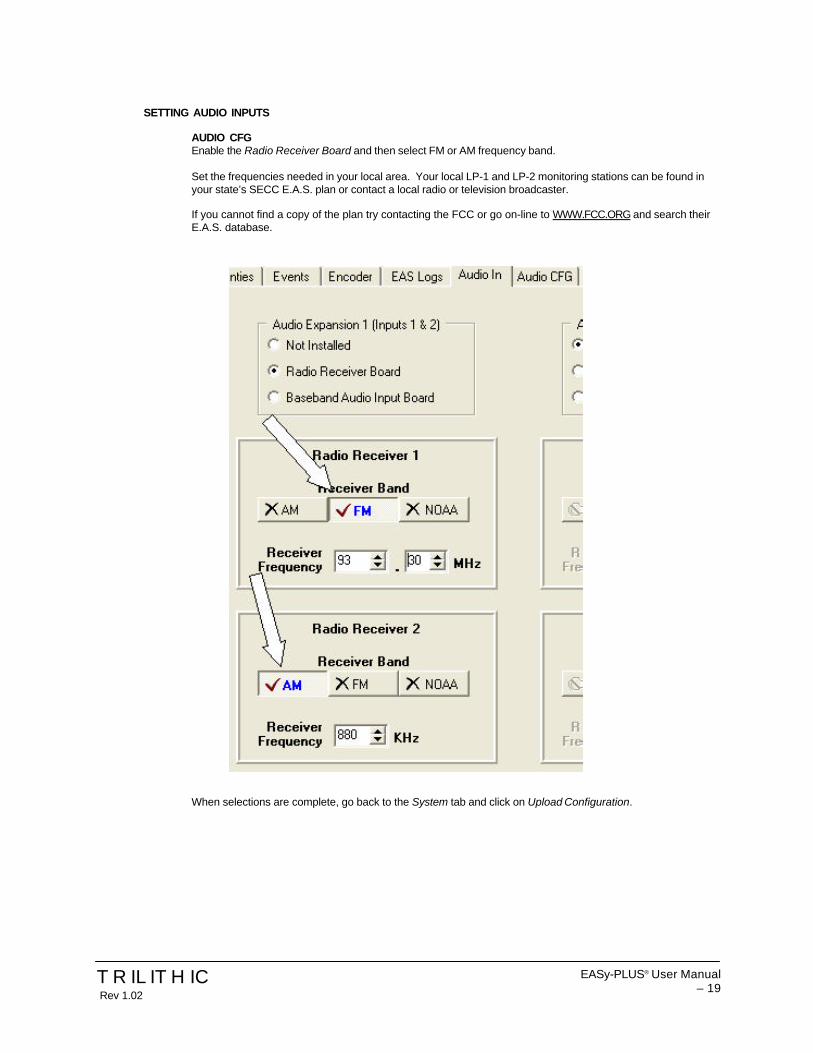
SETTING AUDIO INPUTS
AUDIO CFGEnable the Radio Receiver Board and then select FM or AM frequency band.
Set the frequencies needed in your local area. Your local LP-1 and LP-2 monitoring stations can be found inyour state’s SECC E.A.S. plan or contact a local radio or television broadcaster.
If you cannot find a copy of the plan try contacting the FCC or go on-line to WWW.FCC.ORG and search theirE.A.S. database.
When selections are complete, go back to the System tab and click on Upload Configuration.

EASy-PLUS® User Manual20 –
TRILITHICRev 1.02

EASy-PLUS® User Manual – 21
TRILITHIC Rev 1.02
SECTION 6
EASy-PLUS® Encoder/Decoder Installation and Wiring
6.1 INTRODUCTIONThe EASy-PLUS® receives E.A.S. messages from up to six audio sources (internal or external), decodes the message, andoperates Cable System equipment to replay the message for subscribers. In addition, messages can be originated by theuser via local or remote control of the EASy-PLUS®. The E.A.S. audio sources for the EASy-PLUS® include internal AM/FM/NOAA radios and external audio inputs that can be connected to any known E.A.S. audio source. E.A.S. audio is decodedby the internal AFSK circuitry, sorted, and then interpreted to determine the type of emergency or test. The locations codesfor which the emergency applies, and other information supplied in the E.A.S. header are also decoded. If a voice messageis contained in the E.A.S. message, it is recorded for playback to subscribers. E.A.S. messages then pass through a seriesof tests to determine if the message matches predefined, user configurable filters and parameters for your location. E.A.S.activation of the cable system then automatically occurs. To play an E.A.S. message to your subscribers, the EASy-PLUS®
activates TTL drivers and Contact Closures, as well as sending commands via RS-485 and High Data Rate AFSK. TheEASy-PLUS® also supplies pertinent video and re-encodes and plays the E.A.S. FSK header and recorded audio. The TTLdrivers, Contact Closures, and RS-485 commands activate your interface equipment (i.e. I.F. switching, comb generator,baseband character generators) throughout the headend to provide the emergency audio and video to all channels of thecable system. In addition to the E.A.S. messaging capabilities, the EASy-PLUS® logs all received and transmitted mes-sages to a printer, the LCD display, and it’s internal log storage area.
7.2 INSTALLATION AND WIRING OF THE EASY-PLUS® ENCODER/DECODERTypical installation of the encoder/decoder requires the operator to attach radio antenna inputs at the Audio Expansion 1coaxial input connectors, attach AUDIO and CG VIDEO Outputs to either an I.F. source modulator or audio input to a combgenerator, and attach either TTL control line output to I.F. switching devices or a contact-closure output to the comb genera-tor. Optional control of the Motorola OM-1000 QPSK modulator is accomplished by using a secondary contact-closureattached to the red and black terminals at the rear of the OM-1000.
7.3 PINOUT DESIGNATIONS AT THE REAR PANEL OF THE EAS-yPLUS® ENCODER/DECODER.asf

EASy-PLUS® User Manual22 –
TRILITHICRev 1.02
Par
alle
l Por
t
TRIL
ITH
IC E
AS
y P
LUS
FCC
ID
P4V
-EA
SY
-PLU
S-1
MO
DE
M -
TE
LEP
HO
NE
EX
PA
NS
ION
Aud
io E
xpan
sion
1A
udio
1
A
udio
2A
udio
Exp
ansi
on 2
Aud
io 3
Aud
io 4
CG
VID
EO
IN
O
UT
TTL
EX
PA
NS
ION
Com
1
Com
2
RS
-232
I1+
I1-
I2+
I2-
G 0
1+ 01
- 02+
02-
03+
03-
G
+RI -
RI
+LI -
LI
G +
RO
-RO
+L0 -L0
G 0
4+ 04
-
G 1
2
3
4
5
6
7
8
9
10
G
G C
1 NO
1 NC
1 C2 N
O2 N
C2 C
3 NO
3 C4 N
O4 G
AU
DIO
INP
UTS
TTL
OU
TPU
TS
AFS
K S
WIT
CH
AU
DIO
OU
TP
UT
S CO
NTA
CT
CLO
SU
RE
S
AU
DIO
SW
ITC
HIN
PU
T /
OU
TP
UT
- +
G -
+ -
+ G
- +
RS
-485
DAT
A
AM or FM Antenna Leads
RS-485 Data Cable for MessengerII CG interface (optional)
Balanced Audio Output for CombGenerator or I.F. Source Modulator
Contact-Closure Wires to Connect toComb Generator
Contact-Closure Wires to Connect toRed & Black Terminals of OM-1000
Standard Parallel Printer Cable.
Null-Modem Serial Cable to Connect to PC/Laptop during software setup (supplied)
TRILITHIC EASy-PLUS®
Encoder/Decoder forEmergency Alert Systems
RE
AR
PA
NE
L E
AS
y-P
LUS
®

EASy-PLUS® User Manual – 23
TRILITHIC Rev 1.02
SECTION 7
I.F. (Composite I.F., Aux. I.F., Single I.F.) INTERFACE and INSTALLATION
7.1 INTRODUCTION Single I.F. ReplacementComposite I.F. (both visual and aural intermediate carriers on the same coaxial cable) replacement is a technique whichis used to change the program content on a channel without altering the RF output carrier frequency or amplitude. Withthis technique you will need to install an I.F. switch in the composite I.F. loop-through on the rear of the modulator orprocessor housing (i.e. the channel’s rack mount assembly). Generally, modulators have this I.F. loop on the back of thehousing. In some cases, you may be able to install the loop into the housing to implement this type of switching. For theE.A.S. application, the alternate I.F. signal will be taken from an independent distribution system which will be explainedas you move through this manual.
Single (Composite) I.F. Switch Installation (SW-1)The first step when assembling the E.A.S. system is to install an SW-1 or SW-4 switch on the rear of each modulator orprocessor. The SW-1 is a three terminal device used to substitute the current I.F. source with an alternative I.F. source.The SW-4 switch is a two terminal device with a terminal strip localize as a contact-closure for such chassis as the S-AContinuum modulators and processors.
For each SW-1 installed, you will need two (2) 75 Ohm cables of equal length about three (3) to six (6) inches in length.The next step will cause a brief interruption of the channel involved while the I.F switch is being connected, but the signalwill return once the switch is installed.
Connect the 75 Ohm cable from the I.F. OUT of the modulator or processor to the I.F. IN of the SW-1 switch. Connectthe I.F. OUT of the SW-1 switch to the I.F. IN of the same modulator or processor. See the following diagram. You will
I.F. signal fed from the LS-16PLossless Splitter
Normal I.F. IN fed from the I.F. OUTof the modulator or processor
Normal I.F. OUT fed to the I.F. INof the modulator or processor
EAS IN
SW-1I.F. OUT I.F.
TRILITHIC

EASy-PLUS® User Manual24 –
TRILITHICRev 1.02
connect the EAS IN at the SW-1 switch later in this procedure.
Repeat this procedure on all modulators and processors that have a composite I.F. loop-through on the rear of theirhousing.
7.2 Selecting a “Designated E.A.S. Channel” at I.F.You will assign one channel on the cable system as the “Designated E.A.S. Channel”. This is the channel on which allE.A.S. alerts and messages received via your Local Primary monitoring stations (i.e.: AM, FM, or NOAA) will bedisplayed. Depending on installation techniques used, these messages and alerts will appear in the form of a gen-lockedcrawl message over either the existing video or over a full page blue background. Selecting a low priority channel (onewhich is not trapped or scrambled as it enters every home on the system) as the “Designated E.A.S. Channel” isoptimum. Generally, a community access channel, government channel, or character generator channel in the VHFtelevision band (i.e.: ch. 2-13) is ideal to use for the “Designated E.A.S. Channel”.
NOTE: IN ALMOST ALL INSTANCES A MODULATOR WITH A COMPOSITE I.F. LOOP WILL BE USED FOR THE“DESIGNATED EAS CHANNEL”. THERE ARE EXCEPTIONS, SUCH AS BASEBAND OR CHARACTERGENERATOR EAS SYSTEMS OR COMBINATIONS OF BASEBAND AND I.F. SYSTEMS. THESE EXCEP-TIONS WILL BECOME APPARENT IN EACH INTERFACE SECTION OF THIS MANUAL.
7.3 LS-16P Lossless Splitter Placement and ConnectionThe LS-16P is a precision I.F. distribution amplifier (D/A) which has a 20dB continuously variable precision attenuator forI.F. alignment on each of its 16 output connections. The LS-16P is also used to insert a DC drive voltage on the outputdrop cable’s center conductor for activating each SW-1 or SW-4 switch, as well as other LS-16P input connections whenthe EAS system is activated.
For most applications, multiple LS-16P(s) will be needed. In all installations, the first LS-16P, which receives its input

EASy-PLUS® User Manual – 25
TRILITHIC Rev 1.02
from the I.F. source modulator, should be labeled by the customer as the “Primary LS-16P”.Any other Primary LS-16P output port may be used to drive Secondary LS-16P(s) input ports or SW-1 and SW-4switches.
For example, in a typical headend of 46 channels you will need three (3) LS-16P(s). One LS-16P will serve as thePrimary and the two (2) remaining LS-16P(s) will serve as Secondaries. Total channel capacity will be twelve (14) portsfrom the Primary LS-16P, with the remaining two (2) ports of the Primary feeding two (2) Secondary LS-16P(s). Two (2)times sixteen (16), or thirty (32) ports from the Secondary LS-16P(s) added to the fourteen (14) ports leftover from thePrimary LS-16P totals 46 ports.
As shown in the following diagram, one (1) LS-16P will serve up to sixteen (16) remotely located SW-1 and/or SW-4equipped modulators and processors and/or Secondary LS-16P(s). When installing the LS-16P, place in bays or rackswhere their distribution coverage will be maximized. See the following diagrams.
Typical LS-16P Placement and Connection.
Bundled drop cable feeding I.F. switches
LS -16P

EASy-PLUS® User Manual26 –
TRILITHICRev 1.02
The composite I.F. distribution system is now installed.
7.4 Auxiliary I.F. Switch Installation (SW-4)The SW-4 switch is used to locally activate a contact closure on the rear of a modulator or processor enabling theinternal I.F. switch built into the chassis. The E.A.S. I.F. signal and DC current are fed to the input port of the SW-4switch from the LS-16P. The signal passes through the switch to the Aux. I.F. Input port on the rear of the modulator orprocessor. The DC current is blocked at the input to the SW-4 and converted to a normally open (N/O and N/C) contactclosure. The N/O terminal of the SW-4 should be attached to the rear of the modulator on the appropriate screw terminalto cause the internal I.F. switch to activate when the LS-16P distribution system sends its signal to the SW-4. The groundterminal on the SW-4 should also be attached to an appropriate grounding point on the modulator or processor.
Rear View
Front View
LS-16P
15 13 11 9 7 5 3 1I.F. IN
OFFON
TESTLS-16P??TRILITHIC
16 14 12 10 8 6 4 2Input from I.F.source modulator
I.F. output to any other LS-16P Lossless Splitteror any other Aux. I.F. Input or any other SW-1 orSW-4 switch located at a modulator or processor.
LS-16P
PS
LS-16P LS-16P
Primary LS-16P
E.A.S. MAST IN MAST OUT GND
MAST INGND
TTL Control Line from Encoder/Decoder pins G and 1. Useheadend audio wire.

EASy-PLUS® User Manual – 27
TRILITHIC Rev 1.02
7.5 Single (Composite) I.F. Source Modulator Installation (IFS-3)The I.F. modulator receives its video signal from the CG VIDEO OUT at the rear of the EASy-PLUS® and audio from theterminal strip and modulates these signals onto I.F. subcarriers. Once the IFS-3 source modulator is mounted, connectthe RF OUT port to the I.F. IN port on the Primary LS-16P.
7.6 Precision I.F. Level Alignment of the LS-16P Lossless SplitterThe LS-16P was designed for precision I.F. output level adjustment. In most instances, different modulators or proces-sors require different I.F. input levels to maintain proper RF output levels due to the absence of an AGC at the I.F. stage.It is imperative that the headend maintain the same R.F. output level on each channel during an entire E.A.S. sequenceof events. When alternate I.F. levels match those I.F. levels which are currently present at the rear of the modulator orprocessor, system wide stability of the trunk amps, pilot carriers, slopes, R.F. levels and scrambling systems will bemaintained.
DC power is delivered through the coaxial cable’s center conductor to enable the Secondary LS-16P(s), the SW-1(s),and the SW-4(s) switches.
CAUTION: DO NOT INSTALL FIXED OR VARIABLE ATTENUATOR PADS IN THE INPUT OR OUTPUT CABLES OFANY LS-16P LOSSLESS SPLITTER. ELECTRICAL SHORTING OF THESE DEVICES MAY OCCUR.
The I.F. alignment procedure consists of setting the output level of the I.F. source modulator and then setting the outputlevels on the Primary and Secondary LS-16P(s) for proper I.F. levels at the rear of the modulators and processors. TheMaster Gain on all LS-16P(s) is factory set to unity gain. This adjustment should not need to be reset. Each 20dBpotentiometer on the front panel of the LS-16P is factory set to 0 dB loss (i.e.: 42 dBmV output on each port of the LS-16P if the IFS-3 is set to 42 dBmV output.)
The test point on the front panel of the LS-16P(s) is to check for signal presence ONLY. No test alignment measure-ments should be made at this test point.
7.7 Procedure for precision I.F. Alignment:1. Set the output level of the I.F. source modulator to maximum and then pad its output down to 2 dBmV higher
than the highest I.F. level on your modulators/processors (typically 32-42 dBmV). Set the audio carrier level13-17 dBmV down from the video carrier.
2. Turn all J1 - J16 dip switches on the front panel of the Primary LS-16P to OFF (disabled), except for those dipswitches which control the feeds of the Secondary LS-16P(s) INPUTS. These dip switches will remain ON(enabled) at all times.
3. Enable the I.F. alignment mode in the menu system of the EASy-PLUS® encoder/decoder.4. Using a spectrum analyzer or field strength meter connected to the trunk line test point, identify the channel
under alignment.5. If applicable, be sure to disable any I.F. AGC switches on all modulators in the headend under I.F. alignment.6. Looking at the channel under alignment on the spectrum analyzer or field strength meter, note the output level.7. Turn the dip switch ON (enable) for the channel under setup, ONLY. This will enable the SW-1 or SW-4 switch
at the rear of the modulator or processor under setup. You should now see the “I.F. Alignment Screen” appearon the television on the channel under test channel.
8. Using the respective potentiometer J1 - J16 on the front of the LS-16P for the channel under alignment, turnthe potentiometer counterclockwise until the exact R.F. output level is achieved on the spectrum analyzer orfield strength meter.
9. Turn the appropriate dip switch back OFF (disable) on the LS-16P.10. Proceed to the next channel and repeat steps 4 through 10 until all channels are aligned.11. Turn the I.F. AGC(s) ON for all modulators.12. At the keypad of the EASy-PLUS unit, take the menu system out of I.F. alignment.13. Turn all dip switches ON (enable).
CAUTION: The EAS system will not trigger in the automatic mode for an EAS alert while the system is in the “I.F.Alignment” mode.
You have now completed the composite precision I.F. alignment procedure.

EASy-PLUS® User Manual28 –
TRILITHICRev 1.02
SECTION 8
COMB GENERATOR INTERFACE and INSTALLATION

EASy-PLUS® User Manual – 29
TRILITHIC Rev 1.02
Par
alle
l Por
t
TRIL
ITH
IC E
AS
y P
LUS
FCC
ID
P4V
-EA
SY
PLU
S-1
MO
DE
M -
TE
LEP
HO
NE
EX
PA
NS
ION
Aud
io E
xpan
sion
1A
udio
1
A
udio
2A
udio
Exp
ansi
on 2
Aud
io 3
Aud
io 4
CG
VID
EO
IN
O
UT
TTL
EX
PA
NS
ION
Com
1
Com
2
RS
-232
I1+
I1-
I2+
I2-
G 0
1+ 01
- 02+
02-
03+
03-
G
+RI -
RI
+LI -
LI
G +
RO
-RO
+L0 -L0
G 0
4+ 04
-
G 1
2
3
4
5
6
7
8
9
10
G
G C
1 NO
1 NC
1 C2 N
O2 N
C2 C
3 NO
3 C4 N
O4 G
AU
DIO
INP
UTS
TTL
OU
TPU
TS
AFS
K S
WIT
CH
AU
DIO
OU
TP
UT
S CO
NTA
CT
CLO
SU
RE
S
AU
DIO
SW
ITC
HIN
PU
T /
OU
TP
UT
- +
G -
+ -
+ G
- +
RS
-485
DAT
A
Rea
r P
anel

The Best Thing on Cable
9710 Park Davis DriveIndianapolis, IN 46235
(317) 895-3600
P/N 0010224001 Made in U.S.A.
TRILITHIC?

EASy-PLUS® SYSTEMS
INSTALLATION AND OPERATION MANUAL
Emergency Alert SystemModel: EASy-PLUS® Encoder/Decoder
Revision: 1.02
The Best Thing on Cable?TRILITHIC