model engineers_ workshop - february 2016
TRANSCRIPT

7/24/2019 Model Engineers_ Workshop - February 2016
http://slidepdf.com/reader/full/model-engineers-workshop-february-2016 1/77
FREE BOOK *
£ 4 . 5 0
ENGINEERING GROUP
A SENSITIVEPILLAR TOOLNick Farr Breathes New
Life into an Old Drill
SMARTPHONESin the Workshop
THE GREAT MAGAZINE FOR HOBBY ENGINEERS
CO VER FE A TUR E
3D PRINTINGSimon Davies makessome really useful bits
M E X 2 0 1 6 E N T E R
T H IS Y EA R ’S
CO M P E T I T IO N
E N T R Y FO R M
I N S I D E
Join the conversation about this issue: www.model-engineer.co.uk FEBRUARY 2016
N o . 2 3 8
Miniature InternalCombustion Engines*When you subscribe (New UK Print + Digital and Print Subscribers only)

7/24/2019 Model Engineers_ Workshop - February 2016
http://slidepdf.com/reader/full/model-engineers-workshop-february-2016 2/77 www.emcomachinetools.co.uk
We regularly ship worldwide Please contact us for stock levels and more technical detail
MORE MACHINES AND ACCESSORIES ON LINE
Our machines suit the discerning hobbyist as well as blue chip industry
All of our prices can be found on our web site:
Precision machines made in Italy for the discerning engineer!ineer!
PRO Machine Tools Ltd.
17 Station Road Business Park, Barnack,Stamford, Lincolnshire PE9 3DW
tel: 01780 740956 • fax: 01780 740957
email: [email protected]
ACCESSORIES
Lathe Chucks, Drill Chucks, TippedTools, Boring Bars, QCTP, HSS Tools,
End Mills, Slot Drills, Machine Vices,Clamping Sets, Slitting Saws, Arbors,
Boring Heads, Radius Mills, DROs,Rotary Table, CNC fits, Collet Chucks,
Collet Sets, Flanges, Face Mills,
Shell Mills and Much More...
All lathes and mills are backed by anextensive range of tools and accessories
d
Ceriani 400Series Mill
Ceriani 203 Lathe •Centre height - 100mm •Centre distance - 500mm •Swing over gap - 260mm •Spindle bore - 20 or 30mm •Motor - 1 HP •Weight - 80 Kgs
•Optional splash-back andsafetyguard
•Semi Norton gearbox •Four selectable feed rates plus screw cutting • Vari-speed option
•ISO30 Spindle• Table size - 580 x 150mm• Travel - 420 x 160 x 300mm
(XYZ)•1.5 KW Motor •100-3000 rpm vari-speed•Weight - 150 Kgs

7/24/2019 Model Engineers_ Workshop - February 2016
http://slidepdf.com/reader/full/model-engineers-workshop-february-2016 3/77
3February 2016
On the Editor's Bench
Published by MyTimeMedia Ltd.Enterprise House, Enterprise Way,
Edenbridge, Kent TN8 6HF+44 (0)1689 869840
www.model-engineer.co.uk
SUBSCRIPTIONSUK - New, Renewals & Enquiries
Tel: 0844 243 9023Email: [email protected]
USA & CANADA - New, Renewals & EnquiriesTel: (001)-866-647-9191
REST OF WORLD - New, Renewals & EnquiriesTel: +44 1604 828 748
Email: [email protected]
BACK ISSUES & BINDERSContact: www.myhobbystore.co.uk/contact
Website: www.myhobbystore.co.uk/magazines
MODEL ENGINEERING PLANSContact: www.myhobbystore.co.uk/contact
Website: www.myhobbystore.co.uk/me-plans
EDITORIAL Editor: Neil Wyatt
Tel: +44 (0)1689 869 912Email: [email protected]
PRODUCTIONDesigner: Yvette Green
Illustrator: Grahame ChambersRetouching: Brian Vickers
Ad Production: Robin Gray
ADVERTISING Senior Account Manager: Duncan ArmstrongEmail: [email protected]
Tel: 01634 238893
MARKETING & SUBSCRIPTIONSSubscription Manager:
Kate Hall
MANAGEMENTPublisher: Julie Miller
Group Advertising Manager: Rhona BolgerEmail: [email protected]
Chief Executive: Owen DaviesChairman: Peter Harkness
© MyTimeMedia Ltd. 2016 All rights reserved ISSN 0959-6909
The Publisher’s written consent must be obtained before any part of thispublication may be reproduced in any form whatsoever, including photocopiers,
and information retrieval systems. All reasonable care is taken in the preparationof the magazine contents, but the publishers cannot be held legally responsiblefor errors in the contents of this magazine or for any loss however arising from
such errors, including loss resulting from negligence of our staff. Reliance placedupon the contents of this magazine is at reader’s own risk.
Model Engineers’ Workshop, ISSN 0959-6909, is published monthly withan additional issue in August by MYTIMEMEDIA Ltd, Enterprise House,
Enterprise Way, Edenbridge, Kent TN8 6HF, UK. The US annual subscriptionprice is 52.95GBP (equivalent to approximately 88USD). Airfreight and mailing inthe USA by agent named Air Business Ltd, c/o Worldnet Shipping Inc., 156-15,146th Avenue, 2nd Floor, Jamaica, NY 11434, USA. Periodicals postage paid atJamaica NY 11431. US Postmaster: Send address changes to Model Engineers’
Workshop, Worldnet Shipping Inc., 156-15, 146th Avenue, 2nd Floor,Jamaica, NY 11434, USA. Subscription records are maintained at
dsb.net 3 Queensbridge, The Lakes, Northampton, NN4 7BF. Air Business Ltd is acting as our mailing agent.
Bob Smith got in touch after reading my warnings about zinc fumes. He pointedout that the condition is cumulative and can be fatal, and supplied a link to anAmerican website that reported the untimely death of a metalworking blogger whohad died following an attempt to ‘burn off’ zinc from a batch of metal. Ironically hehad made sure that colleagues were all kept away from the fumes. It is importantto remember that any zinc containing metal, such as brass or galavanized steel,as well as materials with cadmium plating or containing lead etc. can all releasepotentially harmful levels of metals on heating whether by smelting, brazing,forging or welding. Please take car to reduce the risks by working in a wellventilated environment and using proper protective gear as appropriate whenheating such materials.
FUME FEVER
On The Editor’s ChairToday, the Editor has a new chair!
Over Christmas, an occasionallyniggling bad back decided to turn into areal problem. Sorting out the fit of myMother-in-Law’s back door finally finishedme off. With more than thirty minutes in achair locking me into an L-shape andrequiring a longer period of rest, I had todo two things – first book a doctor ’sappointment, and second, order a proper8-hour typing chair with lumbar support,
instead of the rather droopy one I havebeen using. So I got one on next daydelivery… it has just arrived! It’s givenme plenty of time to overcome the badback and then lose a molar. I will sparethe details, but back painkillers maskedthe toothache really well, so I only foundout when my face ballooned...
So after wallowing in bathos, back tothe chair. Like all the best flat pack things,it totally justifies the male imperative tothrow away the instructions. I omittedthis step and spent more time trying tofigure out what the Coupling CPT wasthan actually building up the chair.Coupling CPT is easily identified as theonly un-named object in the assemblydiagram, being the bit that holdseverything else together.
Perhaps the worst instruction was to‘take off the plastic sleeve from side
screw of the coupling CPT and thenscrew the adjustment screw A. This keptme going for several minutes, for afterremoving ‘Adjustment Screw A’ Icouldn’t see what the point was, so I putit back together. I was nervous on thispoint as failure of Adjustment Screw A isone reason why the old chair was so badfor my back.
Well, it’s all together now, I just have tobear in mind the remarks. Fortunately,‘don’t heat or take apart the gas lift’ issimple enough to understand. I will tryto avoid the places of high humiditylevel – usually only a problem when Ispill my tea. I am concerned thoughabout how to ‘avoid the contact with thewarmth spring’. Does this mean the chaircan only be used in the chill of winter?
After 30 days of exploitation, I will notforget to strengthen the screws of themechanism under seat.Adjustment Screw A.

7/24/2019 Model Engineers_ Workshop - February 2016
http://slidepdf.com/reader/full/model-engineers-workshop-february-2016 4/77
E N G I N E E R I N G S U P P L I E SG N E GE N E NN G E EN G I N E R I N GN E GN G I N EN G N E E I N GE N N E NE N G E GN E EN G E IE N G N EG I N E N GG EG N E NEE N G I N E E I N GE G E E NEE NEE N G I N E E R I N G S U P P L I E SE N G I N E E R I N G S U P P L I E SS P PUS PS U PS U P PUUSS U PS US UUS L I E SL EL I EL EI SSE SIS U P P I E SS U P PPP P LLL I E SS U P PPP P I E S
®
Visit us online: www.avontapdie.co.uk It’s what we do. It’s all we do. Isn’t it time you chose a specialist? Any tap, tapset, tapping drill, die, die nut -any where -and when you need it. We’ve been doingthis for more than 25 years, supplying the world with vital taps, dies and cutting &threading tools of the highest quality. No job is ever too big nor too small, everyorder for us is just as important -it’s our reputation at stake as well as your deadline.
Any tap, any die
Any whereNo jack of all trades, not uss not us
F R E E
S h i p p i n g 25 y r s
Ex p e r i e n c e
On l i n e
Di s c o u n t s
Ma s s i v e
Se l e c t i o n
C a l l 0 1 4 5 4
3 2 4 5 4 6

7/24/2019 Model Engineers_ Workshop - February 2016
http://slidepdf.com/reader/full/model-engineers-workshop-february-2016 5/77
NEW ADDITION TO THE WARCOWELL ESTABLISHED RANGEOF VARIABLE SPEED MILLS
WM12 COMPACT MILL• Supplied with 10mm and 3/8” Whit. drawbars• Captive drawbar to eject tooling• Available with metric or imperial leadscrews
£650
ITEM Nos. 3201/3202 SPECIFICATION
Drill chuck capacity 13mm
Maximum end milling capacity 12mm
Table size 400 x 120mm
No. of tee slots 3
Cross traverse 150mm
Longitudinal traverse 350mm
Vertical traverse 210mm
Spindle taper 2MT
Spindle stroke 42mm
Number of speeds Variable
Speed range 100 – 2,000rpm
Head tilt left and right 90° – 0 – 90°
Motor 600w
Dimensions L x W x H 510 x 470 x 800mmto end of handle grips
Weight 54kg
Prices include VAT and UK mainland delivery excluding Highlands and Islands.
Features for the
above milling machines include:• Digital depth gauge• Rev. counter• Captive drawbar to eject tooling• Back gear for maximum torque in lower speeds• Sensitive fine feed to spindle• Adjustable gibs to all axes
WM14 VARIABLESPEED MILLINGMACHINE• Now with larger table 500 x 140mm• 2MT spindle• Motor 500w
£755
WM16 VARIABLESPEED MILLING
MACHINE• Table size 700 x 180mm• 2MT• Motor 600w
£998.00 Available in Metric andImperial versions
WM18 VARIABLE
SPEED MILLINGMACHINE• Table size 840 x 210mm• 3MT spindle• Motor 1100w
£1,365.00
WarcoSpring Open Day12th March 2016 • 9:00am - 1:00pmWarco House, Fisher Lane, Chiddingfold, Surrey GU8 4TD

7/24/2019 Model Engineers_ Workshop - February 2016
http://slidepdf.com/reader/full/model-engineers-workshop-february-2016 6/77
www.model-engineer.co.uk Model Engineers’ Workshop
Contents9 IMPROVEMENTS
TO A MYFORDSUPER 7 LATHE
Like all lathe owners,
David Salter couldn’t
resist a few modifications.
14 DIGITAL SCALESFOR A SOUTHBEND 9A LATHE
Fitting low cost scales and
readouts to Tony Hills’
American machine.
20 IMPROVEMENTSTO A BANDSAW
Making a budget saw a bit
easier to use, with Stub
Mandrel.
25 3D PRINTING FORMODEL ENGINEERS
Yes, they really can do useful
things – Simon Davies give
some worked examples!
33 CNC IN THE(MODEL ENGINEERS’)WORKSHOP
Marcus Bowman gives advice
on work holding that will
benefit manual mill users too.
37 INDEX FOR ISSUES225 TO 236
Another twelve issues
carefully cross referenced by
Barry Chamberlain..
44 FLAT BELTFRANKENSTEIN
Gary Ayres creates a
strange hybrid betweena mill and a dril.
46 THE MOBILE‘SMART’ PHONEIN THE WORKSHOP
Want to make your tech earn
its keep? Howard Jenning
shows you how.
50 MYFORD ML7RPOWER CROSS SLIDE
Fitting and using Keith
Wraight’s well executedaddition.
57 AN OLD BENCH DRILLADAPTED TO MILLING
Old pillar drill? – Alan Wain
turns a hefty drill into a mill!
64 CAROLS,CAPPUCCINOS ANDLOFTED SOLIDS
Bob Reeve adds a final
postscript to his Kei Car
Challenge.
68 A BENCH DRILLINGAND TAPPINGMACHINE
Old pillar drill? – Nick Farr
goes the other way,and produces a sensitive
pillar tool.
20
25
6
SUBSCRIBE TODAY! AND MAKE GREAT SAVINGS
PLUS RECEIVE A FREE
MINIATURE INTERNAL
COMBUSTION ENGINES BOOK
See page 23 for details.

7/24/2019 Model Engineers_ Workshop - February 2016
http://slidepdf.com/reader/full/model-engineers-workshop-february-2016 7/77
FREE BOOK *
£ 4 . 5 0
ENGINEERINGGROUP
A SENSITIVEPILLAR TOOLNick Farr Breathes New
Life into an Old Drill
SMARTPHONESin the Workshop
THE GREAT MAGAZINE FOR HOBBY ENGINEERS
CO VER FE A TUR E
3D PRINTINGSimonDaviesmakessomereallyusefulbits
M E X 2 0 1 6 E N T E R
T H IS Y EA R ’S
CO M P E T I T IO N
E N T R Y FO R M
IN S I D E
Jointheconversationaboutthis issue:www.model-engineer.co.uk FEBRUARY2016
N o . 2 3 8
Miniature InternalCombustion Engines*Whenyousubscribe(NewUKPrint+DigitalandPrintSubscribersonly)
M C o e r. i nd d 5 / 0 / 0 6 0 :
February 2016
Visit ourWebsite
for extra content andour online forum
RBelt Drive for an X3 Mill
In response to requests from forum members, a
further updated 3D model has been added. It isworth taking a look just to see the incredible range
of viewing options and features available within
Adobe Acrobat viewer.
http://www.model-engineer.co.uk/sites/7/
documents/X3D3.pdf
Other hot topics on the forum include:
› Hot Air and Stirling Engines
›Understanding the Square/Cube Law
› Workshop Radio – To DAB or Not To DAB?
›Recommendations for Neat Cutting Oil
AND:
› Do YOU finish every project before
moving on?
Nick Farr made this sensitive pillar
tool from an old drilling machine, see
page 68 for the full story.
ON THE COVER ›››
Coming up...in the March issue
3 ON THE EDITOR’S BENCH Tall tales from the Editor’s Workshop
31 READERS’ TIPS This month - handling humidity.
42 SCRIBE A LINE Feedback on recent articles in MEW.
71 ON THE WIRE Time to go hunting wolves!
63 MEX 2016 ENTRY FORM Enter your workshop tooling in this year’s
Model Engineer Exhibition!
Regulars
www.model-engineer.co.uk
CLASSIFIEDS EXTRA SUBSCRIBE ARCHIVE SUPPLIERS
HOME FEATURES WORKSHOP EVENTS FORUMS ALBUMS
7
SMALL TOOLS, GADGETSAND TIPS SPECIAL!Our Next Issue will be packed to the gunnels with a
range of short projects, tips and gadgets, each one
a complete idea you can try in your workshop.
INCLUDING:
• Making HSS Tool Holders
• Coming out of the Kitchen - with CarverSaw!
• Electric Power Drawbar
PLUS:
Full plans to build a full size precision boring head

7/24/2019 Model Engineers_ Workshop - February 2016
http://slidepdf.com/reader/full/model-engineers-workshop-february-2016 8/77
Just a small selection from our current stock
• Telephone enquiries welcome on any item of stock. • We hold thousands of items not listed above.• All items are subject to availability. • All prices are subject to carriage and VAT @ 20%. • We can deliver to all parts of
the UK and deliver worldwide. • Over 7,000 square feet of tools, machines and workshop equipment.
tel: 01903 892510 • www.gandmtools.co.uk • e-mail: [email protected]
Opening times: 9am -1pm & 2pm – 5pm Monday to Friday. Closed Saturdays, except by appointment.
G and M Tools, The Mill, Mill Lane Ashington, West Sussex RH20 3BX
Buy online now at: www.gandmtools.co.uk
Amolco1/2” Cap.Bench
Drill. 1ph, VGC,£350.00plus vat.
Myford ML7R Lathe,Stand, Tooled,1ph, VGC,
£975.00 plus vat.
Clarkson Tool& CutterGrinder,
Well Tooled,3ph,
£625.00plus vat.

7/24/2019 Model Engineers_ Workshop - February 2016
http://slidepdf.com/reader/full/model-engineers-workshop-february-2016 9/77
›
9February 2016
doesn't work at 200 rpm – the quality ofconstruction and, yes, the old fashionedlook of a real centre lathe. I finished upbuying a good secondhand machine of1991 vintage with a star/delta dual voltage3 phase motor as I had the intention ofpowering from a 220 V single phase input
3 phase output inverter to give variableoutput speed. I managed to install thelathe safely in our 42nd floor 900 sq ftflat overlooking the airport in Hong Kongalthough sadly in a small spare roomwith no window rather than take over thesitting room and view from the balcony(see photos 1 and 2). Pity, I know, itwould have been good to have a lathewith a view.
ElectricalThe motor is rated at 2.3 A at 220 V 3phase AC, giving just over 700 W power. Ichose a TECO 7300 CV 1 hp inverter witha remote control pod. This offers goodturn down to as low as 5 Hz without lossof torque. I mounted the inverter on apurpose made bracket on the left handend of the stand (mine is the Myfordindustrial stand), photo 3. It is under the
I decided on the Myford for severalreasons, despite the much higher pricetag. Simplicity of layout, availability
of real low speeds - I always lovedscrewcutting and my sort of screwcutting
Improvements to a
Myford Super 7 LatheDavid Salter, a retired RN marine engineer officer and engineer/yachtsurveyor describes some modifications to his machine.
1
2
Myford Super 7 in micro-workshop.
The view over HK Airport that the Myford will never have.
I bought my Myford when I was
approaching retirement and
when I found some usable cashlying around not being used
properly, such that I could start
using my time properly building
steam engines. For a couple of
years before, I had been steadily
studying available machines,
comparing their capabilities
and deciding what I wanted for
myself. I realised that when I
finally got the lathe, it was going
to be almost 25 years since I was
last at sea and so 25 years since
I had done any turning at all.
Worse, it was over 43 years since
I finished my apprenticeship –
time to be cautious.

7/24/2019 Model Engineers_ Workshop - February 2016
http://slidepdf.com/reader/full/model-engineers-workshop-february-2016 10/77
10 www.model-engineer.co.uk Model Engineers’ Workshop
overhang of the bench which protectsagainst damage and I only need to accessthe display during setup. I installed theremote control pod for On/Off/Reverseand speed control on the front of the stand
just under the lip with an emergency stop/ double pole no-voltage-release switchimmediately next to it for best access.Using the NVR switch enables me toisolate the lathe and inverter fully whennot in use, rather than just the lathe withthe inverter left live.
The lathe came with a 12V DC halogenwork light. Rather than wiring thisseparately, I took AC power from theinverter input busbar and reused aredundant 12V printer PSU strapped to theback of the inverter to supply the light.This way it is also isolated when the NVRswitch is put to off. Since installation, theinverter and motor have performedfaultlessly. I set max frequency to 50 Hz asI have no need for step up speeds. I alsodid not wish to risk overstressing themotor by exceeding the rated outputspeed. Being able to turn down the speed
is what is important. The standard rangeof belt combinations remain unchanged ofcourse, giving 8 speeds from 210 to 2105rpm ungeared and 27 to 270 rpm gearedand I do use these as the baseline for any
job because I want to keep the inverterand motor operating at as near to normaldesign conditions as possible for most ofthe time. However, having the ability to
has established a very good reputationin the engineering industry. Fenner'sspecification indicates that the linkbelting at least equals the performanceof conventional rubber V-belts and inadverse oil and dirt conditions usuallyoutperforms it. Since I installed the newbelt, it has proved to be totally successful,quick to install, with ample friction toavoid any overtensioning and almostsilent in operation. Okay, it was moreexpensive than the standard belts at£36 but this was for a 2 m length whichprovides enough for 2 complete changesand spares besides. I fitted it while I wasstill working when my consultancy ratewas enough that I can persuade myselfthat I probably saved myself around£400 by taking 5 minutes to fit the Fennerinstead of 4 or 5 hours for the fixed lengthspare. For anyone else interested in thisbelting, I am confident that it shouldbe readily available in UK from a widenumber of sources.
Lathe toolingAround the same time as I bought thelathe, I was given a box of assortedsmallish lathe tools courtesy of a friendclearing an elderly relative's house.Included in this box were a number ofbrand new 10mm shank indexable toolswith lots of spare CCMT 06 inserts; mostof the remainder comprised HSS tools
reduce speed for short periods isabsolutely invaluable, while facing a largecross feed surface for instance, checking aset up before starting a cut or eliminatinga surface chatter on a cut. I have notbothered with fitting a frequency meter asI find I can gauge the speed turn down Ineed very satisfactorily by ear.
Headstock drive beltWhen my lathe was delivered, the driveV-belts were aging and oil softened,particularly of course the headstock belt.Changing the primary drive belt was easybut I hesitated before starting dismantlingthe headstock to install a new one-piecedrive belt. I tried a cheap set of link beltingfrom an online supplier but found itunsatisfactory. It stretched once installedand became more of the consistency ofa large elastic band. To achieve enoughtension to eliminate slippage from thesmooth plastic V-surface, the side loadingon the countershaft bearings was sohigh that they complained, plus the links
stretched further as they warmed upcausing yet more slippage. Completelyunacceptable ... and of course I hadalready cut off the old oily original belt.I was about to face the inevitable andstart stripping the headstock when Ifound that RS Components in HK stockreal Fenner PowerTwist Plus A/13/4Llink belting (photo 4). This link belting
3
5
4
6
Electrical installation on Myford stand – emergency stop/NVR,inverter and remote control pod.
3 ⁄ 8 " and 10mm tooling.
Fenner PowerTwist Plus A/13/4L link belting for headstock drive.
Quick change toolholders.

7/24/2019 Model Engineers_ Workshop - February 2016
http://slidepdf.com/reader/full/model-engineers-workshop-february-2016 11/77
›
11
Improving a Myford
February 2016
measured from the cutting tip down to thebase of the shank is:
(Height of headstock spindle above topslide) minus (toolholder bottom flangethickness)
For 0.24" flange, max tool height= 0.625 – 0.240 = 0.385" (9.78mm),ie will accept 5 ⁄ 16 ", 8mm and 3 ⁄ 8 "tools but not 10mm
For 0.30" flange, max tool height= 0.625 – 0.300 = 0.325",ie will accept 5 ⁄ 16 " or 8mm toolbut not 3 ⁄ 8 " or 10mm
There are a number of solutions:
a. Use smaller tools. Sure, you can restrictyour tooling to 8mm or less. This isthe size that mini and micro lathes use.Using them on a Super 7 significantlyreduces the cutting capability of theMyford. Tool overhang from thetoolholder cannot be much over 0.5inch for even quite moderate cuts andfor any interrupted cut simply doesn'twork as the tool bends. By comparison,I routinely use up to an inch overhang
and sometimes more on 10mm tools,especially turning with tailstock orbetween centres as it keeps the top slideaway from the tailstock. The Myfordlathe with the correct size tooling is abig strong and stiff machine, capable ofquite large cuts when required. Anyway,since I already had the 10mm tooling,restocking with smaller tooling wasn'tan option for me.
b. Selective installation. Obviouslysome tools like small boring bars andthreading tools present no problem.Any tool where the cutting tip has beenreduced in height above the shank baseto 8mm or less can be installed andadjusted to centre height, even if theshank is 3 ⁄ 8 inch, 10mm or even 12mm.Such tools include older many timesreground HSS tooling and most boringtools where the cutting tip is mountedat around ½ shank height. However,
a. Except for the Myford toolholders, theheight adjusting studs were all too shortby some .250 inch. To allow adjustmentfull down, the studs need to be longenough to permit the adjusting screwbottom flange to extend to 0.700 inchabove the toolholder top face. I renewedthem with longer studs, after which theyworked as designed.
b. The bottom flanges of most of thetoolholders were far too thick to permitthe tool cutting tip to be adjusted downto centre height for 10mm and 3 ⁄ 8 inchtooling unless the cutting tip has beendropped by grinding the top surface ofthe tool. Thicknesses varied from 0.24inch for the original standard Myfordholders up to 0.30 inch.
Any solution to the dilemma requiredquantitative knowledge. Accuratemeasurement on my lathe gave:
similarly of 10mm or 3 ⁄ 8 inch (9.5mm)shank. Also in this treasure trove boxwere a rear parting toolpost with partingtoolholder and several individual quickchange toolholders which matched theMyford toolpost although they appearedto be from different manufacturers. Theset of Myford's own HSS tools I hadbought with the lathe were all 3 ⁄ 8 inchshank with grooving for use with thescalloped adjustable base. A selection ofthese is shown in photos 5 and 6.
I wanted to use the 3 ⁄ 8 inch and 10mmtools and in particular the 10mm righthand knife indexable tool:
• Because I had them. • Because the extra tool stiffness
compared to 8 and 6mm tools enablesbetter finishes and also use of larger tooloverhangs, important when workingclose to the tailstock to avoid contactbetween the top slide and the tailstock.
• Because I want the best tool stiffnesswhen doing interrupted cuts suchas facing castings and machining
crankshafts. • Because I have a bad habit of using the
RH knife tool for universal turning andwould spend an inordinate amount oftime resharpening a HSS tool, whereaschanging an indexable insert takes a fewmoments and I can reuse the worn insertin the roughing tool when I do rememberto change tools
I also wanted to use the quick changetoolholders on front and rear toolposts asmy standard so as to avoid the endlessroutine of resetting height with shim packsat every tool change. The quick changetoolholders all had space for tools withshanks of at least 12mm and some aslarge as 14mm, giving the impression thatsuch tools may work. So I happily startedinstalling the beautiful indexable tools inthe toolholders, only to be totally set backin my tracks to discover that I could notget the tool cutting tips down to anywherenear centre height. Okay, time to put thesteam engine plans aside and go back tosome engineering.
Inspection and measurement of all thetoolholders revealed quite largevariations. It turned out I had a real mixedbag. There was the original equipmentthat came with my lathe, a Dicksontoolpost with the Myford label on it and 3Myford toolholders, 2 standard and 1
boring with the groove in the base forround tools. The rear parting toolpost andtoolholder work really well and are easy tokeep sharp and adjusted to centre height.The front parting toolholder was clearly ofdifferent manufacture but fitted well andcould easily be adjusted to correct centreheight (although more on that later). TheDickson-copy rear toolpost presented noproblem and toolholders wereinterchangeable; however, it wasn't quiteso easy with the remaining 7 toolholders.Most had sharp corners which madeengagement with the toolpost camsdifficult; okay, easily fixed with a lap and abit of care. Much, much moreproblematical were the dimensions of thefront toolpost toolholders. Full downheight adjustment should give lowest tooltip position, with the base of thetoolholder bottom flange touching the topslide top face, BUT:
Inches mm
Height of cross slide tableabove lathe bed
1.432 36.37
Height of top slide top
surface above cross slidetable
1.443 36.65
Height of headstockspindle centreline abovetop slide surface
0.625 15.87
7
Standard toolholder set full down on top slide.
It was interesting to note that the centreheight above the lathe bed = 3.500 inchesexactly although I understand that onsome lathes there is frequently slightvariation in this centre height.
The last of these dimensions, the heightof the headstock spindle centreline abovethe top slide top surface, is the crucialdimension for tool height setting since thelowest the tool tip can be adjusted to iswhen the toolholder is full down flush tothe top surface of the top slide (see photo7). Therefore, using standard or boringtoolholders, limiting maximum tool height

7/24/2019 Model Engineers_ Workshop - February 2016
http://slidepdf.com/reader/full/model-engineers-workshop-february-2016 12/77
12 www.model-engineer.co.uk Model Engineers’ Workshop
all the full height tools including allindexable knife, rough cut and profilingtooling still cannot be used.
c. Modify the underside of the toolholderby grinding a step such that it canoverhang the edge of the top slidetop surface (note that this feature isused on the standard front toolpostparting toolholder to enable useof a 0.5 inch depth parting blade),photo 8. This step gives much morefreedom for tool height and indeedcan allow use of larger tooling up to12mm tool height with 12mm shank.However, such a stepped toolholderhas the major disadvantage thatthe overhang prevents the toolpostfrom being rotated relative to thetopslide and hence restricts use ofthe toolholder only at 90° or 180° tothe top slide (photo 9). This createsa major restriction to accurate turningwhen using the tailstock centre as thetopslide cannot be oriented parallelto the lathebed and hence cannot beused to set offsets. With the parting
toolholder, the step is far enough awayfrom the toolpost pivot to allow around20° of adjustment (photo 10). Anotherfactor against stepping the toolholdersis that it is not easy to get the grindingof the step done on an existingstandard toolholder because any self-respecting owner of a good qualitysurface grinder wheel would not permitit to be used for edge grinding into acorner. So these stepped toolholderswill probably only work if one buysa new set already stepped (presentlyavailable from RDG Tools).
d. I believe that the best final anddefinitive fix is to reduce the thicknessof all the toolholder bottom flangesby surface grinding since it restoresthe ability to use any tooling up to10mm shank thickness without anyrestriction. Even the 'copy-Dickson'holders are made of good quality steeland hardened; so there is still amplestrength in the toolholder bottomflange to prevent any distortion asthe tool setscrews are tightened. Isimply stripped all the holders of studsand setscrews and found a friendlyengineering works who surface groundthe bottom faces of all the holders(including the original Myford standardones and the 2 boring bar holders) to
Myford own spares on www.myford.co.uk Flange 0.245 inch (6.22mm)
RDG Tools on www.rdgtools.co.uk Flange 0.264 inch (6.71mm)
Chronos on www.chronos.ltd.ukFlange 0.283 inch (7.19mm)
My calculation as above gives maximumtool tip heights for these as follows:
For 0.245" flange, max tool tip height= 0.625 – 0.240 = 0.385" = 9.78mm,i.e. will accept 5 ⁄ 16 ", 8mm and 3 ⁄ 8 " toolsbut not 10mm
For 0.264" flange, max tool tip height= 0.625 – 0.264 = 0.361" = 9.17mm,For 0.283" flange, max tool tip height= 0.625 – 0.283 = 0.342" = 8.67mm,i.e. these last two will accept 5 ⁄ 16 " or8mm tools but not 3/8" or 10mm
By comparison, my modified toolholdersall have bottom flange thickness of 0.228"(5.79mm). Maximum tool tip height =0.625 – 0.228 = 0.397" = 10.08mm and willaccept all 3 ⁄ 8" and 10mm tools. ■
reduce the flanges to 0.228 inch (0.003inch of flexibility included in this). £5per holder that I hadn't planned for butwell worth it. The result is that I nowhave 10 interchangeable toolholderswhich I can use for any size tooling upto 10mm. Even the 2 boring tool holdersaccept 10mm square shank toolscompletely satisfactorily as the toolspans the V-groove whereas smallershank tools partially tip into the groovewhen secured losing the tool geometry.
New ToolholdersI have found new standard toolholdersavailable online from 3 suppliers; theremay be others I have not found or used.Some make claim to be usable with10mm tooling. This is only half the truth.All the standard toolholders will accept10mm shank tools, true, and 12mmalso, but the cutting tip will be too highon all toolholders to be set correctly toheadstock centre height.
I have checked the bottom flangethicknesses with the suppliers fortoolholders being marketed at present,which are:
9 10
Modified toolholder on top slide showingrestriction of positioning.
Standard parting toolholder on top slide showing steppedbottom face and limitation of positioning.
8
Modified toolholder showing stepped bottom face and standard parting toolholder.

7/24/2019 Model Engineers_ Workshop - February 2016
http://slidepdf.com/reader/full/model-engineers-workshop-february-2016 13/77

7/24/2019 Model Engineers_ Workshop - February 2016
http://slidepdf.com/reader/full/model-engineers-workshop-february-2016 14/77
14 www.model-engineer.co.uk Model Engineers’ Workshop
Two particular aspects concerned me.I did not wish to keep switching onand off each scale every time they
were used or keep peering closely at eachscale while operating the handles. I liketo watch what is going on rather than bedistracted by bending over the machineto try and see the tiny readouts in thereading head of each scale.
So I decided to build a single unit readoutusing commercially available remotereadouts which you can now purchase foraround £30 each (the three axis readoutwas not available at the time). I took the
electronics out of each remote unit andcombined them into a large case, completewith its own mains driven 3v power supply.The controls were combined in a singlekeyboard and a further internal mainspower supply of 1.5v was provided for thescales themselves. Photograph 1 showsthe result, which has worked satisfactorilyfor several years.
A DRO for the latheMore recently I acquired a South Bend 9Alathe of wartime vintage which replaceda very old but faithful 5 inchg IXL lathe.Being a 9A it has a gearbox for the leadscrew and power cross feed which the IXLdidn't. Unfortunately, it too was in needrenovating and after a complete overhaulthat included a lot of scraping, a repaint,new motor, stand, and a second handbed that was in better condition than the
under the length of the bed to allow forthe movement of the saddle as it traversedthe bed and in the end I abandoned this astoo complicated.
As I had seen other scales attachedalongside the cross slide, I decided tofollow this practice. An excellent article inMEW 87 and 88 adopts this configurationfor a Myford. I also decided that, as thetailstock side of the saddle has two holesin the centre tapped 3 ⁄ 8 BSW (photo 2), Iwould use these. They are for thetravelling steady and other fitments.
The next consideration was the length of
travel. With the cross slide fully extendedoutwards, I measured the travel to a pointwhere the tool tip under normal conditionswould be beyond the centre and this wasapproximately 4.5 inches. Knowing that ascale actually travels a little further than thestated length, I decided to use a 4.0 inchscale and purchased one at a show from anexcellent retailer of these devices (ref.1).
As in all the other scales on the mill, Ithought of using the bracket which comeswith the scale and dreamed up difficultways of connecting the reading head tothe cross slide, with equally complicatedways of fixing the bar to the saddle. Aftermany trials, it suddenly dawned on methat it would be much simpler to fix thehead and move the bar! It makes nodifference to the reading as this comesfrom the relationship of the two parts - notwhich bit is moving. This allowed the headto sink into the web space of the bed and
original, I am now pleased with the resultsI get. I have yet to replace the cross slidescrew, which has excessive backlash but,learning from my mill experience, I decidedto fit the machine with digital scales for thecross slide and saddle traverse.
Intrigued by how others have fittedscales to their machines I researched themany forums on the web and, cameacross Compucutters of Coventry whomarket an interface between scales and acomputer. The interface is calledCompUguide and this article was toinclude the building of this but, for
reasons explained later, this was not to beand I reverted to using two independentreadouts built into one unit with mainspower supplied in a similar fashion to mymill. Building the readout is the subject ofthe second part of this article. The firstpart that follows is attaching the scales tothe lathe.
The cross slide scaleI toyed with many ideas of how to fit thecross slide scale. An early idea was tosling the scale under the bed and providea link from the rear end of the cross slidesuch that when the cross slide moved,the scale underneath moved as well.The attraction was that it would leavethe saddle uncluttered by the scale foroperations involving close use of thetailstock. It would require some form ofguidance and support at right angles
Digital Scales for a
South Bend 9A LatheTony Hills fitted a low cost DRO to his lathe using Chinese scales and individual readouts.
1
First attempt at a DRO using individual read outs combined into one case.
I have owned a George Taylor
vertical mill of considerable
vintage for some time and after
restoring it, I was never happy
about the backlash in the X axisof the table. I was persuaded by
the arguments of using digital
readouts to overcome this (often
referred to as 'Chinese scales')
and I set about providing one
for each axis. This taught me
valuable lessons in designing
their fixings to the machine.

7/24/2019 Model Engineers_ Workshop - February 2016
http://slidepdf.com/reader/full/model-engineers-workshop-february-2016 15/77
›
15
South Bend goes Digital
February 2016
with only one end of the bar attached tothe cross slide, lining up the scale wasalmost automatic. This meant that thehead was lower than the top surface of thecross slide even when a guard was fitted.Also, by not using the end fixing bracketswhich come with the scale, a further 3 ⁄ 4 inch was gained on travel. Severalproblems solved in one!
Fitting a scale using the existing holeswould render them unusable unless thescale is temporarily removed - which thenmakes the scale unusable. So I decided toprovide support pillars for the scale, butinstead of using bolts to secure the scale,additional pillars would extend beyond thescale and provide new 3 ⁄ 8 tapped holes.
Although this allows the fixed steady to beused, it would be a further two inchestowards the tailstock, but I was preparedto live with this. The tailstock would alsonot be able to come as close to the chuckunless the saddle is moved furthertowards the headstock but to date I havenot found this a problem.
The parts which make up the fixing areshown in photo 3 and assembled inphoto 4 with the front splash guardremoved to show the reading head. I havenot attempted to provide drawings ordimensions as these will vary according toyour own lathe and the parts are verystraightforward. Note that the forwardextension pillar has been turned down formost of its length to accommodate thebattery compartment in the reading head,thereby allowing the head to sit as low aspossible. Also note the extension pillarseach have an additional part that uses the
cross slide, being careful to limit the depthof the holes to avoid breaking through to
the slide way (photo 5). Pillars thenprovide support for both ends of the guardbut only one end of the bar.
The Saddle scaleI decided to mount the scale along the rearof the bed, tucked well under the slide wayoverhang which, when combined witha guard, should provide protection fromswarf and fluid.
The general arrangement is very simple,this time fixing the bar and moving thereading head by direct attachment to thesaddle. With the saddle at the headstockend, the scale was positioned beneathsuch that the reading head was directlyunder the connection box at the rear ofthe saddle and to the extreme right of thebar. The fixing holes were then marked.Unfortunately, I cannot get access easilyto the rear of the lathe, so this meant
replacement hole with a rubber stopscrewed to these. This is to prevent the
tailstock from colliding with the scale, butthe stops can quickly be removed if theholes are required.
A guard has been provided whichprevents swarf and cutting fluid fromgetting on the scale. It has a separate frontsplash guard which can be removedquickly if access to the reading head isrequired.
There is also a steel tube which carriesthe cable from the head to the rear of thesaddle. This is to protect the cable fromdamage and the tube was simply a pieceof rusty brake pipe, de-rusted and buffed!It terminates in a right angle gas pipefitting which I found in the scrap box asthe tube was not long enough to bend at aright angle. A copper tube would alsosuffice and if long enough, could becarried directly into the connection box.To attach the bar and the guard a 5 ⁄ 16 BSFwas drilled and tapped at each end of the
3
5
2
4
Parts for attaching scale to cross slide.
Drilling pillar holes in cross slide.
Existing tapped holes in saddle for travelling steady.
Cross slide scale assembly.
I thought of using the bracket which comes with the
scale and dreamed up difficult ways of connecting the
reading head to the cross slide, with equally complicated
ways of fixing the bar to the saddle. After many trials,
it suddenly dawned on me that it would be much
simpler to fix the head and move the bar!

7/24/2019 Model Engineers_ Workshop - February 2016
http://slidepdf.com/reader/full/model-engineers-workshop-february-2016 16/77
16 www.model-engineer.co.uk Model Engineers’ Workshop
completely dismantling it and turning thebed around. I drilled and tapped two 5 ⁄ 16thBSF holes through the bed (one of whichis shown in photo 6) and then remountedthe saddle to complete the installation ofthe transfer plate.
A new U shaped bracket was created tolink the reading head with the transferplate. I did not use the bracket suppliedwith the scale even though this wouldconveniently have been closer to the topof the transfer plate, as I wanted to havethe bracket underneath the head and notabove it. This way a continuous guard cancover the scale without the need for a slotto accommodate the bracket.
A further steel pipe carries the cable fromthe reading head to the connection box inmuch the same way as the cross slide. Thishas a small bracket with grommet to givesupport from the transfer plate. All theparts can be seen separately in photo 7 and assembled in photo 8 with the frontsplash guard omitted for clarity.
The rear mountand connection boxThe rear mount is simply a solid bar (9x 1.25 x 0.25 inch BMS) that is fixed tothe saddle by two ¼ BSF cap screws,utilising an existing tapped hole in thetailstock rear wing and one which I drilledand tapped in a matching position in theheadstock rear wing. The bar providessupport for the connection box andtransfer plate and requires a radius filedout of it along the top edge for cross slidelead screw clearance.
I could repeat the concept of providingfurther pillars with matching tapped holesto the original but as at present I have noattachments that will use these holes Ihave not done so. I can always make theselater if, for example, I was lucky enough toacquire a taper turning attachment thatuses these holes. Finding such luxuries fora South Bend is nigh impossible in the UKand although they do occasionally appearfor sale in the US, the cost of shippingusually rules them out. I have downloadedan article for making one, so this may wellgo on my 'to do' list if I have a project thatrequires one! If so, it would be necessaryto relocate the connection box furtherdown, with the cross slide steel tubeextended to avoid the attachment.
The connection box is die-castaluminium and serves simply to provide a
break in the cables between the readingheads and interface for easy maintenance
it was in essence a flexible steel conduit!Cut the ends off, pull out the inner plastictube and it is ready. It is perhaps not as oilproof as purpose made conduit, but if thatwill be a problem then the inner plastictube can be left in and used.
A connection was required and Imachined this out of hexagon steel,providing a 5 ⁄ 8 BSF on one end and asmooth extension on the other thatallowed the conduit to slide over and besecured with a jubilee clip.
Photograph 9 shows the overallarrangement, with the lid removed toshow the connection panel in place.
Although the scales have perfectly goodLCD read outs, in their positions and
and dismantling. It is dealt with in moredetail in the second part of this article. Thebox uses one of the rear bolts and anextended transfer plate bolt for securingto the rear mount.
Finally, the cables between theconnection box and readout needprotection and I looked to flexible conduitas the answer. Investigation of this provedthat it was very expensive as it wasusually sold only in long lengths.However, by chance my wife asked me toreplace the shower hose as it was gettinggrubby and she was fed up trying to keepit clean. A replacement was purchased
from B&Q at around £5.50 and as I wasabout to throw the old one away I realised
7
9
8
10
Parts for attaching saddlescale to rear of bed.
Hardware connections to connection box.
Saddle scale assembly.
The completed readout.
6
Hole drilled in rear of bed forsaddle scale support.

7/24/2019 Model Engineers_ Workshop - February 2016
http://slidepdf.com/reader/full/model-engineers-workshop-february-2016 17/77
›
17
South Bend goes Digital
February 2016
crucial moment and I find the block mostuseful for steadying.
Which way up the wires lead out doesnot really matter. What does is that the
correct colours are noted for each track onthe board. Photograph 12 shows thetracks and, reading from left to right, theirpurpose is: 1.5v Neg; Data; Clock; 1.5v Pos.I do not know if there is a convention but Iconnect black to -ve, red to Data, blue toClock and white to +ve. Clearly, colourshave no meaning other than to ensure thatthe correct connections are made at theother end in the connection box.
Check that the tracks are isolated fromeach other and no solder has 'crossedover'. A gentle scrape with the point of ascalpel may clean the board between thetracks that have been soldered and anyflux should be cleaned off withmentholated spirit or a proprietary pcb
cleaner. Then feed the cable through thecover hole and reassemble the board inthe front casing.
If you have left the back and bar completewith shims in place, reassembling thecomplete reading head is a reverse of theabove. The reading scale on the bar mustbe facing up and vertically the right way aswell. After wasting a lot of time I learnt thatyou could not put it facing the right waybut upside down as it simply will not read!Lower on the front assembly and turn thewhole unit over pressed against a board orcard. It is only then a matter of tighteningthe screws.
Make sure that the other end of the wiresto those soldered to the board areseparated and not in contact with eachother. Then temporarily place the button
delicate but relatively easy process.However, if the scales are new, you shouldbe aware that such action will invalidatethe warranty, so you may care to stick with
the plugs however unsatisfactory theymay be.
Before starting, remove the battery if thisis still in place. Lay the scale face down onsome cloth and, with a watchmaker'sscrewdriver, remove the four screwssecuring the back. One screw next to thebattery compartment is a machine screwwhilst the others are self tappers. Itsposition should be noted. Place a smallpiece of plastic over the back to hold thescrews in position and then turn the wholescale over. Hold the bar in position andgently remove the front. Note that there isa very thin gib strip and top and bottomshims and try to keep these in position.Set the back and bar to one side.
Turn the front unit over and remove thescrews securing the printed circuit board.Lift out the board but note that it has to goback the same way, otherwise the LCDconnections will not match those on asmall bar embedded in the rubber pushbutton moulding. Set the front casing, LCDdisplay and rubber moulding aside.
Soldering the wires to the tracks is trickybut not difficult. I use a 15 watt solderingiron and grind the tip to a very fine point. Itin the wires and tracks separately beforefinally soldering them together whichgives a much faster solder and thereforeless heat transfer on the board.Photograph 11 shows the set up. Notethe wooden block which I use to givesupport to my hand. The slightest tremblecan move the fine wires too much at a
covered as they are by guards, they aretotally impractical to read whilemachining. A remote read out was mysolution, shown in photo 10.
I intended to use a CompuGuideinterface between the scales and acomputer but despite two attempts at this(one built by myself and one suppliedready built) I could not get it to work withlinear scales. The interface would workcorrectly with vertical scales, but these arebigger and would not fit the X axis in theway I wanted. Consequently, I abandonedthe CompuGuide and reverted to usingindependent readouts. I would cautionanyone contemplating using theCompuGuide to avoid linear scales andonly use vertical scales.
The attraction of the CompuGuide wasthat it provided many additional facilities,including compensating for diametriccutting (i.e. twice that of the scale output)which is not available directly from thelinear scale. So that I could quicklycalculate any diameter reduction Idecided to add a calculator forconvenience and purchased one for £5.50in the high street. Adding this saveshaving to find a calculator, often buriedunder a pile of clutter!
Connecting the reading headsto the connection boxThe cable used to make the connection isfour core shielded and sufficient lengthfor two reading heads can be obtained
when cropping the attached cables to theindependent readouts (see later), includingthe special plugs.
Each reading head is provided with aremoval cover to expose access for afour-way plug. The plug matchescorresponding tracks on the printedcircuit. Personally I do not like these plugs.They do not mate properly and all seem tobe different sizes to the guides in the head,some being tight and others being loose.The last thing that is wanted is for one tocome loose and lose connection. It willmean removing the guard and refixing,probably only to come off again at somestage. This is no mean feat if it is the Zaxis reading head and will require leaningover the lathe to do so.
The solution is to solder the leadsdirectly to the printed circuit. This willrequire dismantling the reading head togive access to the board which is a
11 12
Soldering leads toreading head pcb.
Components of areading head showing
the four pcb tracks.
Each reading head is provided with a removal cover to
expose access for a four-way plug. The plug matches
corresponding tracks on the printed circuit. Personally I
do not like these plugs. They do not mate properly and all
seem to be different sizes to the guides in the head, some
being tight and others being loose. The last thing that is
wanted is for one to come loose and lose connection.

7/24/2019 Model Engineers_ Workshop - February 2016
http://slidepdf.com/reader/full/model-engineers-workshop-february-2016 18/77
18 www.model-engineer.co.uk Model Engineers’ Workshop
battery in the holder and check thateverything is working correctly. I thenused a small amount of Araldite to keepthe wires in place on the head.
The connection panelA small piece of strip board was cut tofit inside the box and secured by means
of the extended screw from the transferplate that comes through the back of theconnection box. Two 2BA nuts are used toset the correct height of this strip board.
The board has four two-pole connectionblocks together with a futher singletwo-pole block that is slightly larger, allpurchased from Maplin (ref. 2). Thesmaller four blocks allow connection forthe Data and Clock lines of each readinghead (only two of these are connected atthe moment but there is provision for moreconnections if required in the future). Thelarger block is for connection of +ve and-ve lines to all reading heads as it does notmatter that they are connected together.
As the wire from the reading heads isvery thin, I solder a pcb pin to each beforeit is inserted into the connection block.This gives a more secure fitting and lesslikely for the wire to be severed whilstscrewing down. Photograph 13 shows
damaging the card cover I machined apiece of Perspex which when placed infront of the plate allowed the bolt heads tobe below the Perspex surface.
I experimented with various fixings forthis readout and initially tried a 13 inchgooseneck for microphones from Maplin.This was anchored to a plate on the wallusing an old speaker wall mounting that Ino longer required.. However, the weightof the readout proved too much for thisand it sank slowly into an unreadableposition. In the end, I had one six inchgooseneck which was too stiff on its own,so I bought a second one and put the twotogether. This was perfect, giving the rightflexibility but also being stiff enough tosupport the readout in any chosenposition. Finally, I added a fuse holder to
the case and the completed case is shown(photo 14).
Power suppliesPlease note that AC mains is involved andall safety precautions should be observed.Never take mains for granted - it reallycan be lethal!
The mains input is reduced to 12v by aminiature transformer I purchased fromMaplin. In fact, this has two 12v outputs,so only one lead and the central tap areused, the other simply being terminated ina insulated terminal. Two voltages arerequired - one at 3v DC for the readoutsand one at 1.5v DC for the scales. I usedtwo Velleman kits from Maplin because Ihad them, but the power supplies arefairly simple affairs, using a standardcircuit for the LM317 voltage controller.The small number of components is
the arrangement, but one wire has notbeen connected to show the pin solderedto the wire. A good length of cable (up to75mm) is left within the box to allow theboard to be removed and worked uponwith relative ease.
Connection between
connection box and readoutSix cores will be required for cablingbetween the connection box and thereadout, only two of which carry thereading head power. The power is thendistributed to the both heads within theconnection box.
Any configuration of cable can be used.Termination at the readout end willdepend on how it is connected to theboard. I prefer four or two-way headerconnections obtained from Maplin.
Building the ReadoutThe readout is built in a plastic instrumentcase purchased from RS Components(ref. 3) which has an aluminium frontplate. The plate is machined on the millto provide all the necessary holes and cutouts but is fairly thin and therefore wasnot good for countersunk screws. To avoid
15 16
The power supply sub panel and connections. The individual readouts mounted and connected to the power supply.
13 14
The rear connection panel. The readout case with incoming cables.
Please note that 230v AC mains is involvedand all safety precautions should be observed.
Never take mains for granted - it really can be lethal!

7/24/2019 Model Engineers_ Workshop - February 2016
http://slidepdf.com/reader/full/model-engineers-workshop-february-2016 19/77
19
South Bend goes Digital
February 2016
size without the need to constantly checkthe diameter with a micrometer. Whilst I
accept to some degree David Clark'sassertion that a readout for the Z axis isnot necessary (MEW 152), I have foundthe ability to return to a particular placewithout the need to set or reset thecarriage stop a boon. The batteries inboth the reading heads and readouts areno longer required and therefore neverneed replacing.
Was it worth the effort? Well, the wholeproject cost about £130 - including thescales and calculator. Each Warco readoutcomes in a magnetic case and can simplybe placed on a metal plate fixing in muchthe same position as my readout.However, I enjoyed the challenges thisproject threw up and improved some ofmy skills along the way, whilst now beingmore confident in my turning - and I don'thave to worry about batteries! ■
Power panel
A separate panel with an on/off switchwas constructed (photo 18) for thefront of the lathe stand. I chose a doublepole double throw rocker switch toIP65 standard as this will switch 230vmains and with the possibility of sudsflying around at some time, I preferredthis additional protection. The power isconnected through the contactor above,effectively using the no volt drop outshould power fail for any reason. Allinternal wiring in the stand is contained in20mm plastic conduit and, of course, earthconnections abound.
The smaller rocker switch to the right isfor a low cost suds system I have in mind,but this will use 12v for switching and doesnot, therefore, need the added protection.
Final assembly and useIt only remained to test the completedreadout. This is always nerve rackingwhere mains is concerned, but the onlyfault was that, despite careful checkingalong the way, one readout had itsdata and clock lines reversed, so itgave gibberish displays. After a while Idiscovered the error and it then workedperfectly.
The complete assembly can be seen inphoto 19. In use it is excellent, allowingme to turn diameters down with
confidence until very near the required
inexpensive and further savings can bemade by using the rectifier diodes andsmoothing capacitors only once, feedingtwo LM317s with their associated resistorsand capacitors. A circuit diagram can besourced by looking for an LM317 datasheet on the internet.
The kits as supplied have a claimedrange of 1.5v to 35v, this being set by a4.5k ohm trimmer. This value does notgive good results at the 1.5v or even 3vlevel, so it is better to use a 220 ohmtrimmer for the 3v and a 100 ohm for the1.5v. With these, the voltages can be setvery accurately, usually in the centre of thetrimmer rotation.
The completed supplies and connectionboard on their sub panel can be seen inphoto 15.
The readoutsI have used two single readouts whichI purchased from Warco (ref. 4). Theseare very good quality and I removed theboards from the cases. The only alteration
was to remove the battery container leadsand solder longer ones in their place,with headers at the other end. It was alsonecessary to crop the output leads to abouteight inches and solder header plugs tothese. Again - be aware that doing so willinvalidate any warranty, so it may be betterto check that they work before doing this.The leads with their plugs can be used atthe reading head end (see earlier).
The readouts were then mounted on themain panel, but with only three pushbuttons instead of the usual four. I omittedthe on/off button and left thesepermanently on as the power would beswitched elsewhere.
I connected the readouts (alwayschecking that the wires were correctlyoriented) and the incoming leads from thereading heads to the connection board. Thecomplete set up can be seen in photo 16.
The front panelI created a front cover on my computerusing a desk top publishing programme,but it could be created using the drawingfacility in Microsoft Word or similar. Thiswas then printed on thin card and cutout using a craft knife. A final Perspexcover was milled to allow the buttons tocome through and an area to operate thecalculator. All the milled parts making up
the front panel can be seen in photo 17.
17
1918
Front cover and other machined layersforming the front panel.
The completed readout.Switch assembly on lathe stand.
I enjoyed the
challenges this
project threw up
and improved some
of my skills alongthe way, whilst now
being more confident
in my turning - and I
don't have to worry
about batteries!
1. Allendale Electronics Ltd 01992450780 www.machine-dro.co.uk
2. Maplin Electronics 0844 557 6000 www.maplin.co.uk
3. RS Components www.uk.rs-online.com4. Warren Machine Tools (Guildford) Ltd.
01428 682929 www.warco.co.uk
REFERENCES

7/24/2019 Model Engineers_ Workshop - February 2016
http://slidepdf.com/reader/full/model-engineers-workshop-february-2016 20/77
20 www.model-engineer.co.uk Model Engineers’ Workshop
The first, and simplest modificationhas been done by others – butperhaps that’s because it works
and surely as good a reason as any torepeat it? The moving jaw pivots, and thismeans you can’t hold short work withoutsomething to balance the force on the
jaw. Tap an M10 or M12 hole towards thefar side of the moving jaw, but clear ofthe reinforcing web. Pop in a lengthy bolt(photo 2). No more hunting for an exact
Well, it cuts itself a groove in the angle, sonext time it has somewhere to go. Iadjusted the depth stop so the first cutwas a bit deep, making a 1mm deepgroove in the support. I then raised thedepth stop so now the saw blade doesn’tbottom out. The best bit of this is theunexpected side-effect that the sawgroove now provides an excellent way to‘eyeball’ where the cut will fall, rather thanbouncing the blade on top of the work.
Third – widen the moving jaw byscrewing a long, thick plate in front; 3 ⁄ 16
inch or 5mm will do it, ¼ inch would bebetter. Rather than waiting for a suitable
offcut to appear, what on earth is that thickchunk of metal doing screwed to the fixed
jaw? A big chunk of cast iron jaw liner witha crude diamond pattern on it. All it doesis make the fixed jaw thicker than it needsto be. Off it comes and – look it’s just whatwe need to fix to the moving jaw (photo5) to make it wide enough to match thefixed jaw and support work really close tothe saw blade! Perhaps the factory fit theplates to the wrong jaw by mistake?
Fourth, look at the wasted space underthe frame! I popped a rectangle of MDFunderneath (photo 6). For some reasonthis has turned into a sort of elephant’sgraveyard for all my large imperialspanners. I have no idea why.
Fifth, check the gearbox (photo 7). Thisis a ‘just in case’ task, when I looked inmine it was full of a strange fluid likeliquid gold. The worm and wheel weren’tproperly engaged and a lot of bronze had
sized spacer when you want to hold ashort end to one side of the jaw.
Second, get an offcut of hefty 2 inchangle iron and use it to make a properwork support (photo 3). Cut one side ofthe ‘L’ down to about 1¼ inches. Using aplate on top of the vice to align the angle,spot a 5mm through the short leg to set ahole just up and to the left of the hole inthe vice for the length stop that you neveruse. Thread the hole M6 and open the holein the angle enough so you can fix itaccurately (photo 4). Perhaps it sounds abit hit and miss? Maybe, but its better thana pile of packing to support that offcut that
just keeps slipping half way through a cut.But, you may ask, what happens when theblade finishes cutting through the work?
Stub Mandrel adds a few creature comforts to a workshop companion.
Ask which piece of shop
equipment saves the most
effort, and many will reply ‘my
bandsaw’. In a survey of MEW
readers over 50% had bandsaws
and 29% had power hacksaws.
Does this mean the rest have
over-developed biceps? The
best thing about a bandsaw, is
it stops you putting off bigger
jobs, just because you can’t face
sawing through a big chunk of
bar by hand.
With so many bandsaws out
there, and the cheaper ones
having the sort of limitations that come from being built to a
price, several people have found
ways to modify them for better
performance.
Although every owner has their
own favourite ‘tweaks’, here are
a few of my own ideas, most
aimed at increasing usability.
As supplied my bandsaw made
a pretty accurate cut out of the
box; keeping a chunk of metal in
the right place to cut it was the
biggest problem!
Stub Mandrel’s Short End Improvements to a Bandsaw
1
2
The modified bandsaw.
A large bolt used to help balance jaw forces on short workpieces.

7/24/2019 Model Engineers_ Workshop - February 2016
http://slidepdf.com/reader/full/model-engineers-workshop-february-2016 21/77
21
Bandsaw Tweaking
February 2016
been worn off the wheel. It’s possible toremove the driving pulley and realign it.Doing this helped reduce blade throw-offsas well as, hopefully, extending the life ofmy pulley.
Sixth, the biggest problem with mybandsaw is where to put it. It demands acertain amount of space around it, is anawkward shape but is too heavy to lugaround easily. I found some decentcastors, two of them braked, from a bigold computer desk – from the days when acomputer, printer and CRT monitor
hefty reinforcement across each corner(photo 8) and provided useful practice insticking metal back on to thin air, where Iblew holes in the thinner metal!
I was so impressed with the result I hadto treat the finished stand to a coat of sagegreen Hammerite. Well, it had beenlooking a bit shabby since I spilt ferricchloride over it…
Final task – was to buy a really decentbi-metal blade, I get mine from tuff-saws,they hugely outlast plain carbon steelones. ■
weighed about as much as a washingmachine. One thought, most people fitboth locking castors at one end – I fittedthem at diagonal corners, so there’salways one easily accessible.
These were rubber tyred ones, not cheapall-plastic ones, with hefty M8 mountingbolts. After opening the holes for thestand’s feet to 8mm they fitted straight on,but as the frame is only 18-gauge steel thefixing points rapidly collapsed under theweight. Half an hour with the stick welderand a flat bar of black mild steel put a
5
7
43
6
8
Now why don’t the fit the jaws together like this as standard?
If you are brave, remove this cover, but be prepared for oil spill!
Held in place by a single M6 bolt.The simple work supporting extension.
The 7/8 Whitworth Spanner Graveyard.
Reinforced wheel mount.

7/24/2019 Model Engineers_ Workshop - February 2016
http://slidepdf.com/reader/full/model-engineers-workshop-february-2016 22/77
SUBSCRIBE TODAY
CARD PAYMENTS & OVERSEAS
Mr/Mrs/Miss/Ms ....................Initial ...........................Surname ..................................
Address ......................................................................................................................
.....................................................................................................................................
Postcode ................................................... Country .................................................
Tel ............................................................................. Mobile ......................................
Email .......................................................... D.O.B ....................................................
Mr/Mrs/Miss/Ms ....................Initial ...........................Surname ..................................
Address ......................................................................................................................
.....................................................................................................................................
Postcode ................................................... Country .................................................
Postal Order/Cheque Visa/MasterCard MaestroPlease make cheques payable to MyTimeMedia Ltd and write code V847 on the back
Cardholder’s name........................................................................................................
Card no: (Maestro)
Valid from............................... Expiry date.................... Maestro issue no....................
Signature.................................................................................. Date............................
Originator’s reference 422562
Name of bank ...............................................................................................................
Address of bank ..........................................................................................................
.....................................................................................................................................
..................................................................................Postcode ..................................
Account holder ............................................................................................................
Signature ....................................................................................... Date ....................
Sort code Account number
Instructions to your bank or building society: Please pay MyTimeMedia Ltd. Direct Debits fromthe account detailed in this instruction subject to the safeguards assured by the Direct Debit Guarantee.I understand that this instruction may remain with MyTimeMedia Ltd and if so, details will be passedelectronically to my bank/building society.
Reference Number (official use only)
Please note that banks and building societies may not accept Direct Debit instructions fromsome types of account.
SUBSCRIPTION ORDER FORM
POST THIS FORM TO: MODEL ENGINEERS’ WORKSHOPSUBSCRIPTIONS, MYTIMEMEDIA LTD,
3 QUEENSBRIDGE, THE LAKES, NORTHAMPTON NN4 7BF
DIRECT DEBIT SUBSCRIPTIONS (UK ONLY)
Yes, I would like to subscribe to Model Engineers’ Workshop
Print + Digital: £54.00 every 12 months
Print Subscription: £45.00 every 12 months
YOUR DETAILS MUST BE COMPLETED
PAYMENT DETAILS
I WOULD LIKE TO SEND A GIFT TO:
INSTRUCTIONS TO YOUR BANK/BUILDING SOCIETY
Yes, I would like to subscribe to Model Engineers’ Workshop,for 1 year (13 issues) with a one-off payment
TERMS & CONDITIONS: Offer ends 26th February 2016. MyTimeMedia Ltd & Model Engineers’ Workshopmay contact you with information about our other products and services. If you DO NOT wish to becontacted by MyTimeMedia Ltd & Model Engineers’ Workshop please tick here: ❏ Email ❏ Post ❏ Phone.If you DO NOT wish to be contacted by carefully chosen 3rd parties, please tick here: ❏ Post ❏ Phone. Ifyou wish to be contacted by email by carefully chosen 3rd parties, please tick here: ❏ Email
PRINT + DIGITAL SUBSCRIPTION
PRINT SUBSCRIPTION
• Free Miniature Internal Combustion
Engines Book*• 13 Issues delivered to your door
• Great Savings on the shop price
• Download each new issue to your device
• A 75% discount on your Digital Subscription
• Access your subscription on multiple devices
• Access to the Online Archive dating
back to Summer 1990
• Free Miniature Internal Combustion
Engines Book*
• 13 Issues delivered to your door
• Great Savings on the shop price
UK ONLY:
Print + Digital: £56.99
Print: £47.99
EUROPE & ROW:
EU Print + Digital: £64.95EU Print: £55.95
ROW Print + Digital: £64.95 ROW Print: £55.95
HURRY
OFFERCLOSES26th FEBRUARY
2016
Please visit www.mytimemedia.co.uk/terms for full terms & conditions CODE V847

7/24/2019 Model Engineers_ Workshop - February 2016
http://slidepdf.com/reader/full/model-engineers-workshop-february-2016 23/77
SUBSCRIBE SECURELY ONLINE CALL OUR ORDER LINE
http://me.secureorder.co.uk/MEW/V847 0844 243 9023Lines open Mon - Fri - 8.00am - 8.00pm GMT & Sat - 9.30am - 3.30pm GMT.
UK Calls costs 7p per minute plus your phone company’s access charge. Overseas calls will cost more.
Quote ref: V847
TERMS & CONDITIONS: Offer ends 26th February 2016. *Gift for UK ‘Print’ and ‘Print + Digital’ subscribers only, while stocks last.**This digital discount is only available when you subscribe to the ‘Print + Digital’ package. You can still get a great discount on the digital package, please visit the URL stated below for more information.
D I G I T A L
S U B S C R I P T I O N S
A V A I L A B L E O N L I N E !
A great read for allModel Engineering
enthusiasts!
A must read for everyModel Engineering
enthusiast!
Miniature Internal Combustion
Engines by Malcolm Stride
Model engineers have been making
models of internal combustion
engines since the invention of the
real thing, but it has always been
surrounded by a mystique and a
perceived difficulty that has put
many people off.This book by Malcolm Stride is
a great guide to the techniques
involved in producing all the
components required
to build a model
internal combustion
engine. Collected
together is sufficient
information about avariety of engines and
the relevant design
and construction
techniques to assist
prospective builders
to produce a working
model I/C engine.
Miniature Internal
Combustion Engines*
when you subscribe today
Receive a FREE BOOK:W O R T H £ 19 .9 5
SAVE 75%ON DIGITALPRICES**

7/24/2019 Model Engineers_ Workshop - February 2016
http://slidepdf.com/reader/full/model-engineers-workshop-february-2016 24/77
SUBSCRIBE SECURELY ONLINE CALL OUR ORDER LINE
http://me.secureorder.co.uk/MEW/V847 0844 243 9023Lines open Mon - Fri - 8.00am - 8.00pm GMT & Sat - 9.30am - 3.30pm GMT.
UK Calls costs 7p per minute plus your phone company’s access charge. Overseas calls will cost more.
Quote ref: V847
TERMS & CONDITIONS:
Offer ends 26th February 2016. *Gift for UK ‘Print’ and ‘Print + Digital’ subscribers only, while stocks last.**This digital discount is only available when you subscribe to the ‘Print + Digital’ package. You can still get a great discount on the digital package, please visit the URL stated below for more information.
D I G I T A L
S U B S C R I P T I O N S
A V A I L A B L E O N L I N E !
A great read for allModel Engineering
enthusiasts!
A must read for everyModel Engineering
enthusiast!
Miniature Internal Combustion
Engines by Malcolm Stride
Model engineers have been making
models of internal combustion
engines since the invention of the
real thing, but it has always been
surrounded by a mystique and a
perceived difficulty that has put
many people off.This book by Malcolm Stride is
a great guide to the techniques
involved in producing all the
components required
to build a model
internal combustion
engine. Collected
together is sufficient
information about avariety of engines and
the relevant design
and construction
techniques to assist
prospective builders
to produce a working
model I/C engine.
Miniature Internal
Combustion Engines*
when you subscribe today
Receive a FREE BOOK:W O R T H £ 19 .9 5
SAVE 75%ON DIGITALPRICES**

7/24/2019 Model Engineers_ Workshop - February 2016
http://slidepdf.com/reader/full/model-engineers-workshop-february-2016 25/77
SUPPLYING
THE WOODWORKER
& MODEL ENGINEER
SINCE 1984
POWER CAPACITORS LTD
30 Redfern Road,Birmingham
B11 2BH
NO SURCHARGE FOR DEBIT & CREDIT CARD PAYMENTS
BRITAIN’S FAVOURITE PHASE CONVERTERS... CE marked and EMC compliant
FREEPHONE 0800 035 2027 or 0121 708 4522
[email protected] • www.transwaveconverters.co.uk
REMOTE CONTROL STATION £67 inc VAT
2-YEAR WARRANTY/MONEY-BACK GUARANTEE
Suitable for all IMO inverters, this remote pendant allows you to
access the software of the inverter remotely, bypassing the
buttons on the inverter itself. START, STOP, FORWARD, REVERSE,
RUN, JOG, SPEED POTENTIOMETER. NO-VOLT RELEASE
safety feature and two metre
length of 7-core flex as standard.
2-YEAR WARRANTY/MONEY-BACK GUARANTEE
240-volt 1-phase input, 240-volt 3-phase output (i.e. dual
voltage motor required). SOFT START-STOP, SPEED CONTROL,
BRAKING, MOTOR PROTECTION and JOG FUNCTIONS.
Low-Cost, general purpose simplified torque vector control.
Entry level performance suitable for the
majority of applications. Four sizes available
from 0.4kW/0.5hp to 2.2kW/3hp.
5-YEAR WARRANTY/MONEY-BACK GUARANTEE
240-volt 1-phase input, 240-volt 3-phase output (i.e. dual
voltage motor required). SOFT START-STOP, SPEED CONTROL,
BRAKING, MOTOR PROTECTION and JOG FUNCTIONS. Advanced vector control giving optimum
performance at low RPM. Four sizes from
0.4kW/0.5hp to 2.2kW/3hp.
JAGUAR VXR INVERTERS from £264 inc VAT
STATIC CONVERTERS from £264 inc VAT
240-volt 1-phase input, 415-volt 3-phase output.
Single or multi-motor operation via socket/plug or
distribution board. Eight sizes from 1.1kW/1.5hp
to 11kW/15hp.
Ideal solution for
“one machine at
a time” environments. Output retrofits directly to
existing machine wiring loom so no modification
to machine necessary. Manual power adjustment via switch using voltmeter as guide.
3-YEAR WARRANTY/MONEY-BACK GUARANTEE
JAGUAR CUB INVERTERS from £174 inc VAT
5-YEAR WARRANTY/MONEY-BACK GUARANTEE
240-volt 1-phase input, 240-volt 3-phase output
(i.e. dual voltage motor required). SOFT START-STOP, SPEED
CONTROL, BRAKING, MOTOR PROTECTION and JOG
FUNCTIONS. Simplified torque vector control
giving enhanced performance at low RPM.
Four sizes from 0.4kW/0.5hp to 2.2kW/3hp.
3-YEAR WARRANTY/MONEY-BACK GUARANTEE
240-volt 1-phase input, 415-volt 3-phase output. Single or
multi-motor operation via socket/plug or distribution board.
Eleven sizes from 1.1kW/1.5hp to 22kW/30hp. Ideal
solution for multi-operator environments or where
fully automated “hands-free” operation is required
irrespective of demand. Output retrofits directly to existing machine wiring loom
so no modification to machine necessary. Some sizes suitable for welding applications.
ROTARY CONVERTERS from £504 inc VATR
CONVERTERS MADE IN BRITAIN SINCE 1984; 3-YEAR WARRANTY ON ALL
CONVERTER PRODUCTS; BS EN 9001:2008 QUALITY ASSURED MANUFACTURING
ENVIRONMENT; CE MARKED PRODUCTS COMPLIANT WITH EMC REGULATIONS,
THE LOW VOLTAGE DIRECTIVE and BS EN ISO 61000-3-2:2006.
.
NEW iDrive2 INVERTERS from £127 inc VAT
THE
ONLY PHASE
CONVERTER MANUFACTURED IN
BRITAIN TO ISO9001:2008
by POWER CAPACITORS LTD
30 Redfern Road,Birmingham
B11 2BH
Inverter-Metric Motor-RCS packages from £228 inc VAT • Imperial Packages from £298 inc VAT
Ideal for
Myford & Boxford
lathes
Metric Motors from £60 including VAT Imperial Motors from £154 including VAT
SUP P ORT
BRIT ISH
MANUF ACT URI
NG
.
T

7/24/2019 Model Engineers_ Workshop - February 2016
http://slidepdf.com/reader/full/model-engineers-workshop-february-2016 26/77
›
25February 2016
Mindful of a number of commentson the forum and elsewhereon the web, I suddenly saw an
opportunity to while the hours awaymaking parts for more 3D printers to makeparts for more 3D printers in an endlesscycle.... My next move was towards theweb to examine a couple of sites whichmake available other people’s designsready to print (refs 1 and 2) . One ofthe first prints I did was a (scaled) 3Ddrawing of a shoe to add to my wife’ssmall collection of miniature shoes thusalleviating her pointed questions aboutit’s use (photo 2). After that, there werea couple of known improvements to theprinter, and then...? At this point I wasconvinced that either I had to head into 3DCAD to design my own parts or return theprinter to the auction site.
I stumbled onto a program calledOnShape thanks to a discussion on the MEforum and signed up to this web based 3DCAD. Unlike all other 3D systems I had triedin the past, I instantly found myself at one
with OnShape (ref 3). It is still in beta-testand new functionality gets added almostevery week but key advantages to me arethe fact that it is free, that it generates filesfor the 3D printer to print immediately andthat it is (to me) easy to use.
Once I had mastered the initial steps, Istarted making things – and so far in thespace of 5 months I have consumedaround about 5kg of print material. As eachobject probably weight between 5 and 50g,that gives you an idea of my output.
Presumably others are in a similarposition so I thought I would share myown experience so far as well as somethoughts for the future.
The objects can be split into twocategories – repairs and new objects.
The repairs are an easy topic and alsothe source of some domestic bliss andhave ranged from a replacement part for a
3D Printing for
Model EngineersSimon Davies discovers that a 3D printer in the workshop isn’t a white elephant.
1
2
My UP! 3D printer installed in the office.
Another shoe to the collection – height is about 60mm.
I recently succumbed to a whim
and purchased a second hand
3D printer from the usual auction
site (photo 1) and then suffered ahuge dose of ‘what am I going to
use it for’?

7/24/2019 Model Engineers_ Workshop - February 2016
http://slidepdf.com/reader/full/model-engineers-workshop-february-2016 27/77
26 www.model-engineer.co.uk Model Engineers’ Workshop
All have been drawn from scratch inOnShape with the aid of a pair of digitalcallipers and have been through maybeone prototype test stage and one finishedpart stage. The prototype stage is usuallyrun at a lower definition than the finishedobject and is really aimed at the ‘does itwork’ test – definition here in my caseusually means each print layer of 0.25 or0.30mm and the final version a much moredefined 0.15 or 0.20mm. The basic rule ismore layers = more time on a roughlylinear rate. For instance, the clip printing at0.25mm takes 24 minutes, the final versionwith 0.15mm layers took 50 minutes.
None of these objects were suitable forremanufacture in any other easy way andall the originals started life as plastic,albeit in several cases a very different sort.
The next group of objects can be further
plastic clip (photos 3 and 4) through apiece to fill the hole in the dishwashercutlery holder (photo 5) a headlamp clip(photo 6) and a pump impeller (photos 7 to 10). None of them fall directly into theModel Engineering category but all helpsmooth the path of domestic harmony andallow funds to be allocated elsewhere –like new tools!
3
5
9
4
6
8 10
Many brownie points earned fixing this clip (the orange part).
New cutlery trap replacing a gaping hole.
Top view of the replacement showingtop disk (this was the test piece so notcompletely cleaned of support material).
CAD view of the clip.
Headlight bracketCAD view.
The broken impellor lacking the top disk. Bottom view showing the squared drive.
7
CAD view of the impellor.

7/24/2019 Model Engineers_ Workshop - February 2016
http://slidepdf.com/reader/full/model-engineers-workshop-february-2016 28/77
›
27
Practical 3D Printing
February 2016
15
CAD view of an electronics boxshowing cut outs, raised bossesinside and mounting lugs.
weakness in the outlet tubing – severaliterations later and after various strengthupgrades, I had the desired result. Thewhole design process of the Mk1 took acouple of hours plus another 2 hours fora high speed test piece. Each subsequentiteration probably consumed a couple ofdesign hours and 3 hours print time per‘quality’ test piece. To my mind, this is afine example of the power of 3D over myoriginal design – however it is fortunatethat the temperature is limited to nomore than about 40°C since much morewould create problems for the plastics,photos 17 to 19.
design of the boxes although it is niceto be able to mould in spacers for theelectronics boards to sit upon shown inphotos 15 and 16. It does however adda certain ‘something’ to a project to havea box that is designed for the contentswith means of attaching it to the finaldestination as well.
• A 40mm plastic tube to multiple15mm outlets – this is a design I triedto make last year solely in metal andfailed miserably partly due to the effortrequired, partly to some unexpecteddesign failures on my part. I drew this upand made the Mk1 which failed thanks to
split into those that have a role to play as afinal finished part and those that are simplybeing used a prototype parts, helping toprove a design or concept. This is muchmore focused towards the field of ME.
So far my stock of the former runs to:
• A set of T-Nuts for my shaper – I neededsome T-nuts that were differently sizedto all of my stock ones so I measuredthe dimensions, drew the section inCAD, extruded the section and inserteda tapping hole sized for M6 (photo 11).Once printed, I ran the tapping drillthrough to clean the hole (unnecessaryas it turned out) and gently tapped them.The printing was carried out a maximumdensity to ensure that it was as solid aspossible. Do they work – yes, no issuesalthough the forces involved don’t exerta lot of stresses on the threaded part(photo 12).
11
13
12
14
16
T-nut – very simple.
CAD view showing the insideof the soft cover jaws.
Almost hiddenin that T-slot is
a blue plasticT-nut.
In placewith a ring
(posedphoto!).
The real boxwired and
working.
• A set of soft jaw covers – these weremade by measuring the jaws of my 3-jawchuck and effectively wrapping them in a3mm thick cover with additional materialat the face and jaw sides (photo 13).They are held in place by a bolt tappedinto a boss moulded on the side of each
jaw (photo 14). They were inspired by arecent article in ME/MEW about makingsoft jaw substitutes (ref 4).
• Bespoke Electronics box for a PoKeysCNC interface board and associatedconnectors and a bespoke box foradding connectors to an aluminiumbox – nothing very special here in the

7/24/2019 Model Engineers_ Workshop - February 2016
http://slidepdf.com/reader/full/model-engineers-workshop-february-2016 29/77
28 www.model-engineer.co.uk Model Engineers’ Workshop
• A car headlight bracket – a friend hadfailed their ‘controle technique’ (FrenchMOT) thanks to a wobbly headlight.The root cause turned out to be amissing plastic support bracket almostcertainly broken when they had ‘nerfed’something solid and dark green asevidenced by the remaining paint onthe bodywork. The other headlight hada functioning bracket which I removed,measured and drew in 3D beforeprinting, see photo 6. The look on myfriends’ face was something of a pictureduring this process! Result – a pass forthe test and another 2 years motoring fortheir car.
section shows this more clearly than myexplanations I am sure (photos 22 and23). A squirt of silicon towards the bas ofthe connector and the pipe has happilyscrewed into it and has been leak free allsummer. The other end fits into domestic40mm waste pipe and is glued with pipecement which seems to happily glue the3D printed ABS plastic (photo 24).
• I have not mentioned the support bracketadapter from pipe to box section, nor theDTI holder that slips into my QC toolpost,nor the pipe adaptors from obscure sizeto something else, nor the pool skimmeradapter (photos 25 and 26) or manyother bits.
• A stand-off for an Arduino controller boardinstalled in an aluminium box – insteadof struggling with plastic washers hiddenunder the board, this creates 4 washersand links them into one unit massivelysimplifying assembly (photo 20 and 21).Time taken to design – about 20 minutesand probably about the same to print.
• The plastic pipe that feeds the filter pumpon our tiny pool is a square form, left-handthread wrapped around a 40mm or sodiameter nominal tube – to add an adaptorI drew the thread form as well as an innersupport to the plastic. In this way, the pipeis both screwed into the threaded adapterand supported on its inside as well – the
19
21
23
20
22 24
Plumbed in and working.
Stand-off in its aluminiumbox – not much room to
insert 4 washers here.
Sectioned CAD view showing theblue internal support ‘tongue’.
CAD view of a standoffshowing the 4 washers
joined by connecting arms.
CAD view of the threaded insideof the connector.
Printed version in place showing the beadof silicon ensuring a seal.
17 18
CAD view of the multiconnector exterior.
Sectioned CAD viewshowing the filleted interior.

7/24/2019 Model Engineers_ Workshop - February 2016
http://slidepdf.com/reader/full/model-engineers-workshop-february-2016 30/77
›
29
Practical 3D Printing
February 2016
The sequence of photos shows the entiresun and planet gearset being printedsimultaneously – this took just over 3 hoursfor this set (photos 29 to 34). It alsoshows one of the downsides of 3D printing
which is the need to separate the baselayer and support structure from the actualobject – this consumed another 30 minutesat least. The holes were cleaned with a drilland the pinions had some fine sandpaperwrapped around them to remove any highspots. Then they just pushed together to
manufacture of the gears in brass orsteel. It also allowed me to merge
gears together as a single homogenousblock rather than having to screw or pinthem in the case of metal ones. Printed in
the densest format and to the finest detail, Istrongly suspect that they would beadequate for light changewheel duty – notfor taking several millimetres off in a singlepass but maybe to supply the missingwheel for that obscure thread that needs tobe cut (photos 27 and 28).
In the prototype section, I havefewer items but the ease of creating gears
for example is advantageous to check outoperations and, as in the sun and planetunit, allowed me to test out a concept in amatter of hours that would have taken dayswith normal metalworking. As it happenedthe concept didn’t work but the followingstep was going to be the subsequent
27
29
31
25 28
30
32
26
Sun and planet CADview from the top.
Bed (to ensure a good adhesion to the base plate)and initial layers are printed.
Gears are now complete and the spider arms are part waythrough with the internal structure again visible.
Pool skimmer supportdesigned to fit into aconvenient piece ofplastic tube. INSET:The CAD versionshowing the structure.
CAD view from the rear.
Support structure to the spider clearly visible (the wavy bit) aswell as the hollow structure of one of the wheels (options existto make this solid too).
Eye level view – the nozzle (a glorified glue gun) is the blackblob in the centre.

7/24/2019 Model Engineers_ Workshop - February 2016
http://slidepdf.com/reader/full/model-engineers-workshop-february-2016 31/77
30 www.model-engineer.co.uk Model Engineers’ Workshop
prove (or rather, to disprove) my concept.Nice little object (photos 35 and 36), topass around though!
One often mentioned comment refers toaccuracy – I made the test box in the photoas a 24mm cube. It is actually 23.85mmhigh, 24.04mm on one side and 23.97mmon the other (photo 37). The wallthickness is 2.01mm at mid height and
tapers slightly from 2.06mm to 1.96mm atthe top. All within acceptable millingdimensions I suspect but with theadvantage that the inner box corners are90° - less easy to mill! Equally, anythingabove 150°C or exposure to any solventsand I will be wishing that I had milled itrather than printed it. However, it is nowpossible to get items 3D printed in metal,either from metallic resin powders or as alost wax casting from external suppliers inthe same manner as laser or water cutcomponents.
My next stages will be to try printingsome specific fixtures for my CNC millsince holding objects is always the bane ofCNC milling. I also have several coversand brackets that will probably be betteror easier constructed in plastic rather thantin bashing which I loath.
So what is my point to all of this displayof plastic over metal – well rather like the
arrival of the microwave oven into thekitchen, there seems to be a feeling insome quarters that 3D printers are theanswer to all problems. In my opinion,they are certainly not but they form a veryuseful secondary tool in a similar fashionto my shaper, MiG welderand a host of other tools.None are essential but all
help arrive at an endresult. If you canmanage a limitedproficiency at theCAD, there is noneed to invest in theprinter since thereare a host of 3Dprinter networksmostly supported bypeople like myselfand small businessesthat are happy toprint your object andpost it to you – orhave you come andcollect it.
Do try them out, 3Dprinting has come along way in the last fewyears and it is stillchanging almost daily. ■
35 36
37
Arty view of the end result.Less arty and more detail in this shot where the effects of removingthe support structure from under the spider arms can be seen.
The ‘Very-Near’callipers say it all(I know, they are
not really verniers).
33 34
Spider arms complete, just the 3 gear pivots to complete.
End result having just finished – caution required because the bedis still heated to 105°C. The eagle eyed will notice that the planetwheel is lacking the large centre hole – which had to be swiftlymachined out!
1. http://www.thingiverse.com/2. www.grabcad.com3. www.onshape.com4. MEW No. 224
REFERENCES

7/24/2019 Model Engineers_ Workshop - February 2016
http://slidepdf.com/reader/full/model-engineers-workshop-february-2016 32/77
31February 2016
No more than one prize with a value of £30will be given each month. By entering youagree your entry can be freely publishedand republished MyTimeMedia on paperor electronically and may be edited beforeappearing. Unpublished tips may becarried forward to future months. You willbe acknowledged as the author of the tip.There is no guarantee that any entry willbe published and if no publishable tips are
received a prize will not be awarded. Thedecision of the editor is final.
Readers' Tips We have £30 in gift vouchers
courtesy of engineering
suppliers Chester Machine Tools
for each month's 'Top Tip'.
Email your workshop tips to neil.
[email protected] marking them 'Readers Tips', and
you could be a winner. Try to keep
your tip to no more than 400 words
and a picture or drawing. Don't
forget to include your address!
Every month we will choose a
selection for publication and the
one chosen as Tip of the Month
will win £30 in gift vouchers from
Chester Machine Tools. Visit
www.chesterhobbystore.com
to plan how to spend yours!
W I N £ 30 w o r t h o f
C he s t e r Ma c hi ne T o o l V o u c he r s
Many people have started using adehumidifier to help combat the dreadedrust problem. I myself have done thesame for the last few years and it worksvery well, but one problem I have found,especially over the Christmas period, isthat if you don't go into the workshop fora few days the dehumidifier is full andnot doing its job. My solution has been tomake it so it never needs emptying!
As you can see from the pictures I haveadded a pipe to the tank, using a toiletoverflow fitting from my scrap box. Somemodels vary from mine that has a doorwhich required a larger clearance hole, tosome that have just a tank but I'm sure myfellow modellers can sort it out. I fitted thepipe just above half way up the tank on anice flat bit so I have a good seal. Thanksto a length of pipe that runs out of theworkshop through a hole drilled in the walllower than the fitting added to thedehumidifier, it constantly drips wateraway from all the metal in my workshop.Don't worry if you get a blockage in thepipe as the auto cut off still works.
Hey presto one less job to do everydayand more time making.
Our winning tip from Matt Shaw is a useful bit
of advice for anyone who runs a dehumidifier.
He gets £30 of Chester vouchers.
Overflowing with Joy
In our
Next Issue Coming up in issue 239
On Sale 26th February 2016
DON'T MISS THIS GREAT ISSUE - SEE PAGE 23 FOR OUR LATEST SUBSCRIPTION OFFER
››
SMALL TOOLS, GADGETS AND TIPS SPECIAL!
Making HSS Tool Holders
Electric
Power
Drawbar
Coming out of the
Kitchen – with CarverSaw!
Full plans to builda full size precisionboring head.
› ›
› ›

7/24/2019 Model Engineers_ Workshop - February 2016
http://slidepdf.com/reader/full/model-engineers-workshop-february-2016 33/77 www.emcomachinetools.co.uk
We regularly ship worldwide Please contact us for stock levels and more technical detail
MORE MACHINES AND ACCESSORIES ON LINE
PRO Machine Tools Ltd.
17 Station Road Business Park, Barnack,Stamford, Lincolnshire PE9 3DW
tel: 01780 740956 • fax: 01780 740957
email: [email protected]
Our machines suit the discerning hobbyist as well as blue chip industry
Wabeco produce quality rather than eastern quantity
CNC machines are offered with a varietyof CNC control and software systems,and still be used as manual machines.
Wabeco produce precisionmade machines by rigorous quality
control and accuracy testing.
Wabeco LatheD4000E
•Centre Distance – 350mm
•Centre Height – 100mm
•Speed – 30 to 2300rpm
•Power – 1.4 KW
•Size – 860 x 400 x 380mm
•Weight – 71kg
All of our prices can be found on our web site:
t aCNC
ofand
ma
WabecoCNC Lathe CC-D6000E
•Centre Distance –
600mm
•Centre Height – 135mm
•Speed – 30 to 2300rpm
•
Power – 1.4 KW
•Size – 1215 x
500 x 605mm
•Weight – 150Kg
•NCCAD/
NCCAD Pro
Wabeco Lathe D6000E•Centre Distance – 600 mm
•Centre Height – 135mm
•Speed – 30 to 2300rpm
•Power – 1.4 KW•Size – 1230 x 500 x 470mm
•Weight – 150kg
On ALL WABECO Machines warrantywarr 5year
warrantywarr 5year
warrantywarr 5year
warrantywarr 5year
Precision machines made in Germany for the discerning engineer!
ngineer!
WabecoMill
F1210E
• Table – 700 x 180mm
•Z axis – 280 mm
•Speed – 140 to 3000rpm
•Power – 1.4 KW
•Size – 900 x 610 x 960mm
•Weight – 101Kg
warrantywarr 5year
•
Table – 700 x 180mm •Z axis – 280mm •Speed –
140 to 3000rpm
•Power – 1.4 KW
•Size – 950
x 600 x 950mm
•Weight – 122Kg
•
NCCAD/NCCAD Pro
Wabeco
CNC MillCC-F1410E
warrantywarr
5
year
All lathes and mills are backed by anextensive range of tools and accessories

7/24/2019 Model Engineers_ Workshop - February 2016
http://slidepdf.com/reader/full/model-engineers-workshop-february-2016 34/77
›
33February 2016
WizardsMach3 has a set of external programscalled wizards, which you can use togenerate the G code for various tasks,including creating a circular pocket toa specified depth. Choosing Wizards >Choose Wizard > Circular Pocket starts aprogram which allows you to enter somevalues and generates G code to machinethe specified pocket. Each wizard can postits G code into Mach3 and it can be runfrom there. The ADD-ONS package forMach3 (a paid-for extra from NewfangledSolutions LLC) allows a substantialproportion of a G-code program to beassembled using several wizards in
sequence. As far as I remember, the built-in Wizards will not post code back into theunlicensed demo version of Mach3.
Be aware, though, that each wizard willgenerate G code which moves the CPusing a method determined by the authorof the wizard. The Circular Pockets wizardused the basic method consisting ofsetting a Z height, positioning the CPabove the centre of the pocket, plungingvertically into the work, then spiralling outto clear the whole circle at that Z height. Inthe end, I thought that method was a littlebrutal, and, with the settings I chose, tooktoo long to machine the pockets, so Idecided to create my own subroutine todo the job. That subroutine ramped thecutter more gently into the work, which Ifound less stressful both on the tool andmy nerves. The wizard did work, though,and the use of wizards is a quick andeffective way of creating programs, so it is
For the Z depths, I decided to take aseries of passes around the periphery, at1mm depths. That would create a deepchannel in some places, as the largerpieces of waste were separated from theemerging yoke. To achieve this withoutthe cutter jamming requires continuouslylubricating the cutter and clearing thewaste. Liquid lubricant can be applied tothe cutter and/or the channel using abrush or jet of cutting fluid or by applyinga carnauba-rich wax; and the waste can becleared by blowing, sucking or brushing.
I created a roughing path to cut theperiphery 0.2mm oversize. Then I createda finishing pass to bring the periphery to
size. I used climb milling throughout,because it gives a good finish, but thereare danger points wherever the cutteremerges from a channel or enters achannel and that limits the feed rate. In theend, I used a speed of 3000 rpm and a feedrate of 100mm/min.
At that feed rate, this is a slow process,with 39 cuts (allowing the cutter to pass
just below the bottom surface of the workon the final cut).
The final finishing cut was a bit of a trial.I had originally intended a single full-depthclimb cut around the periphery, removing0.2mm at 3000rpm and a slow feed rate,but the roughing cuts indicated that therewas a tendency to snatch at top left andbottom right of the work, so I settled oncuts of 5mm depth, to produce anacceptable finish as shown in photo 115 (where the slight blotchiness is waxresidue, which will wipe off).
CNC in the
(Model Engineers') WorkshopPart 20
This series of articles started
from fundamentals and
covers many aspects of CNC
programming and machining.
The series is not specific to
one make or model of machine
tool. There is a support website
for the series at
www.cncintheworkshop.com
In this instalment, MarcusBowman tackles a moreambitious 3-dimensional part.
worth experimenting and becomingfamiliar with the set of wizards suppliedwith Mach3. If I had spent longerexperimenting with the ‘step-over’ setting,I should have been able to reduce the timetaken by the wizard.
The G code I used for the pocketsis listed on the support website atwww.cncintheworkshop.com
Machining the peripheryThe periphery of the yoke should bea continuous path taking the CP rightaround the outside of the shape, takingaccount of the radius of the cutter. The
thickness (depth) of the yoke demandsspecial measures, though, and some carein finishing.
This is not the place for a blow-by-blowaccount of how I used a CAM program tocreate the G code to take the cutter aroundthe periphery, using a profile cut, but it isworth saying that you do need to decideon a machining strategy before enteringthe various settings into the CAMprogram. I have found that the morepre-planning I do, the better the end result.Let the CAM program work out theco-ordinates of the various points on thepath, but take human control of the way ituses the path to machine the work.
Two key questions are: • What is the best way to deal with the Z
depth of this workpiece? • What machining strategy will produce a
good finish?
115
Using 5mm deep finishing cuts produced a good finish.

7/24/2019 Model Engineers_ Workshop - February 2016
http://slidepdf.com/reader/full/model-engineers-workshop-february-2016 35/77
34 www.model-engineer.co.uk Model Engineers’ Workshop
Another work holding challengeHolding the work on the table to allow theperiphery to be machined provided aninteresting challenge.
The side plates of the fixture plate mustbe removed to allow the periphery to bemachined, but the holes through thework allow clamps to be secured to the
fixture plate. Because the tapped holes inthe fixture plate are at fixed centres, thebest place for clamps is through the largeholes for the fork legs (photo 116). Tomaintain alignment, the clamps weresecured before the fixture end plateswere removed.
A third clamp is used in the recess andhole for the yoke pivot and that takes theform of an inverted top hat with an offsethole. The clamp stud passes through the6mm reamed hole in the centre of thefixture plate. Make the top hat first, thencoat the end with marking blue. Make ashort 6mm rod with a pointed end andplace it in the reamed hole in the fixtureplate. Then drop the top hat into the holeand rotate it against the pointer, to createa circle. Remove the top hat and drill ahole through any point which lies on thecircumference of the circle. Remove thepointer and replace it with a stud or a
two of which would not require pockets onthe underside. They were placed inposition and tightened securely before theyoke was removed from the fixture plate.Flipping the yoke over and replacing onthe plugs allowed the clamps to bereplaced and tightened, ensuring accuratealignment (photo 118). These plugs were
easy to turn to diameter, but awkward tofit because of the offset holes for thesecuring studs and for the longer studspassing through to operate the clamps. Iused the same short punch as for theinverted top hat clamp, to mark stud holepositions. Once clamped in position, thesmaller of the locating plugs wasremoved. Two plugs might have done the
job equally well, but three seemed morelikely to ensure accuracy.
The proof that this method worked camewhen the chamfer was run around thebottom edge, as any discrepancy herewould have been very obvious.
Creating the pinch bolt holesThe pinch bolt holes were a challenge of adifferent sort. These holes lie in a differentplane, so the whole work holding setupwas changed.
length of threaded rod, using nuts at eitherend to tighten the clamp.
Finally, remove the studs you used tohold the work (near the corners) whilemachining the holes earlier.
Now machine the periphery.
Creating the chamfered edgeThe chamfered edge was created by usinga 6mm diameter 45˚ chamfering cutter.The cutter path was created using the CAMprogram, but an offset was applied to themachining path (see MEW 234) and I foundthat offsetting the cutter by -2mm andusing a depth of 1.9mm for roughing then2mm for a climb cut gave a pleasing finish.
Dealing with the undersideThe challenge in machining the undersideis to maintain registration of the holesand the periphery, so that the additionalpockets in the underside will be accuratelyaligned with the existing holes and thechamfer around the periphery will bealigned and look even all the way around.
Photograph 117 shows threeadditional alignment plugs which wereturned to a close fit for three of the holes,
116 117
The best place for clamps is through the large holes for thefork legs. The third clamp uses an inverted top hat with ahole which is offset so that the bolt is aligned with one ofthe existing holes in the sub-table.
Plugs can be fixed to the sub-table to retain alignmentof the yoke when it is flipped over.
118 119
The alignment plugs remain fixed, but allow additionalclamps to be used to secure the yoke.
The yoke was turned on its side to machine the pinchbolt holes, and a DTI was used to compare the heightsof the two flat faces for the pinch bolt holes.

7/24/2019 Model Engineers_ Workshop - February 2016
http://slidepdf.com/reader/full/model-engineers-workshop-february-2016 36/77
35
Computer Aided Manufacture
February 2016
N o . 2 3 3
C NC IN T HE W ORK SHOP w i t h Ma r c u s B o w ma n
MY F ORD T AP ER T URNING AT T AC HMENT
W EEK ENDUP GRADE A R a i s i ng B l o c k f o r a n X 1 Mi l l
£ 4 . 5 0
E N GI N E ER IN GGR O U P
A C H E S T E R C O N Q U E S T L AT H E
A U T U M N 2 0 15
F R EE BOOK F o r al l ne w U K S ub s c r i b e r s *
J o i n t he c o nv e r s a t i o n a b o u t t hi s i s s u e : w w w .m o d e l - e n g i n e e r .c o .u k
W I N R R P £ 58 2
*U K P r in t + D ig it al an d P r in t S u b s c ri b e rs o n l y
H o w (no t ) t o p a i nt a l o c o mo t i v e b y C h r i s to p h e r V i n e
T H E G R E AT M AG AZ I N E F O R E V E R Y E N G I N E E R I N G W O R K S H O P
M E 2 3 3 C o v er .i nd d 1
2 8 / 0 8 /2 0 15 12 :3
Please reserve/deliver my copy of Model Engineers’ Workshop
on a regular basis, starting with issue
Title First name
Surname
Address
Postcode
Telephone number
If you can’t always find a copy of this magazine, help is at hand! Complete this form and
hand in at your local store, they’ll arrange for a copy of each issue to be reserved for you.
Some stores may even be able to arrange for it to be delivered to your home. Just ask!
If you don’t want to miss an issue
Subject to availability
✃
Slitting the clampsPhotograph 121 shows one way ofslitting the clamps, and this is easilyprogrammed, feeding in and across,repeatedly. Take care to calculate thespindle speed appropriate to the diameterof saw blade. Lubricate throughout.
FinishingIf absolutely necessary, deburr the holescarefully and gently using a hand-heldcarbide deburring tool, then clean thelubricant off the yoke. Polish with a softcloth, and settle down to admire yourwork, preferably over a cup of tea and adigestive biscuit. The completed yoke is alovely thing, and should generate a warminner glow of satisfaction. I resisted thetemptation, but an item like this will polishto a chrome-like finish, if that’s what youwant. Mine is destined for a gold platingbath, which seems entirely consistent withits status as an objet d’art.
I might even engrave something suitableon that large flat face before removing theyoke from the fixture plate. What artist canresist signing their work? ■
enough to reach at least 1mm beyond theintended lower edge of the slits (to avoid aragged start to the tapped section).
Finally, create a short program to use a6mm end mill to create 14mm pockets forthe heads of the bolts. There’s a lovelyintersection line between the curved edgeof the pockets and the curved section ofthe periphery around the fork leg holes(photo 120).
Tap the holes. I did this by hand, using asliding tapping chuck held in a collet, butthe clearance holes provide a goodenough guide that you could do this byhand, off the mill.
Photograph 119 shows that the fixtureplate was turned on its side. The ends ofthe square spacers attached to the‘underside’ but not at the rear of the platesit on parallels, to take the front of theplate clear of the mill table, and the tableis held in position by clamps acting on thesquare spacers. It is important that thefronts of those spacer blocks are square tothe face of the fixture plate, and that wasarranged when they were originally made,by finishing the upper and lower longfaces parallel, then turning the end facessquare in the lathe.
The fixture plate securing bolts needwashers and nuts at the rear, and theposition of the plate can be adjusted sothat the new reference ‘front’ face of theyoke clocks parallel to the X axis mill table.That is most easily done by using a
lever-style DTI against the front face.Use a plunger-style DTI as a comparator
to check that the small flats at the ends ofthe yoke are at the same height above thetable (photo 119). These are the locationsfor the holes for the pinch bolts. Take areading from one face, then lift theplunger and move the table to site the DTIabove the other face. Lower the plungerand compare the new reading with thefirst. There should be no appreciabledifference. This is more a check than anecessity, because these faces werecreated as the profile was machined, andshould be parallel to the front face of thesub-table. However; there is room foradjustment at this stage, if necessary.
Set the work origin at the centre of theupper face of the yoke, then use MDI modeor create a short program to centre drillthen drill the four holes tapping size for M8bolts. Then drill M8 clearance holes deep
120 121
There is an attractive intersection between the edge ofthe pinch bolt holes and the curved face of the yoke.
The sub-table provides one way of setting up tocut the slits at the sides of the yoke.
The completed yoke is a lovely thing, and shouldgenerate a warm inner glow of satisfaction.
I resisted the temptation, but an item like this will
polish to a chrome-like finish, if that’s what you want.
Mine is destined for a gold plating bath.

7/24/2019 Model Engineers_ Workshop - February 2016
http://slidepdf.com/reader/full/model-engineers-workshop-february-2016 37/77
All prices include VAT and are correct at time of publication but may be subject to change without notice.
New range ofgreat value
lathes and mills
These solidly built machines have a clean, modern design and are
easy to control and highly accurate. So sure are we of their quality,reliability and longevity that, unlike many of our competitors’
machines, all Axminster Engineer Series and Model Engineer Series
machines come with a 3 year guarantee.
S e e u s a t t he Lond on M od e l E n g i ne e r i n g
E x hi b i t i on 15 - 17 J a nu a r y 2 0 16 S t a nd 2 4 - 2 9

7/24/2019 Model Engineers_ Workshop - February 2016
http://slidepdf.com/reader/full/model-engineers-workshop-february-2016 38/77
A computer based index is available for those with suitable equipment to run the software.Further information can be found on the last page of this index.
SUBJECT INDEX
This index is arranged by Subject, listing Articles, Quick tips and Letters to Scribe a Line.Column five: C = Construction, P = Process, M = Miscellaneous, Columns three and four, e.g. 228 60 refer to theparticular issue and page number. Column six: A = Article, T = Trade, L = Letter, Q = Quick tip, S = Subject.
Indexfor issues 225 to 236 of MEW
3D PRINTING BRICKELL 228 60 P L 3-D PRINTING LATHE TRAIN GEARS TIPS ON MATERIALS ETCCAD HIGH 225 56 M A CAD FILES FOR LASER CUTTING PRODUCING ROBUST FILESCHUCKS M2Z 232 16 C A THE M2Z WIDGET FOR MINI-LATHE OWNERSCLAMPING TINEY 231 28 M A PACKING BLOCKS EASY PACKING BLOCKSCNC BOWMAN 233 27 P A CNC IN THE ME WORKSHOP 17 COMPLEX CURVESCNC BOWMAN 234 20 P A CNC IN THE ME WORKSHOP 18 COMPLEX CURVESCNC REEVE 235 12 P A LOFTED SOLID TO CYLINDER HEAD 1 CYLINDER HEAD MODELLEDCNC REEVE 236 54 P A LOFTED SOLID TO CYLINDER HEAD 2 CYLINDER HEAD PRODUCEDCOLLETS GORDON 232 34 P A IMPROVING ER COLLET RUNOUT EASY ADJUSTMENTSCOOL/LUBR BENDER 229 71 M A PENETRATING OILS ON TEST 6 OILS COMPAREDCOOL/LUBR LEONARD 230 70 C A FLEXIBLE COOLANT HOSE PLIERS MODIFY COOLANT TUBINGCOOL/LUBR PACE 228 12 C A CLEANING COOLANT A NEAT OIL SKIMMERDIVIDING KNIGHT 228 30 P A ANY NUMBER YOU LIKE NEW DIVISION PLATESDRILLING BROWN 229 70 C A CHAIN DRILLING MARKER JIG SIMPLIFIED JIGDRILLING SHAW 232 74 C A IMPROVED DRILL DEPTH STOP SIMPLE DEPTH READ-OUTDRILLING WILTON 225 28 C A CHAIN DRILLING MARKER JIG DRILLING LINES OF HOLESELECTRICAL INCHANGA 229 30 C A DC MOTOR SPEED CONTROL 1 A WELL TESTED DESIGNELECTRICAL INCHANGA 230 30 C A DC MOTOR SPEED CONTROL 2 THE ELECTRONICSELECTRICAL MATTHEWS 232 22 M Q SOCKET SUSPENSIOMN SAFE ELECTRICSELECTRICAL OLIVER 228 61 P L NEWTON-TELSA UNIT 3 PHASE UNIT A SUCCESS STORY ELECTRONIC McMENEMIE 235 68 C A ARDUINO LEADSCREW DRIVE AUTO SCREWCUTTINGEXHIBITION CLARK 236 30 M A THE WORLD MAKER FAIRE 2015 NEW YORK MAKER FAIREEXHIBITION COOKSON 232 52 M A THE 3D PRINT SHOW PRINTER ROUND-UPEXHIBITION WYATT 225 58 M A ME TOOLS AT THE EXHIBITION 1 SANDOWN 2015 EXHIBITIONEXHIBITION WYATT 226 25 M A ME TOOLS AT THE EXHIBITION 2 SANDOWN 2015 EXHIBITIONEXHIBITION WYATT 230 34 M A 2015 HARROGATE SHOW 1 HARROGATE 2015EXHIBITION WYATT 231 30 M A 2015 HARROGATE SHOW 2 HARROGATE 2015FILING MORRIS 233 43 C A A SWING TOOL FILING GUIDE 1 USEFUL LITTLE KNOWN TOOL FILING MORRIS 234 26 C A A SWING TOOL FILING GUIDE 2 USEFUL LITTLE KNOWN TOOL FORMING BROMILOW 233 17 M A FOAMING TOOLS! SEATING TOOLS IN FOAMGRINDING HUGHES 231 8 C A UNIMAT BECOMES GRINDING REST LATHE BODY RE-USEDGRINDING LENGERT 231 19 M L ANGLE GRINDER TO DIE GRINDER MODIFIED ANGLE GRINDERGRINDING REX 230 63 P A SINGLE POINT THREADING TOOL MATHEMATICAL ANGLES
HANDTOOLS JOLLIFFE 232 19 P A DEAD BLOW HAMMERS CASTING YOUR OWNHEAT TREAT REX 225 17 P S HEAT TREATING 01 & W1 STEELS 2 STEEL PROPERTIES EXPLAINEDHOROLOGY BUNT 227 42 C A CLOCK DEPTHING TOOL 1 HOROLOGICAL TOOL HOROLOGY BUNT 228 58 C A CLOCK DEPTHING TOOL 2 HOROLOGICAL TOOL HOROLOGY BUNT 235 26 C A CLOCK WHEEL CUTTING 1 ADVICE TO BEGINNERSHOROLOGY BUNT 236 50 C A CLOCK WHEEL CUTTING 2 MAKING PINIONSINDEX CHAMBERLAIN 227 37 M A INDEX FOR ISSUES 213 TO 224 INDEX FOR ISSUES 213 TO 224INDEX WYATT 229 56 M A WANT TO BUILD A SNOWMAN? MEW INDEXESINST/SERV CHAMBERLAIN 229 69 M L IMPROVING AN UPGRADED QCTP AN ELEGANT SOLUTIONINST/SERV HALL 228 62 P L LEVELLING A MYFORD LATHE REMOVING TWISTINST/SERV HAUGHTON 226 56 C A TWO LATHE CARRIAGE LOCKS ALTERNATIVE HANDLESINST/SERV HEARSUM 233 62 C A ADDING NEW TO OLD 1 TAPER TURNINGINST/SERV JENKINS 229 16 P A FITTING A CHUCK BACKPLATE BACKPLATE FOR CHUCK INST/SERV JOHNSTON 235 33 M A ONE MAN AND HIS LATHE BRITAN REPETITION LATHEINST/SERV MIDDLEYARD 236 64 M L TRAVELLING SWARF TRAY A USED VENETIAN BLINDINST/SERV NOEL 233 34 M A MYFORD VMB MILLING MACHINE 1 ASSESSING THE MACHINEINST/SERV NOEL 234 33 M A MYFORD VMB MILLING MACHINE 2 ADDING A 3-AXIS DRO
INST/SERV PRIEST 235 8 C A ALPINE MILL FEEDSCREW NUTS RESTORING ACCURACY INST/SERV SLATTER 226 8 C A CUSTOMISING A SOUTH BEND LATHE TAILSTOCK TURRET MODSINST/SERV SMITH 226 12 C A PEDESTAL DRILL MACHINE RECON 1 REFURBISHING WORN TOOL INST/SERV SMITH 227 8 C A PEDESTAL DRILL MACHINE RECON 2 REFURBISHING WORN TOOL INST/SERV SMITH 234 64 P A WARCO MILL/DRILL REFURB 1 REBUILDING THE MACHINEINST/SERV SMITH 235 38 P A WARCO MILL/DRILL REFURB 2 REBUILDING THE MACHINEINST/SERV SMITH 236 26 C A WARCO MILL/DRILL REFURB 3 REBUILDING THE MACHINEINST/SERV STRICKLAND 230 42 M A THE MILLER’S TALE 1 INITIAL CHECKSINST/SERV STRICKLAND 231 42 M A THE MILLER’S TALE 2 CHECKING SURFACES

7/24/2019 Model Engineers_ Workshop - February 2016
http://slidepdf.com/reader/full/model-engineers-workshop-february-2016 39/77
INST/SERV STRICKLAND 232 58 M A THE MILLER’S TALE 3 PROJECT COMES TO ENDINST/SERV STRICKLAND 235 63 C A THE MILLER’S TALE 4 THE PROJECT CONCLUDESINST/SERV TYRO 228 69 P A A CLUTCH FOR A MINI LATHE AN INTERESTING SOLUTIONINST/SERV WALKER 234 14 C A A SADDLE RACK FEED CONVERSION MANUAL RACK FEEDINST/SERV WEBSTER 234 24 M Q MYFORD 254S GEARBOX TIPS IDEAS ON CHANGE GEARSINST/SERV WIDDOWSON 229 8 C A MINI-LATHE CAMLOCK TOP-SLIDE TOP-SLIDE SWIVEL CLAMPINST/SERV WIGHTMAN 233 8 C A X1 MILL COLUMN RAISING BLOCK AN EASY MODIFICATIONINST/SERV WOODING 236 58 M A ONE MAN AND HIS LATHE CHESTER 12 X 36 LATHEINST/SERV ZEUSCHE 227 28 M A REJUVENATING AN OLDER MILL RESTORATION PROJECTM/C REVIEW FENNER 231 63 M A REVIEW - WARCO WM250V LATHE 3-PHASE MODEL MEASURING KETTLE 235 42 M L DRO AFFECTED BY LIGHT SOURCE AWARENESS NEEDED
MILLING FRAMPTON 229 19 C A MACHINE VICE SPRING PARALLEL ACCURATE MILLING AIDMILLING LISBERG 231 58 C A SLOW SPEED MILL SPINDLE DRIVE A NOVEL SOLUTIONMILLING MANDREL 231 24 M A THE POTTS SPINDLE CLASSIC W/SHOP SPINDLEMILLING PIDDINGTON 230 64 C A A TABLE LENGTH MILLING VICE 1 A VICE FROM CASTINGSMILLING PIDDINGTON 231 36 C A A TABLE LENGTH MILLING VICE 2 A VICE FROM CASTINGSMILLING PIDDINGTON 232 77 C A A TABLE LENGTH MILLING VICE 3 A VICE FROM CASTINGSMILLING PIDDINGTON 233 56 C A A TABLE LENGTH MILLING VICE 4 A VICE FROM CASTINGSMISC AYRES 229 58 M A POLISHING A GEM HORIZONTAL MILL REFURBMISC BROMILOW 226 58 P A ELECTRIC MOTOR MOUNT MOD FLANGE TO FOOT MOUNTMISC CORLEY 232 36 M A WHO YA GONNA CALL? SWARF BUSTER! SWARF COLLECTORSMISC COX 234 30 C A WORKSHOP DEMAGNETISER SIMPLE DEMAGNETISERMISC DAVIES 229 54 M A USES FOR RARE EARTH MAGNETS NOVEL HOLDING IDEASMISC DOGGET 236 15 C A HEAVY DUTY ROLLERS NARROW WHEEL RIMSMISC FENNER 228 50 S A INTRO TO SHEET METAL WORK 3 JOINING MATERIAL MISC FENNER 230 56 M A HOW THINGS HAVE CHANGED CHANGES OVER 25 YEARSMISC FILMER 228 32 M A M/CYCLE RESTORATION TECHNIQUES TIPS & GADGETSMISC GILLIGAN 235 61 M A DYNAMIC PROPERTIES OF BLU TACK INTERESTING EXPERIMENT
MISC HALL 231 56 C A MACHINE VICE ALT HANDLE REPLACING HANDLESMISC HALTON 227 19 M A REBUILDING THE MEDWAY QUEEN CHALLENGES OVERCOMEMISC HAWKINS 235 24 M Q BOLT ON CHUCK REMOVAL TOOL EASIER REMOVAL MISC INCHANGA 226 60 M A 20 YEARS WITH A CHINESE LATHE 20 YRS EXPERIENCEMISC JENNINGS 228 17 M A TOOLS FROM THE BIN TOOLS FROM SCRAPMISC LEONARD 226 21 M A A DAY IN THE WORKSHOP SIMPLE ACCESSORIESMISC LEVATI 228 24 M A MACHINE TOOL SCULPTURE ITALIAN ARTISTS WORK MISC LEWIS 228 61 M L FEEDBACK ON INCHANGA’S LATHE INFORMATION SHAREDMISC LEWIS 231 34 M A ASSORTED ADEPTS ADEPT LATHE VARIANTSMISC LOUTTIT 227 56 P A AN ELECTRICALLY BRAKED WALKER A REMAP PROJECTMISC MANDREL 226 22 M A A TOMMY BAR A MULTIPURPOSE TOOL MISC MANDREL 234 17 C A ROTARY TABLE CENTRING GAUGE CENTRING ROTARY TABLEMISC MAUREL 228 34 M L DRILLING MIRRORS ALIGNMENT AIDMISC PAYN 226 36 M L ENGINE THERMOMETER RADIATOR THERMOMETERMISC PHILPOTTS 225 40 M A METAL MASTER MACHINE TOOL MULTI PURPOSE MACHINEMISC PIDDINGTON 235 24 M Q MODIFYING A JUNIOR HACKSAW SIMPLE MODIFICATIONMISC REEVE 229 62 M A WORKSHOP IN A CAN SURPLUS M.O.D. MODULE
MISC SLATTER 230 15 M A SEVENTY-YEAR-OLD APPRENTICE LESSONS LEARNTMISC SMITH 231 19 M L HOG-HAIR-HEAVEN SWARF BRUSHESMISC WAIN 228 47 C A BUDGET MINI-DRILL CHUCK REGULAR CHUCK FITMISC WALKER 231 69 M A CHALLENGE AND RESPONSE A SECOND ASSESSMENTMISC WYATT 231 32 M A WHAT IS SUGRU? PLAY DOUGH USESMISC WYATT 232 12 M A 25TH ANNIVERSARY PHOTO COMP COMPETITIONMISC WYATT 235 20 M A REVIEW: THE ANTEX TCS 50W LCD DISPLAY IN HANDLEPWR TRANS FERRY 228 34 P L WELDING ROUND DRIVE BELTS MAKING DRIVE BELTSPWR TRANS PACE 232 8 C A AN UNEXPECTED INTERLUDE REPLACING A GEARPWR TRANS THOMAS 236 68 C A SIEG X3 MILL FINAL BELT DRIVE ORIGINAL PROJECT REVIEWEDPWR TRANS WIGHTMAN 225 31 C A MYFORD POWERED LEADSCREW 1 ADDING POWER FEEDPWR TRANS WIGHTMAN 226 46 C A MYFORD POWERED LEADSCREW 2 ADDING POWER FEEDPWR TRANS WRAIGHT 236 21 C A MYFORD POWER CROSS SLIDE 1 MECHANICAL COMPONENTSREADERS’ TIPS FENNER 227 48 M Q FABRICATING SMALL Z SECTIONS BENDING JIGREADERS’ TIPS LYNCH 236 79 M Q MARKING OUT LARGE ITEMS USEFUL CAR BOOT ITEMREADERS’ TIPS WAIN 227 48 M Q EPOXY RESIN MIXING POTS RECYCLE SPICE CONTAINERSREADER’S TIPS BAUGH 226 17 M Q SETTING GEARCUTTERS CLOCK WHEEL CUTTERS
READER’S TIPS FARMER 230 17 M Q TRUING UP A TIRED DRILL PRESS AN INTERESTING FIXREADER’S TIPS MACKENZIE 230 17 M Q NOVEL DRAW LINERS RECYCLED CONTAINERSREADER’S TIPS REEVE 225 23 M Q HAND PUFFER MOD SWARF CLEARING TOOL READER’S TIPS SECRETE 225 23 M Q SETTING TANGENTIAL TOOL HEIGHT QUICK CUTTER ALIGNMENTREADER’S TIPS STAALDUINEN 230 17 M Q MILL TABLE TRAMMING OUTER BEARING SHELL READER’S TIPS VERMAAT 226 17 M Q FACING THIN WASHERS USING SUPER GLUEREADER’S TIPS WALKER 229 10 C Q LATHE TRAVELLING SWARF TRAY A NEAT SOLUTIONREVIEW M/C GEARING 233 40 M T THE DURSTON GUILLOTINE IMPRACTICAL OVER 1.5MMREVIEW M/C SHAW 234 44 C A WARCO 220 LATHE FIXED STEADY MAKING A FIXED STEADY RUST AKEHURST 225 62 M L RUST REMOVAL YET ANOTHER METHODRUST NICHOLSON 229 69 S L MORE ON RUST REMOVAL MORE CHEMICAL IDEASRUST THEASBY 226 36 M L RUST REMOVAL CHEMICAL TREATMENTRUST WHEELER 235 42 M L EXPERIMENTING WITH VINEGAR USE DISTILLED VINEGARRUST WYATT 233 66 P A EVAPO-RUST A DIFFERENT APPROACHRUST ZUIDERWYK 235 42 M L USING DISTILLED MALT VINEGAR MORE RUST TREATMENTSSAFETY DAVIES 236 64 M L WORKSHOP DEMAGNETISER ISOLATING COMPONENTSSAWING COX 227 50 C A BANDSAW IMPROVEMENTS 1 TABLE & FENCE MODS
SAWING COX 228 36 C A BANDSAW IMPROVEMENTS 2 CLAMP & TENSIONERSAWING COX 229 50 C A BANDSAW IMPROVEMENTS 3 PISTON MODSSAWING JOHNSON 228 25 C A SLITTING SAWS IN THE LATHE ROBUST SLITTING ARBORSAWING NESBITT 232 64 C A POWER HACKSAW HOME BUILT ALTERNATIVESAWING PETERSEN 231 19 M L SMALL LENGTHS IN THE BANDSAW MODS TO SAW VICESHARPENING BALLAMY 232 70 P A TEST FLYING THE EMG-12 MILL SHARPENERSHARPENING STEVENSON 228 8 M A ONE SMALL STEP FOR MAN EMG-12 MILL SHARPENERSHARPENING WYATT 234 40 P T ACUTE TOOL SHARPENING SYSTEM ECCENTRIC ENGINEERINGSPRINGS WEDLOCK 234 55 P A DESIGNING SPRINGS - VISUALLY 1 SPRING THEORY

7/24/2019 Model Engineers_ Workshop - February 2016
http://slidepdf.com/reader/full/model-engineers-workshop-february-2016 40/77
SPRINGS WEDLOCK 235 55 P A DESIGNING SPRINGS - VISUALLY 2 THE THEORY CONTINUESSPRINGS WEDLOCK 236 36 C A DESIGNING SPRINGS - VISUALLY 3 NOMAGRAMS EXPLAINEDSTORAGE BARNES 233 23 M L USES FOR MEDICAL PILL STRIPS TINY PART KEEPERSTAPERS HEARSUM 227 61 C A CONVERTING A TAILSTOCK TO 2MT A REVERSABLE UPGRADETAPERS HEARSUM 234 68 C A ADDING NEW TO OLD 2 TAPER TURNINGTAPERS LOUSICK 231 25 C A MORSE TAPER REMOVAL CLAMP SIMPLE PRESS DEVICETHREADS ANTLIFF 233 20 M A STIFFENING UP LOOSE THREADS USING NYLON LINETHREADS ASHTON 233 12 C A A TAPPING DILEMMA DIE STOCK HOLDERTHREADS CONWAY 230 8 C A A SPRING CENTRE EASY TAPPING IN THE LATHETHREADS JOHNSTON 225 12 M S HIGH SPEED THREADING UNIT AINJEST UNIT EXPLAINEDTHREADS JOHNSTON 227 54 M L AINJEST UNIT OPERATION MORE INFO ON THIS UNIT
THREADS KILDE 231 12 C A SQUARE CANTILEVER TAP TOOL 1 COMPACT THREADING TOOL THREADS KILDE 232 48 C A SQUARE CANTILEVER TAP TOOL 2 COMPACT THREADING TOOL THREADS MANDREL 228 78 M A TIP TOP TAP TIPS BUILDING UP TAP/DIE SETSTHREADS NOEL 225 36 P S THREADED INSERTS 1 THREADED METAL INSERTSTHREADS NOEL 226 50 P S THREADED INSERTS 2 ELECTRICAL COMPONENTSTHREADS NOEL 227 25 P S THREADED INSERTS 3 HEAT STAKE UNITTHREADS RHODES 236 64 M L MYFORD GEARBOX SETUP ALTERNATIVE GEARING IDEASTHREADS SINCLAIR 226 37 M L SCREWCUTTING CLUTCH FOR MYFORD MODIFYING A MYFORDTHREADS SINCLAIR 233 23 C L MANDLE HANDLE EXPANDING ANCHOR BOLTTHREADS VARIOUS 230 37 M S PULL-OUT THREAD SIZE DATA CHART BA/AMERICAN & METRICTOOLHOLDER ASHTON 226 18 C A QUICK CHANGE TOOLPOST FIT REPLACING 4 WAY POSTTURNING COX 230 12 C A MINI-LATHE T-SLOT FACEPLATE T-SLOT FACEPLATETURNING FLETCHER 229 12 C A A ROTATING CHUCK ADAPTOR CONCENTRIC TURNINGTURNING McKEOWN 229 36 C A LATHE HEADSTOCK EXTENSION 1 500MM CHUCK TURNING McKEOWN 230 18 C A LATHE HEADSTOCK EXTENSION 2 CONSTRUCTION CONTINUESTURNING McKEOWN 231 20 C A LATHE HEADSTOCK EXTENSION 3 CONSTRUCTION FINISHESTURNING MERRYWEATHER 225 8 P A PARTING OFF IN THE LATHE OPTIMUM BLADE ANGLE
TURNING PRIEST 234 8 C A CROSS SLIDE DTI HOLDER IMPROVED ACCURACY TURNING SHAW 227 66 M A REPAIRING A DRESSING TABLE 1 REPLACING BRASS PLATESTURNING SHAW 228 74 M A REPAIRING A DRESSING TABLE 2 MAKING HANDLE PILLARSTURNING SINCLAIR 225 24 P A BALL TURNING ON THE MINI LATHE APPROACHES TO THE SUBJECTTURNING WOODING 230 22 P A CENTRING WORK IN THE FOUR-JAW EASY CENTRING
VICES CHECKLEY 225 46 C A A PRECISION MACHINE VICE 3 DRAWINGS & CONSTRUCTION VICES CHECKLEY 236 9 C A A VICE END-STOP A NEAT ACCESSORY VICES FLETCHER 233 69 C A AN ANGLE VICE ADAPTOR PLATE BASE WITH TILT & SPIN VICES MOSELEY 226 31 C A A USEFUL MINI VICE 1 SMALL VICE FROM STOCK VICES MOSELEY 227 31 C A A USEFUL MINI VICE 2 SMALL VICE FROM STOCK VICES PAYNE 228 70 P A ADVICE ON MILLING VICES SQUARE MILLING VICES SKINNER 232 22 M Q GENTLER JAWS JAWS FOR DELICATE WORK VISIT READER BARKER 227 12 M A ONE MAN AND HIS LATHE HOMEMADE LATHE VISIT READER CALNAN 230 50 M A ONE MAN AND HIS LATHE HARRISON 250 LATHE VISIT READER CONWAY 232 29 M A ONE MAN AND HIS LATHE DENFORD VICEROY LATHE VISIT READER FREEMAN 228 64 M A ONE MAN AND HIS LATHE CHESTER CHALLNGER LATHE VISIT READER GUNN 229 25 M A ONE MAN AND HIS LATHE COLCHESTER BANTAM LATHE
VISIT READER HARRIS 226 40 M A ONE MAN AND HIS LATHE ATLAS 10-FV/36 LATHE VISIT READER JONES 225 51 M A ONE MAN AND HIS LATHE HOBBYMAT MD65 LATHE VISIT READER REX 233 50 M A ONE MAN AND HIS LATHE GRIZZLY G0602 LATHE VISIT READER WINWOOD 231 50 M A ONE MAN AND HIS LATHE AMADEAL AMA210VG LATHE VISIT READER WORDEN 234 50 M A ONE MAN AND HIS LATHE HARDINGE CATARACT LATHE VISIT TRADE WYATT 232 24 M T POLLY PUT THE KETTLE ON POLLY LOCOMOTIVES WELDING WATKINS 229 42 C A A SPOT WELDER USES MICRO-WAVE BITS WELDING WYATT 235 50 P A FROM ARC TO MIG 1 MIG WELDING EXPLAINED WELDING WYATT 236 76 P A FROM ARC TO MIG 2 PRACTICAL MIG WELDING WOODWORK WILTON 235 44 C A MYFORD HIGH SPEED SPINDLE AN ML10 ACCESSORY WORKSHOP COSH 230 26 P A A QUORN AND A CRANE MOVING HEAVY GEAR WORKSHOP ROBERTS 227 69 P A INSTALLING A GRIZZLY CT-043 LATHE GRIZZLY CT-043 12X36 FIT
INDEX BY AUTHOR, SUBJECT, ISSUE, AND PAGE NUMBER
AKEHURST RUST REMOVAL 225 62
ANTLIFF STIFFENING UP LOOSE THREADS 233 20 ASHTON QUICK CHANGE TOOLPOST FIT 226 18 ASHTON A TAPPING DILEMMA 233 12 AYRES POLISHING A GEM 229 58BALLAMY TEST FLYING THE EMG-12 232 70BARKER ONE MAN AND HIS LATHE 227 12BARNES USES FOR MEDICAL PILL STRIPS 233 23BAUGH SETTING GEARCUTTERS 226 17 BENDER PENETRATING OILS ON TEST 229 71BOWMAN CNC IN THE ME WORKSHOP 17 233 27 BOWMAN CNC IN THE ME WORKSHOP 18 234 20BRICKELL 3-D PRINTING LATHE TRAIN GEARS 228 60BROMILOW ELECTRIC MOTOR MOUNT MOD 226 58BROMILOW FOAMING TOOLS! 233 17 BROWN CHAIN DRILLING MARKER JIG 229 70BUNT CLOCK DEPTHING TOOL 1 227 42BUNT CLOCK DEPTHING TOOL 2 228 58
BUNT CLOCK WHEEL CUTTING 1 235 26BUNT CLOCK WHEEL CUTTING 2 236 50CALNAN ONE MAN AND HIS LATHE 230 50CHAMBERLAIN INDEX FOR ISSUES 213 TO 224 227 37 CHAMBERLAIN IMPROVING AN UPGRADED QCTP 229 69CHECKLEY A PRECISION MACHINE VICE 3 225 46CHECKLEY A VICE END-STOP 236 9CLARK THE WORLD MAKER FAIRE 2015 236 30CONWAY A SPRING CENTRE 230 8
CONWAY ONE MAN AND HIS LATHE 232 29
COOKSON THE 3D PRINT SHOW 232 52CORLEY WHO YA GONNA CALL? SWARF BUSTER! 232 36COSH A QUORN AND A CRANE 230 26COX BANDSAW IMPROVEMENTS 1 227 50COX BANDSAW IMPROVEMENTS 2 228 36COX BANDSAW IMPROVEMENTS 3 229 50COX MINI-LATHE T-SLOT FACEPLATE 230 12COX WORKSHOP DEMAGNETISER 234 30DAVIES USES FOR RARE EARTH MAGNETS 229 54DAVIES WORKSHOP DEMAGNETISER 236 64DOGGET HEAVY DUTY ROLLERS 236 15FARMER TRUING UP A TIRED DRILL PRESS 230 17 FENNER FABRICATING SMALL Z SECTIONS 227 48FENNER INTRO TO SHEET METAL WORK 3 228 50FENNER HOW THINGS HAVE CHANGED 230 56FENNER REVIEW - WARCO WM250V LATHE 231 63FERRY WELDING ROUND DRIVE BELTS 228 34
FILMER M/CYCLE RESTORATION TECHNIQUES 228 32FLETCHER A ROTATING CHUCK ADAPTOR 229 12FLETCHER AN ANGLE VICE ADAPTOR PLATE 233 69FRAMPTON MACHINE VICE SPRING PARALLEL 229 19FREEMAN ONE MAN AND HIS LATHE 228 64GEARING THE DURSTON GUILLOTINE 233 40GILLIGAN DYNAMIC PROPERTIES OF BLU TACK 235 61GORDON IMPROVING ER COLLET RUNOUT 232 34GUNN ONE MAN AND HIS LATHE 229 25

7/24/2019 Model Engineers_ Workshop - February 2016
http://slidepdf.com/reader/full/model-engineers-workshop-february-2016 41/77
COMPUTERISED INDEXBarry Chamberlain has compiled these indexes and willcontinue to do so, but sadly he has had to end the CAHWseries of CD based indexes. These days many tablets andother devices simply can’t access CDs, so it was sadly nolonger viable to keep producing them.
PUBLICATION DATES
225 February 2015
226 March 2015
227 April 2015
228 May 2015
229 June 2015
230 July 2015
231 August 2015
232 September 2015
233 Autumn 2015
234 October 2015
235 November 2015
236 December 2015
HALL LEVELLING A MYFORD LATHE 228 62HALL MACHINE VICE ALT HANDLE 231 56HALTON REBUILDING THE MEDWAY QUEEN 227 19HARRIS ONE MAN AND HIS LATHE 226 40HAUGHTON TWO LATHE CARRIAGE LOCKS 226 56HAWKINS BOLT ON CHUCK REMOVAL TOOL 235 24HEARSUM CONVERTING A TAILSTOCK TO 2MT 227 61HEARSUM ADDING NEW TO OLD 1 233 62HEARSUM ADDING NEW TO OLD 2 234 68HIGH CAD FILES FOR LASER CUTTING 225 56HUGHES UNIMAT BECOMES GRINDING REST 231 8
INCHANGA 20 YEARS WITH A CHINESE LATHE 226 60INCHANGA DC MOTOR SPEED CONTROL 1 229 30INCHANGA DC MOTOR SPEED CONTROL 2 230 30
JENKINS FITTING A CHUCK BACKPLATE 229 16 JENNINGS TOOLS FROM THE BIN 228 17 JOHNSON SLITTING SAWS IN THE LATHE 228 25 JOHNSTON HIGH SPEED THREADING UNIT 225 12 JOHNSTON AINJEST UNIT OPERATION 227 54 JOHNSTON ONE MAN AND HIS LATHE 235 33 JOLLIFFE DEAD BLOW HAMMERS 232 19 JONES ONE MAN AND HIS LATHE 225 51KETTLE DRO AFFECTED BY LIGHT SOURCE 235 42KILDE SQUARE CANTILEVER TAP TOOL 1 231 12KILDE SQUARE CANTILEVER TAP TOOL 2 232 48KNIGHT ANY NUMBER YOU LIKE 228 30LENGERT ANGLE GRINDER TO DIE GRINDER 231 19LEONARD A DAY IN THE WORKSHOP 226 21
LEONARD FLEXIBLE COOLANT HOSE PLIERS 230 70LEVATI MACHINE TOOL SCULPTURE 228 24LEWIS FEEDBACK ON INCHANGA’S LATHE 228 61LEWIS ASSORTED ADEPTS 231 34LISBERG SLOW SPEED MILL SPINDLE DRIVE 231 58LOUSICK MORSE TAPER REMOVAL CLAMP 231 25LOUTTIT AN ELECTRICALLY BRAKED WALKER 227 56LYNCH MARKING OUT LARGE ITEMS 236 79M2Z THE M2Z WIDGET 232 16MACKENZIE NOVEL DRAW LINERS 230 17 MANDREL A TOMMY BAR 226 22MANDREL TIP TOP TAP TIPS 228 78MANDREL THE POTTS SPINDLE 231 24MANDREL ROTARY TABLE CENTRING GAUGE 234 17 MATTHEWS SOCKET SUSPENSIOMN 232 22MAUREL DRILLING MIRRORS 228 34MCKEOWN LATHE HEADSTOCK EXTENSION 1 229 36
MCKEOWN LATHE HEADSTOCK EXTENSION 2 230 18MCKEOWN LATHE HEADSTOCK EXTENSION 3 231 20MCMENEMIE ARDUINO LEADSCREW DRIVE 235 68MERRYWEATHER PARTING OFF IN THE LATHE 225 8MIDDLEYARD TRAVELLING SWARF TRAY 236 64MORRIS A SWING TOOL FILING GUIDE 1 233 43MORRIS A SWING TOOL FILING GUIDE 2 234 26MOSELEY A USEFUL MINI VICE 1 226 31MOSELEY A USEFUL MINI VICE 2 227 31NESBITT POWER HACKSAW 232 64NICHOLSON MORE ON RUST REMOVAL 229 69NOEL THREADED INSERTS 1 225 36NOEL THREADED INSERTS 2 226 50NOEL THREADED INSERTS 3 227 25NOEL MYFORD VMB MILLING MACHINE 1 233 34NOEL MYFORD VMB MILLING MACHINE 2 234 33OLIVER NEWTON-TELSA UNIT 3 PHASE UNIT 228 61
PACE CLEANING COOLANT 228 12PACE AN UNEXPECTED INTERLUDE 232 8PAYN ENGINE THERMOMETER 226 36PAYNE ADVICE ON MILLING VICES 228 70PETERSEN SMALL LENGTHS IN THE BANDSAW 231 19PHILPOTTS METAL MASTER MACHINE TOOL 225 40PIDDINGTON A TABLE LENGTH MILLING VICE 1 230 64PIDDINGTON A TABLE LENGTH MILLING VICE 2 231 36PIDDINGTON A TABLE LENGTH MILLING VICE 3 232 77 PIDDINGTON A TABLE LENGTH MILLING VICE 4 233 56PIDDINGTON MODIFYING A JUNIOR HACKSAW 235 24PRIEST CROSS SLIDE DTI HOLDER 234 8PRIEST ALPINE MILL FEEDSCREW NUTS 235 8
REEVE HAND PUFFER MOD 225 23REEVE WORKSHOP IN A CAN 229 62REEVE LOFTED SOLID TO CYLINDER HEAD 1 235 12REEVE LOFTED SOLID TO CYLINDER HEAD 2 236 54REX HEAT TREATING 01 & W1 STEELS 2 225 17 REX SINGLE POINT THREADING TOOL 230 63REX ONE MAN AND HIS LATHE 233 50RHODES MYFORD GEARBOX SETUP 236 64ROBERTS INSTALLING A GRIZZLY CT-043 LATHE 227 69SECRETE SETTING TANGENTIAL TOOL HEIGHT 225 23SHAW REPAIRING A DRESSING TABLE 1 227 66
SHAW REPAIRING A DRESSING TABLE 2 228 74SHAW IMPROVED DRILL DEPTH STOP 232 74SHAW WARCO 220 LATHE FIXED STEADY 234 44SINCLAIR BALL TURNING ON THE MINI LATHE 225 24SINCLAIR SCREWCUTTING CLUTCH FOR MYFORD 226 37 SINCLAIR MANDLE HANDLE 233 23SKINNER GENTLER JAWS 232 22SLATTER CUSTOMISING A SOUTH BEND LATHE 226 8SLATTER SEVENTY-YEAR-OLD APPRENTICE 230 15SMITH PEDESTAL DRILL MACHINE RECON 1 226 12SMITH PEDESTAL DRILL MACHINE RECON 2 227 8SMITH HOG-HAIR-HEAVEN 231 19SMITH WARCO MILL/DRILL REFURB 1 234 64SMITH WARCO MILL/DRILL REFURB 2 235 38SMITH WARCO MILL/DRILL REFURB 3 236 26STAALDUINEN MILL TABLE TRAMMING 230 17 STEVENSON ONE SMALL STEP FOR MAN 228 8
STRICKLAND THE MILLER’S TALE 1 230 42STRICKLAND THE MILLER’S TALE 2 231 42STRICKLAND THE MILLER’S TALE 3 232 58STRICKLAND THE MILLER’S TALE 4 235 63THEASBY RUST REMOVAL 226 36THOMAS SIEG X3 MILL FINAL BELT DRIVE 236 68TINEY PACKING BLOCKS 231 28TYRO A CLUTCH FOR A MINI LATHE 228 69
VARIOUS PULL-OUT THREAD SIZE DATA CHART 230 37 VERMAAT FACING THIN WASHERS 226 17 WAIN EPOXY RESIN MIXING POTS 227 48 WAIN BUDGET MINI-DRILL CHUCK 228 47 WALKER LATHE TRAVELLING SWARF TRAY 229 10 WALKER CHALLENGE AND RESPONSE 231 69 WALKER A SADDLE RACK FEED CONVERSION 234 14 WATKINS A SPOT WELDER 229 42 WEBSTER MYFORD 254S GEARBOX TIPS 234 24
WEDLOCK DESIGNING SPRINGS - VISUALLY 1 234 55 WEDLOCK DESIGNING SPRINGS - VISUALLY 2 235 55 WEDLOCK DESIGNING SPRINGS - VISUALLY 3 236 36 WHEELER EXPERIMENTING WITH VINEGAR 235 42 WIDDOWSON MINI-LATHE CAMLOCK TOP-SLIDE 229 8 WIGHTMAN MYFORD POWERED LEADSCREW 1 225 31 WIGHTMAN MYFORD POWERED LEADSCREW 2 226 46 WIGHTMAN X1 MILL COLUMN RAISING BLOCK 233 8 WILTON CHAIN DRILLING MARKER JIG 225 28 WILTON MYFORD HIGH SPEED SPINDLE 235 44 WINWOOD ONE MAN AND HIS LATHE 231 50 WOODING CENTRING WORK IN THE FOUR-JAW 230 22 WOODING ONE MAN AND HIS LATHE 236 58 WORDEN ONE MAN AND HIS LATHE 234 50 WRAIGHT MYFORD POWER CROSS SLIDE 1 236 21 WYATT ME TOOLS AT THE EXHIBITION 1 225 58 WYATT ME TOOLS AT THE EXHIBITION 2 226 25
WYATT WANT TO BUILD A SNOWMAN? 229 56 WYATT 2015 HARROGATE SHOW 1 230 34 WYATT 2015 HARROGATE SHOW 2 231 30 WYATT WHAT IS SUGRU? 231 32 WYATT 25TH ANNIVERSARY PHOTO COMP 232 12 WYATT POLLY PUT THE KETTLE ON 232 24 WYATT EVAPO-RUST 233 66 WYATT ACUTE TOOL SHARPENING SYSTEM 234 40 WYATT REVIEW: THE ANTEX TCS 50W 235 20 WYATT FROM ARC TO MIG 1 235 50 WYATT FROM ARC TO MIG 2 236 76ZEUSCHE REJUVENATING AN OLDER MILL 227 28ZUIDERWYK USING DISTILLED MALT VINEGAR 235 42

7/24/2019 Model Engineers_ Workshop - February 2016
http://slidepdf.com/reader/full/model-engineers-workshop-february-2016 42/77
Peter AngusLocomotive Builder
Reviewed in ME No. 4522 - 27th November
Peter Angus’s name and locomotives will be wellknown to the majority of 16mm NGA members;he is probably the most prolific builder in theworld of hand-built small-scale, live steam, locomotives.Working with his colleague Mike Lax, over 300locomotives have so far been constructed for the16mm narrow gauge track widths of 32m and 45mm,plus one Gauge 1 locomotive. All of these modelsshare the common features of looking and behaving
like the real thing, being very reliable and having goodhandling characteristics.
You will find photographs of the vast majority of Peter’s locomotives within the pages of this book, butthere is much more, including historical and technicaldetails of the prototypes, how the models have beenbuilt, the ways he ensures their realistic performance,the different methods of firing, how he often fitsunobtrusive radio controls, and so on, all whilstkeeping a near scale appearance.
Whilst this book will have especial appeal to anyonelucky enough to own one of the locomotives Peter
has built, it will also be a source of inspiration toanyone building their own smaller-scale live steamlocomotive. It isn’t a full-on ‘how to build...’ book, butit does show Peter’s own unique techniques forbuilding good engines for garden railways. For themodel engineer, and the railway historian, theprototypes range from well known narrow gaugelocomotives, through Garratts, Kitson-Meyers, Sentinels,Shays and Avonside locomotives to the very unusual.221 pages, full of all sorts of delights, including archiveB&W photos of prototypes and 100s of colourphotos of models in various stages of assembly, plussome drawings. Hardbound.
Price £38.35 including UK deliverySteam Trains in Your Garden
Wilson • £35.80The best ‘how to build a locomotive’ book, with fulldrawings and instructions to do just that. 189 beau-tifully produced pages with full drawings, sketches of set-ups and loads of colour photos. Hardbound.
ASH ModelsOur associated business ASH Models is run by AlexHarris and offers a wide range of second-hand Gauge1 and other smaller gauge locomotives & rolling stock.See their current selection at www.ashmodel.co.uk ,or contact Alex at the phone number below for moredetails, or if you are considering selling such models.
Buy online at: www.camdenmin.co.uk or phone 01373 830151 to order
SUPPLYING QUALITY BOOKS & DVDS FOR OVER THIRTY-SIX YEARS
Mail Order to: Barrow Farm Rode Frome Somerset BA11 6UB
CAMDENMINIATURE STEAM SERVICES
Prices shown INCLUDE U.K. Post & Packing; buy two or moreitems and save; savings and overseas postage automatically calculated if you order online.
S A V E o n
P o s t a g e !
N E W !

7/24/2019 Model Engineers_ Workshop - February 2016
http://slidepdf.com/reader/full/model-engineers-workshop-february-2016 43/77
42 www.model-engineer.co.uk Model Engineers’ Workshop
Scribe a line YOUR CHANCE TO TALK TO US!
Drop us a line and share your advice, questions and opinions with other readers.
Life After TrignometryDear Neil, I enjoyed reading the ‘Three Jaw Chuck Mount’ article by Henry Hicks(issue 237) as over the years I have mounted lots of chucks onto various back platesand in most cases having to find the relevant PCD. Henry has gone into some detailproviding two good ways of determining the PCD for the fixing holes. However,there is a very quick and easy way of doing this that does not require either adrawing package or trig tables that I would like to share with other readers.
Start with two plugs that are a good fit in the holes and have identical diameters.Measure across the outside of the plugs with a digital calliper and subtract thediameter of one of the plugs, just as described by Henry, the result is the length ofthe chord across the pitch circle.
Then for 3 holes simply divide this measurement by 0.8660 to give the PCD. Thisworks for any units metric or imperial. For 4 holes just divide the chord length by0.7071.
Please see the sketch which gives full details.
Eric Clark, by email
Special EditionsDear Neil, I have been reviewing my booksand magazines, and I read in Machining inthe Workshop published in 2010, that yourpredecessor hoped there would be ‘manymore over the coming years’.
Has any consideration been given toproducing other issues of what I think wasa great read, though a little heavy on
Myford, there are other lathes in the world!Undoubtedly many hours were spent in
the preparation and photography of thismagazine. At the time of its publication itcost $12.99 in Australia, but I think it wasworth every cent!
I am building the Blackgates Vee Twin andhave found David's article of help.
I have been machining since the mid60's but doing model engineering sinceabout 2000, and is one of my great joysto immerse myself in my workshop sincemy retirement in 2010, after 41 years asan aircraft maintenance engineer. Keepon machining,
Ken B. by email
More such stand-alone specials (in thetrade they go under the awful nameof bookazines) are certainly possible,especially if there is a demand! If readerslet me know or put their suggestions onthe website I shall see what I can get tohappen in 2016 – Neil.
More BushcraftDear Neil, your recent correspondent JohnWoodgate in MEW No.237 asks aboutpunching holes in sheet aluminium. Ihad a quick look in Kempe's Engineers
Year-book , (92nd Edition, edited by J.P.Quayle, Morgan Grampian, 1987), whichstates that punching a 10mm diameterhole in 1mm thick soft aluminium with ashear strength of 11.81kgf/mm2 will requirea typical load of 928kgf. Hence I wouldexpect that punching a 12mm hole in0.5mm sheet should be possible with a 1tonne arbor press. The force required canbe significantly reduced by using a punchwith a sloped or curved cutting edge.
However, I would suggest that he has alook in virtually any recognisedmechanical engineering hand book (e.g.Machinery's Handbook , Parrish'sMechanical Engineer's Reference Book ) todetermine how to shape the punch - asimple straight punch will not besatisfactory. In fact there is a simple togglepunch described in Harold and AudreyMason's book Making the most of yourlathe (Patrick Stephens, 1992, ISBN
Measure with digital caliper - x
Chord = x - y
Pitch circle diameter (PCD)
Pitch circle
For three equally spaced holes around a circle of diameter 1 unit
the chord length will be 0.866025 in whatever units used
PCD = chord length/0.866025
(Similarly for four equally spaced holes around a circle of
diameter 1.0 the chord length will be 0.707107)
Ref. Machinery’s Handbook
See also The Model Engineer ’s Handbook by Tubal Cain
Note On Finding PCDs
Bolt diameter - y

7/24/2019 Model Engineers_ Workshop - February 2016
http://slidepdf.com/reader/full/model-engineers-workshop-february-2016 44/77
43
Scribe a Line
February 2016
1-85260-304-6), specifically designed forpunching holes in sheet material. I cannotremember just how big a hole can bepunched, but it may be suitable as a guideto get him started. I hope that this is usefulfor John.
Graham Astbury, Skipton
Power of YouthDear Neil. Thanks for your reply to myquery about printing from old MEW magazines. It’s been a while, because Ihave only just managed to sort it out. My14 year old grandson showed me how todo it! It only needed 4 or 5 clicks on themouse to fix. What would we do withoutyoung technophiles?
John Yeoman, York
John had enquired about printing thearchive issues that are accessible onlinewith a digital subscription – Neil.
M-type Mandrel Bore.Dear Neil, a long time ago I had an Mtype Myford and like Geoff Walker I wasfrustrated by the number 1 MT tapersocket. I found that it was possible to makeand fit a number 2 MT spindle providedthat it had ML7 nose dimensions, i.e. a 1¼ inch register and a 11 ⁄ 8 inch thread. Thelarger nose allowed a number 2 taper, butthe bore had to be stepped as there wasn'troom for a 19 ⁄ 32 inch through bore, as onthe ML7. I'm sure I didn't re-make thebearings. If I remember rightly I made thenew spindle in EN8.
Jim Lugsden, Beckenham, Kent.
We would love to hear your comments, questions and feedback about MEWWrite to The Editor, Neil Wyatt, Model Engineers’ Workshop, MyTimeMedia Ltd., Enterprise House, Enterprise Way,
Edenbridge, Kent TN8 6HF. Alternatively, email: [email protected]
Spanish Castle Magic?Dear Neil, I enjoyed the article on the Makers' Faire in New York State. It may be ofinterest to know that the item captioned as a 3D printed castle was in fact Luna Park ,Coney Island as at the dawn of the Twentieth century. This was a very early themepark that grew out of Sea Lion Park with a live sea lion show. Further reference is tobe found in Amusement Parks by Jim Hillman and published by Shire Publications.ISBN 978-0-74781-202-8.
Malcolm Tierney, by email
Captain BaxterDear Neil, your photo of CaptainBaxter (Ed’s Bench, MEW 236)reminds me of a visit I made inthe summer of 1955, when two orthree of us were taken to DorkingGreystone Lime Works by one of ourschool masters. Poor Captain Baxterwas caked in mud as she struggled tohaul a single wagon of coal up fromthe main line, looking very sorry
for herself and only just managingto cope with even that small load. Iremember that she had a couple ofsisters, I think 3ft. 6ins. gauge, alsobuilt by Fletcher Jennings, one ofwhich was in steam, working in thequarry. I believe one has also beenpreserved. It is nice to know that thisfine locomotive has been preservedand is working once more.
Richard L. Hills, Mottram, Cheshire
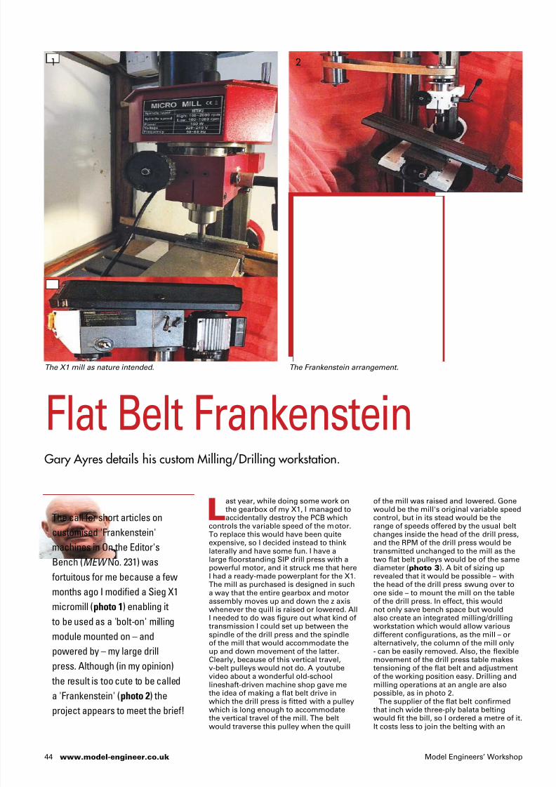
7/24/2019 Model Engineers_ Workshop - February 2016
http://slidepdf.com/reader/full/model-engineers-workshop-february-2016 45/77
44 www.model-engineer.co.uk Model Engineers’ Workshop
of the mill was raised and lowered. Gonewould be the mill's original variable speedcontrol, but in its stead would be therange of speeds offered by the usual beltchanges inside the head of the drill press,and the RPM of the drill press would be
transmitted unchanged to the mill as thetwo flat belt pulleys would be of the samediameter (photo 3). A bit of sizing uprevealed that it would be possible – withthe head of the drill press swung over toone side – to mount the mill on the tableof the drill press. In effect, this wouldnot only save bench space but wouldalso create an integrated milling/drillingworkstation which would allow variousdifferent configurations, as the mill – oralternatively, the column of the mill only- can be easily removed. Also, the flexiblemovement of the drill press table makestensioning of the flat belt and adjustmentof the working position easy. Drilling andmilling operations at an angle are alsopossible, as in photo 2.
The supplier of the flat belt confirmedthat inch wide three-ply balata beltingwould fit the bill, so I ordered a metre of it.It costs less to join the belting with an
Last year, while doing some work onthe gearbox of my X1, I managed toaccidentally destroy the PCB which
controls the variable speed of the motor.To replace this would have been quiteexpensive, so I decided instead to think
laterally and have some fun. I have alarge floorstanding SIP drill press with apowerful motor, and it struck me that hereI had a ready-made powerplant for the X1.The mill as purchased is designed in sucha way that the entire gearbox and motorassembly moves up and down the z axiswhenever the quill is raised or lowered. AllI needed to do was figure out what kind oftransmission I could set up between thespindle of the drill press and the spindleof the mill that would accommodate theup and down movement of the latter.Clearly, because of this vertical travel,v-belt pulleys would not do. A youtubevideo about a wonderful old-schoollineshaft-driven machine shop gave methe idea of making a flat belt drive inwhich the drill press is fitted with a pulleywhich is long enough to accommodatethe vertical travel of the mill. The beltwould traverse this pulley when the quill
Flat Belt FrankensteinGary Ayres details his custom Milling/Drilling workstation.
1 2
The X1 mill as nature intended. The Frankenstein arrangement.
The call for short articles on
customised 'Frankenstein'
machines in On the Editor'sBench (MEW No. 231) was
fortuitous for me because a few
months ago I modified a Sieg X1
micromill (photo 1) enabling it
to be used as a 'bolt-on' milling
module mounted on – and
powered by – my large drill
press. Although (in my opinion)
the result is too cute to be called
a 'Frankenstein' (photo 2) the
project appears to meet the brief!

7/24/2019 Model Engineers_ Workshop - February 2016
http://slidepdf.com/reader/full/model-engineers-workshop-february-2016 46/77
45
Frankenstein Mill
February 2016
'alligator' style metal clip than it does tohave the supplier make a seamless join. Iwanted to keep the project as economicalas possible, so I opted for this solution (Ialso quite liked the idea of using a clip).However, he advised me that this wouldideally require the pulleys to be made ofsteel rather than aluminium as the clipwould be likely to erode the surface of thesofter metal over time. I also learned thatthe pulleys would have to be a minimumof 3 inches in diameter as the sharpercurves created by smaller pulleys woulddelaminate the belt.
For the mill, a pulley of 3 inch diameterand 1 inch width was turned from brightmild steel (photo 4). Using a dividingsetup on the drill press, six holes weredrilled through it in order to reduce itsweight, and a keyway was cut toaccommodate the existing key. Makingthis pulley was quite a mission, but interms of design it was fairlystraightforward. The drive pulley on thedrill press required a bit more thought.What I didn't want was to have the pulley
fall out of the drill when in use as theconsequences of that could be disastrous.After considering options, I decided to usewhat was already there – the drill chuck –as the core of the pulley. A piece of steelpipe was used to form an outer sleeve forthe pulley. Due to a mismatch ofdiameters, it was necessary to make aninner sleeve as a spacer, for which I used apiece of aluminium pipe bored to size.Sliding fits were created between thechuck and the two sleeves. A collar wasmade to fit over the end of the quill of thedrill press, again using steel pipe shimmedwith aluminium. This was then drilled withthree equidistant holes which were tappedM6 to accept stainless steel cap-headscrews. When the pulley is in positionthese screws are tightened into threelocating indentations which were spottedinto the nose of the spindle of the drillpress. The screws provide most of thedrive which is transmitted from therotating drill spindle, and they anchor thepulley to the spindle to hold it in position.
For the top end cap of the pulley, a circlewas cut from steel plate and the centre ofthis was bored to the diameter of thecollar. The outer sleeve, the top end capand the collar were then silver solderedtogether to form the main assembly. Thebottom end cap is not fixed to the pulley,enabling installation of the pulley into the
drill press by sliding the drill chuck upthrough the pulley and inserting the shankinto the drill in the normal way. A shortpiece of round steel bar with a threadedend – having already been secured in thechuck – protrudes down through a hole inthe bottom end cap which is then locked inplace with two nuts and a washer. Acircular locating groove was milled in theupper side of the bottom end cap toensure concentricity with the rest of theassembly. Photograph 5 shows acut-away view (created using Gimp opensource image editing software) of thedrive pulley assembly in situ on the drill.The completed drive delivers plenty oftorque as transmitted from the drill press,and the flat belt grips the pulleys well.
The castings of the mill and the front partof the head of the drill press wereoriginally red in colour. In order to put myown stamp on the workstation while
the effect of the column 'piercing' thehardwood shelf, the column was madelonger than the height of the shelf. The topof the column was then turned down andthreaded M6. The narrow threaded portionof the column was passed through a smallhole in the shelf, and the finial – which wasdrilled and tapped – was screwed on to it.
I look forward to further exploration ofthe capabilities of my 'Frankenstein'milling/drilling workstation. ■
ensuring that the two componentmachines remained visually integrated, Ipainted these parts white - not aparticularly 'Frankenstein' colour, andarguably not a particularly practical coloureither. I like it though!
One of my concerns about this projectwas the possibility that the table of the drillpress – although heavy - would not providea stable enough base for the mill and thatthis may result in excessive vibration.However, this is not as bad as I expected itto be, and I anticipate that the device willbe able to perform a good range of usefuloperations. My sense is that what has beensacrificed in terms of a rock-solid setup willbe compensated for by convenience,flexibility and space-saving. In any case,early indications are good.
The small example shown in photo 6illustrates a piece of work done with themilling table set at an angle (as in photo 2).This is a finial on one of the aluminiumshelf support columns for a built-in TV andmedia unit. The angled cut at the top wasmade using a slitting saw in the mill withthe workpiece held in a three-jaw chuckmounted on a locked rotary table fixed tothe tilted table of the mill. In order to create
3
5
4
6
Flat belt pulleys and balata belt.
Cutaway showing how the drive pulley fitsover a drill chuck.
The hefty 3-inch driven pulley.
A shelf support finished on the Frankenstein Mill.

7/24/2019 Model Engineers_ Workshop - February 2016
http://slidepdf.com/reader/full/model-engineers-workshop-february-2016 47/77
46 www.model-engineer.co.uk Model Engineers’ Workshop
If you have got this far into this articleand you are in the 'over my deadbody' camp when it comes to digital
technology I hope to entice you to read on.The smart phone is a really easy way in toall aspects of the internet. This is because
the operating system has to be reallyintuitive to use since just about everythingis done using the touch screen. Manysmart phones can be instructed by voiceor handwriting too, so there is no need tothink you will be a slave to the keyboard.At this point I would like to mention thatI use the term 'mobile phone' to meansmart phone or tablet. See photos 1 and2 for the phones mentioned in this article.
It is perhaps worth reflecting how fartechnology has moved in my working life.As I was entering my teens I watched theoriginal Star Trek series with thecommunicator devices that allowedconversation between characters indifferent places, and then went tocomputer studies lessons where themachines we used were programmed withpunched cards. It was a task to get suchmachines to add up and the communicatorof Star Trek looked to be science fiction
possibly life saver when assembly timecomes weeks/months later.
As time went on phones arrived withmore and more powerful cameras. Thesewere used to magnify photos ofcomponents to help me analyse problems.
Has a tool tip frittered? No messing abouttrying to get a magnifier (and my head)into a position to inspect the tool - justphotograph it and enlarge it on-screen.Looking inside a dark space anywhereinside a machine, even right at the back ofthe bench where you thought that part haddropped. Out comes the phone – 'click' - afew shots with the flash on and then scourthe photos for your elusive quarry! Nomoving stuff around, contorting to getyourself in, banging head etc. All of thephotographs for this article were taken ona mobile phone: if I am doing a job thatcould make a good article, out comes thephone to take some shots of the set-upsready for a later write-up.
Much of my work these days involvesmaking or repairing parts for vintage cars(c. 1930). Clearly it is not always practicalto bring the part-assembled car to myworkshop to machine the mating part. So
that would never come to pass in mylifetime. How wrong I was! The smartphone is the embodiment of the Star Trekcommunicator, on steroids! It is apowerful computer with a camera andother sensor technology built into a
package handy for your pocket: it cansecrete its way easily into your workshopwhere the sensors can be made to work asinstruments and tools for all sorts of tasks.
Where did it start?About ten years ago I was looking fora new mobile phone. My daughter gotinvolved and encouraged me to buya phone with a camera. I was reallyskeptical about the use I would make ofsuch a device built into the phone. AgainI was wrong: soon I found myself usingthe camera as a powerful and accuratenote-taking device, photographingtooling and materials at shows and inshops for later reference. Then the directworkshop applications started to creep in.Photographing an assembly before andduring dismantling, particularly wiringinside machines can be a real time- and
The mobile ‘smart’ phoneas a workshop tool?Howard Jennings has a play with new technology.
1
2
My Nokia phone showing appsand features in this article.
My wife’s Samsung phone.
I rate tools on how often you
find yourself using them. To my
surprise I have found my mobile
'smart phone' becoming an
integral part of my workshop
activities, finding it in my hand
more and more. I decided to
pen this article (on my phone
of course) to give readers a
heads-up on how I am using
my phone and where I think the
technology is going. This is not
a comprehensive round-up of
the market or the technology.
Writing such an article would bea massive task and the market
for these devices moves so fast
that the information would be out
of date in a few months.

7/24/2019 Model Engineers_ Workshop - February 2016
http://slidepdf.com/reader/full/model-engineers-workshop-february-2016 48/77
›
47
Smartphones in the Shop
February 2016
the next best thing is to photograph themating assembly, sometimes with a rulepositioned in the shot and or someaccurate caliper measurements. This helpsme to check or infer dimensions later, thezoom on the camera being particularlyuseful. This approach is nearly as good asa drawing and takes far less time. Plus thephone gives me direct access to theinternet: I can look up technicalinformation instantly and check shops formaterials and tooling while I am involvedin the job. And yes, I can phone suppliersor order directly online.
AppsI am trying hard not to sound like acomputer magazine. However, I cannotavoid this shortened form of the wordapplication. So far I have looked at usesfor the smart phone in the workshop usingthe 'out of the box' features. Things getmore interesting when we start to lookat the apps available for smart phones.Whilst there are millions of apps formobile phones, only a small number havedirect relevance to workshop activities.
Photo 1 shows the apps I use arrangedseparately on the screen. I use the photolight almost daily. For those unfamiliarwith the possibilities offered by apps, thisone allows the camera flash light to stayon continuously for illumination. I amforever finding the need to look into adark recess inside a part I am making and
it is invaluable when something drops onthe floor and rolls into a dark area. Ialways have my phone on my person forcommunication so it is a torch ready togo, (usually) fully charged and perfectlyto hand.
More recently I have found a magnifierapp useful. I had to try out one or twooptions to get the right functionality but thebest I've found feels very similar to using amagnifying glass with the added benefit ofintuitive adjustable magnification. At thevery least it is good for reading obscuretext/small print/grubby two-year-oldpencilled notes! And better still, so far allthe apps I've mentioned are free!
Drawing AppYes, you can get the equivalent of a CADsystem working on a mobile phone! Okay,it doesn't have the full functionality of a
and the plan for the next job is on its way!Photograph 3 is actually a screen shotfrom ArchiTech showing a part (blacked in)that I am pondering making for my millingmachine. Note some phones like theSamsung (photo 2) have a built in drawingsystem using a separate hand stylus.Photograph 4 shows a sketch done usingthe stylus-based sketching system builtinto a Samsung Galaxy Note phone.
Clinometer appIf you've handled a smart phone, youwill know that they contain sensors thatenable the screen image to be reorientedas you rotate it. These are utilised in amore sophisticated type of app to allowyou to measure angles quickly and easilyusing a phone. You can get some ideaof how accurate it is from photo 5. Thephone (showing the clinometer app) andthe decent, metre-long level are up against
2D CAD system but this isn't some kiddies'drawing plaything that puts coloured linesand shapes on the screen. The one I use iscalled ArchiTech. All the drawing is donewith the end of your finger, even if youhave big fingers (as I have). You selectthe line type (solid, dashed etc) and thencontrol the length, width and angle withyour finger using the screen icons thatappear around the line. All of the featureswork in a similar way to this. The app isdesigned for architectural plan drawing butcan be persuaded to produce engineeringdrawings at a 'looks much moreprofessional than hand sketching' level.And even better it will allow you to drawon an image - photograph a componentand then draw on top of it to show howa modification or addition will look. Thisis like taking your workshop with you inyour pocket! Sitting around on the busor train, in any waiting room or on yourmother-in-law's sofa out comes the phone
3
5
4
Milling machine part sketch.
Clinometer app.
Sketch using the Samsung.
Yes, you can get
the equivalent of a
CAD system working on
a mobile phone! Okay,
it doesn't have the full
functionality of a 2D CAD
system but this isn't some
kiddies' drawing plaything
that puts coloured lines
and shapes on the screen.

7/24/2019 Model Engineers_ Workshop - February 2016
http://slidepdf.com/reader/full/model-engineers-workshop-february-2016 49/77
48 www.model-engineer.co.uk Model Engineers’ Workshop
each other on the same surface. There isan in-built calibration within the software
that seems to work by ‘splitting thedifference’ when the phone is rotated ona reasonable surface as instructed by theapp. You will note that this app claims tobe able to measure angles to within ± 0.1degrees depending on the phone quality.As I write I have no reason to doubt thisaccuracy on my phone. This app also actsa surface level (see photo 6), thoughsince the camera lens stands proud ofthe rear of my phone, I have to be a littlecareful when using the app for this.
Market realityAt this point I must just throw a bit of coldwater reality in to this article mainly dueto the mobile phone market. In comingto write this article I took account of myown smart phone, which is a Nokia Lumia1520 (photo 1) that uses the MicrosoftWindows operating system: it has a largescreen placing it halfway between being aphone and being a tablet (a 'phablet', yesI hate it too).
Those of you who remember the 'goodold days' of the VHS/ Betamax videoplayers will not be surprised to learn thatthere are competing smart phoneoperating systems, the two biggest kids inthe playground being Apple's iOS andGoogle's Android. There are literallymillions of apps available for both iOS and
Android through their respective appstores, but it seems most of theengineering apps are built for Android.Darn it! I chose the wrong system for theright reasons! Let me explain - Nokia isnow owned by Microsoft which is great forcompatibility with the Windows operatingsystem on my computer. However,Microsoft entered the smart phone marketlate and has therefore had to try to get apiece of the action from the other twogiants. Unfortunately, it has fallen badly atthe apps fence because there are notenough users for the app developers to beinterested. It seems that something willhave to change to open up the market andthere is strong talk that Windows willeventually accept Android apps. This is theapproach taken by Blackberry, rememberthem? I had a Blackberry myself up until ayear ago. Five years ago Blackberry wouldhave featured strongly in an article like
The futureI see the apps improving and more beingadded. However, the addition of extraequipment to increase the functionality isstarting to happen. You may have seenapps that analyse car electronic controlsystems, working through a deviceplugged into the car and a Bluetooth link. Isee considerable possibilities here for thesmart phone in the workshop.
Buy a phoneIf you are looking to upgrade or may beenter the market don't buy on impulse.Take a long look, ask around, look online; ifyou can go in a shop at quiet time and seephones demonstrated so much the better.I notice a trend towards smart phoneshaving better forward cameras (lookingout of the screen for ‘selfies’) than thecameras for taking pictures away from thescreen. In my view such a phone would belimited in the workshop. You will find thebigger the screen and more 'mega pixels'the cameras have the more you pay.
Just because these devices are sold asphones there is no need to operate themas such – you could think of them as verysmall computers or even as semi-virtualmultitools. If your phone or tablet willonly get used in the house and workshoplook at using WiFi only. If you are in luckit might be possible to hitch on to a freelocal WiFi if you live near one or do a dealwith your neighbour to use theirs.
FinallyI hope you have found this quick look atthe mobile smart phone in the workshophas opened up possibilities you werenot aware of. I have deliberately notmentioned all the communication toolsthat such phones offer: SMS (texts), email,skype, facebook, twitter, and good oldspeech telephone! Surely even the mostdie-hard anti computer workshop hermitcannot ignore the potential these phonedevices offer. ■
this but no more, since their poor appshowing (amongst other problems)caused big issues and their popularity tooka nosedive. Things move fast in thismarket - I am conscious this article maywell be out of date in under a year.
Samsung to the rescueAs luck would have it my wife also has
a large screen mobile phone; a SamsungGalaxy note 2 (photo 2) that uses theAndroid operating system. She kindlyallowed me to look around at some apps.I can therefore report that Androidappears to have more engineering appsand there are more CAD drawing systemsavailable. The engineering apps aremainly aimed at engineering studentsand feature a range of automaticcomputations but I can see some of youbeing able to pick out functions fromapps like this to assist projects. As for theCAD drawing systems on Android mostof them seem to be CAD viewers butsome seem to be capable of modifyingdrawings that are saved as DXF files.
Unfortunately I haven’t managed to lay
hands on an Apple iPhone for this article.However, the competition with Android isso fierce that I would expect to find anequivalent of any of the apps I havementioned on the Apple system. It maywell be that the Apple system is better onsome engineering apps as apple softwareis the ‘standard’ for graphics work.
Other handy appsIn preparing this article I did a bit moreresearch to see what I could find that maybe useful in the workshop. I haven’t gota lot of experience with these apps but Ifeel they are worth a mention. You willsee on photo 1 a tile button to start a unitconverter. I have noticed quite a few appslike this. I am giving this one a try, I don’tfind myself doing a lot of unit conversionbut my experience is that conversionsoften crop up out of nowhere. Anotherapp you may notice on Photo 1 that tookmy eye is a decibel meter. I don't do alot of really noisy stuff but handy just tocheck up on the noise level on jobs thatmay be a problem with the neighbours.I am sure you have spotted the fractioncalculator on photo 1 as well, anotherapp that is handy to have around in theimperial measuring system.
I was particularly interested in the app inphoto 7. I was originally trained using SI
units since my apprenticeship was with afirm that worked almost entirely inimperial. My subsequent career was allwith companies using SI units. Mybusiness now involves cars from the1930’s, all imperial measurements.Switching between the two systems is aregular part of my workshop life. However,I like using metric measurements on somemachining operations because of theappearance of the sizes. Compare 1.125and 1.25 inches with 28.575 and 31.75 mm:the significant difference in the numbersand sequence between the sizes I findhelps to prevent mistakes, particularlywith an operation like coordinate drilling.This app could be a massive help. Notealso the nifty feature of finding the nearestfractional inch size straight from a metricto imperial conversion. I do have a ‘Zeus’book that this app does not replace - I seethis app as a useful co-player.
7 Metricimperialconverterapp.
6 Clinometersurface level.

7/24/2019 Model Engineers_ Workshop - February 2016
http://slidepdf.com/reader/full/model-engineers-workshop-february-2016 50/77
M a d e i n E n g l a n d
All metal
CNC machinedand laser cut
components
Armortek all metal kits are built to last. Constructed primarily of aluminium and steel they
are supplied fully machined for bolt together assembly.
Kompact Kit
By Armortek EASY TO ASSEMBLE SCALE ALL METAL KITS
Price £498.00 inc. VAT (+ p&p)
• Working elevation and slew
• Moulded rubber tyres
• Complete with foldaway ground ring
• Gun sight
• Fasteners
• Over 600 rivet details
• Simple exploded
view instructions
Two Superb Metal Models
25 PDR.
Field Gun
25 PDR.
Ammunition
Limber
Buy your kit online - www.kompactkit.co.uk
FAST DELIVERY
• Working rear doors• Moulded rubber tyres
• Complete with tow gear
• Ideal with 25 PDR. Field Gun
• Fasteners
• Over 200 Rivet details
• Simple exploded view instructions
The 25 PDR. Field Gun and Ammunition LimberPrice £294.00 inc. VAT (+p&p)
All metal
CNC machinedand laser cutcomponents

7/24/2019 Model Engineers_ Workshop - February 2016
http://slidepdf.com/reader/full/model-engineers-workshop-february-2016 51/77
50 www.model-engineer.co.uk Model Engineers’ Workshop
The unit can now be fitted to the lathe.Supporting the drive unit, screw the leadscrew back into the cross slide nut. If thepower unit is available the cleaned andlubricated lead screw can be driven inunder power, much easier. Attach the
drive unit to the cross slide with the twocap head screws removed above. Theposition for the limit stop cam can now befound and the cam fitted to the front of thesaddle. All that remains is to attach thelead to the side of the cross slide with theconduit (fig.13 and photo 8). The detailsof the conduit are for the ML7R lathe andmay be different for other models/lathes.
Electrical componentsRefer to fig. 14. There are one or twoelectrical components for which nocommercial equivalent could be found,so I finished up making them myself. Forthe two small tag boards I used some tagswhich are called ‘Turret Lugs’ which I hadon hand. Again I could not find a supplierso I have included a drawing of a brasstag that will do and whilst rather fiddly isnot too bad to make, and only eight are
This is a good time to check the settingsof the slide gib strip as it is only possibleto set it up correctly when the lead screwis removed and the slide can be movedfromv end to end by hand, after cleaningand oiling.
Slide the larger of the bevel gears, 32teeth, onto the lead screw extension,ensuring it is the right way round, see fig.1, and lightly lock in place over the flat cutout section of extension. Screw the ¼ inchBSF end of the lead screw fully into the 3 ⁄ 8inch end of the extension and, lightlygripping the lead screw (vice with soft
jaws), and using the spanner flats tightenthe extension fully. Lightly oil theextension and carefully feed the ¼ BSFend through the two bushes from the backof the front plate. Take care that the wiresin the chassis area are not trapped and aredirected well clear of mechanicalcomponents. Slacken the screws retainingthe two bevel gears and when the gearleaver is locked in the fully up position thegears can be adjusted for smooth running.The latch stop screw may also needadjusting at this time. Fit the case withfour 6BA screws.
Mechanical assemblyPlease note, the electrical components inthe body area need to be fitted before themechanical assembly can take place, seethe next section. Remove the cross slidehandle and dial from the lathe. Remove the
two retaining screws and remove the crossslide bracket from the slide. Unscrew thelead screw from the nut in the cross slide.
Myford ML7R
Power Cross SlideKeith Wraight answers a perennial question – can power cross feed be fitted to an ML7R?
The completed unit ready for painting.
Standing at the lathe, a Myford
7R, taking a few thou off the front
of a face plate I was thinking
how nice it would be to have a
Myford super 7 machine with
power cross feed.
There seemed no prospect of a
mechanical modification as the
Super 7’s saddle and cross slide
is completely different to that
on the 7R and it would be a very
expensive proposition. However,
not wanting to be beaten I then
turned to thinking about an
electrically powered approach
and this seemed to be a much
more promising proposition.
Part 3
8
Wiring attached to the unit.

7/24/2019 Model Engineers_ Workshop - February 2016
http://slidepdf.com/reader/full/model-engineers-workshop-february-2016 52/77
›
10.500
9.875
9.250
8.375
7.625
6.750
6.000
5.250
4.500
2.000
0.375
3.875
7.250
10.188
0.124
Ø0.250
0 .
5 0 0
Conduit Cable
1.250
0 .
2 5 0
Ø0.40
Ø0.25
Ø0.25
Ø0.120 Ø0.080
Ø0.045
Ø0.156
Ø0.120
Ø0.188
Ø0.078
Ø0.086
0.1560.063
0.1250.125
0.125 0 . 2 5 6
0 .
1
Ø0.082
Ø0.082
0.25
0.25
Ø0.076x 4
0.05
0.16 0.1630.700
0 . 7 0 0
0.375
0 . 3 8
0 . 6 1
1 . 0 6
1 . 2 8
1 . 4 4
0 . 8 3
Plastic Button
Ø0.25
Ø0.4375 x 40
Ø0.63
Ø0.20 Ø0.40
Polish cap
Polish caps
BezelsMat’l: Stainless steel
Tag BoardsMat’l: 0.05in insulation board
Electrical components
Ø0.3125 x 40
0.220.12
LED
Ø0.44
0 .
2 9
0 . 3 1
r0.03
90˚ 90˚
0.03
51
ML7 Cross Feed
February 2016
Fig. 13
Fig. 14

7/24/2019 Model Engineers_ Workshop - February 2016
http://slidepdf.com/reader/full/model-engineers-workshop-february-2016 53/77
Circuit Diagram
Power Supply
L
E
N
5A
SW1
Filter
9V
9V
+
+
-D1
C1
6A
RL1/1
PCB
PWM Unit
Speed/Direction
Cable
RL1
Start SW2Start
RL1/2 R1 470Ω
R2 200Ω
LED
Motor
Slide Unit
+
SW3
Stop Switch Limit Switch
SW4
2 x 8BA
Microswitch Bracket
Cable Gland
0.039
0.125
Microswitch
0.481
0.940
0.399
Soft solder
0 . 2
8 9
0 . 4
1 4
Ø0.087
Ø0.500
Ø0.085
Ø0.065
Ø0.400
0.156
0.688
0.250
0.438
Ø 0 . 3
7 5
Ø 0 . 1
8 8
Ø 0 . 3
5 0
52 www.model-engineer.co.uk Model Engineers’ Workshop
required for the two tag boards. The longtag strip is attached to the body by two8BA screws with a plastic strip and twoplastic washers to insulate and space thetag board from the body (photo 9). It willbe found much easier when you cometo assemble the small square tag boardto the body if the spacers fitted behindthe board are attached to it. The spacerdrawing shows a tubular rivet formed onone end of the spacer for this purpose.The next item is a bracket used to mountthe limit stop micro switch. The bracket
consists of a short length of brass anglewith two captive 8BA countersunk screws(fig.15 and photo 10). The two screwheads are soldered to the bracket, softsolder being plenty strong enough here.The two micro switches, one with a rollerpart no. 78-2474 and one with a lever partno. 78-2468, are both from ‘Rapid electricalcomponents’, usual disclaimer. The switchwith the roller is used as a limit switchand the one with the lever as the switchelement of the stop switch fitted on thetop of the unit.
The electrical components can now bemounted on the chassis. Screw the twostainless steel bezels (fig.14) into the bodyfrom the outside, tight. Place the switchbutton in the larger of the bezels from theinside ad then screw the micro switch withthe leaver in place. Note: the lever mayneed adjusting (bending) slightly to makethe button operate correctly. Aftersoldering the components to the squaretag board; see circuit diagram, fig.16 andphoto 10. Screw the tag board in placewith two 8BA screws. Solder the link from
Fig. 15
Fig. 16

7/24/2019 Model Engineers_ Workshop - February 2016
http://slidepdf.com/reader/full/model-engineers-workshop-february-2016 54/77
›
0.375
Cable
To motor
Limit switch
SW2
Section B-B Section A-A
2.250
A B
A B
MicroswitchBracket
R1R2
SW1
Tag Board
LED Red
Stop Button
Stop Switch
Position Of Electrical Components
53
ML7 Cross Feed
February 2016
wiring and components fitted to the slideunit on the lathe which are connected to
the power supply by a four way cablewith a plug at the power supply end. Thecable is fed through the cable gland andsoldered to the four way tag stripmounted on the chassis see fig.7 andphoto 10. From the tag strip two wiresare connected direct too the motor andthe remaining two wires connect the twomicro switches. The two switches areconnected as normally closed and are inseries with the 200 ohm resistor R2.There is also an LED with its associated470 ohm current limiting resistorconnected across R2. Take care that thewires are routed as shown in thephotograph as they have to avoid othercomponents on assembly.
the tag board to the micro switch. Connecta short length of insulated wire (red inphotograph) to the tag board. Solderanother short length of insulated wire(grey in photograph) to the other endcontact of the micro switch. Connect the
two wires to the long tag board the greyone via the outside terminals of the microswitch with the roller which can now bemounted on the chassis as shown. Thecable gland of your choice can now befitted and the four way cable you havechosen can be feed through the gland andsoldered to the long tag strip as shown.The plug can be attached to the cable tofinish of the wiring of this unit. Pleasemake sure the wires are tucked well downinto the chassis as shown and will notinterfere with the mechanical operation.
The linear cam which operates the limitswitch is mounted on the front of the lathesaddle, is shown in fig.18 (overleaf). Withtwo 6BA/3mm screws. The location of the
cam is best left until the unit is mountedon the lathe and the position of the cam
can be ascertained, and the holes drilledand tapped for the screws in the front faceof the saddle.
Electrical detailsSee circuit diagram, fig.16. When thepower lead is connected to mains somecomponents inside the power supply unitwill have lethal voltages on them. Do notoperate the unit with the cover removed.If the builder does not feel competent toconstruct electrical components, you arestrongly recommended to seek assistancefrom someone who is.
The circuit diagram is split into twoparts. The first and simplest part is the
Fig. 17
9 10
Tag strips inside the body. The microswitch can be seen at right.
I have found the unit
very solid and extremely
useful since I fitted the
prototype to my machine.
I recommend the driveto anyone wanting an
interesting project with
a useful addition to your
lathe at the end.

7/24/2019 Model Engineers_ Workshop - February 2016
http://slidepdf.com/reader/full/model-engineers-workshop-february-2016 55/77
Limit Stop Face CamMat’l: Aluminium
Cross slide leadscrew nut
Phos. bronze strip
6BA adjuster
Locate on assy.
10BA csk. screw
0.63
0.25
0.25
0.25
0.25Ø0.125
Saddle
Block: 0.625 x 1 x 0.625
0.43
0.13
0.38
0 .
2 5
0 .
7 5
0 . 3
5
0 . 3
5
0 .
9 0
0 .
6 0
0 .
1 8
1 .
0 0
23.20˚
1.01
0.13
0.75
54 www.model-engineer.co.uk Model Engineers’ Workshop
Power Supply UnitSee photos 11, 12 and 13. The unitneeds to be housed in a metal case whichmust be earthed, for which I will not besupplying any mechanical drawings, as Iused a commercially available case. Thereare many ready-made cases you can chosefrom one of the suppliers listed at the endof the article. I used one from Radiospares(showing your age! They rebranded asRS Components in 1971! – Ed.) whichcan be seen in the photographs. Thepower supply unit contains an ON/OFFswitch SW1, a mains filter and a 9 volttransformer TR1 which with a bridgerectifier D1 and smoothing capacitor C1producing a 12 volts supply at up to 5amps DC for the motor. There is also a 5amp fuse in the mains supply socket. Thepower supply unit also contains relay RL1which has two changeover contacts, thepulse width modulation (PWM) moduleand a press button (press to break) switch.The PWM module is available from many
suppliers and in many types. The speedcontrol featured in a recent MEW couldbe used with a separate direction changeswitch. The one I chose controls both thespeed and direction of the motor with onerotary control that has a stop position atthe centre of its range, it is available fromMFA/Como Drills part no. 919D2PR, asalso is the motor which is part number970D471LN and comes ready fitted with a47:1 gear box, which combination I foundto give a usable range of speeds at thelead screw via the 2:1 bevel gears. Seephoto 14 for the complete assembledunit ready for mounting on the lathe.
Fig. 18
11
13
12
Power Supply Unit.
Transformerand PWM
module.
Inside the unit.

7/24/2019 Model Engineers_ Workshop - February 2016
http://slidepdf.com/reader/full/model-engineers-workshop-february-2016 56/77
55
ML7 Cross Feed
February 2016
Radio Spares www.rsonline.comRapid Components www.rapidonline.comMFA/COMO www.mfacomodrills.comHP Gears www.hpcgears.com
SUPPLIERS
lead screw turns freely in both directions.Check the limit switch again just to besure. Turn OFF the switch on the powersupply. Congratulations you now have aworking unit.
I have found the unit (photo 14) verysolid and extremely useful since I fitted theprototype to my machine. I recommend thedrive to anyone wanting an interestingproject with a useful addition to your latheat the end. Happy turning. ■
14
The completed unit.
OperationWith the mains power lead connectedto the power supply and the cable fromthe cross slide unit connected. Turn thegear lever anticlockwise to disengagethe drive from the lead screw. SwitchON the mains switch, the switch shouldlight up. Press and release the startswitch on the power supply. The relayRL1 will energise. Contacts RL1/2 willchange over connecting 12 volts positivevia. The two micro switches and R2 the200ohm resistor in the slide unit holdingRL1 ON. The voltage dropped acrossR2 is also applied to the LED and R 1and the LED will light. At the same timerelay contacts RL1/1 close and connect12volts to the P.W.M. unit and if therotary control on the P.W.M is set to runin either direction the motor will start,the lead screw will not turn as the bevelgears are not engaged. You can nowcheck the operation of the P.W.M. unit.Turn the rotary control fully anticlockwiseand the motor should run at full speedin one direction. Turn the control slowly
clockwise and the motor will slow downand stop when the rotary control iscentralised. Continue to turn the controlclockwise and the motor will start toturn in the opposite direction slowly atfirst and at full speed when the controlis at its stop. Check that both the microswitches stop the motor when operated.Check that if the lead screw is turnedby hand the limit switch SW4 operatesbefore the cross slide touches the saddle.Turn the rotary control back to the centreOFF position and the motor will stop. Itdoes not matter which way the motorturns as you will soon get used to whichway to turn the control. It is a simple
job if you feel you would rather it wasthe other way, simply reverse the wiresat the motor or the tag board. Now turnthe gear lever slowly clockwise until itlocks, the gears are now meshed and therotary control can be used to check the
Coming up in Issue 4527...
O n S al e 5t h
F e b r uar y • A Presentation ‘Egg-beater’ Drill
A beginner’s exercise in makingand fitting small parts
• Tyndale A small battery electric locomotive
• MEX Entry Forms and Information
•
A Model Shaping Machine• Track Repairs at Kinver

7/24/2019 Model Engineers_ Workshop - February 2016
http://slidepdf.com/reader/full/model-engineers-workshop-february-2016 57/77 www.emcomachinetools.co.uk
We regularly ship worldwide Please contact us for stock levels and more technical detail
All of our prices can be found on our web site:
GOL ®
matic M a s c h i n e n b a u
• Table – 500 x 150mm
•Z axis – 280mm•Speed – 140-3000 rpm•Power – 1.4 KW
• Table – 500 x 200mm•Z axis – 280mm •Speed – 140- 3000 rpm •Power – 1.4 KW
• Table – 450 x 160mm•Z axis – 320mm
•Speed – 365-1800 rpm•Power – 250 W
•Centres – 500mm •Centre Height – 200mm•Speed – 100-1800 rpm •Power – 0.75 HP • Table –
420 x 160mm•Z axis – 300mm
•Speed – 100-3000 rpm
•Power – 1.5 KW
•Centres – 600mm•Centre Height – 135mm•Speed – 30-2300 rpm•Power – 1.4 KW
Precision European made machine tools for the discerning engineer!
MORE MACHINES AND ACCESSORIES ON LINE
PRO Machine Tools Ltd.
17 Station Road Business Park, Barnack,Stamford, Lincolnshire PE9 3DW
tel: 01780 740956 • fax: 01780 740957email: [email protected]
•Centres – 300mm •Centre Height – 52mm •Speed – 250-2000 rpm •Power – 250 W
TECOMill
VF400
CerianiMill
David403
TECO Lathe MD 200
Wabeco CNC MillCC F1410E
WabecoMill
F1210E
t
ePlease conta
MOR
•Centre Distance – 600mm•Centre Height – 135mm•Speed – 30–2300 rpm
•NCCAD •Power – 1.4 KW
Wabeco
CNC Lathe CC D6000E
Our machines suit the discerning hobbyist as well as blue chip industry
Wabeco LatheD6000E
Ceriani Lathe David 203
ACCESSORIESLathe Chucks, Drill Chucks, Tipped
Tools, Boring Bars, QCTP, HSS Tools,
End Mills, Slot Drills, Machine Vices,
Clamping Sets, Slitting Saws, Arbors,
Boring Heads, Radius Mills, DROs,
Rotary Table, CNC fits, Collet Chucks,Collet Sets, Flanges, Face Mills,
Shell Mills and Much More...
warrantyarr 5year
LINE
– - •Po er –
p n us ry
warrantywarr 5year
warrantywarr 5year
warrantywarr 5year

7/24/2019 Model Engineers_ Workshop - February 2016
http://slidepdf.com/reader/full/model-engineers-workshop-february-2016 58/77
›
57February 2016
I had a dreamIn my (limited) experience, the Hobbymat
lathe is capable of quite demandingturning operations for its size but ispretty hopeless when it comes to milling.The limited travel of the slides severelyrestricts the size of work piece and,more critically, the ‘D’ shaped bed is notsufficiently rigid to allow anything butvery light cuts. I have been able to flycut fairly large chunks of aluminium byresorting to some radical work-holdingmethods but machining has always beenpainfully slow. Consequently, a millingmachine has been on my wish list sincemy very first attempt; however, I havenever been able to justify the cost forthe limited amount of use, continuing tostruggle with the lathe. I’ve had varioushare-brained ideas about building my ownmilling attachment for the lathe but whenthought through, the answer always camedown to ‘not with the Hobbymat’. I knowthat drill presses have been converted forlight milling by other home machinists buta machine of sufficient rigidity and qualityof manufacture would probably also be anexpensive route once the cost of the co-ordinate table is added. Nevertheless, thisremained an option if the right drill camealong at the right price.
A dream comes true?The company I worked for until retirement
had a policy of offering surplus equipmentfor sale to staff instead of just scrappingeverything that had been replaced.Items were generally either obsoleteor faulty and could range from officefurniture, through computers, electronictest equipment to, very occasionally,mechanical workshop equipment. Sealedbids were required and, judging by thenumber of failed bids I submitted over theyears, the ‘rubbish’ on offer could makequite high prices. One such sale includedan ancient but very sturdy looking PollardCorona bench drill with three phasemotor. This intrigued me because thequill/spindle housing is supported by acast bracket sliding on flat ways. A cursoryexamination revealed no apparent defectsso I considered it to be worth a fiver to meand placed my bid.
My bid was successful because,apparently, it was the only one; I can only
A closer lookMy purchase remained in its disassembledstate in a corner of the garage for a longtime before I found the time to investigateit properly. From the limited informationI had gleaned from internet forums, Iexpected the spindle to be hollow witha Morse taper; what I found came assomething of a disappointment andshattered my dream of using it for milling.
There was no sign of a draw bar or anyother retaining arrangement at the top ofthe spindle and the solid shaft seemedquite slender. Removing the chuckrevealed a Jacobs taper, subsequentlymeasured and determined to be a ‘2’. Atthis early stage, I conceded defeat butdecided to replace the ½ hp motor with asingle phase type anyway, so that I wouldat least have a bench drill at last.
A search on ebay found an abundance ofmotors of all sizes and ages, but I settledon a used Brook ¾ hp at the ‘buy it now’price of £25. Lack of time intervened againand the motor gathered dust alongside itsnew home for a considerable time before Imanaged even to check that it worked. I didnotice a few minor problems that wouldneed to be resolved: The replacementmotor shaft was smaller in diameter thanthe original; the new motor was larger indiameter and length than the original and
presume that other bidders had beendeterred by the three phase motor, or the
weight, or the age, or something else thatI hadn’t noticed. I had to dismantle myprize in order to move it but it easilybroke down into three (just) manageablepieces. The internet didn’t reveal muchuseful information other than praise for agood old piece of British engineering.The company, of course, has long sincegone, having been set up in 1920 byFrederick Pollard when he left Jones andShipman (a company which he also cofounded). The company made high-speeddrilling machines, often ganged togetherto provide up to six spindles. Thehigh-speed drilling capability is borne outby the maximum speed of my example,of 6,050rpm, and the very small chuck(5 ⁄ 16 inch) for the size of the machine.The machine, as acquired, is shown inphoto 2.
An Old Bench Drill
Adapted for MillingNot being able to justify the expense of a ‘proper’milling machine, Alan Wain took a cheaper butmore rewarding route by adapting a sturdy pieceof good old British engineering to take on the role.
2
1
Bench drill as acquired.
The adapted bench drill.

7/24/2019 Model Engineers_ Workshop - February 2016
http://slidepdf.com/reader/full/model-engineers-workshop-february-2016 59/77
Motor
shaft
New key
Split sleeve
Pulley boss
58 www.model-engineer.co.uk Model Engineers’ Workshop
the mounting holes were spaceddifferently. These differences were not
entirely surprising and I had anticipatedmaking an adapter from 12mm aluminiumplate that I had put aside for the purpose.Oh well, perhaps another day?
Making a startRetirement brought the time needed tocatch up on long forgotten (or ignored)projects and I had really become tiredof tripping over, or having to move, thispile of cast iron. First of all, I prepared apedestal for the machine. This is actuallya four-drawer cabinet, in solid mahogany,that originally supported one end of alaboratory bench where I worked (yes,obtained in an earlier ‘staff sale’). My latheis mounted on 40mm kitchen worktopacross two of these, well screwed togetherand fitted with adjustable feet for levelling.A similar arrangement was prepared forthe Pollard but also with castors beneaththat can be jacked clear of the floor by theadjustable feet. There isn’t much groundclearance but it does make the machinemoveable without having to be dismantled.The Pollard was assembled onto thispedestal, minus the motor, so that it couldbe moved for all round access.
After some careful measurement, itbecame clear that simply using an adapterplate would not work, so I resorted toturning around the motor mounting ‘foot’,
leaving room for a second but narrowerfoot with just two mounting holes. Makingthe extra foot, and drilling and tapping twoextra holes in the motor casing didn’tseem too onerous a task; or was it?
The additional foot was made from alength of 25 x 50mm aluminium ofunknown grade. With not a little difficulty,the work was marked out and attentionturned to removing metal. Believing thathand working was my only option for this200mm long part, I set to with thehacksaw, cutting down almost to themarked arc near the centre and thenbreaking out the pieces with a chisel untilenough metal had been removed to allowcutting sideways with the saw. I thoughtthe sawing was hard work but when Istarted filing, my heart sank! Filing out thisprofile across 50mm was going to take along, long time. Time for some furtherthought.
The rest of the foot was completed bysaw and file apart from milling and drilling
the angled pockets and holes for attachingto the motor case. This was accomplishedby clamping to a bracket on the swivelledtop slide to achieve the correct angle, asshown in photo 4. When offered up to themotor casing, it became evident that thefoot had a slight taper, not obvious untilchecked with a square. I believe this wascaused by lack of rigidity, allowing thewhole setup to be ‘pushed over’ by theplunge cutting method. I corrected theerror by taping decorators’ aluminiumoxide paper to the motor casing androtating the foot around it with pressurebiased towards the high side. This solvedthe initial problem but left the foot slightlylower than the existing one; a strip of thinsheet steel between the motor foot andthe mounting bracket on assembly madeup the difference, resulting in the drivebelt tracking well on the pulleys. Theremaining work to fit the motor was fairlystraight forward. A sleeve turned to fit thedrive pulley and bored to suit the smallermotor shaft diameter was split lengthwiseto the width of the key, and a deeper keymade from Gauge plate (fig. 1). I replacedthe internal three phase wiring and fitted ano-volt release switch from Farnell on a
One of the accessories with theHobbymat lathe is an angle plate for
mounting the top slide vertically for millingoperations. By fitting a rectangle ofaluminium plate to this, to vastly increasethe height, a pivot point could bepositioned above lathe centre height by theradius of the motor case, plus allowancefor half the milling cutter diameter. Ihoped, then, to be able to swing the workpiece on a bracket from this pivot andhence machine the radius; alright in theorybut would it work safely in practice?Various bits of metal were duly drilled,tapped and screwed together to form aswinging milling table. A fresh chunk of 25x 50 was screwed to this from below, at thepoints which would eventually become themounting holes. Having previously markedout the radius again and also set out equaldivisions above it, the bulk of the materialwas removed fairly easily by chain drilling.The work was swung to each hole positionin turn, before tightening up the pivot boltand clamping with an engineer’s clamp;the cross slide being locked throughout theexercise. The work had to be removedfrom the setup for final separation with ahacksaw but the task was accomplished farquicker, and with much neater results thansawing and chiselling produced on the firstattempt. To finish, rather than attemptingto swing the work around a milling cutter, Iused the same method as for the chaindrilling but only moving the work about
0.5mm or less each time before plungingthe cutter across the work. The methodproduced a finish with very small ridgesbut that was a small price to pay for thephysical effort saved! The only problemencountered during the machining was thecutter pulling out of the taper whenwithdrawing the work after a pass. I have aselection of imperial drills and millingcutters with no. 1 Morse taper shanks. Thedrills work well in the lathe using a 2 - to- 1 sleeve but the milling cutters have nomeans of being locked into the taper andtend to shake out. I overcame this problemby very carefully holding the cutter shankinto the headstock during everywithdrawal. I stress ‘very carefully’because I am attached to my fingers;fortunately, there is quite a long shankdown to the sharp bits. The final stages ofmilling the curved seat can be seen inphoto 3.
43
Setup for milling pockets and drilling mountingholes in the second foot.
Machining the additional motor foot.
Fig. 1
Pulley bore modification

7/24/2019 Model Engineers_ Workshop - February 2016
http://slidepdf.com/reader/full/model-engineers-workshop-february-2016 60/77
›
Bracket
Fine-feed and clutch housingbolted to bracket
Split bore for clamping ontoreturn spring tension adjuster
Bracket bottom plateincorporating down-feed lockbolted to underside of bracket
Bracket clamps to bottom of quillto hold down-feed lock shaft
Down-feedlock shaft
Split allows clampingaction onto down-feedlock shaft
Note: Clamping screws omitted for clarity
59
Mill from a Drill
February 2016
comprised a silver steel shaft parallelwith and firmly attached to the bottom of
the quill, with provision for clamping theshaft at the bracket.
I wanted to avoid the complication ofworking out gear ratios for a calibrateddown-feed, because a single turn of thedown-feed handle didn’t seem to producea logical travel of the quill. Instead, Iopted for the simpler solution of boltingon one of the low-cost digital readoutsreadily available. The bottom end of thiswould attach to the quill bracket holdingthe lock shaft.
I didn’t envisage problems in fitting aco-ordinate table and raising the column, sothe only real show-stoppers would be thechuck, fine-feed or down-feed lock; if I couldmake these aspects work satisfactorily, thenthe dream could become reality.
DesignMeasurements were duly taken and adrawing produced to test and juggle ideas.The general arrangement devised forattaching the bracket, fine-feed assemblyand down-feed lock is shown in fig. 2.
After a rummage through my ‘come inuseful one day’ collection, I found a coupleof two-speed gearboxes from Black &Decker hand-drills. When stripped, theseprovided a collection of gears and what Ibelieve are sintered phosphor bronzebushes. One of the gears, straight cut
rather than helical, seemed the rightphysical size to use as a worm gear for thefine-feed and mated reasonably snuglywith the thread of a 20 x 2mm pitch boltskewed by approximately three degrees.The fine-feed design evolved around thismatch and is shown as a longitudinalsection in fig. 3. The worm gear, screwedto a bobbin, is free to slide along a spindlealigned with the machine down-feedspindle, and is moved by the pin of a crankrunning in the bobbin groove. Two drivepins in the machine side of the worm gearengage corresponding holes in a tophat-shaped replacement for the returnspring cover, which also incorporates abearing for the clutch/worm gear spindle.This arrangement not only engages/ disengages the fine-feed with the down-feed spindle, but also brings the worm gearinto and out of mesh with the worm. Forthis to work smoothly, the worm carrier is
• A fine down-feed of the quill, preferablyretaining use of the coarse feed handlewhen required;
• Some means of locking the quill in anyposition;
• A means of measuring down-feed; • A co-ordinate table; • Raising the column to compensate for
the 125mm lost to the height of the co-ordinate table.
Although fundamental to milling, theco-ordinate table was deliberately leftnear the bottom of the list because thiswould be a major purchase and, thus far,none of my hard-earned cash had beenbadly-spent.
The first three requirements would needsome means of attaching them firmly tothe machine. This seemed implausiblebecause the castings have no flat surfaces.The only area that seemed suitable wasthe large knurled housing at the left end ofthe down-feed spindle (photo 5). This isfor adjusting the quill return springtension and is locked by a screw frombelow. When tried, this didn’t seem as if it
would move readily, so became a possiblestructure for attachment to.
Visible in the photo, at the end of theknurled housing, is a round plate coveringthe down feed return spring, pegged torotate with the spindle and retained by asingle screw in the centre. This, I decided,could be modified or replaced to effectdrive to the spindle from the left side,leaving the existing down-feed handleundisturbed. A fine feed could be appliedto the modified or replaced plate via aclutch of some type.
The first consideration of a down-feedlock was to use a clamp and pinch bolt onthe quill itself; however, such anarrangement would reduce the amount ofquill travel, and the affect on alignmentof clamping direct to the quill wasunknown but could possibly impartsideways pressure when clamping. Thesecond idea and the method adopted,
plate made to fit the existing switchhousing. First trials were encouraging and,by fitting the single phase motor, the threespindle speeds had reduced to calculatedspeeds of approximately 950, 1200 and3000rpm. At this stage I felt quite pleasedwith my purchase, and with myself, forhaving acquired an excellent bench drillfor a total outlay of around £40. The costincreased to around £60 after painting!
That dream againThe machine entered regular useimmediately and I often wonder how Iever managed without a bench drill. Themore I used it, the more my thoughtsreturned to my original idea; I felt sure itwould be sturdy enough for light milling,if only a milling chuck could be persuadedto stay on that short taper. It occurred tome that an axial screw through a chuckand into the spindle may be sufficient;it would be self-tightening and shouldprevent the chuck being shaken free fromthe taper. It would all depend on howhard it would be to drill the spindle. With
a drill chuck rigidly mounted verticallyunder the quill, I fed the arbour down ontoa small drill and, to my delight, it drilledvery easily. This was so encouraging thatI enlarged the drilled hole and tapped itfor an M5 countersunk socket screw. Now,what to fix onto it? I considered makinga milling chuck to Harold Hall’s designbut discounted the idea on the groundsof having to cut internal threads (I stillhaven’t plucked up the courage to try).Instead, I opted to buy a flange-mountedER32 collet chuck that I could use on thelathe and also, via an adapter, on thePollard. If the project failed for any otherreason, then at least I could still use thechuck on the lathe, therefore it would notbe wasted.
With the chuck problem solved, inprinciple, it was time to assess the otheressential requirements for milling, thesebeing:
5
Attachment site for fine-feed bracket.
Fig. 2
Exploded GA of down-feed lock,fine-feed housing and attachment bracket

7/24/2019 Model Engineers_ Workshop - February 2016
http://slidepdf.com/reader/full/model-engineers-workshop-february-2016 61/77
Existing down-feed spindle
Existing down-feedreturn spring housing
Aluminium plate bracket
Pinch bolt clamps bracketto return spring housing
Mild steel extended return springcover, incorporating brass spindlebearing
Inverted U-shaped saddle carrying wormspindle, fixed into transverse slot in housing,skewed by 3 degrees
Original cover securing screw
Steel plunger and springengages in/out detents
Phospor-bronze wormroll-pinned to spindle
Steel spindle roll-pinned to finedown-feed handwheel (not shown)
Silver steel clutch drive pins (x2)engage holes in re-designed cover
Worm gear (ex-B&D drill)screwed to clutchengagement spool
Clutch engagement bobbin
free to slide along shaftSilver steel clutch spindleglued into end cap
End cap screwedto housing
Engagement crank and leverwith two detent positions
Rectangular aluminiumhousing bored through
Brass crank bearing
15
3
Ø 1 0
Ø 4 . 7 Ø
5 5 . 4
5 5
5 7 i s h
657ish
Gear shaft 49 long Ø10 with9 long major turned to fit backplate
3 x Ø15
20 x Ø10
Ø20
Ø3
2 0
5
Ø16
2
3
9 20
Ø 1
4
Ø 1
8
Ø 1
0
38
2
2
5
Worm pitch 2mm
77
2 5
5
5
4
4
9
1 2 . 5
39
1 8 . 5
3˚ Oilite bushes
Small Oilite bush Front
2 5
15 3
Ø 1 0
Ø 4 . 7 Ø 5
5 . 4
Ø4
1111
Ø1.3 alignment pin holeSpot through from original
Drill 2 x Ø4on 22 PCD
Drill & c/s 3 x Ø3on 20 PCD
60 www.model-engineer.co.uk Model Engineers’ Workshop
Fig. 3
Longitudinal section of fine-feed
mechanism and clutch, shown engaged

7/24/2019 Model Engineers_ Workshop - February 2016
http://slidepdf.com/reader/full/model-engineers-workshop-february-2016 62/77
›
61
Mill from a Drill
February 2016
MT1/J2 mandrel for fit with engineer’sblue. With the taper finished, I marked thepositions of three equally-spaced tommybar holes before removing the work fromthe chuck and drilling them on the Pollard.The finished chuck, minus closing ring isshown in photo 7.
With the collet chuck fitted to the Pollardspindle, I checked it for run-out and felt
very smug at this being negligible. Theonly down-side I could see was the lengthof the chuck but I felt, at this stage, thatcontinuing with the fine-feed and down-feed lock would be worth the effort.
The bracket for the down-feed lock shaft Imade from half-inch steel plate but thefine-feed housing and main bracket arealuminium block and 12mm plate screwedtogether. The edges of plates forming thebracket were machined square in thefour-jaw on the lathe; a lot of care andpatience was exercised here because of thelarge overhang. The sizes of both steel andaluminium plates prevented them frombeing chucked to bore the internaldiameters for clamping to quill and returnspring housing. Instead, these holes weretrepanned and then bored to size usingcutters ground from round tool steelmounted in a steel block held in thefour-jaw as a makeshift boring head;tedious, but with care this arrangement didthe job; photo 8 shows the down-feed lockbottom bracket being bored to size. Thesacrificial plate that the work is mountedonto shows where the cutter has passedthrough. Note also in this photograph, thatthe work has already been drilled andreamed ½ inch for the silver steel down-feed lock shaft at bottom right.
am inherently lazy and didn’t bother.Although tedious, I devoted a long time tothis operation, rewarded by a TIR of prettywell zero everywhere, except that I foundmy budget priced collet is actually slightlybarrel-shaped, albeit by only 0.0005mm.The setting operation is shown in photo 6.
With the work piece chucked andsupported by the tailstock, the external
diameters were turned and the thread cutfor the closing ring. With the worksupported by my new fixed steady, Idrilled and bored the collet taper, firstparallel to 22mm diameter and full depth,then tapered until the correct size wasreached. ER32 collet chuck manufacture iswidely covered on the internet and I useda method described on one such site toascertain the correct fit and finished size tothe tapered bore, using engineer’s blue.The size is correct when a collet; insertedgently into the well-cleaned bore, willenter until the protruding diameter of thecollet measures 31mm at the face of thework. I used a 10-9 collet with the 10mmshank of an end mill inserted to preventinadvertent compression. With the workstill chucked and supported, I drilled andcountersunk for the M5 fixing screw.
With the collet end completed, I set upthe top slide to turn the Jacobs taper,using the same method as before but witha MT1/J2 mandrel between centres (yes, Ibought one). I then re-chucked the 20mmmandrel used to set up the collet taper,and skimmed it true before mounting thework onto this mandrel using the closingring and 20-19 collet. The work was alsosupported with the fixed steady whilstboring the Jacobs taper, checking the
attached to the top of the housing at threedegrees so that the worm spiral is in linewith the straight cut worm gear teeth. Theworm spindle runs in three of the ex-B&Dsintered bronze bearings. The engagementcrank spindle, operating from below, runsin a thick-walled brass bearing; the bearingwall is drilled parallel to the spindle for adetent plunger that engages in either oftwo detents drilled into the body of theactuating lever. The crank gives a throw of10mm, sufficient to completely disengagethe worm gear and drive pins.
My design seemed to work on paper butthe success of the project still relied onsolving the cutter-holding problem, hencethis part gained top priority.
Cutting metalI purchased a flange-mount ER32 colletchuck at a model engineering exhibitionwith the intention of screwing this to ahome-made adapter. However, I soonrealised that it would not be too difficultto make a chuck body to fit directly onto
the Jacobs taper of the drill spindle,leaving the purchased chuck body forthe lathe. If this worked out, I could thenbuy a dedicated collet nut to make up thepair. The chuck design is dictated by thedimensions of the Jacobs taper and theER32 specification; no innovation here.
At the first attempt, I machined a femaleJacobs taper in one end of the work, afterfirst making a gauge by trial and error fitto the original chuck. I then made a Jacobsno. 2 mandrel out of a MT1 blank-endarbour and mounted the work piece onthis to machine the collet taper and threadfor the closing nut. The threading wentwell whilst supported by the tailstockcentre but without that support whenboring the collet taper, the job rapidlywent down the pan! I ended the exercisewith a good paper weight and someinvaluable practice at cutting threads.
After a protracted re-think, I decided onthe following course for the secondattempt: a) I would need a fixed steady tosupport the weight of the work piecewhilst boring the tapers; b) complete thecollet end of the chuck first, so that it couldbe used to clamp the work onto a parallelmandrel to turn the Jacobs taper; c) buy aJacobs taper mandrel to use as a gauge,to maximise accuracy. Item ‘a’ on the listproved to be the only real challenge,resulting in my having to make a fixed
steady for the Hobbymat, whichsubsequently became the subject of anarticle in MEW (issues 216 and 217).
My second attempt at making a chuckproved to be something of an anti-climax. Iturned a parallel mandrel, supported by atailstock centre, 40mm long to exactly20mm diameter to mount a 20-19mm colletbought specifically for the purpose. I usedthis arrangement to set the top slide angle,using a dial gauge mounted at centreheight in the tool post, by traversing backand forth along lands of the collet toachieve minimum total indicator reading(TIR). I say lands because once the angleseemed correct, I rotated the collet on themandrel and repeated the exercise onseveral lands to obtain the best setting.During all measurements, the collet waskept firmly pressed against the rebate atthe chuck end of the mandrel; a lockingcollar would have been a good idea but I
6
8
7
Setting top slide for boring the collet taper.
Method of boring brackets for clamping.
Finished collet chuck, minus closing ring.

7/24/2019 Model Engineers_ Workshop - February 2016
http://slidepdf.com/reader/full/model-engineers-workshop-february-2016 63/77
62 www.model-engineer.co.uk Model Engineers’ Workshop
The bracket, comprising side, front andbottom plates are assembled with socketcap screws with their heads in counter-bores. The fine-feed housing is also
secured to the bracket using socket capscrews from inside the bracket. To ensurethat the fine-feed housing bore alignedcorrectly with the down-feed spindle, apiece of steel turned to a close fit inside thehousing and bracket bores held the parts inalignment when drilling for these screws.
The fine-feed housing just fitted into thefour-jaw chuck, allowing all faces and thebore to be machined. Although anintimidating sight when turning, this alsoproved to be trouble free. The slot for theworm carrier was roughed out by handand then milled to size in the lathe byclamping onto the angle plate. The wormcarrier itself was also machined square allround in the four-jaw before roughing outthe ‘U’ by hand. The internal faces of the‘U’ I then finished by milling in the lathe.Returned to the four-jaw, end-on, theworm carrier was next drilled and boredfor the sintered worm spindle bearings.
Except for the worm, the remainder ofthe fine-feed/clutch components werefairly straight forward turning, drilling andboring tasks. With the worm spindlefinished to slop-free fits in the bearings,the latter were Loctited into place usingthe spindle to ensure alignment.
I pondered long and hard over the choiceof material for the worm. I discovered thatworm and gear combinations were almostalways specified in different materials, the
worm invariably made from steel and theworm gear often phosphor bronze. This isat odds with my chosen worm gear, whichis steel. Despite the consensus, I was stuckwith a steel worm gear, so decided that,for the relatively low stresses involved,reversing the normal material selectionwould have to do. Although the thread ofthe 2mm pitch bolt mated fairly well withthe worm gear, I determined a best fitpressure angle for the worm by trial anderror; not ideal but it works.
The down-feed lock screw has aleft-hand thread so that, when locked, thelever points upwards out of the way. Ibought the M6 LH tap but cut the lockingscrew in the lathe, using my home-madechange-gear bracket extender, whichincreases the range of threads that can becut and provides lead-screw reversing.
The finished components for thefine-feed/clutch are shown in photo 9,
replace the original plastic one shown inthe components photograph; this is alsoroll-pinned to the worm shaft instead ofthe original grub screw fixing. Also visible
in the heading photograph is the singlepoint oiling cup on top of the wormcarrier. This delivers oil through drillingsto two points above the clutch shaft and toall three worm shaft bearings; theengagement crankshaft also receives ashare of oil courtesy of gravity. The focusof most of the work involved is shown inphoto 11 and the complete machine inthe heading photograph (photo 1).
Does it work?Yes, it does, so long as I remain patientand don’t expect to take massive cuts.Roughing out by hand is still the quickestway but at least it is fairly accurate andable to machine much larger work than theHobbymat. Engaging the fine-feed requirespositive pressure on the engagementlever whilst turning the coarse down-feed handle, owing to the two-pin clutch.Although it will never be as capable as apurposely-made mill/drill, milling with myadapted bench drill is infinitely better thanwith the Hobbymat. Improvements arerequired, one already implemented andanother under way, which the Pollard isbeing used to manufacture. ■
which gives a better idea of theconstruction.
After assembly, operation of thefine-feed/clutch and down-feed lock was
sufficiently successful to warrant purchaseof a co-ordinate table. I had looked at theofferings of two suppliers but chose a 400x 145mm table from Arc Eurotrade (usualdisclaimer) that I was able to collect on thereturn journey from visiting a relative. Ihad already noted the dimensions anddetermined that, to give sufficient spacebetween chuck and table, the Pollardcolumn would need raising by 150mm. Iasked a neighbour who co-owns anengineering company, making a variety offabricated products and agriculturalmachinery, if he could spare me somescraps of thick steel plate. The intentionwas to build up a spacer in layers andhave it surface-ground parallel. Theresponse was a very kind offer to designand manufacture a spacer for the column(for free). The resulting spacer comprisestwo 30mm steel plates welded to the endsof short lengths of very heavy box section,the two faces then ground parallel on aLumsden grinder; to give some idea ofhow sturdy this is, it weighs in at 12kg!This was a very magnanimous gesture, soI hadn’t the cheek to ask him to drill it forme as well, hence the set-up in photo 10.Because of the weight, the spacer had tobe well supported from the cross slide,lathe bed and base, not all visible in thephotograph. In fact, the drilling wasanother of those anti-climaxes. I bought
longer ½ inch Whitworth bolts to replacethe originals into the Pollard base and alsoto use with nuts to bolt the column ontothe spacer.
The down-feed measurement, aspreviously stated, is a digital read out(DRO). This was screwed to a rectangle of3mm steel plate and mounted by holes inthe corners to the front of the mainbracket. The bottom end of the linear scalerequired shims under the attachmentbracket where it is screwed to thedown-feed stop shaft bracket, to ensurethat it runs parallel with the quill.
To tidy things up, I wrapped the spacerwith thin steel sheet screwed to the topand bottom plates. The fine-feed bracketalso has a welded steel sheet cover with arectangle cut into the front for the DROmounting plate. The fine-feed wheel fittedin the heading photograph is a largerdiameter aluminium version that I made to
109
11
Drilling holes in the column spacer.Fine-feed and mounting components.
Down-feed modifications.

7/24/2019 Model Engineers_ Workshop - February 2016
http://slidepdf.com/reader/full/model-engineers-workshop-february-2016 64/77
N E W D A T E
• N E W V
E N U E •
N E W F O
R M A T
Please return completed form by Friday 19th August 2016 to:
Mr Mike Law, 12 Maple Drive, Elkesley, Retford, Notts DN22 8AX
Email: [email protected] may be returned by either post or email but in order to reduce costs, the organisers would prefer to correspond by email.
OFFICE USE ONLY
CLASS ENTRY NO.
16-18 September 2016Brooklands Museum, Weybridge, Surrey
N.B. Please make a copy of this form and any photographs enclosed for your own reference.Please note that MyTimeMedia Ltd will not accept liability for any loss of documents or photographs submitted with th is form.
ENTRY FORM COMPETITION & LOAN MODELS
PERSONAL DETAILS (Please print)
Surname _________________________________________________ Forename(s) _________________________________________________ Age ___________
Address _____________________________________________________________________________________________________________________________________
_____________________________________________________________________________________________________________________________________________
__________________________________________ Post Code ________________ Email __________________________________________________________________
Home Tel No _______________________________________________________ Daytime Tel No _________________________________________________________
Model Club or Association ___________________________________________________________________________________________________________________
How many years have you been a modeller? ________________________________
MODEL DETAILS – PLEASE TICK BOX IF MODEL IS FOR LOAN ❑
Entry Class (competition entries only) ________________________________________________________________________________________________________
Model Title (to be used for catalogue and display card) _________________________________________________________________________________________
Model Description (to be used for catalogue and display card) __________________________________________________________________________________
_____________________________________________________________________________________________________________________________________________
_____________________________________________________________________________________________________________________________________________
Model Scale ___________________ Length ____________________ Width ____________________ Height ____________________ Weight ____________________
Type of construction _________________________________________________________________________________________________________________________
_____________________________________________________________________________________________________________________________________________
Parts not made by you and commercial items _________________________________________________________________________________________________
____________________________________________________________________________________________________________________________________________
_____________________________________________________________________________________________________________________________________________
Please supply a photograph of the finished model for insurance purposes. (Please note: It may not be possible to provide insurance for models entered later than 19th August 2016.)
Are you supplying Judges Notes? Yes ❑ No❑
Value of Model (MyTimeMedia Ltd will not insure the model unless a realistic value is entered) £ _______________________
I have read the rules and conditions of entry and confirm the information is correct to my knowledge and I accept the conditions of entry.
Signature ___________________________________________
Information about entries included on or with this form may appear in MyTimeMedia Ltd publications and on our websites.Other than entrant’s name, no personal information will be published.
Mail Order Protection - By supplying your email/ address/ telephone/ mobile number you agree to receive communications via
email/ telephone/ post from MyTimeMedia Ltd and other relevant 3rd parties. Please tick here if you DO NOT wish to receive communications
from MyTimeMedia Ltd: Email❑ Phone❑ Post❑ or other relevant 3rd parties: Email❑ Phone❑ Post❑ PHOTOCOPIES OF THISFORM ARE ACCEPTABLE
Competition Rules and information on Classes will be printed in the next issue.

7/24/2019 Model Engineers_ Workshop - February 2016
http://slidepdf.com/reader/full/model-engineers-workshop-february-2016 65/77
53.15
2 5 .
0 0
2 6 .
0 0
8.55
256.02
Ø9.20 Ø33.00
Ø39.30
Ø9.20
Ø9.20
72.0072.00
Ø9.20
Ø45.55
Ø53.30
Ø13.00
r39.30r39.50
r38.60
r16.50
r38.70
Con 1 Con 2
Con 5
Con 6
Con 6
Con 8
Con 0Con 2
Con 7
64 www.model-engineer.co.uk Model Engineers’ Workshop
3) Manually mill a blank to the correctthickness but sufficiently oversize toallow for profiling.
4) Transfer the blank to the X3 (using jig &sacrificial MDF as for inlet adaptor) andCNC machine:-a. The fixing holesb. The circular portsc. Profiled. Chamfer profile
5) Engrave as necessary.
All went well and the completed exhaustadaptor was shipped off to be fitted
Things again went quiet for a while untila telephone call to the effect that all wasnot well. The adaptor fitted the engineperfectly and it also fitted the exhaust
What was required was a simple17mm thick flat-plate spacerwith circular ports and no
fancy machining. I pointed out that itwould need to be in cast iron ratherthan an aluminium alloy because of thetemperatures likely to be reached but itwas within the capacity of my CNC X3. Iwas slightly surprised that it was cheaperto buy standard square bar rather thanhave it cut closer to the size required. Asthings turned out, that proved to a luckypiece of serendipity.
The now familiar process was followed;-
1) Design in Dolphin Partmaster 2DCad (fig 1).
2) Convert to G-code with DolphinPartmaster CAM.
Carols, Cappuccinos andLofted Solids: Postscript
Bob Reeve adds a brief postscript to hisrecent adventures in CNC.
A few months after finishing my
original article (MEW 235/236) there was a further request
from Nephew No. 3B. The inlet
manifold adaptor fitted as it
should, but when it came to
connecting the exhaust manifold
there was a problem. Due to
the slightly different position of
the turbocharger the exhaust
manifold would not line up. It
seemed that my wish for a quiet
existence was to be postponed.
Fig. 1

7/24/2019 Model Engineers_ Workshop - February 2016
http://slidepdf.com/reader/full/model-engineers-workshop-february-2016 66/77
›
65
Lofted Solids - a Postscript
February 2016
manifold perfectly. Unfortunately, not atthe same time!
It turned out that the problem was thebespoke stainless steel exhaust pipe was
just a few millimetres too short and noamount of pipe wrestling would make itmeet up with the engine.
I was reminded that similar problemswere identified at aero engine maker RollsRoyce many years ago. The essence of theproblem is that long lengths of pipe,twisting and flexing in three dimensions,are difficult to measure and too often theresult is that the pipe doesn’t fit. At RollsRoyce the problem was solved by twoclever engineers who developed a highprecision measuring probe with a lowcontact force that didn’t distort the pipe.The engineers concerned went on tofound Renishaw which now hasworldwide sales of these probes.
Without such a device, the easiest way tofix this problem was to make a thickerexhaust adaptor. It was here that theelement of serendipity arose because theremaining piece of cast iron was just big
enough to clean up and give the required33mm thickness.
So, with minimal alteration to the CNCcode, it was back to the X3 for the Mk2.However it did look to be a very muchmore substantial piece of metal that wasbolted to the table and the ports andprofiling were now at nearly twice theoriginal depth. Extra -long series slot drills(photo 1) were available that would dothe job.
But, as I found, they were a lot moreflexible than I would have wished. Theports were less of a problem than theprofile. The problem being that at theradiused corners the cutter was prone toflexing and trying to snatch at the featheredges created. The 4 flute cutter only hadthree flutes by the third corner! Slowerfeed rates cured the problem, but it took awhile (photo 2).
Photograph 3 shows the finishedadaptor. This time it fitted as it should andthe rebuild continued without any furtherassistance from me.
Emily re-upholstered the interior in astriking black and orange scheme (photo4) which was continued in the engine bayby using orange flexible pipes, wherepossible, to contrast with black enginecomponents (photo 5).
As expected, the inlet manifold adaptoris not visible, but the exhaust adaptor is -
if you look very carefully (photo 6).
1
3
5
2
4
Extra-long series end-mill.
The completed adaptor.
Engine bay.
Profiling nearing completion.
Re-upholstered interior.
Things again went quiet for a while until a
telephone call to the effect that all was not well.
The adaptor fitted the engine perfectly and it
also fitted the exhaust manifold perfectly.
Unfortunately, not at the same time!

7/24/2019 Model Engineers_ Workshop - February 2016
http://slidepdf.com/reader/full/model-engineers-workshop-february-2016 67/77
66 www.model-engineer.co.uk Model Engineers’ Workshop
The engine runs, the car is drivable andpassed its MOT test, but there are still afew minor leaks and adjustments to beattended to.
The exterior has not received as muchattention as the mechanical parts, apartfrom some smart new wheels (photo 7). Itstill has some of the scars inflicted whilelying under a hedge in a ditch
The current matt black finish wasintended as a temporary measure to get itto a Kei Car Club meeting (on a trailer)
where it received more attention thanexpected (photo 8).
In parallel with all of this, No. 3B Nephewhad proposed to, been accepted by andwas about to be married to his Emily. TheCarol had a quick makeover to deliver thegroom (photo 9).
It then appeared in the weddingphotographs along with the Kei car(Daihatsu Copen) that delivered the bride(photo 10).
Readers might expect this to constitute ahappy ending to the story, but at the backof the newlywed’s garage, I espied a muchmodified Honda Beat about to receive aHonda Accord, Type R engine. That quietexistence I was seeking may be a longtime coming… ■
7
98
10
Carol up and running.
Groomobile.Interest in Carol.
Kei Cars at a wedding.
6
The exhaust adaptor in situ.

7/24/2019 Model Engineers_ Workshop - February 2016
http://slidepdf.com/reader/full/model-engineers-workshop-february-2016 68/77
Inc
webpage.
A wide range o
engines. We a
beginners thro
ideal introducto
construction.
For the serious model engineer, we
of designs, castings and parts to fa
construction of some very fine scal
the popular gauges. We are renow
quality of our GWR locomotive part
model tender kits. New developme
narrow gauge models from Ken Sw
Comprehensive range steam fitting
stocks mean your order can be qui
download from the webpage. What
rporating BRUCE ENGINEERING
For the beginner or the
serious club user! Range
of 10 different models,
tank locos, tender locos,
main line outline and
narrow gauge, including
the new ‘Prairie’ and
‘Trojan’ models illustrated. All fully machin
inexperienced. Kit Loco Catalogue availabl
models including many designs by Anthony
lso stock the famous Stuart Models which in
gh to some serious power plants. The simp
ry project in model engineering with books a
etails in our catalogue or visit the webpage.
supply a range
ilitate
models in all
ned for the
and our scale
ts include the
an.
, fasteners, consumables, materials, books,
kly despatched. Combined Catalogue ava
ever your requirements telephone or email.
ed and designed for the
e £3 posted or visit
Mount based on historic
lude models suited to
ler engines can be the
vailable detailing their
accessories, etc. Large
ilable £2 posted or

7/24/2019 Model Engineers_ Workshop - February 2016
http://slidepdf.com/reader/full/model-engineers-workshop-february-2016 69/77
68 www.model-engineer.co.uk Model Engineers’ Workshop
I
bought this drill, as shown in photo 2, from a trade stand at the WeetingSteam Engine Rally at Fengate
Farm, Weeting Norfolk in July 2001. Idismantled and cleaned it at the timewith the intention of restoring it to itsoriginal condition, but never did find anyillustrations of one. During the spring of2014 when having a bit of a tidy up in mygarage, I came across it in a box all inpieces and decided to review its worth. Atabout this time, mention of Universal PillarTools was a subject of one of the threadson the Model Engineer website forum.
A Bench Drilling
and Tapping MachineNick Farr tells the story of an interesting machine many readers willremember as a loan exhibit at the 2014 Model Engineer Exhibition.
The finished machine, note the simple belt guard. The pillar drill as purchased.
This project was largely
experimental but was also
intended to be a useable piece
of workshop equipment (photo
1). No plans were drawn up and
I made it as I went along. Some
changes were made during the
process.
1
2
Nick Farr’s Pillar Toolwas a loan exhibit at
MEX 2014, he alsoexhibited this neat oilcanto Mogen Kilde’s design,
published in MEW.

7/24/2019 Model Engineers_ Workshop - February 2016
http://slidepdf.com/reader/full/model-engineers-workshop-february-2016 70/77
›
69
Multi-Purpose Pillar Tool
February 2016
From reading the posts I hit on the Idea ofmaking a thread tapping machine for thesmaller taps used in fine modelling work,so after some thought I had a basic plan inmy head. The first thing to consider wasthe arrangement of the drilling spindle andthe way it was held by the mechanism,which consists of an inverted ‘L’ shapedtube affair. This was held up in the pillarby a spring inside the pillar (photo 3) andwhere it slides up and down in the pillar isa rack formed in the back of it, which a cogengages into, which in turn is rotated bythe operating spindle, which is turned bythe drill press lever. This was not ideal atall, because the spring is much too strongfor the very small taps without keepingone hand on the drill press lever at alltimes which in turn would lead to a bit offatigue in one’s hand during the processof tapping small and delicate taps andparts. I decided to remove the spring andmake a counterbalanced system instead.This system required a weight that wouldbalance the weight of the drilling spindle,the chuck and it’s raising and lowering‘L’ shaped tube. A nylon operating pulleywas made and pressed onto the operatingspindle that rotates the cog that in turnraises and lowers the tube and drillingspindle. A cord is wrapped around thispulley and strung over another freelyrotating pulley and is then attached to the
counterbalance weight. A small bracketwas made to hold the rotating pulleyabove and behind the pillar, which is fittedinto a hole at the top of the pillar.
ConstructionThe nylon pulley was made to be areasonably tight fit onto the operatingspindle and the operating spindle wasknurled with straight knurling wheels.When the operating spindle was pressedinto the nylon pulley, the knurling cut intothe nylon and gave a better grip (photo4). The freely rotating pulley, which is alsomade from nylon, has a bearing pressedinto it which was salvaged from the pickuparm of a scrapped computer hard drive.The pulley on the operating spindle has achannel cut into it, which keeps the cordcaptive and the rotating pulley has a halfround groove for the same purpose, both
then turned and threaded to fit the drillchucks (photo 7). The components wereall assembled onto the pillar and a trialhole was tapped with success.
The next step was to figure out how todrive the spindle for drilling and afterlooking at different ways to mount anelectric motor at the back of the pillarproved fruitless, I decided to build aseparate pillar from some scrapaluminium channel that I salvaged fromsome roller conveyors that I had to repairin the early part of 2014. This wasfabricated from suitable sections using ¾ x¾ x 1 ⁄ 8 inch aluminium angle and twooffcuts of 2 x 2 x 1 ⁄ 8 inch angle for the feet,placed forward of the pillar and all popriveted together. The pillar was made to fitan electric motor that I’d salvaged from anold electric typewriter I scrapped manyyears ago but I had to make a couple ofbrackets for the motor first, as the originalones were integral to the typewriter base.These brackets were made from an off cutof 6mm thick aluminium plate and areheld onto the rubber mountings of the
motor with three lengths of 3mm threadedrod and nuts. The brackets were first bentto an ‘L’ shape, so as to form mountingfeet and then clamped back to back andthree holes drilled through both, for thethreaded rods, concentric to the centreposition of the holes which are formounting the anti-vibrating rubbers of themotor. These were cut using a hole sawand then set up on my mini mill for boringto size. Two holes were drilled in the feetof each bracket to attach the motor to thepillar's adjusting slots which were milledwith the pillar temporary bolted togetherto get the correct positions.
A panel mounting NVR start/stop switchwas mounted into a small piece of 3mmthick aluminium plate, after cutting out anaperture for it on my mini millingmachine. Four 3.2mm fixing holes werealso drilled close to the corners. This wasthen mounted onto a short off cut ofrectangular aluminium rain waterdownpipe with two pieces of brass angle
were cut using my rotary table on mymilling machine, using a slot drill for thechannel and a bullnose end mill for thehalf round groove. The counterbalanceweight was made from a section of anold car engine camshaft and an odd bit ofBMS drilled and bored for a press on thebottom section; any spare piece of metalcould have been used, but this didn’t needtoo much machining as only the camswere machined down to give it the shapethat I wanted. I did need to grind down thecams though, as they were quite hard asyou might expect! The bearing was onlyskimmed to tidy it up. I made it this shapeso extra horseshoe shaped weights couldbe stacked onto it as and when required.The top end of the counterbalance weightwas drilled and tapped and a section ofa brass spindle from a scrap gate valvewas turned up, threaded part way on theoutside and knurled at the top and a holedrilled through its length just big enoughfor the cord to pass through.
The pulley which originally drove thedrilling spindle was removed and a new
pulley was made (photo 5). The bottomhalf was knurled so that it could be usedfor turning the drilling spindle by handwhen using small taps. The top half wasturned to a smaller diameter and, using anindex plate on a rotary table, set up on mymilling machine. Six equispaced blindholes were cross drilled for using a tommybar if needed and then a half round groovewas cut into it using a bullnose end millagain using the rotary table and millingmachine. The groove is for a round beltdrive when used for drilling. The pulleywas then bored and reamed for a slidingfit on the spindle and a keyway was cutwith a broach using a fly press. Thedrilling spindle had a taper bore in thebottom end where drill bits or a chuckwould have been fitted, I bored it paralleland tapped it ½ inch UNF (photo 6).About the first 4mm was bored slightlylarger for a register so that different drillchucks could be fitted to run true. Adapterpieces were made and fitted and were
Raising spring in the pillar.
New driven pulley.
Chuck adapter.
Knurled operating spindle.
Threaded bottom end of drilling spindle.
3
4
6
5
7

7/24/2019 Model Engineers_ Workshop - February 2016
http://slidepdf.com/reader/full/model-engineers-workshop-february-2016 71/77
70 www.model-engineer.co.uk Model Engineers’ Workshop
and the downpipe is attached to a shortpiece of aluminium channel that alsoholds the motor capacitor, a mains eurochassis plug, the mains wiring and abottom cover plate, which formed a subassembly (photo 8). This sub assembly isbolted to the back of the motor pillar withtwo distance pieces of 1 inch aluminiumrod, the depth of the inside of the channel,to prevent the channel from beingcrushed. A pulley for the motor was thenmade from the centre part of the coolingfan from a large scrapped industrialelectric motor (photo 9). After tidying itup a bit and the centre hole bored out toremove the keyway, an offcut of brass barwas turned in the lathe for a press fit,knurled with straight knurling wheels andit was then pressed in using a little Loctite638ure. Once the Loctite had cured it wasreturned to the lathe held by the end of thebrass bar which was sticking out of theback of the pulley and was turned to size,a groove cut for the round drive belt with aform tool and bored to fit the motor shaft.Two small holes were cross drilled and
tapped for grub screws 90 degrees to eachother. It was then parted off from thesurplus bit of bar. The pulley was thenmounted onto the motor shaft. A coverplate was made to fit between the motorbrackets and the pillar so that the electricalconnections are made inaccessable and asmall cover plate was made for the back ofthe motor pillar, the whole assemblyincluding the NVR start/stop sub assemblywas fitted together and then clamped tothe mounting board behind the pillar drilland an ‘O’ ring was used as a drive belt. A3mm test hole was drilled in a small pieceof 3mm scrap aluminium with success.
I had to make an anti-deflection strut tofit between the top of the motor pillar andthe back of the pillar drill, to stop the drivebelt going to slack while drilling. Itherefore made a clevis for the pillar drillfrom an off cut of a 25 mm thick bar, thetwo holes opposing each other are fittedto the rod that is part of the bracket thatholds the rotating pulley. A piece of 12mmthreaded rod was turned down to fit in thevertical hole behind the pillar at the top(photo 10). The other end was turneddown and threaded 8 mm. The 12mmportion screws into the top of the cleviswith the plain part protruding through. A12mm nut was then thinned down to ahalf nut and is used to lock the pin into theclevis (photo 11) and the 8mm portion
fits through one end of the strut. A pieceof 10mm threaded rod was also turneddown and threaded 8mm and wasscrewed into a pin made from a shortlenth of 1 inch aluminium rod, which is
lever while tapping to give the requiredstarting pressure for the tap (photo 12)leaving both hands free to hold the partto be tapped while turning the spindleusing the knurled part of the spindledrive pulley. Drilling is achieved using theoperating lever in the conventional way,but horseshoe weights (photo 13) can beused on the counterbalance weight whenusing very small drills to give a little moreresistance on the lever to help preventaccidently breaking them by applying toomuch pressure. I didn’t consider a fullguard over the drive belt a necessity, but Idid make a simple one which could easilybe attached and removed onto a pin fittedinto a vertical hole in front of the spindlepulley during drilling operations (photo14) to reduce the risk of the hair on myhead being drawn into the belt drive, butI do recommend everyone doing a similarproject to consider carefully if their beltdrive design needs a full guard or not. A
bolted on the top of the motor pillar andthe other end of the strut fits onto the 8mm portion of the rod. The strut is madefrom a piece of 19 x 4mm black flat steelbar. Wing nuts are used to hold the strutonto the threaded rod ends, which makesthe strut easy to remove so that the drivebelt can be taken off out of the way whennot needed during tapping operations andwhen it needs replacing with a new one.
FinishingThe machine and the mounting board werepainted and the aluminium channels werecleaned and polished. The machine and themotor pillar were then finally assembled
and bolted to the mounting board using‘T’ nuts. The machine works very well forboth tapping and drilling within its scope.A suitable small weight with a smallknurled screw is used on the operating
Motor pulley blank.
Anti-deflection strut clevis.
Horseshoe weight.
Holes for clevis and freelyrotating pulley bracket.
Operating lever weight when taping. Simple guard location pin.
Sub assembly.
8
10
9
11
12 13
14

7/24/2019 Model Engineers_ Workshop - February 2016
http://slidepdf.com/reader/full/model-engineers-workshop-february-2016 72/77
71
Multi-Purpose Pillar Tool
February 2016
The NVR start/stop was purchased newfrom Axminster Tools & Machinery andthe nuts and bolts from a selection ofeBay and local traders the pop rivetswere obtained from Screwfix and anew capacitor for the electric motorwas obtained from Maplin electronicsuppliers, new thrust bearings for thedrilling spindle were obtained from ArcEuro Trade. I have no connection withany of the retailers mentioned above, andthe same or suitable parts are obtainableelsewhere. ■
piece of aluminium from the cover of thescrapped computer hard drive was used forthe guard, pop riveted to a bracket madefrom an odd bit of brass and an off cut ofbrass sheet pressed into a channel shapeand soft soldered together (photo 15).
Materials, nuts and bolts etc.With exception of nuts and bolts, allmaterials used are either off cuts orsalvaged from other jobs, or scrap partsthat I’ve collected over many years.
15
Simple guard bracket.
Wire
On the from the World of
Hobby Engineering
NEWS
Wolf HuntMarking its 115-year heritage as aquality tool brand, Wolf Tool are tryingto find the oldest surviving WOLFpower tools. The Wolf Tools brandwas established in England in 1900and the company built its reputationfor quality supplying all power toolsto the British aviation industry beforeand throughout the Second WorldWar. Since 2001 the company hasinvested heavily in R&D and produces
a comprehensive range of productsglobally, giving it a competitiveedge in developing technologicallysuperior, innovative tools offered atvery affordable prices.
Now they want you to go rooting tofind your oldest WOLF power tool!The people with the five oldestexamples of WOLF power toolsdiscovered will be offered anexchange for a brand new ‘WOLFUltimate Cordless Impact Driver,worth £99. http://tinyurl.com/luogjau
If you have an old WOLF Power Toolall you need to do is register themodel, its approximate age and ifpossible email a photo along withyour name and contact details to:[email protected]
The hunt ends at 5pm on Thursday31st March 2016. Good hunting!
Arc Euro Trade are running some goodprices on a few useful workshop bits andpieces, that might help if you haven’tfound a use for your Christmas moneyyet. Heavy duty keyless chucks from just£23.80 can bring convenience and suregrip to your workshop. On the other handif you still want to stick with a keyedchuck, spare keys are from just £2 each– also handy if you pick up a nice Jacobschuck at a bootsale.
New Toys from ArcER collet fans will swoon over a new
range of forged collet nut spanners, withsoft handles. They suit are made for TypeB and type T2 ER collet nuts and start at
just £6.80 for ER25 (please form an orderlyqueue!)
Finally, they have also made a big dropin the prices for C1 and C3 quick changetool post holders, just £9.98 – but do notethis is just for the individual tool holdersnot a full QCTP!
www.arceurotrade.co.uk

7/24/2019 Model Engineers_ Workshop - February 2016
http://slidepdf.com/reader/full/model-engineers-workshop-february-2016 73/77
72 www.model-engineer.co.uk Model Engineers’ Workshop
Toadvertiseonthesepages
contactDuncanArmstron
gon01689869855ordu
ncan.armstrong@mytimem
edia.com
All advertisements will be inserted in the first available issue.There are no reimbursement for cancellations. All advertisement must be pre-paid.The Business Advertisements (Disclosure) Order 1977 - Requires all advertisementsby people who sell goods in the course of business to make that fact clear.Consequently all trade ads in Model Engineers’ Workshop carry this ‘T’ symbol
Template indd 1
SOCKET SCREWSCap. Csk. Button. Grub. ShoulderMETRIC. BA. BSF. BSW. UNF. UNC
Hexagonal & Slotted Screws Nuts & Washers.Dowel & Spring Pins. HSS Taps & Drills. Draper Tools.
NO MINIMUM ORDER • PROMPT SERVICE
Special Offer *** Workshop Discount Pack *** 30 different packets of socket, hex, and slotted screws
Pack 1. BA.................2BA to 8BA
Pack 2. Metric ...........M6 to M2
Catalogue value of pack is over £50.00 Each pack on offer for only £24.95 + £2.95 p&p
Order today and benefit from a veryuseful stock of screws in your workshop!
You will not be disappointed • Refund Guarante ed
www.emkaysupplies.co.uk Email: [email protected]
• Tel: 01634 717256 •
an sotted screws
&p
p!
nteed
o.uk

7/24/2019 Model Engineers_ Workshop - February 2016
http://slidepdf.com/reader/full/model-engineers-workshop-february-2016 74/77
73February 2016
All advertisements will be inserted in the first available issue.There are no reimbursement for cancellations. All advertisement must be pre-paid.The Business Advertisements (Disclosure) Order 1977 - Requires all advertisementsby people who sell goods in the course of business to make that fact clear.Consequently all trade ads in Model Engineers’ Workshop carry this ‘T’ symbol
T o a d v e r t i s e o n t h e s e p a g e s
c o n t a c t D u n c a n A r m s t r o n
g o n 0 1 6 8 9 8 6 9 8 5 5 o r d u
n c a n . a r m s t r o n g @ m y t i m e m
e d i a . c o m

7/24/2019 Model Engineers_ Workshop - February 2016
http://slidepdf.com/reader/full/model-engineers-workshop-february-2016 75/77
making things possible
Remap is a charity
that helps children
and adults with
disabilities to achieve
greater independenceand enjoyment of
life’s opportunities.
Our volunteers make
special one-off pieces
of equipment and
everything we do
is given free to our
clients.
Join us
and use your
skills to help
children and
adults
Find out more atwww.remap.org.uk
email:volunteer @remap.org.uk
or telephone
01732 760209
Registered Charity Number 113766

7/24/2019 Model Engineers_ Workshop - February 2016
http://slidepdf.com/reader/full/model-engineers-workshop-february-2016 76/77
Jenny Lind 3½" + plans & boiler tube
£245 Viceroy buffer
MyfordSuper 7
£2450
ust a small selection of our current stock photographed!
e are currently seeking late ` Myford Super 7B´ & `Super 7 large bore´ model lathes!
LEASE PHONE 0208 300 9070 TO CHECK AVAILABILITY OR TO OBTAIN OUR LIST
ISTANCE NO PROBLEM! • DEFINITELY WORTH A VISIT • ALL PRICES EXCLUSIVE OF VAT Dronsfield
Eagle 4W surface grinder
£1725
late model
late model
£170newnew!
recision Stanier 55mm machinevice from New Zealand
MYFORD Super 7B
BeautifulBeautiful!
SHIPPINGWORLDWIDE
MOD gears Just arrivedJust arrived!
ach £15>
£3950
New even eas ier to use Web s i te
New even easier to use Web site!
Micrometers0-16"/
300mm
Various
Various!
BRL mowergrindingmachine
£1850
£3950
Harrison M300 lathe £3950
New 18”x 6” ground compound table
DenfordViceroy GB lathe
£1250
Tripus (German)on/off switch
£90 >arious
Various!
BaileighAP5; 5Ton
press
£4950
J & S 540Psurfacegrinder
Angle plates + surface plates
Wadkin AGS 10”saw bench
£345
Q and S 6“ hacksaw
ReductionReduction NOW onlyNOW only
£245 to Clear£245 to Clear
Emir
beechbench
Wadkin12" x 7"planerthicknesser
£725pecial onlySpecial only
Hofmann 12" thin rotary table
£525
> Myford Super 7B + Sino DRO & Tesla
£495>
Sylvacmetre vernier boxed
boxed!
£125 >
£425
>Colchester Triumph Fixed Steady
Prince 6075grinder £12000
eacheach £7
Steel EN3B(mild steel)
om 75
eplates variousvarious
Myfordfixed steadies
eacheach
£75>
£325Meddings Driltru
500 4000rpm
Trolley wheels(heavy duty) sets of four
£40
> >
£1650
Harrisonvertical mill
Myford Speed 10 lathe
£845
BoxfordVM30mill
£3250
Tom SeniorELT 36” x 8”table
>
£1275 >
Well s
t
o
c
k
e
d
W ell stocked!
144 Maidstone Road, Foots Cray, Sidcup, Kent DA14 5HS
Telephone: 0208 300 9070 - Evenings: 01959 532199 - Facsimile: 0208 309 6311
www.homeandworkshop.co.uk • [email protected] Opening Times: Monday-Friday 9am-5.30pm - Saturday Morning 9am-1pm 10 minutes from M25 - Junction 3 and South Circular - A205
Myford ML7/Super 7 Rifle/
Bridge bed felts
Special 5 for £20
£5250
Myford Super 7B + stand
(hard bed)
' as newas new
'
J & S arbor press 8" x 15½"
height
£425>
£425>
£3250 >
£950
WD-40Elliot
JuniorOmnimill+ inverter 28"x 7"
£2950
Boxford 280
( long bed ) lathe
Colchester Triumph lathe£5750 >
Burnerd collets(both types)+chuck
£425>
£20 each
MYFORD
GENUINE
PARTS
Running out fast! Purchased
from Nottingham
Check the web site for full list!
£475 >
ChengHo mill(made in Taiwan) R8 model
3250
runs reallywell!
... lovely... lovely! £3450>
>Weiler lathe + collets...
Warco 1327GH61 / 2" x 27" lathe (Taiwan) £1950
Boxford AUD MK1115" x 22" lathe
>
HOME AND WORKSHOP MACHINERY
£1225MyfordML 7 lathe
eacheach £145Benches
£1500 >

7/24/2019 Model Engineers_ Workshop - February 2016
http://slidepdf.com/reader/full/model-engineers-workshop-february-2016 77/77
Hawarden Industrial ParkHawardenNr Chester
CH5 3PZ
W: www.chesterhobbystore.comE: [email protected]
Hawarden Industrial ParkHawardenNr Chester
W: www.chesterhobbystore.comE: [email protected]
Visit us at theManchester
ModelEngineeringExhibition
Saturday 27th February (10.00-17.00)&
Sunday 28th February (10.00-16.00)@ Middleton Arena
M24 1AG
Conquest Lathe325mm Between Centres180mm Swing Over Bed
£399 inc vat
DB7VS Lathe300mm Between Centres
180mm Swing Over Bed
£699 inc vat
DB10 Super Lathe550mm Between Centres
250mm Swing Over Bed
£1,225 inc vat
Model B 3 in 1 Machine520mm Between Centres130mm Swing Over Cross Slide
£989 inc vat
Conquest Super Mill270mm Spindle to Table
470x120mm Table Size
£547 inc vat
Super Lux Mill470mm Spindle to Table240x820mm Table Size
£1,997 inc vat