model esp-j system installation, operation & maintenance...
TRANSCRIPT

SECTION 1: INTRODUCTIONSpacePak System Design........................................Code Compliance.....................................................Air Distribution Requirements...................................Model Number Description.......................................Air Distribution Components.....................................Shipment of Unit.......................................................
SECTION 2: SYSTEM INSTALLATIONStep 1: Locating The Unit.........................................Step 2: Cutting Return Air Opening..........................Step 3: Attaching Supply Air Plenum Adaptor...........Step 4: Setting The Unit............................................ Step 5: Connecting Refrigerant Lines.......................Step 6: Installing The Condensate Trap & Line........Step 7: Wiring The Unit.............................................Step 8: Installing Air Distribution Components......
2222
3-55
68899
1010
10-15
SECTION 3: START UP & OPERATIONSequence Of Operation........................................Prior To Start-Up...................................................System Start-Up & Adjustments...........................Fan Speed Settings..............................................Charging Cooling Only Systems...........................Factors Affecting the Balance of the System........
SECTION 4: MAINTENANCEBefore Each Cooling Season................................If System Fails To Operate....................................Troubleshooting Guide..........................................Checking ESP-J Blower Motor..............................Check ESP-J Low Voltage Transformer................Check External Static PressureService/Troubleshooting Form..............................Parts List...............................................................WARRANTY INFORMATION.................................
161616161717
1818
19-22232323242526
IN UNITED STATES: 260 NORTH ELM ST. WESTFIELD, MA 01085 (413) 564-5530/FAX (413) 564-5815IN CANADA: 7555 TRANMERE DRIVE, MISSISSAUGA, ONTARIO, L5S 1L4 (905) 670-5888/FAX (905) 670-5782
Central Air Conditioning Series2 to 5 Tons
Fan Coil Unit/Air Supply Components
MODELESP-J SYSTEMINSTALLATION,
OPERATION& MAINTENANCE
MANUAL
ESPJ2-051645W30-WG0810

2
SPACEPAK SYSTEM DESIGNSpacePak is a hi-velocity central air conditioning systemwhich utilizes a conventional outdoor condensing unitmatched with the indoor Model ESP-J fan coil unit to provide conditioned air through the specially-designed,pre-fabricated, pre-insulated flexible duct system. The system and its basic components operate the same as inany conventional air-to-air cooling system.
The SpacePak system is covered by the following U.S.Patents: 3,507,354; 3,575,234; 3,596,936; 3,605,797;3,685,329; 4,045,977; 4,698,982; 926,673 and CanadianPatents: 891,292; 923,935; 923,936.
CODE COMPLIANCEFan coil unit installation must conform to the require-ments of the local authority having jurisdiction or, in theabsence of such requirements, to the National Board ofFire Underwriters regulations. Fan coil unit meets ETL listing requirements.
All electrical wiring must be in accordance with the National Electrical Code ANSI/NFPA No. 70-latest editionand any additional state or local code requirements. If anexternal electrical source is utilized, the fan coil unit, wheninstalled, must be electrically grounded.
NOTICE: It is a requirement of the InternationalMechanical Code (307.2.3) to install a secondarydrain or an auxiliary drain pan where damage to anybuilding components will occur as a result of over-flow from the equipment drain pan or stoppage in the condensate drain piping from a cooling or anevaporator coil. Follow local code requirements.
AIR DISTRIBUTION SYSTEM COMPONENTREQUIREMENTSAir distribution components installation must conform tothe requirements of local authority having jurisdiction or,in the absence of such requirements, to the National FireProtection Association 90A or 90B.
Do not begin the installation of the system withoutperforming a load calculation to determine heat gain,system layout and material take-off. If a layout plan is notalready available and room terminator requirementsdetermined, then refer to the SpacePak ApplicationManual, SP9, to complete this information. A descriptionof air distribution system components is shown in Figure 1.1.
Section 1: INTRODUCTION The following terms are used throughout this manual to bring attention to the presence of potentialhazards or to important information concerning theproduct:
Indicates an imminently hazardoussituation which, if not avoided, will result in death,serious injury or substantial property damage.
Indicates an imminently hazardoussituation which, if not avoided, could result indeath, serious injury or substantial property damage.
Indicates an imminently hazardous situation which, if not avoided, may result in minorinjury or property damage.
NOTICE: Used to notify of special instructions on installation, operation or maintenance which are important to equipment but not related to personal injury hazards.
ESP-J - MODEL NUMBER DESCRIPTION
1 2 3 4 5 6 7 8 9 10UT CA SE CT RT
1,2,3, - Unit Type [UT] 8 - Series [SE]ESP - Evaporator DX Fan Coil Unit J - "J" series
4,5,6,7 - Capacity [CA] 9 - Cabinet Type [CT]2430 - 24,000 to 30,000 BTU/Hr. (2-21/2 tons) H - Horizontal3642 - 36,000 to 42,000 BTU/Hr. (3-31/2 tons)4860 - 48,000 to 60,000 BTU/Hr. (4-5 tons) 10 - Refrigerant Type [RT]
4 - R410A

3
SPL-0134
90° Plenum ElbowAC-SM9-EL90
Fan Coil Unit
Return Air Duct
Plenum TeeAC-SM9-T
Plenum End CapAC-SM9-EC
Kwik ConnectWall ElbowAC-KCWE
Supply TubingAC-ST6-100
Secondary Drain Pan
Plenum AdaptorAC-SM9-PA
Plenum Duct (6FT Length)AC-SM9-6
Plenum Take-Off Kit
CouplingAC-SM9-C
Return Air Boxor PurePak
INSTALLATION KITCOMPONENTS
Sound Attenuating Tube
Kwik Connect
Terminator Plate
Winter Supply Air Shut-Off
Balancing Orifice
RETURN AIR BOx (BM-9149, AC-RBF-3, BM-9169):Each includes filter grill with metal frame, permanent filter, and 2 clamp bands. BM-9149 is for ESP-2430J.AC-RBF-3 is for ESP-3642J and BM-9169 is for ESP-4860J.
RETURN AIR DUCT (BM-6808-10, BM-6809-10, BM-6839-10): Flexible, 10 feet long with round shape.BM-6808-10 (15" dia.) for ESP-2430J. BM-6809-10 (19"dia.) for ESP-3642J and BM-6839-10 (24" dia.) is forESP-4860J .
PLENUM ADAPTOR: 9" round OR 10" X 10" squaremetal component to attach plenum duct to fan coil unit.
PLENUM DUCT & COMPONENTS: May be 9" roundsheet metal or 10" X 10" (O.D.) square, fiberboard ducttypes as specified by the installing contractor. Above layout is shown as an illustrative assembly referenceonly.
R6 SUPPLY TUBING (AC-ST6-100): Flexible, R6 insulated,2" I.D. and 3-1/4" O.D. Each section is 100 feet long.
R8 SUPPLY TUBING (AC-ST8-75): Flexible, R8 insulated,2" I.D. and 5-3/8" O.D. Each section is 75 feet long.
INSTALLATION KITS: Contains a specified amount of sound attenuating tubes, kwik-connects, terminatorplates (incl. spring clips & screws), winter supply airshut-offs and a balancing orifice set to complete installation of room outlets. Supplied in (2) and (5) outlet boxed quantities.
PLENUM TAKE-OFF KIT: Contains a specific amount of plenum take-offs, gaskets and fasteners to complete installation of room outlets. Take-offs available for roundsheet metal or square fiberboard duct as specified by installing contractor. Supplied in (2) and (5) outlet boxedquantities.
KWIK CONNECT 90º WALL ELBOW (AC-KCWE): Toallow for wall terminations in 2" X 4" stud spaces.
SECONDARY DRAIN PAN: Specifically sized forSpacePak horizontal fan coil units. Constructed ofdurable polyethylene. Fan coil unit sets directly on top and can be installed with threaded rod.
PLIERS (SPC-72): To assure full setting of all clips (fasteners) in plenum take-off (not shown).
PLENUM hOLE CUTTER (SPC-71-10): To cut 2" hole infiber board for plenum take-off installation (not shown).
FIGURE 1.1: AIR DISTRIBUTION SYSTEM COMPONENTS

4
Plenum DuctThe plenum duct can be run in practically any location accessible for the attachment of the supply tubing (seesuggested layouts in Figure 1.2). The plenum is normallylocated in the attic or basement, and it is usually more economical to run the plenum where it will appreciablyshorten the lengths of two or more supply runs.
In some two-story split level homes, it may be advanta-geous to go from one level to another with the plenumduct. Whenever necessary, either between floors or alongthe ceiling, the small size of the plenum makes it easy tobox in.
PLENUM
PLENUMFAN COIL
UNIT
PLENUMFAN COILUNIT
PLENUMFAN COILUNIT
PLENUMFAN COIL
UNITFAN COILUNIT
FIGURE 1.2: PLENUM/TUBING LAYOUT ExAMPLES (FOR GUIDANCE ONLY)
The fan coil unit is designed to operate with a total exter-nal static pressure of 1.8 inches of water column (mini-mum 1.2 - maximum 1.8). Excessive static pressureincreases the air flow in individual runs and may causesome or all terminators to be noisy.
For systems designed with a bullhead tee installed as onUnit No. 1 (Figure 1.3), the best results are obtained if notmore than 60% of the total number of system outlets areattached to any one branch of the tee. For systems with abranch tee installed as on Unit No. 2 (Figure1.3), not morethan 30% of the total number of system outlets should beattached to the perpendicular branch of the tee.

5
The larger system capacities (ESP-3642/4860J) areaffected more by higher system static pressure than thesmaller systems. Installation of the plenum tee closerthan the minimum indicated in Fig. 1.3 will reduceperformance of the system. No supply runs should beinstalled between unit outlet and this tee. Static readingson system should be taken before tee.
Supply TubingIn the case of two-story or split-level applications, supplytubing may run from one story to another. It is smallenough to go in stud spaces, but this is often difficult inolder homes because of hidden obstructions in studspaces. It is more common to run the supply tubing fromthe attic down through second story closets to the firststory terminators.
Supply tubing runs in the corners of the second storyrooms can be boxed in and are hardly noticeable sinceoverall diameter is only 3-1/4".
Room TerminatorsTerminators should be located primarily in the ceiling or floor for vertical discharge or high on a wall for horizontaldischarge. Installation of horizontally discharged terminatorsis assisted with the SpacePak 90˚ wall elbow (see page 13).Two excellent spots for horizontal discharge are in the soffitarea above kitchen cabinets (see Figure 1.4) and in the topportion of closets (see Figure 1.5).
Terminators should always be out of normal trafficpatterns to prevent discharge air from blowing directly onoccupants. And they should not be located directly aboveshelves or large pieces of furniture. Outside wall orcorner locations are recommended if the room has morethan one outside wall. Locating terminators away frominterior doors prevents short cycling of air to the return airbox.
ShIPMENT OF UNITEach fan coil unit is shipped in a single carton. Packedwith the unit, there are vibration isolation pads, a conden-sate trap assembly and a factory installed primary floatswitch.
UNIT NO. 1
UNIT NO. 2
FAN COIL UNIT
FAN COIL UNIT
NO MORE THAN60% OF CAPACITY
ON ONE SIDE
30% MAX. OF CAPACITY
MINIMUM 24"
MINIMUM 24"
FIGURE 1.3: ESP-3642/4860J INSTALLATIONS
AAAAROOMTERMINATOR
FIGURE 1.4: TERMINATOR IN SOFFIT AREA
AAAAAAAAAAAAAAAAAAAAAAAAAAA
SUPPLYTUBING
ROOMTERMINATOR
FIGURE 1.5: TERMINATOR IN CLOSET TOP AREA
6
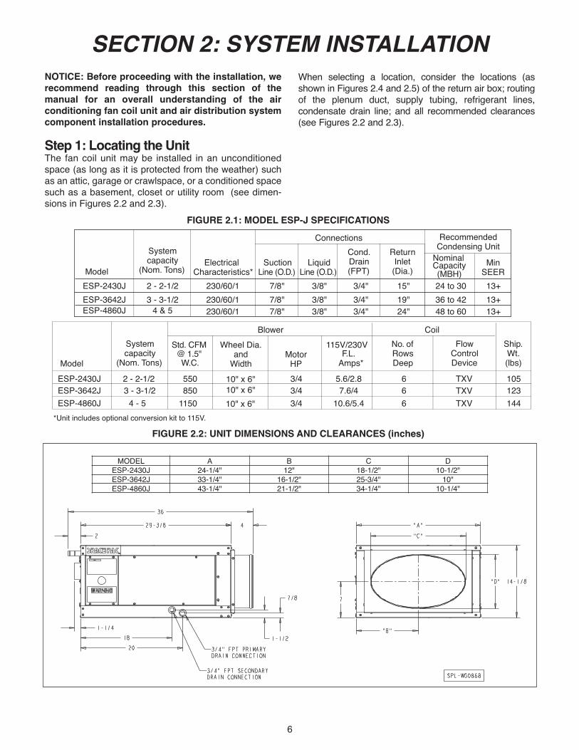
SECTION 2: SYSTEM INSTALLATION NOTICE: Before proceeding with the installation, werecommend reading through this section of themanual for an overall understanding of the airconditioning fan coil unit and air distribution systemcomponent installation procedures.
Step 1: Locating the UnitThe fan coil unit may be installed in an unconditionedspace (as long as it is protected from the weather) suchas an attic, garage or crawlspace, or a conditioned spacesuch as a basement, closet or utility room (see dimen-sions in Figures 2.2 and 2.3).
When selecting a location, consider the locations (asshown in Figures 2.4 and 2.5) of the return air box; routingof the plenum duct, supply tubing, refrigerant lines,condensate drain line; and all recommended clearances(see Figures 2.2 and 2.3).
FIGURE 2.1: MODEL ESP-J SPECIFICATIONS
FIGURE 2.2: UNIT DIMENSIONS AND CLEARANCES (inches)
Model
Systemcapacity
(Nom. Tons)Suction
Line (O.D.)Liquid
Line (O.D.)
Cond.Drain(FPT)
ReturnInlet(Dia.)
Connections RecommendedCondensing Unit
Nominal Capacity(MBH)
MinSEER
ESP-2430JESP-3642JESP-4860J
2 - 2-1/23 - 3-1/2
4 & 5
ElectricalCharacteristics*
230/60/1 230/60/1 230/60/1
7/8"7/8"7/8"
3/8"3/8"3/8"
3/4"3/4"3/4"
15"19"24"
24 to 3036 to 4248 to 60
13+13+13+
Model
Systemcapacity
(Nom. Tons)
Std. CFM @ 1.5" W.C.
MotorHP
F.L.Amps*
No. ofRowsDeep
Blower
Flow
ControlDevice
Ship.Wt.(lbs)
ESP-2430JESP-3642JESP-4860J
2 - 2-1/2 3 - 3-1/2
4 - 5
550 3/43/43/4
5.6/2.87.6/4
10.6/5.4
666
TXVTXVTXV
105123144
8501150
CoilWheel Dia. 115V/230V
andWidth
10" x 6"
10" x 6"10" x 6"
*Unit includes optional conversion kit to 115V.
MODEL A B C DESP-2430J 24-1/4" 12" 18-1/2" 10-1/2"ESP-3642J 33-1/4" 16-1/2" 25-3/4" 10"ESP-4860J 43-1/4" 21-1/2" 34-1/4" 10-1/4"

7
CLAMP BAND
CLAMP BAND
RETURN AIR BOXWITH GRILL & FILTER
SPACEPAK FANCOIL UNIT
FLEXIBLE RETURNDUCT (90 BEND)
48" MIN.
PLATFORM (FIELD ERECTED AS SHOWN IN STEP 4)
SUPPLY AIR OUTLET(ALTERNATE LOCATION)
SUPPLY AIR OUTLET
FIGURE 2.4: TYPICAL UNIT INSTALLATION
14 Ft. MAXIMUM FLEXIBLE RETURN DUCT
FAN COIL UNIT
SUPPORT
RETURN AIR BOX
90°
90°
2 Ft. MAX.
PLATFORM (FIELD ERECTED AS SHOWN IN STEP 4)
SUPPORT
SUPPLY AIR
FIGURE 2.5: hORIZONTAL AIR FLOW UNIT INSTALLATION
FIGURE 2.3: CONNECTION LOCATIONS AND ASSEMBLED PLENUM ADAPTOR DIMENSIONS
MODEL A B C2430J 10-1/8" 4-7/8" 9-1/2"3642J 12" 11-7/8" 14"4860J 17" 17" 19"
A
14-5/16"
D
8
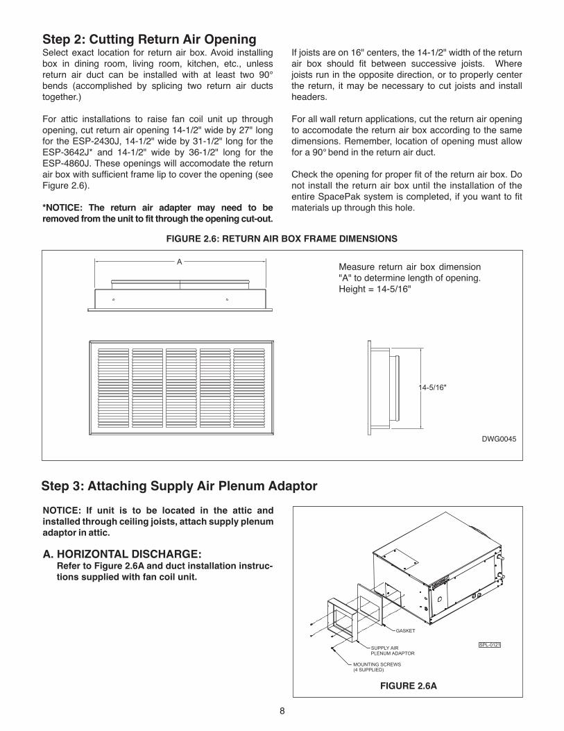
Step 2: Cutting Return Air OpeningIf joists are on 16" centers, the 14-1/2" width of the returnair box should fit between successive joists. Wherejoists run in the opposite direction, or to properly centerthe return, it may be necessary to cut joists and installheaders.
For all wall return applications, cut the return air openingto accomodate the return air box according to the samedimensions. Remember, location of opening must allowfor a 90° bend in the return air duct.
Check the opening for proper fit of the return air box. Donot install the return air box until the installation of the entire SpacePak system is completed, if you want to fitmaterials up through this hole.
FIGURE 2.6: RETURN AIR BOx FRAME DIMENSIONS
Select exact location for return air box. Avoid installingbox in dining room, living room, kitchen, etc., unlessreturn air duct can be installed with at least two 90°bends (accomplished by splicing two return air ductstogether.)
For attic installations to raise fan coil unit up throughopening, cut return air opening 14-1/2" wide by 27" longfor the ESP-2430J, 14-1/2" wide by 31-1/2" long for theESP-3642J* and 14-1/2" wide by 36-1/2" long for theESP-4860J. These openings will accomodate the returnair box with sufficient frame lip to cover the opening (seeFigure 2.6).
*NOTICE: The return air adapter may need to beremoved from the unit to fit through the opening cut-out.
Measure return air box dimension"A" to determine length of opening.Height = 14-5/16"
DWG0045
Step 3: Attaching Supply Air Plenum AdaptorNOTICE: If unit is to be located in the attic andinstalled through ceiling joists, attach supply plenumadaptor in attic.
A. hORIZONTAL DISChARGE: Refer to Figure 2.6A and duct installation instruc-tions supplied with fan coil unit.
GASKET
SUPPLY AIRPLENUM ADAPTOR
MOUNTING SCREWS(4 SUPPLIED)
SPL-0121
FIGURE 2.6A

9
Step 4: Setting the UnitConstruct a platform for the fan coil unit, as shown inFigure 2.8. The platform can be constructed of 2 x 4 x 4(minimum), 2 x 6, 2 x 8 and 2 x 10 lumber, as necessaryto achieve proper pitch of 1/4" per foot for the condensatedrain line. Figure 2.7 shows the approximate normalallowable run of condensate piping as a function of theframing lumber used for platform construction. Theplatform covering should be 1/2" plywood minimum.
Attach vibration isolation pads (supplied inside fan coilunit) to platform covering as shown in Fig. 2.8.
Secure the platform to the joist or floor, depending on location selected for the fan coil unit. Make sure platformis level.
For locations where the fan coil unit will be suspended,suspend platform from overhead by 1/4" threaded rods.
NOTICE: Allow room on sides for servicing.
For installations with a return air box and return air duct,set fan coil unit on the platform with the elliptical openingfacing in the direction of the return air box. DO NOT letthe supply air plenum adaptor support the weight of theunit.
Do not secure the unit to the platform, as the weight of the unit will hold it in position.
Step 5: Connecting Refrigerant LinesConnect refrigerant lines from the outdoor condensing unitto the fan coil unit in accordance with its manufacturer'ssizing recommendations for the length of the piping run.Proper line sizing is critical to the operation of the system.Always use proper brazing procedures. A trickle flow (2PSI)of dry nitrogen to avoid scale or blockage in the pipingsystem is recommended while brazing. SpacePak alsorecommends installing a sight glass on the liquid lineoutside of the unit as an aid for accurately charging thesystem.
30" 25"
4 STRIPS 4" x 30" x 1" THICKPOLYURETHANE FOAM
FOR MODEL ESP-2430J
AIR FLOW1 STRIP 4" x 15" x 1" THICK
POLYURETHANE FOAM
1 STRIP 4" x 9" x 1" THICKPOLYURETHANE FOAM
7 STRIPS 4" x 30" x 1" THICKPOLYURETHANE FOAM
FOR MODEL ESP-4860J
30"44"
AIR FLOW
30" 34"
5 STRIPS 4" x 30" x 1" THICKPOLYURETHANE FOAM
FOR MODEL ESP-3642J
AIR FLOW
1 STRIP 4" x 14" x 1" THICKPOLYURETHANE FOAM
1 STRIP 4" x 15" x 1" THICKPOLYURETHANE FOAM
1 STRIP 4" x 16" x 1" THICKPOLYURETHANE FOAM
1 STRIP 4" x 15" x 1" THICKPOLYURETHANE FOAM
FIGURE 2.8: MOUNTING PLATFORMS ShOWN WITh VIBRATION ISOLATION STRIPS
FIGURE 2.7: CONDENSATE PIPING RUNS
LUMBER SIZE
MAXIMUM HORIZONTAL
2 X 4
8’
2 X 6
16’
2 X 8
24’
2 X 10
32’

10
NOTICE: It is a requirement of the InternationalMechanical Code (307.2.3) to install a secondary drainor an auxiliary drain pan where damage to anybuilding components will occur as a result of overflowfrom the equipment drain pan or stoppage in thecondensate drain piping from a cooling or anevaporator coil. Follow local code requirements.
Refer to Fig. 2.2 for primary and secondary condensatedrain locations. Components for the PVC condensatetrap are provided in a separate bag with fan coil unit (seeFig. 2.9) and should be cemented together with PVCpipe cement.
Do not use substitute trap. Do not cutoff or alter trap components.
Screw male adapter (see Fig. 2.9) into unit’s primarycondensate drain connection. Assemble and cementremaining components together. Then cement assemblyto male adapter. The 45° elbow provides an offset frombeneath unit suction line for access to clean-out plug.
Run a condensate line from the trap to a suitable drainthat’s in accordance with local codes. Make sure the lineis pitched 1/4" per foot.
NOTICE: The secondary drain connection requiresfield supplied components to complete installation.Follow local code requirements.
NOTICE: Never connect condensate line to a closeddrain system.
Step 6: Installing the Condensate Trap & Line
ITEM123456
MALE ADAPTER, 3/4''DESCRIPTION
ELBOW 45????, 3/4''
1/2'' PLUG3/4'' X 1/2'' BUSHINGTEE, 3/4''
P-TRAP, 3/4''
3/4'' P-TRAP ASS'Y KIT
WG0127B
NOTE: PIPE SECTIONS ARE FIELD SUPPLIED.
1
23
5
4
6
SEE NOTE
SECOND 3/4" MALE ADAPTER SUPPLIED FOR OVERFLOW CONNECTION
*
*
FIGURE 2.9: CONDENSATE TRAP ASSEMBLY
Step 7: Wiring the Unit
All electrical and control wiring must be installed inaccordance with the codes listed in Section 1 of this manual. Wiring diagram is provided in Figure 2.10. Aseparate 230/60/1 power supply is recommended for theunit. Use standard 15-amp circuit breaker and 14-gaugewire from power supply to unit.
Connect power supply to Terminals L1 and L2 on the highvoltage terminal block. Connect a ground wire to the equipment ground terminal located next to the high volt-age terminal block.
Turn off electrical power supplybefore servicing. Contact with live electric compo-nents can cause shock or death.
Locate the room thermostat on a wall near the return airbox, between 40" to 48" from the floor. Connect the low-voltage thermostat wiring from the room thermostat to thelow voltage control block in the unit.
Connect low voltage from air handler to condensing unitas shown in figure 2.10.
Set DIP switches according to application. See page 12,SpacePak J Series Control DIP switch settings.
Alternately, the unit may be configured to run on 115V,60 hz power. Refer to kit WG0858 for instructions andmaterial to convert from 230V to 115V shipped withthe unit.
Step 8: Installing Air Distribution ComponentsAll plenum duct and supply tubing runs as well as roomterminator locations must be in accordance with airdistribution system requirements listed in Section 1 of thismanual. Where taping of joints is required, UL181approved tape is required.
Plenum Duct InstallationAll tees, elbows and branch runs must be a minimum of 24"
from the fan coil unit or any other tee, elbow or branch run.Keep all tees and elbows to a minimum to keep systempressure drop on larger layouts to a minimum.
NOTICE: Refer to duct installation instructions sup-plied with fan coil unit or follow manufacturers instruc-tions supplied with other duct system types.

11
FIGURE 2.10: MODEL ESP-J 230V WIRING DIAGRAM*
* For 115V conversion instructions see conversion kit supplied separately with the unit.
12
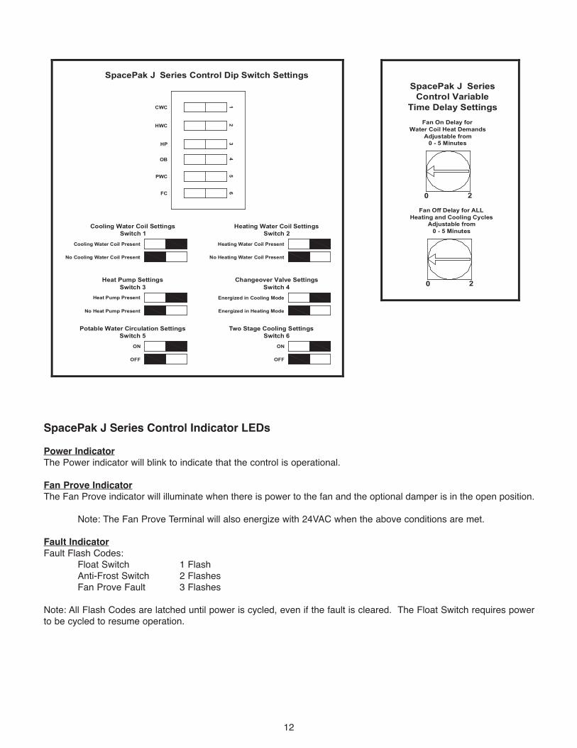
CWC
HWC
HP
OB
PWC
FC
Cooling Water Coil Present
Cooling Water Coil SettingsSwitch 1
No Cooling Water Coil Present
Heat Pump Present
Heat Pump SettingsSwitch 3
No Heat Pump Present
ON
Potable Water Circulation SettingsSwitch 5
OFF
Heating Water Coil Present
Heating Water Coil SettingsSwitch 2
No Heating Water Coil Present
Energized in Cooling Mode
Changeover Valve SettingsSwitch 4
Energized in Heating Mode
ON
Two Stage Cooling SettingsSwitch 6
OFF
SpacePak J Series Control Dip Switch Settings
Fan On Delay forWater Coil Heat Demands
Adjustable from0 - 5 Minutes
SpacePak J SeriesControl Variable
Time Delay Settings
0 2
Fan Off Delay for ALLHeating and Cooling Cycles
Adjustable from0 - 5 Minutes
0 2
12
34
56
SpacePak J Series Control Indicator LEDsPower IndicatorThe Power indicator will blink to indicate that the control is operational.
Fan Prove IndicatorThe Fan Prove indicator will illuminate when there is power to the fan and the optional damper is in the open position.
Note: The Fan Prove Terminal will also energize with 24VAC when the above conditions are met.
Fault IndicatorFault Flash Codes:
Float Switch 1 FlashAnti-Frost Switch 2 FlashesFan Prove Fault 3 Flashes
Note: All Flash Codes are latched until power is cycled, even if the fault is cleared. The Float Switch requires powerto be cycled to resume operation.

13
SOUND ATTENUATING TUBE
THIS RADIUS TOO SHORT
STUD SPACE
TERMINATOR
DRY WALL OR PLASTER
FIGURE 2.11: INCORRECT TUBING INSTALLATION
Room Terminator & Sound Attenuating Tubing InstallationRoom terminators and pre-assembled sound attenuatingtubes are provided in the Installation Kits.
NOTICE: Do not install terminators in a wall in which a sharp bend in the sound attenuating tube is required (seeFigure 2.11). The result would be unacceptable noise.
OPTION: Using a SpacePak Kwik Connect Wall Elbow(Model Number: AC-KCWE) addresses this condition(see Figure 2.12).
In marking location for room terminator (see Figure 2.13),the center of the terminator should be approximately 5"from the wall or, when installed in the corner of a room 5"from both walls.
After marking location, drill a 1/8" diameter hole foroutlet. Verify there is at least 2" for tubing assemblyclearance all around this hole by visual inspection orinserting a bent piece of wire to feel for obstructions.Adjust direction of hole as needed, to gain this 2"clearance. After all clearances have been checked, takea 4" diameter rotary-type hole saw and cut a hole, usingthe 1/8" diameter hole as a pilot.
Assemble spring clips to terminator plate with screwsprovided in installation kit. Tighten clips until they areclose to the thickness of the material they are beingmounted to.
Assemble the room terminator to the sound attenuatingtubing by simply fitting the two pieces together andtwisting until tight (see Figure 2.14). If the terminator is tobe used in a floor location, then field fabricate a smallscreen (1-1/2" square; 1/4 X 1/4 20-gauge galvanizedwire screen) and place screen over opening on the backof the terminator prior to twisting on the kwik-connect (onthe sound attenuating tube).
NOTICE: Do not shorten sound attenuating tubelength. The result would be unacceptable noise.
Push the free end of the sound attenuating tube throughthe 4" hole until the two toggle springs on the room termi-nator snap into place.
Center the two spring clips on a line parallel to thedirection of the tubing routing from the room terminator(see Figure 2.14). This is important since the weight ofthe tubing will have a tendency to cause a part of theterminator to pull away from the ceiling if the clips andtubing do not run parallel.
Then tighten the screws (attached to the terminator) untilthe terminator is snug against the ceiling or floor. Do not overtighten. For installations with floors or ceilingswhich are thicker than normal, longer toggle screws orspecial mounting plates may be required.
TUBING ROUTING
FIGURE 2.14: POSITIONING ROOM TERMINATOR
ININSINSULAINSULATINSULATIINSULATIOINSULATIONINSULATION INSULATION 3/8INSULATION 3/8 INSULATION 3/8 NINSULATION 3/8 NOINSULATION 3/8 NOMINALINSULATION 3/8 NOMINAL
SHEETSHEET SHEET ROCKSHEET ROCK
SOUNDSOUND SOUND ATTENUATORSOUND ATTENUATOR
33.3.5003.500 00.0.6250.625
3/163/16 3/16 GA3/16 GAP3/16 GAP
FOR
3/16 GAP
FOR
3/16 GAP
FOR APP
3/16 GAP
FOR APPL
3/16 GAP
FOR APPLICATIONS
3/16 GAP
FOR APPLICATIONS
3/16 GAP
FOR APPLICATIONS W
3/16 GAP
FOR APPLICATIONS WITH
3/16 GAP
FOR APPLICATIONS WITH
3/16 GAP
FOR APPLICATIONS WITH THICKER
3/16 GAP
FOR APPLICATIONS WITH THICKER
3/16 GAP
FOR APPLICATIONS WITH THICKER WAL
3/16 GAP
FOR APPLICATIONS WITH THICKER WALL
3/16 GAP
FOR APPLICATIONS WITH THICKER WALLBOARD
3/16 GAP
FOR APPLICATIONS WITH THICKER WALLBOARD,
3/16 GAP
FOR APPLICATIONS WITH THICKER WALLBOARD,
3/16 GAP
FOR APPLICATIONS WITH THICKER WALLBOARD, RE
3/16 GAP
FOR APPLICATIONS WITH THICKER WALLBOARD, REM
3/16 GAP
FOR APPLICATIONS WITH THICKER WALLBOARD, REMOVE MATERIAL FROM
3/16 GAP
FOR APPLICATIONS WITH THICKER WALLBOARD, REMOVE MATERIAL FROM
3/16 GAP
FOR APPLICATIONS WITH THICKER WALLBOARD, REMOVE MATERIAL FROM THIS A
3/16 GAP
FOR APPLICATIONS WITH THICKER WALLBOARD, REMOVE MATERIAL FROM THIS AR
3/16 GAP
FOR APPLICATIONS WITH THICKER WALLBOARD, REMOVE MATERIAL FROM THIS AREA TO ALL
3/16 GAP
FOR APPLICATIONS WITH THICKER WALLBOARD, REMOVE MATERIAL FROM THIS AREA TO ALLO
3/16 GAP
FOR APPLICATIONS WITH THICKER WALLBOARD, REMOVE MATERIAL FROM THIS AREA TO ALLOW FOR
3/16 GAP
FOR APPLICATIONS WITH THICKER WALLBOARD, REMOVE MATERIAL FROM THIS AREA TO ALLOW
3/16 GAP
FOR APPLICATIONS WITH THICKER WALLBOARD, REMOVE MATERIAL FROM THIS AREA TO ALLOW FOR PROPER
3/16 GAP
FOR APPLICATIONS WITH THICKER WALLBOARD, REMOVE MATERIAL FROM THIS AREA TO ALLOW FOR PROPER
3/16 GAP
FOR APPLICATIONS WITH THICKER WALLBOARD, REMOVE MATERIAL FROM THIS AREA TO ALLOW FOR PROPER F
3/16 GAP
FOR APPLICATIONS WITH THICKER WALLBOARD, REMOVE MATERIAL FROM THIS AREA TO ALLOW FOR PROPER FI
3/16 GAP
FOR APPLICATIONS WITH THICKER WALLBOARD, REMOVE MATERIAL FROM THIS AREA TO ALLOW FOR PROPER FIT.
3/16 GAP
FOR APPLICATIONS WITH THICKER WALLBOARD, REMOVE MATERIAL FROM THIS AREA TO ALLOW FOR PROPER FIT.
SPL-0050-A
FIGURE 2.12: INSTALLATION WITh KWIK CONNECT WALL ELBOW
4" DIA.
5"
5"
FIGURE 2.13: TERMINATOR MEASUREMENTS
14
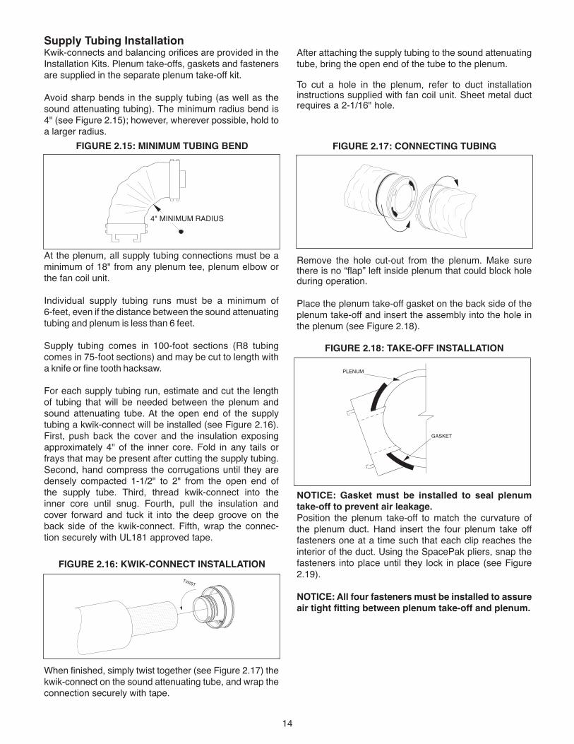
After attaching the supply tubing to the sound attenuatingtube, bring the open end of the tube to the plenum.
To cut a hole in the plenum, refer to duct installationinstructions supplied with fan coil unit. Sheet metal ductrequires a 2-1/16" hole.
Remove the hole cut-out from the plenum. Make surethere is no “flap” left inside plenum that could block holeduring operation.
Place the plenum take-off gasket on the back side of theplenum take-off and insert the assembly into the hole inthe plenum (see Figure 2.18).
NOTICE: Gasket must be installed to seal plenumtake-off to prevent air leakage.Position the plenum take-off to match the curvature of the plenum duct. Hand insert the four plenum take offfasteners one at a time such that each clip reaches theinterior of the duct. Using the SpacePak pliers, snap thefasteners into place until they lock in place (see Figure2.19).
NOTICE: All four fasteners must be installed to assureair tight fitting between plenum take-off and plenum.
Supply Tubing InstallationKwik-connects and balancing orifices are provided in theInstallation Kits. Plenum take-offs, gaskets and fastenersare supplied in the separate plenum take-off kit.
Avoid sharp bends in the supply tubing (as well as thesound attenuating tubing). The minimum radius bend is 4" (see Figure 2.15); however, wherever possible, hold toa larger radius.
At the plenum, all supply tubing connections must be aminimum of 18" from any plenum tee, plenum elbow orthe fan coil unit.
Individual supply tubing runs must be a minimum of 6-feet, even if the distance between the sound attenuatingtubing and plenum is less than 6 feet.
Supply tubing comes in 100-foot sections (R8 tubingcomes in 75-foot sections) and may be cut to length with a knife or fine tooth hacksaw.
For each supply tubing run, estimate and cut the lengthof tubing that will be needed between the plenum andsound attenuating tube. At the open end of the supplytubing a kwik-connect will be installed (see Figure 2.16).First, push back the cover and the insulation exposingapproximately 4" of the inner core. Fold in any tails orfrays that may be present after cutting the supply tubing.Second, hand compress the corrugations until they aredensely compacted 1-1/2" to 2" from the open end ofthe supply tube. Third, thread kwik-connect into theinner core until snug. Fourth, pull the insulation andcover forward and tuck it into the deep groove on theback side of the kwik-connect. Fifth, wrap the connec-tion securely with UL181 approved tape.
When finished, simply twist together (see Figure 2.17) thekwik-connect on the sound attenuating tube, and wrap theconnection securely with tape.
TWIST
FIGURE 2.16: KWIK-CONNECT INSTALLATION
PLENUM
GASKET
FIGURE 2.18: TAKE-OFF INSTALLATION
FIGURE 2.17: CONNECTING TUBING
4" MINIMUM RADIUS
FIGURE 2.15: MINIMUM TUBING BEND

AAAAAAAAAAAAAAAAAAA
AAAAAAAAAAAAAAAROOM TERMINATOR
WINTERSUPPLYSHUT-OFF
RETURN AIRBOX
RETURN AIRFILTER GRILL
15
In accordance with your calculations as to requirementsfor balancing orifices, mount the orifice in the outlet of theplenum take-off (see Figure 2.20), prior to attaching thesupply tubing.
Next, install a kwik-connect in the open end of the supplytubing, using the same procedures as before, and twist together kwik-connects on supply tubing and plenum take-off. Wrap connection securely with tape.
Return Air Box & Duct InstallationRemove the return air grill from the return air box and remove the air filter from the return air grill.
Insert the return box from below for ceiling installation (orfrom the front for wall installations) and fasten with fourscrews through holes provided on the long side of the box.(see Figure 2.21).
FIGURE 2.19: PLENUM TAKE-OFF FASTENER INSTALLATION
FIGURE 2.20: ORIFICE INSTALLATION
FIGURE 2.21: RETURN AIR BOx INSTALLATION
Remove the grill and the filter from the grill frame.Insert the frame into the box and mount in place with thescrews provided through a hole at each corner of theframe. Finally, place the air filter into the frame and replacethe grill. Turn the latches a quarter turn to lock the grill inplace.
Slide a clamp band (provided with return air box) over oneend of the return air duct. Place that end over the ellipticalflange on the fan coil unit (see Figure 2.22). Move theclamp over the flange and tighten so the clamp holds thereturn air duct securely to the flange. Follow the same pro-cedures to attach the return air duct to the return air box(see Figure 2.22).
Winter Supply Shut-Off InstallationSimply insert winter supply shut-offs into the roomterminator openings (see Figure 2.23). Wrap the returnair filter in a plastic bag and reinstall it to block the returnair opening. Winter supply shut-offs prevent moisturefrom collecting in ductwork during winter months. Be sureto remove the plastic bag and all winter supply shut-offsbefore operating the system.
FIGURE 2.23: WINTER SUPPLY ShUT-OFF
FIGURE 2.22: RETURN AIR DUCT INSTALLATION
PLENUM
FASTENER
GASKET
PLENUM TAKE-OFF
GASKET
PLENUM TAKE-OFF
PLENUM
FASTENER
1. HAND INSERT FASTENER INTO PLENUM TAKE-OFF 2. WITH PLIERS, SNAP FASTENER INTO PLACE UNTIL IT LOCKS IN PLACE

16
SEQUENCE OF OPERATIONWhen power is turned on and thermostat fan switch is set to ON and the cooling indicator is set to OFF, the indoor fan motor is energized in approximately 2 minutes.The outdoor unit is off.
When power is turned on and thermostat fan switch is set to ON or AUTO and the cooling indicator to COOL the indoor and outdoor units will start.
AUTO position on the thermostat will stop and start yoursystem when the temperature setting is satisfied. The ONposition on the thermostat will stop the outdoor unit onlywhen the temperature setting is satisfied and the indoorunit will continue to run, recirculating indoor air.
The fan coil unit is equipped with a protective device called an anti-frost control which will automatically stop theoutdoor unit (while the indoor unit continues to run) if iceaccumulates on the indoor unit evaporator coil causingabnormal operating conditions. When the accumulated icehas melted, the anti-frost control will restart the outdoor unit.
The fan coil unit is equipped with primary float switch, and thesystem will automatically shut down if the drain pan is full of water(condensate) and not draining. The system requires service.
PRIOR TO START-UP 1. Check all electrical connections for tightness.
2. Check air filter has been installed in return air box or filter box.
3. Remove all winter supply shut-offs and store them in a safe place.
SYSTEM START-UP & ADJUSTMENTS1. Place thermostat fan switch in ON position and cooling indicator
in OFF position. In about 2 minutes, indoor unit blower will start.
2. Check blower operation for excess noise or vibration.
3. Check entire distribution system for leakage and applyadditional tape where necessary.
4. Set individual fan speedsa. Remove the speed control cover as shown in
Figure 4.1 page 25.b. With the unit powered and operating from a
conventional thermostat, ensure there is no conditioningcall (Thermostat is satisfied) and switch the fan control to “Manual” or “On” to create a G call.
c. With a small screwdriver, turn the potentiometer markedFlo0 to achieve the desired air flow for fan only operation.
SECTION 3: START-UP & OPERATION d. Create a “Cool” call by placing the thermostat in Cooling
mode (if present) and setting the Temperature setpointbelow the current room temperature. Ensure any timedelay has expired and the thermostat has sent a Y1 call.
e. With a small screwdriver, turn the potentiometer marked Flo1 to achieve the desired air flow for normal cooling operation.
f. Create a “Heat” call by placing the thermostat in Heating mode (if present) and setting the Temperaturesetpoint above the current room temperature. Ensure any time delay has expired and the thermostathas sent a W1/OB call.
g. With a small screwdriver, turn the potentiometer marked Flo2 to achieve the desired air flow for normal heating operation.
h. For two stage thermostats only. Review the thermostatmanufacturer’s literature to learn how to create a Second Stage heating or cooling call (usually based upon time to satisfy or temperature difference between room andsetpoint) Create this condition to initiate a Y2 or W2 call.
i. Create a "Second Stage Cooling" call and with a small screwdriver, turn the potentiometer on the speed control marked Flo3, to achieve the desired air flow for "High" Cooling operation.
j. Create a "Second Stage Heating" call and with a small screwdriver, turn the potentiometer on the speed control marked Flo4, to achieve the desired air flow for "High" Heating operation.
k. Replace the speed control cover.
Flo0Fan Only
Flo1Cooling
Flo2Heating
Flo3Stage 2Cooling
Flo4Stage 2Heating
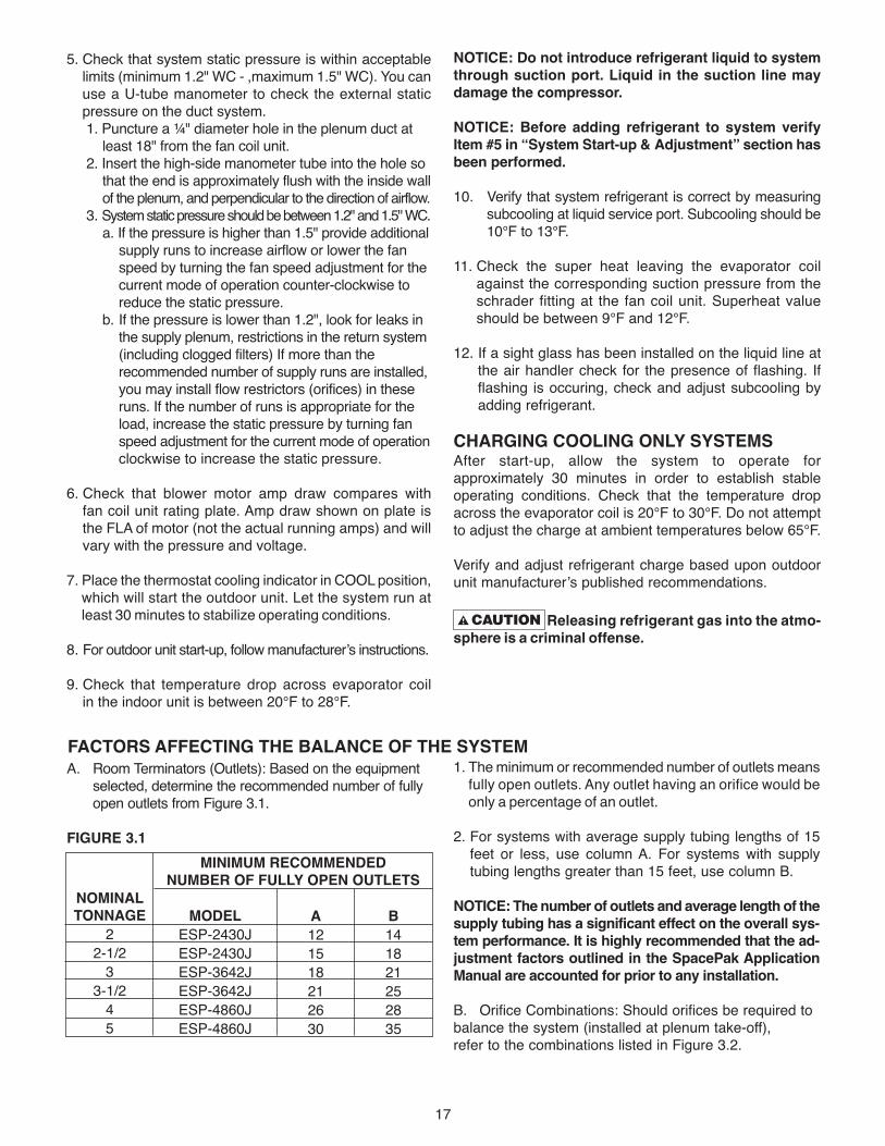
5. Check that system static pressure is within acceptablelimits (minimum 1.2" WC - ,maximum 1.5" WC). You canuse a U-tube manometer to check the external staticpressure on the duct system.1. Puncture a ¼" diameter hole in the plenum duct at
least 18" from the fan coil unit. 2. Insert the high-side manometer tube into the hole so
that the end is approximately flush with the inside wallof the plenum, and perpendicular to the direction of airflow.
3. System static pressure should be between 1.2" and 1.5" WC.a. If the pressure is higher than 1.5" provide additional
supply runs to increase airflow or lower the fan speed by turning the fan speed adjustment for the current mode of operation counter-clockwise to reduce the static pressure.
b. If the pressure is lower than 1.2", look for leaks in the supply plenum, restrictions in the return system(including clogged filters) If more than the recommended number of supply runs are installed,you may install flow restrictors (orifices) in these runs. If the number of runs is appropriate for the load, increase the static pressure by turning fan speed adjustment for the current mode of operationclockwise to increase the static pressure.
6. Check that blower motor amp draw compares with fan coil unit rating plate. Amp draw shown on plate is the FLA of motor (not the actual running amps) and willvary with the pressure and voltage.
7. Place the thermostat cooling indicator in COOL position,which will start the outdoor unit. Let the system run atleast 30 minutes to stabilize operating conditions.
8. For outdoor unit start-up, follow manufacturer’s instructions.
9. Check that temperature drop across evaporator coil in the indoor unit is between 20°F to 28°F.
NOTICE: Do not introduce refrigerant liquid to systemthrough suction port. Liquid in the suction line maydamage the compressor.
NOTICE: Before adding refrigerant to system verifyItem #5 in “System Start-up & Adjustment” section hasbeen performed.
10. Verify that system refrigerant is correct by measuringsubcooling at liquid service port. Subcooling should be10°F to 13°F.
11. Check the super heat leaving the evaporator coilagainst the corresponding suction pressure from theschrader fitting at the fan coil unit. Superheat valueshould be between 9°F and 12°F.
12. If a sight glass has been installed on the liquid line atthe air handler check for the presence of flashing. Ifflashing is occuring, check and adjust subcooling byadding refrigerant.
ChARGING COOLING ONLY SYSTEMSAfter start-up, allow the system to operate forapproximately 30 minutes in order to establish stableoperating conditions. Check that the temperature dropacross the evaporator coil is 20°F to 30°F. Do not attemptto adjust the charge at ambient temperatures below 65°F.
Verify and adjust refrigerant charge based upon outdoorunit manufacturer’s published recommendations.
Releasing refrigerant gas into the atmo-sphere is a criminal offense.
A. Room Terminators (Outlets): Based on the equipment selected, determine the recommended number of fully open outlets from Figure 3.1.
FIGURE 3.1
NOMINAL TONNAGE
22-1/2
33-1/2
45
MODELESP-2430JESP-2430JESP-3642JESP-3642JESP-4860JESP-4860J
A121518212630
MINIMUM RECOMMENDED NUMBER OF FULLY OPEN OUTLETS
B141821252835
FACTORS AFFECTING ThE BALANCE OF ThE SYSTEM1. The minimum or recommended number of outlets means
fully open outlets. Any outlet having an orifice would beonly a percentage of an outlet.
2. For systems with average supply tubing lengths of 15feet or less, use column A. For systems with supplytubing lengths greater than 15 feet, use column B.
NOTICE: The number of outlets and average length of thesupply tubing has a significant effect on the overall sys-tem performance. It is highly recommended that the ad-justment factors outlined in the SpacePak ApplicationManual are accounted for prior to any installation.
B. Orifice Combinations: Should orifices be required to balance the system (installed at plenum take-off), refer to the combinations listed in Figure 3.2.
17

18
The SpacePak system has been designed to provide years oftrouble-free performance in normal installations. Examinationby the homeowner at the beginning of each cooling season,and in mid-season should assure continued, goodperformance. In addition, the system should be examined bya qualified service professional at least once every year.
BEFORE EACh COOLING SEASON1. Check and clean air filter. The air filter is permanent type.
Remove and clean thoroughly with soap solution and water.
Turn off electrical power supply before servicing. Contact with live electric com-ponents can cause shock or death.
2. Check fan coil unit. Turn off unit power disconnectswitch and remove service access panels.
a. Inspect evaporator coil and blower wheel for build-up of dust and dirt. Clean with solvent and/ or wateras necessary.
b. Replace service access panels and turn on unitpower disconnect switch.
3. Check that unit condensate drain is clear and freerunning, and plug is in cleanout.
SECTION 4: MAINTENANCE 4. For outdoor condensing unit, follow manufacturer’s
maintenance instructions.
5. Follow “System Start-Up & Adjustments” procedures in Section 3 of this manual.
IF SYSTEM FAILS TO OPERATE1. Check that thermostat switch is set for proper mode
of operation and is set below room temperature.
2. Check that outdoor unit is operating.a. Confirm that compressor and fan are operating
properly.b. Confirm voltages to outdoor unit.
IF FAN AND COMPRESSOR AT OUTDOORUNIT ARE NOT RUNNING1. Check Fault Indicator. See Flash Codes, page 12. Float
switch fault will stop fan and compressor.
2. Check for tripped circuit breaker or blown fuse at eitherthe main fuse box or at unit disconnect box on or nearthe condensing unit. Replace blown fuse with samesize and type.
3. Review Troubleshooting Guide beginning on page 19 of this manual.
FIGURE 3.2
*For a room with more than two (2) terminals, combinations of theabove may be used to achieve the desired fractional number.
2" SUPPLY TUBING LENGTH ADJUSTMENT FACTOR CHART RUN 6' 8' 10' 12' 15' 20' 25' 30'
FACTOR .85 .88 .90 .94 1.0 1.1 1.25 1.50
DESIRED NUMBEROF TERMINALS*
.5.65.85
1.001.151.301.501.651.701.801.851.952.00
TERMINAL - ORIFICE COMBINATION
(1) .5 (1) .35 (1) .15 (1) (1) .5 + (1) .35 (2) .35 (1) .35 + (1) .15 or (1) + (1) .5 or (3) .5 (1) + (1) .35 or (2) .5 + (1) .35 (2) .15 (2) .35 + (1) .5 (1) + (1) .15 (3) .35 (2)
C. Supply Tubing Length: An outlet with a supply tubing length of 15 feet is considered one, fully opened outlet.For other lengths refer to Figure 3.3 for adjustmentfactors.
FIGURE 3.3
19
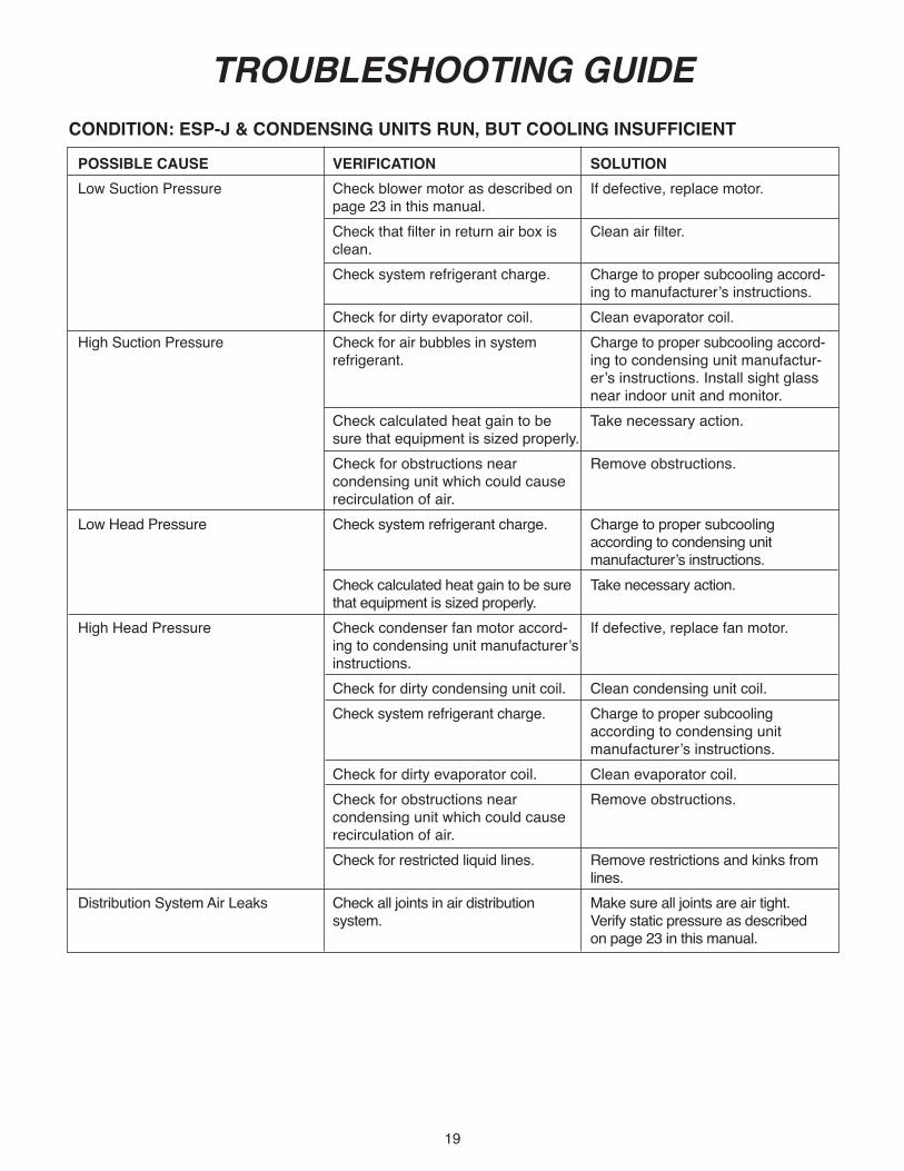
TROUBLESHOOTING GUIDE
POSSIBLE CAUSE VERIFICATION SOLUTIONLow Suction Pressure Check blower motor as described on If defective, replace motor. page 23 in this manual. Check that filter in return air box is Clean air filter. clean. Check system refrigerant charge. Charge to proper subcooling accord- ing to manufacturer’s instructions. Check for dirty evaporator coil. Clean evaporator coil.High Suction Pressure Check for air bubbles in system Charge to proper subcooling accord- refrigerant. ing to condensing unit manufactur- er’s instructions. Install sight glass near indoor unit and monitor. Check calculated heat gain to be Take necessary action. sure that equipment is sized properly. Check for obstructions near Remove obstructions. condensing unit which could cause recirculation of air.Low Head Pressure Check system refrigerant charge. Charge to proper subcooling according to condensing unit manufacturer’s instructions. Check calculated heat gain to be sure Take necessary action. that equipment is sized properly.High Head Pressure Check condenser fan motor accord- If defective, replace fan motor. ing to condensing unit manufacturer’s instructions. Check for dirty condensing unit coil. Clean condensing unit coil. Check system refrigerant charge. Charge to proper subcooling according to condensing unit manufacturer’s instructions. Check for dirty evaporator coil. Clean evaporator coil. Check for obstructions near Remove obstructions. condensing unit which could cause recirculation of air. Check for restricted liquid lines. Remove restrictions and kinks from lines.Distribution System Air Leaks Check all joints in air distribution Make sure all joints are air tight. system. Verify static pressure as described on page 23 in this manual.
CONDITION: ESP-J & CONDENSING UNITS RUN, BUT COOLING INSUFFICIENT
20
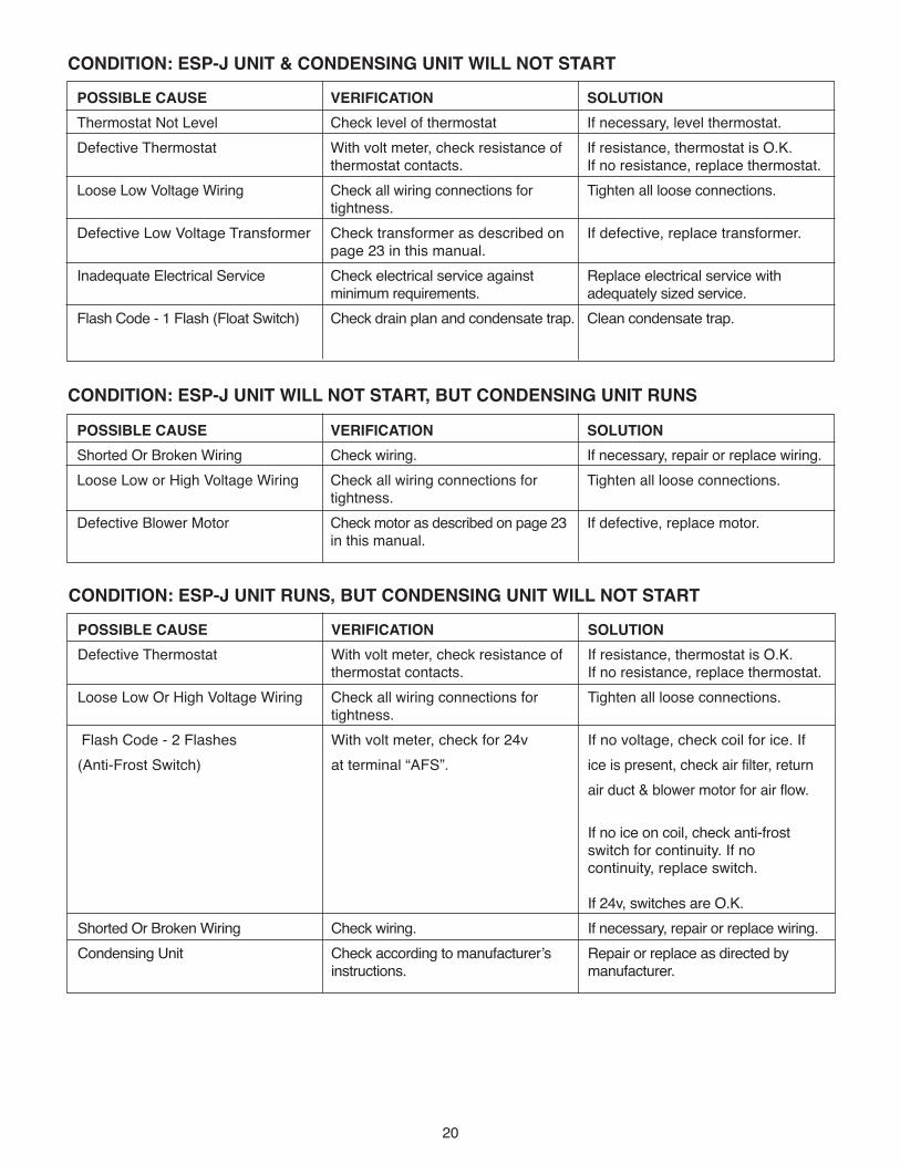
POSSIBLE CAUSE VERIFICATION SOLUTIONThermostat Not Level Check level of thermostat If necessary, level thermostat.Defective Thermostat With volt meter, check resistance of If resistance, thermostat is O.K. thermostat contacts. If no resistance, replace thermostat.Loose Low Voltage Wiring Check all wiring connections for Tighten all loose connections. tightness.Defective Low Voltage Transformer Check transformer as described on If defective, replace transformer. page 23 in this manual.Inadequate Electrical Service Check electrical service against Replace electrical service with minimum requirements. adequately sized service.Flash Code - 1 Flash (Float Switch) Check drain plan and condensate trap. Clean condensate trap.
CONDITION: ESP-J UNIT & CONDENSING UNIT WILL NOT START
POSSIBLE CAUSE VERIFICATION SOLUTIONShorted Or Broken Wiring Check wiring. If necessary, repair or replace wiring.Loose Low or High Voltage Wiring Check all wiring connections for Tighten all loose connections. tightness.Defective Blower Motor Check motor as described on page 23 If defective, replace motor. in this manual.
CONDITION: ESP-J UNIT WILL NOT START, BUT CONDENSING UNIT RUNS
POSSIBLE CAUSE VERIFICATION SOLUTIONDefective Thermostat With volt meter, check resistance of If resistance, thermostat is O.K. thermostat contacts. If no resistance, replace thermostat.Loose Low Or High Voltage Wiring Check all wiring connections for Tighten all loose connections. tightness.Flash Code - 2 Flashes With volt meter, check for 24v If no voltage, check coil for ice. If(Anti-Frost Switch) at terminal “AFS”. ice is present, check air filter, return air duct & blower motor for air flow. If no ice on coil, check anti-frost switch for continuity. If no continuity, replace switch. If 24v, switches are O.K.Shorted Or Broken Wiring Check wiring. If necessary, repair or replace wiring.Condensing Unit Check according to manufacturer’s Repair or replace as directed by instructions. manufacturer.
CONDITION: ESP-J UNIT RUNS, BUT CONDENSING UNIT WILL NOT START
21
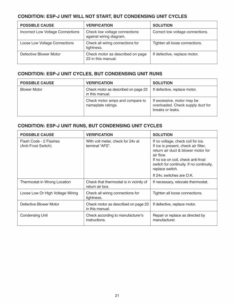
POSSIBLE CAUSE VERIFICATION SOLUTIONIncorrect Low Voltage Connections Check low voltage connections Correct low voltage connections. against wiring diagram. Loose Low Voltage Connections Check all wiring connections for Tighten all loose connections. tightness.Defective Blower Motor Check motor as described on page If defective, replace motor. 23 in this manual.
CONDITION: ESP-J UNIT WILL NOT START, BUT CONDENSING UNIT CYCLES
POSSIBLE CAUSE VERIFICATION SOLUTIONBlower Motor Check motor as described on page 23 If defective, replace motor. in this manual. Check motor amps and compare to If excessive, motor may be nameplate ratings. overloaded. Check supply duct for breaks or leaks.
CONDITION: ESP-J UNIT CYCLES, BUT CONDENSING UNIT RUNS
POSSIBLE CAUSE VERIFICATION SOLUTIONFlash Code - 2 Flashes With volt meter, check for 24v at If no voltage, check coil for ice.(Anti-Frost Switch) terminal “AFS”. If ice is present, check air filter, return air duct & blower motor for air flow. If no ice on coil, check anti-frost switch for continuity. If no continuity, replace switch. If 24v, switches are O.K.Thermostat in Wrong Location Check that thermostat is in vicinity of If necessary, relocate thermostat. return air box. Loose Low Or High Voltage Wiring Check all wiring connections for Tighten all loose connections. tightness. Defective Blower Motor Check motor as described on page 23 If defective, replace motor. in this manual. Condensing Unit Check according to manufacturer’s Repair or replace as directed by instructions. manufacturer.
CONDITION: ESP-J UNIT RUNS, BUT CONDENSING UNIT CYCLES
22
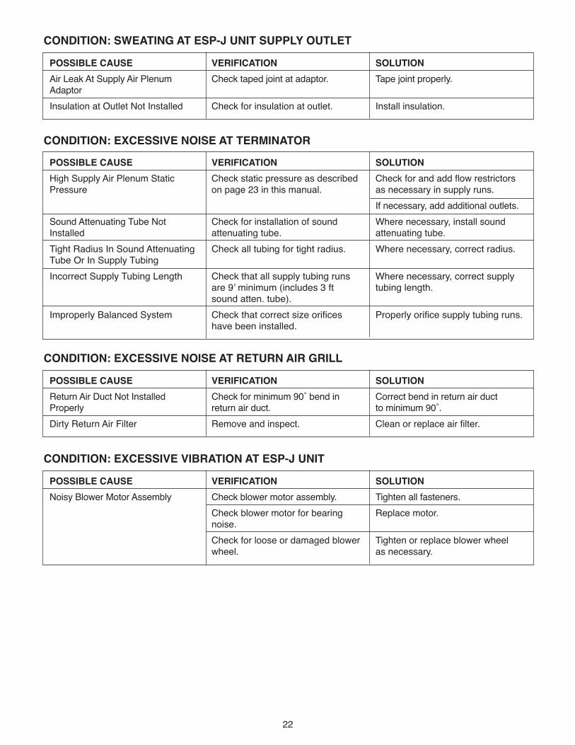
POSSIBLE CAUSE VERIFICATION SOLUTIONHigh Supply Air Plenum Static Check static pressure as described Check for and add flow restrictors Pressure on page 23 in this manual. as necessary in supply runs. If necessary, add additional outlets.Sound Attenuating Tube Not Check for installation of sound Where necessary, install soundInstalled attenuating tube. attenuating tube.Tight Radius In Sound Attenuating Check all tubing for tight radius. Where necessary, correct radius.Tube Or In Supply Tubing Incorrect Supply Tubing Length Check that all supply tubing runs Where necessary, correct supply are 9’ minimum (includes 3 ft tubing length. sound atten. tube).Improperly Balanced System Check that correct size orifices Properly orifice supply tubing runs. have been installed.
CONDITION: EXCESSIVE NOISE AT TERMINATOR
POSSIBLE CAUSE VERIFICATION SOLUTIONAir Leak At Supply Air Plenum Check taped joint at adaptor. Tape joint properly.AdaptorInsulation at Outlet Not Installed Check for insulation at outlet. Install insulation.
CONDITION: SWEATING AT ESP-J UNIT SUPPLY OUTLET
POSSIBLE CAUSE VERIFICATION SOLUTIONNoisy Blower Motor Assembly Check blower motor assembly. Tighten all fasteners. Check blower motor for bearing Replace motor. noise. Check for loose or damaged blower Tighten or replace blower wheel wheel. as necessary.
CONDITION: EXCESSIVE VIBRATION AT ESP-J UNIT
POSSIBLE CAUSE VERIFICATION SOLUTIONReturn Air Duct Not Installed Check for minimum 90˚ bend in Correct bend in return air ductProperly return air duct. to minimum 90˚.Dirty Return Air Filter Remove and inspect. Clean or replace air filter.
CONDITION: EXCESSIVE NOISE AT RETURN AIR GRILL

23
CHECKING ESP-J BLOWER MOTOR1. With voltmeter, check for selected voltage at input ter-
minals, L1 to N for 115V, L1 to L2 for 230V. Measuredvoltage should be ± 10V of selected line voltage.
2. Refer to SYSTEM START-UP AND ADJUSTMENTSsection. Ensure that the operating speed for the cur-rent operating mode is adjusted, and none of thespeed adjustments are set to “zero” (Fully CCW).
3. Once any time delay has expired, the motor should re-spond, by ramping up or down at a perceptible rate,when the speed adjustment screw is moved at least ¼turn.
CHECK ESP-J LOW VOLTAGE TRANSFORMER1. Verify that the unit is configured for the selected line
voltage connected to the input terminal strip, 120V or230V. Refer to STEP: 7 Wiring the Unit.
2. Measure the input voltage, either 120V L1 to N, or230V L1 to L2. Input voltage should be within ±10%of nominal value.
3. If no voltage or voltage outside this range, verifybuilding power supply.
4. If proper voltage is present at the input terminal strip,check transformer secondary voltage for 24V ±10%across the blue and yellow terminals at the 24VACterminal strip.
5. If measured voltage is zero, or outside this range, re-place the transformer.
CHECK EXTERNAL STATIC PRESSUREYou can use a U-tube manometer to check the externalstatic pressure on the duct system.1. Puncture a ¼" diameter hole in the plenum duct at
least 18" from the fan coil unit. 2. Insert the high-side manometer tube into the hole so
that the end is approximately flush with the insidewall of the plenum, and perpendicular to the directionof airflow.
3. System static pressure should be between 1.2" and1.5" WC.a. If the pressure is higher than 1.5" provide addi-
tional supply runs to increase airflow or lower thefan speed by turning the fan speed adjustment forthe current mode of operation counter-clockwiseto reduce the static pressure.
b. If the pressure is lower than 1.2", look for leaks inthe supply plenum, restrictions in the return sys-tem (including clogged filters) If more than the rec-ommended number of supply runs are installed,you may install flow restrictors (orifices) in theseruns. If the number of runs is appropriate for theload, increase the static pressure by turning fanspeed adjustment for the current mode of opera-tion clockwise to increase the static pressure.

24
Customer / Dealer Data:
Name:
Address:
Tel (day) (eve)
Installing Dealer / Contractor:
Name:
Tel:
Equipment Data:
SPACEPAK Model # ESP / WCSP -
SPACEPAK Serial #
SPACEPAK Date of Installation:
Cond Unit Mfr:
Cond Unit Mod #:
Rated Capacity: BTUH; SEER:
Air-side Data:
Total # of outlets: ; Supply tube length: Ft (avg)(Please sketch duct layout on reverse side of this sheet, noting all fittingsand distances, including return duct size / length)
Air Filter: Size (LxHxD)
Type (pleated, etc):
Is the filter clean? (Y/N)
Static Pressure (Ps) in supply plenum: "WG(Measure at approximately 3 ft downstream of blower discharge)
Ps in return duct (downstream of filter, upstream of coil) "WG
SpacePak Motor: Amps (measured): Amps
Voltage (measured): Volts
Air Temperatures:
@ Return (indoor ambient): °FDB; °FWB
@ Condensing unit (outdoor ambient): °F
@ AHU (read 3 ft from fan discharge) °F
@ last supply outlet °F
Refrigeration-side Data:
Line sizes: Liquid Suction
Total equivalent length of lines: Ft; Vertical Rise: Ft.
@ Condensing Unit:
Liquid: psi; Temp: °F; Subcool: °F
Suction: psi; Temp: °F; Superheat: °F
@SpacePak:
Liquid: psi; Temp: °F; Subcool: °F
Suction: psi; Temp: °F; Superheat: °F
Approximate time running before taking readings: Hrs.
Did you adjust the TXV? (Y/N); (If yes, explain):
Refrigerant Charge (if weighed-in): lbs
R410a / R22 (circle one)
Installed options: (circle one)
sight glass filter/drier zone controls
Other:
Water Data: (where applicable)Line sizes: "; Length: FT
Water temperatures:
Suppy: °F; Return °F
Glycol?: (Y/N); % Solution:
NOTES:
Service / Troubleshooting FORM “1A”
REF. PART UNIT PART NO. DESCRIPTION SIZE NUMBER
25
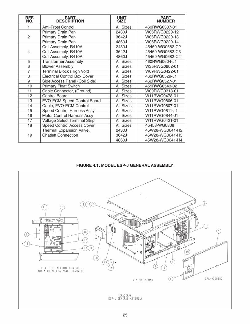
FIGURE 4.1: MODEL ESP-J GENERAL ASSEMBLY
1 Anti-Frost Control All Sizes 460RWG0387-01Primary Drain Pan 2430J W06RWG0220-12
2 Primary Drain Pan 3642J W06RWG0220-13Primary Drain Pan 4860J W06RWG0220-14Coil Assembly, R410A 2430J 45469-WG0682-C2
4 Coil Assembly, R410A 3642J 45469-WG0682-C3Coil Assembly, R410A 4860J 45469-WG0682-C4
5 Transformer Assembly All Sizes 460RWG0604-J16 Blower Assembly All Sizes W35RWG0802-017 Terminal Block (High Volt) All Sizes W09RWG0422-018 Electrical Control Box Cover All Sizes 462RWG0529-J19 Side Access Panel (Coil Side) All Sizes 462RWG0527-0110 Primary Float Switch All Sizes 455RWG0543-0211 Cable Connector, (Ground) All Sizes W09RWG0313-0112 Control Board All Sizes W11RWG0478-0113 EVO-ECM Speed Control Board All Sizes W11RWG0806-0114 Cable, EVO-ECM Control All Sizes W11RWG0807-0115 Speed Control Harness Assy All Sizes W11RWG0811-J116 Motor Control Harness Assy All Sizes W11RWG0844-J117 Voltage Select Terminal Strip All Sizes W11RWG0421-0118 Speed Control Access Cover All Sizes 45458-WG0808
Thermal Expansion Valve, 2430J 45W28-WG0641-H219 Chatleff Connection 3642J 45W28-WG0641-H3
4860J 45W28-WG0641-H4

LIMITED WARRANTYCentral Air Conditioning Products
The “Manufacturer” warrants to the original owner at the original installation site that the Central AirConditioning Products (the “Product”) will be free from defects in material or workmanship for a period not toexceed one (1) year from the startup or eighteen (18) months from date of shipment from the factory, whicheveroccurs first. If upon examination by the Manufacturer the Product is shown to have a defect in material orworkmanship during the warranty period, the Manufacturer will repair or replace, at its option, that part of theProduct which is shown to be defective.
This limited warranty does not apply:a) if the Product has been subjected to misuse or neglect, has been accidentally or intentionally
damaged, has not been installed, maintained or operated in accordance with the furnished writteninstructions, or has been altered or modified in any way.
b) to any expenses, including labor or material, incurred during removal or reinstallation of the defectiveProduct or parts thereof.
c) to any workmanship of the installer of the Product.
This limited warranty is conditional upon:a) shipment, to the Manufacturer, of that part of the Product thought to be defective. Goods can only be
returned with prior written approval from the Manufacturer. All returns must be freight prepaid.b) determination, in the reasonable opinion of the Manufacturer, that there exists a defect in material or
workmanship.
Repair or replacement of any part under this Limited Warranty shall not extend the duration of the warranty withrespect to such repaired or replaced part beyond the stated warranty period.
ThIS LIMITED WARRANTY IS IN LIEU OF ALL OThER WARRANTIES, EIThER ExPRESS OR IMPLIED,AND ALL SUCh OThER WARRANTIES, INCLUDING WIThOUT LIMITATION IMPLIED WARRANTIES OFMERChANTABILITY OR FITNESS FOR A PARTICULAR PURPOSE, ARE hEREBY DISCLAIMED ANDExCLUDED FROM ThIS LIMITED WARRANTY. IN NO EVENT ShALL ThE MANUFACTURER BE LIABLEIN ANY WAY FOR ANY CONSEQUENTIAL, SPECIAL, OR INCIDENTAL DAMAGES OF ANY NATUREWhATSOEVER, OR FOR ANY AMOUNTS IN ExCESS OF ThE SELLING PRICE OF ThE PRODUCT ORANY PARTS ThEREOF FOUND TO BE DEFECTIVE. ThIS LIMITED WARRANTY GIVES ThE ORIGINALOWNER OF ThE PRODUCT SPECIFIC LEGAL RIGhTS. YOU MAY ALSO hAVE OThER RIGhTS WhIChMAY VARY BY EACh JURISDICTION.

27

IN UNITED STATES: 260 NORTH ELM ST. WESTFIELD, MA 01085 (413) 564-5530/FAX (413) 564-5815IN CANADA: 7555 TRANMERE DRIVE, MISSISSAUGA, ONTARIO, L5S 1L4 (905) 670-5888/FAX (905) 670-5782